

Page 1
Accessories
PROFINET®
Servo Drives 9400
_ _ _ _ _ _ _ _ _ _ _ _ _ _ _ _ _ _ _ _ _ _ _ _ _ _
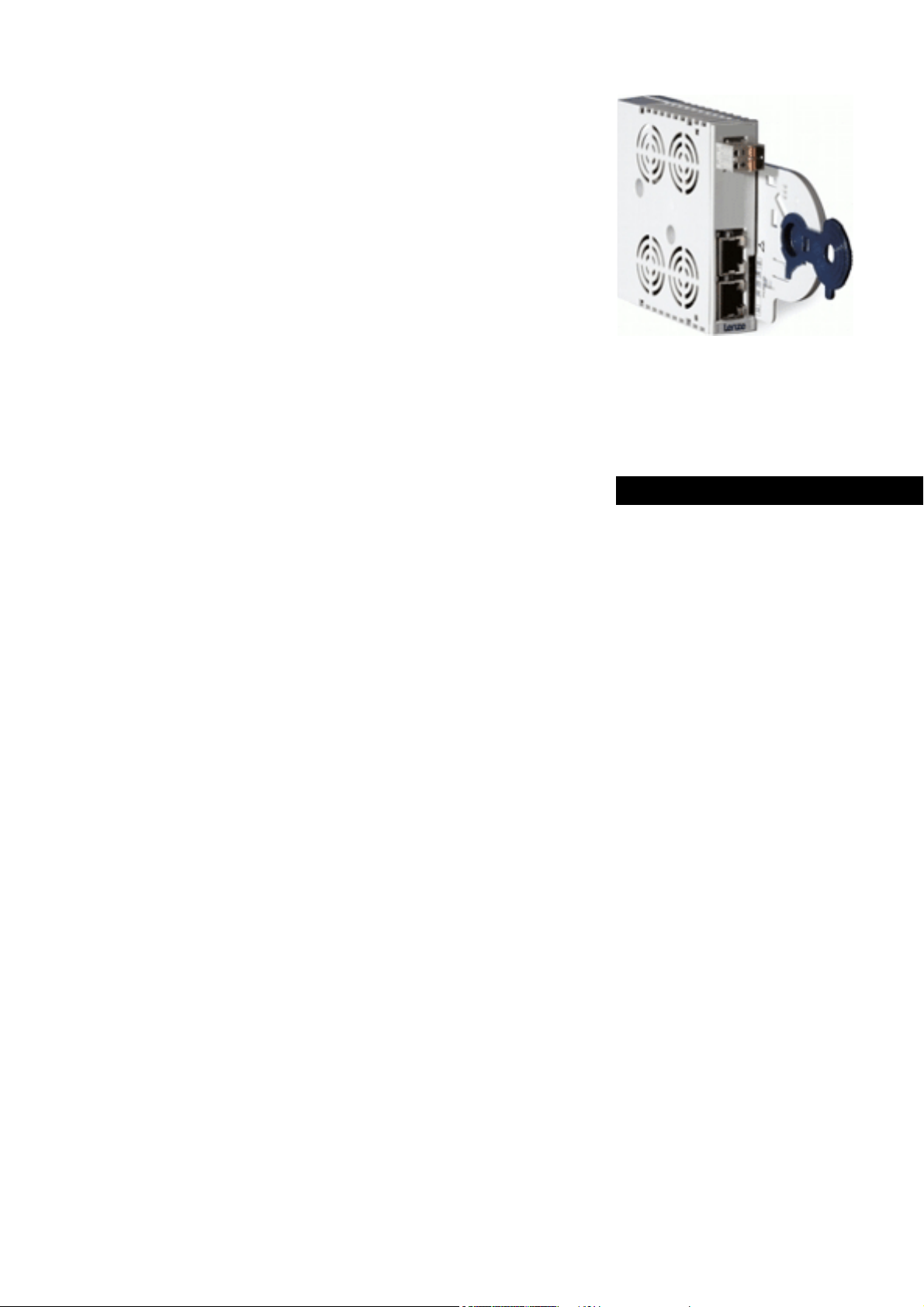
E94AYCER
Communication Manual EN
Ä.N,#ä
13451102
L
Page 2

Contents
_ _ _ _ _ _ _ _ _ _ _ _ _ _ _ _ _ _ _ _ _ _ _ _ _ _ _ _ _ _ _ _ _ _ _ _ _ _ _ _ _ _ _ _ _ _ _ _ _ _ _ _ _ _ _ _ _ _ _ _ _ _ _ _
1 About this documentation _ _ _ _ _ _ _ _ _ _ _ _ _ _ _ _ _ _ _ _ _ _ _ _ _ _ _ _ _ _ _ _ _ _ _ _ _ _ _ 4
1.1 Document history _ _ _ _ _ _ _ _ _ _ _ _ _ _ _ _ _ _ _ _ _ _ _ _ _ _ _ _ _ _ _ _ _ _ _ _ _ _ _ _ _ _ _ _ 6
1.2 Conventions used _ _ _ _ _ _ _ _ _ _ _ _ _ _ _ _ _ _ _ _ _ _ _ _ _ _ _ _ _ _ _ _ _ _ _ _ _ _ _ _ _ _ _ _ 7
1.3 Terminology used _ _ _ _ _ _ _ _ _ _ _ _ _ _ _ _ _ _ _ _ _ _ _ _ _ _ _ _ _ _ _ _ _ _ _ _ _ _ _ _ _ _ _ _ 8
1.4 Notes used _ _ _ _ _ _ _ _ _ _ _ _ _ _ _ _ _ _ _ _ _ _ _ _ _ _ _ _ _ _ _ _ _ _ _ _ _ _ _ _ _ _ _ _ _ _ _ _ 9
2Safety instructions _ _ _ _ _ _ _ _ _ _ _ _ _ _ _ _ _ _ _ _ _ _ _ _ _ _ _ _ _ _ _ _ _ _ _ _ _ _ _ _ _ _ _ _ 10
2.1 General safety and application notes _ _ _ _ _ _ _ _ _ _ _ _ _ _ _ _ _ _ _ _ _ _ _ _ _ _ _ _ _ _ _ _ _ 10
2.2 Device and application-specific safety instructions _ _ _ _ _ _ _ _ _ _ _ _ _ _ _ _ _ _ _ _ _ _ _ _ _ _ 11
2.3 Residual hazards _ _ _ _ _ _ _ _ _ _ _ _ _ _ _ _ _ _ _ _ _ _ _ _ _ _ _ _ _ _ _ _ _ _ _ _ _ _ _ _ _ _ _ _ _ 11
3 Product description _ _ _ _ _ _ _ _ _ _ _ _ _ _ _ _ _ _ _ _ _ _ _ _ _ _ _ _ _ _ _ _ _ _ _ _ _ _ _ _ _ _ _ 12
3.1 Application as directed _ _ _ _ _ _ _ _ _ _ _ _ _ _ _ _ _ _ _ _ _ _ _ _ _ _ _ _ _ _ _ _ _ _ _ _ _ _ _ _ _ 12
3.2 Identification _ _ _ _ _ _ _ _ _ _ _ _ _ _ _ _ _ _ _ _ _ _ _ _ _ _ _ _ _ _ _ _ _ _ _ _ _ _ _ _ _ _ _ _ _ _ _ 12
3.3 Product features _ _ _ _ _ _ _ _ _ _ _ _ _ _ _ _ _ _ _ _ _ _ _ _ _ _ _ _ _ _ _ _ _ _ _ _ _ _ _ _ _ _ _ _ _ 13
3.4 Terminals and interfaces _ _ _ _ _ _ _ _ _ _ _ _ _ _ _ _ _ _ _ _ _ _ _ _ _ _ _ _ _ _ _ _ _ _ _ _ _ _ _ _ 14
4 Technical data _ _ _ _ _ _ _ _ _ _ _ _ _ _ _ _ _ _ _ _ _ _ _ _ _ _ _ _ _ _ _ _ _ _ _ _ _ _ _ _ _ _ _ _ _ _ 15
4.1 General data and operating conditions _ _ _ _ _ _ _ _ _ _ _ _ _ _ _ _ _ _ _ _ _ _ _ _ _ _ _ _ _ _ _ _ 15
4.2 Protocol data _ _ _ _ _ _ _ _ _ _ _ _ _ _ _ _ _ _ _ _ _ _ _ _ _ _ _ _ _ _ _ _ _ _ _ _ _ _ _ _ _ _ _ _ _ _ _ 16
4.3 Communication time _ _ _ _ _ _ _ _ _ _ _ _ _ _ _ _ _ _ _ _ _ _ _ _ _ _ _ _ _ _ _ _ _ _ _ _ _ _ _ _ _ _ 16
4.4 Internal switch latency _ _ _ _ _ _ _ _ _ _ _ _ _ _ _ _ _ _ _ _ _ _ _ _ _ _ _ _ _ _ _ _ _ _ _ _ _ _ _ _ _ 17
4.5 Protective insulation _ _ _ _ _ _ _ _ _ _ _ _ _ _ _ _ _ _ _ _ _ _ _ _ _ _ _ _ _ _ _ _ _ _ _ _ _ _ _ _ _ _ 18
4.6 Dimensions _ _ _ _ _ _ _ _ _ _ _ _ _ _ _ _ _ _ _ _ _ _ _ _ _ _ _ _ _ _ _ _ _ _ _ _ _ _ _ _ _ _ _ _ _ _ _ 21
5Installation _ _ _ _ _ _ _ _ _ _ _ _ _ _ _ _ _ _ _ _ _ _ _ _ _ _ _ _ _ _ _ _ _ _ _ _ _ _ _ _ _ _ _ _ _ _ _ _ 22
5.1 Mechanical installation _ _ _ _ _ _ _ _ _ _ _ _ _ _ _ _ _ _ _ _ _ _ _ _ _ _ _ _ _ _ _ _ _ _ _ _ _ _ _ _ _ 23
5.1.1 Assembly _ _ _ _ _ _ _ _ _ _ _ _ _ _ _ _ _ _ _ _ _ _ _ _ _ _ _ _ _ _ _ _ _ _ _ _ _ _ _ _ _ _ _ _ 23
5.1.2 Disassembly _ _ _ _ _ _ _ _ _ _ _ _ _ _ _ _ _ _ _ _ _ _ _ _ _ _ _ _ _ _ _ _ _ _ _ _ _ _ _ _ _ _ 23
5.2 Electrical installation _ _ _ _ _ _ _ _ _ _ _ _ _ _ _ _ _ _ _ _ _ _ _ _ _ _ _ _ _ _ _ _ _ _ _ _ _ _ _ _ _ _ 24
5.2.1 Wiring according to EMC guidelines _ _ _ _ _ _ _ _ _ _ _ _ _ _ _ _ _ _ _ _ _ _ _ _ _ _ _ _ _ 24
5.2.2 Network topology _ _ _ _ _ _ _ _ _ _ _ _ _ _ _ _ _ _ _ _ _ _ _ _ _ _ _ _ _ _ _ _ _ _ _ _ _ _ _ 25
5.2.3 PROFINET connection _ _ _ _ _ _ _ _ _ _ _ _ _ _ _ _ _ _ _ _ _ _ _ _ _ _ _ _ _ _ _ _ _ _ _ _ _ 27
5.2.4 Ethernet cable specification _ _ _ _ _ _ _ _ _ _ _ _ _ _ _ _ _ _ _ _ _ _ _ _ _ _ _ _ _ _ _ _ _ _ 29
5.2.5 External voltage supply _ _ _ _ _ _ _ _ _ _ _ _ _ _ _ _ _ _ _ _ _ _ _ _ _ _ _ _ _ _ _ _ _ _ _ _ 31
6 Commissioning _ _ _ _ _ _ _ _ _ _ _ _ _ _ _ _ _ _ _ _ _ _ _ _ _ _ _ _ _ _ _ _ _ _ _ _ _ _ _ _ _ _ _ _ _ 32
6.1 Before initial switch-on _ _ _ _ _ _ _ _ _ _ _ _ _ _ _ _ _ _ _ _ _ _ _ _ _ _ _ _ _ _ _ _ _ _ _ _ _ _ _ _ _ 32
6.2 Configuring the PROFINET IO controller _ _ _ _ _ _ _ _ _ _ _ _ _ _ _ _ _ _ _ _ _ _ _ _ _ _ _ _ _ _ _ _ 33
6.3 Setting the station name _ _ _ _ _ _ _ _ _ _ _ _ _ _ _ _ _ _ _ _ _ _ _ _ _ _ _ _ _ _ _ _ _ _ _ _ _ _ _ _ 35
6.4 Setting the IP configuration _ _ _ _ _ _ _ _ _ _ _ _ _ _ _ _ _ _ _ _ _ _ _ _ _ _ _ _ _ _ _ _ _ _ _ _ _ _ _ 37
6.4.1 Setting via the PROFINET configurator of the »Engineer« _ _ _ _ _ _ _ _ _ _ _ _ _ _ _ _ _ _ 38
6.4.2 Setting via codes in the »Engineer« _ _ _ _ _ _ _ _ _ _ _ _ _ _ _ _ _ _ _ _ _ _ _ _ _ _ _ _ _ _ 40
6.4.3 Setting via Siemens »STEP7« (»HW Konfig«) _ _ _ _ _ _ _ _ _ _ _ _ _ _ _ _ _ _ _ _ _ _ _ _ _ 43
6.4.4 Setting via the Siemens »Primary Setup Tool« _ _ _ _ _ _ _ _ _ _ _ _ _ _ _ _ _ _ _ _ _ _ _ _ 47
6.5 Establishing an online connection via PROFINET with the Lenze »Engineer« _ _ _ _ _ _ _ _ _ _ _ _ 49
6.6 Initial switch-on _ _ _ _ _ _ _ _ _ _ _ _ _ _ _ _ _ _ _ _ _ _ _ _ _ _ _ _ _ _ _ _ _ _ _ _ _ _ _ _ _ _ _ _ _ 51
2 Lenze · E94AYCER communication module (PROFINET®) · Communication Manual · DMS 9.0 EN · 12/2013 · TD17
Page 3

Contents
_ _ _ _ _ _ _ _ _ _ _ _ _ _ _ _ _ _ _ _ _ _ _ _ _ _ _ _ _ _ _ _ _ _ _ _ _ _ _ _ _ _ _ _ _ _ _ _ _ _ _ _ _ _ _ _ _ _ _ _ _ _ _ _
7 Data transfer _ _ _ _ _ _ _ _ _ _ _ _ _ _ _ _ _ _ _ _ _ _ _ _ _ _ _ _ _ _ _ _ _ _ _ _ _ _ _ _ _ _ _ _ _ _ _ 52
8 Process data transfer _ _ _ _ _ _ _ _ _ _ _ _ _ _ _ _ _ _ _ _ _ _ _ _ _ _ _ _ _ _ _ _ _ _ _ _ _ _ _ _ _ _ 53
9 Parameter data transfer _ _ _ _ _ _ _ _ _ _ _ _ _ _ _ _ _ _ _ _ _ _ _ _ _ _ _ _ _ _ _ _ _ _ _ _ _ _ _ _ _ 56
9.1 The acyclic channel (PROFIdrive profile) _ _ _ _ _ _ _ _ _ _ _ _ _ _ _ _ _ _ _ _ _ _ _ _ _ _ _ _ _ _ _ _ 56
9.1.1 Connection establishment of an IO Controller to an IO device _ _ _ _ _ _ _ _ _ _ _ _ _ _ _ 56
9.1.2 Acyclic data transmission process _ _ _ _ _ _ _ _ _ _ _ _ _ _ _ _ _ _ _ _ _ _ _ _ _ _ _ _ _ _ _ 57
9.1.3 Structure of the PROFINET data telegram _ _ _ _ _ _ _ _ _ _ _ _ _ _ _ _ _ _ _ _ _ _ _ _ _ _ 58
9.2 Reading parameters from the drive _ _ _ _ _ _ _ _ _ _ _ _ _ _ _ _ _ _ _ _ _ _ _ _ _ _ _ _ _ _ _ _ _ _ 59
9.2.1 Response to a correctly executed read request _ _ _ _ _ _ _ _ _ _ _ _ _ _ _ _ _ _ _ _ _ _ _ _ 60
9.2.2 Response to a read error _ _ _ _ _ _ _ _ _ _ _ _ _ _ _ _ _ _ _ _ _ _ _ _ _ _ _ _ _ _ _ _ _ _ _ _ 62
9.2.3 Telegram example: Read request _ _ _ _ _ _ _ _ _ _ _ _ _ _ _ _ _ _ _ _ _ _ _ _ _ _ _ _ _ _ _ 63
9.3 Writing parameters to the drive _ _ _ _ _ _ _ _ _ _ _ _ _ _ _ _ _ _ _ _ _ _ _ _ _ _ _ _ _ _ _ _ _ _ _ _ 65
9.3.1 Response to a correctly executed write request _ _ _ _ _ _ _ _ _ _ _ _ _ _ _ _ _ _ _ _ _ _ _ 67
9.3.2 Response to a write error _ _ _ _ _ _ _ _ _ _ _ _ _ _ _ _ _ _ _ _ _ _ _ _ _ _ _ _ _ _ _ _ _ _ _ 67
9.3.3 Telegram example: Write request _ _ _ _ _ _ _ _ _ _ _ _ _ _ _ _ _ _ _ _ _ _ _ _ _ _ _ _ _ _ 69
9.4 Error information (error) _ _ _ _ _ _ _ _ _ _ _ _ _ _ _ _ _ _ _ _ _ _ _ _ _ _ _ _ _ _ _ _ _ _ _ _ _ _ _ _ 71
9.5 Consistent parameter data _ _ _ _ _ _ _ _ _ _ _ _ _ _ _ _ _ _ _ _ _ _ _ _ _ _ _ _ _ _ _ _ _ _ _ _ _ _ _ 73
10 PROFIsafe _ _ _ _ _ _ _ _ _ _ _ _ _ _ _ _ _ _ _ _ _ _ _ _ _ _ _ _ _ _ _ _ _ _ _ _ _ _ _ _ _ _ _ _ _ _ _ _ 74
11 Monitoring _ _ _ _ _ _ _ _ _ _ _ _ _ _ _ _ _ _ _ _ _ _ _ _ _ _ _ _ _ _ _ _ _ _ _ _ _ _ _ _ _ _ _ _ _ _ _ _ 75
11.1 Interruption of PROFINET communication _ _ _ _ _ _ _ _ _ _ _ _ _ _ _ _ _ _ _ _ _ _ _ _ _ _ _ _ _ _ _ 75
11.2 Interruption of internal communication _ _ _ _ _ _ _ _ _ _ _ _ _ _ _ _ _ _ _ _ _ _ _ _ _ _ _ _ _ _ _ _ 76
12 Diagnostics _ _ _ _ _ _ _ _ _ _ _ _ _ _ _ _ _ _ _ _ _ _ _ _ _ _ _ _ _ _ _ _ _ _ _ _ _ _ _ _ _ _ _ _ _ _ _ _ 77
12.1 LED status displays _ _ _ _ _ _ _ _ _ _ _ _ _ _ _ _ _ _ _ _ _ _ _ _ _ _ _ _ _ _ _ _ _ _ _ _ _ _ _ _ _ _ _ 77
12.1.1 Module status displays _ _ _ _ _ _ _ _ _ _ _ _ _ _ _ _ _ _ _ _ _ _ _ _ _ _ _ _ _ _ _ _ _ _ _ _ 78
12.1.2 Fieldbus status displays _ _ _ _ _ _ _ _ _ _ _ _ _ _ _ _ _ _ _ _ _ _ _ _ _ _ _ _ _ _ _ _ _ _ _ _ 79
12.1.3 Status displays at X241 and X242 _ _ _ _ _ _ _ _ _ _ _ _ _ _ _ _ _ _ _ _ _ _ _ _ _ _ _ _ _ _ _ 80
12.2 Diagnosing with the »Engineer« _ _ _ _ _ _ _ _ _ _ _ _ _ _ _ _ _ _ _ _ _ _ _ _ _ _ _ _ _ _ _ _ _ _ _ _ 81
12.3 Diagnostic data _ _ _ _ _ _ _ _ _ _ _ _ _ _ _ _ _ _ _ _ _ _ _ _ _ _ _ _ _ _ _ _ _ _ _ _ _ _ _ _ _ _ _ _ _ 82
13 Error messages _ _ _ _ _ _ _ _ _ _ _ _ _ _ _ _ _ _ _ _ _ _ _ _ _ _ _ _ _ _ _ _ _ _ _ _ _ _ _ _ _ _ _ _ _ _ 83
13.1 Short overview of the PROFINET error messages _ _ _ _ _ _ _ _ _ _ _ _ _ _ _ _ _ _ _ _ _ _ _ _ _ _ _ 83
13.2 Possible causes and remedies _ _ _ _ _ _ _ _ _ _ _ _ _ _ _ _ _ _ _ _ _ _ _ _ _ _ _ _ _ _ _ _ _ _ _ _ _ _ 84
14 Parameter reference _ _ _ _ _ _ _ _ _ _ _ _ _ _ _ _ _ _ _ _ _ _ _ _ _ _ _ _ _ _ _ _ _ _ _ _ _ _ _ _ _ _ _ 89
14.1 Parameters of the standard device that are relevant to communication _ _ _ _ _ _ _ _ _ _ _ _ _ _ 89
14.2 Parameters of the communication module for slot MXI1 _ _ _ _ _ _ _ _ _ _ _ _ _ _ _ _ _ _ _ _ _ _ _ 91
14.3 Parameters of the communication module for slot MXI2 _ _ _ _ _ _ _ _ _ _ _ _ _ _ _ _ _ _ _ _ _ _ _ 101
14.4 Table of attributes _ _ _ _ _ _ _ _ _ _ _ _ _ _ _ _ _ _ _ _ _ _ _ _ _ _ _ _ _ _ _ _ _ _ _ _ _ _ _ _ _ _ _ _ 111
Index _ _ _ _ _ _ _ _ _ _ _ _ _ _ _ _ _ _ _ _ _ _ _ _ _ _ _ _ _ _ _ _ _ _ _ _ _ _ _ _ _ _ _ _ _ _ _ _ _ _ _ 114
Your opinion is important to us _ _ _ _ _ _ _ _ _ _ _ _ _ _ _ _ _ _ _ _ _ _ _ _ _ _ _ _ _ _ _ _ _ _ _ _ _ 118
Lenze · E94AYCER communication module (PROFINET®) · Communication Manual · DMS 9.0 EN · 12/2013 · TD17 3
Page 4

1 About this documentation
_ _ _ _ _ _ _ _ _ _ _ _ _ _ _ _ _ _ _ _ _ _ _ _ _ _ _ _ _ _ _ _ _ _ _ _ _ _ _ _ _ _ _ _ _ _ _ _ _ _ _ _ _ _ _ _ _ _ _ _ _ _ _ _
1 About this documentation
Contents
This documentation exclusively describes the E94AYCER communication module (PROFINET).
Note!
This documentation supplements the mounting instructions supplied with the
controller and the "Servo Drives 9400" hardware manual.
The mounting instructions contain safety instructions that must be observed!
The features and functions of the communication module are described in detail.
Examples illustrate typical applications.
The theoretical context is only explained as far as it is required for understanding the function of
the communication module.
This documentation does not describe any software provided by other manufacturers. No warranty
can be given for corresponding data provided in this documentation. For information on how to use
the software, please refer to the host (PLC, IO Controller) documents.
All brand names mentioned in this documentation are trademarks of their corresponding owners.
Tip!
Detailed information about PROFINET can be found on the homepage of the PROFIBUS user
organisation which also develops the PROFINET communication technology:
www.profibus.com
4 Lenze · E94AYCER communication module (PROFINET®) · Communication Manual · DMS 9.0 EN · 12/2013 · TD17
Page 5

1 About this documentation
_ _ _ _ _ _ _ _ _ _ _ _ _ _ _ _ _ _ _ _ _ _ _ _ _ _ _ _ _ _ _ _ _ _ _ _ _ _ _ _ _ _ _ _ _ _ _ _ _ _ _ _ _ _ _ _ _ _ _ _ _ _ _ _
Target group
This documentation addresses to persons who configure, install, commission, and maintain the
networking and remote maintenance of a machine.
Tip!
Current documentation and software updates with regard to Lenze products can be found
in the download area at:
www.lenze.com
Information regarding the validity
The information given in this documentation is valid for the following devices:
Extension module Type designation From hardware
Communication module PROFINET E94AYCER VE 01.40
Screenshots/application examples
All screenshots in this documentation are application examples. Depending on the firmware
version of the communication module and software version of the installed engineering tools
»Engineer«, »STEP7«)
representation.
, the screenshots in this documentation my differ from the screen
version
From software
version
(e.g.
Lenze · E94AYCER communication module (PROFINET®) · Communication Manual · DMS 9.0 EN · 12/2013 · TD17 5
Page 6
1 About this documentation
1.1 Document history
_ _ _ _ _ _ _ _ _ _ _ _ _ _ _ _ _ _ _ _ _ _ _ _ _ _ _ _ _ _ _ _ _ _ _ _ _ _ _ _ _ _ _ _ _ _ _ _ _ _ _ _ _ _ _ _ _ _ _ _ _ _ _ _
1.1 Document history
Version Description
1.0 11/2007 TD17 First edition for hardware version VC (1 port PROFINET)
2.0 07/2008 TD17 Revision for hardware version VE (2 port PROFINET)
3.0 02/2009 TD17 General revision
4.0 11/2009 TD17 General revision
5.0 03/2010 TD17 New chapter "Establishing an online connection via PROFINET with the
6.0 04/2010 TD17 Chapters "Commissioning
7.0 03/2011 TD17 Revision for software version 01.40
8.0 09/2012 TD17 Revision for software version 02.00
9.0 12/2013 TD17 • Revision for software version 02.10
Lenze »Engineer«"
( 32)" and "Monitoring ( 75)" updated.
•New layout
6
Lenze · E94AYCER communication module (PROFINET®) · Communication Manual · DMS 9.0 EN · 12/2013 · TD17
Page 7

1 About this documentation
1.2 Conventions used
_ _ _ _ _ _ _ _ _ _ _ _ _ _ _ _ _ _ _ _ _ _ _ _ _ _ _ _ _ _ _ _ _ _ _ _ _ _ _ _ _ _ _ _ _ _ _ _ _ _ _ _ _ _ _ _ _ _ _ _ _ _ _ _
1.2 Conventions used
This documentation uses the following conventions to distinguish between different types of
information:
Type of information Identification Examples/notes
Numbers
Decimal Standard notation Example: 1234
Decimal separator Point In general, the decimal point is used.
Example: 1234.56
Hexadecimal 0x[0 ... 9, A ... F] Example: 0x60F4
Binary
• Nibble
Text
Version information Text colour blue All pieces of information that only apply to or from a specific
Program name » « The Lenze PC software »Engineer«...
Control element Bold The OK button... / The Copy command... / The Properties
Sequence of menu
commands
Hyperlink Underlined
Icons
Page reference ( 7) Optically highlighted reference to another page. Can be
Step-by-step instructions
In inverted commas
Point
Example: ’100’
Example: ’0110.0100’
software version of the device are highlighted accordingly in
this documentation.
Example: This function extension is available from software
version V3.0!
tab... / The Name input field...
If several successive commands are required for executing a
function, the individual commands are separated from each
other by an arrow: Select the command File
Optically highlighted reference to another topic. Can be
activated with a mouse-click in this online documentation.
activated with a mouse-click in this online documentation.
Step-by-step instructions are marked by a pictograph.
Open to...
Lenze · E94AYCER communication module (PROFINET®) · Communication Manual · DMS 9.0 EN · 12/2013 · TD17 7
Page 8

1 About this documentation
1.3 Terminology used
_ _ _ _ _ _ _ _ _ _ _ _ _ _ _ _ _ _ _ _ _ _ _ _ _ _ _ _ _ _ _ _ _ _ _ _ _ _ _ _ _ _ _ _ _ _ _ _ _ _ _ _ _ _ _ _ _ _ _ _ _ _ _ _
1.3 Terminology used
Term Meaning
Drive Lenze inverters of the "Servo Drives 9400" product series
Inverter
Standard device
Code Parameter which serves to parameterise and monitor the drive. In normal usage,
Subcode If a code contains several parameters, they are stored in so-called "subcodes".
»Engineer« PC software from Lenze which supports you during engineering
FW Firmware
HW Hardware
IO controller PROFINET master
IO device PROFINET slave
IO supervisor Engineering and diagnostics tools
Lenze setting Default settings of the device, preconfigured ex works.
Basic setting
»STEP7« / »HW Konfig« Siemens PC software for PROFINET configuration
»Primary Setup Tool«
SW Software
the term is usually referred to as "Index".
This manual uses a slash "/" as a separator between code and subcode
(e.g. "C00118/3").
In normal usage, the term is also referred to as "Subindex".
(parameterisation, diagnostics, and configuration) throughout the entire life
cycle, i.e. from planning to maintenance of the commissioned machine.
The IO controller takes over the master function for data communication of the
decentralised field devices. The IO controller is usually the communication
interface of a PLC.
The IO supervisor can access process data, diagnostic data, and alarm data.
PROFINET® (Process Field Network) is a real-time capable fieldbus system based
on Ethernet.
PROFINET® is a registered trademark and patented technology licensed by the
PROFIBUS & PROFINET International (PI) user organisation.
8
Lenze · E94AYCER communication module (PROFINET®) · Communication Manual · DMS 9.0 EN · 12/2013 · TD17
Page 9

1 About this documentation
1.4 Notes used
_ _ _ _ _ _ _ _ _ _ _ _ _ _ _ _ _ _ _ _ _ _ _ _ _ _ _ _ _ _ _ _ _ _ _ _ _ _ _ _ _ _ _ _ _ _ _ _ _ _ _ _ _ _ _ _ _ _ _ _ _ _ _ _
1.4 Notes used
The following signal words and symbols are used in this documentation to indicate dangers and
important information:
Safety instructions
Layout of the safety instructions:
Pictograph and signal word!
(characterise the type and severity of danger)
Note
(describes the danger and gives information about how to prevent dangerous
situations)
Pictograph Signal word Meaning
Danger! Danger of personal injury through dangerous electrical voltage
Danger! Danger of personal injury through a general source of danger
Stop! Danger of property damage
Application notes
Pictograph Signal word Meaning
Note! Important note to ensure trouble-free operation
Reference to an imminent danger that may result in death or serious
personal injury if the corresponding measures are not taken.
Reference to an imminent danger that may result in death or serious
personal injury if the corresponding measures are not taken.
Reference to a possible danger that may result in property damage if the
corresponding measures are not taken.
Tip! Useful tip for easy handling
Reference to another document
Lenze · E94AYCER communication module (PROFINET®) · Communication Manual · DMS 9.0 EN · 12/2013 · TD17 9
Page 10

2 Safety instructions
2.1 General safety and application notes
_ _ _ _ _ _ _ _ _ _ _ _ _ _ _ _ _ _ _ _ _ _ _ _ _ _ _ _ _ _ _ _ _ _ _ _ _ _ _ _ _ _ _ _ _ _ _ _ _ _ _ _ _ _ _ _ _ _ _ _ _ _ _ _
2 Safety instructions
Note!
It is absolutely vital that the stated safety measures are implemented in order to prevent
serious injury to persons and damage to material assets.
Always keep this documentation to hand in the vicinity of the product during operation.
2.1 General safety and application notes
Danger!
If the following basic safety measures are disregarded, severe injuries to persons and
damage to material assets may result.
Lenze drive and automation components ...
• must only be used as directed.
Application as directed
• must never be commissioned if they display signs of damage.
• must never be technically modified.
( 12)
• must never be commissioned if they are not fully mounted.
• must never be operated without required covers.
• during and after operation can have live, moving and rotating parts, depending on their degree
of protection. Surfaces can be hot.
The following applies to Lenze drive components ...
• only use the accessories approved.
• Only use original manufacturer spare parts.
Observe all specifications contained in the enclosed documentation and related documentation.
• This is the precondition for safe and trouble-free operation and for obtaining the product
features specified.
Product features
• The specifications, processes, and circuitry described in this document are for guidance only and
must be adapted to your own specific application. Lenze does not take responsibility for the
suitability of the process and circuit proposals.
( 13)
10
All works on and with Lenze drive and automation components must only be carried out by qualified
personnel. According to IEC 60364 or CENELEC HD 384 these are persons who ...
• are familiar with installing, mounting, commissioning, and operating the product.
• who have the corresponding qualifications for their work.
• who know and can apply all regulations for the prevention of accidents, directives, and laws
applicable at the place of use.
Lenze · E94AYCER communication module (PROFINET®) · Communication Manual · DMS 9.0 EN · 12/2013 · TD17
Page 11

2 Safety instructions
2.2 Device and application-specific safety instructions
_ _ _ _ _ _ _ _ _ _ _ _ _ _ _ _ _ _ _ _ _ _ _ _ _ _ _ _ _ _ _ _ _ _ _ _ _ _ _ _ _ _ _ _ _ _ _ _ _ _ _ _ _ _ _ _ _ _ _ _ _ _ _ _
2.2 Device and application-specific safety instructions
• During operation, the communication module must be securely connected to the standard
device.
• With external voltage supply, always use a separate power supply unit, safely separated to EN
61800-5-1 in every control cabinet (SELV/PELV).
• A safety bus system (PROFIsafe) can only be operated via the upper module slot (MXI1) of the
Servo Drive 9400.
• Only use cables corresponding to the given specifications.
Ethernet cable specification
( 29)
Documentation for the standard device, control system, system/machine
All the other measures prescribed in this documentation must also be implemented.
Observe the safety instructions and application notes contained in this manual.
2.3 Residual hazards
Protection of persons
If Servo Drives 9400 are used on a phase earthed mains with a rated mains voltage 400 V,
protection against accidental contact is not guaranteed without external measures.
Protective insulation
Device protection
The communication module contains electronic components which may be damaged or destroyed
by electrostatic discharge.
Installation
( 22)
( 18)
Lenze · E94AYCER communication module (PROFINET®) · Communication Manual · DMS 9.0 EN · 12/2013 · TD17 11
Page 12
3 Product description
3.1 Application as directed
_ _ _ _ _ _ _ _ _ _ _ _ _ _ _ _ _ _ _ _ _ _ _ _ _ _ _ _ _ _ _ _ _ _ _ _ _ _ _ _ _ _ _ _ _ _ _ _ _ _ _ _ _ _ _ _ _ _ _ _ _ _ _ _
3 Product description
3.1 Application as directed
The communication module ...
• is an accessory module that can be used in conjunction with the following standard devices:
Product series Type designation From hardware
Servo Drives 9400 HighLine E94AxHExxx 1A 04.00
Servo Drives 9400 PLC E94AxPExxxx VA 02.00
Regenerative power supply module E94ARNxxxx VA 01.00
• must only be used together with the following safety module:
Product series Type designation From hardware
SM301 safety module E94AYAE VB 1.1
• is a device intended for use in industrial power systems.
• should only be used under the operating conditions prescribed in this documentation.
• can only be used in PROFINET networks.
Any other use shall be deemed inappropriate!
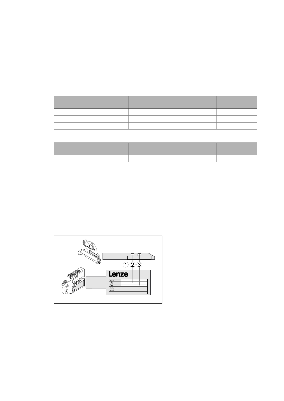
3.2 Identification
The type designation and the hardware and software versions of the communication module are
indicated on the nameplate:
version
version
From software
version
From software
version
[3-1] Identification data
12
1Type designation
E94 Product series
AVersion
Y Module identification: Extension module
C Module type: Communication module
ER PROFINET
2 Hardware version
3Software version
E94YCET005
Lenze · E94AYCER communication module (PROFINET®) · Communication Manual · DMS 9.0 EN · 12/2013 · TD17
Page 13

3 Product description
3.3 Product features
_ _ _ _ _ _ _ _ _ _ _ _ _ _ _ _ _ _ _ _ _ _ _ _ _ _ _ _ _ _ _ _ _ _ _ _ _ _ _ _ _ _ _ _ _ _ _ _ _ _ _ _ _ _ _ _ _ _ _ _ _ _ _ _
3.3 Product features
• Interface module for the PROFINET IO communication system, for attaching to the expansion
slots of Servo Drives 9400
• The communication module can either be supplied internally by the standard device or
externally by a separate voltage source.
• Support of the I&M0...4 functionality for the identification of the standard device
• Automatic detection of the baud rate 100 Mbps
• A line topology is enabled by the integrated 2-port switch.
• Support of the LLDP (Link Layer Discovery Protocol) for the topology recognition
• Support of the SNMP (Simple Network Management Protocol) for diagnostic purposes
• Transfer of safe information via the PROFIsafe protocol if an SM301 safety module (E94AYAE) is
used simultaneously
• Up to 32 process data words (64 bytes) per direction can be exchanged.
• Access to all Lenze parameters
• An online connection via PROFINET can be established using the Lenze »Engineer«.
Lenze · E94AYCER communication module (PROFINET®) · Communication Manual · DMS 9.0 EN · 12/2013 · TD17 13
Page 14
3 Product description
3.4 Terminals and interfaces
_ _ _ _ _ _ _ _ _ _ _ _ _ _ _ _ _ _ _ _ _ _ _ _ _ _ _ _ _ _ _ _ _ _ _ _ _ _ _ _ _ _ _ _ _ _ _ _ _ _ _ _ _ _ _ _ _ _ _ _ _ _ _ _
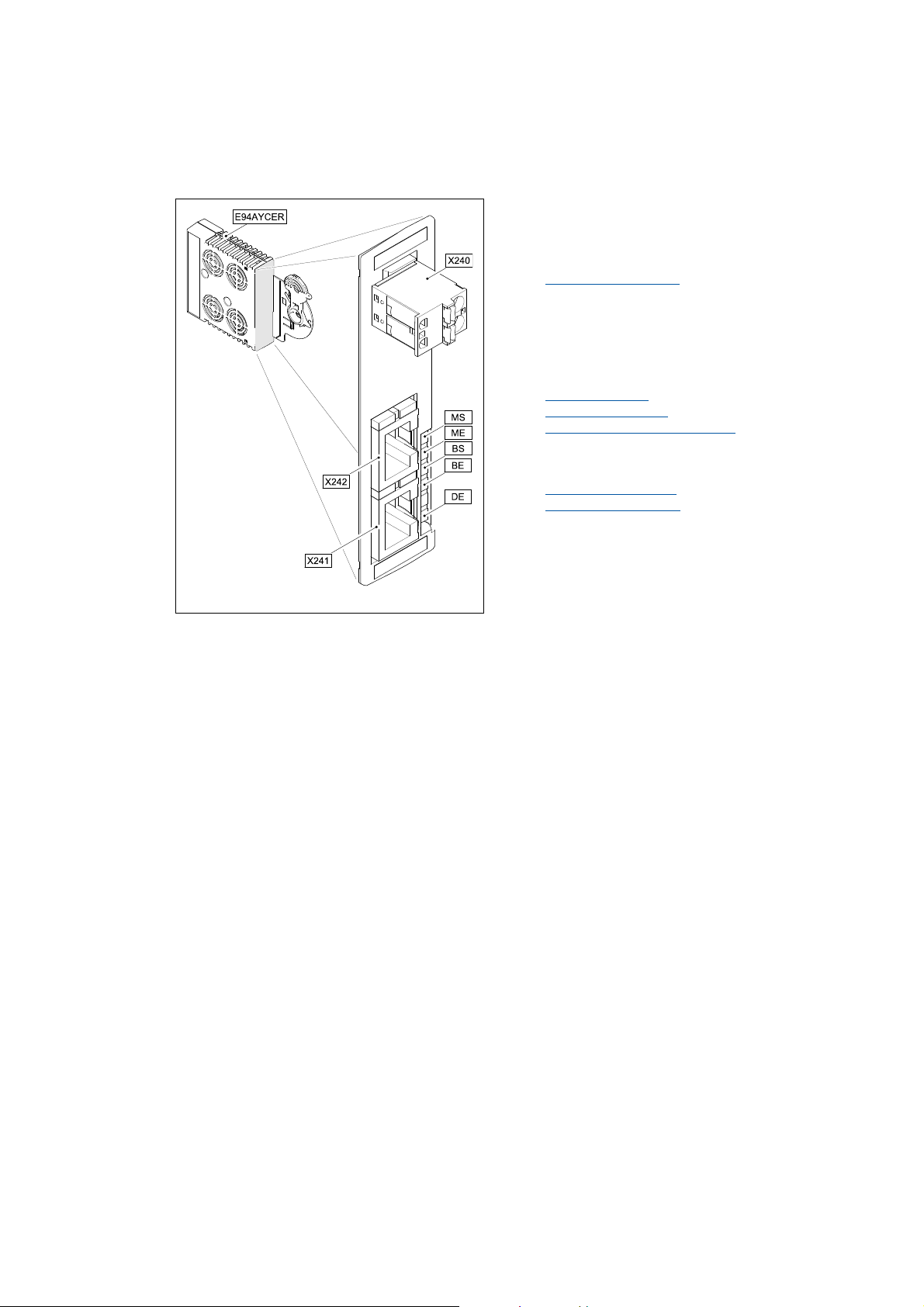
3.4 Terminals and interfaces
X240 External voltage supply of the communication
module
• 2-pin plug connector with spring connection
External voltage supply
X241 PROFINET input (IN)
X242 PROFINET output (OUT)
• RJ45 sockets according to IEC/EN 60603-7
• each with 2 LED status displays for diagnostics
Network topology
PROFINET connection
Status displays at X241 and X242
LED status displays for diagnostic purposes
MS
Module status displays
ME
BS
Fieldbus status displays
BE
DE
( 31)
( 25)
( 27)
( 80)
( 78)
( 79)
E94YCER001B
[3-2] E94AYCER communication module (PROFINET)
14
Lenze · E94AYCER communication module (PROFINET®) · Communication Manual · DMS 9.0 EN · 12/2013 · TD17
Page 15

4Technical data
4.1 General data and operating conditions
_ _ _ _ _ _ _ _ _ _ _ _ _ _ _ _ _ _ _ _ _ _ _ _ _ _ _ _ _ _ _ _ _ _ _ _ _ _ _ _ _ _ _ _ _ _ _ _ _ _ _ _ _ _ _ _ _ _ _ _ _ _ _ _
4 Technical data
4.1 General data and operating conditions
Range Values
Order designation E94AYCER
Communication profile PROFINET
Communication medium S/FTP (Screened Foiled Twisted Pair, ISO/IEC 11801 or EN 50173), CAT 5e
Interface for communication RJ45: Standard Ethernet (in accordance with IEEE 802.3), 100Base-TX (Fast
Ethernet)
Network topology Tree, star, and line
Type of node IO device with real time (RT) communication properties
Number of device nodes Max. 255 in the subnetwork
Max. cable length 100 m
PNO identification number 0x0106
Device identification (Device ID) 0x9400
TCP port 9410
Baud rate 100 Mbps
Switching method "Store and forward"
Switch latency Approx. 125 μs at max. telegram length
Voltage supply External supply via a separate power supply unit
+: U = 24 V DC (20.4 V ... 28.8 V), I = 130 mA
- : Reference potential for external voltage supply
Conformities, approvals • CE
•UL
(see also hardware manual)
Servo Drives 9400 hardware manual
Here you can find the ambient conditions and data on the electromagnetic compatibility
(EMC), which also apply to the communication module.
Lenze · E94AYCER communication module (PROFINET®) · Communication Manual · DMS 9.0 EN · 12/2013 · TD17 15
Page 16
4Technical data
4.2 Protocol data
_ _ _ _ _ _ _ _ _ _ _ _ _ _ _ _ _ _ _ _ _ _ _ _ _ _ _ _ _ _ _ _ _ _ _ _ _ _ _ _ _ _ _ _ _ _ _ _ _ _ _ _ _ _ _ _ _ _ _ _ _ _ _ _
4.2 Protocol data
Range Values
Process data words (PCD) Maximally 32 process data words (max. 64 bytes)
PROFIsafe message 4 words (8 bytes)
Acyclic parameter data channel Limited by the PROFINET frame size
4.3 Communication time
The communication time is the time between the start of a request and the arrival of the
corresponding response.
The communication times in an PROFINET network depend on the ...
• processing time in the inverter;
• telegram runtime (baud rate / telegram length);
• nesting depth of the network.
processing time within the inverter
Data Processing time
Process data (IO data) 10 ms
+ 0 ... 1 ms
Parameter data Approx. 30 ms + a tolerance of 20 ms (typically)
+ 1 ... x ms
Some codes may require a longer processing time (see reference manual/
»Engineer« online help for the Servo Drive 9400).
Lenze standard update cycle (can be changed in the Rockwell
engineering tool)
Processing time in the module
Runtime of the application task of the technology
application used (tolerance)
The times specified apply if the TCP/IP channel of the communication module is not used
(»Engineer« communication, chapter Setting the IP configuration
( 37)).
There are no interdependencies between parameter data and process data.
16
Lenze · E94AYCER communication module (PROFINET®) · Communication Manual · DMS 9.0 EN · 12/2013 · TD17
Page 17

4Technical data
4.4 Internal switch latency
_ _ _ _ _ _ _ _ _ _ _ _ _ _ _ _ _ _ _ _ _ _ _ _ _ _ _ _ _ _ _ _ _ _ _ _ _ _ _ _ _ _ _ _ _ _ _ _ _ _ _ _ _ _ _ _ _ _ _ _ _ _ _ _
4.4 Internal switch latency
The integrated 2-port switch causes runtime delays which can be calculated as follows:
Runtime delay = ((36 permanent bytes + process data in bytes) x 8 x 10 nsec) + 4 μsec
Example
20 process data words + 4 PROFIsafe words => 48 bytes
• ((36 permanent bytes + 48 bytes) x 8 x 10 nsec) + 4 μsec
• (84 bytes x 8 x 10 nsec) + 4 μsec
• 6.72 μsec + 4 μsec = 10.72 μsec
In accordance with the PROFINET specification, the shortest PROFINET IO telegram must have a data
length of 72 bytes. If the 36 permanent bytes are subtracted from the 72 bytes, 36 bytes are
available for process data. If now less than 36 bytes of process data are used, the PROFINET IO
telegram is filled with "zero bytes" until it can be transmitted. As a consequence for the calculation
formula, the shortest PROFINET IO telegram with 18 process data words (36 bytes) has always the
same length and thus the runtime delay is the same, too.
Note!
The use of external switches can also lead to runtime delays. Depending on the system
constellation, it may be useful to create a star topology or a line/mix topology.
Network topology
( 25)
Lenze · E94AYCER communication module (PROFINET®) · Communication Manual · DMS 9.0 EN · 12/2013 · TD17 17
Page 18

4Technical data
4.5 Protective insulation
_ _ _ _ _ _ _ _ _ _ _ _ _ _ _ _ _ _ _ _ _ _ _ _ _ _ _ _ _ _ _ _ _ _ _ _ _ _ _ _ _ _ _ _ _ _ _ _ _ _ _ _ _ _ _ _ _ _ _ _ _ _ _ _
4.5 Protective insulation
Danger!
Dangerous voltage
If the Servo Drives 9400 are operated on a phase earthed mains with a rated mains
voltage 400 V, external measures need to be implemented in order to ensure
protection against accidental contact.
Possible consequences:
Death or severe injuries
Protective measures:
If protection against accidental contact is required for the control terminals of the
inverter and the connections of the plugged device modules, ...
• a double isolating distance must exist.
• the components to be connected must be provided with the second isolating
distance.
Note!
The protective insulation provided in Servo Drives 9400 is implemented in accordance
with EN 61800-5-1.
18
Lenze · E94AYCER communication module (PROFINET®) · Communication Manual · DMS 9.0 EN · 12/2013 · TD17
Page 19
4Technical data
Ext. DC
I/O
X4
X6X6
X5
X7X7
X8X8
X3
X2
X1
X105X105
X106
X100
X107
MXI1
MXI2
Bus
Ext. DC
MSI
MMI
4.5 Protective insulation
_ _ _ _ _ _ _ _ _ _ _ _ _ _ _ _ _ _ _ _ _ _ _ _ _ _ _ _ _ _ _ _ _ _ _ _ _ _ _ _ _ _ _ _ _ _ _ _ _ _ _ _ _ _ _ _ _ _ _ _ _ _ _ _
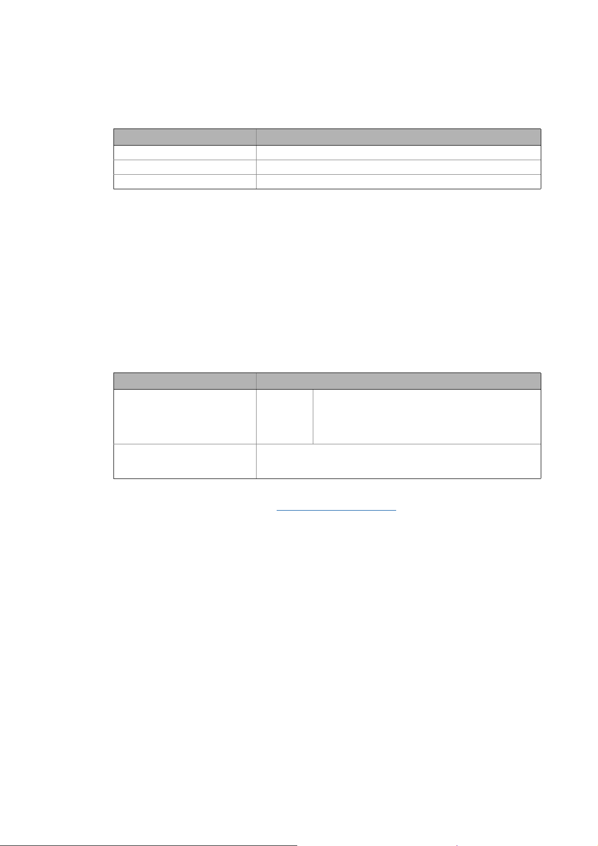
The following illustration ...
• shows the arrangement of the terminal strips and the separate potential areas of the Servo
Drive 9400.
• serves to determine the decisive protective insulation between two terminals located in
differently insulated separate potential areas.
Reinforced insulation
Basic insulation
Functional insulation
[4-1] Protective insulation in accordance with EN61800-5-1
Terminal strip Connection Terminal strip Connection
X100 L1, L2, L3 (Single Drive only) X1 CAN on board 9400
+UG, -UG X2 State bus
X105 U, V, W 24 V (ext.)
Rb1, Rb2 (Single Drive only) X3 Analog inputs/outputs
X106 Motor PTC X4 Digital outputs
X107 Control of the motor holding
brake
E94YCXX007
X5 Digital inputs
X6 Diagnostics
X7 Resolver
X8 Encoder
MXI1, MXI2 Extension module
MMI Memory module
MSI Safety module
Lenze · E94AYCER communication module (PROFINET®) · Communication Manual · DMS 9.0 EN · 12/2013 · TD17 19
Page 20

4Technical data
4.5 Protective insulation
_ _ _ _ _ _ _ _ _ _ _ _ _ _ _ _ _ _ _ _ _ _ _ _ _ _ _ _ _ _ _ _ _ _ _ _ _ _ _ _ _ _ _ _ _ _ _ _ _ _ _ _ _ _ _ _ _ _ _ _ _ _ _ _
Example
Which type of protective insulation is used between the bus terminal of the device module in slot
MXI1 or MXI2 and the mains terminal X100?
The separate potential area with the better protective insulation is decisive.
• The separate potential area of the bus terminal of the device module has a "functional
insulation".
• The separate potential area of the mains terminal has a "reinforced insulation".
Result: The insulation between mains terminal X100 and the bus terminal is of the "reinforced
insulation" type.
20
Lenze · E94AYCER communication module (PROFINET®) · Communication Manual · DMS 9.0 EN · 12/2013 · TD17
Page 21
4Technical data
4.6 Dimensions
_ _ _ _ _ _ _ _ _ _ _ _ _ _ _ _ _ _ _ _ _ _ _ _ _ _ _ _ _ _ _ _ _ _ _ _ _ _ _ _ _ _ _ _ _ _ _ _ _ _ _ _ _ _ _ _ _ _ _ _ _ _ _ _
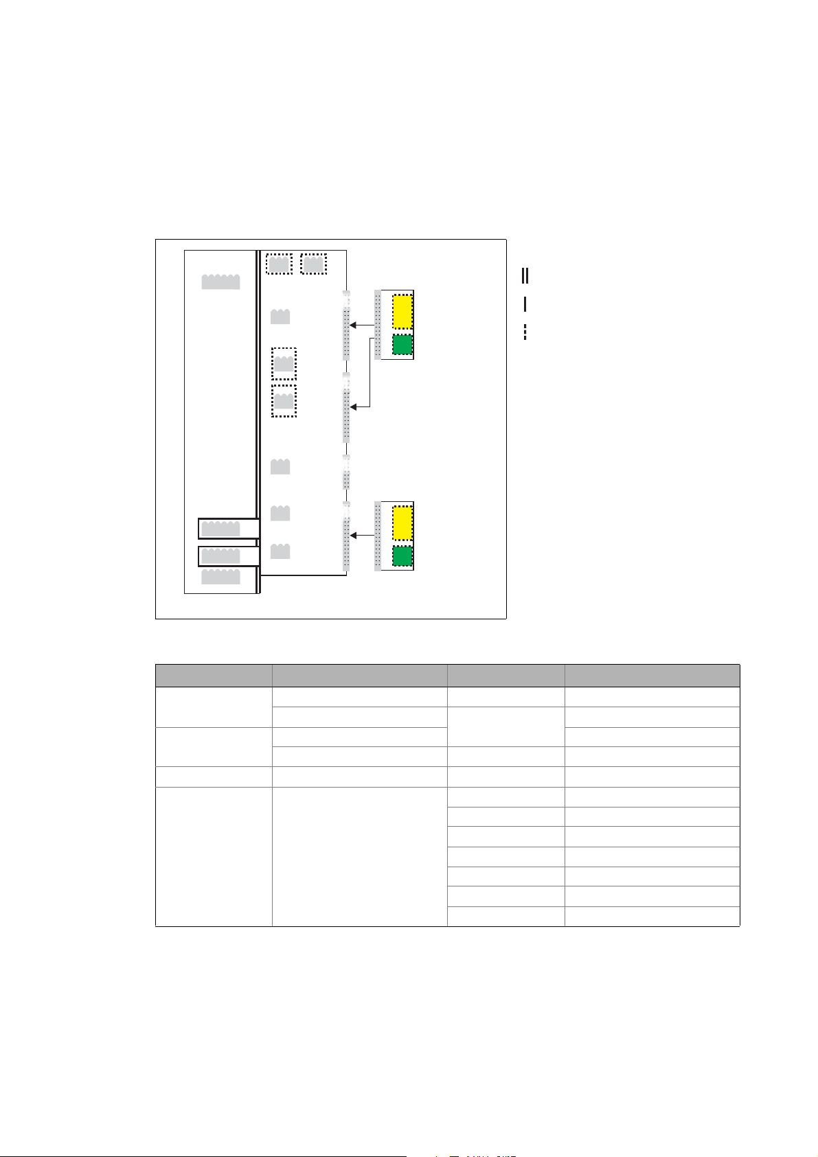
4.6 Dimensions
a 89 mm
b 134 mm
b1 87 mm
e 23 mm
[4-2] Dimensions
E94YCXX005
Lenze · E94AYCER communication module (PROFINET®) · Communication Manual · DMS 9.0 EN · 12/2013 · TD17 21
Page 22

5 Installation
_ _ _ _ _ _ _ _ _ _ _ _ _ _ _ _ _ _ _ _ _ _ _ _ _ _ _ _ _ _ _ _ _ _ _ _ _ _ _ _ _ _ _ _ _ _ _ _ _ _ _ _ _ _ _ _ _ _ _ _ _ _ _ _
5 Installation
Stop!
Electrostatic discharge
Electronic components within the communication module can be damaged or destroyed
by electrostatic discharge.
Possible consequences:
• The communication module is defective.
• Fieldbus communication is not possible or faulty.
Protective measures
• Before touching the module, be sure that you are free of electrostatic charge.
22 Lenze · E94AYCER communication module (PROFINET®) · Communication Manual · DMS 9.0 EN · 12/2013 · TD17
Page 23
5 Installation
5.1 Mechanical installation
_ _ _ _ _ _ _ _ _ _ _ _ _ _ _ _ _ _ _ _ _ _ _ _ _ _ _ _ _ _ _ _ _ _ _ _ _ _ _ _ _ _ _ _ _ _ _ _ _ _ _ _ _ _ _ _ _ _ _ _ _ _ _ _
5.1 Mechanical installation
Note!
A safety bus system (PROFIsafe) can only be operated via the upper module slot (MXI1)
of the Servo Drive 9400.
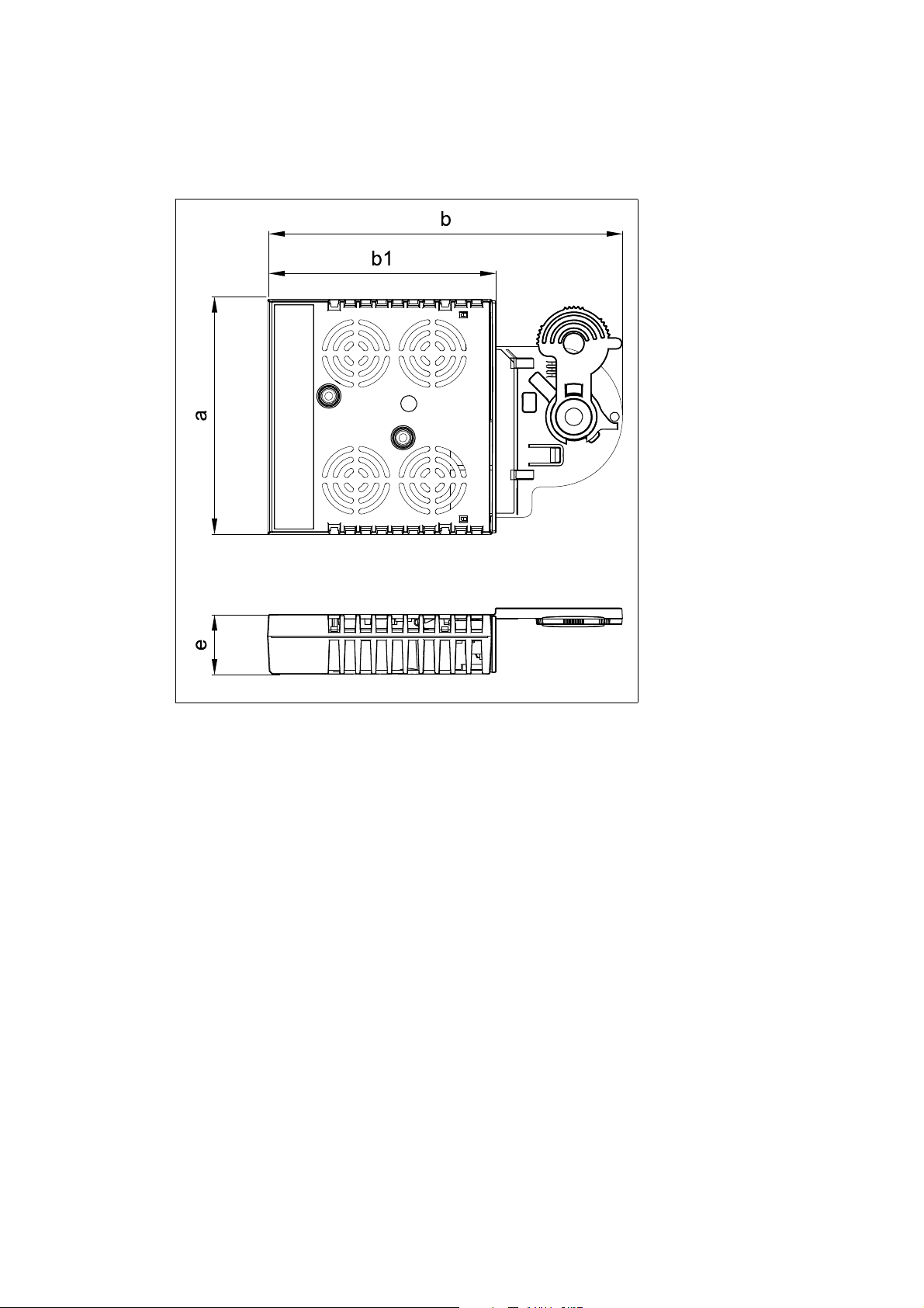
5.1.1 Assembly
[5-1] Assembly
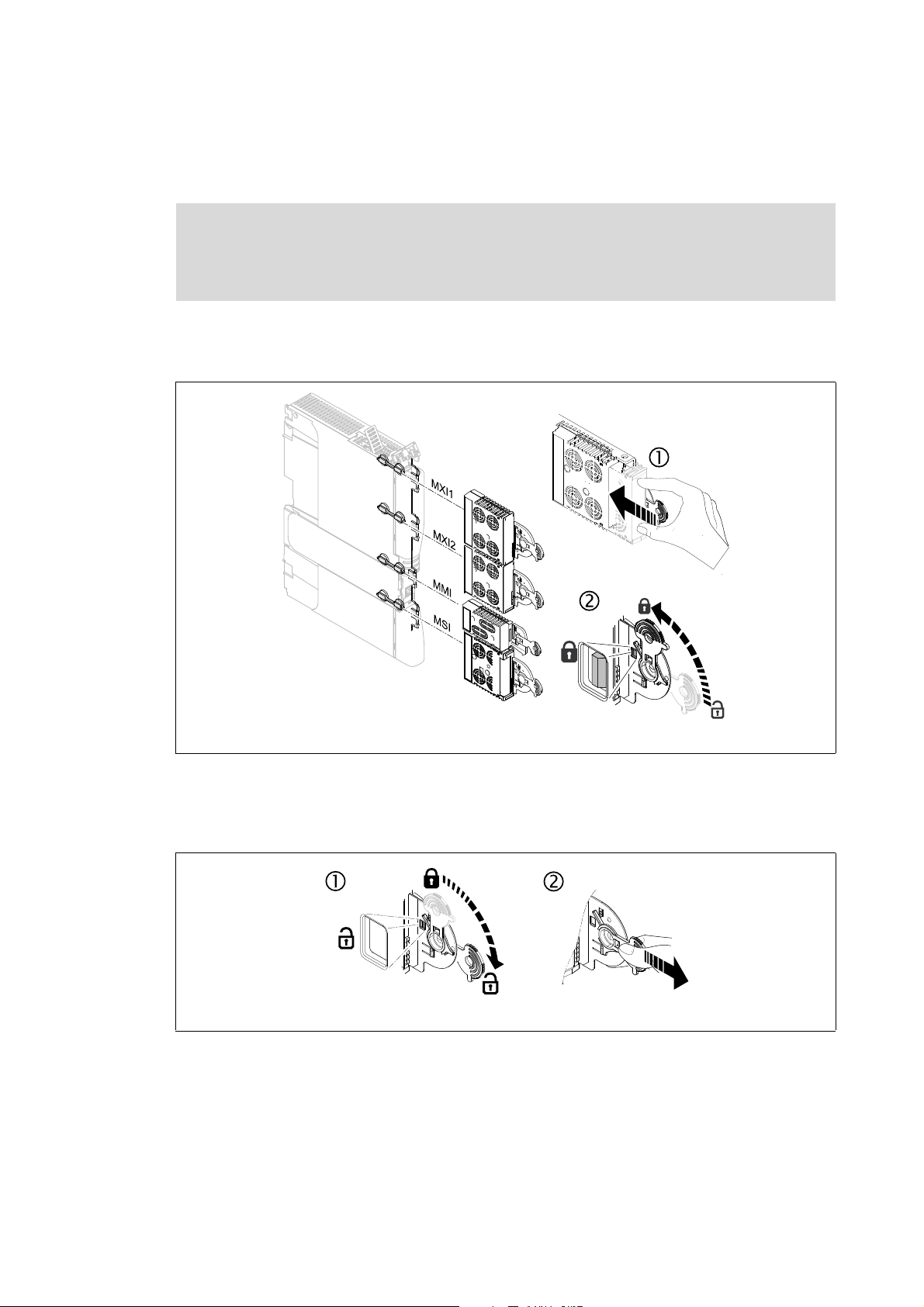
5.1.2 Disassembly
[5-2] Disassembly
E94YCXX001G
E94AYCXX001H
Lenze · E94AYCER communication module (PROFINET®) · Communication Manual · DMS 9.0 EN · 12/2013 · TD17 23
Page 24
5 Installation
5.2 Electrical installation
_ _ _ _ _ _ _ _ _ _ _ _ _ _ _ _ _ _ _ _ _ _ _ _ _ _ _ _ _ _ _ _ _ _ _ _ _ _ _ _ _ _ _ _ _ _ _ _ _ _ _ _ _ _ _ _ _ _ _ _ _ _ _ _
5.2 Electrical installation
Documentation for the standard device, control system, system/machine
Observe the notes and wiring instructions contained in this documentation.
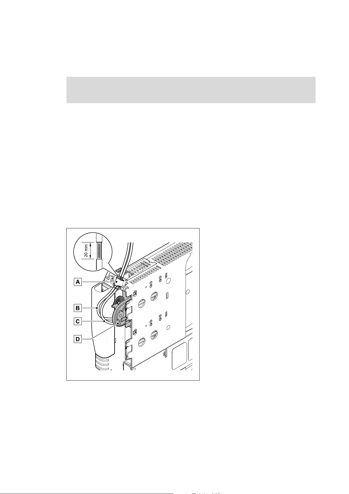
5.2.1 Wiring according to EMC guidelines
In typical systems, standard shielding is sufficient for Ethernet cables.
However, in environments with a very high level of interference, EMC resistance can be improved
by additionally earthing the cable shield on both sides.
For this observe the following notes:
1. The distance between the additional earthing and the Ethernet plug depends on the module
slot and is as follows:
• approx. 10 cm for the upper slot (MXI1)
• approx. 20 cm for the lower slot (MXI2)
2. Measure the appropriate distance along the cable and, starting from this point, remove 2 cm of
the cable's plastic sheath.
3. Connect the cable shield to the shield sheet of the Servo Drive 9400.
A Connection to the shield sheet of the Servo
Drive 9400
B Outgoing PROFINET cable at X242
C Incoming PROFINET cable at X241
D Communication module in slot MXI1 of the
Servo Drive 9400
E94YCXX008
[5-3] Wiring according to EMC guidelines
24
Lenze · E94AYCER communication module (PROFINET®) · Communication Manual · DMS 9.0 EN · 12/2013 · TD17
Page 25
5 Installation
S
D
DD
C
S
SS
SSS
5.2 Electrical installation
_ _ _ _ _ _ _ _ _ _ _ _ _ _ _ _ _ _ _ _ _ _ _ _ _ _ _ _ _ _ _ _ _ _ _ _ _ _ _ _ _ _ _ _ _ _ _ _ _ _ _ _ _ _ _ _ _ _ _ _ _ _ _ _
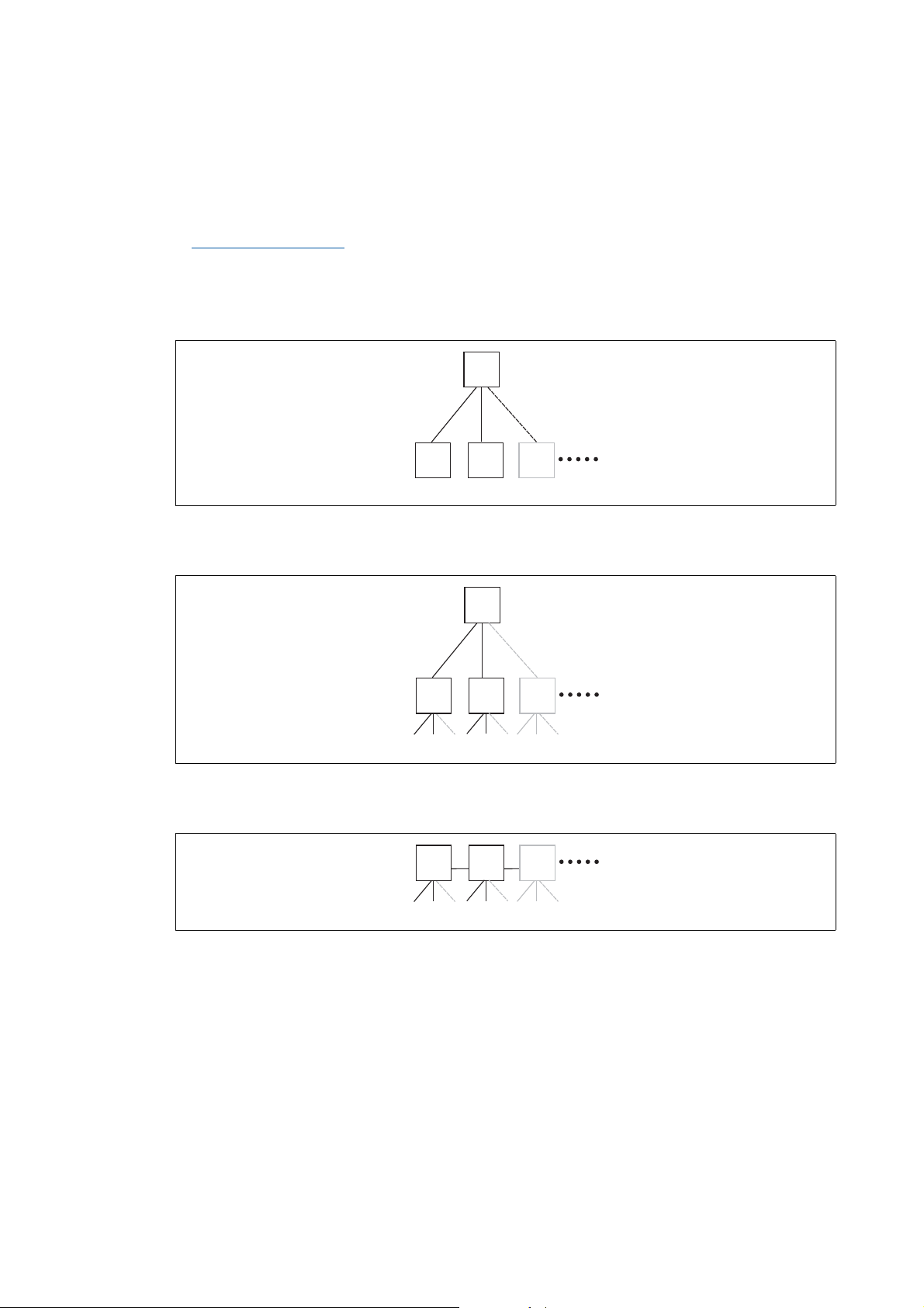
5.2.2 Network topology
It is typical of PROFINET to have a rather free topology the limiting factor of which is large message
latencies due to e.g. switches connected in series.
Internal switch latency
The combination of a line and a stub is useful for system wiring.
PROFINET supports the following topologies:
•Switch / star
( 17)
E94YCER005
[5-4] Switch / star topology (S = switch, D = IO device)
•Tree via switches
[5-5] Tree topology (C =IO controller, S = switch)
•Switch / switch
[5-6] Switch/switch topology (S = switch)
E94YCER006
E94YCER007
Lenze · E94AYCER communication module (PROFINET®) · Communication Manual · DMS 9.0 EN · 12/2013 · TD17 25
Page 26

5 Installation
D D D D
C
5.2 Electrical installation
_ _ _ _ _ _ _ _ _ _ _ _ _ _ _ _ _ _ _ _ _ _ _ _ _ _ _ _ _ _ _ _ _ _ _ _ _ _ _ _ _ _ _ _ _ _ _ _ _ _ _ _ _ _ _ _ _ _ _ _ _ _ _ _
• IO controller / IO device
E94YCER008
[5-7] Line topology (C = IO controller, D = IO device)
26
Lenze · E94AYCER communication module (PROFINET®) · Communication Manual · DMS 9.0 EN · 12/2013 · TD17
Page 27
5 Installation
5.2 Electrical installation
_ _ _ _ _ _ _ _ _ _ _ _ _ _ _ _ _ _ _ _ _ _ _ _ _ _ _ _ _ _ _ _ _ _ _ _ _ _ _ _ _ _ _ _ _ _ _ _ _ _ _ _ _ _ _ _ _ _ _ _ _ _ _ _
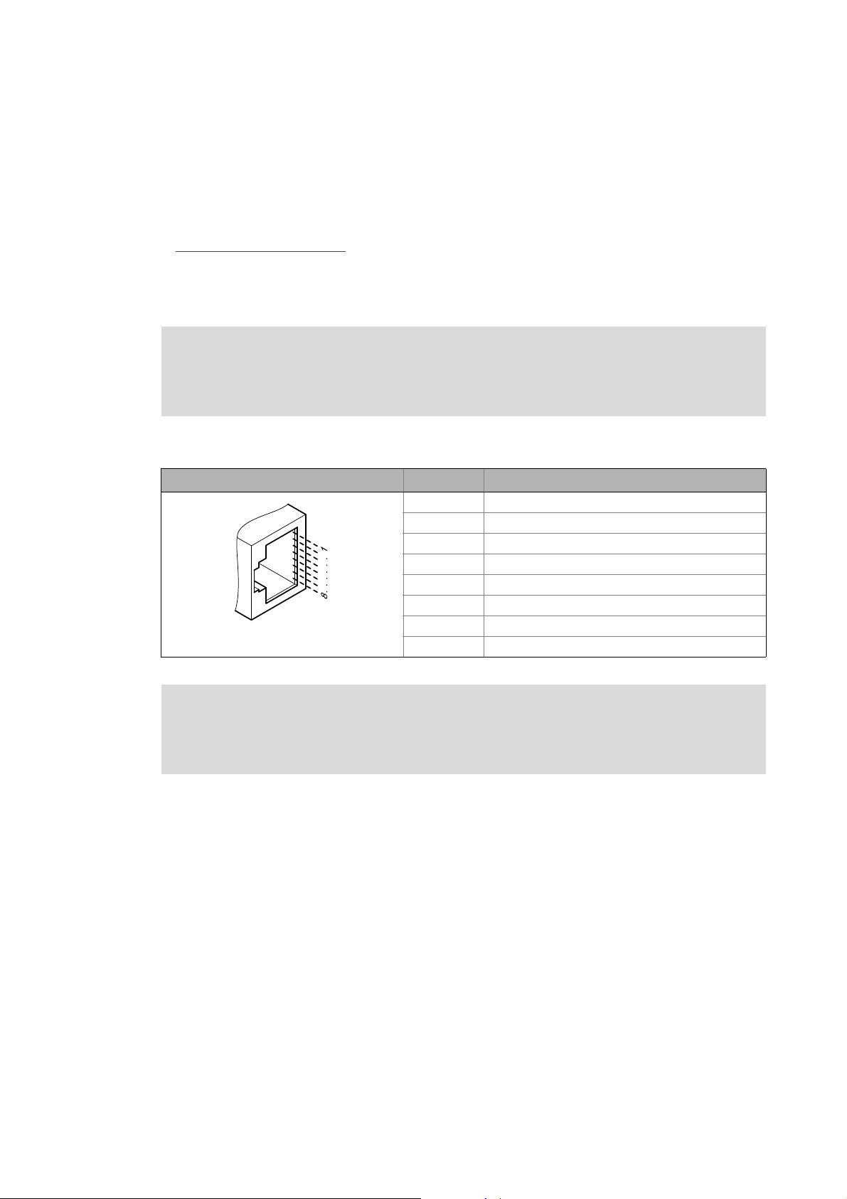
5.2.3 PROFINET connection
PROFINET is connected via the RJ45 sockets X241 and X242.
For connection of the communication module to the PROFINET fieldbus, a standard Ethernet patch
cable is suitable.
Ethernet cable specification
The installation and removal of the Ethernet cables is optimised for the use of connectors in
accordance with the "Automation Initiative of German Domestic Automobile Manufacturers"
(AIDA).
( 29)
Note!
To prevent the RJ45 socket from being damaged, insert or remove the Ethernet cable
connector straight (at a right angle) into or from the socket.
Pin assignment
RJ45 socket Pin Signal
1Tx +
2Tx -
3Rx +
4-
5-
6Rx -
E94AYCXX004C
7-
8-
Note!
Dependent on the configuration of the Ethernet port of the device to be connected, we
recommend the use of a cross-over cable.
Tip!
The PROFINET interfaces feature an auto-MDIX function. This function adjusts the polarity
of the RJ45 interfaces so that a connection can be established irrespective of the polarity of
the opposite PROFINET interface and irrespective of the type of cable used (standard patch
cable or crossover cable).
Lenze · E94AYCER communication module (PROFINET®) · Communication Manual · DMS 9.0 EN · 12/2013 · TD17 27
Page 28
5 Installation
5.2 Electrical installation
_ _ _ _ _ _ _ _ _ _ _ _ _ _ _ _ _ _ _ _ _ _ _ _ _ _ _ _ _ _ _ _ _ _ _ _ _ _ _ _ _ _ _ _ _ _ _ _ _ _ _ _ _ _ _ _ _ _ _ _ _ _ _ _
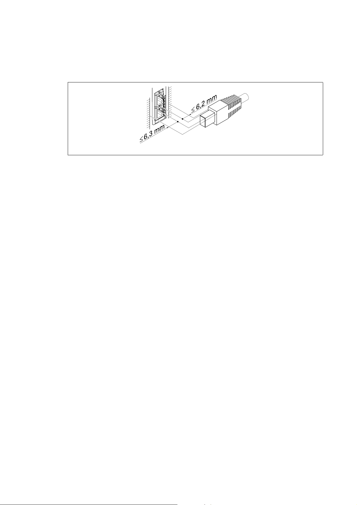
Mounting clearance
When ordering and using your Ethernet cable, note the amount of free space available.
E94YCET017
[5-8] Mounting clearance
28
Lenze · E94AYCER communication module (PROFINET®) · Communication Manual · DMS 9.0 EN · 12/2013 · TD17
Page 29
5 Installation
5.2 Electrical installation
_ _ _ _ _ _ _ _ _ _ _ _ _ _ _ _ _ _ _ _ _ _ _ _ _ _ _ _ _ _ _ _ _ _ _ _ _ _ _ _ _ _ _ _ _ _ _ _ _ _ _ _ _ _ _ _ _ _ _ _ _ _ _ _
5.2.4 Ethernet cable specification
Note!
Only use cables that meet the listed specifications.
Ethernet cable specification
Ethernet standard Standard Ethernet (in accordance with IEEE 802.3), 100Base-TX (Fast
Cable type S/FTP (Screened Foiled Twisted Pair, ISO/IEC 11801 or EN 50173), CAT 5e
Damping 23.2 dB (for 100 MHz and 100 m each)
Crosstalk damping 24 dB (at 100 MHz and per 100 m)
Return loss 10 dB (per 100 m)
Surge impedance 100
Ethernet)
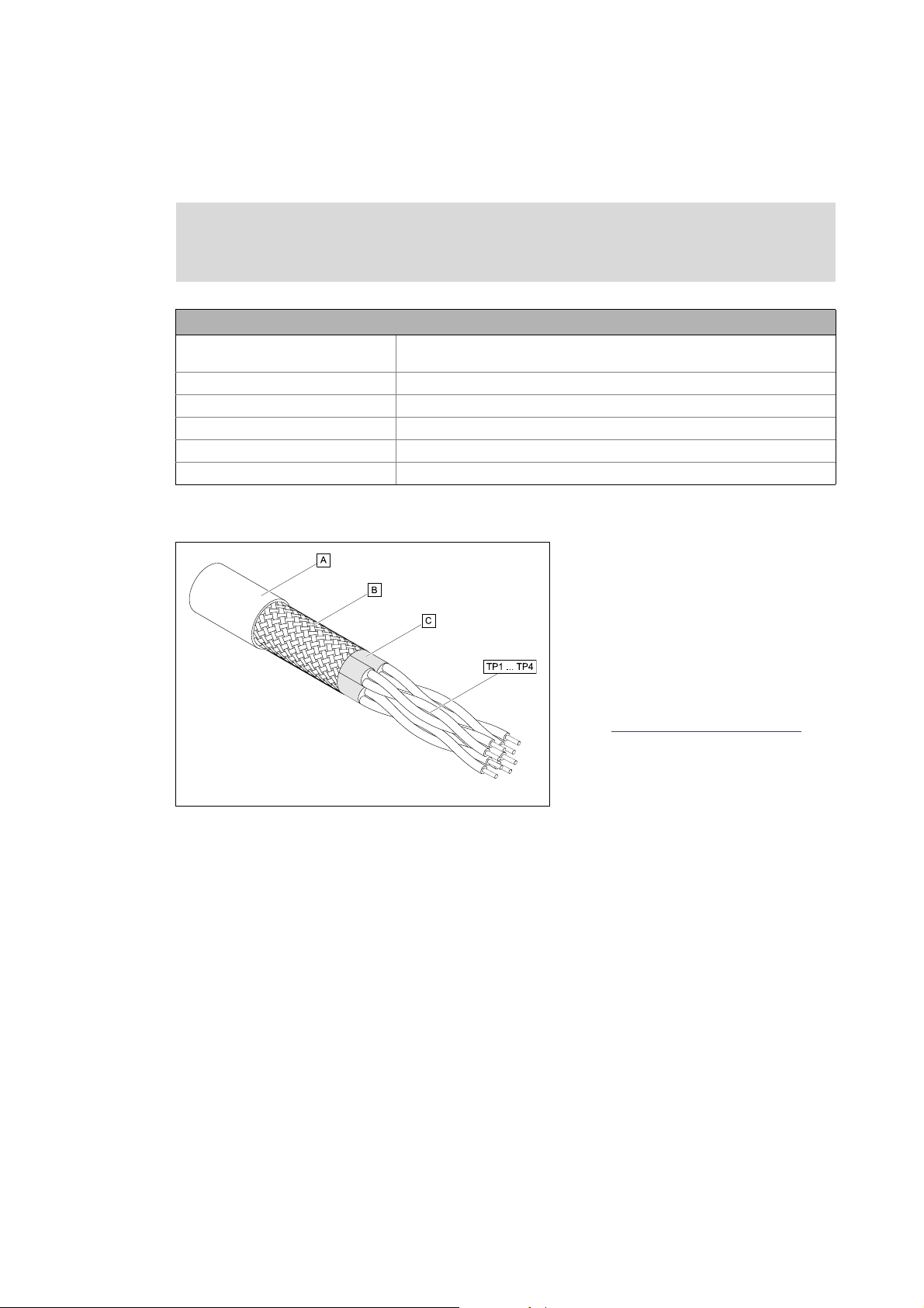
Structure of the Ethernet cable
[5-9] Structure of the Ethernet cable (S/FTP, CAT 5e)
E94YCEP016
A Cable insulation
B Braid
C Foil shielding
TP1
Twisted core pairs 1 ... 4
...
Colour code of the Ethernet cable
TP4
( 30)
Lenze · E94AYCER communication module (PROFINET®) · Communication Manual · DMS 9.0 EN · 12/2013 · TD17 29
Page 30
5 Installation
5.2 Electrical installation
_ _ _ _ _ _ _ _ _ _ _ _ _ _ _ _ _ _ _ _ _ _ _ _ _ _ _ _ _ _ _ _ _ _ _ _ _ _ _ _ _ _ _ _ _ _ _ _ _ _ _ _ _ _ _ _ _ _ _ _ _ _ _ _
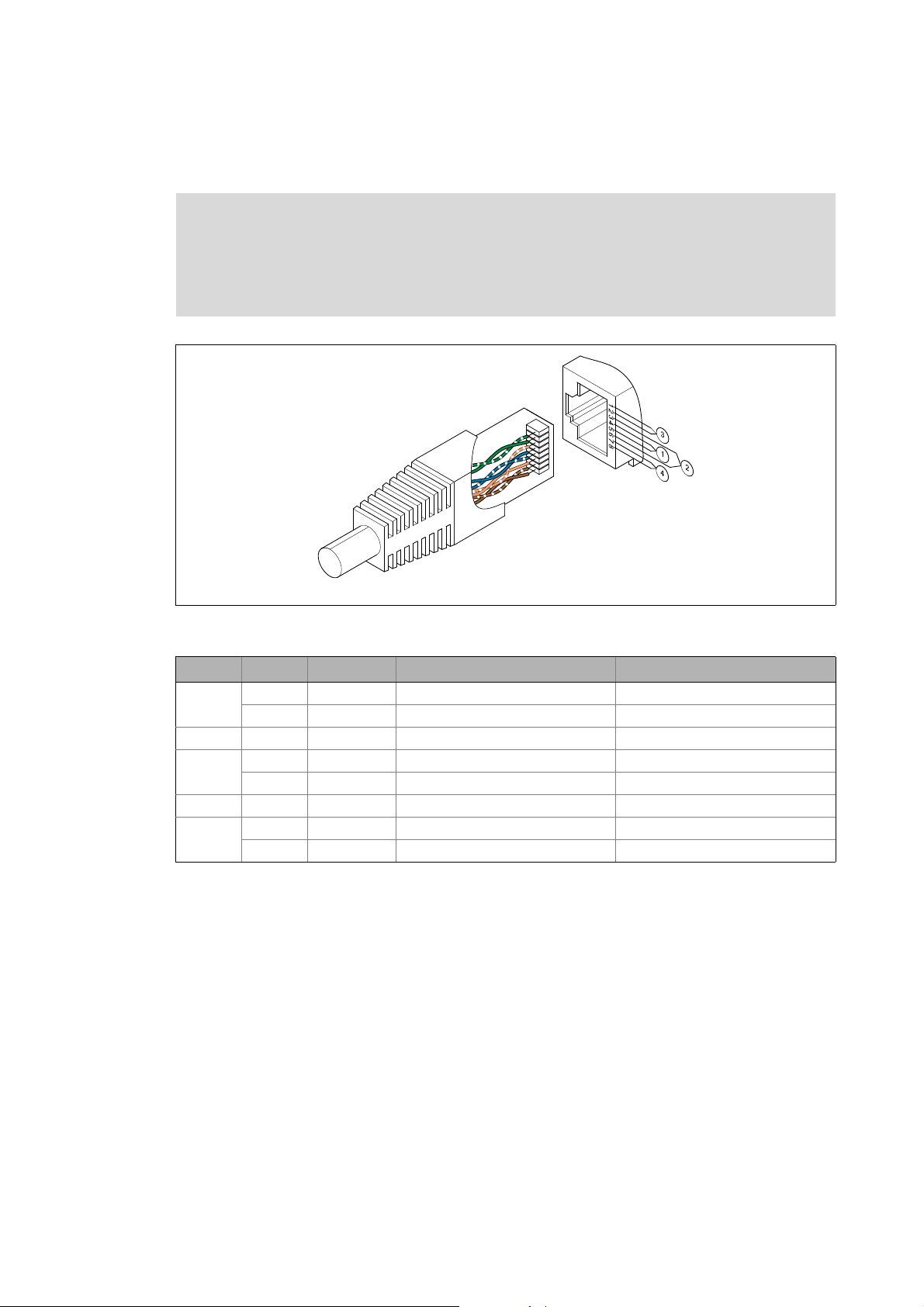
Colour code of the Ethernet cable
Note!
Wiring and colour code are standardised in EIA/TIA 568A/568B.
In accordance with the industrial standard, the use of 4-pin Ethernet cables is
permissible. The cable type only connects the assigned pins 1, 2, 3 and 6 to one another.
E94YCEI004A
[5-10] Ethernet plug in accordance with EIA/TIA 568A/568B
Pair Pin Signal EIA/TIA 568A EIA/TIA 568B
3 1 Tx + white / green white / orange
2 Tx - green orange
2 3 Rx + white / orange white / green
1 4 blue blue
5 white / blue blue / white
2 6 Rx - orange green
4 7 white / brown white / brown
8brown brown
30
Lenze · E94AYCER communication module (PROFINET®) · Communication Manual · DMS 9.0 EN · 12/2013 · TD17
Page 31

5 Installation
5.2 Electrical installation
_ _ _ _ _ _ _ _ _ _ _ _ _ _ _ _ _ _ _ _ _ _ _ _ _ _ _ _ _ _ _ _ _ _ _ _ _ _ _ _ _ _ _ _ _ _ _ _ _ _ _ _ _ _ _ _ _ _ _ _ _ _ _ _
5.2.5 External voltage supply
The communication module can be supplied externally with voltage via separate supply cables at
the 2-pole plug connector X240.
Note!
With external voltage supply, always use a separate power supply unit, safely separated
to EN 61800-5-1 in every control cabinet (SELV/PELV).
External voltage supply of the communication module is required if the communication via the bus
should be maintained when the supply of the standard device fails.
The parameters of a standard device separated from the mains cannot be accessed.
Assignment of plug connector X240
Designation Description
+ U = 24 V DC (20.4 ... 28.8 V)
I = 130 mA
- Reference potential for the external voltage supply
Terminal data
Range Values
Electrical connection 2-pin plug connector with spring connection
Possible connections Rigid:
2
1.5 mm
Flexible:
Without wire end ferrule
1.5 mm
With wire end ferrule, without plastic sleeve
1.5 mm
With wire end ferrule, with plastic sleeve
1.5 mm
Stripping length 9 mm
(AWG 16)
2
(AWG 16)
2
(AWG 16)
2
(AWG 16)
Lenze · E94AYCER communication module (PROFINET®) · Communication Manual · DMS 9.0 EN · 12/2013 · TD17 31
Page 32

6 Commissioning
6.1 Before initial switch-on
_ _ _ _ _ _ _ _ _ _ _ _ _ _ _ _ _ _ _ _ _ _ _ _ _ _ _ _ _ _ _ _ _ _ _ _ _ _ _ _ _ _ _ _ _ _ _ _ _ _ _ _ _ _ _ _ _ _ _ _ _ _ _ _
6 Commissioning
During commissioning, plant-specific data such as motor parameters, operating parameters,
responses, and parameters for fieldbus communication are defined for the inverter. Lenze devices
use codes for this purpose.
The codes of the inverter and for communication are saved to the memory module in a non-volatile
data set.
In addition, there are codes for diagnosing and monitoring the stations.
Parameter reference
Note!
When parameterising the communication module, please note that the code number
depends on the slot of the standard device into which the communication module is
plugged.
The first two digits of the code number indicate the slot:
•C13nnn for slot MXI1
Parameters of the communication module for slot MXI1
•C14nnn for slot MXI2
Parameters of the communication module for slot MXI2
You also have to set the Parameters of the standard device that are relevant to
communication ( 89).
6.1 Before initial switch-on
Stop!
( 89)
( 91)
( 101)
Before switching on the Servo Drive 9400 and the communication module for the first
time, check the entire wiring for completeness, short circuit and earth fault.
32
Lenze · E94AYCER communication module (PROFINET®) · Communication Manual · DMS 9.0 EN · 12/2013 · TD17
Page 33

6 Commissioning
6.2 Configuring the PROFINET IO controller
_ _ _ _ _ _ _ _ _ _ _ _ _ _ _ _ _ _ _ _ _ _ _ _ _ _ _ _ _ _ _ _ _ _ _ _ _ _ _ _ _ _ _ _ _ _ _ _ _ _ _ _ _ _ _ _ _ _ _ _ _ _ _ _
6.2 Configuring the PROFINET IO controller
To enable communication with the Servo Drive 9400, you have to configure the IO controller first.
Configuration for device control
For the configuration of PROFINET, the current PROFINET device description file (XML) of the
E94AYCER communication module (PROFINET) has to be imported in the IO controller.
The device description file GSDML-Vx.z-Lenze-9400PNabb-yyyymmdd.xml can be found in the
download area at:
www.lenze.com
Wildcards in the file name "GSDML-Vx.z-Lenze-9400PNabb-yyyymmdd.xml"
x Main version of the GSDML scheme used
z Subversion of the GSDML scheme used
a Major version of the software version
bb Minor version of the software version
yyyy Year
mm Month
dd Day
Defining the user data length
The user data length is defined during the initialisation phase of the IO controller.
Servo Drives 9400 HighLine support the configuration of max. 32 process data words (max.
64 bytes).
Description of the device data base file
Selection text Parameter data
(with consistency)
PCD (nW) AR cons. - n words n words
Safety (4W) AR - 4 words 4 words
n = 1 ... 32 process data words
Process data
(with consistency)
Assigned
IO memory
Lenze · E94AYCER communication module (PROFINET®) · Communication Manual · DMS 9.0 EN · 12/2013 · TD17 33
Page 34

6 Commissioning
6.2 Configuring the PROFINET IO controller
_ _ _ _ _ _ _ _ _ _ _ _ _ _ _ _ _ _ _ _ _ _ _ _ _ _ _ _ _ _ _ _ _ _ _ _ _ _ _ _ _ _ _ _ _ _ _ _ _ _ _ _ _ _ _ _ _ _ _ _ _ _ _ _
Example of selecting the device data base file
• "PCD (8W) AR cons." = 8 process data words (only in slot 1 of the PROFINET telegram)
• "Safety (4W) AR" = 4 safety data words (only in slot 2 of the PROFINET telegram)
Note!
A safety bus system (PROFIsafe) can only be operated via the upper module slot (MXI1)
of the Servo Drive 9400.
Tip!
A detailed description of consistency is given in the chapter "Consistent parameter data
( 73).
"
34
Lenze · E94AYCER communication module (PROFINET®) · Communication Manual · DMS 9.0 EN · 12/2013 · TD17
Page 35

6 Commissioning
6.3 Setting the station name
_ _ _ _ _ _ _ _ _ _ _ _ _ _ _ _ _ _ _ _ _ _ _ _ _ _ _ _ _ _ _ _ _ _ _ _ _ _ _ _ _ _ _ _ _ _ _ _ _ _ _ _ _ _ _ _ _ _ _ _ _ _ _ _
6.3 Setting the station name
Note!
• The "Node blinking test" PROFINET function by means of which an accessible field
device can be identified is supported. During execution of the function, the red LED
ME (Module status displays
• Operation of PROFINET requires a valid station name.
• In the case of impermissible settings, the red BE ( Fieldbus status displays
and the error message PROFINET: Invalid station name [0x00c86532]
The communication module then continues to work internally with the name deleted.
• If the station name is assigned by the IO controller via PROFINET or via the PROFINET
configurator of the »Engineer«, changes will become effective immediately.
The station name currently used is shown in code C13864 / C14864.
The station name ...
• is required for unambiguous addressing of the Servo Drive 9400 by the IO controller.
• can either be assigned by the IO controller via PROFINET or set manually in the »Engineer«.
( 78)) blinks.
( 79)) blinks
( 86) is output.
• has to be allocated in accordance with the PROFINET specification:
• 1 or several labels separated by ".".
• Max. length per label: 63 characters
• Max. total length: 240 characters
• Permissible characters: [a ... z], [0 ... 9], [.], [-]
• Labels must not begin or end with [-].
• Prohibited syntax:
• "n.n.n.n" (n = 0 ... 999)
• "port-xyz" (x, y, z = 0 ... 9)
• "port-xyz-abcde" (a,b,c,d,e,x,y,z=0...9)
Lenze · E94AYCER communication module (PROFINET®) · Communication Manual · DMS 9.0 EN · 12/2013 · TD17 35
Page 36

6 Commissioning
6.3 Setting the station name
_ _ _ _ _ _ _ _ _ _ _ _ _ _ _ _ _ _ _ _ _ _ _ _ _ _ _ _ _ _ _ _ _ _ _ _ _ _ _ _ _ _ _ _ _ _ _ _ _ _ _ _ _ _ _ _ _ _ _ _ _ _ _ _
In the »Engineer« the station name is set under the Settings tab.
The station name is written to code C13899
In the Lenze setting a deleted name is displayed. The name is also deleted if the "Reset to factory
defaults" command is executed by an IO supervisor or an IO controller.
/ C14899.
How to activate changed settings in the »Engineer«:
1. Execute the device command C00002 = "11: Save start parameters".
2. Carry out a "Reset node" of the node, or
module off and then on again
switch the voltage supply of the communication
36
Lenze · E94AYCER communication module (PROFINET®) · Communication Manual · DMS 9.0 EN · 12/2013 · TD17
Page 37

6 Commissioning
6.4 Setting the IP configuration
_ _ _ _ _ _ _ _ _ _ _ _ _ _ _ _ _ _ _ _ _ _ _ _ _ _ _ _ _ _ _ _ _ _ _ _ _ _ _ _ _ _ _ _ _ _ _ _ _ _ _ _ _ _ _ _ _ _ _ _ _ _ _ _
6.4 Setting the IP configuration
The IP configuration is required for addressing the Servo Drive 9400 in the PROFINET network. For
this purpose, an IP address, subnet mask and gateway address have to be allocated.
If no PROFINET network or IO controller is available yet, you can allocate the IP address, subnet
mask, and gateway address for the communication module by using the following options:
• Setting via the PROFINET configurator of the »Engineer«
• Setting via codes in the »Engineer«
( 40)
( 38)
• Setting via Siemens »STEP7« (»HW Konfig«)
• Setting via the Siemens »Primary Setup Tool«
Note!
• If the IP parameters are assigned by the IO Controller via the PROFINET, the PROFINET
configurator of the »Engineer«, Siemens »STEP7« or the Siemens »Primary Setup
Tool«, the changes become effective immediately and are saved with mains failure
protection.
• The assignment of invalid combinations of the IP address, subnet mask, and gateway
address can have the consequence that no connection to PROFINET can be
established.
• In the case of impermissible settings, the red LED BE (Fieldbus status displays
blinks and the error message PROFINET: Invalid IP parameters [0x00c86533]
output.
( 43)
( 47)
( 79))
( 87) is
Lenze · E94AYCER communication module (PROFINET®) · Communication Manual · DMS 9.0 EN · 12/2013 · TD17 37
Page 38
6 Commissioning
6.4 Setting the IP configuration
_ _ _ _ _ _ _ _ _ _ _ _ _ _ _ _ _ _ _ _ _ _ _ _ _ _ _ _ _ _ _ _ _ _ _ _ _ _ _ _ _ _ _ _ _ _ _ _ _ _ _ _ _ _ _ _ _ _ _ _ _ _ _ _
6.4.1 Setting via the PROFINET configurator of the »Engineer«
Note!
• The IP address must only be allocated manually in the »Engineer« if the PROFINET
network is not operated on the IO controller yet (IP address has not been allocated by
the IO controller yet).
• While setting the IP parameters in the »Engineer«, PROFINET communication with the
IO controller must not take place at the same time.
• Changes become effective immediately and are saved with mains failure protection.
• The currently used parameter values are shown in codes C13010
address), C13011
/ C14011 (subnet mask), and C13012 / C14012 (gateway address).
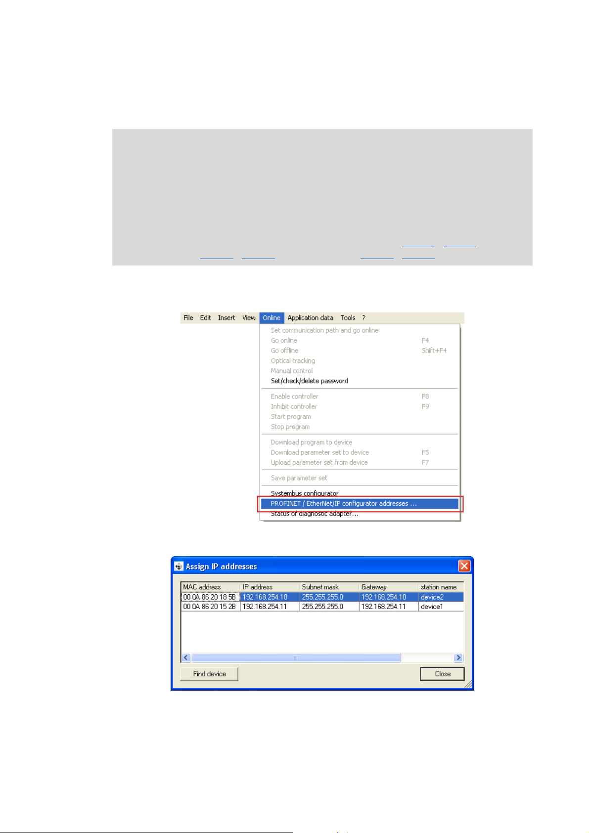
How to set the IP parameters via the PROFINET configurator:
1. Execute the menu command Online PROFINET / EtherNet/IP configurator addresses ....
/ C14010 (IP
The "Assign IP addresses" dialog window is opened and all Lenze PROFINET nodes
connected are listed.
38
Lenze · E94AYCER communication module (PROFINET®) · Communication Manual · DMS 9.0 EN · 12/2013 · TD17
Page 39

6 Commissioning
6.4 Setting the IP configuration
_ _ _ _ _ _ _ _ _ _ _ _ _ _ _ _ _ _ _ _ _ _ _ _ _ _ _ _ _ _ _ _ _ _ _ _ _ _ _ _ _ _ _ _ _ _ _ _ _ _ _ _ _ _ _ _ _ _ _ _ _ _ _ _
2. By double-clicking on the individual IP parameters, you can set the IP configuration for each
PROFINET node in the 'Configure nodes' dialog window.
3. Click the Transferred button.
• The IP configuration is transferred to the corresponding PROFINET node.
• Changes in the IP parameters will become effective immediately.
• The IP parameters are written to codes C13000
(subnet mask) and C13002
/ C14002 (gateway address).
/ C14000 (IP address), C13001 / C14001
Tip!
By clicking the Find device in the 'Assign IP addresses' dialog window (see step 1) you can
check whether the configuration has been transferred successfully.
With device command C00002 = "11: Save start parameters" , the current IP configuration
is saved non-volatilely in the memory module.
Lenze · E94AYCER communication module (PROFINET®) · Communication Manual · DMS 9.0 EN · 12/2013 · TD17 39
Page 40

6 Commissioning
6.4 Setting the IP configuration
_ _ _ _ _ _ _ _ _ _ _ _ _ _ _ _ _ _ _ _ _ _ _ _ _ _ _ _ _ _ _ _ _ _ _ _ _ _ _ _ _ _ _ _ _ _ _ _ _ _ _ _ _ _ _ _ _ _ _ _ _ _ _ _
6.4.2 Setting via codes in the »Engineer«
Note!
• The IP address must only be allocated manually in the »Engineer« if the PROFINET
network is not operated on the IO controller yet (IP address has not been allocated by
the IO controller yet).
• While setting the IP parameters in the »Engineer«, PROFINET communication with the
IO controller must not take place at the same time.
• The currently used parameter values are shown in codes C13010
address), C13011
In the »Engineer« under the Settings tab you can set the IP parameters manually via code.
/ C14011 (subnet mask), and C13012 / C14012 (gateway address).
/ C14010 (IP
The IP parameters are written to codes C13000
mask) and C13002
/ C14002 (gateway address).
How to activate changed settings in the »Engineer«:
1. Execute the device command C00002 = "11: Save start parameters".
2. Carry out a "Reset node" of the node, or
module off and then on again
/ C14000 (IP address), C13001 / C14001 (subnet
switch the voltage supply of the communication
40
Lenze · E94AYCER communication module (PROFINET®) · Communication Manual · DMS 9.0 EN · 12/2013 · TD17
Page 41

6 Commissioning
6.4 Setting the IP configuration
_ _ _ _ _ _ _ _ _ _ _ _ _ _ _ _ _ _ _ _ _ _ _ _ _ _ _ _ _ _ _ _ _ _ _ _ _ _ _ _ _ _ _ _ _ _ _ _ _ _ _ _ _ _ _ _ _ _ _ _ _ _ _ _
Decimal representation of the IP parameters
By clicking the [int] buttons on the right next to the input fields, the IP parameters are shown as a
decimal value.
In the case of the decimal representation, the byte sequence is inverted.
Example: IP address 192.168.0.1
C13000
0 0 0 0 0 0 0 1 0 0 0 0 0 0 0 0 1 0 1 0 1 0 0 0 1 1 0 0 0 0 0 0
/ C14000 = 16820416 [binary: 00000001.00000000.10101000.11000000]
Byte 3 Byte 2 Byte 1 Byte 0
1 0 168 192
C13010/4
C14010/4
C13010/3
C14010/3
C13010/2
C14010/2
C13010/1
C14010/1
IP address
Valid IP addresses are defined in accordance with RFC 3330.
The IP address is set/changed in C13000
In C13010/1...4
Example: Display of the IP address 192.168.0.1
Code C13010/1
Value 192 168 0 1
/ C14010/1...4 the currently used IP address is shown.
C14010/1
/ C14000.
C13010/2
C14010/2
C13010/3
C14010/3
C13010/4
C14010/4
Subnet mask
The subnet mask indicates which part of the IP address is evaluated as net ID or host ID.
Valid subnet masks are defined in accordance with RFC 1878
The subnet mask is set/changed in C13001
In C13011/1...4
Example: Display of the subnet mask 255.255.255.0
Code C13011/1
Value 255 255 255 0
/ C14011/1...4 the currently used subnet mask is shown.
C14011/1
/ C14001.
C13011/2
C14011/2
C13011/3
C14011/3
C13011/4
C14011/4
Lenze · E94AYCER communication module (PROFINET®) · Communication Manual · DMS 9.0 EN · 12/2013 · TD17 41
Page 42

6 Commissioning
6.4 Setting the IP configuration
_ _ _ _ _ _ _ _ _ _ _ _ _ _ _ _ _ _ _ _ _ _ _ _ _ _ _ _ _ _ _ _ _ _ _ _ _ _ _ _ _ _ _ _ _ _ _ _ _ _ _ _ _ _ _ _ _ _ _ _ _ _ _ _
Gateway address
The gateway address is valid if the network address of the IP address and the gateway address are
identical.
If the gateway address and the IP address are identical, gateway functionality is not used.
DHCP is not supported.
The gateway address is set/changed in C13002
In C13012/1...4
Example: Display of the gateway address 192.168.0.1
Code C13012/1
Value 192 168 0 1
/ C14012/1...4 the currently used gateway address is shown.
C14012/1
/ C14002.
C13012/2
C14012/2
C13012/3
C14012/3
C13012/4
C14012/4
42
Lenze · E94AYCER communication module (PROFINET®) · Communication Manual · DMS 9.0 EN · 12/2013 · TD17
Page 43

6 Commissioning
6.4 Setting the IP configuration
_ _ _ _ _ _ _ _ _ _ _ _ _ _ _ _ _ _ _ _ _ _ _ _ _ _ _ _ _ _ _ _ _ _ _ _ _ _ _ _ _ _ _ _ _ _ _ _ _ _ _ _ _ _ _ _ _ _ _ _ _ _ _ _
6.4.3 Setting via Siemens »STEP7« (»HW Konfig«)
Note!
• Changes become effective immediately and are saved with mains failure protection.
• When the IO Controller is connected to the network, the IP address – which has been
allocated in the Siemens »HW Konfig« – is set automatically by the IO Controller in
the communication module when the network starts up.
How to allocate the IP address via »STEP7« (»HW Konfig«):
1. Create a »STEP7« project with an IO Controller.
If the Siemens »HW Konfig« software is used for creating an IO Controller, you are
automatically prompted to allocate an IP address for the IO Controller.
For this purpose, the IO controller and the communication module must be connected to
the PROFINET network and an online connection between your PC and the IO controller
must be established.
In our example, IP address 172.31.200.11 has been allocated to the IO controller.
Lenze · E94AYCER communication module (PROFINET®) · Communication Manual · DMS 9.0 EN · 12/2013 · TD17 43
Page 44

6 Commissioning
6.4 Setting the IP configuration
_ _ _ _ _ _ _ _ _ _ _ _ _ _ _ _ _ _ _ _ _ _ _ _ _ _ _ _ _ _ _ _ _ _ _ _ _ _ _ _ _ _ _ _ _ _ _ _ _ _ _ _ _ _ _ _ _ _ _ _ _ _ _ _
2. Open the corresponding dialog via the Target system Ethernet Edit Ethernet Node
menu command.
Click the Browse button to open the "Browse network" dialog.
44
Lenze · E94AYCER communication module (PROFINET®) · Communication Manual · DMS 9.0 EN · 12/2013 · TD17
Page 45

6 Commissioning
6.4 Setting the IP configuration
_ _ _ _ _ _ _ _ _ _ _ _ _ _ _ _ _ _ _ _ _ _ _ _ _ _ _ _ _ _ _ _ _ _ _ _ _ _ _ _ _ _ _ _ _ _ _ _ _ _ _ _ _ _ _ _ _ _ _ _ _ _ _ _
3. In the "Browse network" dialog, click the Start button to search the network for PROFINET
nodes.
In our example, one Lenze PROFINET node was found that does not have an IP address yet
(entry 0.0.0.0).
Definite allocation without an IP address is also possible via the MAC address.
For this purpose, select the PROFINET node without an IP address (highlighted in blue) and
close the dialog by clicking the OK button.
Lenze · E94AYCER communication module (PROFINET®) · Communication Manual · DMS 9.0 EN · 12/2013 · TD17 45
Page 46

6 Commissioning
6.4 Setting the IP configuration
_ _ _ _ _ _ _ _ _ _ _ _ _ _ _ _ _ _ _ _ _ _ _ _ _ _ _ _ _ _ _ _ _ _ _ _ _ _ _ _ _ _ _ _ _ _ _ _ _ _ _ _ _ _ _ _ _ _ _ _ _ _ _ _
4. The MAC address of the selected PROFINET node has been accepted.
Go to the "Set IP configuration" section and activate Use IP parameters and enter the IP
address.
In our example, IP address 172.31.200.1 has been allocated to the Servo Drive 9400 with
MAC address 00-0A-86-20-10-5D.
Tip!
Another search via the Browse button can be started to check if your IP address allocation
has been successful.
46
Lenze · E94AYCER communication module (PROFINET®) · Communication Manual · DMS 9.0 EN · 12/2013 · TD17
Page 47

6 Commissioning
6.4 Setting the IP configuration
_ _ _ _ _ _ _ _ _ _ _ _ _ _ _ _ _ _ _ _ _ _ _ _ _ _ _ _ _ _ _ _ _ _ _ _ _ _ _ _ _ _ _ _ _ _ _ _ _ _ _ _ _ _ _ _ _ _ _ _ _ _ _ _
6.4.4 Setting via the Siemens »Primary Setup Tool«
The Siemens »Primary Setup Tool« serves to carry out the IP address allocation if the system lacks
an IO Controller (PLC). The software can be downloaded free of charge from the Siemens
"Automation & Drive" homepage in the support area:
http://support.automation.siemens.com
Note!
Changes become effective immediately and are saved with mains failure protection.
How to allocate the IP address via the Siemens »Primary Setup Tool«:
1. Start the Siemens »Primary Setup Tool«.
2. Click the Browse button to search the PROFINET network for nodes.
3. The PROFINET nodes found are displayed.
In our example, one Lenze PROFINET node was found that does not have an IP address yet
(entry 0.0.0.0).
Lenze · E94AYCER communication module (PROFINET®) · Communication Manual · DMS 9.0 EN · 12/2013 · TD17 47
Page 48

6 Commissioning
6.4 Setting the IP configuration
_ _ _ _ _ _ _ _ _ _ _ _ _ _ _ _ _ _ _ _ _ _ _ _ _ _ _ _ _ _ _ _ _ _ _ _ _ _ _ _ _ _ _ _ _ _ _ _ _ _ _ _ _ _ _ _ _ _ _ _ _ _ _ _
Here, activate Assign IP parameters and enter the IP address for the node that lacks an IP
address.
4. Click the Download button to transfer the assigned IP address.
Every IP address must be transferred individually to the corresponding IO device via the
Download button.
In our example, IP address 172.31.200.1 has been allocated to the Servo Drive 9400 with
MAC address 00-0A-86-20-10-5D.
48
Lenze · E94AYCER communication module (PROFINET®) · Communication Manual · DMS 9.0 EN · 12/2013 · TD17
Page 49

6 Commissioning
6.5 Establishing an online connection via PROFINET with the Lenze »Engineer«
_ _ _ _ _ _ _ _ _ _ _ _ _ _ _ _ _ _ _ _ _ _ _ _ _ _ _ _ _ _ _ _ _ _ _ _ _ _ _ _ _ _ _ _ _ _ _ _ _ _ _ _ _ _ _ _ _ _ _ _ _ _ _ _
6.5 Establishing an online connection via PROFINET with the Lenze »Engineer«
This functionality will only be supported from software version V01.30.05 onwards.
Note!
To ensure perfect operation of cyclic PROFINET communication, online access with the
»Engineer« must be effected via a PROFINET switch.
The PROFINET switch integrated in the communication module can execute cyclic
PROFINET communication prior to normal TCP/IP communication. In the case of
PROFINET this is effected via the VLAN identification in the Ethernet frame.
[6-1] Online connection via PROFINET with the Lenze »Engineer«
For an online connection between the »Engineer« and the drive, the drive has to have an IP address
(see Setting the IP configuration
( 37)).
Lenze · E94AYCER communication module (PROFINET®) · Communication Manual · DMS 9.0 EN · 12/2013 · TD17 49
Page 50

6 Commissioning
6.5 Establishing an online connection via PROFINET with the Lenze »Engineer«
_ _ _ _ _ _ _ _ _ _ _ _ _ _ _ _ _ _ _ _ _ _ _ _ _ _ _ _ _ _ _ _ _ _ _ _ _ _ _ _ _ _ _ _ _ _ _ _ _ _ _ _ _ _ _ _ _ _ _ _ _ _ _ _
In the »Engineer«, you can use the Online Set communication path and go online menu
command to select the PROFINET communication path. The previously configured PROFINET nodes
are shown in the "Communication path" dialog window:
If the device access path is not configured correctly, here the IP address of the drive selected in
the display field can be entered manually.
Via the Search/Enter button, you can establish a connection to devices which have not
appeared in the display field. Corresponding settings for this can be made in the "Enter IP Address"
dialog window that will appear:
Here you can enter an IP address manually or execute the following actions using the buttons:
• Execute the console command Ping.
• Assign the IP address via the Configurator.
Setting via the PROFINET configurator of the »Engineer«
( 38)
50
• Select the device access path to the desired drive by clicking Find.
After having established the online connection, you can continue work with the »Engineer« as
usual.
Lenze · E94AYCER communication module (PROFINET®) · Communication Manual · DMS 9.0 EN · 12/2013 · TD17
Page 51

6 Commissioning
6.6 Initial switch-on
_ _ _ _ _ _ _ _ _ _ _ _ _ _ _ _ _ _ _ _ _ _ _ _ _ _ _ _ _ _ _ _ _ _ _ _ _ _ _ _ _ _ _ _ _ _ _ _ _ _ _ _ _ _ _ _ _ _ _ _ _ _ _ _
6.6 Initial switch-on
Documentation for the standard device
Observe the safety instructions and information on residual hazards.
Note!
Establishing communication
In order to establish communication via an externally supplied communication module,
the standard device must be switched on as well.
For further communication of the externally supplied module it is not relevant whether
the standard device is switched on or not.
Protection against uncontrolled restart
After a fault (e.g. short-term mains failure), it is sometimes undesirable or even
impermissible for the drive to restart.
In the Lenze setting of Servo Drives 9400, the restart protection is activated.
The restart behaviour of the drive can be set via C00142 ("auto restart after mains
connection"):
C00142 = "0: Inhibited" (Lenze setting)
• The drive remains inhibited (even if the fault is no longer active).
• An explicit drive enable causes the drive to start up in a controlled manner: LOW-HIGH
edge at digital input X5/RFR.
C00142 = "1: Enabled"
• An uncontrolled restart of the drive is possible.
Lenze · E94AYCER communication module (PROFINET®) · Communication Manual · DMS 9.0 EN · 12/2013 · TD17 51
Page 52

7 Data transfer
_ _ _ _ _ _ _ _ _ _ _ _ _ _ _ _ _ _ _ _ _ _ _ _ _ _ _ _ _ _ _ _ _ _ _ _ _ _ _ _ _ _ _ _ _ _ _ _ _ _ _ _ _ _ _ _ _ _ _ _ _ _ _ _
7 Data transfer
PROFINET transmits parameter data, configuration data, diagnostic data, alarm messages, and
process data between the host (IO controller) and the inverters that are part of the fieldbus (IO
devices). Depending on their time-critical behaviour, the data are transmitted via corresponding
communication channels.
Communication channels
The process data channel transmits process data.
• The process data serve to control the inverter.
• The transmission of process data is time-critical.
• Process data are transmitted cyclically between the IO controller and the IO devices that are part
of the fieldbus according to the Provider/Consumer model (continuous exchange of current
input and output data).
• The IO controller can directly access the process data. In the PLC, for instance, the data are
directly assigned to the IO area.
• Up to 32 process data words (64 bytes) per direction can be exchanged.
• Process data are not saved in the inverter.
• Process data are e.g. setpoints, actual values, control and status words.
Note!
Please observe the direction of the flow of information!
Process input data (Rx data):
• Process data from the inverter (IO device) to the IO controller
Process output data (Tx data):
• Process data from the IO controller to the inverter (IO device)
Parameter data are transmitted via the acyclic channel.
• The transmission of parameter data is usually not time-critical.
• The access to the parameter data depends on the PROFIdrive profile.
• Examples of parameter data are operating parameters, motor data, and diagnostic information.
• The acyclic channel provides access to all Lenze codes.
• Parameter data changes must be saved via code C00002 of the Servo Drives 9400.
52 Lenze · E94AYCER communication module (PROFINET®) · Communication Manual · DMS 9.0 EN · 12/2013 · TD17
Page 53

8 Process data transfer
_ _ _ _ _ _ _ _ _ _ _ _ _ _ _ _ _ _ _ _ _ _ _ _ _ _ _ _ _ _ _ _ _ _ _ _ _ _ _ _ _ _ _ _ _ _ _ _ _ _ _ _ _ _ _ _ _ _ _ _ _ _ _ _
8 Process data transfer
PDO mapping
The Servo Drives 9400 enable the individual mapping of process data. For this purpose, the
»Engineer« is provided with a port configurator.
In the following, you can find a description of the steps required to implement a process data
communication with a host (PLC, IO Controller), in which a control word/status word and a 32 bit
setpoint/actual value are exchanged.
PDO mapping with the »Engineer«
1. In the »Engineer«, the mapping of the process data is carried out under the Process data
objects tab of the respective fieldbus communication module:
2. Select the receive object PDO_RX0:
Lenze · E94AYCER communication module (PROFINET®) · Communication Manual · DMS 9.0 EN · 12/2013 · TD17 53
Page 54

8 Process data transfer
_ _ _ _ _ _ _ _ _ _ _ _ _ _ _ _ _ _ _ _ _ _ _ _ _ _ _ _ _ _ _ _ _ _ _ _ _ _ _ _ _ _ _ _ _ _ _ _ _ _ _ _ _ _ _ _ _ _ _ _ _ _ _ _
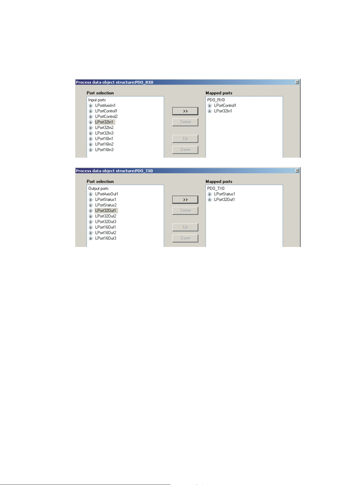
3. Click the Edit PDO button.
The selection window for editing the process data object is opened:
Here you can map the individual ports from the Port selection to the receive PDO
"PDO_RX0" by clicking the >> button. The Up and Down buttons serve to shift the sequence
of the ports within the PDO.
Note!
Port mapping is no configuration which can be carried out online for the Servo Drive
9400. This always requires an update of the »Engineer« project and a subsequent
download of the application.
54 Lenze · E94AYCER communication module (PROFINET®) · Communication Manual · DMS 9.0 EN · 12/2013 · TD17
Page 55
8 Process data transfer
_ _ _ _ _ _ _ _ _ _ _ _ _ _ _ _ _ _ _ _ _ _ _ _ _ _ _ _ _ _ _ _ _ _ _ _ _ _ _ _ _ _ _ _ _ _ _ _ _ _ _ _ _ _ _ _ _ _ _ _ _ _ _ _
In the following example, the ports "LPortControl1" and "Lport32In1" have been mapped
into the receive PDO "PDO_RX0" and the ports "LPortStatus1" and "LPort32Out1" have been
mapped into the transmit PDO "PDO_TX0":
4. Now link the mapped ports to the application signals in the selected technology
application.
• Activate the »FB-Editor« via the multiplexer codes (from code C03000) if this has not
been done yet.
• If the »FB Editor« is activated, the multiplexer codes are no longer available. In this case,
you must carry out the interconnection directly in the »FB Editor«.
Lenze · E94AYCER communication module (PROFINET®) · Communication Manual · DMS 9.0 EN · 12/2013 · TD17 55
Page 56

9 Parameter data transfer
Acyclic channel
Read
Write
IO
controller
IO device
9.1 The acyclic channel (PROFIdrive profile)
_ _ _ _ _ _ _ _ _ _ _ _ _ _ _ _ _ _ _ _ _ _ _ _ _ _ _ _ _ _ _ _ _ _ _ _ _ _ _ _ _ _ _ _ _ _ _ _ _ _ _ _ _ _ _ _ _ _ _ _ _ _ _ _
9 Parameter data transfer
9.1 The acyclic channel (PROFIdrive profile)
An optional service extension is the acyclic parameter data transfer.
Cyclic and acyclic PROFINET services can be operated simultaneously in the network.
Properties
• Only one parameter request is processed at a time (no pipelining).
• No spontaneous messages are transferred.
• There are only acyclic parameter requests.
• Profile-specific parameters can be read independently of the IO device state.
9.1.1 Connection establishment of an IO Controller to an IO device
An IO controller can always be used to request parameters from an IO device if the IO device is in the
"Data_Exchange" state.
E94YCER010
[9-1] Data communication via the acyclic channel
56
Lenze · E94AYCER communication module (PROFINET®) · Communication Manual · DMS 9.0 EN · 12/2013 · TD17
Page 57

9 Parameter data transfer
Write.res
withdata (parameter request)
withdata (parameter response)
without data
without data
without data
without data
Read.req
Read.res (-)
Read.req
Read.res (+)Parameter response
Paramet
er request
Parameter request
Parameter
processing
Parameter response
IO controller
IO device
Write.req (DB47)
9.1 The acyclic channel (PROFIdrive profile)
_ _ _ _ _ _ _ _ _ _ _ _ _ _ _ _ _ _ _ _ _ _ _ _ _ _ _ _ _ _ _ _ _ _ _ _ _ _ _ _ _ _ _ _ _ _ _ _ _ _ _ _ _ _ _ _ _ _ _ _ _ _ _ _
9.1.2 Acyclic data transmission process
[9-2] Data communication via the acyclic channel
• A "Write.req" is used to transmit the data set (DB47) in the form of a parameter request to the
IO device.
• "Write.res" confirms the receipt of the message by the IO controller.
• The IO controller requests the response of the IO device with "Read.req".
• The IO device responds with a "Read.res (-)" if processing is not yet completed.
• After parameter processing, the parameter request is completed by transmitting the parameter
response in the form of a "Read.res (+)" to the IO controller.
E94YCER011
Lenze · E94AYCER communication module (PROFINET®) · Communication Manual · DMS 9.0 EN · 12/2013 · TD17 57
Page 58

9 Parameter data transfer
9.1 The acyclic channel (PROFIdrive profile)
_ _ _ _ _ _ _ _ _ _ _ _ _ _ _ _ _ _ _ _ _ _ _ _ _ _ _ _ _ _ _ _ _ _ _ _ _ _ _ _ _ _ _ _ _ _ _ _ _ _ _ _ _ _ _ _ _ _ _ _ _ _ _ _
9.1.3 Structure of the PROFINET data telegram
Dest
Addr
6 bytes 6 bytes 4 bytes 4 bytes 80 bytes 64 bytes 64 bytes 0 ... 240 bytes 4 bytes
[9-3] PROFINET data telegram
Scr
Addr
VLAN
Day
Type
0800H
RPC NDR Read/Write
Block
Data FSC
In the "Read/Write Block", the initiator specifies the access to data set "DB47". The data which are
written to this index or read by it contain a header and the parameter request or the parameter
response. The data read or the data to be written are contained in the "Data" field.
The following subchapters describe the parameter request and the parameter response in detail.
PROFINET specification
Here you will find detailed information on the PROFINET data telegram.
Assignment of the user data depending on the data type
Depending on the data type used, the user data are assigned as follows:
Data type Length User data assignment
Byte 1 Byte 2 Byte 3 Byte 4 Byte ...
String x bytes
U8 1 byte 00
U16 2 bytes
High byte Low byte
U32 4 bytes High word Low word
High byte Low byte High byte Low byte
58
Lenze · E94AYCER communication module (PROFINET®) · Communication Manual · DMS 9.0 EN · 12/2013 · TD17
Page 59

9 Parameter data transfer
9.2 Reading parameters from the drive
_ _ _ _ _ _ _ _ _ _ _ _ _ _ _ _ _ _ _ _ _ _ _ _ _ _ _ _ _ _ _ _ _ _ _ _ _ _ _ _ _ _ _ _ _ _ _ _ _ _ _ _ _ _ _ _ _ _ _ _ _ _ _ _
9.2 Reading parameters from the drive
Note!
• When a read request is processed, no parameter value is written to the IO device.
• In the case of a multi-parameter read request, parameter attribute, index, and
subindex are repeated "n" times, "n" being the number of parameters requested.
Request header
Byte 1 Byte 2 Byte 3 Byte 4
Request reference Request identification Axis Number of indices
Field Data type Values
Request reference U8 This value is specified by the IO controller.
Request identification U8 0x01: Request parameters for reading
Axis U8 0x00 or 0x01
Number of indices U8 0x"n" (n = number of parameters requested)
Parameter attribute
Byte 5 Byte 6
Attribute Number of subindices
Field Data type Values
Attribute U8 0x10: Value
Number of subindices U8 0x00 or 0x01
Index and subindex
Byte 7 Byte 8 Byte 9 Byte 10
Index Subindex
High byte Low byte High byte Low byte
Field Data type Values
Index U16 0x0001 ... 0xFFFF (1 ... 65535)
Subindex U16 0x0001 ... 0xFFFF (1 ... 65535)
Lenze · E94AYCER communication module (PROFINET®) · Communication Manual · DMS 9.0 EN · 12/2013 · TD17 59
Page 60

9 Parameter data transfer
9.2 Reading parameters from the drive
_ _ _ _ _ _ _ _ _ _ _ _ _ _ _ _ _ _ _ _ _ _ _ _ _ _ _ _ _ _ _ _ _ _ _ _ _ _ _ _ _ _ _ _ _ _ _ _ _ _ _ _ _ _ _ _ _ _ _ _ _ _ _ _
9.2.1 Response to a correctly executed read request
Note!
• Responses to read requests do not contain parameter attributes and indices/
subindices.
• When a multi-parameter read request is transmitted, the parameter format and the
parameter value are repeated "n" times, "n" being the number of parameters
requested.
Response header
Byte 1 Byte 2 Byte 3 Byte 4
Request reference
(mirrored)
Response identification Axis
(mirrored)
Number of indices
Field Data type Values
Request reference U8 Mirrored value of the parameter request
Response identification U8 0x01: Parameter has been read
Axis U8 0x00 or 0x01
Number of indices U8 0x"n" (n = number of parameters requested)
Parameter format
Byte 5 Byte 6
Format Number of values
Field Data type Values
Format U8 0x02: Integer8
0x03: Integer16
0x04: Integer32
0x05: Unsigned8
0x06: Unsigned16
0x07: Unsigned32
0x09: Visible string
0x0A: Octet string
0x40: Zero
0x41: Byte
0x42: Word
0x43: Double word
Number of values U8 • 0x01
• Number of requested subindices. (If there is more
than one subindex, only the parameter value is
repeated.)
• In the case of string codes, the number of characters
is entered here.
60
Lenze · E94AYCER communication module (PROFINET®) · Communication Manual · DMS 9.0 EN · 12/2013 · TD17
Page 61

9 Parameter data transfer
9.2 Reading parameters from the drive
_ _ _ _ _ _ _ _ _ _ _ _ _ _ _ _ _ _ _ _ _ _ _ _ _ _ _ _ _ _ _ _ _ _ _ _ _ _ _ _ _ _ _ _ _ _ _ _ _ _ _ _ _ _ _ _ _ _ _ _ _ _ _ _
Parameter value
Byte 7 Byte 8 Byte 9 Byte 10
Value
Field Data type Values
Value String Any
U8 0x00 .... 0xFF
U16 0x0000 .... 0xFFFF
U32 0x0000 0000 .... 0xFFFF FFFF
Lenze · E94AYCER communication module (PROFINET®) · Communication Manual · DMS 9.0 EN · 12/2013 · TD17 61
Page 62

9 Parameter data transfer
9.2 Reading parameters from the drive
_ _ _ _ _ _ _ _ _ _ _ _ _ _ _ _ _ _ _ _ _ _ _ _ _ _ _ _ _ _ _ _ _ _ _ _ _ _ _ _ _ _ _ _ _ _ _ _ _ _ _ _ _ _ _ _ _ _ _ _ _ _ _ _
9.2.2 Response to a read error
Response header
Byte 1 Byte 2 Byte 3 Byte 4
Request reference
(mirrored)
Field Data type Values
Request reference U8 Mirrored value of the parameter request
Response identification U8 0x81: Parameter has not been read
Axis U8 0x00 or 0x01
Number of indices U8 0x"n" (n = number of parameters requested)
Parameter format
Response identification Axis
(mirrored)
• The data in the bytes 7 + 8 must be interpreted as an
Number of indices
error code.
Byte 5 Byte 6
Format Number of values
Field Data type Values
Format U8 0x44: Error
Number of values U8 0x01: Error code without additional information
0x02: Error code with additional information
Error code
Byte 7 Byte 8 Byte 9 Byte 10
Error code Additional information (if available)
High byte Low byte High byte Low byte
Field Data type Values
Error code U16 0x0000 .... 0xFFFF
Additional information
(if available)
Error information (error)
U16
( 71)
62
Lenze · E94AYCER communication module (PROFINET®) · Communication Manual · DMS 9.0 EN · 12/2013 · TD17
Page 63

9 Parameter data transfer
9.2 Reading parameters from the drive
_ _ _ _ _ _ _ _ _ _ _ _ _ _ _ _ _ _ _ _ _ _ _ _ _ _ _ _ _ _ _ _ _ _ _ _ _ _ _ _ _ _ _ _ _ _ _ _ _ _ _ _ _ _ _ _ _ _ _ _ _ _ _ _
9.2.3 Telegram example: Read request
The heatsink temperature of the inverter is to be read.
• Code to be read: C00061
• Heatsink temperature: 43 °C
Parameter request
Byte 1 Byte 2 Byte 3 Byte 4
Request reference Request identification Axis Number of indices
0xXX 0x01 0x00 0x01
Request parameters for reading
Byte 5 Byte 6
Attribute Number of subindices
0x10 0x00
Value No subindex
Byte 7 Byte 8 Byte 9 Byte 10
Index Subindex
High byte Low byte High byte Low byte
0x5F 0xC2 0x00 0x00
Index = 24575 - code no. = 24575 - 61 = 24514 = 0x5F C2 No subindex
Lenze · E94AYCER communication module (PROFINET®) · Communication Manual · DMS 9.0 EN · 12/2013 · TD17 63
Page 64

9 Parameter data transfer
9.2 Reading parameters from the drive
_ _ _ _ _ _ _ _ _ _ _ _ _ _ _ _ _ _ _ _ _ _ _ _ _ _ _ _ _ _ _ _ _ _ _ _ _ _ _ _ _ _ _ _ _ _ _ _ _ _ _ _ _ _ _ _ _ _ _ _ _ _ _ _
Parameter response to a correctly executed read request
Byte 1 Byte 2 Byte 3 Byte 4
Request reference Request identification Axis Number of indices
0xXX 0x01 0x00 0x01
(mirrored) Parameter has been read (mirrored)
Byte 5 Byte 6
Format Number of values
0x43 0x01
Double word 1 value
Byte 7 Byte 8 Byte 9 Byte 10
Value
High word: high byte High word: low byte Low- word: high byte Low word: low byte
0x00 0x00 0x00 0x2B
Read value = 0x00 00 00 2B = 43 x 1 (internal factor) = 43 [°C]
Parameter response to a read error
Byte 1 Byte 2 Byte 3 Byte 4
Request reference Request identification Axis Number of indices
0xXX 0x01 0x00 0x01
(mirrored) Parameter has been read (mirrored)
Byte 5 Byte 6
Format Number of values
0x44 0x01
Error Error code without additional
Byte 7 Byte 8
Error code
High byte Low byte
For the meaning see the chapter "Error information
(error)" ( 71)
information
64
Lenze · E94AYCER communication module (PROFINET®) · Communication Manual · DMS 9.0 EN · 12/2013 · TD17
Page 65

9 Parameter data transfer
9.3 Writing parameters to the drive
_ _ _ _ _ _ _ _ _ _ _ _ _ _ _ _ _ _ _ _ _ _ _ _ _ _ _ _ _ _ _ _ _ _ _ _ _ _ _ _ _ _ _ _ _ _ _ _ _ _ _ _ _ _ _ _ _ _ _ _ _ _ _ _
9.3 Writing parameters to the drive
Note!
• When a multi-parameter write request is processed, the parameter attribute, index,
subindex, and then the parameter format and parameter value are repeated "n"
times, "n" being the number of parameters requested.
• A parameter request must not exceed the maximum data length of 238 bytes.
Request header
Byte 1 Byte 2 Byte 3 Byte 4
Request reference Request identification Axis Number of indices
Field Data type Values
Request reference U8 This value is specified by the IO controller.
Request identification U8 0x02: Write parameter
Axis U8 0x00 or 0x01
Number of indices U8 0x"n" (n = number of parameters requested)
Parameter attribute
Byte 5 Byte 6
Attribute Number of subindices
Field Data type Values
Attribute U8 0x10: Value
Number of subindices U8 0x00 or 0x01
Index and subindex
Byte 7 Byte 8 Byte 9 Byte 10
Index Subindex
High byte Low byte High byte Low byte
Field Data type Values
Index U16 0x0001 ... 0xFFFF (1 ... 65535)
Subindex U16 0x0001 ... 0xFFFF (1 ... 65535)
Lenze · E94AYCER communication module (PROFINET®) · Communication Manual · DMS 9.0 EN · 12/2013 · TD17 65
Page 66

9 Parameter data transfer
9.3 Writing parameters to the drive
_ _ _ _ _ _ _ _ _ _ _ _ _ _ _ _ _ _ _ _ _ _ _ _ _ _ _ _ _ _ _ _ _ _ _ _ _ _ _ _ _ _ _ _ _ _ _ _ _ _ _ _ _ _ _ _ _ _ _ _ _ _ _ _
Parameter format
Byte 11 Byte 12
Format Number of values
Field Data type Values
Format U8 0x02: Integer8
0x03: Integer16
0x04: Integer32
0x05: Unsigned8
0x06: Unsigned16
0x07: Unsigned32
0x09: Visible string
0x0A: Octet string
0x40: Zero
0x41: Byte
0x42: Word
0x43: Double word
Number of values U8 • 0x01
• Number of requested subindices. (If there is more
than one subindex, only the parameter value is
repeated.)
• In the case of string codes, the number of characters
is entered here.
Parameter value
Byte 13 Byte 14 Byte 15 Byte 16
Value
Field Data type Values
Value String Any
U8 0x00 .... 0xFF
U16 0x0000 .... 0xFFFF
U32 0x0000 0000 .... 0xFFFF FFFF
66
Lenze · E94AYCER communication module (PROFINET®) · Communication Manual · DMS 9.0 EN · 12/2013 · TD17
Page 67

9 Parameter data transfer
9.3 Writing parameters to the drive
_ _ _ _ _ _ _ _ _ _ _ _ _ _ _ _ _ _ _ _ _ _ _ _ _ _ _ _ _ _ _ _ _ _ _ _ _ _ _ _ _ _ _ _ _ _ _ _ _ _ _ _ _ _ _ _ _ _ _ _ _ _ _ _
9.3.1 Response to a correctly executed write request
Response header
Byte 1 Byte 2 Byte 3 Byte 4
Request reference
(mirrored)
Field Data type Values
Request reference U8 Mirrored value of the parameter request
Response identification U8 0x01: Parameter written
Axis U8 0x00 or 0x01
Number of indices U8 0x"n" (n = number of parameters requested)
9.3.2 Response to a write error
Response identification Axis
(mirrored)
Number of indices
Note!
In the case of a multi-parameter request, correct and possible faulty messages are
summarised in one telegram. They have the following data contents:
• Correct message
• Format: 0x40
• Number of values: 0x00
• Faulty message
• Format: 0x44
• Number of values: 0x01 or 0x02
• Error code without additional information (number of values = 0x01) or
• Error code with additional information (number of values = 0x02)
A faulty access to a parameter "n" is indicated at the nth position in the response
telegram of a multi-parameter request.
Lenze · E94AYCER communication module (PROFINET®) · Communication Manual · DMS 9.0 EN · 12/2013 · TD17 67
Page 68

9 Parameter data transfer
9.3 Writing parameters to the drive
_ _ _ _ _ _ _ _ _ _ _ _ _ _ _ _ _ _ _ _ _ _ _ _ _ _ _ _ _ _ _ _ _ _ _ _ _ _ _ _ _ _ _ _ _ _ _ _ _ _ _ _ _ _ _ _ _ _ _ _ _ _ _ _
Response header
Byte 1 Byte 2 Byte 3 Byte 4
Request reference
(mirrored)
Field Data type Values
Request reference U8 Mirrored value of the parameter request
Response identification U8 0x82: Parameter has not been written
Axis U8 0x00 or 0x01
Number of indices U8 0x"n" (n = number of parameters requested)
Parameter format
Byte 5 Byte 6
Format Number of values
Response identification Axis
(mirrored)
• The data in the bytes 7 + 8 must be interpreted as an
Number of indices
error code.
Field Data type Values
Format U8 0x44: Error
Number of values U8 0x01: Error code without additional information
0x02: Error code with additional information
Error code
Byte 7 Byte 8 Byte 9 Byte 10
Error code Additional information (if available)
High byte Low byte High byte Low byte
Field Data type Values
Error code U16 0x0000 .... 0xFFFF
Additional information
(if available)
Error information (error)
U16
( 71)
68
Lenze · E94AYCER communication module (PROFINET®) · Communication Manual · DMS 9.0 EN · 12/2013 · TD17
Page 69

9 Parameter data transfer
9.3 Writing parameters to the drive
_ _ _ _ _ _ _ _ _ _ _ _ _ _ _ _ _ _ _ _ _ _ _ _ _ _ _ _ _ _ _ _ _ _ _ _ _ _ _ _ _ _ _ _ _ _ _ _ _ _ _ _ _ _ _ _ _ _ _ _ _ _ _ _
9.3.3 Telegram example: Write request
In the inverter, the ramp time for quick stop is to be set to 50 ms.
Code to be written: C00105
Parameter request
Byte 1 Byte 2 Byte 3 Byte 4
Request reference Request identification Axis Number of indices
0xXX 0x02 0x00 0x01
Write parameters Axis 0 1 index
Byte 5 Byte 6
Attribute Number of subindices
0x10 0x00
Value No subindex
Byte 7 Byte 8 Byte 9 Byte 10
Index Subindex
High byte Low byte High byte Low byte
0x5F 0x96 0x00 0x00
Index = 24575 - code no. = 24575 - 105 = 24470 = 0x5F 96 No subindex
Byte 11 Byte 12
Format Number of values
0x43 0x01
Double word 1 value
Byte 13 Byte 14 Byte 15 Byte 16
Value
High word: high byte High word: low byte Low- word: high byte Low word: low byte
0x00 0x00 0x00 0x32
Value to be written = 0.05 [s] x 1000 (internal factor) = 50 = 0x00 00 00 32
Lenze · E94AYCER communication module (PROFINET®) · Communication Manual · DMS 9.0 EN · 12/2013 · TD17 69
Page 70

9 Parameter data transfer
9.3 Writing parameters to the drive
_ _ _ _ _ _ _ _ _ _ _ _ _ _ _ _ _ _ _ _ _ _ _ _ _ _ _ _ _ _ _ _ _ _ _ _ _ _ _ _ _ _ _ _ _ _ _ _ _ _ _ _ _ _ _ _ _ _ _ _ _ _ _ _
Parameter response to a correctly executed write request
Byte 1 Byte 2 Byte 3 Byte 4
Request reference Response identification Axis Number of indices
0xXX 0x02 0x00 0x01
(mirrored) Parameter has been written (mirrored) 1 index
Parameter response after write error
Byte 1 Byte 2 Byte 3 Byte 4
Request reference Response identification Axis Number of indices
0xXX 0x82 0x00 0x01
(mirrored) Parameter has not been written (mirrored) 1 index
Byte 5 Byte 6
Format Number of values
0x44 0x01
Error Error code without additional
information
Byte 7 Byte 8
Error code
High byte Low byte
For the meaning see the chapter "Error information
(error)" ( 71)
70
Lenze · E94AYCER communication module (PROFINET®) · Communication Manual · DMS 9.0 EN · 12/2013 · TD17
Page 71

9 Parameter data transfer
9.4 Error information (error)
_ _ _ _ _ _ _ _ _ _ _ _ _ _ _ _ _ _ _ _ _ _ _ _ _ _ _ _ _ _ _ _ _ _ _ _ _ _ _ _ _ _ _ _ _ _ _ _ _ _ _ _ _ _ _ _ _ _ _ _ _ _ _ _
9.4 Error information (error)
Error code Meaning Description Additional
0x0000 Impermissible parameter
number
0x0001 Parameter value cannot be
changed
0x0002 Lower or upper value limit
exceeded
0x0003 Faulty subindex Access to unavailable subindex Subindex
0x0004 No array Access with subindex to non-indicated parameter -
0x0005 Wrong data type Change access with value that does not match the
0x0006 No setting permitted (only
resettable)
0x0007 Description element cannot
be changed
0x0008 Reserved (PROFIdrive profile V2: PPO-Write requested in the IR
0x0009 Description data not
available
0x000A Reserved (PROFIdrive profile V2: Wrong access group) -
0x000B No parameter change rights Change access without parameter change rights -
0x000C Reserved (PROFIdrive profile V2: Wrong password) -
0x000D Reserved (PROFIdrive profile V2: Text in the cyclic traffic
0x000E Reserved (PROFIdrive profile V2: Name in the cyclic traffic
0x000F No text array available Access to unavailable text array (parameter value is
0x0010 Reserved (PROFIdrive profile V2: Missing PPO-Write) -
0x0011 Request cannot be executed
due to the operating state
0x0012 Reserved (PROFIdrive profile V2: Other error) -
0x0013 Reserved (PROFIdrive profile V2: date in the cyclic traffic
0x0014 Value impermissible Change access with the value that is inside the value
0x0015 Response too long The length of the current response exceeds the
0x0016 Parameter address
impermissible
0x0017 Format impermissible Write request: Impermissible or non-supported
0x0018 Number of values not
consistent
0x0019 Reserved - -
...
0x0064
Access to unavailable parameter -
Change access to a parameter value that cannot be
changed
Change access with value beyond the value limits Subindex
data type of the parameter
Change access with value unequal to 0 where this is
not permitted
Change access to a description element that cannot
be changed
is not available)
Access to unavailable description (parameter value is
available)
cannot be read)
cannot be read)
available)
Access is not possible due to temporary reasons not
specified here
cannot be read)
limits but not permissible for other permanent
reasons (parameters with defined individual values)
maximum transmittable length
Impermissible or non-supported value for attribute,
number of subindices, parameter number, or
subindex, or a combination
format of parameter data
Write request: Number of values of the parameter
data do not match the number of subindices in the
parameter address
information
Subindex
-
Subindex
Subindex
-
-
-
-
-
-
-
Subindex
-
-
-
-
Lenze · E94AYCER communication module (PROFINET®) · Communication Manual · DMS 9.0 EN · 12/2013 · TD17 71
Page 72

9 Parameter data transfer
9.4 Error information (error)
_ _ _ _ _ _ _ _ _ _ _ _ _ _ _ _ _ _ _ _ _ _ _ _ _ _ _ _ _ _ _ _ _ _ _ _ _ _ _ _ _ _ _ _ _ _ _ _ _ _ _ _ _ _ _ _ _ _ _ _ _ _ _ _
Error code Meaning Description Additional
0x0065 Manufacturer-specific - -
...
0x00FF
information
72
Lenze · E94AYCER communication module (PROFINET®) · Communication Manual · DMS 9.0 EN · 12/2013 · TD17
Page 73

9 Parameter data transfer
9.5 Consistent parameter data
_ _ _ _ _ _ _ _ _ _ _ _ _ _ _ _ _ _ _ _ _ _ _ _ _ _ _ _ _ _ _ _ _ _ _ _ _ _ _ _ _ _ _ _ _ _ _ _ _ _ _ _ _ _ _ _ _ _ _ _ _ _ _ _
9.5 Consistent parameter data
In the PROFINET communication system, data is permanently exchanged between the host
(CPU + IO Controller) and the Servo Drive 9400 via the plugged-on communication module. The IO
Controller and the CPU (central processing unit) of the host access a joint memory: The dual port
memory (DPM).
The DPM permits a data exchange in both directions (write/read):
Central processing unit
(CPU)
It could happen that a slower IO controller writing would be overtaken by a faster CPU reading
within a cycle time without any further data organisation.
In order to avoid such an impermissible state, the parameter data to be transmitted must be marked
as "consistent".
Data communication with consistent data
With consistency, either "reading" or "writing" is possible when the IO controller and the CPU
simultaneously access the memory:
• The IO controller transfers data only as a complete data set.
• The CPU can only access completely updated data sets.
• The IO controller cannot read or write data as long as the CPU accesses consistent data.
The result becomes clear from the example below:
CPU wants to read. IO controller wants to write at the same
Central processing unit
(CPU)
Dual port memory
(DPM)
Dual port memory
(DPM)
IO controller
time.
IO controller
1. As the IO controller can only write when the CPU is not reading, the IO controller has to wait
until the data are completely read by the CPU.
2. The IO controller only writes a complete data set into the DPM.
Configuring consistent data
Note!
Consistency is achieved by an appropriate Configuration of the IO Controller.
Information on the issue can be found in the documentation of your configuring
software.
Lenze · E94AYCER communication module (PROFINET®) · Communication Manual · DMS 9.0 EN · 12/2013 · TD17 73
Page 74

10 PROFIsafe
_ _ _ _ _ _ _ _ _ _ _ _ _ _ _ _ _ _ _ _ _ _ _ _ _ _ _ _ _ _ _ _ _ _ _ _ _ _ _ _ _ _ _ _ _ _ _ _ _ _ _ _ _ _ _ _ _ _ _ _ _ _ _ _
10 PROFIsafe
PROFINET enables the transfer of safe information via the PROFIsafe protocol in accordance with
the "PROFIsafe - Profile for Safety Technology" specification, version 2.0.
Note!
A safety bus system (PROFIsafe) can only be operated via the upper module slot (MXI1)
of the Servo Drive 9400.
• The PROFIsafe message is sent in the second slot of a PROFINET telegram.
• One bit of the PROFIsafe data is always used to control specific safety functions.
• The structure of the PROFIsafe data is described in the PROFIsafe profile.
• The length of the PROFIsafe data (also called PROFIsafe message) always is 8 bytes.
• The Servo Drive 9400 forwards the PROFIsafe message to the safety module for a safe
evaluation.
Documentation for the safety module SM301 (E94AYAE)
Here you can find detailed information on the PROFIsafe connection.
74 Lenze · E94AYCER communication module (PROFINET®) · Communication Manual · DMS 9.0 EN · 12/2013 · TD17
Page 75

11 Monitoring
11.1 Interruption of PROFINET communication
_ _ _ _ _ _ _ _ _ _ _ _ _ _ _ _ _ _ _ _ _ _ _ _ _ _ _ _ _ _ _ _ _ _ _ _ _ _ _ _ _ _ _ _ _ _ _ _ _ _ _ _ _ _ _ _ _ _ _ _ _ _ _ _
11 Monitoring
11.1 Interruption of PROFINET communication
An interruption of PROFINET communication in the "Data_Exchange" state, e.g. by cable break or
failure of the IO controller is recognised by the IO device.
The response to the communication interruption is controlled via the following settings:
1. During the initialisation of PROFINET communication, the watchdog monitoring time
specified in the IO controller (C13882
If the IO device does not receive any valid process data in the "Data_Exchange" state, the
process data are treated according to the setting in C13885
that were sent last by the IO controller can be used or set to zero.)
After the watchdog monitoring time has elapsed, the IO device changes to the
"No_Data_Exchange" state (C13861
status displays ( 79)).
There is no response in the IO device
/ C14882) is transferred to the IO device.
/ C14885. (Like this the data
/ C14861), and the red LED BE is activated (Fieldbus
.
2. To trigger a response in the IO device, the »Engineer« has to provide an additional Response
of the Servo Drive 9400 (C13880
In order to delay this response, you can set a monitoring time (C13881
• In the Lenze setting "0 ms" this monitoring is activated.
• With the setting "65535 ms" this monitoring is deactivated.
• A change in the monitoring mode becomes effective immediately.
• The monitoring time elapses when the "Data_Exchange" state is exited.
After this response delay has elapsed, the response set is executed with the error message
"PROFINET: "Data_Exchange" status quit [0x00c88131]
/ C14880) under the Monitoring tab.
/ C14881).
" ( 88).
Lenze · E94AYCER communication module (PROFINET®) · Communication Manual · DMS 9.0 EN · 12/2013 · TD17 75
Page 76

11 Monitoring
11.2 Interruption of internal communication
_ _ _ _ _ _ _ _ _ _ _ _ _ _ _ _ _ _ _ _ _ _ _ _ _ _ _ _ _ _ _ _ _ _ _ _ _ _ _ _ _ _ _ _ _ _ _ _ _ _ _ _ _ _ _ _ _ _ _ _ _ _ _ _
11.2 Interruption of internal communication
The response to a communication error between the communication module and the Servo Drive
9400 can be set via standard device codes C01501
MXI2).
(module in slot MXI1) and C01502 (module in slot
76
Lenze · E94AYCER communication module (PROFINET®) · Communication Manual · DMS 9.0 EN · 12/2013 · TD17
Page 77

12 Diagnostics
12.1 LED status displays
_ _ _ _ _ _ _ _ _ _ _ _ _ _ _ _ _ _ _ _ _ _ _ _ _ _ _ _ _ _ _ _ _ _ _ _ _ _ _ _ _ _ _ _ _ _ _ _ _ _ _ _ _ _ _ _ _ _ _ _ _ _ _ _
12 Diagnostics
For purposes of fault diagnostics, the communication module is provided with the LEDs on the front.
Furthermore you can carry out the Diagnosing with the »Engineer«
12.1 LED status displays
( 81).
Note!
During normal operation ...
• only the LEDs MS
• the green LEDs on the RJ45 sockets X241 and X242 must be lit or blinking
The following status displays are distinguished:
• Module status displays
( 78) and BS ( 79) should be lit permanently.
( 79).
( 78)
• Fieldbus status displays
• Status displays at X241 and X242
( 79)
( 80)
Lenze · E94AYCER communication module (PROFINET®) · Communication Manual · DMS 9.0 EN · 12/2013 · TD17 77
Page 78

12 Diagnostics
200 ms
200 ms
200 ms
200 ms
12.1 LED status displays
_ _ _ _ _ _ _ _ _ _ _ _ _ _ _ _ _ _ _ _ _ _ _ _ _ _ _ _ _ _ _ _ _ _ _ _ _ _ _ _ _ _ _ _ _ _ _ _ _ _ _ _ _ _ _ _ _ _ _ _ _ _ _ _
12.1.1 Module status displays
Module status displays are indicated by the LEDs MS, ME, and DE.
E94YCET001E
Pos. Colour Status Description
MS Green On
The communication module is supplied with voltage and is
connected to the standard device.
Blinking
The communication module is supplied with voltage, but is not
connected to the standard device. (Standard device is switched off,
in the initialisation phase, or not available.)
ME Red On
An error has occurred in the communication module.
Blinking
The "Node blinking test" PROFINET function is activated by the IO
controller.
The blinking LED serves to identify/localise accessible IO devices.
DE Red On
78
The communication module is not accepted by the basic device or
the basic device is not active (see notes in the documentation
relating to the basic device.)
Lenze · E94AYCER communication module (PROFINET®) · Communication Manual · DMS 9.0 EN · 12/2013 · TD17
Page 79

12 Diagnostics
200 ms
200 ms
200 ms
200 ms
12.1 LED status displays
_ _ _ _ _ _ _ _ _ _ _ _ _ _ _ _ _ _ _ _ _ _ _ _ _ _ _ _ _ _ _ _ _ _ _ _ _ _ _ _ _ _ _ _ _ _ _ _ _ _ _ _ _ _ _ _ _ _ _ _ _ _ _ _
12.1.2 Fieldbus status displays
Fieldbus status displays are indicated by the LEDs BS and BE.
LED Colour Status Description
BS Green Off The communication module is not active at the fieldbus.
Blinking
The communication module is in the "Data_Exchange" status.
BE Red On
Bus error/fault is active (e.g. Ethernet cable not connected). The
communication module is in the "No_Data_Exchange" state.
Blinking
Impermissible settings:
• Invalid station name
• Invalid IP parameters
The communication module has been initialised and continues to
work internally with the respective standard values.
E94YCET001E
Lenze · E94AYCER communication module (PROFINET®) · Communication Manual · DMS 9.0 EN · 12/2013 · TD17 79
Page 80

12 Diagnostics
50 ms
12.1 LED status displays
_ _ _ _ _ _ _ _ _ _ _ _ _ _ _ _ _ _ _ _ _ _ _ _ _ _ _ _ _ _ _ _ _ _ _ _ _ _ _ _ _ _ _ _ _ _ _ _ _ _ _ _ _ _ _ _ _ _ _ _ _ _ _ _
12.1.3 Status displays at X241 and X242
The LEDs at the RJ45 sockets X241 and X242 display the PROFINET connection status.
E94YCER001E
LED Colour Status Description
A Green On
A physical PROFINET connection is available.
B Yellow On or
flickers
Data are being exchanged via PROFINET.
80
Lenze · E94AYCER communication module (PROFINET®) · Communication Manual · DMS 9.0 EN · 12/2013 · TD17
Page 81
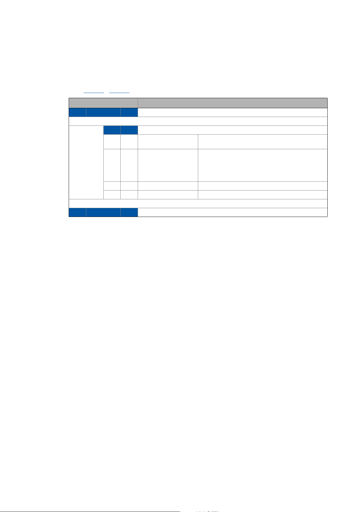
12 Diagnostics
12.2 Diagnosing with the »Engineer«
_ _ _ _ _ _ _ _ _ _ _ _ _ _ _ _ _ _ _ _ _ _ _ _ _ _ _ _ _ _ _ _ _ _ _ _ _ _ _ _ _ _ _ _ _ _ _ _ _ _ _ _ _ _ _ _ _ _ _ _ _ _ _ _
12.2 Diagnosing with the »Engineer«
Querying the current bus status
Code C13861
Assignment Meaning
Bit 0 ... Bit 3 Reserved
/ C14861 indicates the current PROFINET status in bit-coded form:
Bit 4 Bit 5 Status of the PROFINET state machine
0 0 Init After run-up, the IO device waits for a communication
partner and a system start-up.
0 1 Data_Exchange The "Data_Exchange" status has been reached:
If the parameter settings and the configuration have
been accepted by the firmware and by the application,
the IO device status changes to "Data_Exchange"
(exchange of user data with the IO controller).
1 0 - Undefined status
1 1 No_Data_Exchange The "Data_Exchange" status has been exited.
Bit 6 ... Bit 15 Reserved
Lenze · E94AYCER communication module (PROFINET®) · Communication Manual · DMS 9.0 EN · 12/2013 · TD17 81
Page 82

12 Diagnostics
12.3 Diagnostic data
_ _ _ _ _ _ _ _ _ _ _ _ _ _ _ _ _ _ _ _ _ _ _ _ _ _ _ _ _ _ _ _ _ _ _ _ _ _ _ _ _ _ _ _ _ _ _ _ _ _ _ _ _ _ _ _ _ _ _ _ _ _ _ _
12.3 Diagnostic data
• The IO device sends an alarm message to the IO controller to signalise the diagnostic data
below.
• Errors and warnings in the Servo Drive 9400 and the plugged-in modules are sent to the IO
controller as extended diagnostic messages.
• With code C13887
specific error messages.
• The diagnostic data are shown in code C13867
Bytes Information
0Slot
1
2Subslot
3
4 Error code
...
7
8Slot
9
10 Subslot
11
12 Error code
...
15
/ C14887 the transmission of an alarm message can be suppressed for
/ C14867:
Reference manual / »Engineer« online help for Servo Drive 9400
Here you will find detailed information on the error codes.
82
Lenze · E94AYCER communication module (PROFINET®) · Communication Manual · DMS 9.0 EN · 12/2013 · TD17
Page 83

13 Error messages
13.1 Short overview of the PROFINET error messages
_ _ _ _ _ _ _ _ _ _ _ _ _ _ _ _ _ _ _ _ _ _ _ _ _ _ _ _ _ _ _ _ _ _ _ _ _ _ _ _ _ _ _ _ _ _ _ _ _ _ _ _ _ _ _ _ _ _ _ _ _ _ _ _
13 Error messages
This chapter supplements the error list for the Servo Drive 9400 contained in the reference manual
and in the »Engineer« online help with the error messages of the communication module.
Reference manual / »Engineer« online help for Servo Drive 9400
Here you will find general information on diagnostics & fault analysis and on error
messages.
13.1 Short overview of the PROFINET error messages
The following table contains all error messages of the communication module in numerical order of
the error numbers. Moreover the preset error response and - if applicable - the parameters for
setting the error response are specified.
Tip!
If you click on the cross-reference in the first column, you will get a detailed description
(causes and remedies) of the corresponding error message.
Error number Designation Response (Lenze setting) Adjustable in
hex dec
0x00c85531
0x00c85532
0x00c85533
0x00c86010
0x00c86011
0x00c86100
0x00c86101
0x00c86110
0x00c8641f
0x00c86420
0x00c86430
0x00c86501
0x00c86502
0x00c86503
0x00c86532
0x00c86533
0x00c86610
0x00c86611
0x00c86612
0x00c86613
0x00c86650
0x00c88131
13129009 PROFINET: Memory: No access 6: Information -
13129010 PROFINET: Memory: Read error 6: Information -
13129011 PROFINET: Memory: Write error 6: Information -
13131792 PROFINET: Restart by watchdog reset 1: No Response -
13131793 PROFINET: Internal error 1: No Response -
13132032 PROFINET: Internal error 1: No Response -
13132033 PROFINET: Internal error 1: No Response -
13132048 PROFINET: Internal mapping error 4: Warning locked -
13132831 PROFINET: Invalid parameter set 1: No Response -
13132832 PROFINET: Error: Lenze setting loaded 1: No Response -
13132848 PROFINET: Invalid module configuration 6: Information -
13133057 PROFINET: Invalid READ.request during parameter access 4: Warning locked -
13133058 PROFINET: Invalid WRITE.request during parameter access 4: Warning locked -
13133059 PROFINET: Data output status bad 4: Warning locked -
13133106 PROFINET: Invalid station name 1: No Response -
13133107 PROFINET: Invalid IP parameters 1: No Response -
13133328 PROFINET: Safety communication timeout 4: Warning locked -
13133329 PROFINET: Safety parameter timeout 4: Warning locked -
13133330 PROFINET: Safety init error 4: Warning locked -
13133331 PROFINET: Safety connect error 5: Warning -
13133392 PROFINET: Internal error 6: Information -
13140273 PROFINET: "Data_Exchange" status quit 0: No Response C13880/1 /
C14880/1
Lenze · E94AYCER communication module (PROFINET®) · Communication Manual · DMS 9.0 EN · 12/2013 · TD17 83
Page 84

13 Error messages
13.2 Possible causes and remedies
_ _ _ _ _ _ _ _ _ _ _ _ _ _ _ _ _ _ _ _ _ _ _ _ _ _ _ _ _ _ _ _ _ _ _ _ _ _ _ _ _ _ _ _ _ _ _ _ _ _ _ _ _ _ _ _ _ _ _ _ _ _ _ _
13.2 Possible causes and remedies
In this chapter, all error messages of the communication module are listed in numerical order of the
error numbers. Possible causes and remedies and responses to the error messages are described in
detail.
PROFINET: Memory: No access [0x00c85531]
Response (Lenze setting printed in bold) Setting: not possible
None System fault Fault Trouble Quick stop by trouble Warning locked Warning Information
Cause Remedy
Access to memory was not possible. Download application again (including module)
If this happens repeatedly, send the communication
module together with a description of the fault to Lenze.
PROFINET: Memory: Read error [0x00c85532]
Response (Lenze setting printed in bold) Setting: not possible
None System fault Fault Trouble Quick stop by trouble Warning locked Warning Information
Cause Remedy
Parameter could not be read. Download application again (including module)
PROFINET: Memory: Write error [0x00c85533]
Response (Lenze setting printed in bold) Setting: not possible
None System fault Fault Trouble Quick stop by trouble Warning locked Warning Information
Cause Remedy
Parameter could not be written. Download application again (including module)
PROFINET: Restart by watchdog reset [0x00c86010]
Response (Lenze setting printed in bold) Setting: not possible
None System fault Fault Trouble Quick stop by trouble Warning locked Warning Information
Cause Remedy
Communication module is defective. Send communication module together with a
If this happens repeatedly, send the communication
module together with a description of the fault to Lenze.
If this happens repeatedly, send the communication
module together with a description of the fault to Lenze.
description of the fault to Lenze.
PROFINET: Internal error [0x00c86011]
Response (Lenze setting printed in bold) Setting: not possible
None System fault Fault Trouble Quick stop by trouble Warning locked Warning Information
Cause Remedy
Communication module is defective. Send communication module together with a
84
description of the fault to Lenze.
Lenze · E94AYCER communication module (PROFINET®) · Communication Manual · DMS 9.0 EN · 12/2013 · TD17
Page 85

13 Error messages
13.2 Possible causes and remedies
_ _ _ _ _ _ _ _ _ _ _ _ _ _ _ _ _ _ _ _ _ _ _ _ _ _ _ _ _ _ _ _ _ _ _ _ _ _ _ _ _ _ _ _ _ _ _ _ _ _ _ _ _ _ _ _ _ _ _ _ _ _ _ _
PROFINET: Internal error [0x00c86100]
Response (Lenze setting printed in bold) Setting: not possible
None System fault Fault Trouble Quick stop by trouble Warning locked Warning Information
Cause Remedy
Internal error Send communication module together with a
PROFINET: Internal error [0x00c86101]
Response (Lenze setting printed in bold) Setting: not possible
None System fault Fault Trouble Quick stop by trouble Warning locked Warning Information
Cause Remedy
Internal error Send communication module together with a
PROFINET: Internal mapping error [0x00c86110]
description of the fault to Lenze.
description of the fault to Lenze.
Response (Lenze setting printed in bold) Setting: not possible
None System fault Fault Trouble Quick stop by trouble Warning locked Warning Information
Cause Remedy
The selected PDO mapping is invalid:
• An object not supporting the required properties has
been specified.
• More than 64 bytes of data have been mapped.
PROFINET: Invalid parameter set [0x00c8641f]
Response (Lenze setting printed in bold) Setting: not possible
None System fault Fault Trouble Quick stop by trouble Warning locked Warning Information
Cause Remedy
No active parameter set could be loaded. Download application again (including module)
PROFINET: Error: Lenze setting loaded [0x00c86420]
Response (Lenze setting printed in bold) Setting: not possible
None System fault Fault Trouble Quick stop by trouble Warning locked Warning Information
Cause Remedy
Access to parameter set in memory module via standard
device was not successful.
Repeat PDO mapping
If this happens repeatedly, send the communication
module together with a description of the fault to Lenze.
Download application again (including module)
If this happens repeatedly, send the communication
module together with a description of the fault to Lenze.
( 53).
Lenze · E94AYCER communication module (PROFINET®) · Communication Manual · DMS 9.0 EN · 12/2013 · TD17 85
Page 86

13 Error messages
13.2 Possible causes and remedies
_ _ _ _ _ _ _ _ _ _ _ _ _ _ _ _ _ _ _ _ _ _ _ _ _ _ _ _ _ _ _ _ _ _ _ _ _ _ _ _ _ _ _ _ _ _ _ _ _ _ _ _ _ _ _ _ _ _ _ _ _ _ _ _
PROFINET: Invalid module configuration [0x00c86430]
Response (Lenze setting printed in bold) Setting: not possible
None System fault Fault Trouble Quick stop by trouble Warning locked Warning Information
Cause Remedy
A module or submodule does not comply with the
configuration of the Siemens »STEP7« project.
PROFINET: Invalid READ.request during parameter access [0x00c86501]
Response (Lenze setting printed in bold) Setting: not possible
None System fault Fault Trouble Quick stop by trouble Warning locked Warning Information
Cause Remedy
• During the parameter access to data set 47, the
controller has sent an invalid READ.request.
• When reading back the data, the IO Controller has
requested a data length (number of data bytes) that is
to small.
Check/correct configuration.
Check/correct configuration.
PROFINET: Invalid WRITE.request during parameter access [0x00c86502]
Response (Lenze setting printed in bold) Setting: not possible
None System fault Fault Trouble Quick stop by trouble Warning locked Warning Information
Cause Remedy
• During the parameter access to data set 47, the
PROFINET: Data output status bad [0x00c86503]
PROFINET: Invalid station name [0x00c86532]
controller has sent an invalid WRITE.request.
• When reading back the data, the IO Controller has
requested a data length (number of data bytes) that is
to small.
Response (Lenze setting printed in bold) Setting: not possible
None System fault Fault Trouble Quick stop by trouble Warning locked Warning Information
Cause Remedy
Output data invalid.
Connection to the Siemens Controller has been
interrupted.
Response (Lenze setting printed in bold) Setting: not possible
None System fault Fault Trouble Quick stop by trouble Warning locked Warning Information
Check/correct configuration.
• Check cables and terminals.
• Plug in the network cable on the PROFINET terminal
X241/X242.
86
Cause Remedy
Station name is not PROFINET-compliant. Use a PROFINET-compliant station name.
Setting the station name
Lenze · E94AYCER communication module (PROFINET®) · Communication Manual · DMS 9.0 EN · 12/2013 · TD17
( 35)
Page 87

13 Error messages
13.2 Possible causes and remedies
_ _ _ _ _ _ _ _ _ _ _ _ _ _ _ _ _ _ _ _ _ _ _ _ _ _ _ _ _ _ _ _ _ _ _ _ _ _ _ _ _ _ _ _ _ _ _ _ _ _ _ _ _ _ _ _ _ _ _ _ _ _ _ _
PROFINET: Invalid IP parameters [0x00c86533]
Response (Lenze setting printed in bold) Setting: not possible
None System fault Fault Trouble Quick stop by trouble Warning locked Warning Information
Cause Remedy
Incorrect IP parameters (IP address, subnet mask,
gateway address).
PROFINET: Safety communication timeout [0x00c86610]
Response (Lenze setting printed in bold) Setting: not possible
None System fault Fault Trouble Quick stop by trouble Warning locked Warning Information
Cause Remedy
Communication to the SM30x safety module is
disrupted.
PROFINET: Safety parameter timeout [0x00c86611]
Correct IP parameters.
Setting the IP configuration
Check if the SM30x safety module is plugged in and
supplied with voltage.
( 37)
Response (Lenze setting printed in bold) Setting: not possible
None System fault Fault Trouble Quick stop by trouble Warning locked Warning Information
Cause Remedy
The SM30x safety module does not respond to a
PROFISafe parameterisation telegram (PRM data) within
a given time interval (200 ms).
PROFINET: Safety init error [0x00c86612]
Response (Lenze setting printed in bold) Setting: not possible
None System fault Fault Trouble Quick stop by trouble Warning locked Warning Information
Cause Remedy
Communication to the SM30x safety module could not
be initialised correctly.
PROFINET: Safety connect error [0x00c86613]
Response (Lenze setting printed in bold) Setting: not possible
None System fault Fault Trouble Quick stop by trouble Warning locked Warning Information
Cause Remedy
Communication to the IO controller is disrupted. Check if the SM30x safety module is plugged in and
Check if the SM30x safety module is plugged in and
supplied with voltage.
Send communication module together with a
description of the fault to Lenze.
supplied with voltage.
PROFINET: Internal error [0x00c86650]
Response (Lenze setting printed in bold) Setting: not possible
None System fault Fault Trouble Quick stop by trouble Warning locked Warning Information
Cause Remedy
Internal error Send communication module together with a
Lenze · E94AYCER communication module (PROFINET®) · Communication Manual · DMS 9.0 EN · 12/2013 · TD17 87
description of the fault to Lenze.
Page 88

13 Error messages
13.2 Possible causes and remedies
_ _ _ _ _ _ _ _ _ _ _ _ _ _ _ _ _ _ _ _ _ _ _ _ _ _ _ _ _ _ _ _ _ _ _ _ _ _ _ _ _ _ _ _ _ _ _ _ _ _ _ _ _ _ _ _ _ _ _ _ _ _ _ _
PROFINET: "Data_Exchange" status quit [0x00c88131]
Response (Lenze setting printed in bold) Setting: C13880/1 / C14880/1 ( Configurable response)
None System fault Fault Trouble Quick stop by trouble Warning locked Warning Information
Cause Remedy
The data exchange via PROFINET has been terminated.
Also see the chapter "Interruption of PROFINET
communication" ( 75).
• Check cables and terminals.
• Plug in the network cable on the PROFINET terminal
X241/X242.
88
Lenze · E94AYCER communication module (PROFINET®) · Communication Manual · DMS 9.0 EN · 12/2013 · TD17
Page 89

14 Parameter reference
14.1 Parameters of the standard device that are relevant to communication
_ _ _ _ _ _ _ _ _ _ _ _ _ _ _ _ _ _ _ _ _ _ _ _ _ _ _ _ _ _ _ _ _ _ _ _ _ _ _ _ _ _ _ _ _ _ _ _ _ _ _ _ _ _ _ _ _ _ _ _ _ _ _ _
14 Parameter reference
This chapter supplements the parameter list and the table of attributes contained in the reference
manual and in the »Engineer« online help for the Servo Drive 9400 with the parameters of the
E94AYCER (PROFINET) communication module.
Reference manual/»Engineer« online help for Servo Drive 9400
Here you will find general information on parameters.
14.1 Parameters of the standard device that are relevant to communication
In this chapter communication-relevant parameters of the Servo Drive 9400 are listed in
numerically ascending order.
C00615
C00636
Parameter | Name:
C00615 | Resp. to imp. device conf.
Response to impermissible device configuration
Selection list
1Fault
3 Quick stop by trouble
4 Warning Locked
6 Information
0 No response
Subcodes Lenze setting Info
C00615/1 0: No Response Reserved
C00615/2 1: No response Resp. to imp. module in MXI1
C00615/3 1: No response Resp. to imp. module in MXI2
C00615/4 0: No Response Reserved
C00615/5 0: No Response Reserved
Read access Write access CINH PLC-STOP No transfer
Parameter | Name:
C00636 | Resp. to new module in MXI1
Response for the case where a new module has been plugged into slot 1 of the standard device.
Selection list (Lenze setting printed in bold)
1Fault
6 Information
5 Warning
4 Warning Locked
3 Quick stop by trouble
0 No response
Read access Write access CINH PLC-STOP No transfer
Data type: UNSIGNED_32
Index: 23960 = 5D98
Data type: UNSIGNED_32
Index: 23939 = 5D83
Lenze · E94AYCER communication module (PROFINET®) · Communication Manual · DMS 9.0 EN · 12/2013 · TD17 89
Page 90

14 Parameter reference
14.1 Parameters of the standard device that are relevant to communication
_ _ _ _ _ _ _ _ _ _ _ _ _ _ _ _ _ _ _ _ _ _ _ _ _ _ _ _ _ _ _ _ _ _ _ _ _ _ _ _ _ _ _ _ _ _ _ _ _ _ _ _ _ _ _ _ _ _ _ _ _ _ _ _
C00637
C01501
Parameter | Name:
C00637 | Resp. to new module in MXI2
Response if a new module has been plugged into module slot 2 of the standard device.
Selection list (Lenze setting printed in bold)
1Fault
6 Information
5 Warning
4 Warning Locked
3 Quick stop by trouble
0 No response
Read access Write access CINH PLC-STOP No transfer
Parameter | Name:
C01501 | Resp. to comm. error with MXI1
Response to a communication error between an "intelligent" module in slot 1 and the standard device
Selection list (Lenze setting printed in bold)
0 No response
1Fault
3 Quick stop by trouble
4 Warning Locked
5 Warning
Read access Write access CINH PLC-STOP No transfer
Data type: UNSIGNED_32
Index: 23939 = 5D83
Data type: UNSIGNED_32
Index: 23074 = 5A22
C01502
Parameter | Name:
C01502 | Resp. to comm. error with MXI2
Response to a communication error between an "intelligent" module in slot 2 and the standard device
Selection list (Lenze setting printed in bold)
0 No response
1Fault
3 Quick stop by trouble
4 Warning Locked
5 Warning
Read access Write access CINH PLC-STOP No transfer
Data type: UNSIGNED_32
Index: 23074 = 5A22
90
Lenze · E94AYCER communication module (PROFINET®) · Communication Manual · DMS 9.0 EN · 12/2013 · TD17
Page 91

14 Parameter reference
14.2 Parameters of the communication module for slot MXI1
_ _ _ _ _ _ _ _ _ _ _ _ _ _ _ _ _ _ _ _ _ _ _ _ _ _ _ _ _ _ _ _ _ _ _ _ _ _ _ _ _ _ _ _ _ _ _ _ _ _ _ _ _ _ _ _ _ _ _ _ _ _ _ _
14.2 Parameters of the communication module for slot MXI1
This chapter lists the parameters of the E94AYCER communication module (PROFINET) for slot MXI2
of the Servo Drive 9400 in numerically ascending order.
Note!
PROFINET command "Reset to Factory Defaults"
If the "Reset to factory defaults" PROFINET command is executed by an IO supervisor or
an IO controller, only the following PROFINET-related parameters of the communication
module will be reset to standard values:
• C13000
• C13001
• C13002
• C13010
• C13011
• C13012
• C13864
• C13899
• C13910
• C13911
• C13912
• C13913
• C13914
| IP address
| Subnetwork mask
| Gateway address
| Active IP address
| Active subnetwork mask
| Active gateway address
| Active station name
| Station name
| I&M1 system designation
| I&M1 installation site
| I&M2 installation date
| I&M3 additional information
| I&M4 signature code
C13000
C13001
Parameter | Name:
C13000 | IP address
Setting of the IP address
Setting the IP configuration
Setting range (min. value | unit | max. value) Lenze setting
0 4294967295 0
Read access Write access CINH PLC-STOP No transfer PDO_MAP_RX PDO_MAP_TX COM MOT
Parameter | Name:
C13001 | Subnetwork mask
Setting of the subnet mask
Setting the IP configuration
Setting range (min. value | unit | max. value) Lenze setting
0 4294967295 0
Read access Write access CINH PLC-STOP No transfer PDO_MAP_RX PDO_MAP_TX COM MOT
( 37)
( 37)
Data type: UNSIGNED_32
Data type: UNSIGNED_32
Index: 11575 = 0x2D37
Index: 11574 = 0x2D36
Lenze · E94AYCER communication module (PROFINET®) · Communication Manual · DMS 9.0 EN · 12/2013 · TD17 91
Page 92

14 Parameter reference
14.2 Parameters of the communication module for slot MXI1
_ _ _ _ _ _ _ _ _ _ _ _ _ _ _ _ _ _ _ _ _ _ _ _ _ _ _ _ _ _ _ _ _ _ _ _ _ _ _ _ _ _ _ _ _ _ _ _ _ _ _ _ _ _ _ _ _ _ _ _ _ _ _ _
C13002
C13003
C13010
Parameter | Name:
Data type: UNSIGNED_32
C13002 | Gateway address
Setting of the gateway address
Setting the IP configuration
( 37)
Setting range (min. value | unit | max. value) Lenze setting
0 4294967295 0
Read access Write access CINH PLC-STOP No transfer PDO_MAP_RX PDO_MAP_TX COM MOT
Parameter | Name:
Data type: OCTET_STRING
C13003 | MAC ID
Display of the MAC-ID
Read access Write access CINH PLC-STOP No transfer PDO_MAP_RX PDO_MAP_TX COM MOT
Parameter | Name:
Data type: UNSIGNED_8
C13010 | Active IP address
Display of the active IP address
The active IP address may differ from the contents of code C13000
changed via the fieldbus or the parameter(C13899
).
, depending on whether the station name was
Display range (min. value | unit | max. value)
0 255
Subcodes Info
C13010/1 Active IP address.1
C13010/2 Active IP address.2
C13010/3 Active IP address.3
C13010/4 Active IP address.4
Read access Write access CINH PLC-STOP No transfer PDO_MAP_RX PDO_MAP_TX COM MOT
Index: 11573 = 0x2D35
Index: 11572 = 0x2D34
Index: 11565 = 0x2D2D
C13011
92
Parameter | Name:
Data type: UNSIGNED_8
C13011 | Active subnetwork mask
Display of the active subnetwork mask
The active subnet mask may differ from the contents of code C13001
changed via the fieldbus or the parameter (C13899
).
, depending on whether the station name was
Display range (min. value | unit | max. value)
0 255
Subcodes Info
C13011/1 Active subnetwork mask.1
C13011/2 Active subnetwork mask.2
C13011/3 Active subnetwork mask.3
C13011/4 Active subnetwork mask.4
Read access Write access CINH PLC-STOP No transfer PDO_MAP_RX PDO_MAP_TX COM MOT
Lenze · E94AYCER communication module (PROFINET®) · Communication Manual · DMS 9.0 EN · 12/2013 · TD17
Index: 11564 = 0x2D2C
Page 93

14 Parameter reference
14.2 Parameters of the communication module for slot MXI1
_ _ _ _ _ _ _ _ _ _ _ _ _ _ _ _ _ _ _ _ _ _ _ _ _ _ _ _ _ _ _ _ _ _ _ _ _ _ _ _ _ _ _ _ _ _ _ _ _ _ _ _ _ _ _ _ _ _ _ _ _ _ _ _
C13012
C13850
Parameter | Name:
C13012 | Active gateway address
Display of the active gateway address
The active gateway address may differ from the contents of code C13002
was changed via the fieldbus or the parameter (C13899
Display range (min. value | unit | max. value)
0 255
Subcodes Info
C13012/1 Active gateway address.1
C13012/2 Active gateway address.2
C13012/3 Active gateway address.3
C13012/4 Active gateway address.4
Read access Write access CINH PLC-STOP No transfer PDO_MAP_RX PDO_MAP_TX COM MOT
Parameter | Name:
C13850 | All words to master
Display of the process data words which are transmitted from the communication module to the IO controller.
In the subcodes 1 to 32, all process data words to the IO controller are displayed. However, only the configured
process data words are valid.
Display range (min. value | unit | max. value)
0 65535
Subcodes Info
C13850/1
...
C13850/32
Read access Write access CINH PLC-STOP No transfer PDO_MAP_RX PDO_MAP_TX COM MOT
).
, depending on whether the station name
Data type: UNSIGNED_8
Index: 11563 = 0x2D2B
Data type: UNSIGNED_16
Index: 10725 = 0x29E5
C13851
Parameter | Name:
C13851 | All words from master
Display of the process data words which are transmitted from the IO controller to the communication module.
In the subcodes 1 to 32, all process data words from the IO controller are displayed. However, only the configured
process data words are valid.
Display range (min. value | unit | max. value)
0 65535
Subcodes Info
C13851/1
...
C13851/32
Read access Write access CINH PLC-STOP No transfer PDO_MAP_RX PDO_MAP_TX COM MOT
Data type: UNSIGNED_16
Index: 10724 = 0x29E4
Lenze · E94AYCER communication module (PROFINET®) · Communication Manual · DMS 9.0 EN · 12/2013 · TD17 93
Page 94

14 Parameter reference
14.2 Parameters of the communication module for slot MXI1
_ _ _ _ _ _ _ _ _ _ _ _ _ _ _ _ _ _ _ _ _ _ _ _ _ _ _ _ _ _ _ _ _ _ _ _ _ _ _ _ _ _ _ _ _ _ _ _ _ _ _ _ _ _ _ _ _ _ _ _ _ _ _ _
C13852
C13853
Parameter | Name:
C13852 | All words to standard device
Display of the process data words 1 ... 32, which are transmitted from the communication module to the drive.
Display range (min. value | unit | max. value)
0 65535
Subcodes Info
C13852/1
...
C13852/32
Read access Write access CINH PLC-STOP No transfer PDO_MAP_RX PDO_MAP_TX COM MOT
Parameter | Name:
C13853 | All words from standard device
Display of the process data words 1 ... 32, which are transmitted from the drive to the communication module.
Display range (min. value | unit | max. value)
0 65535
Subcodes Info
C13853/1
...
C13853/32
Read access Write access CINH PLC-STOP No transfer PDO_MAP_RX PDO_MAP_TX COM MOT
Data type: UNSIGNED_16
Index: 10723 = 0x29E3
Data type: UNSIGNED_16
Index: 10722 = 0x29E2
C13861
Parameter | Name:
C13861 | Bus state
Bit-coded display of current bus status
Querying the current bus status
Value is bit-coded:
Bit 0 Reserved
... ...
Bit 3 Reserved
Bit 4 Bit 4
Bit 5 Bit 5
Bit 6 Reserved
... ...
Bit 15 Reserved
Read access Write access CINH PLC-STOP No transfer PDO_MAP_RX PDO_MAP_TX COM MOT
( 81)
Data type: UNSIGNED_16
Index: 10714 = 0x29DA
94
Lenze · E94AYCER communication module (PROFINET®) · Communication Manual · DMS 9.0 EN · 12/2013 · TD17
Page 95

14 Parameter reference
14.2 Parameters of the communication module for slot MXI1
_ _ _ _ _ _ _ _ _ _ _ _ _ _ _ _ _ _ _ _ _ _ _ _ _ _ _ _ _ _ _ _ _ _ _ _ _ _ _ _ _ _ _ _ _ _ _ _ _ _ _ _ _ _ _ _ _ _ _ _ _ _ _ _
C13864
C13865
Parameter | Name:
C13864 | Active station name
Display of the active station name used by the drive.
The active station name may differ from the contents of code C13899
changed via the fieldbus or the parameter (C13899
Setting the station name
Read access Write access CINH PLC-STOP No transfer PDO_MAP_RX PDO_MAP_TX COM MOT
Parameter | Name:
C13865 | Display: Last safety PRM data
Display of the F_parameters sent last.
• These data are only valid if PROFIsafe is activated.
• The coding of the F_parameters is described in the PROFIsafe profile V2.0.
Read access Write access CINH PLC-STOP No transfer PDO_MAP_RX PDO_MAP_TX COM MOT
Bytes Information
0Slot
1
2Subslot
3
4Recldx
5
6 Accepted length
...
9
10 F_parameter
...
24
( 35)
).
, depending on whether the station name was
Data type: VISIBLE_STRING
Data type: OCTET_STRING
Index: 10711 = 0x29D7
Index: 10710 = 0x29D6
Lenze · E94AYCER communication module (PROFINET®) · Communication Manual · DMS 9.0 EN · 12/2013 · TD17 95
Page 96

14 Parameter reference
14.2 Parameters of the communication module for slot MXI1
_ _ _ _ _ _ _ _ _ _ _ _ _ _ _ _ _ _ _ _ _ _ _ _ _ _ _ _ _ _ _ _ _ _ _ _ _ _ _ _ _ _ _ _ _ _ _ _ _ _ _ _ _ _ _ _ _ _ _ _ _ _ _ _
C13867
Parameter | Name:
C13867 | Display: Most recent diagnostic data
Display of diagnostic data sent by the drive most recently:
Diagnostic data
Read access Write access CINH PLC-STOP No transfer PDO_MAP_RX PDO_MAP_TX COM MOT
Bytes Information
0Slot
1
2Subslot
3
4 Error code
...
7
8Slot
9
10 Subslot
11
12 Error code
...
15
( 82)
Data type: OCTET_STRING
Index: 10708 = 0x29D4
C13879
Parameter | Name:
C13879 | Bus error
Display of the error currently detected on the fieldbus.
Display range (min. value | unit | max. value)
0 4294967295
Read access Write access CINH PLC-STOP No transfer PDO_MAP_RX PDO_MAP_TX COM MOT
Value Meaning
0no error
1not used
2not used
3out of mem
4 add provider or consumer failed
5miss (consumer)
6cmi timeout
7 alarm-open failed
8 alarm-send.cnf(-)
9 alarm-ack-send.cnf(-)
10 alarm-data too long
11 alarm.ind(err)
12 rpc-client call.cnf(-)
13 ar-abort.req
Data type: UNSIGNED_32
Index: 10696 = 0x29C8
96
Lenze · E94AYCER communication module (PROFINET®) · Communication Manual · DMS 9.0 EN · 12/2013 · TD17
Page 97

14 Parameter reference
14.2 Parameters of the communication module for slot MXI1
_ _ _ _ _ _ _ _ _ _ _ _ _ _ _ _ _ _ _ _ _ _ _ _ _ _ _ _ _ _ _ _ _ _ _ _ _ _ _ _ _ _ _ _ _ _ _ _ _ _ _ _ _ _ _ _ _ _ _ _ _ _ _ _
Value Meaning
14 re-run aborts existing
15 got release.ind
16 device passivated
17 device / AR removed
18 protocol violation
19 NARE error
20 RPC-Bind error
21 RPC-Connect error
22 RPC-Read error
23 RPC-Write error
24 RPC-Control error
25 forbidden pull or plug after check.rsp and before in-data.ind
26 AP removed
27 link "down"
28 could not register multicast-mac
29 not synchronized (cannot start companion-ar)
30 wrong topology (cannot start companion-ar)
31 dcp, station-name changed
32 dcp, reset to factory-settings
33 cannot start companion-AR because a 0x8ipp submodule in the first AR...
• has appl-ready-pending (erroneous parameterisation)
• is locked (no parameterisation)
• is wrong or pulled (no parameterisation)
34 no irdata record yet
35 ownership of physical device
C13880
Parameter | Name:
C13880 | Monitoring Reaction
The action set in subcode 1 is executed when the node detects that it is no longer in the "Data_Exchange" state.
• Please also observe the notes provided in code C13881
• A change in the monitoring response becomes immediately effective.
Interruption of PROFINET communication
Selection list
0 No response
1Fault
3 Quick stop by trouble
4 Warning Locked
6 Information
Subcodes Lenze setting Info
C13880/1 0: No Response
Read access Write access CINH PLC-STOP No transfer PDO_MAP_RX PDO_MAP_TX COM MOT
( 75)
.
Data type: UNSIGNED_8
Index: 10695 = 0x29C7
Lenze · E94AYCER communication module (PROFINET®) · Communication Manual · DMS 9.0 EN · 12/2013 · TD17 97
Page 98

14 Parameter reference
14.2 Parameters of the communication module for slot MXI1
_ _ _ _ _ _ _ _ _ _ _ _ _ _ _ _ _ _ _ _ _ _ _ _ _ _ _ _ _ _ _ _ _ _ _ _ _ _ _ _ _ _ _ _ _ _ _ _ _ _ _ _ _ _ _ _ _ _ _ _ _ _ _ _
C13881
C13885
C13887
Parameter | Name:
C13881 | Response time when exiting "Data_Exchange"
Data type: UNSIGNED_16
Index: 10694 = 0x29C6
If the "Data_Exchange" status is exited, the response parameterised in C13880 is activated after the time set here
has expired.
• A value of "65535" in this code deactivates the monitoring function.
• A change in the monitoring response becomes immediately effective.
Setting range (min. value | unit | max. value) Lenze setting
0 ms 65535 0ms
Read access Write access CINH PLC-STOP No transfer PDO_MAP_RX PDO_MAP_TX COM MOT
Parameter | Name:
C13885 | Clear process data
Data type: UNSIGNED_8
Index: 10690 = 0x29C2
This code is used to set the process data which the IO device is to process in order to maintain the internal
communication when the fieldbus has exited the "Data_Exchange" status.
Selection list (Lenze setting printed in bold)
0 Use of most recent master PDOs
1 PDOs are set to the value '0'
Read access Write access CINH PLC-STOP No transfer PDO_MAP_RX PDO_MAP_TX COM MOT
Parameter | Name:
C13887 | Suppression diagnostic message
Data type: BITFIELD_8
Index: 10688 = 0x29C0
This code serves to inhibit the transmission of alarm messages to the IO controller. By this, errors of a specific type
can be systematically suppressed. All errors are furthermore entered in the logbook.
Value is bit-coded:
Bit 0 Fault
Bit 1 Trouble
Bit 2 Quick stop by trouble
Bit 3 Warning Locked
Bit 4 Warning
Bit 5 Reserved
Bit 6 Reserved
Bit 7 Reserved
Read access Write access CINH PLC-STOP No transfer PDO_MAP_RX PDO_MAP_TX COM MOT
C13899
98
Parameter | Name:
C13899 | Station name
Data type: VISIBLE_STRING
Index: 10676 = 0x29B4
The station name must be assigned in accordance with the PROFINET specification. In the standard setting a deleted
name is displayed. The name is also deleted if the "Reset to factory defaults" command is executed by an IO
supervisor or an IO controller.
Setting the station name
Read access Write access CINH PLC-STOP No transfer PDO_MAP_RX PDO_MAP_TX COM MOT
( 35)
Lenze · E94AYCER communication module (PROFINET®) · Communication Manual · DMS 9.0 EN · 12/2013 · TD17
Page 99

14 Parameter reference
14.2 Parameters of the communication module for slot MXI1
_ _ _ _ _ _ _ _ _ _ _ _ _ _ _ _ _ _ _ _ _ _ _ _ _ _ _ _ _ _ _ _ _ _ _ _ _ _ _ _ _ _ _ _ _ _ _ _ _ _ _ _ _ _ _ _ _ _ _ _ _ _ _ _
C13900
C13901
C13902
C13910
Parameter | Name:
C13900 | Firmware Product Type
Data type: VISIBLE_STRING
Index: 10675 = 0x29B3
The code contains a string with a length of 8 characters. The identification code "E94AFCER" is displayed.
Read access Write access CINH PLC-STOP No transfer PDO_MAP_RX PDO_MAP_TX COM MOT
Parameter | Name:
C13901 | Firmware Compilation Date
Data type: VISIBLE_STRING
Index: 10674 = 0x29B2
The code contains a string with a length of 20 characters. The software creation date ("MMM DD YYYY") and time
("hh:mm:ss") are displayed (e.g. "Mar 21 2005 12:31:21").
Read access Write access CINH PLC-STOP No transfer PDO_MAP_RX PDO_MAP_TX COM MOT
Parameter | Name:
C13902 | Firmware Version
Data type: VISIBLE_STRING
Index: 10673 = 0x29B1
The code contains a string with a length of 8 characters. The identification code is displayed (e.g. "01.10.09").
Read access Write access CINH PLC-STOP No transfer PDO_MAP_RX PDO_MAP_TX COM MOT
Parameter | Name:
C13910 | I&M1 system designation
Data type: VISIBLE_STRING
Index: 10665 = 0x29A9
Input/output of the I&M1 plant identification code
The Lenze setting shows an empty string.
Read access Write access CINH PLC-STOP No transfer PDO_MAP_RX PDO_MAP_TX COM MOT
C13911
C13912
C13913
Parameter | Name:
Data type: VISIBLE_STRING
C13911 | I&M1 installation site
Input/output of the I&M1 location identification code
The Lenze setting shows an empty string.
Read access Write access CINH PLC-STOP No transfer PDO_MAP_RX PDO_MAP_TX COM MOT
Parameter | Name:
Data type: VISIBLE_STRING
C13912 | I&M2 installation date
Input/output of the I&M2 date of installation
The Lenze setting shows an empty string.
Read access Write access CINH PLC-STOP No transfer PDO_MAP_RX PDO_MAP_TX COM MOT
Parameter | Name:
Data type: VISIBLE_STRING
C13913 | I&M3 additional information
Input/output if the I&M3 additional information
The Lenze setting shows an empty string.
Read access Write access CINH PLC-STOP No transfer PDO_MAP_RX PDO_MAP_TX COM MOT
Index: 10664 = 0x29A8
Index: 10663 = 0x29A7
Index: 10662 = 0x29A6
Lenze · E94AYCER communication module (PROFINET®) · Communication Manual · DMS 9.0 EN · 12/2013 · TD17 99
Page 100

14 Parameter reference
14.2 Parameters of the communication module for slot MXI1
_ _ _ _ _ _ _ _ _ _ _ _ _ _ _ _ _ _ _ _ _ _ _ _ _ _ _ _ _ _ _ _ _ _ _ _ _ _ _ _ _ _ _ _ _ _ _ _ _ _ _ _ _ _ _ _ _ _ _ _ _ _ _ _
C13914
Parameter | Name:
C13914 | I&M4 signature code
Input/output of the I&M4 signature
The Lenze setting shows an empty string.
Read access Write access CINH PLC-STOP No transfer PDO_MAP_RX PDO_MAP_TX COM MOT
Data type: OCTET_STRING
Index: 10661 = 0x29A5
100
Lenze · E94AYCER communication module (PROFINET®) · Communication Manual · DMS 9.0 EN · 12/2013 · TD17
 Loading...