

Page 1
EDK94AYCEN
.BA^
L−force Communication
Montageanleitung
Mounting Instructions
Instructions de montage
Instrucciones para el montaje
Istruzioni per il montaggio
Ethernet
Ä.BA^ä
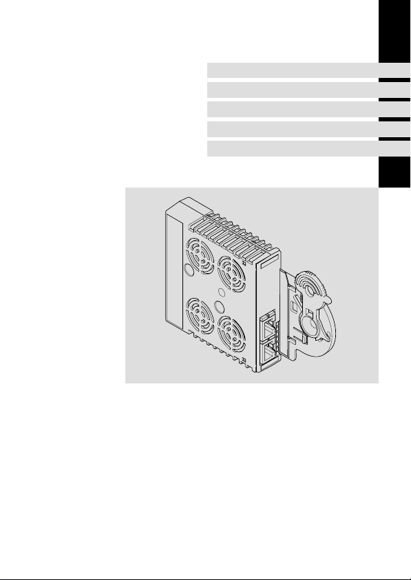
E94AYCEN
Kommunikationsmodul
Communication module
Module de communication
Módulo de comunicación
Modulo di comunicazione
Page 2

Lesen Sie zuerst diese Anleitung, bevor Sie mit den Arbeiten beginnen!
Beachten Sie die enthaltenen Sicherheitshinweise.
Please read these instructions before you start working!
Follow the enclosed safety instructions.
Veuillez lire attentivement cette documentation avant toute action !
Les consignes de sécurité doivent impérativement être respectées.
Lea las instrucciones antes de empezar a trabajar.
Observe las instrucciones de seguridad indicadas.
Prima di usare l’apparecchiatura, leggere le istruzioni contenute in questo
manuale.
Osservare le note di sicurezza.
Page 3
E94YCEN001A
E94AYCET017
Page 4
0Abb. 0Tab. 0
Lieferumfang
Pos. Beschreibung
Kommunikationsmodul E94AYCEN (Ethernet)
Montageanleitung
Anschlüsse
Pos. Beschreibung
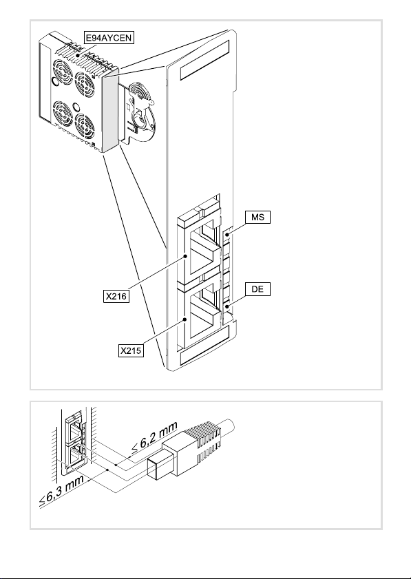
Ethernet−Anschlüsse
X215
Ausführung: jeweils RJ45−Buchse nach IEC 60603−7
X216
Statusanzeigen
LED
Pos. Farbe Zustand
MS grün an Das Kommunikationsmodul ist mit Spannung versorgt.
DE rot an Das Kommunikationsmodul wird vom Grundgerät nicht akzep-
LEDs am Anschluss X215/X216:
− gelb an / blinkt Daten werden über Ethernet ausgetauscht.
− grün an Ethernet−Verbindung ist vorhanden.
Beschreibung
tiert (siehe Hinweise in der Anleitung zum Grundgerät).
4
EDK94AYCEN DE/EN/FR/ES/IT 6.0
Page 5

Inhalt i
1 Über diese Dokumentation 6 . . . . . . . . . . . . . . . . . . . . . . . . . . . . . . . . . . . . . . . . . . . .
Verwendete Konventionen 7 . . . . . . . . . . . . . . . . . . . . . . . . . . . . . . . . . . . . . . . . . . . .
Verwendete Hinweise 8 . . . . . . . . . . . . . . . . . . . . . . . . . . . . . . . . . . . . . . . . . . . . . . . .
2 Sicherheitshinweise 10 . . . . . . . . . . . . . . . . . . . . . . . . . . . . . . . . . . . . . . . . . . . . . . . . . .
3 Produktbeschreibung 11 . . . . . . . . . . . . . . . . . . . . . . . . . . . . . . . . . . . . . . . . . . . . . . . .
Funktion 11 . . . . . . . . . . . . . . . . . . . . . . . . . . . . . . . . . . . . . . . . . . . . . . . . . . . . . . . . . . .
Bestimmungsgemäße Verwendung 11 . . . . . . . . . . . . . . . . . . . . . . . . . . . . . . . . . . . .
Identifikation 12 . . . . . . . . . . . . . . . . . . . . . . . . . . . . . . . . . . . . . . . . . . . . . . . . . . . . . . .
4 Mechanische Installation 13 . . . . . . . . . . . . . . . . . . . . . . . . . . . . . . . . . . . . . . . . . . . . .
5 Elektrische Installation 15 . . . . . . . . . . . . . . . . . . . . . . . . . . . . . . . . . . . . . . . . . . . . . . .
EMV−gerechte Verdrahtung 15 . . . . . . . . . . . . . . . . . . . . . . . . . . . . . . . . . . . . . . . . . . .
Ethernet−Anschluss 16 . . . . . . . . . . . . . . . . . . . . . . . . . . . . . . . . . . . . . . . . . . . . . . . . . .
Spannungsversorgung 19 . . . . . . . . . . . . . . . . . . . . . . . . . . . . . . . . . . . . . . . . . . . . . . .
EDK94AYCEN DE/EN/FR/ES/IT 6.0
5
Page 6

1 Über diese Dokumentation
1 Über diese Dokumentation
Inhalt
Diese Dokumentation enthält ...
ƒ Informationen zur mechanischen und elektrischen Installation des
Kommunikationsmoduls;
ƒ Sicherheitshinweise, die Sie unbedingt beachten müssen;
ƒ Angaben über Versionsstände der zu verwendenden Lenze Grundgeräte.
Informationen zur Gültigkeit
Die Informationen in dieser Dokumentation sind gültig für folgende Geräte:
Erweiterungsmodul Typenbezeichnung ab Hardwarestand ab Softwarestand
Kommunikationsmodul
Ethernet
Zielgruppe
Diese Dokumentation wendet sich an Personen, die das beschriebene Produkt nach Projektvorgabe installieren und in Betrieb nehmen.
E94AYCEN VC −
Tipp!
Dokumentationen und Software−Updates zu weiteren Lenze Produkten finden
Sie im Internet im Bereich "Services & Downloads" unter
http://www.Lenze.com
6
EDK94AYCEN DE/EN/FR/ES/IT 6.0
Page 7

Über diese Dokumentation
Verwendete Konventionen
Verwendete Konventionen
Diese Dokumentation verwendet folgende Konventionen zur Unterscheidung verschiedener Arten von Information:
Informationsart Auszeichnung Beispiele/Hinweise
Zahlenschreibweise
Dezimaltrennzeichen
Symbole
Seitenverweis
Punkt Es wird generell der Dezimalpunkt
verwendet.
Beispiel: 1234.56
Verweis auf eine andere Seite mit zusätzlichen Informationen
Beispiel: 16 = siehe Seite 16
1
EDK94AYCEN DE/EN/FR/ES/IT 6.0
7
Page 8

1 Über diese Dokumentation
Verwendete Hinweise
Verwendete Hinweise
Um auf Gefahren und wichtige Informationen hinzuweisen, werden in dieser Dokumentation folgende Piktogramme und Signalwörter verwendet:
Sicherheitshinweise
Aufbau der Sicherheitshinweise:
Gefahr!
(kennzeichnet die Art und die Schwere der Gefahr)
Hinweistext
(beschreibt die Gefahr und gibt Hinweise, wie sie vermieden werden kann)
Piktogramm und Signalwort Bedeutung
Gefahr von Personenschäden durch gefährliche elektrische Spannung
Gefahr!
Gefahr!
Stop!
Hinweis auf eine unmittelbar drohende Gefahr, die den
Tod oder schwere Verletzungen zur Folge haben kann,
wenn nicht die entsprechenden Maßnahmen getroffen
werden.
Gefahr von Personenschäden durch eine allgemeine Gefahrenquelle
Hinweis auf eine unmittelbar drohende Gefahr, die den
Tod oder schwere Verletzungen zur Folge haben kann,
wenn nicht die entsprechenden Maßnahmen getroffen
werden.
Gefahr von Sachschäden
Hinweis auf eine mögliche Gefahr, die Sachschäden zur
Folge haben kann, wenn nicht die entsprechenden Maßnahmen getroffen werden.
8
EDK94AYCEN DE/EN/FR/ES/IT 6.0
Page 9

Anwendungshinweise
Piktogramm und Signalwort Bedeutung
Über diese Dokumentation
Verwendete Hinweise
1
Hinweis!
Tipp!
Wichtiger Hinweis für die störungsfreie Funktion
Nützlicher Tipp für die einfache Handhabung
Verweis auf andere Dokumentation
EDK94AYCEN DE/EN/FR/ES/IT 6.0
9
Page 10

2 Sicherheitshinweise
2 Sicherheitshinweise
Gefahr!
Unsachgemäßer Umgang mit dem Kommunikationsmodul und dem
Grundgerät kann schwere Personenschäden und Sachschäden verursachen.
Beachten Sie die in der Dokumentation zum Grundgerät enthaltenen
Sicherheitshinweise und Restgefahren.
Stop!
Elektrostatische Entladung
Durch elektrostatische Entladung können elektronische Bauteile innerhalb des
Kommunikationsmoduls beschädigt oder zerstört werden.
Mögliche Folgen:
ƒ Das Kommunikationsmodul ist defekt.
ƒ Die Feldbus−Kommunikation ist nicht möglich oder fehlerhaft.
Schutzmaßnahmen
ƒ Befreien Sie sich vor dem Berühren des Moduls von elektrostatischen
Aufladungen.
10
EDK94AYCEN DE/EN/FR/ES/IT 6.0
Page 11

Produktbeschreibung
Funktion
3 Produktbeschreibung
Funktion
Das Kommunikationsmodul koppelt Lenze Servo Drives 9400 an das Kommunikationssystem Ethernet.
Bestimmungsgemäße Verwendung
Das Kommunikationsmodul ...
ƒ ist eine Zubehör−Baugruppe, die mit folgenden Lenze Grundgeräten eingesetzt
werden kann:
Produktreihe Typenbezeichnung ab Hardwarestand ab Softwarestand
Servo Drives 9400 E94AxxExxxx VB 01.50
ƒ ist ein Betriebsmittel zum Einsatz in industriellen Starkstromanlagen.
ƒ nur in Ethernet−Netzwerken einsetzen.
Jede andere Verwendung gilt als sachwidrig!
Tipp!
Weiterführende Informationen zu diesem Kommunikationsmodul finden Sie
im entsprechenden Kommunikationshandbuch.
Die PDF−Datei finden Sie im Internet im Bereich "Services & Downloads" unter
http://www.Lenze.com
3
EDK94AYCEN DE/EN/FR/ES/IT 6.0
11
Page 12
3 Produktbeschreibung
Identifikation
Identifikation
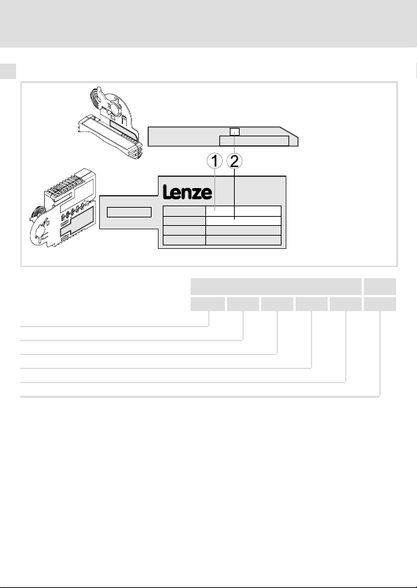
Type
HW Ver.
MAC ID
E94YCEN008
Typenschlüssel E94 A Y C EN Vx
Produktreihe
Gerätegeneration
Modulkennung: Erweiterungsmodul
Modultyp: Kommunikationsmodul
Ethernet
Hardwarestand
12
EDK94AYCEN DE/EN/FR/ES/IT 6.0
Page 13

Mechanische Installation 4
4 Mechanische Installation
Hinweis!
Ein Servo Drive 9400 darf nur mit einem Ethernet−Modul bestückt werden,
entweder in Modulschacht MXI1 oder MXI2.
Montage
EDK94AYCEN DE/EN/FR/ES/IT 6.0
E94YCXX001G
13
Page 14
4 Mechanische Installation
Demontage
E94AYCXX001H
14
EDK94AYCEN DE/EN/FR/ES/IT 6.0
Page 15
Elektrische Installation
EMV−gerechte Verdrahtung
5 Elektrische Installation
EMV−gerechte Verdrahtung
In typischen Anlagen ist die standardmäßige Schirmung der Ethernet−Kabel ausreichend.
In sehr stark gestörten Umgebungen kann eine Verbesserung der EMV−Festigkeit durch
eine zusätzliche Erdung des Kabelschirms ermöglicht werden.
Beachten Sie dazu folgende Hinweise:
1. Der Abstand der zusätzlichen Erdung vom Ethernet−Stecker ist abhängig vom
Steckplatz des Moduls. Der Abstand beträgt
– ca. 10 cm für den oberen Steckplatz (MXI1);
– ca. 20 cm für den unteren Steckplatz (MXI2).
2. Entfernen Sie ausgehend von diesem Abstand die Kunststoffumhüllung des Kabels
auf einer Länge von 2 cm.
3. Befestigen Sie den Kabelschirm am Schirmblech des Servo Drive 9400.
5
Befestigung am Schirmblech des Servo Drive 9400
Ethernet−Kabel an X216
Ethernet−Kabel an X215
Kommunikationsmodul in Steckplatz MXI1 des Servo Drive 9400
EDK94AYCEN DE/EN/FR/ES/IT 6.0
E94YCXX008
15
Page 16
5 Elektrische Installation
Ethernet−Anschluss
Ethernet−Anschluss
Zum Anschluss an das Kommunikationsmodul eignet sich ein handelsübliches Standard−
Ethernet−Patchkabel (siehe "Spezifikation des Ethernet−Kabels" (17)).
Hinweis!
ƒ Entkoppeln Sie Ihr Ethernet−Hausnetzwerk vom Betriebsnetzwerk für
Ethernet−fähige Lenze Geräte, um Störungen der Ethernet−Kommunikation
zu vermeiden.
Weiterführende Informationen dazu finden Sie im Handbuch "Ethernet in
der industriellen Anwendung".
ƒ Um Beschädigungen der RJ45−Buchse zu vermeiden, den Stecker des
Ethernet−Kabels senkrecht in die Buchse stecken bzw. aus der Buchse
ziehen.
Pinbelegung
RJ45−Buchse Pin Signal
E94AYCXX004C
1 Tx +
2 Tx −
3 Rx +
4 −
5 −
6 Rx−
7 −
8 −
Tipp!
Die Ethernet−Schnittstellen verfügen über eine Auto−MDIX−Funktion. Diese
Funktion passt die Polung der RJ45−Schnittstellen so an, dass unabhängig von
der Polung der gegenüberliegenden Ethernet−Schnittstelle und dem
verwendeten Kabeltyp (Standard−Patch−Kabel oder Cross−Over−Kabel) eine
Verbindung hergestellt wird.
16
EDK94AYCEN DE/EN/FR/ES/IT 6.0
Page 17

Elektrische Installation
Ethernet−Anschluss
Spezifikation des Ethernet−Kabels
Hinweis!
Verwenden Sie ausschließlich Kabel, die den aufgeführten Spezifikationen
entsprechen.
Spezifikation des Ethernet−Kabels
Ethernet−Standard Standard Ethernet (nach IEEE 802.3), 100Base−TX (Fast Ethernet)
Kabeltyp S/FTP (Screened Foiled Twisted Pair, ISO/IEC 11801 oder
Dämpfung 23.2 dB (bei 100 MHz und je 100 m)
Nebensprechdämpfung 24 dB (bei 100 MHz und je 100 m)
Rückflussdämpfung 10 dB (je 100 m)
Wellenwiderstand
EN 50173), CAT 5e
100 W
5
EDK94AYCEN DE/EN/FR/ES/IT 6.0
17
Page 18
5 Elektrische Installation
Ethernet−Anschluss
Farbcodierung des Ethernet−Kabels
Hinweis!
Die Verdrahtung und der Farbcode sind standardisiert in EIA/TIA 568A/568B.
Der Einsatz 4−poliger Ethernet−Kabel nach Industrienorm ist zulässig. Der
Kabeltyp verbindet nur die belegten Pins 1, 2, 3 und 6 miteinander.
Abb. 1 Ethernet−Stecker nach EIA/TIA 568A/568B
Paar Pin Signal EIA/TIA 568A EIA/TIA 568B
1
3
2 3 Rx + weiss / orange weiss / grün
1
2 6 Rx − orange grün
4
Tx + weiss / grün weiss / orange
2 Tx − grün orange
4 nicht belegt blau blau
5 nicht belegt weiss / blau blau / weiss
7 nicht belegt weiss / braun weiss / braun
8 nicht belegt braun braun
E94YCEI004A
18
EDK94AYCEN DE/EN/FR/ES/IT 6.0
Page 19

Elektrische Installation
Spannungsversorgung
Spannungsversorgung
Interne Versorgung
Das Kommunikationsmodul wird ausschließlich intern durch das Grundgerät mit Spannung versorgt.
Hinweis!
Bei Ausfall des Grundgerätes ist bei einer Linienverdrahtung der Datentransfer
zwischen den Ethernet−Teilnehmern an der Schnittstelle X215 und den
Ethernet−Teilnehmern an der Schnittstelle X216 unterbrochen.
5
EDK94AYCEN DE/EN/FR/ES/IT 6.0
19
Page 20

0Fig. 0Tab. 0
Scope of supply
Pos. Description
Communication module E94AYCEN (Ethernet)
Mounting Instructions
Connections
Pos. Description
Ethernet connections
X215
Design: RJ45 socket to IEC 60603−7
X216
Status displays
LED
Pos. Colour Condition
MS Green On The communication module is supplied with voltage.
DE Red On The communication module is not accepted by the standard
LEDs at connection X215/X216:
− Yellow On /
− Green On Ethernet connection is available.
blinking
Description
device (see notes given in the documentation for the standard
device).
Data is being exchanged via Ethernet.
20
EDK94AYCEN DE/EN/FR/ES/IT 6.0
Page 21

Contents i
1 About this documentation 22 . . . . . . . . . . . . . . . . . . . . . . . . . . . . . . . . . . . . . . . . . . . .
Conventions used 23 . . . . . . . . . . . . . . . . . . . . . . . . . . . . . . . . . . . . . . . . . . . . . . . . . . . .
Notes used 24 . . . . . . . . . . . . . . . . . . . . . . . . . . . . . . . . . . . . . . . . . . . . . . . . . . . . . . . . .
2 Safety instructions 26 . . . . . . . . . . . . . . . . . . . . . . . . . . . . . . . . . . . . . . . . . . . . . . . . . . .
3 Product description 27 . . . . . . . . . . . . . . . . . . . . . . . . . . . . . . . . . . . . . . . . . . . . . . . . . .
Function 27 . . . . . . . . . . . . . . . . . . . . . . . . . . . . . . . . . . . . . . . . . . . . . . . . . . . . . . . . . . .
Application as directed 27 . . . . . . . . . . . . . . . . . . . . . . . . . . . . . . . . . . . . . . . . . . . . . . .
Identification 28 . . . . . . . . . . . . . . . . . . . . . . . . . . . . . . . . . . . . . . . . . . . . . . . . . . . . . . .
4 Mechanical installation 29 . . . . . . . . . . . . . . . . . . . . . . . . . . . . . . . . . . . . . . . . . . . . . . .
5 Electrical installation 31 . . . . . . . . . . . . . . . . . . . . . . . . . . . . . . . . . . . . . . . . . . . . . . . . .
Wiring according to EMC 31 . . . . . . . . . . . . . . . . . . . . . . . . . . . . . . . . . . . . . . . . . . . . . .
Ethernet connection 32 . . . . . . . . . . . . . . . . . . . . . . . . . . . . . . . . . . . . . . . . . . . . . . . . .
Voltage supply 35 . . . . . . . . . . . . . . . . . . . . . . . . . . . . . . . . . . . . . . . . . . . . . . . . . . . . .
EDK94AYCEN DE/EN/FR/ES/IT 6.0
21
Page 22

1 About this documentation
1 About this documentation
Contents
This documentation contains ...
ƒ information about the mechanical and electrical installation of the communication
module;
ƒ safety instructions which must be followed;
ƒ specifications for the versions of the Lenze standard devices to be used.
Validity information
The information given in this documentation is valid for the following devices:
Extension module Type designation From hardware version From software version
Ethernet
communication
module
Target group
This documentation is intended for persons who install and commission the described
product according to the project requirements.
E94AYCEN VC −
Tip!
Documentation and software updates for further Lenze products can be found
on the Internet in the "Services & Downloads" area under
http://www.Lenze.com
22
EDK94AYCEN DE/EN/FR/ES/IT 6.0
Page 23

About this documentation
Conventions used
Conventions used
This documentation uses the following conventions to distinguish between different types
of information:
Type of information Identification Examples/notes
Numbers
Decimal separator
Symbols
Page reference
Point The decimal point is used throughout
this documentation.
Example: 1234.56
Reference to another page with
additional information
Example: 16 = see page 16
1
EDK94AYCEN DE/EN/FR/ES/IT 6.0
23
Page 24

1 About this documentation
Notes used
Notes used
The following pictographs and signal words are used in this documentation to indicate
dangers and important information:
Safety instructions
Structure of safety instructions:
Danger!
(characterises the type and severity of danger)
Note
(describes the danger and gives information about how to prevent dangerous
situations)
Pictograph and signal word Meaning
Danger of personal injury through dangerous electrical
Danger!
Danger!
Stop!
voltage.
Reference to an imminent danger that may result in
death or serious personal injury if the corresponding
measures are not taken.
Danger of personal injury through a general source of
danger.
Reference to an imminent danger that may result in
death or serious personal injury if the corresponding
measures are not taken.
Danger of property damage.
Reference to a possible danger that may result in
property damage if the corresponding measures are not
taken.
24
EDK94AYCEN DE/EN/FR/ES/IT 6.0
Page 25

Application notes
Pictograph and signal word Meaning
About this documentation
Notes used
1
Note!
Tip!
Important note to ensure troublefree operation
Useful tip for simple handling
Reference to another documentation
EDK94AYCEN DE/EN/FR/ES/IT 6.0
25
Page 26

2 Safety instructions
2 Safety instructions
Danger!
Inappropriate handling of the communication module and the standard device
can cause serious personal injury and material damage.
Observe the safety instructions and residual hazards described in the
documentation for the standard device.
Stop!
Electrostatic discharge
Electronic components of the communication module can be damaged or
destroyed through electrostatic discharge.
Possible consequences:
ƒ The communication module is damaged.
ƒ Fieldbus communication is not possible or faulty.
Protective measures
ƒ Discharge electrostatic charges before touching the module.
26
EDK94AYCEN DE/EN/FR/ES/IT 6.0
Page 27

Product description
Function
3 Product description
Function
The communication module connects Lenze Servo Drives 9400 with the Ethernet
communication system.
Application as directed
The communication module ...
ƒ is an accessory which can be used in conjunction with the following Lenze standard
devices:
Product series Type designation From hardware version From software version
Servo Drives 9400 E94AxxExxxx VB 01.50
ƒ is a device to be used in industrial power systems.
ƒ can only be used in Ethernet networks.
Any other use shall be deemed inappropriate!
Tip!
Further information about this communication module can be found in the
corresponding communication manual.
The pdf file can be found on the Internet in the "Services & Downloads" area
under
http://www.Lenze.com
3
EDK94AYCEN DE/EN/FR/ES/IT 6.0
27
Page 28

3 Product description
Identification
Identification
Type
HW Ver.
MAC ID
E94YCEN008
Type code E94 A Y C EN Vx
Product series
Device generation
Module identification: extension module
Module type: communication module
Ethernet
Hardware version
28
EDK94AYCEN DE/EN/FR/ES/IT 6.0
Page 29

Mechanical installation 4
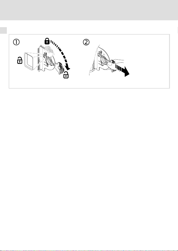
4 Mechanical installation
Note!
The Servo Drives 9400 must only be equipped with one Ethernet module,
either in module slot MXI1 or in module slot MXI2.
Mounting
EDK94AYCEN DE/EN/FR/ES/IT 6.0
E94YCXX001G
29
Page 30

4 Mechanical installation
Dismounting
E94AYCXX001H
30
EDK94AYCEN DE/EN/FR/ES/IT 6.0
Page 31

Electrical installation
Wiring according to EMC
5 Electrical installation
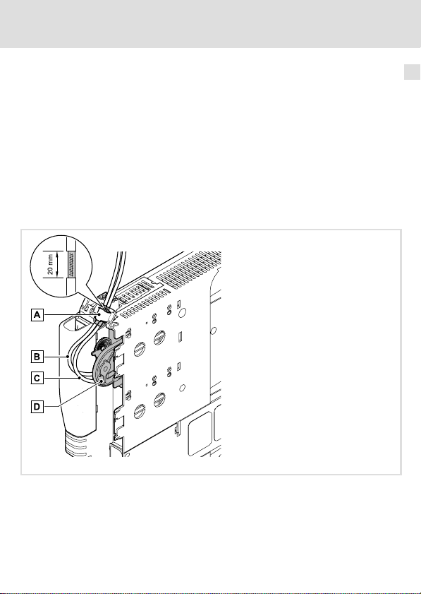
Wiring according to EMC
In typical systems, the standard Ethernet cable shielding is sufficient.
In environments that are subject to strong interferences, the electromagnetic compatibility
can be improved through an additional PE connection of the cable shield.
Please observe the following notes:
1. The distance between the additional PE connection and the Ethernet plug depends
on the module slot. It is
– approx. 10 cm for the upper slot (MXI1);
– approx. 20 cm for the lower slot (MXI2);
2. Consider this distance and remove the plastic sheath of the cable at a length of 2 cm.
3. Connect the cable shield to the shield sheet of the Servo Drive 9400.
5
Connection to the shield sheet of Servo Drive 9400
Ethernet cable at X216
Ethernet cable at X215
Communication module in slot MXI1 of Servo Drive 9400
EDK94AYCEN DE/EN/FR/ES/IT 6.0
E94YCXX008
31
Page 32

5 Electrical installation
Ethernet connection
Ethernet connection
You can use a standard Ethernet patch cable for connection to the communication module
(see "Ethernet cable specifications" (33)).
Note!
ƒ Isolate your Ethernet home network from the operating network for
Ethernet−capable Lenze devices to avoid Ethernet communication errors.
More information about this can be found in the Manual "Ethernet in
industrial applications".
ƒ Plug/remove the Ethernet cable plug vertically into/from the socket to
make sure that the RJ45 socket will not be damaged.
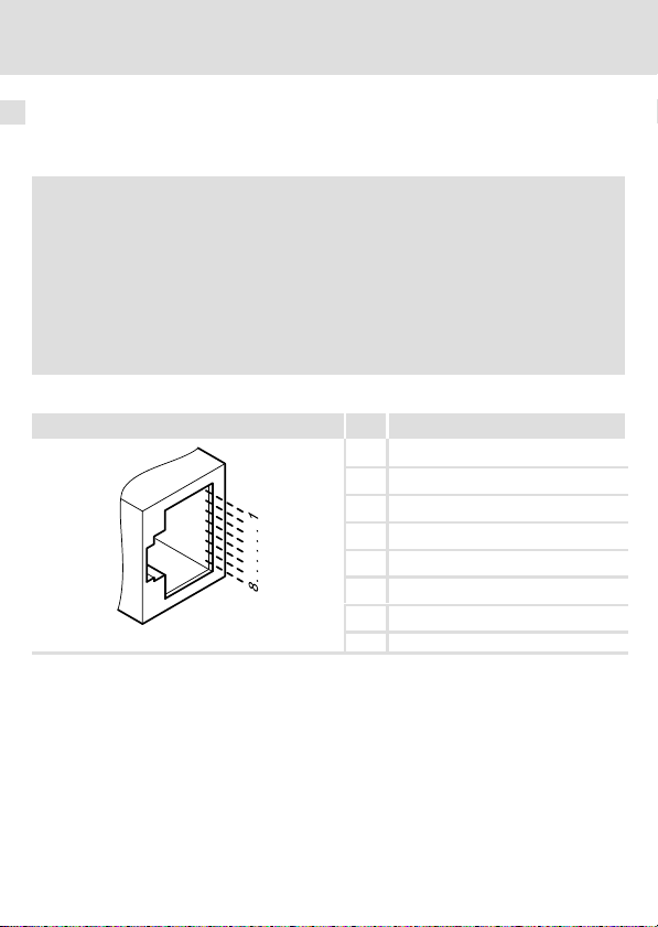
Pin assignment
RJ45 socket PIN Signal
E94AYCXX004C
1 Tx +
2 Tx −
3 Rx +
4 −
5 −
6 Rx −
7 −
8 −
Tip!
The Ethernet interfaces are equipped with an auto−MDIX function. This
function adapts the polarity of the RJ45 interfaces such that independently of
the polarity of the opposite Ethernet interface and the cable type used
(standard patch cable or crossover cable) a connection is established.
32
EDK94AYCEN DE/EN/FR/ES/IT 6.0
Page 33

Electrical installation
Ethernet connection
Ethernet cable specifications
Note!
Only use cables complying with the below specifications.
Specification of the Ethernet cable
Ethernet standard Standard Ethernet (in accordance with IEEE 802.3), 100Base−TX
Cable type S/FTP (Screened Foiled Twisted Pair, ISO/IEC 11801 or EN 50173),
Damping 23.2 dB (at 100 MHz and per 100 m)
Crosstalk damping 24 dB (at 100 MHz and per 100 m)
Return loss 10 dB (per 100 m)
Surge impedance
(Fast Ethernet)
CAT 5e
100 W
5
EDK94AYCEN DE/EN/FR/ES/IT 6.0
33
Page 34

5 Electrical installation
Ethernet connection
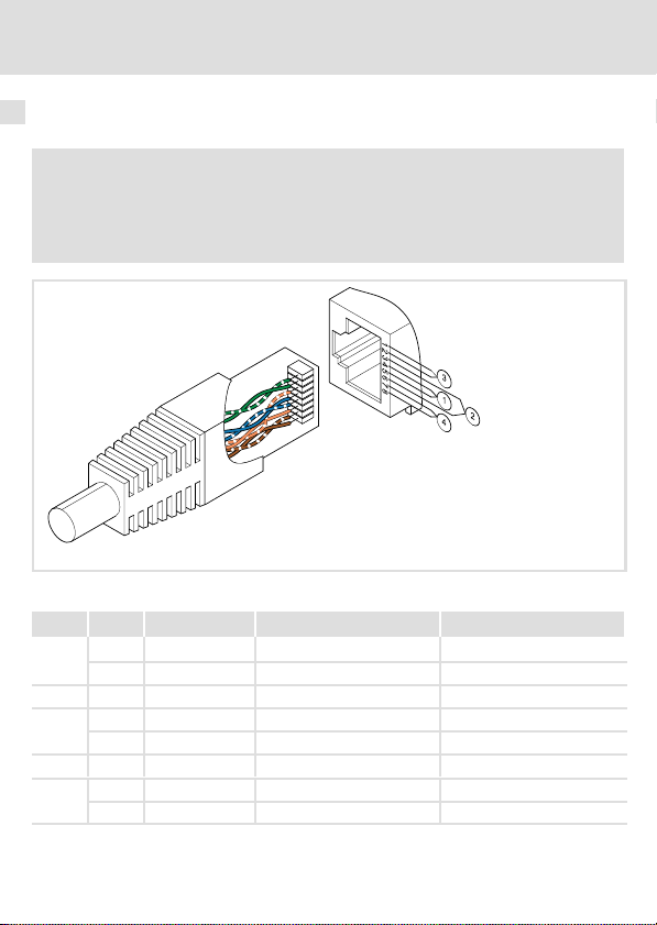
Colour code of Ethernet cable
Note!
Wiring and colour code are standardised in EIA/TIA 568A/568B.
You can use 4−pin Ethernet cables in accordance with the industrial standard.
The cable type only connects the assigned pins 1, 2, 3 and 6 with each other.
Fig. 1 Ethernet plug in accordance with EIA/TIA 568A/568B
Pair Pin Signal EIA/TIA 568A EIA/TIA 568B
1
3
2 3 Rx + White/orange White/green
1
2 6 Rx − Orange Green
4
Tx + White/green White/orange
2 Tx − Green Orange
4 Not assigned Blue Blue
5 Not assigned White/blue Blue/white
7 Not assigned White/brown White/brown
8 Not assigned Brown Brown
E94YCEI004A
34
EDK94AYCEN DE/EN/FR/ES/IT 6.0
Page 35

Electrical installation
Voltage supply
Voltage supply
Internal supply
The communication module is exclusively internally supplied with voltage by the standard
device.
Note!
With a line topology, data transfer between the Ethernet nodes at interface
X215 and the Ethernet nodes at interface X216 will be interrupted when the
standard device fails.
5
EDK94AYCEN DE/EN/FR/ES/IT 6.0
35
Page 36

0Fig. 0Tab. 0
Equipement livré
Pos. Description
Module de communication E94AYCEN (Ethernet)
Instructions de montage
Raccordements
Pos. Description
Raccordements Ethernet
X215
Configuration : une prise RJ45 selon CEI 60603−7 par raccordement
X216
Affichage d’état
LED
Pos. Couleur Etat
MS Vert ON Le module de communication est sous tension.
DE Rouge ON Le module de communication n’est pas reconnu par l’appareil de
LED au niveau du raccordement X215/X216 :
− Jaune ON/clignote Echange de données via Ethernet en cours
− Vert ON La liaison avec le réseau Ethernet est établie.
Description
base (voir instructions de mise en service de l’appareil de base).
36
EDK94AYCEN DE/EN/FR/ES/IT 6.0
Page 37

Sommaire i
1 Présentation du document 38 . . . . . . . . . . . . . . . . . . . . . . . . . . . . . . . . . . . . . . . . . . . .
Conventions utilisées 39 . . . . . . . . . . . . . . . . . . . . . . . . . . . . . . . . . . . . . . . . . . . . . . . . .
Consignes utilisées 40 . . . . . . . . . . . . . . . . . . . . . . . . . . . . . . . . . . . . . . . . . . . . . . . . . . .
2 Consignes de sécurité 42 . . . . . . . . . . . . . . . . . . . . . . . . . . . . . . . . . . . . . . . . . . . . . . . .
3 Description du produit 43 . . . . . . . . . . . . . . . . . . . . . . . . . . . . . . . . . . . . . . . . . . . . . . . .
Fonction 43 . . . . . . . . . . . . . . . . . . . . . . . . . . . . . . . . . . . . . . . . . . . . . . . . . . . . . . . . . . .
Utilisation conforme à la fonction 43 . . . . . . . . . . . . . . . . . . . . . . . . . . . . . . . . . . . . . .
Identification 44 . . . . . . . . . . . . . . . . . . . . . . . . . . . . . . . . . . . . . . . . . . . . . . . . . . . . . . .
4 Installation mécanique 45 . . . . . . . . . . . . . . . . . . . . . . . . . . . . . . . . . . . . . . . . . . . . . . .
5 Installation électrique 47 . . . . . . . . . . . . . . . . . . . . . . . . . . . . . . . . . . . . . . . . . . . . . . . .
Câblage conforme CEM 47 . . . . . . . . . . . . . . . . . . . . . . . . . . . . . . . . . . . . . . . . . . . . . . .
Raccordement Ethernet 48 . . . . . . . . . . . . . . . . . . . . . . . . . . . . . . . . . . . . . . . . . . . . . . .
Alimentation 51 . . . . . . . . . . . . . . . . . . . . . . . . . . . . . . . . . . . . . . . . . . . . . . . . . . . . . . .
EDK94AYCEN DE/EN/FR/ES/IT 6.0
37
Page 38

1 Présentation du document
1 Présentation du document
Contenu
Ce document contient ...
ƒ des informations sur l’installation mécanique et électrique du module de
communication ;
ƒ des consignes de sécurité qui doivent impérativement être respectées ;
ƒ des indications sur les versions des appareils de base Lenze à utiliser.
Informations relatives à la validité
Les informations contenues dans le présent document s’appliquent aux appareils suivants :
Module d’extension Référence de
Module de
communication
Ethernet
Public visé
Ce document est destiné aux personnes chargées d’installer et de mettre en service le
produit décrit selon les exigences du projet.
commande
E94AYCEN VC −
A partir de la version
matérielle
A partir de la version
logicielle
Conseil !
Les mises à jour de logiciels et les documentations relatives aux produits Lenze
sont disponibles dans la zone "Téléchargements" du site Internet :
http://www.Lenze.com
38
EDK94AYCEN DE/EN/FR/ES/IT 6.0
Page 39

Présentation du document
Conventions utilisées
Conventions utilisées
Pour faire la distinction entre différents types d’informations, ce document utilise les
conventions suivantes :
Type d’information Marquage Exemples/remarques
Représentation des chiffres
Séparateur décimal
Symboles
Renvoi à une page
Point Le point décimal est généralement
utilisé.
Exemple : 1234.56
Renvoi à une autre page présentant
des informations supplémentaires
Exemple : 16 = voir page 16
1
EDK94AYCEN DE/EN/FR/ES/IT 6.0
39
Page 40

1 Présentation du document
Consignes utilisées
Consignes utilisées
Pour indiquer des risques et des informations importantes, la présente documentation
utilise les mots et symboles suivants :
Consignes de sécurité
Présentation des consignes de sécurité
Danger !
(Le pictogramme indique le type de risque.)
Explication
(L’explication décrit le risque et les moyens de l’éviter.)
Pictogramme et mot associé Explication
Situation dangereuse pour les personnes en raison d’une
tension électrique élevée
Danger !
Danger !
Stop !
Indication d’un danger imminent qui peut avoir pour
conséquences des blessures mortelles ou très graves en
cas de non−respect des consignes de sécurité
correspondantes
Situation dangereuse pour les personnes en raison d’un
danger d’ordre général
Indication d’un danger imminent qui peut avoir pour
conséquences des blessures mortelles ou très graves en
cas de non−respect des consignes de sécurité
correspondantes
Risques de dégâts matériels
Indication d’un risque potentiel qui peut avoir pour
conséquences des dégâts matériels en cas de non−respect
des consignes de sécurité correspondantes
40
EDK94AYCEN DE/EN/FR/ES/IT 6.0
Page 41

Consignes d’utilisation
Pictogramme et mot associé Explication
Présentation du document
Consignes utilisées
1
Remarque
importante !
Conseil !
Remarque importante pour assurer un fonctionnement
correct
Conseil utile pour faciliter la mise en oeuvre
Référence à une autre documentation
EDK94AYCEN DE/EN/FR/ES/IT 6.0
41
Page 42

2 Consignes de sécurité
2 Consignes de sécurité
Danger !
Toute utilisation non conforme à la fonction du module de communication et
de l’appareil de base risque d’entraîner de sévères blessures et graves
dommages matériels.
Tenir compte des consignes de sécurité et des dangers résiduels indiqués dans
la documentation de l’appareil de base.
Stop !
Décharge électrostatique
Des composants électroniques à l’intérieur du module de communication
peuvent être endommagés ou détruits par des décharges électrostatiques.
Risques encourus :
ƒ Le module de communication est endommagé.
ƒ La communication par bus de terrain est impossible ou erronée.
Mesures de protection
ƒ Avant tout contact avec le module, se libérer des charges électrostatiques.
42
EDK94AYCEN DE/EN/FR/ES/IT 6.0
Page 43

Description du produit
Fonction
3 Description du produit
Fonction
Le module de communication relie les appareils Servo Drives 9400 de Lenze au système de
communication Ethernet.
Utilisation conforme à la fonction
Le module de communication ...
ƒ est un accessoire compatible avec les appareils de base Lenze suivants :
Série de produits Référence de
Servo Drives 9400 E94AxxExxxx VB 01.50
ƒ est un moyen de production à utiliser dans des installations à courant fort,
ƒ ne doit être utilisé que dans des réseaux Ethernet.
Toute autre utilisation est contre−indiquée !
commande
A partir de la version
matérielle
A partir de la version
logicielle
Conseil !
Pour plus d’informations sur ce module de communication, se reporter au
manuel de communication correspondant.
Le fichier PDF peut être téléchargé sur Internet sous "Services & Downloads" à
l’adresse suivante :
http://www.Lenze.com
3
EDK94AYCEN DE/EN/FR/ES/IT 6.0
43
Page 44

3 Description du produit
Identification
Identification
Type
HW Ver.
MAC ID
E94YCEN008
Codification des types E94 A Y C EN Vx
Série de produits
Génération d’appareils
Identification du module : module d’extension
Type de module : module de communication
Ethernet
Version matérielle
44
EDK94AYCEN DE/EN/FR/ES/IT 6.0
Page 45

Installation mécanique 4
4 Installation mécanique
Remarque importante !
Un variateur Servo Drive 9400 ne doit être équipé que d’un seul module
Ethernet (dans l’emplacement MXI1 ou MXI2).
Montage
EDK94AYCEN DE/EN/FR/ES/IT 6.0
E94YCXX001G
45
Page 46

4 Installation mécanique
Démontage
E94AYCXX001H
46
EDK94AYCEN DE/EN/FR/ES/IT 6.0
Page 47

Installation électrique
Câblage conforme CEM
5 Installation électrique
Câblage conforme CEM
Dans les installations types, un blindage standard du câble Ethernet suffit.
Dans les environnements soumis à de fortes perturbations, il est possible d’améliorer la
résistance CEM par une mise à la terre supplémentaire du blindage du câble.
Tenir compte des consignes suivantes :
1. L’écart entre la mise à la terre supplémentaire et le connecteur Ethernet dépend de
l’emplacement du module. Il est
– d’environ 10 cm pour l’emplacement du haut (MXI1) et
– d’environ 20 cm pour l’emplacement du bas (MXI2).
2. Compte tenu de l’écart indiqué ci−dessus, dénuder le câble sur environ 2 cm.
3. Fixer le blindage du câble à la tôle de blindage de l’appareil Servo Drive 9400.
5
Fixation à la tôle de blindage de l’appareil Servo Drive 9400
Câble Ethernet sur X216
Câble Ethernet sur X215
Module de communication dans l’emplacement MXI1 de l’appareil Servo Drive 9400
EDK94AYCEN DE/EN/FR/ES/IT 6.0
E94YCXX008
47
Page 48

5 Installation électrique
Raccordement Ethernet
Raccordement Ethernet
Le module de communication peut être raccordé à l’aide d’un câble droit Ethernet standard
en vente dans le commerce (voir "Spécifications du câble Ethernet" (49)).
Remarque importante !
ƒ Pour éviter tout problème de communication Ethernet, séparer le réseau
Ethernet du bâtiment de celui auquel les appareils Lenze compatibles avec
la technologie Ethernet doivent être raccordés.
Pour de plus amples informations à ce sujet, consulter le manuel
"L’Ethernet en application dans le milieu industriel".
ƒ Enficher ou retirer le connecteur du câble Ethernet verticalement afin
d’éviter tout endommagement de la prise RJ45.
Affectation des broches
Prise RJ45 BrocheSignal
E94AYCXX004C
1 Tx +
2 Tx −
3 Rx +
4 −
5 −
6 Rx −
7 −
8 −
Conseil !
Les interfaces Ethernet sont dotées d’une fonction Auto−MDIX. Celle−ci permet
d’adapter l’affectation des broches des prises RJ45 de manière à pouvoir établir
une liaison indépendamment de l’affectation des broches de l’autre interface
Ethernet raccordée et du type de câble utilisé (câble droit standard ou câble
croisé).
48
EDK94AYCEN DE/EN/FR/ES/IT 6.0
Page 49

Installation électrique
Raccordement Ethernet
Spécifications du câble Ethernet
Remarque importante !
Utiliser exclusivement des câbles conformes aux spécifications indiquées.
Spécifications du câble Ethernet
Standard Ethernet Standard Ethernet (selon IEEE 802.3), 100Base−TX (Fast Ethernet)
Type de câble S/FTP (Screened Foiled Twisted Pair, ISO/CEI 11801 ou EN 50173),
Amortissement 23.2 dB (pour 100 MHz et par segment de 100 m)
Affaiblissement diaphonique 24 dB (pour 100 MHz et par segment de 100 m)
Affaiblissement de régularité 10 dB (par segment de 100 m)
Impédance caractéristique
CAT 5e
100 W
5
EDK94AYCEN DE/EN/FR/ES/IT 6.0
49
Page 50

5 Installation électrique
Raccordement Ethernet
Codification des couleurs du câble Ethernet
Remarque importante !
Le câblage et la codification des couleurs sont définis par les normes EIA/TIA
568A/568B.
L’utilisation d’un câble Ethernet à 4 paires de fils conforme à la norme
industrielle est autorisée. Ce type de câble relie uniquement les broches
affectées 1, 2, 3 et 6.
Fig. 1 Connecteur Ethernet selon EIA/TIA 568A/568B
Paire Broche Signal EIA/TIA 568A EIA/TIA 568B
1
3
2 3 Rx + blanc/orange blanc/vert
1
2 6 Rx − orange vert
4
Tx + blanc/vert blanc/orange
2 Tx − vert orange
4 non affectée bleu bleu
5 non affectée blanc/bleu bleu/blanc
7 non affectée blanc/brun blanc/brun
8 non affectée brun brun
E94YCEI004A
50
EDK94AYCEN DE/EN/FR/ES/IT 6.0
Page 51

Installation électrique
Alimentation
Alimentation
Alimentation interne
Le module de communication est exclusivement alimenté en interne par l’appareil de base.
Remarque importante !
En cas de câblage en ligne, une panne de l’appareil de base provoque une
interruption du transfert de données entre les participants Ethernet raccordés
à l’interface X215 et ceux raccordés à l’interface X216.
5
EDK94AYCEN DE/EN/FR/ES/IT 6.0
51
Page 52

0Fig. 0Tab. 0
Oggetto della fornitura
Pos. Descrizione
Modulo di comunicazione E94AYCEN (Ethernet)
Istruzioni di montaggio
Collegamenti
Pos. Descrizione
Collegamenti Ethernet
X215
Esecuzione: connettore femmina RJ45 secondo IEC 60603−7
X216
Indicazioni di stato
LED
Pos. Colore Stato
MS verde acceso Il modulo di comunicazione riceve correttamente la tensione di
DE rosso acceso Il modulo di comunicazione non è accettato dal modulo asse
LED su collegamento X215/X216:
− giallo acceso /
− verde acceso Connessione Ethernet presente.
lampeggian
te
Descrizione
alimentazione.
(vedere le istruzioni al riguardo nel manuale del modulo asse).
Scambio di dati tramite Ethernet.
52
EDK94AYCEN DE/EN/FR/ES/IT 6.0
Page 53

Sommario i
1 Informazioni sul manuale 54 . . . . . . . . . . . . . . . . . . . . . . . . . . . . . . . . . . . . . . . . . . . . .
Convenzioni utilizzate 55 . . . . . . . . . . . . . . . . . . . . . . . . . . . . . . . . . . . . . . . . . . . . . . . .
Avvertenze utilizzate 56 . . . . . . . . . . . . . . . . . . . . . . . . . . . . . . . . . . . . . . . . . . . . . . . . .
2 Informazioni sulla sicurezza 57 . . . . . . . . . . . . . . . . . . . . . . . . . . . . . . . . . . . . . . . . . . .
3 Descrizione del prodotto 58 . . . . . . . . . . . . . . . . . . . . . . . . . . . . . . . . . . . . . . . . . . . . .
Funzione 58 . . . . . . . . . . . . . . . . . . . . . . . . . . . . . . . . . . . . . . . . . . . . . . . . . . . . . . . . . . .
Utilizzo conforme 58 . . . . . . . . . . . . . . . . . . . . . . . . . . . . . . . . . . . . . . . . . . . . . . . . . . . .
Identificazione 59 . . . . . . . . . . . . . . . . . . . . . . . . . . . . . . . . . . . . . . . . . . . . . . . . . . . . . .
4 Installazione meccanica 60 . . . . . . . . . . . . . . . . . . . . . . . . . . . . . . . . . . . . . . . . . . . . . . .
5 Installazione elettrica 62 . . . . . . . . . . . . . . . . . . . . . . . . . . . . . . . . . . . . . . . . . . . . . . . .
Cablaggio a norma EMC 62 . . . . . . . . . . . . . . . . . . . . . . . . . . . . . . . . . . . . . . . . . . . . . .
Collegamento Ethernet 63 . . . . . . . . . . . . . . . . . . . . . . . . . . . . . . . . . . . . . . . . . . . . . . .
Alimentazione 66 . . . . . . . . . . . . . . . . . . . . . . . . . . . . . . . . . . . . . . . . . . . . . . . . . . . . . .
EDK94AYCEN DE/EN/FR/ES/IT 6.0
53
Page 54

1 Informazioni sul manuale
1 Informazioni sul manuale
Contenuto
La presente documentazione contiene ...
ƒ informazioni sull’installazione meccanica ed elettrica del modulo di comunicazione;
ƒ informazioni sulla sicurezza da rispettare assolutamente;
ƒ informazioni sulle versioni dei dispositivi base Lenze da utilizzare.
Informazioni sulla validità
Le informazioni contenute nella presente documentazione sono valide per i seguenti
dispositivi:
Modulo di espansione Codice di
Modulo di
comunicazione
Ethernet
A chi è rivolta
La presente documentazione è rivolta al personale responsabile dell’installazione e della
messa in funzione come da progetto del prodotto descritto.
identificazione
E94AYCEN VC −
a partire dalla versione
hardware
a partire dalla versione
software
Suggerimento:
Per la documentazione e gli aggiornamenti software dei prodotti Lenze,
consultare in Internet la sezione "Services & Downloads" all’indirizzo
http://www.Lenze.com
54
EDK94AYCEN DE/EN/FR/ES/IT 6.0
Page 55

Informazioni sul manuale
Convenzioni utilizzate
Convenzioni utilizzate
La presente documentazione utilizza le seguenti convenzioni tipografiche per distinguere
i diversi tipi di informazioni:
Tipo di informazione Convenzione
Modalità di scrittura dei numeri
Separatore decimale
Simboli
Rimando a una pagina
tipografica
Punto Generalmente si utilizza il punto
Esempi/Note
decimale.
Esempio: 1234.56
Rimando a un’altra pagina con
informazioni aggiuntive
Esempio: 16 = si veda pagina 16
1
EDK94AYCEN DE/EN/FR/ES/IT 6.0
55
Page 56

1 Informazioni sul manuale
Avvertenze utilizzate
Avvertenze utilizzate
Per segnalare pericoli ed informazioni importanti, nella presente documentazione sono
riportati i seguenti simboli e parole di segnalazione:
Note di sicurezza
Struttura delle note di sicurezza:
Pericolo!
(indica il tipo e la gravità del pericolo)
Testo della nota
(descrive il pericolo e fornisce indicazioni su come può essere evitato)
Simbolo e parola di segnalazione Significato
Pericolo di danni alle persone dovuti a tensione elettrica
Pericolo!
Pericolo!
Stop!
Note di utilizzo
Simbolo e parola di segnalazione Significato
Avvertenza:
Segnala una situazione di pericolo che può provocare
morte o gravi lesioni se non vengono osservate le
necessarie misure precauzionali.
Pericolo di danni alle persone dovuti a una fonte generica
di pericolo
Segnala una situazione di pericolo che può provocare
morte o gravi lesioni se non vengono osservate le
necessarie misure precauzionali.
Pericolo di danni materiali
Segnala un possibile pericolo che può provocare danni
materiali se non vengono osservate le necessarie misure
precauzionali.
Avvertenza importante per assicurare un corretto
funzionamento dell’apparecchiatura
Suggerimento:
56
Utile suggerimento per un più semplice utilizzo
Rimando ad altra documentazione
EDK94AYCEN DE/EN/FR/ES/IT 6.0
Page 57

Informazioni sulla sicurezza 2
2 Informazioni sulla sicurezza
Pericolo!
Un utilizzo improprio del modulo di comunicazione e del dispositivo base può
causare gravi danni materiali e alle persone.
Rispettare le informazioni sulla sicurezza e sugli altri pericoli contenute nella
documentazione relativa al dispositivo base.
Stop!
Scariche elettrostatiche
Eventuali scariche elettrostatiche possono danneggiare o distruggere le
componenti elettroniche presenti all’interno del modulo di comunicazione.
Possibili conseguenze:
ƒ Malfunzionamento del modulo di comunicazione
ƒ Comunicazione con bus di campo impossibile o problematica.
Misure di protezione
ƒ Prima di toccare il modulo, dissipare le cariche elettrostatiche.
EDK94AYCEN DE/EN/FR/ES/IT 6.0
57
Page 58

3 Descrizione del prodotto
Funzione
3 Descrizione del prodotto
Funzione
Il modulo di comunicazione collega i Servo Drives 9400 Lenze al sistema di comunicazione
Ethernet.
Utilizzo conforme
Il modulo di comunicazione ...
ƒ è un modulo accessorio che può essere impiegato con i seguenti dispositivi base
Lenze:
Serie Codice di
Servo Drives 9400 E94AxxExxxx VB 01.50
ƒ è un mezzo di produzione da utilizzare negli impianti industriali ad alta tensione.
ƒ da utilizzare solo nelle reti Ethernet.
Ogni altro utilizzo è considerato indebito!
identificazione
a partire dalla versione
hardware
a partire dalla versione
software
Suggerimento:
Informazioni dettagliate su questo modulo di comunicazione sono disponibili
nel relativo manuale di comunicazione.
Il file PDF è disponibile in Internet, alla voce "Services & Downloads",
all’indirizzo
http://www.Lenze.com
58
EDK94AYCEN DE/EN/FR/ES/IT 6.0
Page 59

Descrizione del prodotto
Identificazione
Identificazione
Type
HW Ver.
MAC ID
E94YCEN008
Codice di identificazione E94 A Y C EN Vx
Serie
Versione dispositivo
Identificazione modulo: modulo di espansione
Tipo di modulo: modulo di comunicazione
Ethernet
Versione hardware
3
EDK94AYCEN DE/EN/FR/ES/IT 6.0
59
Page 60

4 Installazione meccanica
4 Installazione meccanica
Avvertenza:
Un Servo Drive 9400 può essere dotato di un solo modulo Ethernet, inserito
nello slot MXI1 o MXI2.
Montaggio
60
E94YCXX001G
EDK94AYCEN DE/EN/FR/ES/IT 6.0
Page 61

Smontaggio
Installazione meccanica 4
E94AYCXX001H
EDK94AYCEN DE/EN/FR/ES/IT 6.0
61
Page 62

5 Installazione elettrica
Cablaggio a norma EMC
5 Installazione elettrica
Cablaggio a norma EMC
Nei normali impianti è sufficiente una schermatura standard del cavo Ethernet.
In ambienti con forti interferenze, per migliorare l’immunità EMC è possibile realizzare un
ulteriore collegamento a terra della schermatura del cavo.
Per questo, osservare quanto segue:
1. La distanza del collegamento a terra aggiuntivo dal connettore Ethernet dipende
dallo slot in cui è inserito il modulo. La distanza è
– ca. 10 cm per lo slot superiore (MXI1);
– ca. 20 cm per lo slot inferiore (MXI2).
2. Partendo da questa distanza, rimuovere la guaina di plastica del cavo per una
lunghezza di 2 cm.
3. Fissare la schermatura sull’apposito supporto del Servo Drive 9400.
Fissaggio alla piastra di schermatura del Servo Drive 9400
Cavo Ethernet in X216
Cavo Ethernet in X215
Modulo di comunicazione nello slot MXI1 del Servo Drive 9400
62
E94YCXX008
EDK94AYCEN DE/EN/FR/ES/IT 6.0
Page 63

Installazione elettrica
Collegamento Ethernet
Collegamento Ethernet
Per il collegamento con il modulo di comunicazione è possibile utilizzare un cavo patch
Ethernet standard, reperibile in commercio (vedere "Specifiche del cavo Ethernet" (64)).
Avvertenza:
ƒ Disaccoppiare la rete Ethernet locale (LAN) dalla rete aziendale per
dispositivi Lenze abilitati per Ethernet, al fine di evitare interferenze nella
comunicazione Ethernet.
Per ulteriori informazioni al riguardo, consultare il manuale "Ethernet nelle
applicazioni industriali".
ƒ Per evitare danni alla presa RJ45, inserire il cavo Ethernet nella presa o
estrarlo da quest’ultima in verticale.
Assegnazione dei pin
Connettore femmina RJ45 Pin Segnale
1 Tx +
2 Tx −
3 Rx +
4 −
5 −
6 Rx −
7 −
E94AYCXX004C
8 −
5
Suggerimento:
Le interfacce Ethernet sono dotate di una funzione Auto−MDIX. Questa
funzione adatta la polarità delle interfacce RJ45 in modo da realizzare un
collegamento indipendentemente dalla polarità dell’interfaccia Ethernet
contrapposta e dal tipo di cavo utilizzato (cavo patch standard o cavo
cross−over).
EDK94AYCEN DE/EN/FR/ES/IT 6.0
63
Page 64

5 Installazione elettrica
Collegamento Ethernet
Specifiche del cavo Ethernet
Avvertenza:
Utilizzare esclusivamente cavi conformi alle specifiche.
Specifiche del cavo Ethernet
Standard Ethernet Ethernet standard (secondo IEEE 802.3), 100Base−TX (Fast
Tipo di cavo S/FTP (Screened Foiled Twisted Pair, ISO/IEC 11801 o EN 50173),
Attenuazione 23.2 dB (a 100 MHz e ogni 100 m)
Attenuazione di diafonia 24 dB (a 100 MHz e ogni 100 m)
Attenuazione del ritorno 10 dB (ogni 100 m)
Impedenza caratteristica
Ethernet)
CAT 5e
100 W
64
EDK94AYCEN DE/EN/FR/ES/IT 6.0
Page 65

Installazione elettrica
Collegamento Ethernet
Codifica dei colori del cavo Ethernet
Avvertenza:
Il cablaggio e la codifica dei colori sono conformi agli standard EIA/TIA
568A/568B.
È consentito l’impiego di cavi Ethernet a 4 poli secondo la normativa DIN. Il
tipo di cavo collega solo i pin assegnati 1, 2, 3 e 6 l’uno con l’altro.
Fig. 1 Connettore Ethernet secondo EIA/TIA 568A/568B
Coppia Pin Segnale EIA/TIA 568A EIA/TIA 568B
1
3
2 3 Rx + bianco / arancione bianco / verde
1
2 6 Rx − arancione verde
4
Tx + bianco / verde bianco / arancione
2 Tx − verde arancione
4 non assegnato blu blu
5 non assegnato bianco / azzurro azzurro / bianco
7 non assegnato bianco / marrone bianco / marrone
8 non assegnato marrone marrone
5
E94YCEI004A
EDK94AYCEN DE/EN/FR/ES/IT 6.0
65
Page 66

5 Installazione elettrica
Alimentazione
Alimentazione
Alimentazione interna
Il modulo di comunicazione viene alimentato soltanto internamente tramite il modulo
asse.
Avvertenza:
In caso di disattivazione del modulo asse con cablaggio di tipo lineare, il
trasferimento di dati tra i nodi Ethernet sull’interfaccia X215 e i nodi Ethernet
sull’interfaccia X216 viene interrotto.
66
EDK94AYCEN DE/EN/FR/ES/IT 6.0
Page 67

Installazione elettrica
Alimentazione
5
EDK94AYCEN DE/EN/FR/ES/IT 6.0
67
Page 68

0Fig. 0Tab. 0
Contenido del suministro
Pos. Descripción
Módulo de comunicación E94AYCEN (Ethernet)
Instrucciones de montaje
Conexiones
Pos. Descripción
Conexiones Ethernet
X215
Ejecución: conector RJ45 según IEC 60603−7
X216
Indicaciones de estado
LED
Pos. Color Estado
MS verde encendido El módulo de comunicación está siendo alimentado con voltaje.
DE rojo encendido El módulo de comunicación no es aceptado por el equipo básico
LEDs en el conector X215/X216:
− amarillo encendido /
− verde encendido Existe conexión de Ethernet.
parpadea
Descripción
(ver indicaciones en las instrucciones del equipo básico).
Los datos son intercambiados a través de Ethernet.
68
EDK94AYCEN DE/EN/FR/ES/IT 6.0
Page 69

Contenido i
1 Acerca de esta documentación 70 . . . . . . . . . . . . . . . . . . . . . . . . . . . . . . . . . . . . . . . . .
Convenciones utilizadas 71 . . . . . . . . . . . . . . . . . . . . . . . . . . . . . . . . . . . . . . . . . . . . . .
Indicaciones utilizadas 72 . . . . . . . . . . . . . . . . . . . . . . . . . . . . . . . . . . . . . . . . . . . . . . . .
2 Instrucciones de seguridad 73 . . . . . . . . . . . . . . . . . . . . . . . . . . . . . . . . . . . . . . . . . . . .
3 Descripción del producto 74 . . . . . . . . . . . . . . . . . . . . . . . . . . . . . . . . . . . . . . . . . . . . .
Función 74 . . . . . . . . . . . . . . . . . . . . . . . . . . . . . . . . . . . . . . . . . . . . . . . . . . . . . . . . . . . .
Uso previsto 74 . . . . . . . . . . . . . . . . . . . . . . . . . . . . . . . . . . . . . . . . . . . . . . . . . . . . . . . .
Identificación 75 . . . . . . . . . . . . . . . . . . . . . . . . . . . . . . . . . . . . . . . . . . . . . . . . . . . . . . .
4 Instalación mecánica 76 . . . . . . . . . . . . . . . . . . . . . . . . . . . . . . . . . . . . . . . . . . . . . . . . .
5 Instalación eléctrica 78 . . . . . . . . . . . . . . . . . . . . . . . . . . . . . . . . . . . . . . . . . . . . . . . . . .
Cableado según CEM 78 . . . . . . . . . . . . . . . . . . . . . . . . . . . . . . . . . . . . . . . . . . . . . . . . .
Conexión a Ethernet 79 . . . . . . . . . . . . . . . . . . . . . . . . . . . . . . . . . . . . . . . . . . . . . . . . .
Alimentación de voltaje 82 . . . . . . . . . . . . . . . . . . . . . . . . . . . . . . . . . . . . . . . . . . . . . .
EDK94AYCEN DE/EN/FR/ES/IT 6.0
69
Page 70

1 Acerca de esta documentación
1 Acerca de esta documentación
Contenido
Esta documentación contiene...
ƒ Información para la instalación mecánica y eléctrica del módulo de comunicaciones.
ƒ Instrucciones de Seguridad que deben ser aplicadas.
ƒ Datos de las versiones de los equipos básicos Lenze que deben ser utilizados.
Vigencia de la información
La información contenida en esta documentación es válida para los siguientes equipos:
Módulo de Expansión Denomincación de tipo a partir de la versión de
Módulo de
Comunicaciones
Ethernet
Grupo objetivo
Esta documentación está dirigida a las personas que tomarán parte en la puesta en servicio
e instalación del producto descrito de acuerdo a las especificaciones del proyecto.
E94AYCEN VC −
hardware
a partir de la versión de
software
¡Sugerencia!
Encontrará documentación y actualizaciones de software para otros productos
de Lenze en la sección «Servicios y descargas» de nuestra página web.
http://www.Lenze.com
70
EDK94AYCEN DE/EN/FR/ES/IT 6.0
Page 71

Acerca de esta documentación
Convenciones utilizadas
Convenciones utilizadas
Esta documentación utiliza las siguientes convenciones para distinguir diferentes tipos de
información:
Tipo de información Marcación Ejemplos/indicaciones
Números
Separador decimal
Símbolos
Referencia de página
Punto En general se usa el punto decimal.
Ejemplo: 1234.56
Referencia con información adicional
sobre otra página
Ejemplo: 16 = vea la página 16
1
EDK94AYCEN DE/EN/FR/ES/IT 6.0
71
Page 72

1 Acerca de esta documentación
Indicaciones utilizadas
Indicaciones utilizadas
Para indicar peligros e información importante, se utilizan en esta documentación los
siguientes términos indicativos y símbolos:
Instrucciones de seguridad
Estructura de las instrucciones de seguridad:
¡Peligro!
(indican el tipo y la gravedad del peligro)
Texto indicativo
(describe el peligro y da instrucciones para evitarlo)
Pictograma y término indicativo Significado
Riesgo de daños personales por voltaje eléctrico
¡Peligro!
¡Peligro!
¡Alto!
Instrucciones de uso
Pictograma y término indicativo Significado
Indica un peligro inminente que puede causar la muerte o
lesiones graves si no se toman las medidas adecuadas.
Riesgo de daños personales por una fuente de riesgo
general
Indica un peligro inminente que puede causar la muerte o
lesiones graves si no se toman las medidas adecuadas.
Peligro de daños materiales
Indica un posible riesgo que puede ocasionar daños
materiales si no se toman las medidas adecuadas.
¡Aviso!
¡Sugerencia!
72
Nota importante para el funcionamiento sin fallos
Sugerencia útil para facilitar la operación
Referencia a otra documentación
EDK94AYCEN DE/EN/FR/ES/IT 6.0
Page 73

Instrucciones de seguridad 2
2 Instrucciones de seguridad
¡Peligro!
El uso inapropiado del módulo de comunicaciones y del equipo básico puede
causar accidentes y daños materiales.
Observe las Instrucciones de Seguridad y Riesgos Residuales contenidos en la
documentación del equipo básico.
¡Alto!
Descarga electrostática
A causa de una descarga electrostática podrían resultar dañados o destruidos
componentes electrónicos dentro del módulo de comunicaciones.
Posibles consecuencias
ƒ El módulo de comunicaciones sufre defectos.
ƒ La comunicación con el bus de campo no es posible o aparecen errores.
Medidas de protección
ƒ Antes de tocar el módulo libérese de toda carga electrostática.
EDK94AYCEN DE/EN/FR/ES/IT 6.0
73
Page 74

3 Descripción del producto
Función
3 Descripción del producto
Función
El módulo de comunicaciones se acopla al Lenze Servo Drives 9400 con el sistema de
comunicaciones Ethernet.
Uso previsto
El módulo de comunicaciones...
ƒ es un accesorio que puede conectarse con el siguiente equipo básico Lenze:
Serie de productos Designación de tipo a partir de la versión de
Servo motores 9400 E94AxxExxxx VB 01.50
ƒ es un equipo para aplicación en instalaciones industriales de alta tensión.
ƒ se conecta solamente en redes ethernet.
¡Cualquier otro uso no es aplicable!
¡Sugerencia!
Encontrará información más detallada sobre este módulo de comunicaciones
en el Manual de comunicaciones correspondiente.
Encontrará el archivo PDF en Internet en el área «Servicios y descargas» en
http://www.Lenze.com
hardware
a partir de la versión de
software
74
EDK94AYCEN DE/EN/FR/ES/IT 6.0
Page 75

Descripción del producto
Identificación
Identificación
Type
HW Ver.
MAC ID
E94YCEN008
Código de tipo E94 A Y C EN Vx
Serie de productos
Generación de equipos
Característica del módulo: módulo de ampliación
Tipo de módulo: módulo de comunicación
Ethernet
Versión de hardware
3
EDK94AYCEN DE/EN/FR/ES/IT 6.0
75
Page 76

4 Instalación mecánica
4 Instalación mecánica
¡Aviso!
Un Servo Drive 9400 sólo puede llevar un módulo Ethernet, ya sea en el
conector de módulos MXI1 o MXI2.
Montaje
76
E94YCXX001G
EDK94AYCEN DE/EN/FR/ES/IT 6.0
Page 77

Desmontaje
Instalación mecánica 4
E94AYCXX001H
EDK94AYCEN DE/EN/FR/ES/IT 6.0
77
Page 78

5 Instalación eléctrica
Cableado según CEM
5 Instalación eléctrica
Cableado según CEM
En instalaciones típicas es suficiente el apantallamiento estándar de los cables Ethernet.
En entornos con muchas interferencias, se puede obtener una mejora de la resistencia EMC
mediante una puesta a tierra adicional de la malla del cable.
Observe para ello las siguientes instrucciones:
1. La distancia entre la puesta a tierra adicional y el conector Ethernet depende del
conector del módulo. La distancia es de
– aprox. 10 cm para el conector superior (MXI1);
– aprox. 20 cm para el conector inferior (MXI2).
2. Partiendo de esta distancia, retire el recubrimiento de plástico del cable hasta una
longitud de 2 cm.
3. Sujete la malla de cable a la chapa de apantallamiento del Servo Drive 9400.
Sujeción a la chapa de apantallamiento del Servo Drive 9400
Cable Ethernet en X216
Cable Ethernet en X215
Módulo de comunicaciones en el conector MXI1 del Servo Drive 9400
78
E94YCXX008
EDK94AYCEN DE/EN/FR/ES/IT 6.0
Page 79

Instalación eléctrica
Conexión a Ethernet
Conexión a Ethernet
Para la conexión con el módulo de comunicaciones es adecuado el uso del cable patch
Ethernet estándar disponible en los comercios (véase «Especificación del cable Ethernet»
(80)).
¡Aviso!
ƒ Desacople su red interna de Ethernet de la red de trabajo para equipos
Lenze con capacidad de conexión a Ethernet, para evitar fallos en la
comunicación Ethernet.
Encontrará más información sobre este tema en el manual "Ethernet en
aplicaciones industriales".
ƒ Para evitar daños en el conector RJ45, inserte y extraiga el conector del
cable Ethernet verticalmente en el conector correspondiente.
Asignación de pins
Conector RJ45 PIN Señal
1 Tx +
2 Tx −
3 Rx +
4 −
5 −
6 Rx −
7 −
E94AYCXX004C
8 −
5
¡Sugerencia!
Los interfaces de Ethernet disponen de una función Auto−MDIX. Esta función
adapta la polaridad de los interfaces RJ45 de tal manera que se establece una
conexión independientemente de la polaridad del interface Ethernet y del tipo
de cable utilizado (cable patch estándar o cable crossover).
EDK94AYCEN DE/EN/FR/ES/IT 6.0
79
Page 80

5 Instalación eléctrica
Conexión a Ethernet
Especificación del cable Ethernet
¡Aviso!
Sólo utilice cables conforme a las especificaciones indicadas.
Especificaciones del cable Ethernet
Ethernet estándar Ethernet estándar (según IEEE 802.3), 100Base−TX (Fast Ethernet)
Tipo de cable S/FTP (Screened Foiled Twisted Pair, ISO/IEC 11801 o EN 50173),
Atenuación 23.2 dB (a 100 MHz y cada 100 m)
Atenuación diafónica 24 dB (a 100 MHz y cada 100 m)
Atenuación de regularidad 10 dB (cada 100 m)
Impedancia característica
CAT 5e
100 W
80
EDK94AYCEN DE/EN/FR/ES/IT 6.0
Page 81

Instalación eléctrica
Conexión a Ethernet
Codificación de colores del cable Ethernet
¡Aviso!
El cableado y el código de color están estandarizados según EIA/TIA
568A/568B.
Está permitido el uso de cables de Ethernet de 4 polos según la norma
industrial. El tipo de cable sólo une los pins asignados 1, 2, 3 y 6 entre ellos.
Fig. 1 Enchufe Ethernet según EIA/TIA 568A/568B
Par Pin Señal EIA/TIA 568A EIA/TIA 568B
1
3
2 3 Rx + blanco / naranja blanco / verde
1
2 6 Rx − naranja verde
4
Tx + blanco / verde blanco / naranja
2 Tx − verde naranja
4 no asignado azul azul
5 no asignado blanco / azul azul / blanco
7 no asignado blanco / marrón blanco / marrón
8 no asignado marrón marrón
5
E94YCEI004A
EDK94AYCEN DE/EN/FR/ES/IT 6.0
81
Page 82

5 Instalación eléctrica
Alimentación de voltaje
Alimentación de voltaje
Alimentación interna
El módulo de comunicaciones sólo es alimentado de forma interna a través del equipo
básico.
¡Aviso!
Al fallar un equipo básico y en caso de un cableado en línea, la transferencia de
datos entre los dispositivos conectados a Ethernet en el interface X215 y los
dispositivos conectados al interface X216 estará interrumpida.
82
EDK94AYCEN DE/EN/FR/ES/IT 6.0
Page 83

Instalación eléctrica
Alimentación de voltaje
5
EDK94AYCEN DE/EN/FR/ES/IT 6.0
83
Page 84

© 03/2010
Lenze Automation GmbH
F
Hans−Lenze−Str. 1
D−31855 Aerzen
Germany
(
+49(0)51 54 /82−0
Ê
+49(0)51 54 /82 − 28 00
Lenze@Lenze.de
ü
www.Lenze.com
Service Lenze Service GmbH
Breslauer Straße 3
D−32699 Extertal
Germany
(
008000/ 2446877 (24 h helpline)
Ê
+49(0)5154/ 82−11 12
Service@Lenze.de
EDK94AYCEN § .BA^ § DE/EN/FR/ES/IT § 6.0 § TD17
10987654321
 Loading...