

Page 1

EDS94AYCEN
13416838
Ä.JeGä
L-force Communication
Communication Manual
9400
E94AYCEN
Ethernet communication module
L
Page 2

2 L EDS94AYCEN EN 9.0 - 09/2012
Page 3

E94AYCEN communication manual (Ethernet)
Contents
Contents
1 About this documentation . . . . . . . . . . . . . . . . . . . . . . . . . . . . . . . . . . . . . . . . . . . . . . . . . . . . . . . . . 5
1.1 Document history
1.2 Conventions used
1.3 Terminology used
1.4 Notes used
2 Safety instructions
2.1 General safety instructions and application notes
2.2 Device and application-specific safety instructions
2.3 Residual hazards
3 Product description
3.1 Application as directed
3.2 Identification
3.3 Product features
3.4 Terminals and interfaces
4 Technical data
4.1 General data and operating conditions
. . . . . . . . . . . . . . . . . . . . . . . . . . . . . . . . . . . . . . . . . . . . . . . . . . . . . . . . . . . . . . . . . . . . . . 10
. . . . . . . . . . . . . . . . . . . . . . . . . . . . . . . . . . . . . . . . . . . . . . . . . . . . . . . . . . . . . . . . . . . . 15
. . . . . . . . . . . . . . . . . . . . . . . . . . . . . . . . . . . . . . . . . . . . . . . . . . . . . . . . . . . . . . . 7
. . . . . . . . . . . . . . . . . . . . . . . . . . . . . . . . . . . . . . . . . . . . . . . . . . . . . . . . . . . . . . . 8
. . . . . . . . . . . . . . . . . . . . . . . . . . . . . . . . . . . . . . . . . . . . . . . . . . . . . . . . . . . . . . . 9
. . . . . . . . . . . . . . . . . . . . . . . . . . . . . . . . . . . . . . . . . . . . . . . . . . . . . . . . . . . . . . . .11
. . . . . . . . . . . . . . . . . . . . . . . . . . . . . . . . . . . . . . . . . . . . . . . . . . . . . . . . . . . . . . . . 12
. . . . . . . . . . . . . . . . . . . . . . . . . . . . . . . . . . . . . . . . . . . . . . . . . . . . . . . . . . . . . . . 13
. . . . . . . . . . . . . . . . . . . . . . . . . . . . . . . . . . . . . . . . . . . . . . . . . . . . . . . . . . 13
. . . . . . . . . . . . . . . . . . . . . . . . . . . . . . . . . . . . . . . . . . . . . . . . . . . . . . . . . . . . . . . . . . . 13
. . . . . . . . . . . . . . . . . . . . . . . . . . . . . . . . . . . . . . . . . . . . . . . . . . . . . . . . . . . . . . . . 14
. . . . . . . . . . . . . . . . . . . . . . . . . . . . . . . . . . . . . . . . . . . . . . . . . . . . . . . . 14
. . . . . . . . . . . . . . . . . . . . . . . . . . . . . . . . . 11
. . . . . . . . . . . . . . . . . . . . . . . . . . . . . . . . 12
. . . . . . . . . . . . . . . . . . . . . . . . . . . . . . . . . . . . . . . . . . . 15
4.2 Protective insulation
4.3 Dimensions
5 Installation
5.1 Mechanical installation
5.2 Electrical installation
. . . . . . . . . . . . . . . . . . . . . . . . . . . . . . . . . . . . . . . . . . . . . . . . . . . . . . . . . . . . . . . . . . . . . . . 19
5.1.1 Assembly
5.1.2 Disassembly
5.2.1 EMC-compliant wiring
5.2.2 Ethernet connection
5.2.3 Specification of the Ethernet cable
5.2.4 Voltage supply
. . . . . . . . . . . . . . . . . . . . . . . . . . . . . . . . . . . . . . . . . . . . . . . . . . . . . . . . . . . . 16
. . . . . . . . . . . . . . . . . . . . . . . . . . . . . . . . . . . . . . . . . . . . . . . . . . . . . . . . . . . . . . . . . . . . . 18
. . . . . . . . . . . . . . . . . . . . . . . . . . . . . . . . . . . . . . . . . . . . . . . . . . . . . . . . . . 20
. . . . . . . . . . . . . . . . . . . . . . . . . . . . . . . . . . . . . . . . . . . . . . . . . . . . . . . . . . . . . . . . 20
. . . . . . . . . . . . . . . . . . . . . . . . . . . . . . . . . . . . . . . . . . . . . . . . . . . . . . . . . . . . . 20
. . . . . . . . . . . . . . . . . . . . . . . . . . . . . . . . . . . . . . . . . . . . . . . . . . . . . . . . . . . . 21
. . . . . . . . . . . . . . . . . . . . . . . . . . . . . . . . . . . . . . . . . . . . . . . . . . . 21
. . . . . . . . . . . . . . . . . . . . . . . . . . . . . . . . . . . . . . . . . . . . . . . . . . . . . 22
. . . . . . . . . . . . . . . . . . . . . . . . . . . . . . . . . . . . . . . . 23
. . . . . . . . . . . . . . . . . . . . . . . . . . . . . . . . . . . . . . . . . . . . . . . . . . . . . . . . . . 25
EDS94AYCEN EN 9.0 - 09/2012 L 3
Page 4

E94AYCEN communication manual (Ethernet)
Contents
6 Commissioning . . . . . . . . . . . . . . . . . . . . . . . . . . . . . . . . . . . . . . . . . . . . . . . . . . . . . . . . . . . . . . . . . . . 26
6.1 Before initial switch-on
6.2 Configuring the communication module
6.2.1 Setting the address
6.2.2 Automatically receiving an IP address
6.2.3 IP address
6.2.4 Subnet mask
6.2.5 Gateway address
6.2.6 MAC-ID
6.3 DHCP implementation in the Servo Drive 9400
6.3.1 Basic terms
6.3.2 DHCP network architecture
6.3.3 DHCP operating mode
6.3.4 DHCP packet structure
6.4 Initial switch-on
7 Parameter data transfer
7.1 Structure of the Ethernet data telegram
7.2 Reading parameters from the controller
. . . . . . . . . . . . . . . . . . . . . . . . . . . . . . . . . . . . . . . . . . . . . . . . . . . . . . . . . . . . . . . . . 32
. . . . . . . . . . . . . . . . . . . . . . . . . . . . . . . . . . . . . . . . . . . . . . . . . . . . . . . . . . . . . . . . . 37
. . . . . . . . . . . . . . . . . . . . . . . . . . . . . . . . . . . . . . . . . . . . . . . . . . . . . . . . . . 26
. . . . . . . . . . . . . . . . . . . . . . . . . . . . . . . . . . . . . . . . . . . . . . . . . . . . . . 28
. . . . . . . . . . . . . . . . . . . . . . . . . . . . . . . . . . . . . . . . . . . . . . . . . . . . . . . . . . . . . . . 31
. . . . . . . . . . . . . . . . . . . . . . . . . . . . . . . . . . . . . . . . . . . . . . . . . . . . . . . . . . . . 31
. . . . . . . . . . . . . . . . . . . . . . . . . . . . . . . . . . . . . . . . . . . . . . . . . . . . . . . . 32
. . . . . . . . . . . . . . . . . . . . . . . . . . . . . . . . . . . . . . . . . . . . . . . . . . . . . . . . . . . . . . 34
. . . . . . . . . . . . . . . . . . . . . . . . . . . . . . . . . . . . . . . . . . . . . . . . . . . 35
. . . . . . . . . . . . . . . . . . . . . . . . . . . . . . . . . . . . . . . . . . . . . . . . . . . 36
. . . . . . . . . . . . . . . . . . . . . . . . . . . . . . . . . . . . . . . . . . . . . . . . . . . . . . . . . . . 38
. . . . . . . . . . . . . . . . . . . . . . . . . . . . . . . . . . . . . . . . . 27
. . . . . . . . . . . . . . . . . . . . . . . . . . . . . . . . . . . . . 29
. . . . . . . . . . . . . . . . . . . . . . . . . . . . . . . . . . . 34
. . . . . . . . . . . . . . . . . . . . . . . . . . . . . . . . . . . . . . . . . . . . . . 35
. . . . . . . . . . . . . . . . . . . . . . . . . . . . . . . . . . . . . . . . . . 39
. . . . . . . . . . . . . . . . . . . . . . . . . . . . . . . . . . . . . . . . . . 40
7.3 Writing parameters to the controller
7.4 Assignment of user data areas P0 ... P4
7.5 Transmission abort
7.6 Error codes
7.7 Telegram examples
7.7.1 Example 1: Querying the heatsink temperature (read request)
7.7.2 Example 2: Querying the firmware product type (read request)
7.7.3 Example 3: Setting the deceleration time for quick stop (QSP)
8 Diagnostics
8.1 LED status displays
8.2 Error messages of the Servo Drive 9400
9 Parameter reference
9.1 Parameters of the standard device that are relevant to communication
9.2 Parameters of the communication module for slot MXI1
9.3 Parameters of the communication module for slot MXI2
. . . . . . . . . . . . . . . . . . . . . . . . . . . . . . . . . . . . . . . . . . . . . . . . . . . . . . . . . . . . . . . . . . . . . . . 51
. . . . . . . . . . . . . . . . . . . . . . . . . . . . . . . . . . . . . . . . . . . . . 40
. . . . . . . . . . . . . . . . . . . . . . . . . . . . . . . . . . . . . . . . . . . 41
. . . . . . . . . . . . . . . . . . . . . . . . . . . . . . . . . . . . . . . . . . . . . . . . . . . . . . . . . . . . . . 42
. . . . . . . . . . . . . . . . . . . . . . . . . . . . . . . . . . . . . . . . . . . . . . . . . . . . . . . . . . . . . . . . . . . . . . 43
. . . . . . . . . . . . . . . . . . . . . . . . . . . . . . . . . . . . . . . . . . . . . . . . . . . . . . . . . . . . . 45
. . . . . . . . . . . . . 45
. . . . . . . . . . . . 47
(write request) . . . . . . . . . . . . . . . . . . . . . . . . . . . . . . . . . . . . . . . . . . . . . . . . . . . . . . . . . . 49
. . . . . . . . . . . . . . . . . . . . . . . . . . . . . . . . . . . . . . . . . . . . . . . . . . . . . . . . . . . . . . 52
. . . . . . . . . . . . . . . . . . . . . . . . . . . . . . . . . . . . . . . . . . . 53
. . . . . . . . . . . . . . . . . . . . . . . . . . . . . . . . . . . . . . . . . . . . . . . . . . . . . . . . . . . . . . . 54
. . . . . . . . . . . . 54
. . . . . . . . . . . . . . . . . . . . . . . . . . 56
. . . . . . . . . . . . . . . . . . . . . . . . . . 60
9.4 Table of attributes
10 Index
4 L EDS94AYCEN EN 9.0 - 09/2012
. . . . . . . . . . . . . . . . . . . . . . . . . . . . . . . . . . . . . . . . . . . . . . . . . . . . . . . . . . . . . . . . . . . . . . . . . . . . 66
. . . . . . . . . . . . . . . . . . . . . . . . . . . . . . . . . . . . . . . . . . . . . . . . . . . . . . . . . . . . . . 64
Page 5

E94AYCEN communication manual (Ethernet)
1 About this documentation
Contents
The descriptions in this documentation only refer to the E94AYCEN communication
module (Ethernet).
Note!
This documentation supplements the mounting instructions supplied with the
communication module and the Servo Drives 9400 hardware manual.
The mounting instructions contain safety instructions that must be observed!
The features and functions of the Ethernet communication module are described in detail.
Examples illustrate typical applications.
About this documentation
This documentation furthermore contains:
Safety instructions that must be observed
The basic technical data of the communication module
Information on versions of the Lenze standard devices to be used
Notes on troubleshooting and fault elimination
The theoretical context is only explained as far as it is required for understanding the
function of the communication module.
This documentation does not describe the software of another manufacturer. No
guarantee can be given for corresponding information in this documentation. Information
on the use of the software can be found in the documents for the host system (PLC,
scanner).
All brand names mentioned in this documentation are trademarks of their corresponding
owners.
Screenshots/application examples
All screenshots in this documentation are application examples. Depending on the
firmware version of the field devices and the software version of the installed engineering
tools (»Engineer«, »Network Analyzer«), the screenshots in this documentation may differ
from the screen representation.
EDS94AYCEN EN 9.0 - 09/2012 L 5
Page 6

E94AYCEN communication manual (Ethernet)
About this documentation
Target group
This documentation addresses to persons who configure, install, commission, and
maintain the networking and remote maintenance of a machine.
Tip!
Current documentation and software updates for Lenze products can be found in
the download area at:
www.Lenze.com
Validity information
The information in this documentation applies to the following devices:
Extension module Type designation From hardware
Ethernet communication module E94AYCEN VC -
version
From software
version
6 L EDS94AYCEN EN 9.0 - 09/2012
Page 7
1.1 Document history
Version Description
1.0 11/2004 TD06 First edition
2.0 03/2005 TD06 Description of the GCI protocol added
3.0 03/2005 TD06 Description of displays added
4.0 10/2006 TD06 General revision
5.0 11/2007 TD17 General revision and provision of the documentation in the form of the
6.0 11/2008 TD17 Revision for hardware version VC (2-port Ethernet)
7.0 06/2009 TD17 Update of the description for the configuration of the communication
8.0 07/2010 TD17 General revision
9.0 09/2012 TD17 • Revision of the telegram description in chapter Parameter data transfer
E94AYCEN communication manual (Ethernet)
About this documentation
Document history
»Engineer« online help
module with the »Engineer«.
( 38).
• Parameter reference
( 54) supplemented.
EDS94AYCEN EN 9.0 - 09/2012 L 7
Page 8

E94AYCEN communication manual (Ethernet)
About this documentation
Conventions used
1.2 Conventions used
This documentation uses the following conventions to distinguish different types of
information:
Type of information Identification Examples/notes
Numbers
Decimal Standard notation Example: 1234
Hexadecimal 0x[0 ... 9, A ... F] Example: 0x60F4
Binary
• Nibble
Decimal separator Point In general, the decimal point is used.
Text
Program name » « PC software
Control element Bold The OK button... / The Copy command... / The
Hyperlink Underlined
Icons
Page reference ( 8) Optically highlighted reference to another page. In
Step-by-step instructions
In inverted commas
Point
Example: ’100’
Example: ’0110.0100’
Example: 1234.56
Example: Lenze »Engineer«
Properties tab... / The Name input field...
Optically highlighted reference to another topic. In
this documentation activated via mouse-click.
this documentation activated via mouse-click.
Step-by-step instructions are marked by a
pictograph.
8 L EDS94AYCEN EN 9.0 - 09/2012
Page 9

1.3 Terminology used
Term Meaning
Drive Lenze controllers of the "Servo Drives 9400" series
Standard device
»Engineer« Lenze PC software supporting you for the "Engineering" (parameterisation,
Code Parameter which serves to parameterise and monitor the drive. In normal usage,
Lenze setting This setting is the default factory setting of the device.
Basic setting
HW Hardware
SW Software
PLC Programmable Logic Controller (PLC)
Use DHCP Dynamic Host Configuration Protocol
E94AYCEN communication manual (Ethernet)
About this documentation
Terminology used
diagnostics, and configuration) during the whole life cycle, i. e. from the design
to the maintenance of the machine commissioned.
the term is usually referred to as "Index".
EDS94AYCEN EN 9.0 - 09/2012 L 9
Page 10

E94AYCEN communication manual (Ethernet)
About this documentation
Notes used
1.4 Notes used
The following signal words and symbols are used in this documentation to indicate
dangers and important information:
Safety instructions
Layout of the safety instructions:
Pictograph and signal word!
(characterise the type and severity of danger)
Note
(describes the danger and suggests how to prevent dangerous situations)
Pictograph Signal word Meaning
Danger! Danger of personal injury through dangerous electrical voltage
Reference to an imminent danger that may result in death or serious
personal injury if the corresponding measures are not taken.
Reference to an imminent danger that may result in death or serious
personal injury if the corresponding measures are not taken.
Reference to a possible danger that may result in damage to material assets
if the corresponding measures are not taken.
Danger! Danger of personal injury through a general source of danger
Stop! Danger of damage to material assets
Application notes
Pictograph Signal word Meaning
Note! Important note to ensure trouble-free operation
Tip! Useful tip for easy handling
Reference to other documentation
10 L EDS94AYCEN EN 9.0 - 09/2012
Page 11

E94AYCEN communication manual (Ethernet)
General safety instructions and application notes
2 Safety instructions
Note!
It is absolutely vital that the stated safety measures are implemented in order to
prevent serious injury to persons and damage to material assets.
Always keep this documentation to hand in the vicinity of the product during
operation.
2.1 General safety instructions and application notes
Danger!
Safety instructions
Disregarding the following basic safety measures may lead to severe personal
injury and damage to material assets.
Lenze drive and automation components ...
– must only be used as directed.
Application as directed
– must never be commissioned if they display signs of damage.
– must never be technically modified.
– must never be commissioned if they are not fully mounted.
– must never be operated without required covers.
– can have live, moving or rotating parts during and after operation, depending on
their degree of protection. Surfaces can be hot.
The following applies to Lenze drive components ...
– Only use permissible accessories.
– Only use original manufacturer spare parts.
Observe all the specifications contained in the enclosed and related documentation.
– This is the precondition for safe and trouble-free operation and for achieving the
product features specified.
Product features
– The procedural notes and circuit details described in this document are only
proposals. It is up to the user to check whether they can be adapted to the particular
applications. Lenze does not take any responsibility for the suitability of the
procedures and circuit proposals described.
( 13)
( 14)
EDS94AYCEN EN 9.0 - 09/2012 L 11
Page 12

E94AYCEN communication manual (Ethernet)
Safety instructions
Device and application-specific safety instructions
All operations with and on Lenze drive and automation components may only be
carried out by qualified personnel. In accordance with IEC 60364 or CENELEC HD 384
these are persons ...
– who are familiar with the installation, mounting, commissioning, and operation of
the product.
– who have the corresponding qualifications for their work.
– who know and can apply all regulations for the prevention of accidents, directives,
and laws applicable at the place of use.
2.2 Device and application-specific safety instructions
During operation, the communication module must be securely connected to the
standard device.
Decouple your Ethernet house network from the system network for Ethernet-capable
Lenze devices.
Ethernet connection
( 22)
Only use cables that comply with the listed specifications.
Specification of the Ethernet cable
Documentation for the standard device, control system, system/machine
All the other measures prescribed in this documentation must also be
2.3 Residual hazards
Protection of persons
If Servo Drives 9400 are used on a phase earthed mains with a rated mains voltage
Device protection
The communication module contains electronic components that can be damaged or
implemented. Observe the safety instructions and application notes contained
in this manual.
≥ 400 V, protection against accidental contact is not guaranteed without external
measures.
Protective insulation
destroyed by electrostatic discharge.
Installation
( 23)
( 16)
( 19)
12 L EDS94AYCEN EN 9.0 - 09/2012
Page 13
3 Product description
3.1 Application as directed
The Ethernet communication module ...
is an accessory module that can be used in conjunction with the following standard
devices:
E94AYCEN communication manual (Ethernet)
Product description
Application as directed
Product series Type designation From hardware
Servo Drives 9400 HighLine E94AxHExxxx VB 01.50
Servo Drives 9400 PLC E94AxPExxxx VA 01.00
Regenerative power supply module E94ARNxxxx VA 01.00
is a device intended for use in industrial power systems.
should only be used under the operating conditions prescribed in this documentation.
can only be used in Ethernet networks.
Any other use shall be deemed inappropriate!
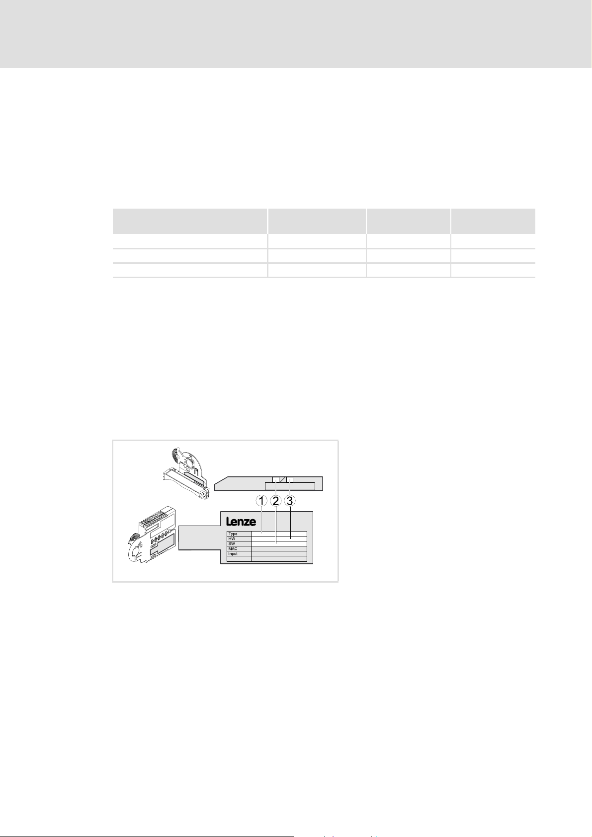
3.2 Identification
The type designation and hardware and software version of the communication module
are specified on the nameplate:
E94YCDN005
version
1 Type designation (type)
E94 Product series
AVersion
Y Module identification: Extension module
C Module type: Communication module
EN Ethernet
2 Hardware version (HW)
3 Software version (SW)
From software
version
[3-1] Identification data
EDS94AYCEN EN 9.0 - 09/2012 L 13
Page 14
E94AYCEN communication manual (Ethernet)
Product description
Product features
3.3 Product features
Interface module for the Ethernet communication system, for attaching to the
expansion slots of the Servo Drives 9400
2-port interface with integrated switch functionality
Automatic setting of baud rate and transmission mode (auto-negotiation)
Automatic detection of wiring errors and polarity reversal of data signals (auto-
polarity)
Automatic detection and (internal) swapping of data signals from receive paths and
transmit paths (auto-crossing)
Access to all Lenze parameters via the Lenze »Engineer«
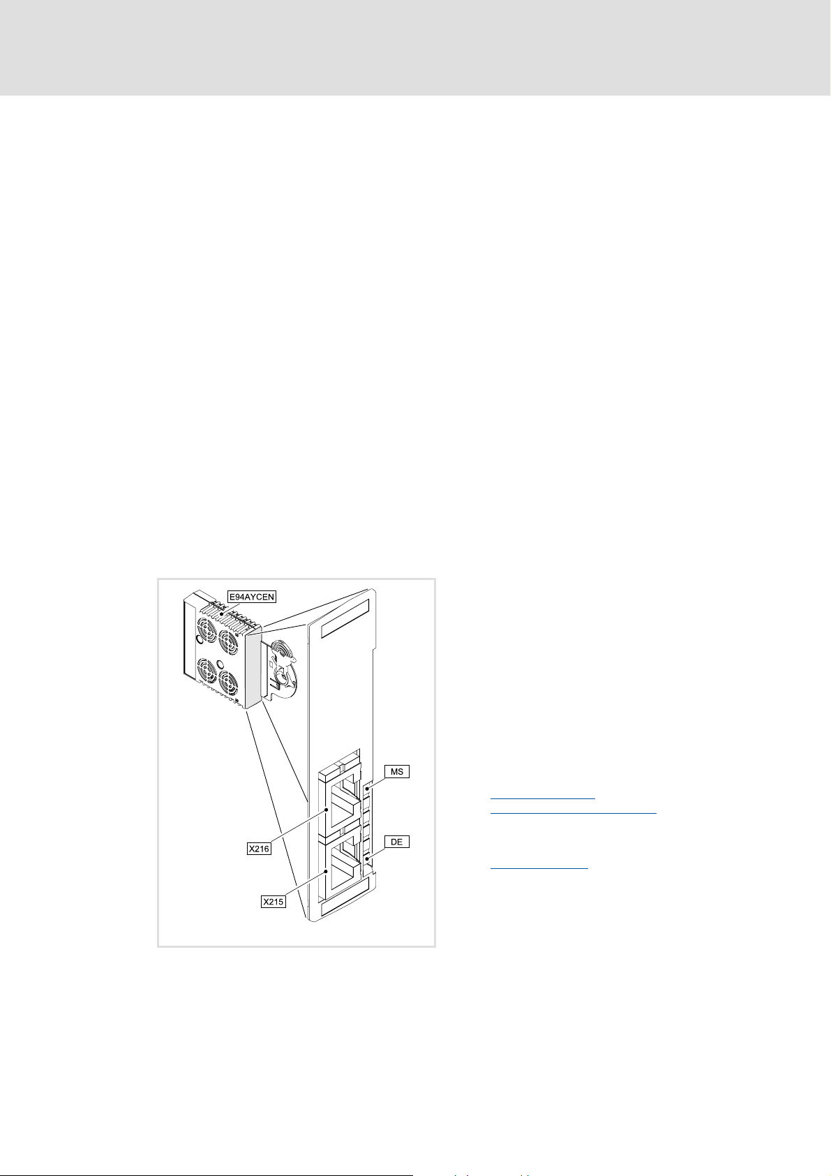
3.4 Terminals and interfaces
2 RJ45 sockets for Ethernet connection
Front LEDs for diagnosing the ...
– Voltage supply of the communication module
– Connection to the standard device
– Ethernet connection
– Ethernet activity
X215
X216
MSDE2 LED status displays for diagnostics
Ethernet connections
• RJ45 sockets
• Each with 2 LED status displays for diagnostics
Ethernet connection
Status display at
LED status displays
( 22)
X215 and X216 ( 52)
( 52)
E94YCEN001A
[3-2] Communication module E94AYCEN (Ethernet)
14 L EDS94AYCEN EN 9.0 - 09/2012
Page 15

E94AYCEN communication manual (Ethernet)
4 Technical data
4.1 General data and operating conditions
Area Values
Order designation E94AYCEN
Communication profile GCI, based on TCP/IP
Communication medium S/FTP (screened foiled twisted pair, ISO/IEC 11801 or EN 50173), CAT 5e
Interface RJ45: Standard Ethernet (in accordance with IEEE 802.3), 100Base-TX (Fast
Ethernet)
Network topology Line, star
Ethernet port 9410 (GCI)
Baud rate • 10 Mbps
• 100 Mbps
Transmission mode Half duplex / full duplex
Switching method Store and forward
Switch latency 125 μs at maximum telegram length
Voltage supply The communication module is solely supplied with voltage by the standard
device.
Conformities, approvals • CE
•UL
Technical data
General data and operating conditions
Servo Drives 9400 hardware manual
This manual contains data on ambient conditions and the electromagnetic
compatibility (EMC) which also apply to the communication module.
EDS94AYCEN EN 9.0 - 09/2012 L 15
Page 16

E94AYCEN communication manual (Ethernet)
Technical data
Protective insulation
4.2 Protective insulation
Danger!
Dangerous electrical voltage
If Servo Drives 9400 are used on a phase earthed mains with a rated mains
voltage ≥ 400 V, protection against accidental contact is not guaranteed
without external measures.
Possible consequences:
• Death or severe injuries
Protective measures:
• If protection against accidental contact is required for the control terminals
of the drive and for the connections of the plugged-in device modules, ...
– a double isolating distance must exist.
– the components to be connected must be provided with the second
isolating distance.
Note!
The protective insulation provided in Servo Drives 9400 is implemented in
accordance with EN 61800-5-1.
16 L EDS94AYCEN EN 9.0 - 09/2012
Page 17
E94AYCEN communication manual (Ethernet)
Technical data
Protective insulation
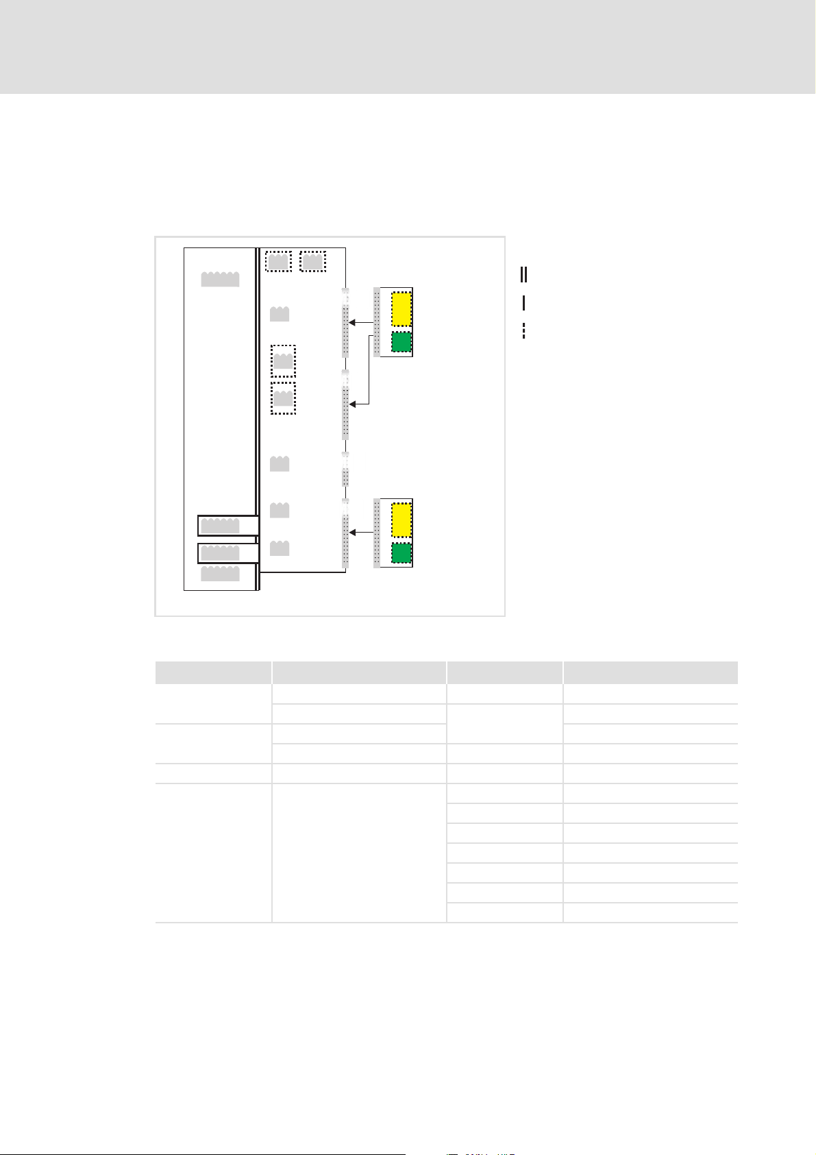
The following illustration ...
shows the arrangement of the terminal strips and the separate potential areas of the
drive.
serves to determine the decisive protective insulation between two terminals located
in differently insulated separate potential areas.
X2
X100
X1
X3
X4
X5
MXI1
Bus
Ext. DC
MXI2
Reinforced insulation
Basic insulation
Functional insulation
X6X6
X7X7
X107
X106
X105X105
[4-1] Protective insulation in accordance with EN61800-5-1
Terminal strip Connection Terminal strip Connection
X8X8
X100 L1, L2, L3 (Single Drive only) X1 CAN on board 9400
+UG, -UG X2 Statebus
X105 U, V, W 24 V (ext.)
Rb1, Rb2 (Single Drive only) X3 Analog inputs/outputs
X106 Motor PTC X4 Digital outputs
X107 Control of the motor holding
brake
MMI
MSI
I/O
Ext. DC
E94YCXX007
X5 Digital inputs
X6 Diagnostics
X7 Resolver
X8 Encoder
MXI1, MXI2 Extension module
MMI Memory module
MSI Safety module
EDS94AYCEN EN 9.0 - 09/2012 L 17
Page 18
E94AYCEN communication manual (Ethernet)
Technical data
Dimensions
Example
Which type of protective insulation is used between the bus terminal of the device module
in slot MXI1 or MXI2 and the mains terminal X100?
The separate potential area with the better protective insulation is decisive.
– The separate potential area of the bus terminal of the device module has a
"functional insulation".
– The separate potential area of the mains terminal has a "reinforced insulation".
Result: The insulation between mains terminal X100 and the bus terminal is of the
"reinforced insulation" type.
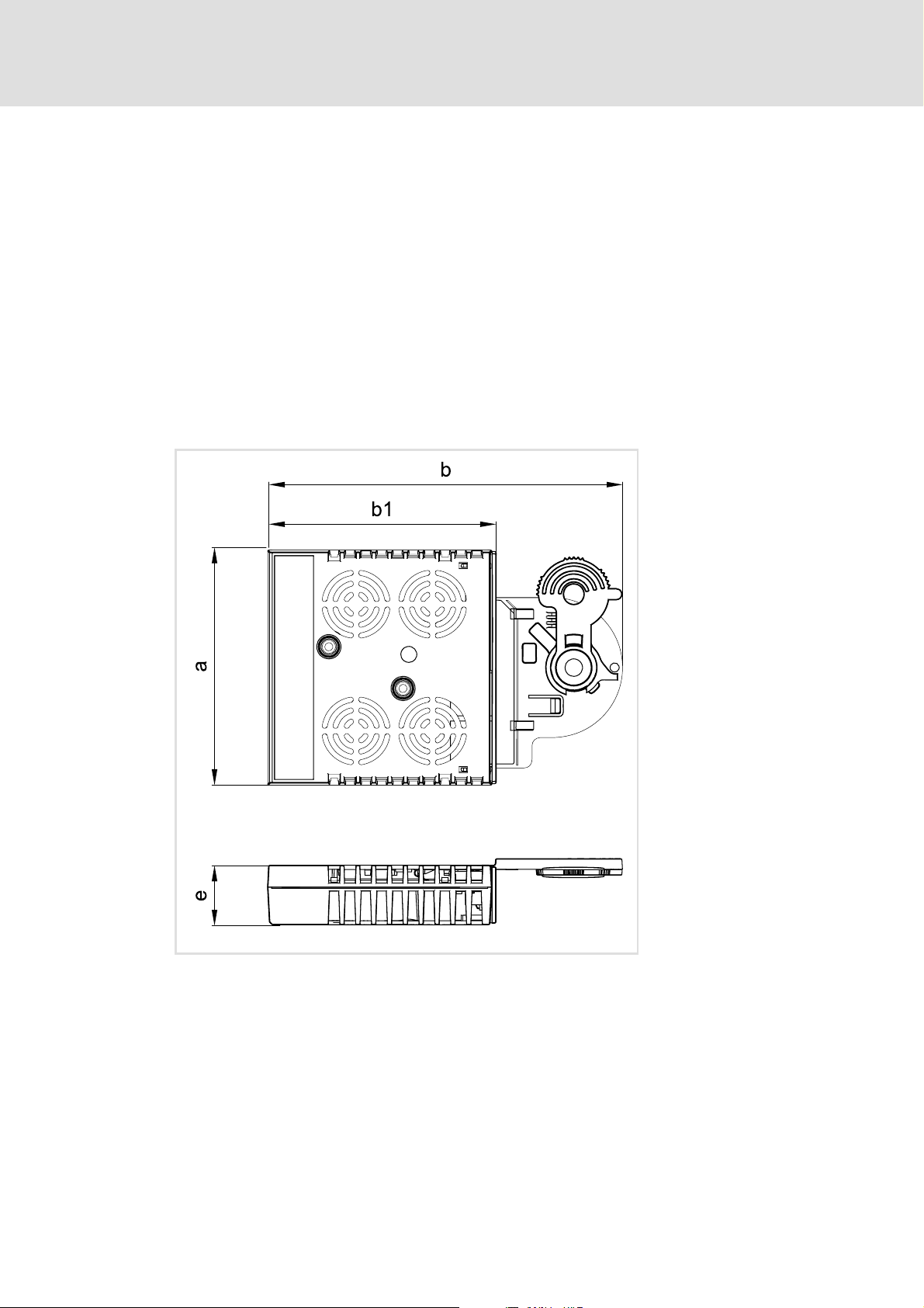
4.3 Dimensions
a 89 mm
b 134 mm
b1 87 mm
e 23 mm
E94YCXX005
[4-2] Dimensions
18 L EDS94AYCEN EN 9.0 - 09/2012
Page 19

5 Installation
Stop!
Electrostatic discharge
Electronic components within the communication module can be damaged or
destroyed by electrostatic discharge.
Possible consequences:
• The communication module is damaged.
• Fieldbus communication is not possible or faulty.
Protective measures
• Before touching the module, be sure that you are free of electrostatic charge.
E94AYCEN communication manual (Ethernet)
Installation
EDS94AYCEN EN 9.0 - 09/2012 L 19
Page 20
E94AYCEN communication manual (Ethernet)
Installation
Mechanical installation
5.1 Mechanical installation
Note!
Only one Ethernet module may be attached to a Servo Drive 9400, either in
module slot MXI1 or
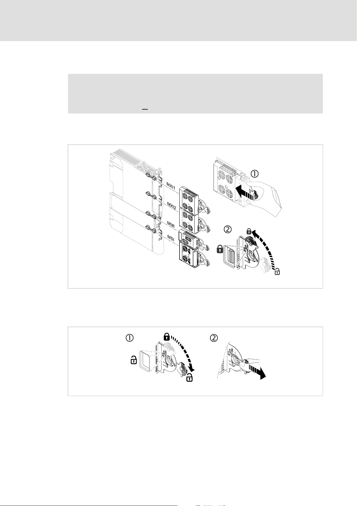
5.1.1 Assembly
MXI2.
[5-1] Assembly
5.1.2 Disassembly
[5-2] Disassembly
E94YCXX001G
E94AYCXX001H
20 L EDS94AYCEN EN 9.0 - 09/2012
Page 21
5.2 Electrical installation
Documentation for the standard device, control system, system/machine
Observe the notes and wiring instructions contained in this documentation.
5.2.1 EMC-compliant wiring
In typical systems, standard shielding is sufficient for Ethernet cables.
However, in environments with a very high level of interference, EMC resistance can be
improved by additionally earthing the cable shield on both sides.
For this observe the following notes:
1. The distance between the additional earthing and the Ethernet plug depends on the
module slot and is as follows:
– Approx. 10 cm for the upper slot (MXI1)
– Approx. 20 cm for the lower slot (MXI2)
E94AYCEN communication manual (Ethernet)
Installation
Electrical installation
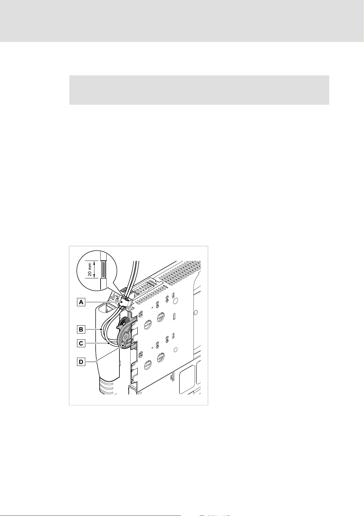
2. Measure the appropriate distance along the cable and, starting from this point, remove
2 cm of the cable's plastic sheath.
3. Fasten the cable shield onto the shield sheet of the Servo Drive 9400.
A Fastening on the shield sheet of the Servo Drive
9400
B Outgoing Ethernet cable at X216
C Incoming Ethernet cable at X215
D Communication module in slot MXI1 of the
Servo Drive 9400
E94YCXX008
[5-3] EMC-compliant wiring
EDS94AYCEN EN 9.0 - 09/2012 L 21
Page 22

E94AYCEN communication manual (Ethernet)
Installation
Electrical installation
5.2.2 Ethernet connection
The Ethernet connection is made via the RJ45 sockets X215 and X216.
You can use a standard Ethernet patch cable to connect the communication module to
the Ethernet fieldbus.
Specification of the Ethernet cable
( 23)
Note!
• Decouple your Ethernet house network from the system network for
Ethernet-capable Lenze devices in order to prevent trouble in the Ethernet
communication.
Further information can be obtained from the "Ethernet in the industrial
application" manual.
• To prevent the RJ45 socket from being damaged, hold the Ethernet cable
connector straight (at a right angle) when inserting it into or removing it from
the socket.
Pin assignment
RJ45 socket Pin Signal
1Tx +
2Tx -
3Rx +
4-
5-
6Rx -
E94AYCXX004C
7-
8-
Tip!
The Ethernet interfaces feature an auto MDIX function. This function adjusts the
polarity of the RJ45 interfaces so that a connection is established irrespective of the
polarity of the opposite Ethernet interface, and irrespective of the type of cable
used (standard patch cable or crossover cable).
22 L EDS94AYCEN EN 9.0 - 09/2012
Page 23

E94AYCEN communication manual (Ethernet)
Free space
When ordering and using your Ethernet cable, note the amount of free space available.
[5-4] Free space
5.2.3 Specification of the Ethernet cable
Installation
Electrical installation
E94YCET017
Note!
Only use cables that meet the listed specifications.
Specification of the Ethernet cable
Ethernet standard Standard Ethernet (in accordance with IEEE 802.3), 100Base-TX (Fast
Ethernet)
Cable type S/FTP (Screened Foiled Twisted Pair), ISO/IEC 11801 or EN 50173, CAT 5e
Damping 23.2 dB (at 100 MHz and per 100 m)
Crosstalk damping 24 dB (at 100 MHz and per 100 m)
Return loss 10 dB (per 100 m)
Surge impedance 100 Ω
Structure of the Ethernet cable
A Cable insulation
B Braid
C Foil shield
TP1
Twisted core pairs 1 ... 4
...
Colour coding of the Ethernet cable
TP4
( 24)
E94YCEP016
[5-5] Structure of the Ethernet cable (S/FTP, CAT 5e)
EDS94AYCEN EN 9.0 - 09/2012 L 23
Page 24

E94AYCEN communication manual (Ethernet)
Installation
Electrical installation
Colour coding of the Ethernet cable
Note!
Wiring and colour code are standardised in EIA/TIA 568A/568B.
In accordance with the industrial standard, the use of 4-pin Ethernet cables is
permissible. The cable type only connects the assigned pins 1, 2, 3 and 6 to one
another.
E94YCEI004A
[5-6] Ethernet plug in accordance with EIA/TIA 568A/568B
Pair Pin Signal EIA/TIA 568A EIA/TIA 568B
3 1 Tx + white / green white / orange
2 Tx - green orange
2 3 Rx + white / orange white / green
1 4 blue blue
5 white / blue blue / white
2 6 Rx - orange green
4 7 white / brown white / brown
8brown brown
24 L EDS94AYCEN EN 9.0 - 09/2012
Page 25

5.2.4 Voltage supply
Internal supply
The communication module is solely supplied with voltage by the standard device.
Note!
If the standard device fails and daisy-chain wiring has been used, the
transmission of data between the Ethernet nodes at interface X215 and the
Ethernet nodes at interface X216 will be interrupted.
E94AYCEN communication manual (Ethernet)
Installation
Electrical installation
EDS94AYCEN EN 9.0 - 09/2012 L 25
Page 26

E94AYCEN communication manual (Ethernet)
Commissioning
Before initial switch-on
6 Commissioning
During commissioning, system-related data such as motor parameters, operating
parameters, responses, and parameters for fieldbus communication are defined for the
drive. For Lenze devices, this is done via the codes.
The codes of the drive and for communication are saved non-volatilely as a data set in the
memory module.
In addition to codes for the configuration, there are codes for diagnosing and monitoring
the nodes.
Note!
When parameterising the communication module, please note that the code
number depends on the slot of the Servo Drive 9400 into which the
communication module is plugged.
The first two digits of the code number indicate the slot:
•C13nnn for slot MXI1
Parameters of the communication module for slot MXI1
•C14nnn for slot MXI2
Parameters of the communication module for slot MXI2
Additionally set the Parameters of the standard device that are relevant to
communication ( 54).
6.1 Before initial switch-on
Stop!
Before switching on the Servo Drive 9400 and the communication module for
the first time, check the entire wiring for completeness, short circuit and earth
fault.
( 56)
( 60)
26 L EDS94AYCEN EN 9.0 - 09/2012
Page 27

E94AYCEN communication manual (Ethernet)
6.2 Configuring the communication module
The address settings required for Ethernet operation are displayed in the »Engineer« in the
Settings tab (Fig. [6-1]
Parameter Code Lenze setting
IP address C13000/1...4
Subnet mask C13001/1...4
Standard gateway C13002/1...4
Physical address (MAC) C13003/1...6
). The settings correspond to the values of the codes:
for slot MXI1 for slot MXI2
Commissioning
Configuring the communication module
C14000/1...4 127.0.0.1
C14001/1...4 255.255.255.0
C14002/1...4 127.0.0.1
C14003/1...6 00-00-00-00-00-00
[6-1] Ethernet address settings
You can set the IP address ( 31), the Subnet mask ( 31) and the Gateway address ( 32)
manually, but the IP address can also be received automatically from a DHCP server.
Setting the address
Automatically receiving an IP address
( 28)
( 29)
EDS94AYCEN EN 9.0 - 09/2012 L 27
Page 28

E94AYCEN communication manual (Ethernet)
Commissioning
Configuring the communication module
6.2.1 Setting the address
Clicking the Change button in the Settings tab (Fig. [6-1]
dialog window:
[6-2] Setting the address
In the input fields for the IP address, the subnet mask and the standard gateway, you can
directly set the addresses.
) opens the "Configure IP address"
Setting the standard device code C00002 to "101: bind/unbind" or "102: bind/unbind"
copies the values and writes them to the corresponding codes:
Parameter Code
for slot MXI1 for slot MXI2
IP address C13000/1...4
Subnet mask C13001/1...4 C14001/1...4
Standard gateway C13002/1...4 C14002/1...4
The codes can also be set via the parameter list of the Servo Drive 9400 (All parameters
tab).
C14000/1...4
Tip!
You can use a ping command in the MS-DOS input window to test whether the
entered IP address is valid or not.
28 L EDS94AYCEN EN 9.0 - 09/2012
Page 29

E94AYCEN communication manual (Ethernet)
6.2.2 Automatically receiving an IP address
Commissioning
Configuring the communication module
Clicking the Change button in the Settings tab (Fig. [6-1]
dialog window.
Mark "Receive IP address automatically" in order to receive an IP address automatically
from the DHCP server:
[6-3] Automatically receiving an IP address
) opens the "Configure IP address"
The input field for the standard gateway serves to manually enter a gateway address. By
default, the current values of the corresponding codes are displayed.
Setting the standard device code C00002 to "101: bind/unbind" or "102: bind/unbind"
copies the values and writes them to the corresponding codes:
Parameter Code
for slot MXI1 for slot MXI2
IP address C13000/1...4
Use of DHCP C13005 C14005
The codes can also be set via the parameter list of the Servo Drive 9400 (All parameters
tab).
C14000/1...4
Note!
Observe the information given in chapter DHCP implementation in the Servo
Drive 9400 ( 34).
Tip!
You can use a ping command in the MS-DOS input window to test whether the
received IP address is valid or not.
EDS94AYCEN EN 9.0 - 09/2012 L 29
Page 30

E94AYCEN communication manual (Ethernet)
Commissioning
Configuring the communication module
Output of the »Network Analyzer«
With "DHCP ACK", the DHCP server (here IP address "192.216.31.1") assigns the IP address
"192.216.31.239" to the Servo Drive 9400 (DHCP client):
30 L EDS94AYCEN EN 9.0 - 09/2012
Page 31

6.2.3 IP address
The IP address is required for addressing the Servo Drive 9400 if communication between
the PC and the controller is to be established via an Ethernet connection.
The IP address consists of four numbers between 0 and 255 which respectively are
separated from each other by a point, e. g. "192.168.10.1".
Eight bits are reserved for each of the four numbers, which makes a total of 32 bits.
The first one, two, or three numbers indicate the network (Net-ID), the remaining
numbers indicate the host (Host-ID). The definite specification of the part that is to be
evaluated as Net-ID is effected via the Subnet mask
Codes
E94AYCEN communication manual (Ethernet)
Commissioning
Configuring the communication module
( 31).
Parameter (MXI1): C13000/1 C13000/2 C13000/3 C13000/4
Lenze setting 127 . 0.0.1
Parameter (MXI2): C14000/1
6.2.4 Subnet mask
The subnet mask indicates which part of the IP address is evaluated as net ID or host ID.
The subnet mask consists of four numbers which are separated by a point, e.g.
"255.255.255.0".
Eight bits are reserved for each of the four numbers, which makes a total of 32 bits.
Examples
1. The first three numbers of the IP address indicate the network, the last number
indicates the host (Lenze setting):
Subdivision of IP address: Net ID Host ID
2. The first two numbers of the IP address indicate the network, the last two numbers
indicate the host:
Subdivision of IP address:
C14000/2 C14000/3 C14000/4
Lenze setting 127 . 0.0.1
Subnet mask:
Subnet mask:
255 . 255 . 255 . 0
255 . 255 . 0.0
Net ID Host ID
3. The first number of the IP address indicates the network, the remaining three numbers
indicate the host:
Subnet mask:
Subdivision of IP address:
EDS94AYCEN EN 9.0 - 09/2012 L 31
255 . 0.0.0
Net ID Host ID
Page 32

E94AYCEN communication manual (Ethernet)
Commissioning
Configuring the communication module
Codes
Parameter (MXI1): C13001/1 C13001/2 C13001/3 C13001/4
Lenze setting 255 . 255 . 255 . 0
Parameter (MXI2): C14001/1
6.2.5 Gateway address
The gateway address is required if the Servo Drive 9400 is not located in the same
subnetwork as the PC.
The gateway address consists of four numbers between 0 and 255, separated by
points, e.g. "127.0.0.0".
Eight bits are reserved for each of the four numbers, which makes a total of 32 bits.
Codes
Parameter (MXI1): C13002/1 C13002/2 C13002/3 C13002/4
Parameter (MXI2): C14002/1
C14001/2 C14001/3 C14001/4
Lenze setting 255 . 255 . 255 . 0
Lenze setting 127 . 0.0.1
C14002/2 C14002/3 C14002/4
Lenze setting 127 . 0.0.1
6.2.6 MAC-ID
The MAC-ID is a globally unique identifier of an Ethernet-capable device. The MAC-ID is
assigned by the manufacturer and permanently burnt into the device (Lenze
communication module).
The MAC-ID consists of six hexadecimal numerical codes (00 ... FF) which respectively
are separated from each other by a hyphen, e. g. "00-0A-86-00-00-0A".
Eight bits are reserved for each one of the six numerical codes, which makes a total
48 bits.
The MAC-ID consists of the manufacturer's identification mark and a running number
which is clearly assigned by the manufacturer.
32 L EDS94AYCEN EN 9.0 - 09/2012
Page 33

Display of the MAC-ID
E94AYCEN communication manual (Ethernet)
Commissioning
Configuring the communication module
The MAC-ID of the communication module is displayed in C13003
Parameter (MXI1):
Display [hex]: 00 - 0A - 86 - xx - xx - xx
Parameter (MXI2):
Display [hex]: 00 - 0A - 86 - xx - xx - xx
C13003/1 C13003/2 C13003/3 C13003/4 C13003/5 C13003/6
Manufacturer's identification mark
(Lenze)
C14003/1 C14003/2 C14003/3 C14003/4 C14003/5 C14003/6
Manufacturer's identification mark
(Lenze)
Consecutive definite number
Consecutive definite number
Tip!
The MAC ID is also entered in the nameplate of the communication module:
/C14003:
EDS94AYCEN EN 9.0 - 09/2012 L 33
Page 34

E94AYCEN communication manual (Ethernet)
Commissioning
DHCP implementation in the Servo Drive 9400
6.3 DHCP implementation in the Servo Drive 9400
DHCP is the acronym for "Dynamic Host Configuration Protocol". This protocol is defined in
RFC 2131 and is an advancement on BOOTP (RFC 951). DHCP enables computers to query
information about the network configuration (e.g. IP address) from a server via a TCP/IP
network. The DHCP server assigns the IP address to the client dynamically, from a defined
address range. This means that the client always receives a new, but unique IP address.
DHCP is implemented in the firmware (program organisation unit RTCS). The following
chapter describes how the Servo Drive 9400 receives an IP address via DHCP.
DHCP code
For standard devices from version V03.xx.xx.xx, the DHCP codes C13005
available. These codes can be used to define whether DHCP is to be used or not:
Value 0 (FALSE): Do not use DHCP (Lenze setting)
Value 1 (TRUE): Use DHCP
DHCP flag settings
UseIPfromDhcp = TRUE (Use DHCP):
The IP settings are assigned by the DHCP server.
UseIPfromDhcp = FALSE (Do not use DHCP):
The IP settings are assigned manually.
6.3.1 Basic terms
DHCP client
TCP/IP stack of a host. Network node that makes DHCP requests and is configured.
DHCP server
Network node that waits for DHCP requests and responds to them.
and C14005 are
Lease time
Service life of the assigned IP address. After this period expires, the IP address will be
invalid. If it still needs to be used after this period, the lease time must be extended.
34 L EDS94AYCEN EN 9.0 - 09/2012
Page 35

6.3.2 DHCP network architecture
Data relating to the DHCP network architecture
DHCP model Client/Server
Transport protocol UDP
Ports Server - UDP port 67
DHCP packet size 576 bytes
Compatibility DHCP is an advancement on BOOTP, so the DHCP server can also manage
6.3.3 DHCP operating mode
DHCP is a client-server architecture. The DHCP server has access to a pool of IP addresses,
which it can freely assign to the DHCP clients. For larger networks, the DHCP server also
needs to know which subnetworks and gateways are available.
E94AYCEN communication manual (Ethernet)
Commissioning
DHCP implementation in the Servo Drive 9400
Client - UDP port 68
BOOTP clients.
[6-4] DHCP operating mode
In the first step, the client transmits a "DHCP discover broadcast", which searches for
the server.
The server responds to the client with a "DHCP offer" (unicast). This message contains
the IP address, subnet mask, lease time and other information for the client.
The client then accepts this data and reports this situation to the server by means of a
"DHCP request" message.
The server completes the DHCP configuration with a "DHCP acknowledge" message.
This message contains the server IP address, client IP address, lease time, subnet mask
and other configuration information.
DHCP-
Client
DHCP-Discover
DHCP-Offer
DHCP-Request
DHCP-Acknowledge
DHCPServer
E94YCEN020
EDS94AYCEN EN 9.0 - 09/2012 L 35
Page 36

E94AYCEN communication manual (Ethernet)
Commissioning
DHCP implementation in the Servo Drive 9400
6.3.4 DHCP packet structure
The DHCP packets have the following structure:
Bit 1 ... 8 Bit 9 ... 16 Bit 17 ... 24 Bit 25 ... 32
op (1 byte) htype (1 byte) hlen (1 byte) hops (1 byte)
xid (4 bytes)
secs (2 bytes) flags (2 bytes)
ciaddr (4 bytes)
yiaddr (4 bytes)
siaddr (4 bytes)
giaddr (4 bytes)
chaddr (4 bytes)
sname (4 bytes)
file (4 bytes)
options (variable)
Description of the fields:
Field Size Description
op 1 Byte Opcode: Task carried out by the DHCP packet
• Indicates a client request or a server response.
htype 1 Byte Hardware type: Specification of the network topology
• Examples: 1 for Ethernet, 15 for Frame Relay (specification in RFC 1700)
hlen 1 Byte Hardware address length: Length of the hardware address in the "chaddr"
hops 1 Byte Hop count: Number of routers / gateways between the client and the server
xid 4 bytes Transaction ID: Unique identifier generated by the client
secs 2 bytes Number of seconds: Time in seconds that has elapsed since the DHCP
flags 2 bytes Flags: The first bit is used as a broadcast flag. All other flags are reserved for
ciaddr 4 bytes Client IP address: Most recently used client IP address
yiadr 4 bytes Your IP address: IP address assigned to the client by the server
siaddr 4 bytes Server IP address: IP address of the server
giaddr 4 bytes Gateway IP address: This field enables the client to communicate with
chaddr 4 bytes Client hardware address: MAC address of the client
sname 4 bytes Server host name: This field is optional and can contain the server name.
file 4 bytes Boot filename: The client defines the full path for its boot file here.
options Variable
(1 to 4 bytes)
(client hardware address) field
• This is required in order to assign a DHCP response to the corresponding
DHCP request.
process began
later use (status = 0).
• This is only used in a client DHCP request.
• This is only used in a server DHCP response.
• This is only used in a server DHCP response.
servers in other DHCP subnetworks.
• IP address "0.0.0.0" in a client request
• A DHCP relay agent enters its IP address here.
Options: This field contains additional information for the client.
• The specification of the DHCP message type, for example, is very
important.
• Defined in full in RFC 2132
36 L EDS94AYCEN EN 9.0 - 09/2012
Page 37

6.4 Initial switch-on
Documentation for the standard device
Observe the safety instructions and information on residual hazards.
Note!
Activate changed settings
To activate changed settings ...
• execute the device command "11: Save start parameters" via standard device
code C00002 and ...
• then reset the bus node or switch off and on again the voltage supply of the
communication module.
E94AYCEN communication manual (Ethernet)
Commissioning
Initial switch-on
Protection against uncontrolled restart
After a fault (e.g. short-term mains failure), it is sometimes undesirable or even
impermissible for the drive to restart.
In the Lenze setting of Servo Drives 9400, the restart protection is activated.
The restart behaviour of the controller can be set using C00142 ("Auto-restart
following mains connection"):
• C00142 = "0: Inhibited" (Lenze setting)
– The drive remains inhibited (even if the fault is no longer active).
– An explicit controller enable causes the drive to start up in a controlled
manner: LOW-HIGH edge at digital input X5/RFR.
• C00142 = "1: Enabled"
– An uncontrolled restart of the drive is possible.
EDS94AYCEN EN 9.0 - 09/2012 L 37
Page 38

E94AYCEN communication manual (Ethernet)
Parameter data transfer
7 Parameter data transfer
The PC (client) used for setting parameters and the controller (server) communicate with
one another by exchanging data telegrams via the Ethernet. The parameter data are
contained in the user data area of the data telegram.
Parameters are set, for instance, when the system is initially adjusted during
commissioning or when the material of the production machine is changed.
The parameter data are transmitted as SDOs (Service Data Objects) and confirmed by
the receiver, i.e. the transmitter receives a feedback whether the transmission was
successful.
The SDOs provide for the write and read access to the object directory in the controller.
The transmission of the parameter data usually is not time-critical.
The parameter data are saved in Lenze devices as "codes".
Via the codes, for instance operating parameters, motor data or diagnostics
information can be set.
[7-1] Data communication according to the client/server model
Note!
With regard to the writing access on parameter data, observe that the changes
carried out are not stored automatically in the controller.
In order to save changed parameter settings with mains failure protection, carry
out the device command C00002 = "11: Save start parameters".
38 L EDS94AYCEN EN 9.0 - 09/2012
Page 39

E94AYCEN communication manual (Ethernet)
7.1 Structure of the Ethernet data telegram
The GCI protocol is used for communication.
The Ethernet data telegram is shown below. Here, the GCI header represents the part of
the program that is independent of the type of command transmitted.
Parameter data transfer
Structure of the Ethernet data telegram
Ethernet
Header
GMT
[7-2] Structure of the GCI header within the Ethernet frame
GSV
IP Header
rspa
GMQ
TCP/IP
Header
res
Field Size Description
GMT 1 Byte GCI message type
0x01 Reserved
GSV 1 Byte GCI service identification
0x82 Reading parameters
0x83 Writing parameters
GMQ 1 Byte GCI message qualifier
Bit 7
Bit 6 Bit 5 ... Bit 0
rsp a
rsp Request/response (1 bit)
0: request
1: response
aAbort (1 bit)
0: data transmission ok
1: data transmission aborted
res Reserved (6 bits)
Data contents = 0
GTI 1 Byte GCI transaction ID
0x00 Serial number (transaction identification)
• For each client a definite serial number (0 ... 255) is allocated.
...
• The serial number in the multitasking environment is used for
0xFF
SIZE 2 bytes User data length (P0, P1, P2, P3, P4)
0x14 20 bytes
... ...
0x114 276 bytes
res 2 bytes Reserved
0x0000 Data contents = 0
GCI Header
SIZEGTI
res
P0…P4
SIZE res res
Ethernet
CRC
referencing to the calling tasks (reverse transaction).
E94YCEN015
EDS94AYCEN EN 9.0 - 09/2012 L 39
Page 40

E94AYCEN communication manual (Ethernet)
Parameter data transfer
Reading parameters from the controller
Tip!
The GCI header will be described in greater detail during the course of this manual.
The other signals refer to the transfer characteristics of the Ethernet telegram,
which are not described in this documentation.
7.2 Reading parameters from the controller
With the service identification (GSV) = 0x82 in the GCI header parameter data can be read
from the controller:
Client Server
(PC) Request (9400)
Request GMT GSV GMQ GTI SIZE SIZE res res User data Indication
0x01 0x82 0x00 0xXX 0xXX 0xXX 0x00 0x00
Confirmation GMT GSV GMQ GTI SIZE SIZE res res User data
0x01 0x82 0x80 0xXX 0xXX 0xXX 0x00 0x00
7.3 Writing parameters to the controller
With the service identification (GSV) = 0x83 in the GCI header parameter data can be
written to the controller:
Client Server
(PC) Request (9400)
Request GMT GSV GMQ GTI SIZE SIZE res res User data Indication
0x01 0x83 0x00 0xXX 0xXX 0xXX 0x00 0x00
Confirmation GMT GSV GMQ GTI SIZE SIZE res res User data
0x01 0x83 0x80 0xXX 0xXX 0xXX 0x00 0x00
Response
Response
(error code)
(error code)
Response
Response
40 L EDS94AYCEN EN 9.0 - 09/2012
Page 41

E94AYCEN communication manual (Ethernet)
7.4 Assignment of user data areas P0 ... P4
Area Byte 1 Byte 2 Byte 3 Byte 4
P0 Status/error code Data type Reserved
P1 Code Reserved Reserved
P2 Subcode Reserved Reserved*
P3 Parameter value
P4 Parameter value
* When the data type VISIBLE_STRING is transmitted, byte 4 contains the number of the characters attached.
Data type in P0 / byte 3
ID Data type Data length
0x01 INTEGER_8 1 byte
0x02 INTEGER_16 2 bytes
0x03 INTEGER_32 4 bytes
0x04 INTEGER_64 8 bytes
0x05 UNSIGNED_8 1 byte
0x06 UNSIGNED_16 2 bytes
0x07 UNSIGNED_32 4 bytes
0x08 UNSIGNED_64 8 bytes
0x09 FLOATING_POINT 4 bytes
0x0A VISIBLE_STRING 256 bytes (max.)
0x0B OCTET_STRING 256 bytes (max.)
0x0C BITFIELD_8 1 byte
0x0D BITFIELD_16 2 bytes
0x0E BITFIELD_32 4 bytes
0x0F FIXPOINT_16 2 bytes
0x10 FIXPOINT_32 4 bytes
Parameter data transfer
Assignment of user data areas P0 ... P4
EDS94AYCEN EN 9.0 - 09/2012 L 41
Page 42

E94AYCEN communication manual (Ethernet)
Parameter data transfer
Transmission abort
Assignment of the User data area with parameter values of different data lengths
Depending on the data format, the parameter value occupies 1 to 8 bytes. Data are stored
in little-endian format, i.e. first the low byte or low word, then the high byte or high word:
Data length Data area P3 Data area P4
Byte 1 Byte 2 Byte 3 Byte 4 Byte 1 Byte 2 Byte 3 Byte 4
1 byte
Value 00 00 00 00 00 00 00
2 bytes
4 bytes
8 bytes
7.5 Transmission abort
The transmission is either aborted by the client or the server of a parameter data telegram.
The message is aborted without confirmation. If the SDO client awaits the message to be
confirmed, it will receive an abort message instead.
Low byte High byte
Value
Double word
Low word High word
Low byte High byte Low byte High byte
Lower-order double word Higher-order double word
Low word High word Low word High word
Low byte High byte Low byte High byte Low byte High byte Low byte High byte
00 00 00 00 00 00
00 00 00 00
Value
Value
42 L EDS94AYCEN EN 9.0 - 09/2012
Page 43

7.6 Error codes
The error code is located in the User data area P0, byte 1 and byte 2.
User data area P0
Byte 1 Byte 2 Byte 3 Byte 4
Example error code 0x9002
Low byte High byte
0x02 0x90
Note!
The other user data contents correspond to those of an error-free message.
Possible error codes
E94AYCEN communication manual (Ethernet)
Parameter data transfer
Error codes
Error code Data type Reserved
Error code Definition Description
dec hex
33803 0x840B Invalid type Invalid parameter type
33805 0x840D FB not found Function block not found
33812 0x8414 Invalid size Invalid parameter format
33813 0x8415 Not in select list Parameter is not in the selection list
33814 0x8416 Read not allowed Parameter read is not allowed
33815 0x8417 Write not allowed Parameter write is not allowed
33816 0x8418 CINH not set Controller inhibit is not set
33817 0x8419 PLC not stopped The PLC is not in the "Stopped" status
33828 0x8424 Invalid index Invalid parameter index
33829 0x8425 Invalid subindex Invalid parameter subindex
33837 0x842D Access not allowed Parameter access not allowed
33848 0x8438 Invalid length Invalid parameter length
33862 0x8446 Unallowed characters Parameter contains invalid characters
33865 0x8449 No array parameter Parameter is no array parameter
33874 0x8452 Invalid select index Invalid selection index
36866 0x9002 No memory available No more memory available
36867 0x9003 No TID available No transaction ID (TID) available
anymore for identifying the telegram.
TIDs are released again after receiving a
reply with the corresponding TID.
36868 0x9004 Channel init error General error when opening the
communication channel
36869 0x9005 Error if not connected No connection could be established.
36870 0x9006 Error of send function Error when sending a GCI telegram
36871 0x9007 Error of receive function Error when receiving a GCI telegram
36872 0x9008 Timeout error of msg wait function No reply could be received to a request
within the timeout.
EDS94AYCEN EN 9.0 - 09/2012 L 43
Page 44

E94AYCEN communication manual (Ethernet)
Parameter data transfer
Error codes
Error code Definition Description
dec hex
36873 0x9009 Wrong GMT received The general telegram identification does
36874 0x900A Unknown server request Internal error in the GCI
36875 0x900B Wrong server parameter
36876 0x900C Server queue is full
36877 0x900D SRV send error
36878 0x900E SRV timeout
36879 0x900F Wrong client parameter
36880 0x9010 Wrong channel number
36881 0x9011 TX conversion error
36882 0x9012 RX conversion error
36883 0x9013 Retry number abort
36884 0x9014 Unknown client response
not correspond to the GCI
communication.
44 L EDS94AYCEN EN 9.0 - 09/2012
Page 45

E94AYCEN communication manual (Ethernet)
7.7 Telegram examples
7.7.1 Example 1: Querying the heatsink temperature (read request)
The heatsink temperature of the controller is to be read.
Code to be read: C00061
Assumption: ϑ = 43°C
Request
SDO command (GSV) = 0x82 = "Read parameter"
GCI message qualifier (GMQ) = 0x00 = 00000000B = "Request"
Transaction ID (GTI) here "0" (optional consecutive number 0 ... 255)
Length of the user data (SIZE) = 0x0014 = 20 bytes
Parameter data transfer
Telegram examples
GCI header
GMT GSV GMQ GTI SIZE SIZE res res
0x01 0x82 0x00 0x00 0x14 0x00 0x00 0x00
Fixed Reading
User data area P0
Byte 1 Byte 2 Byte 3 Byte 4
Reserved Reserved Data type Reserved
0x00 0x00 0x00 0x00
User data area P1 User data area P2
Byte 1 Byte 2 Byte 3 Byte 4 Byte 1 Byte 2 Byte 3 Byte 4
0x3D 0x00 0x00 0x00 0x00 0x00 0x00 0x00
Code = 61 = 0x003D Subcode = 0
User data area P3 User data area P4
Byte 1 Byte 2 Byte 3 Byte 4 Byte 1 Byte 2 Byte 3 Byte 4
0x00 0x00 0x00 0x00 0x00 0x00 0x00 0x00
parameters
Code Reserved Reserved Subcode Reserved Reserved
Reserved Reserved
Request Transactions ID Length of the user data = 20 bytes Reserved
Optional for
read request
EDS94AYCEN EN 9.0 - 09/2012 L 45
Page 46

E94AYCEN communication manual (Ethernet)
Parameter data transfer
Telegram examples
Response
GCI message qualifier (GMQ) = 0x80 = 10000000B = "Response"
GCI header
GMT GSV GMQ GTI SIZE SIZE res res
0x01 0x82 0x80 0x00 0x14 0x00 0x00 0x00
Fixed Reading
User data area P0
Byte 1 Byte 2 Byte 3 Byte 4
Reserved Reserved Data type Reserved
0x00 0x00 0x03 0x00
User data area P1 User data area P2
Byte 1 Byte 2 Byte 3 Byte 4 Byte 1 Byte 2 Byte 3 Byte 4
0x3D 0x00 0x00 0x00 0x00 0x00 0x00 0x00
Code = 61 = 0x003D Subcode = 0
parameters
Code Reserved Reserved Subcode Reserved Reserved
Response Transactions ID Length of the user data = 20 bytes Reserved
INTEGER_32
User data area P3 User data area P4
Byte 1 Byte 2 Byte 3 Byte 4 Byte 1 Byte 2 Byte 3 Byte 4
Parameter value of data type INTEGER_32 Reserved
0x00 0x00 0x00 0x2B 0x00 0x00 0x00 0x00
Read value = 0x0000002B = 43 [°C]
46 L EDS94AYCEN EN 9.0 - 09/2012
Page 47

E94AYCEN communication manual (Ethernet)
7.7.2 Example 2: Querying the firmware product type (read request)
The firmware product type of the controller is to be read.
Code to be read: C00200
Assumption: product type = "E94AFH"
Request
SDO command (GSV) = 0x82 = "Read parameter"
GCI message qualifier (GMQ) = 0x00 = 00000000B = "Request"
Transaction ID (GTI) here "1" (optional consecutive number 0 ... 255)
Length of the user data (SIZE) = 0x0014 = 20 bytes
GCI header
GMT GSV GMQ GTI SIZE SIZE res res
0x01 0x82 0x00 0x01 0x14 0x00 0x00 0x00
Fixed Reading
parameters
Request Transactions ID Length of the user data = 20 bytes Reserved
Parameter data transfer
Telegram examples
User data area P0
Byte 1 Byte 2 Byte 3 Byte 4
Reserved Reserved Data type Reserved
0x00 0x00 0x00 0x00
Optional for
read request
User data area P1 User data area P2
Byte 1 Byte 2 Byte 3 Byte 4 Byte 1 Byte 2 Byte 3 Byte 4
Code Reserved Reserved Subcode Reserved Reserved
0xC8 0x00 0x00 0x00 0x00 0x00 0x00 0x00
Code = 200 = 0x00C8 Subcode = 0
User data area P3 User data area P4
Byte 1 Byte 2 Byte 3 Byte 4 Byte 1 Byte 2 Byte 3 Byte 4
Reserved Reserved
0x00 0x00 0x00 0x00 0x00 0x00 0x00 0x00
EDS94AYCEN EN 9.0 - 09/2012 L 47
Page 48

E94AYCEN communication manual (Ethernet)
Parameter data transfer
Telegram examples
Response
GCI message qualifier (GMQ) = 0x80 = 10000000B = "Response"
GCI header
GMT GSV GMQ GTI SIZE SIZE res res
0x01 0x82 0x80 0x01 0x14 0x00 0x00 0x00
Fixed Reading
User data area P0
Byte 1 Byte 2 Byte 3 Byte 4
Reserved Reserved Data type Reserved
0x00 0x00 0x0A 0x00
User data area P1 User data area P2
Byte 1 Byte 2 Byte 3 Byte 4 Byte 1 Byte 2 Byte 3 Byte 4
0xC8 0x00 0x00 0x00 0x00 0x00 0x00 0x07
Code = 200 = 0x00C8 Subcode = 0 Number of the
parameters
Code Reserved Reserved Subcode Reserved Character
Response Transactions ID Length of the user data = 20 bytes Reserved
VISIBLE_STRING
length
characters
attached
User data area P3 User data area P4
Byte 1 Byte 2 Byte 3 Byte 4 Byte 1 Byte 2 Byte 3 Byte 4
Reserved Reserved
0x00 0x00 0x00 0x00 0x00 0x00 0x00 0x00
Note!
The parameter value read ("E94AFH") of data type VISIBLE_STRING follows
subsequent to the standard data area.
48 L EDS94AYCEN EN 9.0 - 09/2012
Page 49

E94AYCEN communication manual (Ethernet)
Parameter data transfer
Telegram examples
7.7.3 Example 3: Setting the deceleration time for quick stop (QSP) (write request)
The deceleration time for quick stop (QSP) is to be set to 50 ms in the controller.
Code to be written: C00105
Request
SDO command (GSV) = 0x83 = "Write parameter"
GCI message qualifier (GMQ) = 0x00 = 00000000B = "Request"
Transaction ID (GTI) here "42" (optional consecutive number 0 ... 255)
Length of the user data (SIZE) = 0x0014 = 20 bytes
GCI header
GMT GSV GMQ GTI SIZE SIZE res res
0x01 0x83 0x00 0x2A 0x14 0x00 0x00 0x00
Fixed Writing
parameters
Request Transactions ID Length of the user data = 20 bytes Reserved
User data area P0
Byte 1 Byte 2 Byte 3 Byte 4
Reserved Data type Reserved Reserved
0x00 0x00 0x07 0x00
UNSIGNED_32
User data area P1 User data area P2
Byte 1 Byte 2 Byte 3 Byte 4 Byte 1 Byte 2 Byte 3 Byte 4
Code Reserved Reserved Subcode Reserved Reserved
0x69 0x00 0x00 0x00 0x00 0x00 0x00 0x00
Code = 105 = 0x0069 Subcode = 0
User data area P3 User data area P4
Byte 1 Byte 2 Byte 3 Byte 4 Byte 1 Byte 2 Byte 3 Byte 4
Parameter value of data type UNSIGNED_32 Reserved
0x32 0x00 0x00 0x00 0x00 0x00 0x00 0x00
Value to be written = 0.05 [s] x 1000 (internal factor) = 50 = 0x32
EDS94AYCEN EN 9.0 - 09/2012 L 49
Page 50

E94AYCEN communication manual (Ethernet)
Parameter data transfer
Telegram examples
Response
GCI message qualifier (GMQ) = 0x80 = 10000000B = "Response"
GCI header
GMT GSV GMQ GTI SIZE SIZE res res
0x01 0x83 0x80 0x2A 0x14 0x00 0x00 0x00
Fixed Writing
User data area P0
Byte 1 Byte 2 Byte 3 Byte 4
Reserved Data type Reserved Reserved
0x00 0x00 0x07 0x00
User data area P1 User data area P2
Byte 1 Byte 2 Byte 3 Byte 4 Byte 1 Byte 2 Byte 3 Byte 4
0x69 0x00 0x00 0x00 0x00 0x00 0x00 0x00
Code = 105 = 0x0069 Subcode = 0
parameters
Code Reserved Reserved Subcode Reserved Reserved
Response Transactions ID Length of the user data = 20 bytes Reserved
UNSIGNED_32
User data area P3 User data area P4
Byte 1 Byte 2 Byte 3 Byte 4 Byte 1 Byte 2 Byte 3 Byte 4
Parameter value of data type UNSIGNED_32 Reserved
0x32 0x00 0x00 0x00 0x00 0x00 0x00 0x00
Written value (reflected)
50 L EDS94AYCEN EN 9.0 - 09/2012
Page 51

8 Diagnostics
The LEDs on the front of the Ethernet module are used to diagnose faults.
E94AYCEN communication manual (Ethernet)
Diagnostics
Furthermore, the »Engineer« indicates via codes C13006
occurred during Ethernet communication or if a telegram has been lost.
and C14006 if an error has
Note!
LED status displays for trouble-free operation:
•The MS LED is constantly lit.
• At the RJ45 sockets X215 and X216, the green LEDs are lit and the yellow LEDs
are lit or flickering.
EDS94AYCEN EN 9.0 - 09/2012 L 51
Page 52

E94AYCEN communication manual (Ethernet)
Diagnostics
LED status displays
8.1 LED status displays
MS and DE status displays
LEDs Pos. Colour Status Description
MS Green On The communication module is supplied with voltage.
DE Red On The communication module is not accepted by the
standard device. (See notes provided in the
documentation for the standard device.)
E94YCEN001B
Status display at X215 and X216
LEDs Pos. Colour Status Description
A Green On Ethernet connection has been established.
BYellowOn/
Jittering
E94YCEN001B
Data are being exchanged via Ethernet.
52 L EDS94AYCEN EN 9.0 - 09/2012
Page 53

E94AYCEN communication manual (Ethernet)
8.2 Error messages of the Servo Drive 9400
In the »Engineer«, the content of the fault memory can be displayed via the standard
device code C00168.
Software manual/»Engineer« online help for the Servo Drive 9400
Here you will find general information on diagnostics & fault analysis and on
error messages.
Diagnostics
Error messages of the Servo Drive 9400
EDS94AYCEN EN 9.0 - 09/2012 L 53
Page 54

E94AYCEN communication manual (Ethernet)
Parameter reference
Parameters of the standard device that are relevant to communication
9 Parameter reference
This chapter supplements the parameter list and the table of attributes in the software
manual and in the »Engineer« online help for the Servo Drive 9400 by the parameters of
the E94AYCEN communication module (Ethernet).
Software manual/»Engineer« online help for the Servo Drive 9400
Here you will find general information on parameters.
9.1 Parameters of the standard device that are relevant to communication
In this chapter communication-relevant parameters of the Servo Drive 9400 are listed in
numerically ascending order.
C00615
C00636
Parameter | Name:
C00615 | Resp. to imp. device config.
Response to impermissible device configuration
Selection list
1Fault
3 Quick stop by trouble
4 Warning Locked
6 Information
0 No Response
Subcodes Lenze setting Info
C00615/1 0: No Response Reserved
C00615/2 0: No Response Resp. to imp. module in MXI1
C00615/3 0: No Response Resp. to imp. module in MXI2
C00615/4 0: No Response Reserved
C00615/5 0: No Response Reserved
; Read access ; Write access CINH PLC STOP No transfer
Parameter | Name:
C00636 | Resp. to new module in MXI1
Response if a new module has been plugged into module slot 1 of the standard device.
Selection list (Lenze setting printed in bold)
1Fault
6 Information
5 Warning
4 Warning Locked
3 Quick stop by trouble
0 No Response
; Read access ; Write access CINH PLC STOP No transfer
Data type: UNSIGNED_32
Index: 23960
Data type: UNSIGNED_32
Index: 23939
= 5D98
d
= 5D83
d
h
h
54 L EDS94AYCEN EN 9.0 - 09/2012
Page 55

C00637
E94AYCEN communication manual (Ethernet)
Parameter reference
Parameters of the standard device that are relevant to communication
Parameter | Name:
C00637 | Resp. to new module in MXI2
Response if a new module has been plugged into module slot 2 of the standard device.
Selection list (Lenze setting printed in bold)
1Fault
6 Information
5 Warning
4 Warning Locked
3 Quick stop by trouble
0 No Response
; Read access ; Write access CINH PLC STOP No transfer
Note!
The standard device codes C01501 and C01502 have no effect when using the
E94AYCEN (Ethernet) communication module.
Data type: UNSIGNED_32
Index: 23939
= 5D83
d
h
EDS94AYCEN EN 9.0 - 09/2012 L 55
Page 56

E94AYCEN communication manual (Ethernet)
Parameter reference
Parameters of the communication module for slot MXI1
9.2 Parameters of the communication module for slot MXI1
This chapter lists, in ascending numerical order, the parameters of the E94AYCEN
(Ethernet) communication module for slot MXI1 of the Servo Drive 9400.
C13000
C13001
Parameter | Name:
C13000 | Ethernet: IP address
The IP address is required for addressing the Servo Drive 9400 if communication between the PC and the controller
is to be established via an Ethernet connection.
• The IP address consists of four numbers from 0 to 255 which can be set in the four subcodes.
• The first one, two, or three numbers indicate the network (Net-ID), the remaining numbers indicate the host
(Host-ID). The definite specification of the part that is to be evaluated as Net-ID is effected in C13001
Subnetwork mask).
IP address
Setting range (min. value | unit | max. value)
0 255
Subcodes Lenze setting Info
C13000/1 127 IP address
C13000/2 0
C13000/3 0
C13000/4 1
; Read access ; Write access CINH PLC STOP No transfer
Parameter | Name:
C13001 | Ethernet: Subnetwork mask
The subnet mask indicates which part of the IP address is evaluated as Net- ID and which part as Host-ID.
• The subnet mask consists of four numbers from 0 to 255 which can be set in the four subcodes.
Subnet mask
Setting range (min. value | unit | max. value)
0 255
Subcodes Lenze setting Info
C13001/1 255 Subnet mask
C13001/2 255
C13001/3 255
C13001/4 0
; Read access ; Write access CINH PLC STOP No transfer
( 31)
• Sequence: "[1].[2].[3].[4]"
• Lenze setting: "127.0.0.1"
( 31)
• Sequence: "[1].[2].[3].[4]"
• Lenze setting: "255.255.255.0" (The first three bytes
of the IP address are the Net-ID.)
Data type: UNSIGNED_8
Index: 11575
Data type: UNSIGNED_8
Index: 11574
= 2D37
d
(Ethernet:
= 2D36
d
h
h
56 L EDS94AYCEN EN 9.0 - 09/2012
Page 57

C13002
E94AYCEN communication manual (Ethernet)
Parameter reference
Parameters of the communication module for slot MXI1
C13003
Parameter | Name:
C13002 | Ethernet gateway address
Data type: UNSIGNED_8
Index: 11573
The gateway address is required if the Servo Drive 9400 is not located in the same subnetwork as the PC.
• The gateway address consists of four numbers from 0 to 255 which can be set in the four subcodes.
Gateway address
( 32)
Setting range (min. value | unit | max. value)
0 255
Subcodes Lenze setting Info
C13002/1 127 Gateway address
C13002/2 0
C13002/3 0
• Sequence: "[1].[2].[3].[4]"
• Lenze setting: "127.0.0.1"
C13002/4 1
; Read access ; Write access CINH PLC STOP No transfer
Parameter | Name:
C13003 | Ethernet: MAC-ID
Data type: UNSIGNED_8
Index: 11572
The MAC-ID is a globally unique identifier of an Ethernet-capable device. The MAC-ID is assigned by the
manufacturer and permanently burnt into the device (Lenze communication module).
• The MAC-ID consists of six numbers from 0 to 255 which are displayed in the six subcodes.
MAC-ID
( 32)
Display range (min. value | unit | max. value)
0 255
Subcodes Info
C13003/1 MAC-ID
C13003/2
• Sequence: "[1]-[2]-[3]-[4]-[5]-[6]"
C13003/3
C13003/4
C13003/5
C13003/6
; Read access Write access CINH PLC STOP No transfer
= 2D35
d
= 2D34
d
h
h
EDS94AYCEN EN 9.0 - 09/2012 L 57
Page 58

E94AYCEN communication manual (Ethernet)
Parameter reference
Parameters of the communication module for slot MXI1
C13004
C13005
Parameter | Name:
C13004 | Resolved IP-Adress
Data type: UNSIGNED_8
Index: 11571
= 2D33
d
The IP address is required for addressing the Servo Drive 9400 if communication between the PC and the controller
is to be established via an Ethernet connection.
• The IP address consists of four numbers from 0 to 255 which can be set in the four subcodes.
• The first one, two, or three numbers indicate the network (Net-ID), the remaining numbers indicate the host
(Host-ID). The definite specification of the part that is to be evaluated as Net-ID is effected in C13001
(Ethernet:
Subnetwork mask).
IP address
( 31)
Display range (min. value | unit | max. value)
0 255
Subcodes Info
C13004/1 IP address
C13004/2
• Sequence: "[1].[2].[3].[4]"
C13004/3
C13004/4
; Read access Write access CINH PLC STOP No transfer
Parameter | Name:
C13005 | Use of DHCP
Data type: UNSIGNED_8
Index: 11570
= 2D32
d
This code is available for Servo Drives 9400 of version V03.00.00.00 or higher.
You use this code to define whether DHCP is to be used or not.
DHCP implementation in the Servo Drive 9400
( 34)
Selection list (Lenze setting printed in bold)
0Do not use DHCP
1Use DHCP
; Read access ; Write access CINH PLC STOP No transfer
h
h
C13006
Parameter | Name:
C13006 | Ethernet node state
Indicates if an error has occurred or a telegram has been lost during Ethernet communication.
Selection list (read only)
0 No error
1 Error, frame lost
; Read access Write access CINH PLC STOP No transfer
Data type: UNSIGNED_8
Index: 11569
= 2D31
d
h
58 L EDS94AYCEN EN 9.0 - 09/2012
Page 59

C13007
E94AYCEN communication manual (Ethernet)
Parameter reference
Parameters of the communication module for slot MXI1
C13008
Parameter | Name:
C13007 | Resolved Subnetmask
Data type: UNSIGNED_8
Index: 11568
The subnet mask indicates which part of the IP address is evaluated as Net-ID and which part as Host-ID.
• The subnet mask consists of four numbers from 0 to 255 which can be set in the four subcodes.
Subnet mask
( 31)
Display range (min. value | unit | max. value)
0 255
Subcodes Info
C13007/1 Subnet mask
C13007/2
• Sequence: "[1].[2].[3].[4]"
C13007/3
C13007/4
; Read access Write access CINH PLC STOP No transfer
Parameter | Name:
C13008 | Resolved Gateway-Address
Data type: UNSIGNED_8
Index: 11567
The gateway address is required if the Servo Drive 9400 is not located in the same subnetwork as the PC.
• The gateway address consists of four numbers from 0 to 255 which can be set in the four subcodes.
Gateway address
( 32)
Display range (min. value | unit | max. value)
0 255
Subcodes Info
C13008/1 Gateway address
C13008/2
• Sequence: "[1].[2].[3].[4]"
C13008/3
C13008/4
; Read access Write access CINH PLC STOP No transfer
= 2D30
d
= 2D2F
d
h
h
EDS94AYCEN EN 9.0 - 09/2012 L 59
Page 60

E94AYCEN communication manual (Ethernet)
Parameter reference
Parameters of the communication module for slot MXI2
9.3 Parameters of the communication module for slot MXI2
This chapter lists, in ascending numerical order, the parameters of the E94AYCEN
(Ethernet) communication module for slot MXI2 of the Servo Drive 9400.
C14000
C14001
Parameter | Name:
C14000 | Ethernet: IP address
The IP address is required for addressing the Servo Drive 9400 if communication between the PC and the controller
is to be established via an Ethernet connection.
• The IP address consists of four numbers from 0 to 255 which can be set in the four subcodes.
• The first one, two, or three numbers indicate the network (Net-ID), the remaining numbers indicate the host
(Host-ID). The definite specification of the part that is to be evaluated as Net-ID is effected in C14001
Subnetwork mask).
IP address
Setting range (min. value | unit | max. value)
0 255
Subcodes Lenze setting Info
C14000/1 127 IP address
C14000/2 0
C14000/3 0
C14000/4 1
; Read access ; Write access CINH PLC STOP No transfer
Parameter | Name:
C14001 | Ethernet: Subnetwork mask
The subnet mask indicates which part of the IP address is evaluated as Net-ID and which part as Host-ID.
• The subnet mask consists of four numbers from 0 to 255 which can be set in the four subcodes.
Subnet mask
Setting range (min. value | unit | max. value)
0 255
Subcodes Lenze setting Info
C14001/1 255 Subnet mask
C14001/2 255
C14001/3 255
C14001/4 0
; Read access ; Write access CINH PLC STOP No transfer
( 31)
• Sequence: "[1].[2].[3].[4]"
• Lenze setting: "127.0.0.1"
( 31)
• Sequence: "[1].[2].[3].[4]"
• Lenze setting: "255.255.255.0" (The first three bytes
of the IP address are the Net-ID.)
Data type: UNSIGNED_8
Index: 10575
Data type: UNSIGNED_8
Index: 10574
= 294F
d
(Ethernet:
= 294E
d
h
h
60 L EDS94AYCEN EN 9.0 - 09/2012
Page 61

C14002
E94AYCEN communication manual (Ethernet)
Parameter reference
Parameters of the communication module for slot MXI2
C14003
Parameter | Name:
C14002 | Ethernet gateway address
Data type: UNSIGNED_8
Index: 10573
The gateway address is required if the Servo Drive 9400 is not located in the same subnetwork as the PC.
• The gateway address consists of four numbers from 0 to 255 which can be set in the four subcodes.
Gateway address
( 32)
Setting range (min. value | unit | max. value)
0 255
Subcodes Lenze setting Info
C14002/1 127 Gateway address
C14002/2 0
C14002/3 0
• Sequence: "[1].[2].[3].[4]"
• Lenze setting: "127.0.0.1"
C14002/4 1
; Read access ; Write access CINH PLC STOP No transfer
Parameter | Name:
C14003 | Ethernet: MAC-ID
Data type: UNSIGNED_8
Index: 10572
The MAC-ID is a globally unique identifier of an Ethernet-capable device. The MAC-ID is assigned by the
manufacturer and permanently burnt into the device (Lenze communication module).
• The MAC-ID consists of six numbers from 0 to 255 which are displayed in the six subcodes.
MAC-ID
( 32)
Display range (min. value | unit | max. value)
0 255
Subcodes Info
C14003/1 MAC-ID
C14003/2
• Sequence: "[1]-[2]-[3]-[4]-[5]-[6]"
C14003/3
C14003/4
C14003/5
C14003/6
; Read access Write access CINH PLC STOP No transfer
= 294D
d
= 294C
d
h
h
EDS94AYCEN EN 9.0 - 09/2012 L 61
Page 62

E94AYCEN communication manual (Ethernet)
Parameter reference
Parameters of the communication module for slot MXI2
C14004
C14005
Parameter | Name:
C14004 | Resolved IP-Adress
Data type: UNSIGNED_8
Index: 10571
= 294B
d
The IP address is required for addressing the Servo Drive 9400 if communication between the PC and the controller
is to be established via an Ethernet connection.
• The IP address consists of four numbers from 0 to 255 which can be set in the four subcodes.
• The first one, two, or three numbers indicate the network (Net-ID), the remaining numbers indicate the host
(Host-ID). The definite specification of the part that is to be evaluated as Net-ID is effected in C14001
(Ethernet:
Subnetwork mask).
IP address
( 31)
Display range (min. value | unit | max. value)
0 255
Subcodes Info
C14004/1 IP address
C14004/2
• Sequence: "[1].[2].[3].[4]"
C14004/3
C14004/4
; Read access Write access CINH PLC STOP No transfer
Parameter | Name:
C14005 | Use of DHCP
Data type: UNSIGNED_8
Index: 10570
= 294A
d
This code is available for Servo Drives 9400 of version V03.00.00.00 or higher.
You use this code to define whether DHCP is to be used or not.
DHCP implementation in the Servo Drive 9400
( 34)
Selection list (Lenze setting printed in bold)
0Do not use DHCP
1Use DHCP
; Read access ; Write access CINH PLC STOP No transfer
h
h
C14006
Parameter | Name:
C14006 | Ethernet node state
Indicates if an error has occurred or a telegram has been lost during Ethernet communication.
Selection list (read only)
0 No error
1 Error, frame lost
; Read access Write access CINH PLC STOP No transfer
Data type: UNSIGNED_8
Index: 10569
= 2949
d
h
62 L EDS94AYCEN EN 9.0 - 09/2012
Page 63

C14007
E94AYCEN communication manual (Ethernet)
Parameter reference
Parameters of the communication module for slot MXI2
C14008
Parameter | Name:
C14007 | Resolved Subnetmask
Data type: UNSIGNED_8
Index: 10568
The subnet mask indicates which part of the IP address is evaluated as Net-ID and which part as Host-ID.
• The subnet mask consists of four numbers from 0 to 255 which can be set in the four subcodes.
Subnet mask
( 31)
Display range (min. value | unit | max. value)
0 255
Subcodes Info
C14007/1 Subnet mask
C14007/2
• Sequence: "[1].[2].[3].[4]"
C14007/3
C14007/4
; Read access Write access CINH PLC STOP No transfer
Parameter | Name:
C14008 | Resolved Gateway-Address
Data type: UNSIGNED_8
Index: 10567
The gateway address is required if the Servo Drive 9400 is not located in the same subnetwork as the PC.
• The gateway address consists of four numbers from 0 to 255 which can be set in the four subcodes.
Gateway address
( 32)
Display range (min. value | unit | max. value)
0 255
Subcodes Info
C14008/1 Gateway address
C14008/2
• Sequence: "[1].[2].[3].[4]"
C14008/3
C14008/4
; Read access Write access CINH PLC STOP No transfer
= 2948
d
= 2947
d
h
h
EDS94AYCEN EN 9.0 - 09/2012 L 63
Page 64

E94AYCEN communication manual (Ethernet)
Parameter reference
Table of attributes
9.4 Table of attributes
The table of attributes contains information required for communicating with the drive via
parameters.
How to read the table of attributes:
Column Meaning Entry
Code Parameter name Cxxxxx
Name Parameter short text (display text) Text
Index dec Index under which the parameter is addressed.
hex 5FFF
Data DS Data structure E Single variable
DA Number of array elements (subcodes) Number
DT Data type BITFIELD_8 1 byte, bit-coded
The subindex for array variables corresponds to the
Lenze subcode number.
Factor Factor for data transmission via a bus system,
Access R Read access ; Reading permitted
W Write access ; Writing permitted
CINH Controller inhibit (CINH) required ; Writing is only possible when the controller is inhibited (CINH)
depending on the number of decimal positions
24575 - Lenze code number Only required for access via a bus
- Lenze code number
h
A Array variable
BITFIELD_16 2 bytes, bit-coded
BITFIELD_32 4 bytes, bit-coded
INTEGER_8 1 byte, with sign
INTEGER_16 2 bytes with sign
INTEGER_32 4 bytes, with sign
UNSIGNED_8 1 byte, without sign
UNSIGNED_16 2 bytes without sign
UNSIGNED_32 4 bytes, without sign
VISIBLE_STRING ASCII string
OCTET_STRING
Factor 1 ≡ no decimal positions
system.
(only one parameter element)
(several parameter elements)
10 ≡ 1 decimal position
100 ≡ 2 decimal positions
1000 ≡ 3 decimal positions
64 L EDS94AYCEN EN 9.0 - 09/2012
Page 65

E94AYCEN communication manual (Ethernet)
Parameter reference
Table of attributes
Table of attributes
Code Name Index Data Access
dec hex DS DA DT Factor R W CINH
C13000
C13001
C13002
C13003
C13004
C13005
C13006
C13007
C13008
C14000
C14001
C14002
C14003
C14004
C14005
C14006
C14007
C14008
Ethernet: IP address 11575 2D37 A 4 UNSIGNED_8 1 ;;
Ethernet: Subnetwork mask 11574 2D36 A 4 UNSIGNED_8 1 ;;
Ethernet gateway address 11573 2D35 A 4 UNSIGNED_8 1 ;;
Ethernet: MAC-ID 11572 2D34 A 6 UNSIGNED_8 1 ;
Resolved IP-Adress 11571 2D33 A 4 UNSIGNED_8 1 ;
Use of DHCP 11570 2D32 E 1 UNSIGNED_8 1 ;;
Ethernet node state 11569 2D31 E 1 UNSIGNED_8 1 ;
Resolved Subnetmask 11568 2D30 A 4 UNSIGNED_8 1 ;
Resolved Gateway-Address 11567 2D2F A 4 UNSIGNED_8 1 ;
Ethernet: IP address 10575 294F A 4 UNSIGNED_8 1 ;;
Ethernet: Subnetwork mask 10574 294E A 4 UNSIGNED_8 1 ;;
Ethernet gateway address 10573 294D A 4 UNSIGNED_8 1 ;;
Ethernet: MAC-ID 10572 294C A 6 UNSIGNED_8 1 ;
Resolved IP-Adress 10571 294B A 4 UNSIGNED_8 1 ;
Use of DHCP 10570 294A E 1 UNSIGNED_8 1 ;;
Ethernet node state 10569 2949 E 1 UNSIGNED_8 1 ;
Resolved Subnetmask 10568 2948 A 4 UNSIGNED_8 1 ;
Resolved Gateway-Address 10567 2947 A 4 UNSIGNED_8 1 ;
EDS94AYCEN EN 9.0 - 09/2012 L 65
Page 66

E94AYCEN communication manual (Ethernet)
Index
10 Index
A
Activate changed settings 37
Address settings 27
Application as directed 13
Application notes (representation) 10
Approvals 15
Assembly 20
Assignment of user data areas 41
Automatically receiving an IP address 29
B
Baud rate 15
Before initial switch-on 26
C
C00615 | Resp. to imp. device config. 54
C00636 | Resp. to new module in MXI1 54
C00637 | Resp. to new module in MXI2 55
C13000 | Ethernet: IP address 56
C13001 | Ethernet: Subnetwork mask 56
C13002 | Ethernet gateway address 57
C13003 | Ethernet: MAC-ID 57
C13004 | Resolved IP-Adress 58
C13005 | Use of DHCP 58
C13006 | Ethernet node state 58
C13007 | Resolved Subnetmask 59
C13008 | Resolved Gateway-Address 59
C14000 | Ethernet: IP address 60
C14001 | Ethernet: Subnetwork mask 60
C14002 | Ethernet gateway address 61
C14003 | Ethernet: MAC-ID 61
C14004 | Resolved IP-Adress 62
C14005 | Use of DHCP 62
C14006 | Ethernet node state 62
C14007 | Resolved Subnetmask 63
C14008 | Resolved Gateway-Address 63
Codes 54
Colour code of the Ethernet cable 24
Commissioning 26
Communication medium 15
Communication profile 15
Configuring the communication module 27
Conformities 15
Connections 14
Conventions 8
Conventions used 8
Copyright 2
Device protection 12
DHCP client 34
DHCP code 34
DHCP flag settings 34
DHCP implementation in the Servo Drive 9400 34
DHCP network architecture 35
DHCP operating mode 35
DHCP packet structure 36
DHCP server 34
Diagnostics 51
Dimensions 18
Disassembly 20
Display of the MAC-ID 33
Document history 7
E
Electrical installation 21
EMC-compliant wiring 21
Error codes 43
Error messages of the Servo Drive 9400 53
Ethernet
IP address (C13000)
IP address (C14000) 60
MAC-ID (C13003) 57
MAC-ID (C14003) 61
Subnetwork mask (C13001) 56
Subnetwork mask (C14001) 60
Ethernet address settings 27
Ethernet cable 23
Ethernet cable, colour code 24
Ethernet cable, structure 23
Ethernet connection 22
Ethernet data telegram 39
Ethernet gateway address (C13002) 57
Ethernet gateway address (C14002) 61
Ethernet node state (C13006) 58
Ethernet node state (C14006) 62
56
F
Free space 23
G
Gateway address 32
General data 15
General safety instructions and application notes 11
D
Data telegram 39
Device and application-specific safety instructions 12
66 L EDS94AYCEN EN 9.0 - 09/2012
Page 67

E94AYCEN communication manual (Ethernet)
Index
I
Identification 13
Initial switch-on 37
Installation 19
Interface 15
Interfaces 14
Internal voltage supply 25
IP address 31
L
Lease time 34
LED status displays 52
M
MAC-ID 32
Mechanical installation 20
N
Nameplate 13
Network Analyzer (output) 30
Network topology 15
Notes used 10
O
Operating conditions 15
Output 30
Output of the »Network Analyzer« 30
P
Parameter data transfer 38
Parameter reference 54
Parameters of the communication module for slot
MXI1
56
Parameters of the communication module for slot
MXI2
60
Parameters of the standard device that are relevant to
communication
Pin assignment 22
Port 15
Product description 13
Product features 14
Protection against uncontrolled restart 37
Protection of persons 12
Protective insulation 16
54
Resp. to imp. device config. (C00615) 54
Resp. to new module in MXI1 (C00636) 54
Resp. to new module in MXI2 (C00637) 55
S
Safety instructions 11
Safety instructions (representation) 10
Screenshots 5
Setting the address 28
Specification of the Ethernet cable 23
Status displays 52
Structure of the Ethernet cable 23
Structure of the Ethernet data telegram 39
Subnet mask 31
Switch latency 15
Switching method 15
T
Table of attributes 64
Target group 6
Technical data 15
Telegram examples 45
Terminology used 9
Terms 9
Transmission abort 42
Transmission mode 15
U
Use of DHCP (C13005) 58
Use of DHCP (C14005) 62
User data areas 41
Using the communication module 13
V
Validity of the documentation 6
Voltage supply 15, 25
W
Writing parameters to the controller 40
R
Reading parameters from the controller 40
Residual hazards 12
Resolved Gateway-Address (C13008) 59
Resolved Gateway-Address (C14008) 63
Resolved IP-Adress (C13004) 58
Resolved IP-Adress (C14004) 62
Resolved Subnetmask (C13007) 59
Resolved Subnetmask (C14007) 63
EDS94AYCEN EN 9.0 - 09/2012 L 67
Page 68

)
¬
|
Þ
© 09/2012
Lenze Automation GmbH
Hans-Lenze-Str. 1
D-31855 Aerzen
Germany
+49 (0)51 54 / 82-0
+49 (0)51 54 / 82-28 00
Lenze@Lenze.de
www.Lenze.com
Service Lenze Service GmbH
Breslauer Straße 3
D-32699 Extertal
Germany
¬
|
00 80 00 / 24 4 68 77 (24 h helpline)
+49 (0)51 54 / 82-11 12
Service@Lenze.de
EDS94AYCEN 13416838 EN 9.0 TD17
109 87654321
 Loading...