

Page 1
Accessories
DeviceNet™
Servo Drives 9400
_ _ _ _ _ _ _ _ _ _ _ _ _ _ _ _ _ _ _ _ _ _ _ _ _ _
E94AYCDN
Communication Manual EN
Ä.N+öä
13451097
L
Page 2

Contents
_ _ _ _ _ _ _ _ _ _ _ _ _ _ _ _ _ _ _ _ _ _ _ _ _ _ _ _ _ _ _ _ _ _ _ _ _ _ _ _ _ _ _ _ _ _ _ _ _ _ _ _ _ _ _ _ _ _ _ _ _ _ _ _
1 About this documentation _ _ _ _ _ _ _ _ _ _ _ _ _ _ _ _ _ _ _ _ _ _ _ _ _ _ _ _ _ _ _ _ _ _ _ _ _ _ _ 4
1.1 Document history _ _ _ _ _ _ _ _ _ _ _ _ _ _ _ _ _ _ _ _ _ _ _ _ _ _ _ _ _ _ _ _ _ _ _ _ _ _ _ _ _ _ _ _ 6
1.2 Conventions used _ _ _ _ _ _ _ _ _ _ _ _ _ _ _ _ _ _ _ _ _ _ _ _ _ _ _ _ _ _ _ _ _ _ _ _ _ _ _ _ _ _ _ _ 7
1.3 Terminology used _ _ _ _ _ _ _ _ _ _ _ _ _ _ _ _ _ _ _ _ _ _ _ _ _ _ _ _ _ _ _ _ _ _ _ _ _ _ _ _ _ _ _ _ 8
1.4 Definition of the notes used _ _ _ _ _ _ _ _ _ _ _ _ _ _ _ _ _ _ _ _ _ _ _ _ _ _ _ _ _ _ _ _ _ _ _ _ _ _ 9
2Safety instructions _ _ _ _ _ _ _ _ _ _ _ _ _ _ _ _ _ _ _ _ _ _ _ _ _ _ _ _ _ _ _ _ _ _ _ _ _ _ _ _ _ _ _ _ 10
2.1 General safety instructions and application notes _ _ _ _ _ _ _ _ _ _ _ _ _ _ _ _ _ _ _ _ _ _ _ _ _ _ 10
2.2 Device and application-specific safety instructions _ _ _ _ _ _ _ _ _ _ _ _ _ _ _ _ _ _ _ _ _ _ _ _ _ _ 11
2.3 Residual hazards _ _ _ _ _ _ _ _ _ _ _ _ _ _ _ _ _ _ _ _ _ _ _ _ _ _ _ _ _ _ _ _ _ _ _ _ _ _ _ _ _ _ _ _ _ 11
3 Product description _ _ _ _ _ _ _ _ _ _ _ _ _ _ _ _ _ _ _ _ _ _ _ _ _ _ _ _ _ _ _ _ _ _ _ _ _ _ _ _ _ _ _ 12
3.1 Application as directed _ _ _ _ _ _ _ _ _ _ _ _ _ _ _ _ _ _ _ _ _ _ _ _ _ _ _ _ _ _ _ _ _ _ _ _ _ _ _ _ _ 12
3.2 Identification _ _ _ _ _ _ _ _ _ _ _ _ _ _ _ _ _ _ _ _ _ _ _ _ _ _ _ _ _ _ _ _ _ _ _ _ _ _ _ _ _ _ _ _ _ _ _ 12
3.3 Product features _ _ _ _ _ _ _ _ _ _ _ _ _ _ _ _ _ _ _ _ _ _ _ _ _ _ _ _ _ _ _ _ _ _ _ _ _ _ _ _ _ _ _ _ _ 13
3.4 Equipment _ _ _ _ _ _ _ _ _ _ _ _ _ _ _ _ _ _ _ _ _ _ _ _ _ _ _ _ _ _ _ _ _ _ _ _ _ _ _ _ _ _ _ _ _ _ _ _ 14
4 Technical data _ _ _ _ _ _ _ _ _ _ _ _ _ _ _ _ _ _ _ _ _ _ _ _ _ _ _ _ _ _ _ _ _ _ _ _ _ _ _ _ _ _ _ _ _ _ 15
4.1 General data and operating conditions _ _ _ _ _ _ _ _ _ _ _ _ _ _ _ _ _ _ _ _ _ _ _ _ _ _ _ _ _ _ _ _ 15
4.2 Protective insulation _ _ _ _ _ _ _ _ _ _ _ _ _ _ _ _ _ _ _ _ _ _ _ _ _ _ _ _ _ _ _ _ _ _ _ _ _ _ _ _ _ _ 16
4.3 Protocol data _ _ _ _ _ _ _ _ _ _ _ _ _ _ _ _ _ _ _ _ _ _ _ _ _ _ _ _ _ _ _ _ _ _ _ _ _ _ _ _ _ _ _ _ _ _ _ 18
4.4 Communication time _ _ _ _ _ _ _ _ _ _ _ _ _ _ _ _ _ _ _ _ _ _ _ _ _ _ _ _ _ _ _ _ _ _ _ _ _ _ _ _ _ _ 18
4.5 Dimensions _ _ _ _ _ _ _ _ _ _ _ _ _ _ _ _ _ _ _ _ _ _ _ _ _ _ _ _ _ _ _ _ _ _ _ _ _ _ _ _ _ _ _ _ _ _ _ 19
5Installation _ _ _ _ _ _ _ _ _ _ _ _ _ _ _ _ _ _ _ _ _ _ _ _ _ _ _ _ _ _ _ _ _ _ _ _ _ _ _ _ _ _ _ _ _ _ _ _ 20
5.1 Mechanical installation _ _ _ _ _ _ _ _ _ _ _ _ _ _ _ _ _ _ _ _ _ _ _ _ _ _ _ _ _ _ _ _ _ _ _ _ _ _ _ _ _ 21
5.1.1 Mounting _ _ _ _ _ _ _ _ _ _ _ _ _ _ _ _ _ _ _ _ _ _ _ _ _ _ _ _ _ _ _ _ _ _ _ _ _ _ _ _ _ _ _ _ 21
5.1.2 Dismounting _ _ _ _ _ _ _ _ _ _ _ _ _ _ _ _ _ _ _ _ _ _ _ _ _ _ _ _ _ _ _ _ _ _ _ _ _ _ _ _ _ _ 21
5.2 Electrical installation _ _ _ _ _ _ _ _ _ _ _ _ _ _ _ _ _ _ _ _ _ _ _ _ _ _ _ _ _ _ _ _ _ _ _ _ _ _ _ _ _ _ 22
5.2.1 Wiring of the DeviceNet _ _ _ _ _ _ _ _ _ _ _ _ _ _ _ _ _ _ _ _ _ _ _ _ _ _ _ _ _ _ _ _ _ _ _ _ 22
5.2.2 DeviceNet connection _ _ _ _ _ _ _ _ _ _ _ _ _ _ _ _ _ _ _ _ _ _ _ _ _ _ _ _ _ _ _ _ _ _ _ _ _ 24
5.2.3 Specification of the bus cable _ _ _ _ _ _ _ _ _ _ _ _ _ _ _ _ _ _ _ _ _ _ _ _ _ _ _ _ _ _ _ _ _ 25
5.2.4 Bus cable length _ _ _ _ _ _ _ _ _ _ _ _ _ _ _ _ _ _ _ _ _ _ _ _ _ _ _ _ _ _ _ _ _ _ _ _ _ _ _ _ 28
5.2.5 Voltage supply _ _ _ _ _ _ _ _ _ _ _ _ _ _ _ _ _ _ _ _ _ _ _ _ _ _ _ _ _ _ _ _ _ _ _ _ _ _ _ _ _ 29
6 Commissioning _ _ _ _ _ _ _ _ _ _ _ _ _ _ _ _ _ _ _ _ _ _ _ _ _ _ _ _ _ _ _ _ _ _ _ _ _ _ _ _ _ _ _ _ _ 30
6.1 Before initial switch-on _ _ _ _ _ _ _ _ _ _ _ _ _ _ _ _ _ _ _ _ _ _ _ _ _ _ _ _ _ _ _ _ _ _ _ _ _ _ _ _ _ 30
6.2 Configuring the host (PLC, scanner) _ _ _ _ _ _ _ _ _ _ _ _ _ _ _ _ _ _ _ _ _ _ _ _ _ _ _ _ _ _ _ _ _ _ 31
6.3 Possible settings via DIP switch _ _ _ _ _ _ _ _ _ _ _ _ _ _ _ _ _ _ _ _ _ _ _ _ _ _ _ _ _ _ _ _ _ _ _ _ _ 32
6.3.1 Setting the station address (MAC ID) _ _ _ _ _ _ _ _ _ _ _ _ _ _ _ _ _ _ _ _ _ _ _ _ _ _ _ _ _ 32
6.3.2 Setting the baud rate _ _ _ _ _ _ _ _ _ _ _ _ _ _ _ _ _ _ _ _ _ _ _ _ _ _ _ _ _ _ _ _ _ _ _ _ _ 32
6.4 Initial switch-on _ _ _ _ _ _ _ _ _ _ _ _ _ _ _ _ _ _ _ _ _ _ _ _ _ _ _ _ _ _ _ _ _ _ _ _ _ _ _ _ _ _ _ _ _ 33
7 Data transfer _ _ _ _ _ _ _ _ _ _ _ _ _ _ _ _ _ _ _ _ _ _ _ _ _ _ _ _ _ _ _ _ _ _ _ _ _ _ _ _ _ _ _ _ _ _ _ 34
7.1 Communication channels _ _ _ _ _ _ _ _ _ _ _ _ _ _ _ _ _ _ _ _ _ _ _ _ _ _ _ _ _ _ _ _ _ _ _ _ _ _ _ _ 34
7.2 Telegram types _ _ _ _ _ _ _ _ _ _ _ _ _ _ _ _ _ _ _ _ _ _ _ _ _ _ _ _ _ _ _ _ _ _ _ _ _ _ _ _ _ _ _ _ _ 35
7.2.1 I/O data (process data) _ _ _ _ _ _ _ _ _ _ _ _ _ _ _ _ _ _ _ _ _ _ _ _ _ _ _ _ _ _ _ _ _ _ _ _ _ 35
7.2.2 Explicit messages (parameter data) _ _ _ _ _ _ _ _ _ _ _ _ _ _ _ _ _ _ _ _ _ _ _ _ _ _ _ _ _ _ 35
7.2.3 Device Heartbeat Message _ _ _ _ _ _ _ _ _ _ _ _ _ _ _ _ _ _ _ _ _ _ _ _ _ _ _ _ _ _ _ _ _ _ 35
7.3 Configuring I/O data (PDO mapping) _ _ _ _ _ _ _ _ _ _ _ _ _ _ _ _ _ _ _ _ _ _ _ _ _ _ _ _ _ _ _ _ _ _ 36
2 Lenze · E94AYCDN communication module (DeviceNet™) · Communication Manual · DMS 5.0 EN · 02/2014 · TD17
Page 3

Contents
_ _ _ _ _ _ _ _ _ _ _ _ _ _ _ _ _ _ _ _ _ _ _ _ _ _ _ _ _ _ _ _ _ _ _ _ _ _ _ _ _ _ _ _ _ _ _ _ _ _ _ _ _ _ _ _ _ _ _ _ _ _ _ _
8 Monitoring _ _ _ _ _ _ _ _ _ _ _ _ _ _ _ _ _ _ _ _ _ _ _ _ _ _ _ _ _ _ _ _ _ _ _ _ _ _ _ _ _ _ _ _ _ _ _ _ 39
8.1 Interruption of the DeviceNet communication _ _ _ _ _ _ _ _ _ _ _ _ _ _ _ _ _ _ _ _ _ _ _ _ _ _ _ _ 39
8.2 Fault with regard to internal communication _ _ _ _ _ _ _ _ _ _ _ _ _ _ _ _ _ _ _ _ _ _ _ _ _ _ _ _ _ 40
9Diagnostics _ _ _ _ _ _ _ _ _ _ _ _ _ _ _ _ _ _ _ _ _ _ _ _ _ _ _ _ _ _ _ _ _ _ _ _ _ _ _ _ _ _ _ _ _ _ _ _ 41
9.1 LED status displays _ _ _ _ _ _ _ _ _ _ _ _ _ _ _ _ _ _ _ _ _ _ _ _ _ _ _ _ _ _ _ _ _ _ _ _ _ _ _ _ _ _ _ 41
9.2 Polling the current module status _ _ _ _ _ _ _ _ _ _ _ _ _ _ _ _ _ _ _ _ _ _ _ _ _ _ _ _ _ _ _ _ _ _ _ 42
9.3 Polling the current network status _ _ _ _ _ _ _ _ _ _ _ _ _ _ _ _ _ _ _ _ _ _ _ _ _ _ _ _ _ _ _ _ _ _ _ 42
10 Error messages _ _ _ _ _ _ _ _ _ _ _ _ _ _ _ _ _ _ _ _ _ _ _ _ _ _ _ _ _ _ _ _ _ _ _ _ _ _ _ _ _ _ _ _ _ _ 43
10.1 Short overview of the DeviceNet error messages _ _ _ _ _ _ _ _ _ _ _ _ _ _ _ _ _ _ _ _ _ _ _ _ _ _ _ 43
10.2 Possible causes and remedies _ _ _ _ _ _ _ _ _ _ _ _ _ _ _ _ _ _ _ _ _ _ _ _ _ _ _ _ _ _ _ _ _ _ _ _ _ _ 44
10.3 DeviceNet error messages _ _ _ _ _ _ _ _ _ _ _ _ _ _ _ _ _ _ _ _ _ _ _ _ _ _ _ _ _ _ _ _ _ _ _ _ _ _ _ 47
11 Parameter reference _ _ _ _ _ _ _ _ _ _ _ _ _ _ _ _ _ _ _ _ _ _ _ _ _ _ _ _ _ _ _ _ _ _ _ _ _ _ _ _ _ _ _ 48
11.1 Communication-relevant parameters of the standard device _ _ _ _ _ _ _ _ _ _ _ _ _ _ _ _ _ _ _ _ 48
11.2 Parameters of the communication module for the MXI1 slot _ _ _ _ _ _ _ _ _ _ _ _ _ _ _ _ _ _ _ _ 50
11.3 Parameters of the communication module for the MXI2 slot _ _ _ _ _ _ _ _ _ _ _ _ _ _ _ _ _ _ _ _ 57
11.4 Table of attributes _ _ _ _ _ _ _ _ _ _ _ _ _ _ _ _ _ _ _ _ _ _ _ _ _ _ _ _ _ _ _ _ _ _ _ _ _ _ _ _ _ _ _ _ 64
12 Implemented DeviceNet objects _ _ _ _ _ _ _ _ _ _ _ _ _ _ _ _ _ _ _ _ _ _ _ _ _ _ _ _ _ _ _ _ _ _ _ _ 66
12.1 Identity Class (0x01 / 1) _ _ _ _ _ _ _ _ _ _ _ _ _ _ _ _ _ _ _ _ _ _ _ _ _ _ _ _ _ _ _ _ _ _ _ _ _ _ _ _ _ 67
12.2 DeviceNet Class (0x03 / 3) _ _ _ _ _ _ _ _ _ _ _ _ _ _ _ _ _ _ _ _ _ _ _ _ _ _ _ _ _ _ _ _ _ _ _ _ _ _ _ 68
12.3 Assembly Class (0x04 / 4) _ _ _ _ _ _ _ _ _ _ _ _ _ _ _ _ _ _ _ _ _ _ _ _ _ _ _ _ _ _ _ _ _ _ _ _ _ _ _ _ 69
12.4 Connection Class (0x05 / 5) _ _ _ _ _ _ _ _ _ _ _ _ _ _ _ _ _ _ _ _ _ _ _ _ _ _ _ _ _ _ _ _ _ _ _ _ _ _ _ 70
12.5 Acknowledge Handler Class (0x2B / 43) _ _ _ _ _ _ _ _ _ _ _ _ _ _ _ _ _ _ _ _ _ _ _ _ _ _ _ _ _ _ _ _ 73
12.6 Lenze Class (0x65 / 101) _ _ _ _ _ _ _ _ _ _ _ _ _ _ _ _ _ _ _ _ _ _ _ _ _ _ _ _ _ _ _ _ _ _ _ _ _ _ _ _ _ 74
12.7 Lenze Class (0x66 / 102) _ _ _ _ _ _ _ _ _ _ _ _ _ _ _ _ _ _ _ _ _ _ _ _ _ _ _ _ _ _ _ _ _ _ _ _ _ _ _ _ _ 75
12.8 Lenze Class (0x67 / 103) _ _ _ _ _ _ _ _ _ _ _ _ _ _ _ _ _ _ _ _ _ _ _ _ _ _ _ _ _ _ _ _ _ _ _ _ _ _ _ _ _ 76
12.9 Lenze Class (0x68 / 104) _ _ _ _ _ _ _ _ _ _ _ _ _ _ _ _ _ _ _ _ _ _ _ _ _ _ _ _ _ _ _ _ _ _ _ _ _ _ _ _ _ 77
12.10 Lenze Class (0x6E / 110) _ _ _ _ _ _ _ _ _ _ _ _ _ _ _ _ _ _ _ _ _ _ _ _ _ _ _ _ _ _ _ _ _ _ _ _ _ _ _ _ _ 78
12.11 Examples for reading/writing with the »Class Instance Editor« _ _ _ _ _ _ _ _ _ _ _ _ _ _ _ _ _ _ _ 79
12.11.1 Writing integer codes _ _ _ _ _ _ _ _ _ _ _ _ _ _ _ _ _ _ _ _ _ _ _ _ _ _ _ _ _ _ _ _ _ _ _ _ _ 79
12.11.2 Reading integer codes _ _ _ _ _ _ _ _ _ _ _ _ _ _ _ _ _ _ _ _ _ _ _ _ _ _ _ _ _ _ _ _ _ _ _ _ _ 80
12.11.3 Writing codes with two decimal positions _ _ _ _ _ _ _ _ _ _ _ _ _ _ _ _ _ _ _ _ _ _ _ _ _ _ 81
12.11.4 Reading codes with two decimal positions _ _ _ _ _ _ _ _ _ _ _ _ _ _ _ _ _ _ _ _ _ _ _ _ _ _ 82
13 DIP switch positions for setting the station address _ _ _ _ _ _ _ _ _ _ _ _ _ _ _ _ _ _ _ _ _ _ _ _ _ 83
Index _ _ _ _ _ _ _ _ _ _ _ _ _ _ _ _ _ _ _ _ _ _ _ _ _ _ _ _ _ _ _ _ _ _ _ _ _ _ _ _ _ _ _ _ _ _ _ _ _ _ _ 85
Your opinion is important to us _ _ _ _ _ _ _ _ _ _ _ _ _ _ _ _ _ _ _ _ _ _ _ _ _ _ _ _ _ _ _ _ _ _ _ _ _ 88
Lenze · E94AYCDN communication module (DeviceNet™) · Communication Manual · DMS 5.0 EN · 02/2014 · TD17 3
Page 4

1 About this documentation
_ _ _ _ _ _ _ _ _ _ _ _ _ _ _ _ _ _ _ _ _ _ _ _ _ _ _ _ _ _ _ _ _ _ _ _ _ _ _ _ _ _ _ _ _ _ _ _ _ _ _ _ _ _ _ _ _ _ _ _ _ _ _ _
1 About this documentation
This documentation only contains descriptions of the E94AYCDN (DeviceNet™) communication
module.
Note!
This documentation supplements the mounting instructions supplied with the
communication module and the Servo Drives 9400 hardware manual.
The mounting instructions contain safety instructions that must be observed!
The features and functions of the communication module are described in detail.
Examples illustrate typical applications.
The theoretical concepts are only explained to the level of detail required to understand the
function of the communication module.
This documentation does not describe the software of another manufacturer. No guarantee can be
given for corresponding information in this documentation. Information on the use of the software
can be found in the documents for the host (PLC, scanner).
All brand names mentioned in this documentation are trademarks of their corresponding owners.
Tip!
Detailed information on DeviceNet can be found on the website of the user organisation
ODVA (Open DeviceNet Vendor Association):
www.odva.org
4 Lenze · E94AYCDN communication module (DeviceNet™) · Communication Manual · DMS 5.0 EN · 02/2014 · TD17
Page 5

1 About this documentation
_ _ _ _ _ _ _ _ _ _ _ _ _ _ _ _ _ _ _ _ _ _ _ _ _ _ _ _ _ _ _ _ _ _ _ _ _ _ _ _ _ _ _ _ _ _ _ _ _ _ _ _ _ _ _ _ _ _ _ _ _ _ _ _
Target group
This documentation is intended for all persons who plan, install, commission and maintain the
networking and remote servicing of a machine.
Tip!
Current documentation and software updates for Lenze products can be found in the
download area at:
www.lenze.com
Validity information
The information in this documentation applies to the following devices:
Extension module Type designation From hardware
version
Communication module DeviceNet E94AYCDN VA 01.00
Screenshots/application examples
All screenshots in this documentation are application examples. Depending on the firmware
version of the communication module and the software version of the installed engineering tools
(e.g. »Engineer«), the screenshots in this documentation may differ from the screen representation.
From software
version
Lenze · E94AYCDN communication module (DeviceNet™) · Communication Manual · DMS 5.0 EN · 02/2014 · TD17 5
Page 6

1 About this documentation
1.1 Document history
_ _ _ _ _ _ _ _ _ _ _ _ _ _ _ _ _ _ _ _ _ _ _ _ _ _ _ _ _ _ _ _ _ _ _ _ _ _ _ _ _ _ _ _ _ _ _ _ _ _ _ _ _ _ _ _ _ _ _ _ _ _ _ _
1.1 Document history
Version Description
1.0 04/2008 TD17 Field test version
2.0 06/2008 TD17 First edition
3.0 11/2008 TD17 General revision
4.0 01/2013 TD17 • Update for C13861
(network status)
•New layout
5.0 02/2014 TD17 General updates
/ C14861 (module status) and C13862 / C14862
6
Lenze · E94AYCDN communication module (DeviceNet™) · Communication Manual · DMS 5.0 EN · 02/2014 · TD17
Page 7

1 About this documentation
1.2 Conventions used
_ _ _ _ _ _ _ _ _ _ _ _ _ _ _ _ _ _ _ _ _ _ _ _ _ _ _ _ _ _ _ _ _ _ _ _ _ _ _ _ _ _ _ _ _ _ _ _ _ _ _ _ _ _ _ _ _ _ _ _ _ _ _ _
1.2 Conventions used
This documentation uses the following conventions to distinguish different types of information:
Type of information Identification Examples/notes
Numbers
Decimal Standard notation Example: 1234
Decimal separator Point In general, the decimal point is used.
Example: 1234.56
Hexadecimal 0x[0 ... 9, A ... F] Example: 0x60F4
Binary
• Nibble
Text
Version information Text colour blue All pieces of information that only apply to or from a specific
Program name » « The Lenze PC software »Engineer«...
Control element Bold The OK button... / The Copy command... / The Properties
Sequence of menu
commands
Hyperlink Underlined
Icons
Page reference ( 8) Optically highlighted reference to another page. Can be
Step-by-step instructions
In inverted commas
Point
Example: ’100’
Example: ’0110.0100’
software version of the device are highlighted accordingly in
this documentation.
Example: This function extension is available from software
version V3.0!
tab... / The Name input field...
If several successive commands are required for executing a
function, the individual commands are separated from each
other by an arrow: Select the command File
Optically highlighted reference to another topic. Can be
activated with a mouse-click in this online documentation.
activated with a mouse-click in this online documentation.
Step-by-step instructions are marked by a pictograph.
Open to...
Lenze · E94AYCDN communication module (DeviceNet™) · Communication Manual · DMS 5.0 EN · 02/2014 · TD17 7
Page 8

1 About this documentation
1.3 Terminology used
_ _ _ _ _ _ _ _ _ _ _ _ _ _ _ _ _ _ _ _ _ _ _ _ _ _ _ _ _ _ _ _ _ _ _ _ _ _ _ _ _ _ _ _ _ _ _ _ _ _ _ _ _ _ _ _ _ _ _ _ _ _ _ _
1.3 Terminology used
Term Meaning
Drive Lenze inverters of the "Servo Drives 9400" product series
Standard device
Code Parameter which serves to parameterise and monitor the drive. In normal usage,
Subcode If a code contains several parameters, they are stored in so-called "subcodes".
CoS Change of State
Device DeviceNet slave
»Engineer« PC software from Lenze which supports you during engineering
Explicit messages Parameter data
HW Hardware
Host DeviceNet master
Scanner
Lenze setting Setting with which the device is preconfigured ex works.
»RSLogix 5000« Programming and development software by Rockwell for hosts (PLCs, scanners)
SW Software
the term is usually referred to as "Index".
This manual uses a slash "/" as a separator between code and subcode
(e.g. "C00118/3").
In normal usage, the term is also referred to as "Subindex".
CoS nodes always transmit their data if the data status changes.
DeviceNet™ is a fieldbus system based on CAN (Controller Area Network).
DeviceNet™ is a trademark and patented technology, licensed by the user
organisation ODVA (Open DeviceNet Vendor Association), USA.
(parameterisation, diagnostics, and configuration) throughout the entire life
cycle, i.e. from planning to maintenance of the commissioned machine.
in DeviceNet networks (e.g. Allen Bradley Logix control systems).
8
Lenze · E94AYCDN communication module (DeviceNet™) · Communication Manual · DMS 5.0 EN · 02/2014 · TD17
Page 9

1 About this documentation
1.4 Definition of the notes used
_ _ _ _ _ _ _ _ _ _ _ _ _ _ _ _ _ _ _ _ _ _ _ _ _ _ _ _ _ _ _ _ _ _ _ _ _ _ _ _ _ _ _ _ _ _ _ _ _ _ _ _ _ _ _ _ _ _ _ _ _ _ _ _
1.4 Definition of the notes used
The following signal words and symbols are used in this documentation to indicate dangers and
important information:
Safety instructions
Layout of the safety instructions:
Danger!
(characterises the type and severity of danger)
Note
(describes the danger and suggests how to prevent dangerous situations)
Pictograph Signal word Meaning
Danger! Danger of personal injury through dangerous electrical voltage
Danger! Danger of personal injury through a general source of danger
Stop! Danger of damage to material assets
Application notes
Reference to an imminent danger that may result in death or serious personal
injury if the corresponding measures are not taken.
Reference to an imminent danger that may result in death or serious personal
injury if the corresponding measures are not taken.
Reference to a possible danger that may result in damage to material assets if
the corresponding measures are not taken.
Pictograph Signal word Meaning
Note! Important note to ensure trouble-free operation
Tip! Useful tip for easy handling
Reference to other documentation
Lenze · E94AYCDN communication module (DeviceNet™) · Communication Manual · DMS 5.0 EN · 02/2014 · TD17 9
Page 10

2 Safety instructions
2.1 General safety instructions and application notes
_ _ _ _ _ _ _ _ _ _ _ _ _ _ _ _ _ _ _ _ _ _ _ _ _ _ _ _ _ _ _ _ _ _ _ _ _ _ _ _ _ _ _ _ _ _ _ _ _ _ _ _ _ _ _ _ _ _ _ _ _ _ _ _
2 Safety instructions
Note!
It is absolutely vital that the stated safety measures are implemented in order to prevent
serious injury to persons and damage to material assets.
Always keep this documentation to hand in the vicinity of the product during operation.
2.1 General safety instructions and application notes
Danger!
Disregarding the following basic safety measures may lead to severe personal injury and
damage to material assets.
Lenze drive and automation components ...
• must only be used as directed.
Application as directed
• must never be commissioned if they display signs of damage.
• must never be technically modified.
• must never be commissioned if they are not fully mounted.
• must never be operated without required covers.
• can have live, moving or rotating parts during and after operation, depending on their degree of
protection. Surfaces can be hot.
The following applies to Lenze drive components ...
• Only use permissible accessories.
• Only use original manufacturer spare parts.
Observe all the specifications contained in the enclosed and related documentation.
• This is the precondition for safe and trouble-free operation and for obtaining the product
features specified.
Product features
• The procedural notes and circuit details described in this document are only proposals. It is up
to the user to check whether they can be adapted to the particular applications. Lenze does not
take any responsibility for the suitability of the procedures and circuit proposals described.
( 12)
( 13)
10
All work with or on Lenze drive components and automation components must be carried out only
by qualified specialist personnel. According to IEC 60364 or CENELEC HD 384, these are persons ...
• who are familiar with the installation, mounting, commissioning, and operation of the product.
• who have the corresponding qualifications for their work.
• who know and can apply all regulations for the prevention of accidents, directives, and laws
applicable at the place of use.
Lenze · E94AYCDN communication module (DeviceNet™) · Communication Manual · DMS 5.0 EN · 02/2014 · TD17
Page 11

2 Safety instructions
2.2 Device and application-specific safety instructions
_ _ _ _ _ _ _ _ _ _ _ _ _ _ _ _ _ _ _ _ _ _ _ _ _ _ _ _ _ _ _ _ _ _ _ _ _ _ _ _ _ _ _ _ _ _ _ _ _ _ _ _ _ _ _ _ _ _ _ _ _ _ _ _
2.2 Device and application-specific safety instructions
• During operation, the communication module must be firmly connected to the standard device.
• With external voltage supply, always use a separate power supply unit, safely separated in
accordance with EN 61800-5-1 in every control cabinet (SELV/PELV).
• Only use cables that meet the listed specifications.
Specification of the bus cable
• Connect a bus terminating resistor of 120 each to the first and last node of the DeviceNet line.
Wiring of the DeviceNet
• Connect the shield at the voltage supply together with the "V-" connection to GND once. For this
purpose, use the centre point of the DeviceNet line, if possible.
• Connect the shield of the DeviceNet cable for each node only to the SHIELD connection of the
plug connector.
( 25)
( 22)
Documentation relating to the standard device, host (PLC, scanner), system/machine
All the other measures prescribed in this documentation must also be implemented.
Observe the safety instructions and application notes contained in this manual.
2.3 Residual hazards
Protection of persons
If Servo Drives 9400 are used on a phase earthed mains with a rated mains voltage of 400V,
protection against accidental contact is not ensured without external measures.
Protective insulation
Device protection
The communication module contains electronic components which may be damaged or destroyed
by electrostatic discharge.
Installation
( 20)
( 16)
Lenze · E94AYCDN communication module (DeviceNet™) · Communication Manual · DMS 5.0 EN · 02/2014 · TD17 11
Page 12
3 Product description
3.1 Application as directed
_ _ _ _ _ _ _ _ _ _ _ _ _ _ _ _ _ _ _ _ _ _ _ _ _ _ _ _ _ _ _ _ _ _ _ _ _ _ _ _ _ _ _ _ _ _ _ _ _ _ _ _ _ _ _ _ _ _ _ _ _ _ _ _
3 Product description
3.1 Application as directed
The communication module ...
• is an accessory module which can be used in conjunction with the following standard devices:
Product series Type designation From hardware
Servo Drives 9400 HighLine E94AxHxxxx 1A 01.50
Servo Drives 9400 PLC E94AxPExxxx VA 02.00
Regenerative power supply module E94ARNxxxx VA 01.00
• is a device intended for use in industrial power systems.
• should only be used under the operating conditions prescribed in this documentation.
• can only be used in DeviceNet networks.
Any other use shall be deemed inappropriate!
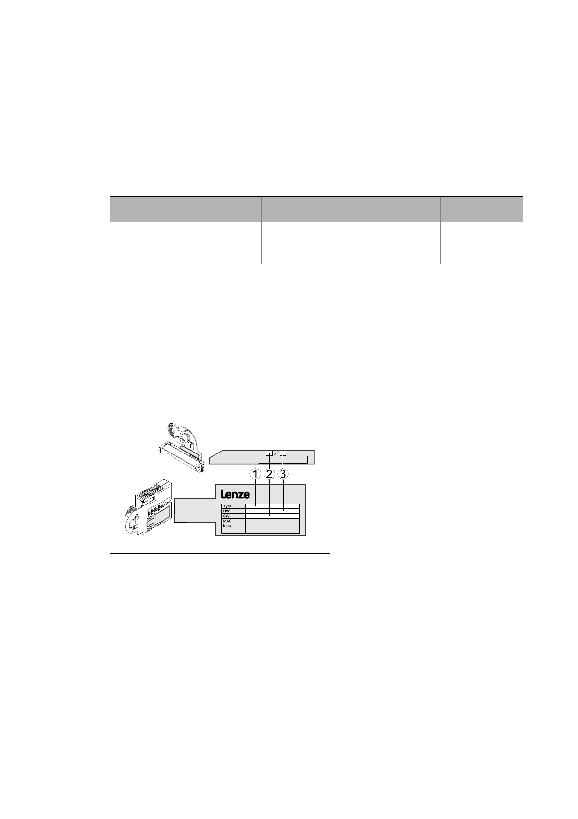
3.2 Identification
The type designation and hardware and software version of the communication module are
specified on the nameplate:
E94YCDN005
version
1 Type designation (type)
E94 Product series
AVersion
Y Module identification: extension module
C Module type: communication module
DN DeviceNet
2 Hardware version (HW)
3 Software version (SW)
From software
version
[3-1] Identification data
12
Lenze · E94AYCDN communication module (DeviceNet™) · Communication Manual · DMS 5.0 EN · 02/2014 · TD17
Page 13

3 Product description
3.3 Product features
_ _ _ _ _ _ _ _ _ _ _ _ _ _ _ _ _ _ _ _ _ _ _ _ _ _ _ _ _ _ _ _ _ _ _ _ _ _ _ _ _ _ _ _ _ _ _ _ _ _ _ _ _ _ _ _ _ _ _ _ _ _ _ _
3.3 Product features
• Interface module for connecting the DeviceNet communication system to the expansion slots
of Servo Drives 9400
• External voltage supply via the fieldbus
• "Group 2 Only Server (Device)" functionality
• Access to all Lenze parameters
• The MAC ID and baud rate (125, 250 and 500 kbps) can be set via the DIP switches on the front
• Can be easily connected due to pluggable terminal strip with double screw connection for thick/
thin cables
• Up to 32 I/O data words (16 bits/word) per direction can be exchanged.
• Support of the services:
• Poll Messages I/O
• Cyclic I/O
• Change of State (CoS) I/O
• Explicit messages
• Device Heartbeat Message
Lenze · E94AYCDN communication module (DeviceNet™) · Communication Manual · DMS 5.0 EN · 02/2014 · TD17 13
Page 14
3 Product description
3.4 Equipment
_ _ _ _ _ _ _ _ _ _ _ _ _ _ _ _ _ _ _ _ _ _ _ _ _ _ _ _ _ _ _ _ _ _ _ _ _ _ _ _ _ _ _ _ _ _ _ _ _ _ _ _ _ _ _ _ _ _ _ _ _ _ _ _
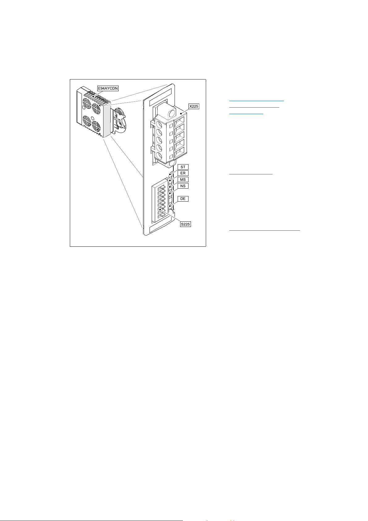
3.4 Equipment
X225 5-pole plug connector with screw connection
Wiring of the DeviceNet
DeviceNet connection
Voltage supply
ST
LED status displays for diagnostic purposes
ER
LED status displays
MS
NS
DE
( 29)
( 22)
( 24)
( 41)
S225 DIP switches for setting the station address
(MAC ID) and baud rate
Possible settings via DIP switch
( 32)
E94YCDN001B
[3-2] E94AYCDN communication module (DeviceNet)
14
Lenze · E94AYCDN communication module (DeviceNet™) · Communication Manual · DMS 5.0 EN · 02/2014 · TD17
Page 15

4Technical data
4.1 General data and operating conditions
_ _ _ _ _ _ _ _ _ _ _ _ _ _ _ _ _ _ _ _ _ _ _ _ _ _ _ _ _ _ _ _ _ _ _ _ _ _ _ _ _ _ _ _ _ _ _ _ _ _ _ _ _ _ _ _ _ _ _ _ _ _ _ _
4 Technical data
4.1 General data and operating conditions
Area Values
Order designation E94AYCDN
Communication profile DeviceNet
Interface 5-pole plug connector with screw connection
Communication medium EN 11898
Network topology Line terminated at both ends (R = 120 )
Number of nodes Max. 64
Max. cable length 500 m (dependent on the selected baud rate and the cable type used)
DeviceNet nodes Slave
Vendor ID 445 (0x1BD)
Device type 0 (generic device)
Product code 9400 (0x24B8)
Baud rate 125, 250, 500 kbps (adjustable via DIP switch)
Voltage supply External supply via the 5-pole plug connector
V+ : U = 24 V DC, I
V- : reference potential for external voltage supply
Conformities , approvals • CE
•UL
(see also hardware manual)
= 170 mA
max
Servo Drives 9400 hardware manual
Here you can find the ambient conditions and information on the electromagnetic
compatibility (EMC) which also apply to the communication module.
Lenze · E94AYCDN communication module (DeviceNet™) · Communication Manual · DMS 5.0 EN · 02/2014 · TD17 15
Page 16

4Technical data
4.2 Protective insulation
_ _ _ _ _ _ _ _ _ _ _ _ _ _ _ _ _ _ _ _ _ _ _ _ _ _ _ _ _ _ _ _ _ _ _ _ _ _ _ _ _ _ _ _ _ _ _ _ _ _ _ _ _ _ _ _ _ _ _ _ _ _ _ _
4.2 Protective insulation
Danger!
Dangerous voltage
If the Servo Drives 9400 are operated on a phase earthed mains with a rated mains
voltage 400 V, external measures need to be implemented in order to ensure
protection against accidental contact.
Possible consequences:
Death or severe injury
Protective measures:
If protection against accidental contact is required for the control terminals of the drive
and the connections of the plugged-in device modules, ...
• a double isolating distance must exist.
• the components to be connected must be provided with the second isolating
distance.
Note!
The available protective insulation in Servo Drives 9400 is implemented in accordance
with EN 61800-5-1.
16
Lenze · E94AYCDN communication module (DeviceNet™) · Communication Manual · DMS 5.0 EN · 02/2014 · TD17
Page 17
4Technical data
Ext. DC
I/O
X4
X6X6
X5
X7X7
X8X8
X3
X2
X1
X105X105
X106
X100
X107
MXI1
MXI2
Bus
Ext. DC
MSI
MMI
4.2 Protective insulation
_ _ _ _ _ _ _ _ _ _ _ _ _ _ _ _ _ _ _ _ _ _ _ _ _ _ _ _ _ _ _ _ _ _ _ _ _ _ _ _ _ _ _ _ _ _ _ _ _ _ _ _ _ _ _ _ _ _ _ _ _ _ _ _
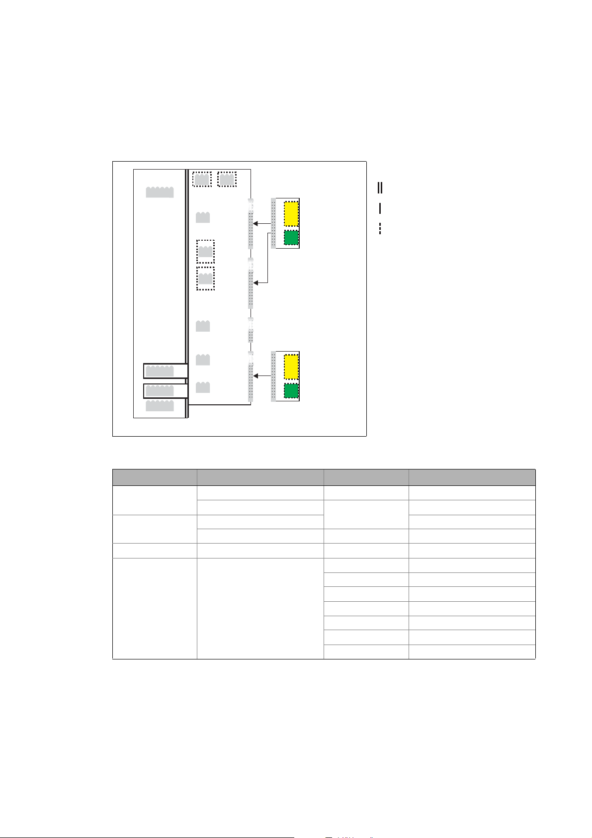
The following illustration ...
• shows the arrangement of the terminal strips and the separate potential areas of the drive.
• serves to determine the decisive protective insulation between two terminals located in
differently insulated separate potential areas.
Reinforced insulation
Basic insulation
Functional insulation
[4-1] Protective insulation to EN61800-5-1
Terminal strip Connection Terminal strip Connection
X100 L1, L2, L3 (only Single Drive) X1 CAN on board 9400
X105 U, V, W 24 V (ext.)
X106 Motor PTC X4 Digital outputs
X107 Control of the motor holding
E94YCXX007
+UG, -UG X2 Statebus
Rb1, Rb2 (only Single Drive) X3 Analog inputs/outputs
brake
MXI1, MXI2 Extension module
X5 Digital inputs
X6 Diagnostics
X7 Resolver
X8 Encoder
MMI Storage module
MSI Safety module
Lenze · E94AYCDN communication module (DeviceNet™) · Communication Manual · DMS 5.0 EN · 02/2014 · TD17 17
Page 18

4Technical data
4.3 Protocol data
_ _ _ _ _ _ _ _ _ _ _ _ _ _ _ _ _ _ _ _ _ _ _ _ _ _ _ _ _ _ _ _ _ _ _ _ _ _ _ _ _ _ _ _ _ _ _ _ _ _ _ _ _ _ _ _ _ _ _ _ _ _ _ _
Example
Which type of protective insulation is there between the bus terminal of the device module on slot
MXI1 or MXI2 and the mains terminal X100?
The separate potential area with the better protective insulation is decisive.
• The separate potential area of the bus terminal of the device module has a "functional
insulation".
• The separate potential area of the mains terminal has a "reinforced insulation".
Result: The insulation between mains terminal X100 and the bus terminal is a "reinforced
insulation".
4.3 Protocol data
Area Values
Process data words 1 ... 32 words (16 bits/word)
Supported services • Reset
• Get_Attribute_Single
• Set_Attribute_Single
• Allocate_Master/Slave_Connection_Set
• Release_Group_2_Identifier_Set
4.4 Communication time
The communication time is the time between the start of a request and the arrival of the
corresponding response.
The communication times in an DeviceNet network depend on the ...
• Processing time inside the drive;
• telegram runtime (baud rate / telegram length).
Processing time inside the drive
There are no interconnections between parameter data and process data.
Data Processing time
Process data Approx. 2 ms + 1 ms tolerance + runtime of the technology applications used
Parameter data Approx. 30 ms + a tolerance of 20 ms (typically)
For some codes the processing time can be longer (see reference manual/
»Engineer« online help for the Servo Drive 9400).
18
Lenze · E94AYCDN communication module (DeviceNet™) · Communication Manual · DMS 5.0 EN · 02/2014 · TD17
Page 19
4Technical data
4.5 Dimensions
_ _ _ _ _ _ _ _ _ _ _ _ _ _ _ _ _ _ _ _ _ _ _ _ _ _ _ _ _ _ _ _ _ _ _ _ _ _ _ _ _ _ _ _ _ _ _ _ _ _ _ _ _ _ _ _ _ _ _ _ _ _ _ _
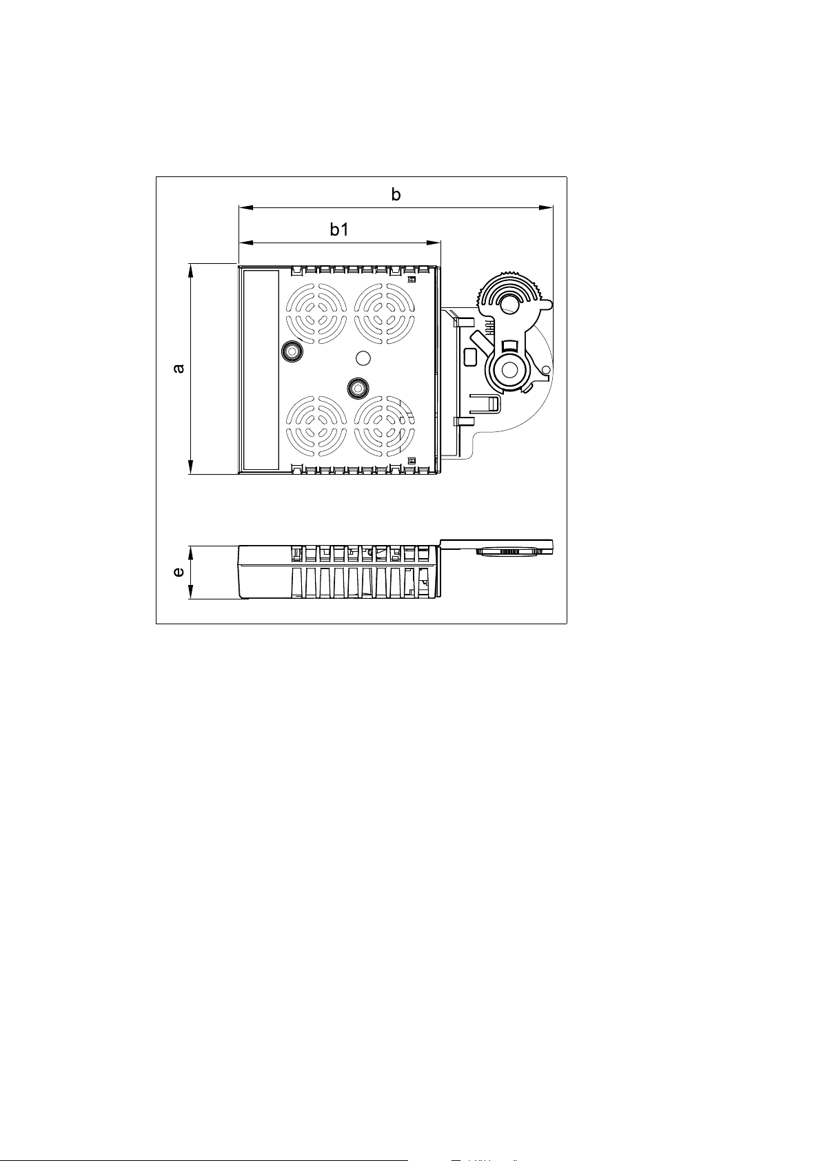
4.5 Dimensions
a 89 mm
b 134 mm
b1 87 mm
e 23 mm
[4-2] Dimensions
E94YCXX005
Lenze · E94AYCDN communication module (DeviceNet™) · Communication Manual · DMS 5.0 EN · 02/2014 · TD17 19
Page 20

5 Installation
_ _ _ _ _ _ _ _ _ _ _ _ _ _ _ _ _ _ _ _ _ _ _ _ _ _ _ _ _ _ _ _ _ _ _ _ _ _ _ _ _ _ _ _ _ _ _ _ _ _ _ _ _ _ _ _ _ _ _ _ _ _ _ _
5 Installation
Stop!
Electrostatic discharge
Electronic components within the communication module can be damaged or destroyed
by electrostatic discharge.
Possible consequences
• The communication module is defective.
• Fieldbus communication is not possible or faulty.
Protective measures
Free yourself from any electrostatic charge before you touch the module.
20 Lenze · E94AYCDN communication module (DeviceNet™) · Communication Manual · DMS 5.0 EN · 02/2014 · TD17
Page 21
5 Installation
5.1 Mechanical installation
_ _ _ _ _ _ _ _ _ _ _ _ _ _ _ _ _ _ _ _ _ _ _ _ _ _ _ _ _ _ _ _ _ _ _ _ _ _ _ _ _ _ _ _ _ _ _ _ _ _ _ _ _ _ _ _ _ _ _ _ _ _ _ _
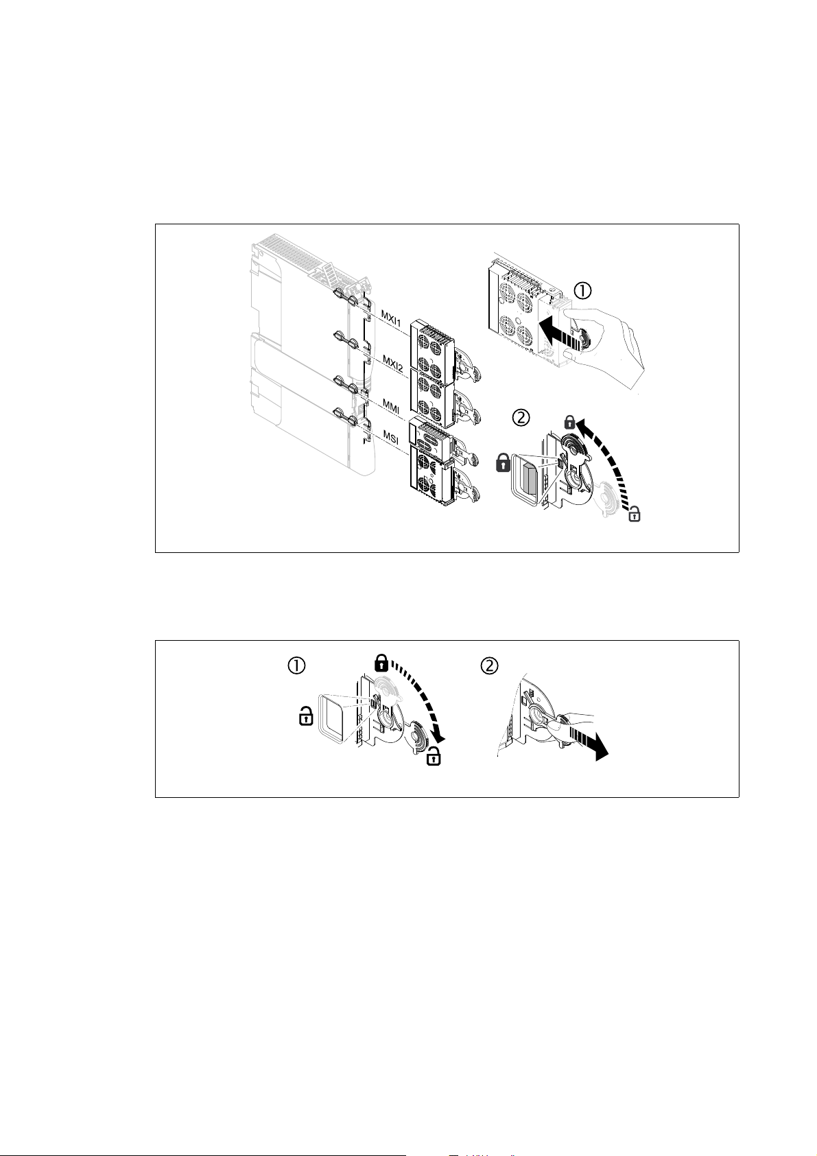
5.1 Mechanical installation
5.1.1 Mounting
[5-1] Mounting
5.1.2 Dismounting
[5-2] Dismounting
E94YCXX001G
E94AYCXX001H
Lenze · E94AYCDN communication module (DeviceNet™) · Communication Manual · DMS 5.0 EN · 02/2014 · TD17 21
Page 22

5 Installation
5.2 Electrical installation
_ _ _ _ _ _ _ _ _ _ _ _ _ _ _ _ _ _ _ _ _ _ _ _ _ _ _ _ _ _ _ _ _ _ _ _ _ _ _ _ _ _ _ _ _ _ _ _ _ _ _ _ _ _ _ _ _ _ _ _ _ _ _ _
5.2 Electrical installation
Documentation relating to the standard device, host (PLC, scanner), system/machine
Observe the notes and wiring instructions contained in this documentation.
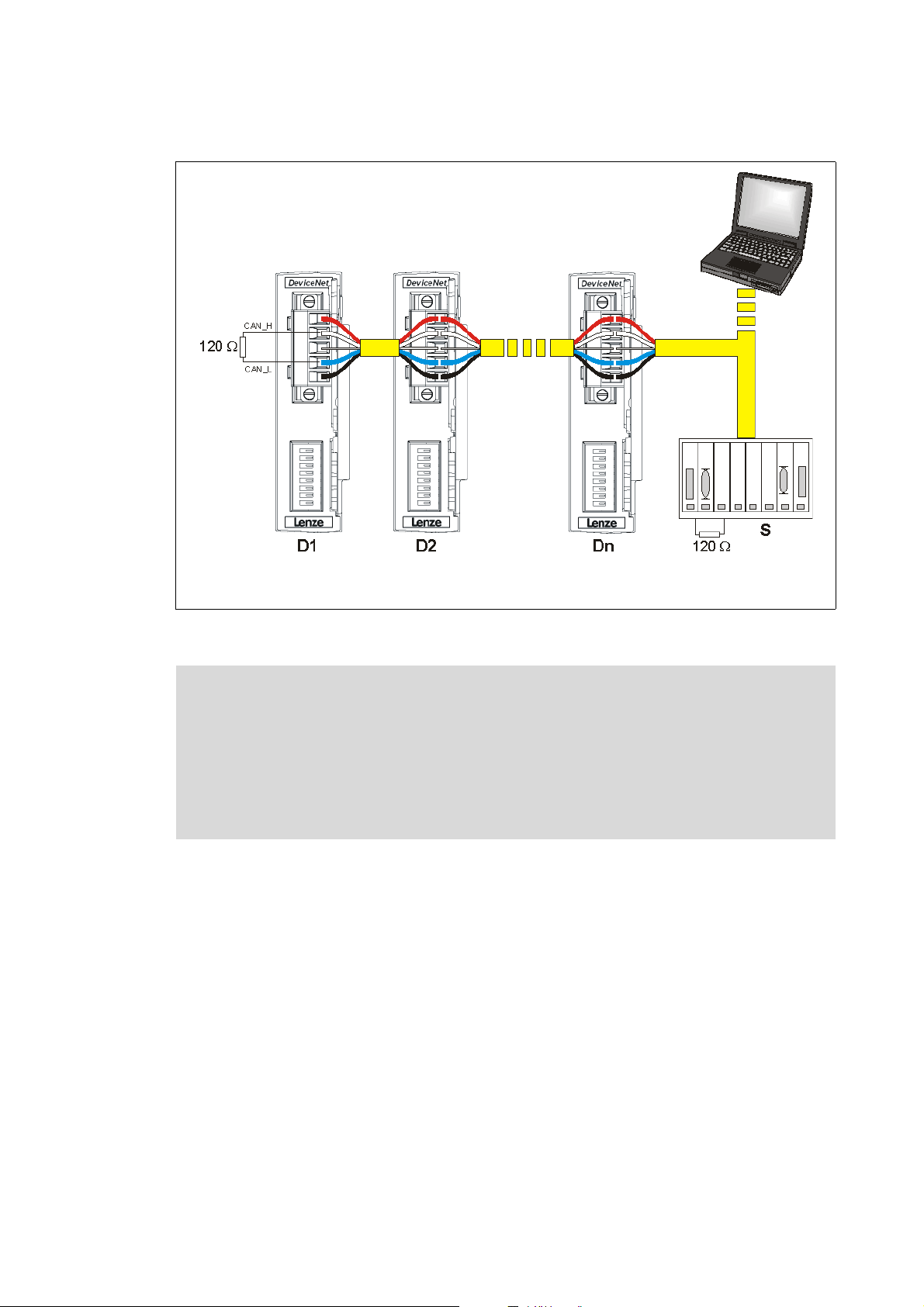
5.2.1 Wiring of the DeviceNet
For communication with the scanner and all further components, Servo Drives 9400 have to be
assembled with communication modules.
A DeviceNet line can have a maximum number of 64 nodes. The nodes include ...
• the scanner;
• the connected drives (devices);
• all other components which take part in communication.
For integrating the communication modules in the DeviceNet line, a PC/laptop with installed
configuration software (e. g. »RSNetWorx«) is required. The PC/laptop solely serves to the
configuration and diagnostics and therefore is not a DeviceNet node.
22
Lenze · E94AYCDN communication module (DeviceNet™) · Communication Manual · DMS 5.0 EN · 02/2014 · TD17
Page 23
5 Installation
5.2 Electrical installation
_ _ _ _ _ _ _ _ _ _ _ _ _ _ _ _ _ _ _ _ _ _ _ _ _ _ _ _ _ _ _ _ _ _ _ _ _ _ _ _ _ _ _ _ _ _ _ _ _ _ _ _ _ _ _ _ _ _ _ _ _ _ _ _
D1 ... n: Devices 1 ... n
S: scanner (e.g. PLC, IPC)
[5-3] DeviceNet line
Note!
• Connect a bus terminating resistor of 120 each to the first and the last node of the
• Connect the shield at the voltage supply together with the "V-" connection to GND
• Connect the shield of the DeviceNet cable for each node only to the SHIELD
E94YCDN008
DeviceNet line.
once. For this purpose, use the centre point of the DeviceNet line, if possible.
connection of the plug connector.
Lenze · E94AYCDN communication module (DeviceNet™) · Communication Manual · DMS 5.0 EN · 02/2014 · TD17 23
Page 24
5 Installation
Vcc
Vcc
V+
CAN_H
SHIELD
CAN_L
V-
7
6
2
8
5
3
1
4
5.2 Electrical installation
_ _ _ _ _ _ _ _ _ _ _ _ _ _ _ _ _ _ _ _ _ _ _ _ _ _ _ _ _ _ _ _ _ _ _ _ _ _ _ _ _ _ _ _ _ _ _ _ _ _ _ _ _ _ _ _ _ _ _ _ _ _ _ _
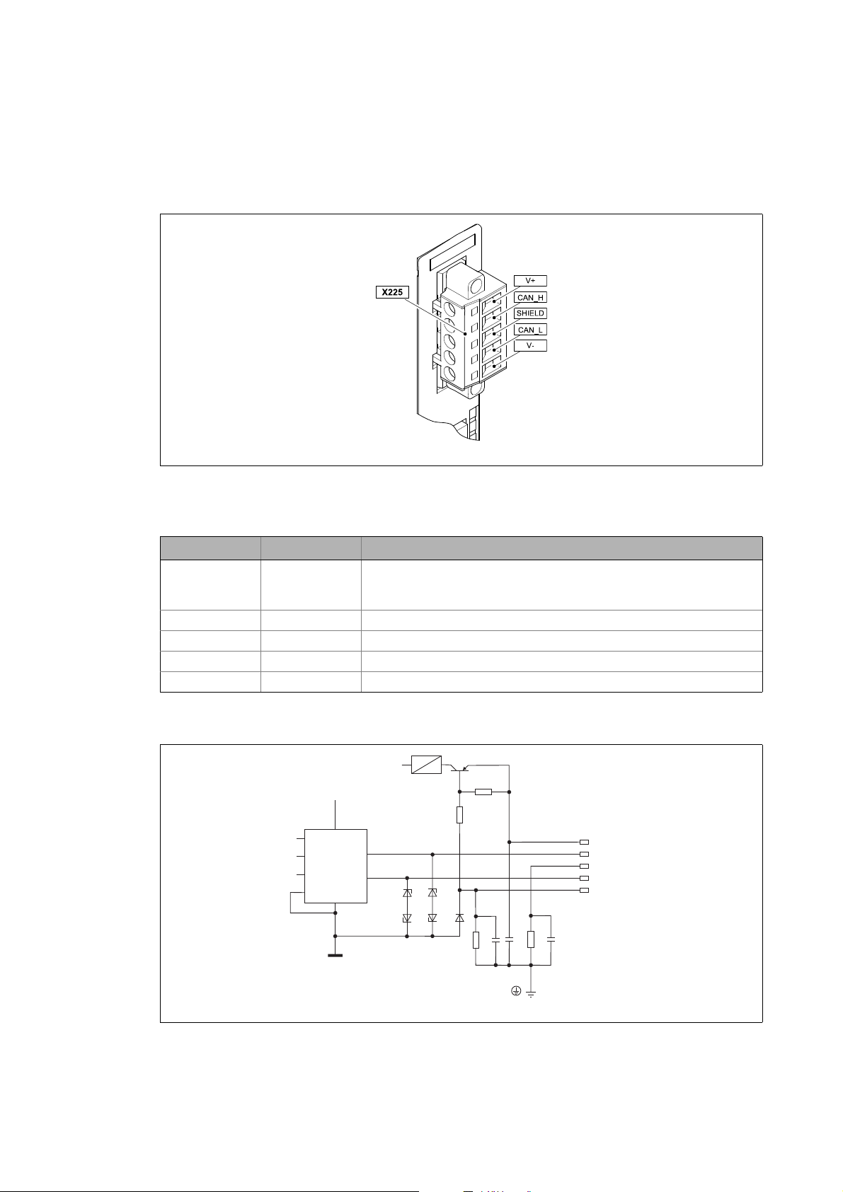
5.2.2 DeviceNet connection
The bus connection of the communication module is effected via the 5-pole plug connector with
double screw connection (X225).
E94YCDN001C
[5-4] 5-pole plug connector with double screw connection
Plug connector assignment (X225)
Terminal Cable colour Description
V+ red External voltage supply
• U = 24 V DC
•I
= 170 mA
CAN_H White Data line / input for bus terminating resistor (120 )
SHIELD Shielding
CAN_L Blue Data line / input for bus terminating resistor (120 )
V- Black Reference potential for external voltage supply
max
Internal wiring of the plug connector (X225)
[5-5] Internal wiring X225
24
Lenze · E94AYCDN communication module (DeviceNet™) · Communication Manual · DMS 5.0 EN · 02/2014 · TD17
E94YCDN006
Page 25

5 Installation
5.2 Electrical installation
_ _ _ _ _ _ _ _ _ _ _ _ _ _ _ _ _ _ _ _ _ _ _ _ _ _ _ _ _ _ _ _ _ _ _ _ _ _ _ _ _ _ _ _ _ _ _ _ _ _ _ _ _ _ _ _ _ _ _ _ _ _ _ _
5.2.3 Specification of the bus cable
The nodes of the bus system must be wired with a fieldbus cable - a DeviceNet thick or thin cable according to the DeviceNet specifications (DeviceNet Adaption of CIP, Edition 1.1, Volume 3).
DeviceNet thick and thin cables for instance are manufactured by Belden Inc., Lapp, C&M Corp., and
Madison Cable Corp.
Note!
If you do not wish to use a thick or thin cable, the cable used must meet the requirements
given in the DeviceNet specifications.
A cable that does not meet the requirements given in the DeviceNet specifications must
not be used!
Properties of the thick cable according to the DeviceNet specifications
General properties
Arrangement Two shielded, symmetrical cables, common axis with drain wire in the centre
Overall shielding Coverage: 65 percent
AWG 36, or at least 0.12 mm tinned copper braid (individually tinned)
Drain wire At least copper 18; at least 19 cores (individually tinned)
Outer diameter 10.41 mm (min.) ... 12.45 mm (max.)
Roundness A radius deviation must not exceed 15 percent of one half of the outer
Cable sheath labelling Vendor name, part number and additional labelling
DC resistor specification (braid,
wrapping, discharge)
Certifications (U.S. and Canada) NEC (UL), CL2/CL3 (minimum)
Bend radius 20 x the diameter (installation) / 7 x the diameter (fixed)
Ambient temperature during
operation
Storage temperature -40 ... +85°C
Pull tension max. 845.5 N
diameter
5.74 /km (nominally up to 20°C)
-20 ... +60°C at 8 A; linear current derating to zero at 80°C
Lenze · E94AYCDN communication module (DeviceNet™) · Communication Manual · DMS 5.0 EN · 02/2014 · TD17 25
Page 26

5 Installation
5.2 Electrical installation
_ _ _ _ _ _ _ _ _ _ _ _ _ _ _ _ _ _ _ _ _ _ _ _ _ _ _ _ _ _ _ _ _ _ _ _ _ _ _ _ _ _ _ _ _ _ _ _ _ _ _ _ _ _ _ _ _ _ _ _ _ _ _ _
Data line properties
Wire pair At least copper 18; at least 19 cores (individually tinned)
Insulation diameter 3.81 mm (nominal)
Colours Light blue / white
Pair windings / m Approx. 10
Shielding per wire pair 2000/1000, Al/Mylar, Al side outside, w/shorting fold (pull tension)
Impedance 120 +/- 10 % (at 1 MHz)
Capacity between conductors 39.37 pF/m at 1 kHz (nominal)
Capacity between a conductor and
another which is connected to the
shield
Capacitive unbalance 3937 pF/km at 1 kHz (nominal)
DC resistor specification at 20°C max. 22.64 /km
Damping max. 0.43 dB/100 m at 125 kHz
78.74 pF/m at 1 kHz (nominal)
max. 0.82 dB/100 m at 500 kHz
max. 1.31 dB/100 m at 1 MHz
Voltage conduction properties
Wire pair At least copper 15; at least 19 cores (individually tinned)
Insulation diameter 2.49 mm (nominal)
Colours Red / black
Pair windings / m Approx. 10
Shielding per wire pair 1000/1000, Al/Mylar, Al side outside, w/shorting fold (pull tension)
DC resistor specification at 20°C max. 11.81 /km
26
Lenze · E94AYCDN communication module (DeviceNet™) · Communication Manual · DMS 5.0 EN · 02/2014 · TD17
Page 27

5 Installation
5.2 Electrical installation
_ _ _ _ _ _ _ _ _ _ _ _ _ _ _ _ _ _ _ _ _ _ _ _ _ _ _ _ _ _ _ _ _ _ _ _ _ _ _ _ _ _ _ _ _ _ _ _ _ _ _ _ _ _ _ _ _ _ _ _ _ _ _ _
Properties of the thin cable according to the DeviceNet specifications
General properties
Arrangement Two shielded, symmetrical cables, common axis with drain wire in the centre
Overall shielding Coverage: 65 percent
AWG 36, or at least 0.12 mm tinned copper braid (individually tinned)
Drain wire At least copper 22; at least 19 cores (individually tinned)
Outer diameter 6.096 mm (minimum) ... 7.112 mm (maximum)
Roundness A radius deviation must not exceed 20 percent of one half of the outer
Cable sheath labelling Vendor name, part number and additional labelling
DC resistor specification (braid,
wrapping, discharge)
Certifications (U.S. and Canada) NEC (UL), CL2 (minimum)
Bend radius 20 x the diameter (installation) / 7 x the diameter (fixed)
Ambient temperature during
operation
Storage temperature -40 ... +85°C
Pull tension 289.23 N (maximum)
diameter
10.5 /km (nominally at 20°C)
-20 ... +70°C at 1.5 A; linear current derating to zero at 80°C
Data line properties
Insulation diameter 1.96 mm (nominal)
Wire pair At least copper 24; at least 19 cores (individually tinned)
Colours Light blue / white
Pair windings / m Approx. 16
Shielding per wire pair 1000/1000, Al/Mylar, Al side outside, w/shorting fold (pull tension)
Impedance 120 +/- 10 % (at 1 MHz)
Runtime 4.46 ns/m (maximum)
Capacity between conductors 39.37 pF/m at 1 kHz (nominal)
Capacity between a conductor and
another which is connected to the
shield
Capacitive unbalance Max. 3.94 pF/km at 1 kHz
DC resistor specification at 20°C max. 91.86 /km
Damping max. 0.95 dB/100 m at 125 kHz
Voltage conduction properties
Wire pair At least copper 22; at least 19 cores (individually tinned)
Insulation diameter 1.4 mm (nominal)
Colours Red / black
Pair windings / m Approx. 16
Shielding per wire pair 1000/1000, Al/Mylar, Al side outside, w/shorting fold (pull tension)
DC resistor specification at 20°C 57.41 /km (maximum)
78.74 pF/m at 1 kHz (nominal)
1.64 dB/100 m at 500 kHz (maximum)
2.30 dB/100 m at 1 MHz (maximum)
Lenze · E94AYCDN communication module (DeviceNet™) · Communication Manual · DMS 5.0 EN · 02/2014 · TD17 27
Page 28

5 Installation
5.2 Electrical installation
_ _ _ _ _ _ _ _ _ _ _ _ _ _ _ _ _ _ _ _ _ _ _ _ _ _ _ _ _ _ _ _ _ _ _ _ _ _ _ _ _ _ _ _ _ _ _ _ _ _ _ _ _ _ _ _ _ _ _ _ _ _ _ _
5.2.4 Bus cable length
The following bus cable lengths are possible depending on the baud rate and the cable type used
(thick cable/thin cable):
Baud rate [kbps] Bus cable lengths [m]
Thick cable Thin cable
125 500
250 250 100
500 100
If both thick and thin cables are used, the maximum cable lengths depending on the baud rate can
be determined as follows:
Baud rate [kbps] Max. bus cable length
125 500 m = L
250 250 m = L
500 100 m = L
L
: Length of the thick cable
thick
L
: Length of the thin cable
thin
thick
thick
thick
+ 5 L
+ 2.5 L
+ L
thin
thin
thin
Note!
Select the baud rate which depends on the data volume, cycle time, and number of
nodes just high enough to suit your application.
28
Lenze · E94AYCDN communication module (DeviceNet™) · Communication Manual · DMS 5.0 EN · 02/2014 · TD17
Page 29

5 Installation
5.2 Electrical installation
_ _ _ _ _ _ _ _ _ _ _ _ _ _ _ _ _ _ _ _ _ _ _ _ _ _ _ _ _ _ _ _ _ _ _ _ _ _ _ _ _ _ _ _ _ _ _ _ _ _ _ _ _ _ _ _ _ _ _ _ _ _ _ _
5.2.5 Voltage supply
The communication module is externally supplied with voltage at the 5-pole plug connector (X225)
via the DeviceNet line.
Note!
Use a safely separated power supply unit (SELV/PELV) in accordance with EN 61800-5-1.
• The communication module always requires an external voltage supply.
• Communication with a standard device that is separated from the mains is not possible.
Terminal data (X225)
Terminal Cable colour Description
V+ red External voltage supply
• U = 24 V DC
•I
= 170 mA
max
V- Black Reference potential for external voltage supply
Area Values
Electrical connection Plug connector with double screw connection
Possible connections rigid:
2
2.5 mm
flexible:
without wire end ferrule
2.5 mm
with wire end ferrule, without plastic sleeve
2.5 mm
with wire end ferrule, with plastic sleeve
2.5 mm
Tightening torque 0.5 ... 0.6 Nm (4.4 ... 5.3 lb-in)
Bare end 7 mm
(AWG 14)
2
(AWG 14)
2
(AWG 14)
2
(AWG 14)
Lenze · E94AYCDN communication module (DeviceNet™) · Communication Manual · DMS 5.0 EN · 02/2014 · TD17 29
Page 30

6 Commissioning
6.1 Before initial switch-on
_ _ _ _ _ _ _ _ _ _ _ _ _ _ _ _ _ _ _ _ _ _ _ _ _ _ _ _ _ _ _ _ _ _ _ _ _ _ _ _ _ _ _ _ _ _ _ _ _ _ _ _ _ _ _ _ _ _ _ _ _ _ _ _
6 Commissioning
During commissioning, system-related data such as motor parameters, operating parameters,
responses, and parameters for fieldbus communication are defined in the drive. For Lenze devices,
this is done by means of codes.
The codes of the drive and communication are saved non-volatilely as a data set in the memory
module.
In addition to codes for the configuration, there are codes for diagnosing and monitoring the nodes.
Note!
When parameterising the communication module, please note that the code number
depends on the slot of the standard device which the communication module is plugged
into.
The first two digits of the code number specify the slot:
•C13nnn for slot MXI1
Parameters of the communication module for the MXI1 slot
•C14nnn for slot MXI2
Parameters of the communication module for the MXI2 slot
Furthermore set Communication-relevant parameters of the standard device ( 48).
( 50)
( 57)
6.1 Before initial switch-on
Stop!
Before switching on the standard device with the communication module for the first
time, check ...
• the entire cabling for completeness, short circuit and earth fault.
• whether the bus system is terminated at the first and last physical node by means of
a bus terminating resistor (120 ).
30
Lenze · E94AYCDN communication module (DeviceNet™) · Communication Manual · DMS 5.0 EN · 02/2014 · TD17
Page 31

6 Commissioning
6.2 Configuring the host (PLC, scanner)
_ _ _ _ _ _ _ _ _ _ _ _ _ _ _ _ _ _ _ _ _ _ _ _ _ _ _ _ _ _ _ _ _ _ _ _ _ _ _ _ _ _ _ _ _ _ _ _ _ _ _ _ _ _ _ _ _ _ _ _ _ _ _ _
6.2 Configuring the host (PLC, scanner)
For communication with the communication module, the host (PLC, scanner) must be configured
first.
Configuration for device control
For the configuration of DeviceNet, the EDS file of the communication module has to be imported
via the configuration software (e.g. »RSNetWorx« Rockwell software).
The EDS file E94AYCDN_Vxxx.eds required for configuration can be found in the download area at:
www.lenze.com
Specifying the user data length
Note!
The direction of the flow of information must be observed!
• Consumed I/O data: process data from the scanner to the drive (device)
• Produced I/O data: process data from the drive (device) to the scanner
The Servo Drives 9400 support the configuration of max. 32 process data words (max. 64 bytes) per
direction.
The user data length for consumed and produced I/O data can vary.
The user data lengths (number of process data) must be set and stored via the »Engineer« or the
scanner (Lenze Class (0x66 / 102)
User data length for consumed I/O data User data length for produced I/O data
Setting via the »Engineer« using C13883
The length of the ports mapped into the receipt PDO
results from the Configuring I/O data (PDO mapping)
( 36) and is displayed in C13854/1
length does not correspond to the user length data of the
consumed I/O data from C13883
DeviceNet: Consumed I/O data length is contradictory
[0x00C88211] ( 46) error message will be generated
and entered as a warning in the logbook of the standard
device when the I/O connection is established.
( 75)):
/ C14883 Setting via the »Engineer« using C13884 / C14884
The length of the ports mapped into the transmission
/ C14854/1. If this
/ C14883, the
PDO results from the Configuring I/O data (PDO
mapping) ( 36) and is displayed in C13855/1 /
C14855/1
length data of the produced I/O data from C13884
C14884
contradictory [0x00C88212] ( 46) error message will
be generated and entered as a warning in the logbook of
the standard device when the I/O connection is
established.
. If this length does not correspond to the user
, the DeviceNet: Produced I/O data length is
/
Lenze · E94AYCDN communication module (DeviceNet™) · Communication Manual · DMS 5.0 EN · 02/2014 · TD17 31
Page 32

6 Commissioning
6.3 Possible settings via DIP switch
_ _ _ _ _ _ _ _ _ _ _ _ _ _ _ _ _ _ _ _ _ _ _ _ _ _ _ _ _ _ _ _ _ _ _ _ _ _ _ _ _ _ _ _ _ _ _ _ _ _ _ _ _ _ _ _ _ _ _ _ _ _ _ _
6.3 Possible settings via DIP switch
The following can be set via the DIP switch on the front:
• Station address
Range: MAC ID
Switches: 1 ... 32
•Baud rate
Range: Baud
Switches: 1 and 2
Lenze setting: all switches OFF
E94YCPM001D
[6-1] DIP switch
6.3.1 Setting the station address (MAC ID)
• The station address is set via the switches 1 ... 32 (MAC ID).
• The housing labelling corresponds to the binary values of the individual switches for
determining the station address.
• Valid address range: 0 … 63
• The current address setting is displayed in C13864
Example: Setting of station address 23
Switch (MAC ID) 32 16 8 4 2 1
Switch status OFF ON OFF ON ON ON
Value 0
Station address = sum of the values = 16 + 4 + 2 + 1 = 23
DIP switch positions for setting the station address
6.3.2 Setting the baud rate
The baud rate is set via the switches 1 and 2 (Baud).
Switch (Baud) Baud rate
2 1
OFF OFF 125 kbps
OFF ON 250 kbps
ON OFF 500 kbps
ON ON No function / switch status is not supported.
/ C14864.
16 0 4 2 1
( 83)
32
The current baud rate setting is displayed in C13863
Lenze · E94AYCDN communication module (DeviceNet™) · Communication Manual · DMS 5.0 EN · 02/2014 · TD17
/ C14863.
Page 33

6 Commissioning
6.4 Initial switch-on
_ _ _ _ _ _ _ _ _ _ _ _ _ _ _ _ _ _ _ _ _ _ _ _ _ _ _ _ _ _ _ _ _ _ _ _ _ _ _ _ _ _ _ _ _ _ _ _ _ _ _ _ _ _ _ _ _ _ _ _ _ _ _ _
6.4 Initial switch-on
Documentation for the standard device
Observe the safety instructions and information on residual hazards contained in this
documentation.
Note!
Establishing communication
When the communication module is externally supplied, the standard device must also
be switched on to establish communication.
After communication has been established, communication of the externally supplied
module is independent of the switching status of the standard device.
Activating changed setting
In order to activate any changed settings, ...
• execute the device command "11: Save start parameter" via the standard device code
C00002 and ...
• then execute a "reset node" of the node or switch off and then on again the voltage
supply of the communication module.
Protection against uncontrolled restart
Following a fault (short-term mains failure, for example), it is sometimes undesirable or
even impermissible for the drive to restart.
In the Lenze setting of Servo Drives 9400, the restart protection is activated.
The restart behaviour of the drive can be set via C00142 ("auto restart after mains
connection"):
C00142 = "0: Inhibited" (Lenze setting)
• The drive remains inhibited (even if the fault is no longer active).
• A controlled restart of the drive is effected by explicit drive enable: LOW/HIGH edge
at the digital input X5/RFR.
C00142 = 1: Enabled
• An uncontrolled restart of the drive is possible.
Lenze · E94AYCDN communication module (DeviceNet™) · Communication Manual · DMS 5.0 EN · 02/2014 · TD17 33
Page 34

7 Data transfer
7.1 Communication channels
_ _ _ _ _ _ _ _ _ _ _ _ _ _ _ _ _ _ _ _ _ _ _ _ _ _ _ _ _ _ _ _ _ _ _ _ _ _ _ _ _ _ _ _ _ _ _ _ _ _ _ _ _ _ _ _ _ _ _ _ _ _ _ _
7 Data transfer
7.1 Communication channels
The Telegram types ( 35) are assigned to the communication channels according to their time-
critical behaviour:
The process data channel transmits I/O data.
• The drive is controlled by means of the I/O data.
• The host (PLC, scanner) can directly access the I/O data. In the PLC, the data are, for instance,
directly stored in the I/O area.
• I/O data are not stored in the drive (device).
• I/O data are transmitted cyclically between the host and the drives (permanent exchange of
current input and output data).
The parameter data channel transmits explicit messages.
• The parameter data channel provides access to all Lenze codes.
• Parameter changes must be stored via code C00002 code of the Servo Drives 9400.
34
Lenze · E94AYCDN communication module (DeviceNet™) · Communication Manual · DMS 5.0 EN · 02/2014 · TD17
Page 35

7 Data transfer
7.2 Telegram types
_ _ _ _ _ _ _ _ _ _ _ _ _ _ _ _ _ _ _ _ _ _ _ _ _ _ _ _ _ _ _ _ _ _ _ _ _ _ _ _ _ _ _ _ _ _ _ _ _ _ _ _ _ _ _ _ _ _ _ _ _ _ _ _
7.2 Telegram types
The "I/O data" (process data) and "Explicit Messages (parameter data) telegram types are
transmitted between the host (PLC, scanner) and the drives (devices).
7.2.1 I/O data (process data)
I/O data are transmitted or received according to the producer/consumer principle. There is one
transmitter and no receiver or an optional number of receivers.
• Consumed I/O data: process data from the scanner to the drive (device)
• Produced I/O data: process data from the drive (device) to the scanner
Assembly Class (0x04 / 4)
The following transmission modes are supported:
• Poll I/O data:
The polling command which is transmitted by the scanner includes output data for the device.
The device then transmits its input data to the scanner. The polling response can also be
regarded as an acknowledgement.
• Cyclic I/O data:
The scanner and the device use cyclic I/O data to generate their data independently of each
other, which are then transmitted depending on a timer. The value of the timer must be set by
the user.
( 69)
• Change of State (CoS) I/O data:
This I/O data type is a special case of cyclic I/O data. CoS nodes always transmit their data if the
state of the data changes.
Connection Class (0x05 / 5)
( 70)
7.2.2 Explicit messages (parameter data)
Explicit messages serve to configure and parameterise the individual devices of the DeviceNet.
Two nodes have a client/server relationship:
The client transmits a job (request). The server receives this job and tries to accomplish it. The server
then transmits the requested data (positive response) or an error message (negative response).
Connection Class (0x05 / 5)
( 70)
7.2.3 Device Heartbeat Message
Within a configurable time interval, the device transmits its own device state to the bus via the
Device Heartbeat Message. The Device Heartbeat Message can be configured via the DeviceNet
object Identity Class (0x01 / 1)
Adjustable time interval: 1 ... 255 ms
( 67) - instance 1, attribute 10.
Lenze · E94AYCDN communication module (DeviceNet™) · Communication Manual · DMS 5.0 EN · 02/2014 · TD17 35
Page 36

7 Data transfer
7.3 Configuring I/O data (PDO mapping)
_ _ _ _ _ _ _ _ _ _ _ _ _ _ _ _ _ _ _ _ _ _ _ _ _ _ _ _ _ _ _ _ _ _ _ _ _ _ _ _ _ _ _ _ _ _ _ _ _ _ _ _ _ _ _ _ _ _ _ _ _ _ _ _
7.3 Configuring I/O data (PDO mapping)
For Servo Drives 9400 HighLine, the I/O data can be arranged individually (mapping). For this
purpose, the »Engineer« provides a port configurator.
The following example describes the steps required for the Servo Drive 9400 HighLine to implement
I/O data communication with a host (PLC, scanner) during which a control/status word and a 32-bit
setpoint/actual value is exchanged, respectively.
How to set the PDO mapping with the »Engineer«:
1. The I/O data mapping to the port variables is executed in the »Engineer« under the Process
data objects tab of the corresponding fieldbus communication module:
2. Select the PDO_RX0 receive object:
36
Lenze · E94AYCDN communication module (DeviceNet™) · Communication Manual · DMS 5.0 EN · 02/2014 · TD17
Page 37

7 Data transfer
7.3 Configuring I/O data (PDO mapping)
_ _ _ _ _ _ _ _ _ _ _ _ _ _ _ _ _ _ _ _ _ _ _ _ _ _ _ _ _ _ _ _ _ _ _ _ _ _ _ _ _ _ _ _ _ _ _ _ _ _ _ _ _ _ _ _ _ _ _ _ _ _ _ _
3. Click the Edit PDO button. The selection window Process data object structure: PDO_RX0
will open:
Here you can transfer the individual ports from the Port Selection list to the "PDO_RX0"
receive PDO by clicking the >> button.
The Up and Down buttons serve to shift the sequence of the ports within the PDOs.
Note
Port mapping is no configuration that can be carried out online for the Servo Drive 9400
HighLine. The »Engineer« project must always be updated and the application must
always be downloaded afterwards.
Lenze · E94AYCDN communication module (DeviceNet™) · Communication Manual · DMS 5.0 EN · 02/2014 · TD17 37
Page 38

7 Data transfer
7.3 Configuring I/O data (PDO mapping)
_ _ _ _ _ _ _ _ _ _ _ _ _ _ _ _ _ _ _ _ _ _ _ _ _ _ _ _ _ _ _ _ _ _ _ _ _ _ _ _ _ _ _ _ _ _ _ _ _ _ _ _ _ _ _ _ _ _ _ _ _ _ _ _
The following example shows the mapping of the ports "LPortControl1" and "Lport32In1"
into the reception PDO "PDO_RX0" and the mapping of the ports "LPortStatus1" and
"LPort32Out1" into the transmission PDO "PDO_TX0":
4. Confirm the selection with OK.
5. Repeat the steps 2. to 4. for the transmit object PDO_TX0.
6. Then link the ports to application signals in the technology application selected.
If the »FB Editor« is not enabled, this action can be carried out in the multiplexer codes
(> C03000).
If the »FB-Editor« is enabled, the multiplexer codes (> C03000) are no longer available. In
this case, the interconnection must be executed directly in the »FB Editor«.
38
Lenze · E94AYCDN communication module (DeviceNet™) · Communication Manual · DMS 5.0 EN · 02/2014 · TD17
Page 39

8 Monitoring
8.1 Interruption of the DeviceNet communication
_ _ _ _ _ _ _ _ _ _ _ _ _ _ _ _ _ _ _ _ _ _ _ _ _ _ _ _ _ _ _ _ _ _ _ _ _ _ _ _ _ _ _ _ _ _ _ _ _ _ _ _ _ _ _ _ _ _ _ _ _ _ _ _
8 Monitoring
8.1 Interruption of the DeviceNet communication
An interruption of the DeviceNet communication, e.g. by a cable break or a failure of the host (PLC,
scanner), is detected by the communication module.
Responses to communication faults can be set in the DeviceNet object Lenze Class (0x65 / 101)
( 74) or under the Monitoring tab:
Settings Description
Idle Mode The scanner does not transmit any I/O data if it is in idle state.
If the device (communication module) is in the idle state, the response
parameterised here (C13880/1
I/O connection timeout The data transmission of the poll or CoS/Cyclic I/O connections can be
Communication error The device (communication module) automatically recognises
monitored by timeouts.
The timeout values are configured within the Connection Class (0x05 / 5)
( 70) - instance 2 (poll I/O) or instance 4 (CoS/Cyclic I/O), attribute 9.
After the monitoring time has elapsed, the response parameterised here
(C13880/2
communication faults.
If a communication fault is active, the response parameterised here
(C13880/3
/ C14880/2) is activated in the drive.
/ C14880/3) is activated in the drive.
/ C14880/1) is activated in the drive.
Lenze · E94AYCDN communication module (DeviceNet™) · Communication Manual · DMS 5.0 EN · 02/2014 · TD17 39
Page 40

8 Monitoring
8.2 Fault with regard to internal communication
_ _ _ _ _ _ _ _ _ _ _ _ _ _ _ _ _ _ _ _ _ _ _ _ _ _ _ _ _ _ _ _ _ _ _ _ _ _ _ _ _ _ _ _ _ _ _ _ _ _ _ _ _ _ _ _ _ _ _ _ _ _ _ _
8.2 Fault with regard to internal communication
The response to a communication error between the communication module and the standard
device can be set via these codes:
• C01501
• C01502
(module in slot MXI1)
(module in slot MXI2).
40
Lenze · E94AYCDN communication module (DeviceNet™) · Communication Manual · DMS 5.0 EN · 02/2014 · TD17
Page 41

9Diagnostics
9.1 LED status displays
_ _ _ _ _ _ _ _ _ _ _ _ _ _ _ _ _ _ _ _ _ _ _ _ _ _ _ _ _ _ _ _ _ _ _ _ _ _ _ _ _ _ _ _ _ _ _ _ _ _ _ _ _ _ _ _ _ _ _ _ _ _ _ _
9 Diagnostics
The LEDs on the front of the communication module are provided for the purpose of fault
diagnostics.
Furthermore, you can query the current module status (C13861
status (C13862
/ C14862) via codes.
9.1 LED status displays
LED status display Pos. Colour/Status Description
E94YCDN007
ST Green is lit The communication module is supplied with voltage
and has established a connection to the standard
device.
Green is blinking The communication module is supplied with voltage,
but has no connection to the basic device (basic
device is either switched off, in the initialisation
phase, or not available).
ER Red is lit There is an error in the area of the communication
module.
MS green red
off off The communication module is not being supplied
with voltage.
off on The communication module is defective and must be
replaced.
off blinking The communication module has a fault that can be
rectified.
on off The communication module is working perfectly.
blinking off The communication module has not been
completely configured or the configuration is
defective.
blinking blinking The communication module is currently undergoing
a self-test.
NS green red
off off The communication module is not supplied with
voltage via DeviceNet or the "Duplicate MAC ID" test
has not been completed yet.
off on The communication module cannot access the bus
(e.g. "Duplicate MAC ID", bus off, invalid baud rate,
etc.).
off blinking The communication module has a fault that can be
rectified.
on off The communication module is working perfectly and
has established a connection to the scanner.
blinking off The communication module ...
•is working correctly;
• has performed the "Duplicate MAC ID" test;
• has not been connected to the scanner yet.
blinking blinking The communication module ...
• is in an error status;
• received a telegram to identify the faulty nodes
(Identify Communication Faulted Request).
DE Red is lit The communication module is not accepted by the
standard device (see notes in the documentation for
the standard device).
/ C14861) and the current network
Lenze · E94AYCDN communication module (DeviceNet™) · Communication Manual · DMS 5.0 EN · 02/2014 · TD17 41
Page 42

9Diagnostics
9.2 Polling the current module status
_ _ _ _ _ _ _ _ _ _ _ _ _ _ _ _ _ _ _ _ _ _ _ _ _ _ _ _ _ _ _ _ _ _ _ _ _ _ _ _ _ _ _ _ _ _ _ _ _ _ _ _ _ _ _ _ _ _ _ _ _ _ _ _
9.2 Polling the current module status
C13861 / C14861 shows the current module status of the DeviceNet node:
Value
C13861/C14861
0 Nonexistent No online value available (communication module is offline).
1 Device Self Test The communication module is currently undergoing a self-test.
2 Device Operational The communication module is working perfectly.
3 Device in Standby The communication module has not been completely configured yet
4 Minor Fault The communication module has a fault that can be rectified.
5 Unrecoverable Fault The communication module is defective and must be replaced.
Module status Description
9.3 Polling the current network status
C13862 / C14862 shows the current network status of the DeviceNet node:
Value
C13862/C14862
0 Nonexistent No online value available (communication module is offline).
1 Not online • The communication module is not supplied with voltage via
2 Link OK The communication module is working perfectly and has established
Module status Description
3 Online /
Not connected
4 Minor Fault The communication module has a fault that can be rectified.
5 Critical Link Failure The communication module cannot access the fieldbus (e.g.
or the configuration is incorrect.
DeviceNet.
• The Duplicate MAC ID test has not been completed yet.
a connection to the scanner.
The communication module
• is working correctly;
• has performed the Duplicate MAC ID test;
• has not been connected to the scanner yet.
Duplicate MAC ID, Bus Off, invalid baud rate etc.).
42
Lenze · E94AYCDN communication module (DeviceNet™) · Communication Manual · DMS 5.0 EN · 02/2014 · TD17
Page 43

10 Error messages
10.1 Short overview of the DeviceNet error messages
_ _ _ _ _ _ _ _ _ _ _ _ _ _ _ _ _ _ _ _ _ _ _ _ _ _ _ _ _ _ _ _ _ _ _ _ _ _ _ _ _ _ _ _ _ _ _ _ _ _ _ _ _ _ _ _ _ _ _ _ _ _ _ _
10 Error messages
This chapter supplements the error list in the reference manual and the »Engineer« online help for
the Servo Drive 9400 by the error messages of the communication module.
Reference manual/»Engineer« online help for the Servo Drive 9400
Here you will find general information on diagnostics & fault analysis and on error
messages.
10.1 Short overview of the DeviceNet error messages
The following table lists all DeviceNet error messages in the numerical order of the error numbers.
Furthermore, the preset error response and – if available – the parameter for setting the error
response are specified.
Tip!
If you click on the cross-reference in the first column, you will get a detailed description
(causes and remedies) of the corresponding error message.
Error number Designation Response (Lenze setting) Adjustable in
hex dec
0x00c85532
0x00c85533
0x00c86010
0x00c86011
0x00c86101
0x00c86110
0x00c8641f
0x00c86420
0x00c88111
0x00c88112 13140242 DeviceNet: Explicit Message time-out 6: Information -
0x00c88121
0x00c88132 13140274 DeviceNet: Idle mode 0: No Response C13880/1 /
0x00c88141 13140289 DeviceNet: Online 6: Information -
0x00c88211
0x00c88212
13129010 DeviceNet: Memory: Error when reading 6: Information -
13129011 DeviceNet: Memory: Error when writing 6: Information -
13131792 DeviceNet: Restart by watchdog reset 1: Fault -
13131793 DeviceNet: Internal error 1: Fault -
13132033 DeviceNet: Internal error 1: Fault -
13132048 DeviceNet: Internal mapping error 4: Warning locked -
13132831 DeviceNet: Parameter set invalid 1: Fault -
13132832 DeviceNet: Error: Lenze setting loaded 1: Fault -
13140241 DeviceNet: Time-out I/O connection 0: No Response C13880/2 /
13140257 DeviceNet: Communication error 0: No Response C13880/3 /
13140497 DeviceNet: Consumed I/O data length inconsistent 5: Warning -
13140498 DeviceNet: Produced I/O data length inconsistent 5: Warning -
C14880/2
C14880/3
C14880/1
Lenze · E94AYCDN communication module (DeviceNet™) · Communication Manual · DMS 5.0 EN · 02/2014 · TD17 43
Page 44

10 Error messages
10.2 Possible causes and remedies
_ _ _ _ _ _ _ _ _ _ _ _ _ _ _ _ _ _ _ _ _ _ _ _ _ _ _ _ _ _ _ _ _ _ _ _ _ _ _ _ _ _ _ _ _ _ _ _ _ _ _ _ _ _ _ _ _ _ _ _ _ _ _ _
10.2 Possible causes and remedies
This chapter lists all DeviceNet error messages in the numerical order of the error numbers. Possible
causes and remedies as well as responses to the error messages are described in detail.
DeviceNet: Memory: Error when reading [0x00c85532]
Response (Lenze setting printed in bold) Setting: not possible
None System error Error Fault Quick stop by trou ble Warning locked Warning Information
Cause Remedy
Parameter could not be read. Send the module to Lenze and include a description of
DeviceNet: Memory: Error when writing [0x00c85533]
Response (Lenze setting printed in bold) Setting: not possible
None System fault Fault Trouble Quick stop by trouble Warning locked Warning Information
the error.
Cause Remedy
Parameter could not be written. Send the module to Lenze and include a description of
DeviceNet: Restart by watchdog reset [0x00c86010]
Response (Lenze setting printed in bold) Setting: not possible
DeviceNet: Internal error [0x00c86011]
DeviceNet: Internal error [0x00c86101]
None system fault Fault Trouble Quick stop by trouble Warning locked Warning Information
Cause Remedy
Defective module Send the module to Lenze and include a description of
Response (Lenze setting printed in bold) Setting: not possible
None system fault Fault Trouble Quick stop by trouble Warning locked Warning Information
Cause Remedy
Defective module Send the module to Lenze and include a description of
Response (Lenze setting printed in bold) Setting: not possible
None system fault Fault Trouble Quick stop by trouble Warning locked Warning Information
the error.
the error.
the error.
44
Cause Remedy
Internal error Send the module to Lenze and include a description of
the error.
Lenze · E94AYCDN communication module (DeviceNet™) · Communication Manual · DMS 5.0 EN · 02/2014 · TD17
Page 45

10 Error messages
10.2 Possible causes and remedies
_ _ _ _ _ _ _ _ _ _ _ _ _ _ _ _ _ _ _ _ _ _ _ _ _ _ _ _ _ _ _ _ _ _ _ _ _ _ _ _ _ _ _ _ _ _ _ _ _ _ _ _ _ _ _ _ _ _ _ _ _ _ _ _
DeviceNet: Internal mapping error [0x00c86110]
Response (Lenze setting printed in bold) Setting: not possible
None System error Error Fault Quick stop by trou ble Warning locked Warning Information
Cause Remedy
More than 64 bytes have been mapped Carry out Configuring I/O data (PDO mapping)
again.
DeviceNet: Invalid parameter set [0x00c8641f]
Response (Lenze setting printed in bold) Setting: not possible
None system fault Fault Trouble Quick stop by trouble Warning locked Warning Information
Cause Remedy
No active parameter set could be loaded. Download application again (including module).
DeviceNet: Error: Lenze setting loaded [0x00c86420]
( 36)
Response (Lenze setting printed in bold) Setting: not possible
None System fault Fault Trouble Quick stop by trouble Warning locked Warning Information
Cause Remedy
Access to parameter set in memory module via standard
device was not successful.
DeviceNet: Idle mode [0x00c88132]
Response (Lenze setting printed in bold) Setting: C13880/1 / C14880/1 ( Adjustable response)
None System fault Fault Trouble Quick stop by trouble Warning locked Warning Information
Cause Remedy
The host (PLC, scanner) is in the "Program" mode (RUN bit
in the Scanner Command Register has not been set).
DeviceNet: Timeout I/O Connection [0x00c88111]
Response (Lenze setting printed in bold) Setting: C13880/2 / C14880/2 ( Adjustable response)
None System fault Fault Trouble Quick stop by trouble Warning locked Warning Information
Cause Remedy
Timeout of the poll or CoS/Cyclic I/O connection Check the Expected Packet Rate in class 5, instance 2 (Poll
DeviceNet: Explicit Message Timeout [0x00c88112]
Download application again (including module).
Set the host (PLC, scanner) to "Run" mode.
I/O)/instance 4 (CoS/Cyclic I/O), attribute 9
Response (Lenze setting printed in bold) Setting: not possible
None System error Error Fault Quick stop by trou ble Warning locked Warning Information
Cause Remedy
Time-out of the Explicit Message connection Check the Expected Packet Rate in class 5, instance 1
Lenze · E94AYCDN communication module (DeviceNet™) · Communication Manual · DMS 5.0 EN · 02/2014 · TD17 45
(Explicit Message), attribute 9
Page 46

10 Error messages
10.2 Possible causes and remedies
_ _ _ _ _ _ _ _ _ _ _ _ _ _ _ _ _ _ _ _ _ _ _ _ _ _ _ _ _ _ _ _ _ _ _ _ _ _ _ _ _ _ _ _ _ _ _ _ _ _ _ _ _ _ _ _ _ _ _ _ _ _ _ _
DeviceNet: Communication error [0x00c88121]
Response (Lenze setting printed in bold) Setting: C13880/3 / C14880/3 ( Adjustable response)
None System fault Fault Trouble Quick stop by trouble Warning locked Warning Information
Cause Remedy
A communication error occurred Check cables and terminals.
DeviceNet: Online [0x00c88141]
Response (Lenze setting printed in bold) Setting: not possible
None System error Error Fault Quick stop by trou ble Warning locked Warning Information
Cause Remedy
The DeviceNet is online -
DeviceNet: Consumed I/O data length is contradictory [0x00C88211]
Response (Lenze setting printed in bold) Setting: not possible
None System error Error Fault Quick stop by trou ble Warning locked Warning Information
Cause Remedy
The number of consumed I/O data via DeviceNet does
not correspond to the number configured by the
standard device through port mapping (displayed in
C13854/1
DeviceNet: Produced I/O data length is contradictory [0x00C88212]
/ C14854/1)
Response (Lenze setting printed in bold) Setting: not possible
None System error Error Fault Quick stop by trou ble Warning locked Warning Information
Cause Remedy
The number of produced I/O data via DeviceNet does not
correspond to the number configured by the standard
device through port mapping (displayed in C13855/1
C14855/1
)
Check whether the differing data length is sufficient for
the application. If required, adapt the port mapping or
the data length of the I/O data consumed via C13883
Check whether the differing data length is sufficient for
the application. If required, adapt the port mapping or
/
the data length of the I/O data produced via C13884
C14883
C14884
).
).
/
/
46
Lenze · E94AYCDN communication module (DeviceNet™) · Communication Manual · DMS 5.0 EN · 02/2014 · TD17
Page 47

10 Error messages
10.3 DeviceNet error messages
_ _ _ _ _ _ _ _ _ _ _ _ _ _ _ _ _ _ _ _ _ _ _ _ _ _ _ _ _ _ _ _ _ _ _ _ _ _ _ _ _ _ _ _ _ _ _ _ _ _ _ _ _ _ _ _ _ _ _ _ _ _ _ _
10.3 DeviceNet error messages
Code
[hex]
0x00 SUCCESS No fault
0x02 RESOURCE UNAVAILABLE Resource required to perform the service not available.
0x03 INVALID PARAM VALUE Invalid parameter value
0x08 SERVICE NOT SUPP Service is not supported.
0x09 INVALID ATTRIB VALUE Invalid attribute.
0x0B ALREADY IN STATE The object is already in the required state.
0x0C OBJ STATE CONFLICT The object cannot perform the service.
0x0E ATTR NOT SETTABLE The attribute is write-protected.
0x0F PRIVILEGE VIOLATION Access denied.
0x10 DEVICE STATE CONFLICT The current state of the device prohibits performing the
0x11 REPLY DATA TOO LARGE The response data are longer than the response buffer
0x13 NOT ENOUGH DATA The data length is too short.
0x14 ATTRIBUTE NOT SUPP The attribute is not supported.
0x15 TOO MUCH DATA The data length is too long.
0x16 OBJECT DOES NOT EXIST The device does not support the object.
0x17 FRAGMENTATION The fragmentation for the requested service is currently not
0x20 INVALID PARAMETER Invalid parameter
Error designation Description
requested service.
activated.
Lenze · E94AYCDN communication module (DeviceNet™) · Communication Manual · DMS 5.0 EN · 02/2014 · TD17 47
Page 48

11 Parameter reference
11.1 Communication-relevant parameters of the standard device
_ _ _ _ _ _ _ _ _ _ _ _ _ _ _ _ _ _ _ _ _ _ _ _ _ _ _ _ _ _ _ _ _ _ _ _ _ _ _ _ _ _ _ _ _ _ _ _ _ _ _ _ _ _ _ _ _ _ _ _ _ _ _ _
11 Parameter reference
This chapter supplements the parameter list and the table of attributes contained in the reference
manual and in the »Engineer« online help for the Servo Drive 9400 with the parameters of the
E94AYCDN (DeviceNet) communication module.
Reference manual/»Engineer« online help for the Servo Drive 9400
Here you will find general information on parameters.
11.1 Communication-relevant parameters of the standard device
In this chapter communication-relevant parameters of the Servo Drive 9400 are listed in
numerically ascending order.
C00615
C00636
Parameter | Name:
C00615 | Resp. to imp. device config.
Response for an impermissible device configuration
Selection list
1Fault
3 Quick stop by trouble
4 Warning Locked
6 Information
0 No Response
Subcodes Lenze setting Info
C00615/1 0: No Response Reserved
C00615/2 1: Fault Response to non-permissible module in MXI1
C00615/3 1: Fault Response to non-permissible module in MXI2
C00615/4 0: No Response Reserved
C00615/5 0: No Response Reserved
Read access Write access CINH PLC-STOP No transfer
Parameter | Name:
C00636 | Resp. to new module in MXI1
Response for the case where a new module has been plugged into slot 1 of the standard device.
Selection list (Lenze setting printed in bold)
1Fault
6 Information
5 Warning
4 Warning Locked
3 Quick stop by trouble
0 No Response
Read access Write access CINH PLC-STOP No transfer
Data type: UNSIGNED_32
Index: 23960 = 0x5D98
Data type: UNSIGNED_32
Index: 23939 = 0x5D83
48
Lenze · E94AYCDN communication module (DeviceNet™) · Communication Manual · DMS 5.0 EN · 02/2014 · TD17
Page 49

11 Parameter reference
11.1 Communication-relevant parameters of the standard device
_ _ _ _ _ _ _ _ _ _ _ _ _ _ _ _ _ _ _ _ _ _ _ _ _ _ _ _ _ _ _ _ _ _ _ _ _ _ _ _ _ _ _ _ _ _ _ _ _ _ _ _ _ _ _ _ _ _ _ _ _ _ _ _
C00637
C01501
Parameter | Name:
C00637 | Resp. to new module in MXI2
Response for the case where a new module has been plugged into slot 2 of the standard device.
Selection list (Lenze setting printed in bold)
1Fault
6 Information
5 Warning
4 Warning Locked
3 Quick stop by trouble
0 No Response
Read access Write access CINH PLC-STOP No transfer
Parameter | Name:
C01501 | Resp. to comm. error with MXI1
Response to a communication error between an "intelligent" module in slot 1 and the standard device
Selection list (Lenze setting printed in bold)
0 No Response
1Fault
3 Quick stop by trouble
4 Warning Locked
5 Warning
Read access Write access CINH PLC-STOP No transfer
Data type: UNSIGNED_32
Index: 23939 = 0x5D83
Data type: UNSIGNED_32
Index: 23074 = 0x5A22
C01502
Parameter | Name:
C01502 | Resp. to comm. error with MXI2
Response to a communication error between an "intelligent" module in slot 2 and the standard device
Selection list (Lenze setting printed in bold)
0 No Response
1Fault
3 Quick stop by trouble
4 Warning Locked
5 Warning
Read access Write access CINH PLC-STOP No transfer
Data type: UNSIGNED_32
Index: 23074 = 0x5A22
Lenze · E94AYCDN communication module (DeviceNet™) · Communication Manual · DMS 5.0 EN · 02/2014 · TD17 49
Page 50

11 Parameter reference
11.2 Parameters of the communication module for the MXI1 slot
_ _ _ _ _ _ _ _ _ _ _ _ _ _ _ _ _ _ _ _ _ _ _ _ _ _ _ _ _ _ _ _ _ _ _ _ _ _ _ _ _ _ _ _ _ _ _ _ _ _ _ _ _ _ _ _ _ _ _ _ _ _ _ _
11.2 Parameters of the communication module for the MXI1 slot
In this chapter the parameters of the E94AYCDN communication module (DeviceNet) for slot MXI1
of the Servo Drive 9400 are listed in numerically ascending order.
C13231
C13489
Parameter | Name:
C13231 | Service code
This code is ...
• used device-internally and may not be written by the user.
• only displayed from »Engineer« version 2.9.
Subcodes Lenze setting Info
C13231/1 0
... 0
C13231/32 0
Read access Write access CINH PLC-STOP No transfer PDO_MAP_RX PDO_MAP_TX COM MOT
Parameter | Name:
C13489 | Service code
This code is ...
• used device-internally and may not be written by the user.
• only displayed from »Engineer« version 2.9.
Setting range (min. value | unit | max. value)
032
Subcodes Lenze setting Info
C13489/1 0 Service code
Read access Write access CINH PLC-STOP No transfer PDO_MAP_RX PDO_MAP_TX COM MOT
Data type: UNSIGNED_64
Index: 11344 = 0x2C50
Data type: UNSIGNED_8
Index: 11086 = 0x2B4E
C13531
Parameter | Name:
C13531 | Service code
This code is ...
• used device-internally and may not be written by the user.
• only displayed from »Engineer« version 2.9.
Subcodes Lenze setting Info
C13531/1 0
... 0
C13531/32 0
Read access Write access CINH PLC-STOP No transfer PDO_MAP_RX PDO_MAP_TX COM MOT
Data type: UNSIGNED_64
Index: 11044 = 0x2B24
50
Lenze · E94AYCDN communication module (DeviceNet™) · Communication Manual · DMS 5.0 EN · 02/2014 · TD17
Page 51

11 Parameter reference
11.2 Parameters of the communication module for the MXI1 slot
_ _ _ _ _ _ _ _ _ _ _ _ _ _ _ _ _ _ _ _ _ _ _ _ _ _ _ _ _ _ _ _ _ _ _ _ _ _ _ _ _ _ _ _ _ _ _ _ _ _ _ _ _ _ _ _ _ _ _ _ _ _ _ _
C13789
C13850
Parameter | Name:
C13789 | Service code
This code is ...
• used device-internally and may not be written by the user.
• only displayed from »Engineer« version 2.9.
Setting range (min. value | unit | max. value)
032
Subcodes Lenze setting Info
C13789/1 0 Service code
Read access Write access CINH PLC-STOP No transfer PDO_MAP_RX PDO_MAP_TX COM MOT
Parameter | Name:
C13850 | All words to scanner
Display of the process data words transferred from the communication module to the scanner.
In the subcodes 1 to 32, all process data words to the scanner are displayed. However, only the configured process
data words are valid.
Display area (min. value | unit | max. value)
0 65535
Subcodes Info
C13850/1
...
C13850/32
Read access Write access CINH PLC-STOP No transfer PDO_MAP_RX PDO_MAP_TX COM MOT
Data type: UNSIGNED_8
Index: 10786 = 0x2A22
Data type: UNSIGNED_16
Index: 10725 = 0x29E5
C13851
Parameter | Name:
C13851 | All words from scanner
Display of the process data words transferred from the scanner to the communication module.
In the subcodes 1 to 32, all process data words from the scanner are displayed. However, only the configured process
data words are valid.
Display area (min. value | unit | max. value)
0 65535
Subcodes Info
C13851/1
...
C13851/32
Read access Write access CINH PLC-STOP No transfer PDO_MAP_RX PDO_MAP_TX COM MOT
Data type: UNSIGNED_16
Index: 10724 = 0x29E4
Lenze · E94AYCDN communication module (DeviceNet™) · Communication Manual · DMS 5.0 EN · 02/2014 · TD17 51
Page 52

11 Parameter reference
11.2 Parameters of the communication module for the MXI1 slot
_ _ _ _ _ _ _ _ _ _ _ _ _ _ _ _ _ _ _ _ _ _ _ _ _ _ _ _ _ _ _ _ _ _ _ _ _ _ _ _ _ _ _ _ _ _ _ _ _ _ _ _ _ _ _ _ _ _ _ _ _ _ _ _
C13852
C13853
Parameter | Name:
C13852 | All words to the basic device
Display of the process data words 1 to 32 that are transferred from the communication module to the standard
device.
In the subcodes 1 to 32, all process data words from the communication module are displayed.
Display area (min. value | unit | max. value)
0 65535
Subcodes Info
C13852/1
...
C13852/32
Read access Write access CINH PLC-STOP No transfer PDO_MAP_RX PDO_MAP_TX COM MOT
Parameter | Name:
C13853 | All words to the basic device
Display of the process data words 1 to 32 that are transferred from the standard device to the communication
module.
In the subcodes 1 to 32, all process data words from the standard device are displayed.
Display area (min. value | unit | max. value)
0 65535
Subcodes Info
C13853/1
...
C13853/32
Read access Write access CINH PLC-STOP No transfer PDO_MAP_RX PDO_MAP_TX COM MOT
Data type: UNSIGNED_16
Index: 10723 = 0x29E3
Data type: UNSIGNED_16
Index: 10722 = 0x29E2
C13854
Parameter | Name:
C13854 | Length of ports mapped into receive PDO
Display of the total data length (in bytes) of the ports that have been mapped into the receive PDO.
Display area (min. value | unit | max. value)
0 255
Subcodes Info
C13854/1 Length of ports mapped into receive PDO
Read access Write access CINH PLC-STOP No transfer PDO_MAP_RX PDO_MAP_TX COM MOT
Data type: UNSIGNED_8
Index: 10721 = 0x29E1
52
Lenze · E94AYCDN communication module (DeviceNet™) · Communication Manual · DMS 5.0 EN · 02/2014 · TD17
Page 53

11 Parameter reference
11.2 Parameters of the communication module for the MXI1 slot
_ _ _ _ _ _ _ _ _ _ _ _ _ _ _ _ _ _ _ _ _ _ _ _ _ _ _ _ _ _ _ _ _ _ _ _ _ _ _ _ _ _ _ _ _ _ _ _ _ _ _ _ _ _ _ _ _ _ _ _ _ _ _ _
C13855
C13861
Parameter | Name:
C13855 | Length of ports mapped into send PDO
Display of the total data length (in bytes) of the ports that have been mapped into the send PDO.
Display area (min. value | unit | max. value)
0 255
Subcodes Info
C13855/1 Length of ports mapped into send PDO
Read access Write access CINH PLC-STOP No transfer PDO_MAP_RX PDO_MAP_TX COM MOT
Parameter | Name:
C13861 | Module state
Display of the current module state
Selection list (read only) Info
0 Nonexistent No online value available (communication module is
offline).
1 Device Self Test The communication module is currently undergoing a
self-test.
2 Device Operational The communication module is working perfectly.
3 Device in Standby The communication module has not been completely
configured yet or the configuration is incorrect.
4 Minor Fault The communication module has a fault that can be
rectified.
5 Unrecoverable Fault The communication module is defective and must be
replaced.
Read access Write access CINH PLC-STOP No transfer PDO_MAP_RX PDO_MAP_TX COM MOT
Data type: UNSIGNED_16
Data type: UNSIGNED_8
Index: 10720 = 0x29E0
Index: 10714 = 0x29DA
C13862
Parameter | Name:
C13862 | Network status
Display of the current network status of the DeviceNet node
Selection list (read only) Info
0 Nonexistent No online value available (communication module is
offline).
1 Not online • The communication module is not supplied with
voltage via DeviceNet.
• The Duplicate MAC ID test has not been completed
yet.
2 Link OK The communication module is working perfectly and has
established a connection to the scanner.
3 Online / Not connected The communication module
• is working correctly;
• has performed the Duplicate MAC ID test;
• has not been connected to the scanner yet.
4 Minor Fault The communication module has a fault that can be
rectified.
5 Critical Link Failure The communication module cannot access the fieldbus
(e.g. Duplicate MAC ID, Bus Off, invalid baud rate etc.).
Read access Write access CINH PLC-STOP No transfer PDO_MAP_RX PDO_MAP_TX COM MOT
Data type: UNSIGNED_16
Index: 10713 = 0x29D9
Lenze · E94AYCDN communication module (DeviceNet™) · Communication Manual · DMS 5.0 EN · 02/2014 · TD17 53
Page 54

11 Parameter reference
11.2 Parameters of the communication module for the MXI1 slot
_ _ _ _ _ _ _ _ _ _ _ _ _ _ _ _ _ _ _ _ _ _ _ _ _ _ _ _ _ _ _ _ _ _ _ _ _ _ _ _ _ _ _ _ _ _ _ _ _ _ _ _ _ _ _ _ _ _ _ _ _ _ _ _
C13863
C13864
C13880
Parameter | Name:
C13863 | Baud rate
Display of the baud rate
Selection list (read only)
0 125.00 kbps
1 250.00 kbps
2 500.00 kbps
Read access Write access CINH PLC-STOP No transfer PDO_MAP_RX PDO_MAP_TX COM MOT
Parameter | Name:
C13864 | Active MAC ID
Display of the active MAC ID
Display area (min. value | unit | max. value)
0 255
Read access Write access CINH PLC-STOP No transfer PDO_MAP_RX PDO_MAP_TX COM MOT
Parameter | Name:
C13880 | Response in the case of comm. fault
Monitoring response in the case of communication fault
A change in the monitoring response becomes immediately effective.
Selection list
0 No Response
1Fault
3 Quick stop by trouble
4 Warning Locked
6 Information
Subcodes Lenze setting Info
C13880/1 0: No Response Idle Mode
C13880/2 0: No Response Timeout I/O connection
C13880/3 0: No Response Communication error
Read access Write access CINH PLC-STOP No transfer PDO_MAP_RX PDO_MAP_TX COM MOT
Data type: UNSIGNED_8
Data type: UNSIGNED_8
Data type: UNSIGNED_8
Index: 10712 = 0x29D8
Index: 10711 = 0x29D7
Index: 10695 = 0x29C7
54
Lenze · E94AYCDN communication module (DeviceNet™) · Communication Manual · DMS 5.0 EN · 02/2014 · TD17
Page 55

11 Parameter reference
11.2 Parameters of the communication module for the MXI1 slot
_ _ _ _ _ _ _ _ _ _ _ _ _ _ _ _ _ _ _ _ _ _ _ _ _ _ _ _ _ _ _ _ _ _ _ _ _ _ _ _ _ _ _ _ _ _ _ _ _ _ _ _ _ _ _ _ _ _ _ _ _ _ _ _
C13883
C13884
Parameter | Name:
C13883 | Data length of consumed I/O data
Data type: UNSIGNED_8
Index: 10692 = 0x29C4
Setting of the data length (in bytes) of the I/O data received by the device via DeviceNet.
Note:
• If the data length is changed, the DeviceNet scanner will be informed about this change (consumed data size).
• If the data length is reduced, it must be checked before whether the intended data length is sufficient for the
application.
• If the data length of the consumed I/O data does not correspond to the length of the mapped ports which is
specified by the drive via PDO mapping, the DeviceNet: Consumed I/O data length is contradictory [0x00C88211]
( 46) error message is generated and entered as a warning into the logbook of the standard device.
• If the number of consumed I/O data deviates from the Lenze setting (4 bytes), the "Automap on Add" function in
the scanner configuration dialog of the »RSNetWorx« software has to be deactivated and the number of the
process data words has to be adapted via the "Edit I/O parameters" button.
Setting range (min. value | unit | max. value) Lenze setting
0644
Read access Write access CINH PLC STOP No transfer PDO_MAP_RX PDO_MAP_TX COM MOT
Parameter | Name:
C13884 | Data length of produced I/O data
Data type: UNSIGNED_8
Index: 10691 = 0x29C3
Setting of the data length (in bytes) of the I/O data to be transmitted by the device via DeviceNet.
Note:
• If the data length is changed, the DeviceNet scanner will be informed about this change (produced data size).
• If the data length is reduced, it must be checked before if the intended data length is sufficient for the
application.
• If the data length of the produced I/O data does not correspond to the length of the mapped ports which is
specified by the drive via PDO mapping, the DeviceNet: Produced I/O data length is contradictory [0x00C88212]
( 46) error message is generated and entered as a warning into the logbook of the standard device.
• If the number of produced I/O data deviates from the Lenze setting (4 bytes), the "Automap on Add" function in
the scanner configuration dialog of the »RSNetWorx« software has to be deactivated and the number of the
process data words has to be adapted via the "Edit I/O parameters" button.
Setting range (min. value | unit | max. value) Lenze setting
0644
Read access Write access CINH PLC STOP No transfer PDO_MAP_RX PDO_MAP_TX COM MOT
C13885
Parameter | Name:
C13885 | Delete process data
Data type: UNSIGNED_8
Index: 10690 = 0x29C2
Setting of the process data which must be further processed by the drive to maintain internal communication if the
current network status (C13862
) is "Minor Fault" or "Critical Link Failure".
Selection list (Lenze setting printed in bold)
0 Use of the latest scanner I/O data
1 I/O data are set to a value of '0'
Read access Write access CINH PLC-STOP No transfer PDO_MAP_RX PDO_MAP_TX COM MOT
C13900
Parameter | Name:
C13900 | Firmware: Product type
Data type: VISIBLE_STRING
Index: 10675 = 0x29B3
Display of the product type (string with a length of 8 bytes)
The following identification code will be output: "E94AFCDN"
Read access Write access CINH PLC-STOP No transfer PDO_MAP_RX PDO_MAP_TX COM MOT
Lenze · E94AYCDN communication module (DeviceNet™) · Communication Manual · DMS 5.0 EN · 02/2014 · TD17 55
Page 56

11 Parameter reference
11.2 Parameters of the communication module for the MXI1 slot
_ _ _ _ _ _ _ _ _ _ _ _ _ _ _ _ _ _ _ _ _ _ _ _ _ _ _ _ _ _ _ _ _ _ _ _ _ _ _ _ _ _ _ _ _ _ _ _ _ _ _ _ _ _ _ _ _ _ _ _ _ _ _ _
C13901
C13902
C13920
Parameter | Name:
C13901 | Firmware: Compilation date
Display of the firmware compilation date (string with a length of 20 bytes)
The date ("MMM DD YYYY") and time ("hh:mm:ss") will be provided, e.g. "Mar 21 2005 12:31:21".
Read access Write access CINH PLC-STOP No transfer PDO_MAP_RX PDO_MAP_TX COM MOT
Parameter | Name:
C13902 | Firmware: Version
Display of the firmware version (string with a length of 5 bytes)
The identification code will be output, e.g. "01.11".
Read access Write access CINH PLC-STOP No transfer PDO_MAP_RX PDO_MAP_TX COM MOT
Parameter | Name:
C13920 | Display: DIP switch position
Display of the current DIP switch position
• The value displayed corresponds to the sum of the DIP switch values (MAC ID: 1 ... 32, baud: 1 and 2).
• The active MAC ID is displayed in C13864
• The active baud rate is displayed in C13863
Possible settings via DIP switch
Display area (min. value | unit | max. value)
0 255
Read access Write access CINH PLC-STOP No transfer PDO_MAP_RX PDO_MAP_TX COM MOT
( 32)
.
.
Data type: VISIBLE_STRING
Index: 10674 = 0x29B2
Data type: VISIBLE_STRING
Index: 10673 = 0x29B1
Data type: UNSIGNED_8
Index: 10655 = 0x299F
56
Lenze · E94AYCDN communication module (DeviceNet™) · Communication Manual · DMS 5.0 EN · 02/2014 · TD17
Page 57

11 Parameter reference
11.3 Parameters of the communication module for the MXI2 slot
_ _ _ _ _ _ _ _ _ _ _ _ _ _ _ _ _ _ _ _ _ _ _ _ _ _ _ _ _ _ _ _ _ _ _ _ _ _ _ _ _ _ _ _ _ _ _ _ _ _ _ _ _ _ _ _ _ _ _ _ _ _ _ _
11.3 Parameters of the communication module for the MXI2 slot
In this chapter the parameters of the E94AYCDN communication module (DeviceNet) for slot MXI2
of the Servo Drive 9400 are listed in numerically ascending order.
C14231
C14489
Parameter | Name:
C14231 | Service code
This code is ...
• used device-internally and may not be written by the user.
• only displayed from »Engineer« version 2.9.
Subcodes Lenze setting Info
C14231/1 0
... 0
C14231/32 0
Read access Write access CINH PLC-STOP No transfer PDO_MAP_RX PDO_MAP_TX COM MOT
Parameter | Name:
C14489 | Service code
This code is ...
• used device-internally and may not be written by the user.
• only displayed from »Engineer« version 2.9.
Setting range (min. value | unit | max. value)
032
Subcodes Lenze setting Info
C14489/1 0 Service code
Read access Write access CINH PLC-STOP No transfer PDO_MAP_RX PDO_MAP_TX COM MOT
Data type: UNSIGNED_64
Index: 10344 = 0x2868
Data type: UNSIGNED_8
Index: 10086 = 0x2766
C14531
Parameter | Name:
C14531 | Service code
This code is ...
• used device-internally and may not be written by the user.
• only displayed from »Engineer« version 2.9.
Subcodes Lenze setting Info
C14531/1 0
... 0
C14531/32 0
Read access Write access CINH PLC-STOP No transfer PDO_MAP_RX PDO_MAP_TX COM MOT
Data type: UNSIGNED_64
Index: 10044 = 0x273C
Lenze · E94AYCDN communication module (DeviceNet™) · Communication Manual · DMS 5.0 EN · 02/2014 · TD17 57
Page 58

11 Parameter reference
11.3 Parameters of the communication module for the MXI2 slot
_ _ _ _ _ _ _ _ _ _ _ _ _ _ _ _ _ _ _ _ _ _ _ _ _ _ _ _ _ _ _ _ _ _ _ _ _ _ _ _ _ _ _ _ _ _ _ _ _ _ _ _ _ _ _ _ _ _ _ _ _ _ _ _
C14789
C14850
Parameter | Name:
C14789 | Service code
This code is ...
• used device-internally and may not be written by the user.
• only displayed from »Engineer« version 2.9.
Setting range (min. value | unit | max. value)
032
Subcodes Lenze setting Info
C14789/1 0 Service code
Read access Write access CINH PLC-STOP No transfer PDO_MAP_RX PDO_MAP_TX COM MOT
Parameter | Name:
C14850 | All words to scanner
Display of the process data words transferred from the communication module to the scanner.
In the subcodes 1 to 32, all process data words to the scanner are displayed. However, only the configured process
data words are valid.
Display area (min. value | unit | max. value)
0 65535
Subcodes Info
C14850/1
...
C14850/32
Read access Write access CINH PLC-STOP No transfer PDO_MAP_RX PDO_MAP_TX COM MOT
Data type: UNSIGNED_8
Index: 9786 = 0x263A
Data type: UNSIGNED_16
Index: 9725 = 0x25FD
C14851
Parameter | Name:
C14851 | All words from scanner
Display of the process data words transferred from the scanner to the communication module.
In the subcodes 1 to 32, all process data words from the scanner are displayed. However, only the configured process
data words are valid.
Display area (min. value | unit | max. value)
0 65535
Subcodes Info
C14851/1
...
C14851/32
Read access Write access CINH PLC-STOP No transfer PDO_MAP_RX PDO_MAP_TX COM MOT
Data type: UNSIGNED_16
Index: 9724 = 0x25FC
58
Lenze · E94AYCDN communication module (DeviceNet™) · Communication Manual · DMS 5.0 EN · 02/2014 · TD17
Page 59

11 Parameter reference
11.3 Parameters of the communication module for the MXI2 slot
_ _ _ _ _ _ _ _ _ _ _ _ _ _ _ _ _ _ _ _ _ _ _ _ _ _ _ _ _ _ _ _ _ _ _ _ _ _ _ _ _ _ _ _ _ _ _ _ _ _ _ _ _ _ _ _ _ _ _ _ _ _ _ _
C14852
C14853
Parameter | Name:
C14852 | All words to standard device
Data type: UNSIGNED_16
Index: 9723 = 0x25FB
Display of the process data words 1 to 32 that are transferred from the communication module to the standard
device.
In the subcodes 1 to 32, all process data words from the communication module are displayed.
Display area (min. value | unit | max. value)
0 65535
Subcodes Info
C14852/1
...
C14852/32
Read access Write access CINH PLC-STOP No transfer PDO_MAP_RX PDO_MAP_TX COM MOT
Parameter | Name:
C14853 | All words from standard device
Data type: UNSIGNED_16
Index: 9722 = 0x25FA
Display of the process data words 1 to 32 that are transferred from the standard device to the communication
module.
In the subcodes 1 to 32, all process data words from the standard device are displayed.
Display area (min. value | unit | max. value)
0 65535
Subcodes Info
C14853/1
...
C14853/32
Read access Write access CINH PLC-STOP No transfer PDO_MAP_RX PDO_MAP_TX COM MOT
C14854
C14855
Parameter | Name:
Data type: UNSIGNED_8
C14854 | Length of ports mapped into receive PDO
Display of the total data length (in bytes) of the ports that have been mapped into the receive PDO.
Display area (min. value | unit | max. value)
0 255
Subcodes Info
C14854/1 Length of ports mapped into receive PDO
Read access Write access CINH PLC-STOP No transfer PDO_MAP_RX PDO_MAP_TX COM MOT
Parameter | Name:
Data type: UNSIGNED_8
C14855 | Length of ports mapped into send PDO
Display of the total data length (in bytes) of the ports that have been mapped into the send PDO.
Display area (min. value | unit | max. value)
0 255
Subcodes Info
C14855/1 Length of ports mapped into send PDO
Read access Write access CINH PLC-STOP No transfer PDO_MAP_RX PDO_MAP_TX COM MOT
Index: 9721 = 0x25F9
Index: 9720 = 0x25F8
Lenze · E94AYCDN communication module (DeviceNet™) · Communication Manual · DMS 5.0 EN · 02/2014 · TD17 59
Page 60

11 Parameter reference
11.3 Parameters of the communication module for the MXI2 slot
_ _ _ _ _ _ _ _ _ _ _ _ _ _ _ _ _ _ _ _ _ _ _ _ _ _ _ _ _ _ _ _ _ _ _ _ _ _ _ _ _ _ _ _ _ _ _ _ _ _ _ _ _ _ _ _ _ _ _ _ _ _ _ _
C14861
C14862
Parameter | Name:
C14861 | Module state
Display of the current module state
Selection list (read only) Info
0 Nonexistent No online value available (communication module is
offline).
1 Device Self Test The communication module is currently undergoing a
self-test.
2 Device Operational The communication module is working perfectly.
3 Device in Standby The communication module has not been completely
configured yet or the configuration is incorrect.
4 Minor Fault The communication module has a fault that can be
rectified.
5 Unrecoverable Fault The communication module is defective and must be
replaced.
Read access Write access CINH PLC-STOP No transfer PDO_MAP_RX PDO_MAP_TX COM MOT
Parameter | Name:
C14862 | Network status
Display of the current network status of the DeviceNet node
Selection list (read only) Info
0 Nonexistent No online value available (communication module is
offline).
1 Not online • The communication module is not supplied with
voltage via DeviceNet.
• The Duplicate MAC ID test has not been completed
yet.
2 Link OK The communication module is working perfectly and has
established a connection to the scanner.
3 Online / Not connected The communication module
• is working correctly;
• has performed the Duplicate MAC ID test;
• has not been connected to the scanner yet.
4 Minor Fault The communication module has a fault that can be
rectified.
5 Critical Link Failure The communication module cannot access the fieldbus
(e.g. Duplicate MAC ID, Bus Off, invalid baud rate etc.).
Read access Write access CINH PLC-STOP No transfer PDO_MAP_RX PDO_MAP_TX COM MOT
Data type: UNSIGNED_16
Data type: UNSIGNED_16
Index: 9714 = 0x25F2
Index: 9713 = 0x25F1
C14863
60
Parameter | Name:
C14863 | Baud rate
Display of the baud rate
Selection list (read only)
0 125.00 kbps
1 250.00 kbps
2 500.00 kbps
Read access Write access CINH PLC-STOP No transfer PDO_MAP_RX PDO_MAP_TX COM MOT
Lenze · E94AYCDN communication module (DeviceNet™) · Communication Manual · DMS 5.0 EN · 02/2014 · TD17
Data type: UNSIGNED_8
Index: 9712 = 0x25F0
Page 61

11 Parameter reference
11.3 Parameters of the communication module for the MXI2 slot
_ _ _ _ _ _ _ _ _ _ _ _ _ _ _ _ _ _ _ _ _ _ _ _ _ _ _ _ _ _ _ _ _ _ _ _ _ _ _ _ _ _ _ _ _ _ _ _ _ _ _ _ _ _ _ _ _ _ _ _ _ _ _ _
C14864
C14880
Parameter | Name:
C14864 | Active MAC ID
Display of the active MAC ID
Display area (min. value | unit | max. value)
0 255
Read access Write access CINH PLC-STOP No transfer PDO_MAP_RX PDO_MAP_TX COM MOT
Parameter | Name:
C14880 | Response in the case of comm. fault
Monitoring response in the case of communication fault
A change in the monitoring response becomes immediately effective.
Selection list
0 No Response
1Fault
3 Quick stop by trouble
4 Warning Locked
6 Information
Subcodes Lenze setting Info
C14880/1 0: No Response Idle Mode
C14880/2 0: No Response Timeout I/O connection
C14880/3 0: No Response Communication error
Read access Write access CINH PLC-STOP No transfer PDO_MAP_RX PDO_MAP_TX COM MOT
Data type: UNSIGNED_8
Data type: UNSIGNED_8
Index: 9711 = 0x25EF
Index: 9695 = 0x25DF
C14883
Parameter | Name:
C14883 | Data length of I/O data consumed
Setting of the data length (in bytes) of the I/O data received by the device via DeviceNet.
Note:
• If the data length is changed, the DeviceNet scanner will be informed about this change (consumed data size).
• If the data length is reduced, it must be checked before whether the intended data length is sufficient for the
application.
• If the data length of the consumed I/O data does not correspond to the length of the mapped ports which is
specified by the drive via PDO mapping, the DeviceNet: Consumed I/O data length is contradictory [0x00C88211]
( 46) error message is generated and entered as a warning into the logbook of the standard device.
• If the number of consumed I/O data deviates from the Lenze setting (4 bytes), the "Automap on Add" function in
the scanner configuration dialog of the »RSNetWorx« software has to be deactivated and the number of the
process data words has to be adapted via the "Edit I/O parameters" button.
Setting range (min. value | unit | max. value) Lenze setting
0644
Read access Write access CINH PLC-STOP No transfer PDO_MAP_RX PDO_MAP_TX COM MOT
Data type: UNSIGNED_8
Index: 9692 = 0x25DC
Lenze · E94AYCDN communication module (DeviceNet™) · Communication Manual · DMS 5.0 EN · 02/2014 · TD17 61
Page 62

11 Parameter reference
11.3 Parameters of the communication module for the MXI2 slot
_ _ _ _ _ _ _ _ _ _ _ _ _ _ _ _ _ _ _ _ _ _ _ _ _ _ _ _ _ _ _ _ _ _ _ _ _ _ _ _ _ _ _ _ _ _ _ _ _ _ _ _ _ _ _ _ _ _ _ _ _ _ _ _
C14884
C14885
Parameter | Name:
C14884 | Data length of produced I/O data
Data type: UNSIGNED_8
Index: 9691 = 0x25DB
Setting of the data length (in bytes) of the I/O data to be transmitted by the device via DeviceNet.
Note:
• If the data length is changed, the DeviceNet scanner will be informed about this change (produced data size).
• If the data length is reduced, it must be checked before if the intended data length is sufficient for the
application.
• If the data length of the produced I/O data does not correspond to the length of the mapped ports which is
specified by the drive via PDO mapping, the DeviceNet: Produced I/O data length is contradictory [0x00C88212]
( 46) error message is generated and entered as a warning into the logbook of the standard device.
• If the number of produced I/O data deviates from the Lenze setting (4 bytes), the "Automap on Add" function in
the scanner configuration dialog of the »RSNetWorx« software has to be deactivated and the number of the
process data words has to be adapted via the "Edit I/O parameters" button.
Setting range (min. value | unit | max. value) Lenze setting
0644
Read access Write access CINH PLC-STOP No transfer PDO_MAP_RX PDO_MAP_TX COM MOT
Parameter | Name:
C14885 | Delete process data
Data type: UNSIGNED_8
Index: 9690 = 0x25DA
Setting of the process data which must be further processed by the drive to maintain internal communication if the
current network status (C14862
) is "Minor Fault" or "Critical Link Failure".
Selection list (Lenze setting printed in bold)
0 Use of the latest scanner I/O data
1 I/O data are set to a value of '0'
Read access Write access CINH PLC-STOP No transfer PDO_MAP_RX PDO_MAP_TX COM MOT
C14900
C14901
C14902
Parameter | Name:
Data type: VISIBLE_STRING
C14900 | Firmware: Product type
Display of the product type (string with a length of 8 bytes)
The following identification code will be output: "E94AFCDN"
Read access Write access CINH PLC-STOP No transfer PDO_MAP_RX PDO_MAP_TX COM MOT
Parameter | Name:
Data type: VISIBLE_STRING
C14901 | Firmware: Compilation date
Display of the firmware compilation date (string with a length of 20 bytes)
The date ("MMM DD YYYY") and time ("hh:mm:ss") will be provided, e.g. "Mar 21 2005 12:31:21".
Read access Write access CINH PLC-STOP No transfer PDO_MAP_RX PDO_MAP_TX COM MOT
Parameter | Name:
Data type: VISIBLE_STRING
C14902 | Firmware: Version
Display of the firmware version (string with a length of 5 bytes)
The identification code will be output, e.g. "01.11".
Read access Write access CINH PLC-STOP No transfer PDO_MAP_RX PDO_MAP_TX COM MOT
Index: 9675 = 0x25CB
Index: 9674 = 0x25CA
Index: 9673 = 0x25C9
62
Lenze · E94AYCDN communication module (DeviceNet™) · Communication Manual · DMS 5.0 EN · 02/2014 · TD17
Page 63

11 Parameter reference
11.3 Parameters of the communication module for the MXI2 slot
_ _ _ _ _ _ _ _ _ _ _ _ _ _ _ _ _ _ _ _ _ _ _ _ _ _ _ _ _ _ _ _ _ _ _ _ _ _ _ _ _ _ _ _ _ _ _ _ _ _ _ _ _ _ _ _ _ _ _ _ _ _ _ _
C14920
Parameter | Name:
C14920 | Display: DIP switch position
Display of the current DIP switch position
• The value displayed corresponds to the sum of the DIP switch values (MAC ID: 1 ... 32, baud: 1 and 2).
• The active MAC ID is displayed in C14864
• The active baud rate is displayed in C14863
Possible settings via DIP switch
Display area (min. value | unit | max. value)
0 255
Read access Write access CINH PLC-STOP No transfer PDO_MAP_RX PDO_MAP_TX COM MOT
( 32)
.
.
Data type: UNSIGNED_8
Index: 9655 = 0x25B7
Lenze · E94AYCDN communication module (DeviceNet™) · Communication Manual · DMS 5.0 EN · 02/2014 · TD17 63
Page 64

11 Parameter reference
11.4 Table of attributes
_ _ _ _ _ _ _ _ _ _ _ _ _ _ _ _ _ _ _ _ _ _ _ _ _ _ _ _ _ _ _ _ _ _ _ _ _ _ _ _ _ _ _ _ _ _ _ _ _ _ _ _ _ _ _ _ _ _ _ _ _ _ _ _
11.4 Table of attributes
The table of attributes contains information required for communicating with the drive via
parameters.
How to read the table of attributes:
Column Meaning Entry
Code Parameter name Cxxxxx
Name Parameter short text (display text) Text
Index dec Index under which the parameter is addressed.
hex 0x5FFF - Lenze code number
Data DS Data structure E Single variable
DA Number of array elements (subcodes) Number
DT Data type BITFIELD_8 1 byte, bit-coded
The subindex for array variables corresponds to the
Lenze subcode number.
Factor Factor for data transmission via a bus system,
Access R Read access Reading permitted
W Write access Writing permitted
CINH Controller inhibit required Writing only possible in the case of controller inhibit
depending on the number of decimal positions
24575 - Lenze code number Only required for access via a bus
A Array variable
BITFIELD_16 2 bytes, bit-coded
BITFIELD_32 4 bytes, bit-coded
INTEGER_8 1 byte, with sign
INTEGER_16 2 bytes with sign
INTEGER_32 4 bytes, with sign
UNSIGNED_8 1 byte, without sign
UNSIGNED_16 2 bytes without sign
UNSIGNED_32 4 bytes, without sign
VISIBLE_STRING ASCII string
OCTET_STRING
Factor 1 no decimal positions
system.
(only one parameter element)
(several parameter elements)
10 1 decimal position
100 2 decimal positions
1000 3 decimal positions
64
Lenze · E94AYCDN communication module (DeviceNet™) · Communication Manual · DMS 5.0 EN · 02/2014 · TD17
Page 65

11 Parameter reference
11.4 Table of attributes
_ _ _ _ _ _ _ _ _ _ _ _ _ _ _ _ _ _ _ _ _ _ _ _ _ _ _ _ _ _ _ _ _ _ _ _ _ _ _ _ _ _ _ _ _ _ _ _ _ _ _ _ _ _ _ _ _ _ _ _ _ _ _ _
Table of attributes
Code Name Index Data Access
dec hex DS DA DT Factor R W CINH
C13231
C13489
C13531
C13789
C13850
C13851
C13852
C13853
C13854
C13855
C13861
C13862
C13863
C13864
C13880
C13883
C13884
C13885
C13900
C13901
C13902
C13920
C14231
C14489
C14531
C14789
C14850
C14851
C14852
C14853
C14854
C14855
C14861
C14862
C14863
C14864
C14880
C14883
C14884
C14885
C14900
C14901
C14902
C14920
Service code 11344 0x2C50 A 32 UNSIGNED_64
Service code 11086 0x2B4E A 1 UNSIGNED_8 1
Service code 11044 0x2B24 A 32 UNSIGNED_64
Service code 10786 0x2A22 A 1 UNSIGNED_8 1
All words to scanner 10725 0x29E5 A 32 UNSIGNED_16 1
All words from scanner 10724 0x29E4 A 32 UNSIGNED_16 1
All words to the basic device 10723 0x29E3 A 32 UNSIGNED_16 1
All words to the basic device 10722 0x29E2 A 32 UNSIGNED_16 1
Length of ports mapped into receive
PDO
Length of ports mapped into send PDO 10720 0x29E0 A 1 UNSIGNED_8 1
Module status 10714 0x29DA E 1 UNSIGNED_16 1
Network status 10713 0x29D9 E 1 UNSIGNED_16 1
Baud rate 10712 0x29D8 E 1 UNSIGNED_8 1
Active MAC ID 10711 0x29D7 E 1 UNSIGNED_8 1
Response in the case of comm. fault 10695 0x29C7 A 3 UNSIGNED_8 1
Data length of consumed I/O data 10692 0x29C4 E 1 UNSIGNED_8 1
Data length of produced I/O data 10691 0x29C3 E 1 UNSIGNED_8 1
Delete process data 10690 0x29C2 E 1 UNSIGNED_8 1
Firmware: Product type 10675 0x29B3 E 1 VISIBLE_STRING
Firmware: Compilation date 10674 0x29B2 E 1 VISIBLE_STRING
Firmware: Version 10673 0x29B1 E 1 VISIBLE_STRING
Display: DIP switch position 10655 0x299F E 1 UNSIGNED_8 1
Service code 10344 0x2868 A 32 UNSIGNED_64
Service code 10086 0x2766 A 1 UNSIGNED_8 1
Service code 10044 0x273C A 32 UNSIGNED_64
Service code 9786 0x263A A 1 UNSIGNED_8 1
All words to scanner 9725 0x25FD A 32 UNSIGNED_16 1
All words from scanner 9724 0x25FC A 32 UNSIGNED_16 1
All words to the basic device 9723 0x25FB A 32 UNSIGNED_16 1
All words to the basic device 9722 0x25FA A 32 UNSIGNED_16 1
Length of ports mapped into receive
PDO
Leng th of p orts ma pped i nto sen d PDO 9 720 0x2 5F8 A 1 UNSIG NED_8 1
Module status 9714 0x25F2 E 1 UNSIGNED_16 1
Network status 9713 0x25F1 E 1 UNSIGNED_16 1
Baud rate 9712 0x25F0 E 1 UNSIGNED_8 1
Active MAC ID 9711 0x25EF E 1 UNSIGNED_8 1
Response in the case of comm. fault 9695 0x25DF A 3 UNSIGNED_8 1
Data length of consumed I/O data 9692 0x25DC E 1 UNSIGNED_8 1
Data length of produced I/O data 9691 0x25DB E 1 UNSIGNED_8 1
Delete process data 9690 0x25DA E 1 UNSIGNED_8 1
Firmware: Product type 9675 0x25CB E 1 VISIBLE_STRING
Firmware: Compilation date 9674 0x25CA E 1 VISIBLE_STRING
Firmware: Version 9673 0x25C9 E 1 VISIBLE_STRING
Display: DIP switch position 9655 0x25B7 E 1 UNSIGNED_8 1
10721 0x29E1 A 1 UNSIGNED_8 1
9721 0x25F9 A 1 UNSIGNED_8 1
Lenze · E94AYCDN communication module (DeviceNet™) · Communication Manual · DMS 5.0 EN · 02/2014 · TD17 65
Page 66

12 Implemented DeviceNet objects
_ _ _ _ _ _ _ _ _ _ _ _ _ _ _ _ _ _ _ _ _ _ _ _ _ _ _ _ _ _ _ _ _ _ _ _ _ _ _ _ _ _ _ _ _ _ _ _ _ _ _ _ _ _ _ _ _ _ _ _ _ _ _ _
12 Implemented DeviceNet objects
A DeviceNet node can be seen as an accumulation of objects. An individual object is characterised
by its class, its instances and attributes. Several services such as read and write services can be
applied to these objects.
Overview of implemented objects
Object Index Description
[hex] [dec]
Identity Class 0x01 1 Identification and general information relating to the
DeviceNet Class 0x03 3 Settings for the DeviceNet communication
Assembly Class 0x04 4 Input/output data of the scanner
Connection Class 0x05 5 Connection settings:
Acknowledge Handler Class 0x2B 43 Feedback/confirmation settings
Lenze Class
(manufacturer-specific class)
0x65 101 Setting of error responses to communication faults
0x66 102 Setting of the data lengths for I/O data consumed and
0x67 103 I/O image of the data produced (process input data of
0x68 104 I/O image of the data consumed (process output data of
0x6E 110 Access to Lenze codes
device
• Explicit messages
• Poll I/O
• CoS/cyclic I/O
produced.
the scanner)
the scanner)
66 Lenze · E94AYCDN communication module (DeviceNet™) · Communication Manual · DMS 5.0 EN · 02/2014 · TD17
Page 67

12 Implemented DeviceNet objects
12.1 Identity Class (0x01 / 1)
_ _ _ _ _ _ _ _ _ _ _ _ _ _ _ _ _ _ _ _ _ _ _ _ _ _ _ _ _ _ _ _ _ _ _ _ _ _ _ _ _ _ _ _ _ _ _ _ _ _ _ _ _ _ _ _ _ _ _ _ _ _ _ _
12.1 Identity Class (0x01 / 1)
This object contains some information regarding the identification and general information
relating to the device.
Instance 1
Attribute Service(s) Designation Data type Value
1 GET Vendor ID UINT 445 (0x1BD)
2 GET Device Type UINT 0 (generic)
3 GET Product Code UINT 9400 (0x24B8)
4 GET Revision Struct of
Major Revision USINT 1 (0x01)
Minor Revision USINT 1 (0x01)
5 GET Status WORD Depending on the current
6 GET Serial number UDINT Individually for the
7 GET Product Name SHORT_STRING E94AYCDN
1)
10
1) The device commands "Load Lenze setting", "Save start parameters", and "Load start parameters" do not have an
effect on this attribute.
GET / SET Heartbeat interval USINT 0 ... 255 s (0x0 ... 0xFF)
Services
state of the communication
module
respective communication
module
Lenze setting:
0s (0x0)
Service code Designation Description
0x05 Reset Reset of the communication module
0x0E Get_Attribute_Single Reading an attribute
0x10 Set_Attribute_Single Writing an attribute
Lenze · E94AYCDN communication module (DeviceNet™) · Communication Manual · DMS 5.0 EN · 02/2014 · TD17 67
Page 68

12 Implemented DeviceNet objects
12.2 DeviceNet Class (0x03 / 3)
_ _ _ _ _ _ _ _ _ _ _ _ _ _ _ _ _ _ _ _ _ _ _ _ _ _ _ _ _ _ _ _ _ _ _ _ _ _ _ _ _ _ _ _ _ _ _ _ _ _ _ _ _ _ _ _ _ _ _ _ _ _ _ _
12.2 DeviceNet Class (0x03 / 3)
This object contains some information relating to the DeviceNet communication.
Instance 0
Attribute Service(s) Designation Data type Value
1 GET Revision UINT 2 (0x02)
Instance 1
Attribute Service(s) Designation Data type Value
1 GET MAC ID USINT 0 ... 63 (0x0 ... 0x3F)
2 GET Baud rate USINT 0 ... 2 (0x0 ... 0x02)
3 GET BOI BOOL 0
4 GET / SET Bus-off counter USINT 0 ... 255 (0x0 ... 0xFF)
5 GET Allocation information Struct of
Allocation choice byte BYTE 0 ... 63 (0x0 ... 0x3F)
Scanner MAC ID USINT 0 ... 63 (0x0 ... 0x3F)
8 GET MAC ID switch value USINT 0 ... 63 (0x0 ... 0x3F)
9 GET Baud rate switch value USINT 0 ... 2 (0x0 ... 0x02)
Services
Service code Designation Description
0x0E Get_Attribute_Single Reading an attribute
0x10 Set_Attribute_Single Writing an attribute
0x4B Allocate_Master/
Slave_Connection_Set
0x4C Release_Group_2_Identifier
_Set
Requires the application of the "Predefined Master/Slave
Connection Set"
Connections via the "Predefined Master/Slave Connection
Set" are deleted.
68
Lenze · E94AYCDN communication module (DeviceNet™) · Communication Manual · DMS 5.0 EN · 02/2014 · TD17
Page 69

12 Implemented DeviceNet objects
12.3 Assembly Class (0x04 / 4)
_ _ _ _ _ _ _ _ _ _ _ _ _ _ _ _ _ _ _ _ _ _ _ _ _ _ _ _ _ _ _ _ _ _ _ _ _ _ _ _ _ _ _ _ _ _ _ _ _ _ _ _ _ _ _ _ _ _ _ _ _ _ _ _
12.3 Assembly Class (0x04 / 4)
This object contains some information relating to input and output data of the scanner.
Instance 768 ... 832 (scanner input data)
Attribute Service(s) Designation Data type Instance/value
1)
3
1) The device commands "Load Lenze setting", "Save start parameters", and "Load start parameters" do not have an
effect on this attribute.
GET / SET Data Array of BYTE Instance 768 (0x300):
0 bytes to the scanner
Instance 769 (0x301):
1 byte to the scanner
Instance 770 (0x302):
2 bytes to the scanner
Instance 771 (0x303):
3 bytes to the scanner
...
Instance 832 (0x340):
64 bytes to the scanner
Instance 833 ... 897 (scanner output data)
Attribute Service(s) Designation Data type Instance/value
3 GET / SET Data Array of BYTE Instance 833 (0x341):
0 bytes from the scanner
Instance 834 (0x342):
1 byte from the scanner
Instance 835 (0x343):
2 bytes from the scanner
Instance 836 (0x344):
3 bytes from the scanner
...
Instance 897 (0x381):
64 bytes from the scanner
1) The device commands "Load Lenze setting", "Save start parameters", and "Load start parameters" do not have an
effect on this attribute.
Services
Service code Designation Description
0x0E Get_Attribute_Single Reading an attribute
0x10 Set_Attribute_Single Writing an attribute
Lenze · E94AYCDN communication module (DeviceNet™) · Communication Manual · DMS 5.0 EN · 02/2014 · TD17 69
Page 70

12 Implemented DeviceNet objects
12.4 Connection Class (0x05 / 5)
_ _ _ _ _ _ _ _ _ _ _ _ _ _ _ _ _ _ _ _ _ _ _ _ _ _ _ _ _ _ _ _ _ _ _ _ _ _ _ _ _ _ _ _ _ _ _ _ _ _ _ _ _ _ _ _ _ _ _ _ _ _ _ _
12.4 Connection Class (0x05 / 5)
This object contains some information relating to connection settings:
• "Explicit Messages" (instance 1)
• "Poll I/O" (instance 2)
• "CoS/Cyclic I/O" (instance 4)
Instance 1 ("Explicit Messages" connection)
Attribute Service(s) Designation Data type Value
1 GET state USINT Status of the object
0: Nonexistent
1: Configuring
2: Waiting for connection ID
3: Established
4: Timed Out
5: Deferred Delete
2 GET instance_type USINT 0 (Explicit Message)
3 GET transportClass_trigger BYTE 131 (0x83)
4 GET produced_connection_id UINT Transmitting CAN identifier
5 GET consumed_connection_id UINT Receiving CAN identifier
6 GET initial_comm_characteristics BYTE 33 (0x21)
7 GET produced_connection_size UINT 132 (0x84)
Maximum amount of data
produced
8 GET consumed_connection_size UINT 132 (0x84)
Maximum amount of data
consumed
1)
9
10 - Not in use - Not defined
11 - Not in use - Not defined
1)
12
13 GET produced_connection_path
14 GET produced_connection_path EPATH -
15 GET consumed_connection_path
16 GET consumed_connection_path EPATH -
17 GET production_inhibit_time UINT 0
1) The device commands "Load Lenze setting", "Save start parameters", and "Load start parameters" do not have an
effect on this attribute.
GET / SET expected_packet_rate UINT Connection-dependent
Lenze setting: 2500 ms
(0x9C4)
GET / SET watchdog_timeout_action USINT Defines time-out treatment
•
1 = Auto Delete (Lenze
setting)
• 3 = Deferred Delete
_length
_length
UINT 0
UINT 0
70
Lenze · E94AYCDN communication module (DeviceNet™) · Communication Manual · DMS 5.0 EN · 02/2014 · TD17
Page 71

12 Implemented DeviceNet objects
12.4 Connection Class (0x05 / 5)
_ _ _ _ _ _ _ _ _ _ _ _ _ _ _ _ _ _ _ _ _ _ _ _ _ _ _ _ _ _ _ _ _ _ _ _ _ _ _ _ _ _ _ _ _ _ _ _ _ _ _ _ _ _ _ _ _ _ _ _ _ _ _ _
Instance 2 ("Poll I/O" connection)
Attribute Service(s) Designation Data type Value
1 GET state USINT Status of the object
0: Nonexistent
1: Configuring
2: Waiting for connection ID
3: Established
4: Timed Out
5: Deferred Delete
2 GET instance_type USINT 1 (0x01)
3 GET transportClass_trigger BYTE 128/130
(0x80/0x82)
4 GET produced_connection_id UINT Transmitting CAN identifier
5 GET consumed_connection_id UINT Receiving CAN identifier
6 GET initial_comm_characteristics BYTE 1 (0x01)
7 GET produced_connection_size UINT Depending on the number of
8 GET consumed_connection_size UINT Depending on the number of
1)
9
10 - Not in use - Not defined
11 - Not in use - Not defined
12 GET watchdog_timeout_action USINT Defines time-out treatment
13 GET produced_connection_path_
14 GET produced_connection_path EPATH 0x20, 0x67, 0x25, 0x01, 0x00,
15 GET consumed_connection_path
16 GET consumed_connection_path EPATH 0x20, 0x68, 0x25, 0x01, 0x00,
17 GET production_inhibit_time UINT 0
1) The device commands "Load Lenze setting", "Save start parameters", and "Load start parameters" do not have an
effect on this attribute.
GET / SET expected_packet_rate UINT Connection-dependent
UINT 7 (0x07)
length
UINT 7 (0x07)
_length
I/O data words
I/O data words
(0 = Transition to Timed Out)
0x30, 0x01
0x30, 0x01
Lenze · E94AYCDN communication module (DeviceNet™) · Communication Manual · DMS 5.0 EN · 02/2014 · TD17 71
Page 72

12 Implemented DeviceNet objects
12.4 Connection Class (0x05 / 5)
_ _ _ _ _ _ _ _ _ _ _ _ _ _ _ _ _ _ _ _ _ _ _ _ _ _ _ _ _ _ _ _ _ _ _ _ _ _ _ _ _ _ _ _ _ _ _ _ _ _ _ _ _ _ _ _ _ _ _ _ _ _ _ _
Instance 4 ("CoS/Cyclic I/O" connection)
Attribute Service(s) Designation Data type Value
1 GET state USINT Status of the object
0: Nonexistent
1: Configuring
2: Waiting for connection ID
3: Established
4: Timed Out
5: Deferred Delete
2 GET instance_type USINT 1 (0x01)
3 GET transportClass_trigger BYTE 18/0 (0x12/0x00)
4 GET produced_connection_id UINT Transmitting CAN identifier
5 GET consumed_connection_id UINT Receiving CAN identifier
6 GET initial_comm_characteristics BYTE 1 (0x01)
7 GET produced_connection_size UINT Depending on the number of
8 GET consumed_connection_size UINT 0
1)
9
10 - Not in use - Not defined
11 - Not in use - Not defined
12 GET watchdog_timeout_action USINT Defines time-out treatment
13 GET produced_connection_path_
14 GET produced_connection_path EPATH 0x20, 0x67, 0x25, 0x01, 0x00,
15 GET consumed_connection_path
16 GET consumed_connection_path EPATH 0x20, 0x68, 0x25, 0x01, 0x00,
1)
17
1) The device commands "Load Lenze setting", "Save start parameters", and "Load start parameters" do not have an
effect on this attribute.
GET / SET expected_packet_rate UINT Connection-dependent
UINT 7 (0x07)
length
UINT 7 (0x07)
_length
GET / SET production_inhibit_time UINT 0 ... 65535 ms
I/O data words
(0 = Transition to Timed Out)
0x30, 0x01
0x30, 0x01
(0x0 ... 0xFFFF)
Lenze setting: 0 ms (Inhibit
Time deactivated)
72
Services
Service code Designation Description
0x05 Reset • Resetting the watchdog timer
• The communication between the scanner and the device
changes to the "Established State"
0x0E Get_Attribute_Single Reading an attribute
0x10 Set_Attribute_Single Writing an attribute
Lenze · E94AYCDN communication module (DeviceNet™) · Communication Manual · DMS 5.0 EN · 02/2014 · TD17
Page 73

12 Implemented DeviceNet objects
12.5 Acknowledge Handler Class (0x2B / 43)
_ _ _ _ _ _ _ _ _ _ _ _ _ _ _ _ _ _ _ _ _ _ _ _ _ _ _ _ _ _ _ _ _ _ _ _ _ _ _ _ _ _ _ _ _ _ _ _ _ _ _ _ _ _ _ _ _ _ _ _ _ _ _ _
12.5 Acknowledge Handler Class (0x2B / 43)
This object contains some information relating to feedbacks/confirmations:
Instance 1
Attribute Service(s) Designation Data type Value
1)
1
2 GET Retry Limit USINT 1 ms (0x01)
3 GET CoS Producing Connection
1) The device commands "Load Lenze setting", "Save start parameters", and "Load start parameters" do not have an
effect on this attribute.
Services
GET / SET Acknowledge Timer UINT 1 ... 65534 ms
(0x0001 ... 0xFFFE)
Lenze setting:
16 ms (0x10)
UINT 4 (0x04)
Instance
Service code Designation Description
0x0E Get_Attribute_Single Reading an attribute
0x10 Set_Attribute_Single Writing an attribute
Lenze · E94AYCDN communication module (DeviceNet™) · Communication Manual · DMS 5.0 EN · 02/2014 · TD17 73
Page 74

12 Implemented DeviceNet objects
12.6 Lenze Class (0x65 / 101)
_ _ _ _ _ _ _ _ _ _ _ _ _ _ _ _ _ _ _ _ _ _ _ _ _ _ _ _ _ _ _ _ _ _ _ _ _ _ _ _ _ _ _ _ _ _ _ _ _ _ _ _ _ _ _ _ _ _ _ _ _ _ _ _
12.6 Lenze Class (0x65 / 101)
This object contains some information regarding responses to communication faults.
Interruption of the DeviceNet communication
( 39)
Instance 0
Attribute Service(s) Designation Data type Value
1 GET Revision UINT 1 (0x01)
Instance 1
Attribute Service(s) Designation Data type Value
1 GET / SET Response to "Idle Mode" USINT Corresponds to the value in
2 GET / SET Response to communication
4 GET / SET Response to I/O timeout USINT Corresponds to the value in
errors
USINT Corresponds to the value in
C13880/1
0 = no response
1 = error
3 = quick stop by trouble
4 = warning locked
6 = information
C13880/3
0 = no response
1 = error
3 = quick stop by trouble
4 = warning locked
6 = information
C13880/2
0 = no response
1 = error
3 = quick stop by trouble
4 = warning locked
6 = information
/ C14880/1:
/ C14880/3:
/ C14880/2:
74
Note
The parameters of the "0x65" class are described in the EDS file and therefore can be set
directly in the properties dialog of the DeviceNet nodes under "Parameters" via the
»RSNetWorx« Rockwell software.
Services
Service code Designation Description
0x0E Get_Attribute_Single Reading an attribute
0x10 Set_Attribute_Single Writing an attribute
Lenze · E94AYCDN communication module (DeviceNet™) · Communication Manual · DMS 5.0 EN · 02/2014 · TD17
Page 75

12 Implemented DeviceNet objects
12.7 Lenze Class (0x66 / 102)
_ _ _ _ _ _ _ _ _ _ _ _ _ _ _ _ _ _ _ _ _ _ _ _ _ _ _ _ _ _ _ _ _ _ _ _ _ _ _ _ _ _ _ _ _ _ _ _ _ _ _ _ _ _ _ _ _ _ _ _ _ _ _ _
12.7 Lenze Class (0x66 / 102)
This object contains some information relating to data lengths of the I/O data consumed and
produced.
• Consumed I/O data: process data from the scanner to the drive (device)
• Produced I/O data: process data from the drive (device) to the scanner
Instance 0
Attribute Service(s) Designation Data type Value
1 GET Revision UINT 1 (0x01)
Instance 1
Attribute Service(s) Designation Data type Value
2 GET / SET Data length of the
consumed
3 GET / SET Data length of produced I/O
data
I/O data
USINT Corresponds to the value in
C13883
0 ... 64 (0x00 ... 0x40)
USINT Corresponds to the value in
C13884
0 ... 64 (0x00 ... 0x40)
/ C14883:
/ C14884:
Note
The parameters of the "0x66" class are described in the EDS file and therefore can be set
directly in the properties dialog of the DeviceNet nodes under "Parameters" via the
»RSNetWorx« Rockwell software.
Services
Service code Designation Description
0x0E Get_Attribute_Single Reading an attribute
0x10 Set_Attribute_Single Writing an attribute
Lenze · E94AYCDN communication module (DeviceNet™) · Communication Manual · DMS 5.0 EN · 02/2014 · TD17 75
Page 76

12 Implemented DeviceNet objects
12.8 Lenze Class (0x67 / 103)
_ _ _ _ _ _ _ _ _ _ _ _ _ _ _ _ _ _ _ _ _ _ _ _ _ _ _ _ _ _ _ _ _ _ _ _ _ _ _ _ _ _ _ _ _ _ _ _ _ _ _ _ _ _ _ _ _ _ _ _ _ _ _ _
12.8 Lenze Class (0x67 / 103)
This object contains some information relating to the I/O image of the data produced (process input
data of the scanner).
Instance 0
Attribute Service(s) Designation Data type Value
1 GET Revision UINT 1 (0x01)
Instance 1
Attribute Service(s) Designation Data type Value
1 GET I/O image of the data
produced (process input data
of the scanner)
Services
USINT Connection-dependent
Service code Designation Description
0x0E Get_Attribute_Single Reading an attribute
76
Lenze · E94AYCDN communication module (DeviceNet™) · Communication Manual · DMS 5.0 EN · 02/2014 · TD17
Page 77

12 Implemented DeviceNet objects
12.9 Lenze Class (0x68 / 104)
_ _ _ _ _ _ _ _ _ _ _ _ _ _ _ _ _ _ _ _ _ _ _ _ _ _ _ _ _ _ _ _ _ _ _ _ _ _ _ _ _ _ _ _ _ _ _ _ _ _ _ _ _ _ _ _ _ _ _ _ _ _ _ _
12.9 Lenze Class (0x68 / 104)
This object contains some information relating to the I/O image of the data consumed (process
output data of the scanner).
Instance 0
Attribute Service(s) Designation Data type Value
1 GET Revision UINT 1 (0x01)
Instance 1
Attribute Service(s) Designation Data type Value
1 GET / SET I/O image of the data
consumed (process output
data of the scanner)
Services
USINT Connection-dependent
Service code Designation Description
0x0E Get_Attribute_Single Reading an attribute
0x10 Set_Attribute_Single Writing an attribute
Lenze · E94AYCDN communication module (DeviceNet™) · Communication Manual · DMS 5.0 EN · 02/2014 · TD17 77
Page 78

12 Implemented DeviceNet objects
12.10 Lenze Class (0x6E / 110)
_ _ _ _ _ _ _ _ _ _ _ _ _ _ _ _ _ _ _ _ _ _ _ _ _ _ _ _ _ _ _ _ _ _ _ _ _ _ _ _ _ _ _ _ _ _ _ _ _ _ _ _ _ _ _ _ _ _ _ _ _ _ _ _
12.10 Lenze Class (0x6E / 110)
This object contains some information regarding the access to Lenze codes.
Instance 0
Attribute Service(s) Designation Data type Value
1 GET Revision UINT 1 (0x01)
Instance (Lenze code)
Attribute Service(s) Designation Data type Value
Lenze
subcode
GET / SET Access to Lenze code
(0x6E)
Data type of the
Lenze code
Value of the Lenze code/
subcode
Note!
• If the corresponding Lenze code does not have a subcode, the value 1 must be entered
in the attribute.
• A display code cannot be configured by the "SET" service.
Services
Service code Designation Description
0x0E Get_Attribute_Single Reading an attribute
0x10 Set_Attribute_Single Writing an attribute
78
Lenze · E94AYCDN communication module (DeviceNet™) · Communication Manual · DMS 5.0 EN · 02/2014 · TD17
Page 79

12 Implemented DeviceNet objects
12.11 Examples for reading/writing with the »Class Instance Editor«
_ _ _ _ _ _ _ _ _ _ _ _ _ _ _ _ _ _ _ _ _ _ _ _ _ _ _ _ _ _ _ _ _ _ _ _ _ _ _ _ _ _ _ _ _ _ _ _ _ _ _ _ _ _ _ _ _ _ _ _ _ _ _ _
12.11 Examples for reading/writing with the »Class Instance Editor«
The »Class Instance Editor« is a function of the Rockwell software »RSNetWorx«.
12.11.1 Writing integer codes
The maximum speed (n
Enter the following in the input fields of the »Class Instance Editor« (fig. [12-1]
• Description: Set Single Attribute (write code)
• Class: 6E (access to Lenze code)
•Instance: B (hex value of the code)
•Attribute: 1 (hex value of the subcode)
• ”Data sent to the device”:
4500 = 4500 [min
• Transmit data size: Double (4 bytes)
) is to be set to 4500 rpm using code C00011.
max
-1
]=FD2 (speed as hex value)
):
[12-1] »Class Instance Editor«: Writing integer codes
Lenze · E94AYCDN communication module (DeviceNet™) · Communication Manual · DMS 5.0 EN · 02/2014 · TD17 79
Page 80

12 Implemented DeviceNet objects
12.11 Examples for reading/writing with the »Class Instance Editor«
_ _ _ _ _ _ _ _ _ _ _ _ _ _ _ _ _ _ _ _ _ _ _ _ _ _ _ _ _ _ _ _ _ _ _ _ _ _ _ _ _ _ _ _ _ _ _ _ _ _ _ _ _ _ _ _ _ _ _ _ _ _ _ _
12.11.2 Reading integer codes
The maximum speed (n
Enter the following in the input fields of the »Class Instance Editor« (fig. [12-2]
• Description: Get Single Attribute (read code)
• Class: 6E (access to Lenze code)
•Instance: B (hex value of the code)
•Attribute: 1 (hex value of the subcode)
•Output size format: Double (4 bytes)
• Output radix format: Decimal
• Read the decimal data that are returned:
”Data received from the device”: 4050 = 4050 [min
) is to be read from code C0011.
max
-1
]
):
[12-2] »Class Instance Editor«: Reading integer codes
80
Lenze · E94AYCDN communication module (DeviceNet™) · Communication Manual · DMS 5.0 EN · 02/2014 · TD17
Page 81

12 Implemented DeviceNet objects
12.11 Examples for reading/writing with the »Class Instance Editor«
_ _ _ _ _ _ _ _ _ _ _ _ _ _ _ _ _ _ _ _ _ _ _ _ _ _ _ _ _ _ _ _ _ _ _ _ _ _ _ _ _ _ _ _ _ _ _ _ _ _ _ _ _ _ _ _ _ _ _ _ _ _ _ _
12.11.3 Writing codes with two decimal positions
The current controller reset time is to be set to 6.50 ms using code C00076.
Enter the following in the input fields of the »Class Instance Editor« (fig. [12-3]
• Description: Set Single Attribute (write code)
• Class: 6E (access to Lenze code)
•Instance: 4C (hex value of the code)
•Attribute: 1 (hex value of the subcode)
• ”Data sent to the device”: 28A =650 "6.50" is written.
• Transmit data size: Double (4 bytes)
):
[12-3] »Class Instance Editor«: Writing codes with two decimal positions
Lenze · E94AYCDN communication module (DeviceNet™) · Communication Manual · DMS 5.0 EN · 02/2014 · TD17 81
Page 82

12 Implemented DeviceNet objects
12.11 Examples for reading/writing with the »Class Instance Editor«
_ _ _ _ _ _ _ _ _ _ _ _ _ _ _ _ _ _ _ _ _ _ _ _ _ _ _ _ _ _ _ _ _ _ _ _ _ _ _ _ _ _ _ _ _ _ _ _ _ _ _ _ _ _ _ _ _ _ _ _ _ _ _ _
12.11.4 Reading codes with two decimal positions
The current controller reset time is to be read from code C00076.
Enter the following in the input fields of the »Class Instance Editor« (fig. [12-4]
• Description: Get Single Attribute (read code)
• Class: 6E (access to Lenze code)
•Instance: 4C (hex value of the code)
•Attribute: 1 (hex value of the subcode)
•Output size format: Double (4 bytes)
• Output radix format: Decimal
• Read the decimal data that are returned:
”Data received from the device”: 650 The code has the value "6.50" [ms].
):
[12-4] »Class Instance Editor«: Reading codes with two decimal positions
82
Lenze · E94AYCDN communication module (DeviceNet™) · Communication Manual · DMS 5.0 EN · 02/2014 · TD17
Page 83

13 DIP switch positions for setting the station address
_ _ _ _ _ _ _ _ _ _ _ _ _ _ _ _ _ _ _ _ _ _ _ _ _ _ _ _ _ _ _ _ _ _ _ _ _ _ _ _ _ _ _ _ _ _ _ _ _ _ _ _ _ _ _ _ _ _ _ _ _ _ _ _
13 DIP switch positions for setting the station address
The station address results from the sum of the binary values of switches 1 ... 32.
The following table shows the switch positions for the valid address range 0 ... 63.
Station address (MAC
ID
0 OFF OFF OFF OFF OFF OFF
1 OFF OFF OFF OFF OFF ON
2 OFF OFF OFF OFF ON OFF
3 OFF OFF OFF OFF ON ON
4 OFF OFF OFF ON OFF OFF
5 OFF OFF OFF ON OFF ON
6 OFF OFF OFF ON ON OFF
7 OFF OFF OFF ON ON ON
8OFFOFFON OFF OFF OFF
9 OFF OFF ON OFF OFF ON
10 OFF OFF ON OFF ON OFF
11 OFF OFF ON OFF ON ON
12 OFF OFF ON ON OFF OFF
13 OFF OFF ON ON OFF ON
14 OFF OFF ON ON ON OFF
15 OFF OFF ON ON ON ON
16 OFF ON OFF OFF OFF OFF
17 OFF ON OFF OFF OFF ON
18 OFF ON OFF OFF ON OFF
19 OFF ON OFF OFF ON ON
20 OFF ON OFF ON OFF OFF
21 OFF ON OFF ON OFF ON
22 OFF ON OFF ON ON OFF
23 OFF ON OFF ON ON ON
24 OFF ON ON OFF OFF OFF
25 OFF ON ON OFF OFF ON
26 OFF ON ON OFF ON OFF
27 OFF ON ON OFF ON ON
28 OFF ON ON ON OFF OFF
29 OFF ON ON ON OFF ON
30 OFF ON ON ON ON OFF
31 OFF ON ON ON ON ON
32 ON OFF OFF OFF OFF OFF
33 ON OFF OFF OFF OFF ON
34 ON OFF OFF OFF ON OFF
35 ON OFF OFF OFF ON ON
36 ON OFF OFF ON OFF OFF
37 ON OFF OFF ON OFF ON
38 ON OFF OFF ON ON OFF
DIP switch
32 16 8 4 2 1
Lenze · E94AYCDN communication module (DeviceNet™) · Communication Manual · DMS 5.0 EN · 02/2014 · TD17 83
Page 84

13 DIP switch positions for setting the station address
_ _ _ _ _ _ _ _ _ _ _ _ _ _ _ _ _ _ _ _ _ _ _ _ _ _ _ _ _ _ _ _ _ _ _ _ _ _ _ _ _ _ _ _ _ _ _ _ _ _ _ _ _ _ _ _ _ _ _ _ _ _ _ _
Station address (MAC
ID
39 ON OFF OFF ON ON ON
40 ON OFF ON OFF OFF OFF
41 ON OFF ON OFF OFF ON
42 ON OFF ON OFF ON OFF
43 ON OFF ON OFF ON ON
44 ON OFF ON ON OFF OFF
45 ON OFF ON ON OFF ON
46 ON OFF ON ON ON OFF
47 ON OFF ON ON ON ON
48 ON ON OFF OFF OFF OFF
49 ON ON OFF OFF OFF ON
50 ON ON OFF OFF ON OFF
51 ON ON OFF OFF ON ON
52 ON ON OFF ON OFF OFF
53 ON ON OFF ON OFF ON
54 ON ON OFF ON ON OFF
55 ON ON OFF ON ON ON
56 ON ON ON OFF OFF OFF
57 ON ON ON OFF OFF ON
58 ON ON ON OFF ON OFF
59 ON ON ON OFF ON ON
60 ON ON ON ON OFF OFF
61 ON ON ON ON OFF ON
62 ON ON ON ON ON OFF
63 ON ON ON ON ON ON
32 16 8 4 2 1
DIP switch
Possible settings by DIP switch
( 33)
84 Lenze · E94AYCDN communication module (DeviceNet™) · Communication Manual · DMS 5.0 EN · 02/2014 · TD17
Page 85

Index
Index
_ _ _ _ _ _ _ _ _ _ _ _ _ _ _ _ _ _ _ _ _ _ _ _ _ _ _ _ _ _ _ _ _ _ _ _ _ _ _ _ _ _ _ _ _ _ _ _ _ _ _ _ _ _ _ _ _ _ _ _ _ _ _ _
A
Acknowledge Handler Class (0x2B / 43) 73
Activating changed setting 33
Active MAC ID (C13864) 54
Active MAC ID (C14864) 61
All words from scanner (C13851) 51
All words from scanner (C14851) 58
All words from standard device (C14853) 59
All words to scanner (C13850) 51
All words to scanner (C14850) 58
All words to standard device (C14852) 59
All words to the basic device (C13852) 52
All words to the basic device (C13853) 52
Application as directed 12
Application notes 9
Approvals 15
Assembly Class (0x04 / 4) 69
B
Baud rate 15
Baud rate (C13863) 54
Baud rate (C14863) 60
Before initial switch-on 30
Bus cable length 28
C
C00615 | Resp. to imp. device config. 48
C00636 | Resp. to new module in MXI1 48
C00637 | Resp. to new module in MXI2 49
C01501 | Resp. to comm. error with MXI1 49
C01502 | Resp. to comm. error with MXI2 49
C13231 | Service code 50
C13489 | Service code 50
C13531 | Service code 50
C13789 | Service code 51
C13850 | All words to scanner 51
C13851 | All words from scanner 51
C13852 | All words to the basic device 52
C13853 | All words to the basic device 52
C13854 | Length of ports mapped into receive PDO 52
C13855 | Length of ports mapped into send PDO 53
C13861 | Module state 53
C13862 | Network status 53
C13863 | Baud rate 54
C13864 | Active MAC ID 54
C13880 | Response in the case of comm. fault 54
C13883 | Data length of consumed I/O data 55
C13884 | Data length of produced I/O data 55
C13885 | Delete process data 55
C13900 | Firmware: Product type 55
C13901 | Firmware: Compilation date 56
C13902 | Firmware: Version 56
C13920 | Display: DIP switch position 56
C14231 | Service code 57
C14489 | Service code 57
C14531 | Service code 57
C14789 | Service code 58
C14850 | All words to scanner 58
C14851 | All words from scanner 58
C14852 | All words to standard device 59
C14853 | All words from standard device 59
C14854 | Length of ports mapped into receive PDO 59
C14855 | Length of ports mapped into send PDO 59
C14861 | Module state 60
C14862 | Network status 60
C14863 | Baud rate 60
C14864 | Active MAC ID 61
C14880 | Response in the case of comm. fault 61
C14883 | Data length of I/O data consumed 61
C14884 | Data length of produced I/O data 62
C14885 | Delete process data 62
C14900 | Firmware: Product type 62
C14901 | Firmware: Compilation date 62
C14902 | Firmware: Version 62
C14920 | Display: DIP switch position 63
Cable length 15
Change of State (CoS) I/O data 35
Class Instance Editor (examples) 79
Codes 48
Commissioning 30
Communication channels 34
Communication medium 15
Communication profile 15
Communication time 18
Communication-relevant parameters of the standard device
48
Configuration for device control 31
Configuring I/O data (PDO mapping) 36
Configuring the host (PLC, scanner) 31
Configuring the scanner (PLC) 31
Conformities 15
Connection Class (0x05 / 5) 70
Conventions 7
Conventions used 7
CoS/cyclic I/O connection 72
Cyclic I/O data 35
Lenze · E94AYCDN communication module (DeviceNet™) · Communication Manual · DMS 5.0 EN · 02/2014 · TD17 85
Page 86

Index
_ _ _ _ _ _ _ _ _ _ _ _ _ _ _ _ _ _ _ _ _ _ _ _ _ _ _ _ _ _ _ _ _ _ _ _ _ _ _ _ _ _ _ _ _ _ _ _ _ _ _ _ _ _ _ _ _ _ _ _ _ _ _ _
D
Data length of consumed I/O data (C13883) 55
Data length of produced I/O data (C13884) 55
Data length of produced I/O data (C14884) 62
Data transfer 34
Delete process data (C13885) 55
Delete process data (C14885) 62
Device and application-specific safety instructions 11
Device Heartbeat Message 35
Device protection 11
Device type 15
DeviceNet
Communication error (error message)
Consumed I/O data length is contradictory (error message)
46
Explicit Message Timeout (error message) 45
Fault: Error: Lenze Setting Loaded (error message) 45
Idle mode (error message) 45
Internal error (error message) 44
Internal mapping error (error message) 45
Invalid Parameter Set (error message) 45
Memory: Read error (error message) 44
Online (error message) 46
Produced I/O data length is contradictory (error message) 46
Restart by Watchdogreset (error message) 44
Timeout I/O Poll connection (error message) 45
DeviceNet (memory): Write error (error message) 44
DeviceNet Class (0x03 / 3) 68
DeviceNet connection 24
DeviceNet error messages 47
Causes and remedies 44
Short overview 43
DeviceNet line 23
DeviceNet nodes 15
DeviceNet objects 66
Diagnostics 41
Dimensions 19
DIP switch positions for setting the station address (MAC-ID)
83
DIP switch settings 32
Dismounting 21
Display
DIP switch position (C13920)
DIP switch position (C14920) 63
Document history 6
56
46
E
EDS file 31
Electrical installation 22
E-mail to Lenze 88
Error messages 43
Causes and remedies 44
Short overview 43
Error number
0x00c85532
0x00c85533 44
0x00c86010 44
0x00c86011 44
0x00c86101 44
0x00c86110 45
0x00c8641f 45
0x00c86420 45
0x00c88111 45
0x00c88112 45
0x00c88121 46
0x00c88132 45
0x00c88141 46
0x00c88151 46
0x00c88152 46
Establishing communication 33
Explicit messages (parameter data) 35
Explicit Messages connection 70
44
F
Fault with regard to internal communication 40
Feedback to Lenze 88
Firmware
Compilation date (C13901)
Compilation date (C14901) 62
Product type (C13900) 55
Product type (C14900) 62
Version (C13902) 56
Version (C14902) 62
56
G
General data 15
General safety instructions and application notes 10
I
I/O data (process data) 35
I/O data consumed 35, 75
I/O data produced 35, 75
Identification 12
Identity Class (0x01 / 1) 67
Installation 20
Interface 15
Interruption of the DeviceNet communication 39
86 Lenze · E94AYCDN communication module (DeviceNet™) · Communication Manual · DMS 5.0 EN · 02/2014 · TD17
Page 87

Index
_ _ _ _ _ _ _ _ _ _ _ _ _ _ _ _ _ _ _ _ _ _ _ _ _ _ _ _ _ _ _ _ _ _ _ _ _ _ _ _ _ _ _ _ _ _ _ _ _ _ _ _ _ _ _ _ _ _ _ _ _ _ _ _
L
Layout of the safety instructions 9
LED status displays 41
Length of consumed I/O data (C14883) 61
Length of ports mapped into receive PDO (C13854) 52
Length of ports mapped into receive PDO (C14854) 59
Length of ports mapped into send PDO (C13855) 53
Length of ports mapped into send PDO (C14855) 59
Lenze Class (0x65 / 101) 74
Lenze Class (0x66 / 102) 75
Lenze Class (0x67 / 103) 76
Lenze Class (0x68 / 104) 77
Lenze Class (0x6E / 110) 78
M
Mechanical installation 21
Module state (C13861) 53
Module state (C14861) 60
Monitoring 39
Mounting 21
N
Nameplate 12
Network status (C13862) 53
Network status (C14862) 60
Network topology 15
Number of nodes 15
R
Residual hazards 11
Resp. to comm. error with MXI1 (C01501) 49
Resp. to comm. error with MXI2 (C01502) 49
Resp. to imp. device config. (C00615) 48
Resp. to new module in MXI1 (C00636) 48
Resp. to new module in MXI2 (C00637) 49
Response in the case of comm. fault (C13880) 54
Response in the case of comm. fault (C14880) 61
S
Safety instructions 9, 10
Screenshots/application examples 5
Service code (C13231) 50
Service code (C13489) 50
Service code (C13531) 50
Service code (C13789) 51
Service code (C14231) 57
Service code (C14489) 57
Service code (C14531) 57
Service code (C14789) 58
Setting the baud rate 32
Setting the station address (MAC ID) 32
Specification of the bus cable 25
Specifying the user data length 31
Status displays 41
System error messages 43
O
Operating conditions 15
P
Parameter reference 48
Parameters of the communication module for the MXI1 slot 50
Parameters of the communication module for the MXI2 slot 57
PDO mapping 36
Poll I/O connection 71
Poll I/O data 35
Polling the current module status 42
Polling the current network status 42
Polling the module status 42
Polling the network status 42
Processing time 18
Product code 15
Product description 12
Product features 13
Properties of the thick cable 25
Properties of the thin cable 27
Protection against uncontrolled restart 33
Protection of persons 11
Protective insulation 16
Protocol data 18
T
Table of attributes 64
Target group 5
Technical data 15
Telegram types 35
Terminology used 8
U
Use of the communication module 12
V
Validity information 5
Vendor ID 15
Voltage supply 15, 29
W
Wiring of the DeviceNet 22
Lenze · E94AYCDN communication module (DeviceNet™) · Communication Manual · DMS 5.0 EN · 02/2014 · TD17 87
Page 88

Your opinion is important to us
)(('%$&.
These instructions were created to the best of our knowledge and
belief to give you the best possible support for handling our product.
Perhaps we have not succeeded in achieving this objective in every
respect. If you have suggestions for improvement, please e-mail us
to:
feedback-docu@lenze.com
Thank you very much for your support.
Your Lenze documentation team
88
Page 89

E94AYCDN communication module (DeviceNet™) · Communication Manual · EDS94AYCDN · 13451097 · DMS 5.0 EN · 02/2014 · TD17
Lenze Automation GmbH
Postfach 10 13 52, D-31763 Hameln
Hans-Lenze-Straße 1, D-31855 Aerzen
Germany
+49 5154 82-0
+49 5154 82-2800
lenze@lenze.com
www.lenze.com
Service
Lenze Service GmbH
Breslauer Straße 3, D-32699 Extertal
Germany
008000 24 46877 (24 h helpline)
+49 5154 82-1112
service@lenze.com
L
 Loading...