

Page 1
EDS94AYCCA
13411721
Ä.J26ä
L-force Communication
Communication Manual
9400
E94AYCCA
CANopen® communication module
L
Page 2

2 L EDS94AYCCA EN 5.0 - 06/2012
Page 3

E94AYCCA communication manual (CANopen®)
Contents
Contents
1 About this documentation . . . . . . . . . . . . . . . . . . . . . . . . . . . . . . . . . . . . . . . . . . . . . . . . . . . . . . . . . 6
1.1 Document history
1.2 Conventions used
1.3 Terminology used
1.4 Notes used
2 Safety instructions
2.1 General safety and application notes
2.2 Device and application-specific safety instructions
2.3 Residual hazards
3 Product description
3.1 Application
3.2 Identification
3.3 Features
3.4 Terminals and interfaces
4 Technical data
4.1 General data and operating conditions
. . . . . . . . . . . . . . . . . . . . . . . . . . . . . . . . . . . . . . . . . . . . . . . . . . . . . . . . . . . . . . . . . . . . . . 11
as directed . . . . . . . . . . . . . . . . . . . . . . . . . . . . . . . . . . . . . . . . . . . . . . . . . . . . . . . . . . 14
. . . . . . . . . . . . . . . . . . . . . . . . . . . . . . . . . . . . . . . . . . . . . . . . . . . . . . . . . . . . . . . . . . . . . . . . 15
. . . . . . . . . . . . . . . . . . . . . . . . . . . . . . . . . . . . . . . . . . . . . . . . . . . . . . . . . . . . . . . . . . . . 17
. . . . . . . . . . . . . . . . . . . . . . . . . . . . . . . . . . . . . . . . . . . . . . . . . . . . . . . . . . . . . . . 8
. . . . . . . . . . . . . . . . . . . . . . . . . . . . . . . . . . . . . . . . . . . . . . . . . . . . . . . . . . . . . . . 9
. . . . . . . . . . . . . . . . . . . . . . . . . . . . . . . . . . . . . . . . . . . . . . . . . . . . . . . . . . . . . . . 10
. . . . . . . . . . . . . . . . . . . . . . . . . . . . . . . . . . . . . . . . . . . . . . . . . . . . . . . . . . . . . . . .12
. . . . . . . . . . . . . . . . . . . . . . . . . . . . . . . . . . . . . . . . . . . . . . . . . . . . . . . . . . . . . . . . 13
. . . . . . . . . . . . . . . . . . . . . . . . . . . . . . . . . . . . . . . . . . . . . . . . . . . . . . . . . . . . . . . 14
. . . . . . . . . . . . . . . . . . . . . . . . . . . . . . . . . . . . . . . . . . . . . . . . . . . . . . . . . . . . . . . . . . . 14
. . . . . . . . . . . . . . . . . . . . . . . . . . . . . . . . . . . . . . . . . . . . . . . . . . . . . . . . 16
. . . . . . . . . . . . . . . . . . . . . . . . . . . . . . . . . . . . . . . . . . . . . 12
. . . . . . . . . . . . . . . . . . . . . . . . . . . . . . . . 13
. . . . . . . . . . . . . . . . . . . . . . . . . . . . . . . . . . . . . . . . . . . 17
4.2 Supported protocols
4.3 Communication time
4.4 Protective insulation
4.5 Dimensions
5 Installation
5.1 Mechanical installation
5.2 Electrical installation
. . . . . . . . . . . . . . . . . . . . . . . . . . . . . . . . . . . . . . . . . . . . . . . . . . . . . . . . . . . . . . . . . . . . . . . 24
5.1.1 Mounting
5.1.2 Dismounting
5.2.1 System bus (CANopen) connection
5.2.2 Specification of the bus cable
5.2.3 Bus cable length
5.2.4 Voltage supply
. . . . . . . . . . . . . . . . . . . . . . . . . . . . . . . . . . . . . . . . . . . . . . . . . . . . . . . . . . . . . 18
. . . . . . . . . . . . . . . . . . . . . . . . . . . . . . . . . . . . . . . . . . . . . . . . . . . . . . . . . . . . 19
. . . . . . . . . . . . . . . . . . . . . . . . . . . . . . . . . . . . . . . . . . . . . . . . . . . . . . . . . . . . 20
. . . . . . . . . . . . . . . . . . . . . . . . . . . . . . . . . . . . . . . . . . . . . . . . . . . . . . . . . . . . . . . . . . . . . 23
. . . . . . . . . . . . . . . . . . . . . . . . . . . . . . . . . . . . . . . . . . . . . . . . . . . . . . . . . . 25
. . . . . . . . . . . . . . . . . . . . . . . . . . . . . . . . . . . . . . . . . . . . . . . . . . . . . . . . . . . . . . . 25
. . . . . . . . . . . . . . . . . . . . . . . . . . . . . . . . . . . . . . . . . . . . . . . . . . . . . . . . . . . . 25
. . . . . . . . . . . . . . . . . . . . . . . . . . . . . . . . . . . . . . . . . . . . . . . . . . . . . . . . . . . . 26
. . . . . . . . . . . . . . . . . . . . . . . . . . . . . . . . . . . . . . . 26
. . . . . . . . . . . . . . . . . . . . . . . . . . . . . . . . . . . . . . . . . . . . 27
. . . . . . . . . . . . . . . . . . . . . . . . . . . . . . . . . . . . . . . . . . . . . . . . . . . . . . . . . 28
. . . . . . . . . . . . . . . . . . . . . . . . . . . . . . . . . . . . . . . . . . . . . . . . . . . . . . . . . . 31
EDS94AYCCA EN 5.0 - 06/2012 L 3
Page 4

E94AYCCA communication manual (CANopen®)
Contents
6 Commissioning . . . . . . . . . . . . . . . . . . . . . . . . . . . . . . . . . . . . . . . . . . . . . . . . . . . . . . . . . . . . . . . . . . . 32
6.1 Before initial switch-on
6.2 Possible settings via DIP switches
6.2.1 Setting the node address
6.2.2 Setting the baud rate
6.3 Settings in the »Engineer«
6.4 Initial switch-on
7 Data transfer
7.1 Structure of the CAN data telegram
7.1.1 Identifier
7.1.2 User data
7.2 Communication phases / network management
7.2.1 State transitions
7.2.2 Network management telegram (NMT)
7.2.3 Parameterising the controller as a CAN master
8 Process data transfer
8.1 Identifiers of the process data objects
. . . . . . . . . . . . . . . . . . . . . . . . . . . . . . . . . . . . . . . . . . . . . . . . . . . . . . . . . . . . . . . . . . . . . 37
. . . . . . . . . . . . . . . . . . . . . . . . . . . . . . . . . . . . . . . . . . . . . . . . . . . . . . . . . . . . . . . . . 36
. . . . . . . . . . . . . . . . . . . . . . . . . . . . . . . . . . . . . . . . . . . . . . . . . . . . . . . . . . . . . . 45
. . . . . . . . . . . . . . . . . . . . . . . . . . . . . . . . . . . . . . . . . . . . . . . . . . . . . . . . . . 32
. . . . . . . . . . . . . . . . . . . . . . . . . . . . . . . . . . . . . . . . . . . . . . . . 33
. . . . . . . . . . . . . . . . . . . . . . . . . . . . . . . . . . . . . . . . . . . . . . . . . 33
. . . . . . . . . . . . . . . . . . . . . . . . . . . . . . . . . . . . . . . . . . . . . . . . . . . . 34
. . . . . . . . . . . . . . . . . . . . . . . . . . . . . . . . . . . . . . . . . . . . . . . . . . . . . . . 35
. . . . . . . . . . . . . . . . . . . . . . . . . . . . . . . . . . . . . . . . . . . . . . . . . . . . . . . . . . . . . . . . 38
. . . . . . . . . . . . . . . . . . . . . . . . . . . . . . . . . . . . . . . . . . . . . . . . . . . . . . . . . . . . . . . 40
. . . . . . . . . . . . . . . . . . . . . . . . . . . . . . . . . . . . . . . . . . . . . . . . . . . . . . . . . 42
. . . . . . . . . . . . . . . . . . . . . . . . . . . . . . . . . . . . . . . . . . . . . . 37
. . . . . . . . . . . . . . . . . . . . . . . . . . . . . . . . . . 41
. . . . . . . . . . . . . . . . . . . . . . . . . . . . . . . . . . . 43
. . . . . . . . . . . . . . . . . . . . . . . . . . . . 44
. . . . . . . . . . . . . . . . . . . . . . . . . . . . . . . . . . . . . . . . . . . . 46
8.2 Transmission type
8.3 Masking of the TPDOs for event control
8.4 Synchronisation of PDOs via sync telegram
8.4.1 Parameter setting
8.4.2 Effect of C01130 on the sync phase position
8.5 PDO mapping
9 Parameter data transfer
9.1 Identifiers of the parameter data objects
9.2 User data
9.2.1 Command
9.2.2 Addressing through index and subindex
9.2.3 Data 1 ... data 4
9.2.4 Error messages
9.3 Examples for a parameter data telegram
9.3.1 Reading parameters
9.3.2 Writing parameters
9.3.3 Reading block parameters
. . . . . . . . . . . . . . . . . . . . . . . . . . . . . . . . . . . . . . . . . . . . . . . . . . . . . . . . . . . . . . . . . . . . . . . 63
. . . . . . . . . . . . . . . . . . . . . . . . . . . . . . . . . . . . . . . . . . . . . . . . . . . . . . . . . . . . . . . 47
. . . . . . . . . . . . . . . . . . . . . . . . . . . . . . . . . . . . . . . . . . 49
. . . . . . . . . . . . . . . . . . . . . . . . . . . . . . . . . . . . . . . 50
. . . . . . . . . . . . . . . . . . . . . . . . . . . . . . . . . . . . . . . . . . . . . . . . . . . . . . . 51
. . . . . . . . . . . . . . . . . . . . . . . . . . . . . . 54
. . . . . . . . . . . . . . . . . . . . . . . . . . . . . . . . . . . . . . . . . . . . . . . . . . . . . . . . . . . . . . . . . . . 56
. . . . . . . . . . . . . . . . . . . . . . . . . . . . . . . . . . . . . . . . . . . . . . . . . . . . . . . . . . . 61
. . . . . . . . . . . . . . . . . . . . . . . . . . . . . . . . . . . . . . . . . 62
. . . . . . . . . . . . . . . . . . . . . . . . . . . . . . . . . . . . . . . . . . . . . . . . . . . . . . . . . . . . . . . 64
. . . . . . . . . . . . . . . . . . . . . . . . . . . . . . . . . . 65
. . . . . . . . . . . . . . . . . . . . . . . . . . . . . . . . . . . . . . . . . . . . . . . . . . . . . . . . . . 66
. . . . . . . . . . . . . . . . . . . . . . . . . . . . . . . . . . . . . . . . . . . . . . . . . . . . . . . . . . 67
. . . . . . . . . . . . . . . . . . . . . . . . . . . . . . . . . . . . . . . . . 69
. . . . . . . . . . . . . . . . . . . . . . . . . . . . . . . . . . . . . . . . . . . . . . . . . . . . . 69
. . . . . . . . . . . . . . . . . . . . . . . . . . . . . . . . . . . . . . . . . . . . . . . . . . . . . . 70
. . . . . . . . . . . . . . . . . . . . . . . . . . . . . . . . . . . . . . . . . . . . . . . . 71
4 L EDS94AYCCA EN 5.0 - 06/2012
Page 5

E94AYCCA communication manual (CANopen®)
Contents
10 Monitoring . . . . . . . . . . . . . . . . . . . . . . . . . . . . . . . . . . . . . . . . . . . . . . . . . . . . . . . . . . . . . . . . . . . . . . . 74
10.1 Node guarding protocol
10.1.1 Telegram structure
10.1.2 Parameter setting
10.1.3 Commissioning example
10.2 Heartbeat protocol
10.2.1 Telegram structure
10.2.2 Parameter setting
10.2.3 Commissioning example
10.3 Emergency telegram
10.4 Settings in the »Engineer«
11 Diagnostics
11.1 LED status displays
11.2 Diagnostics with the »Engineer«
12 Error messages
12.1 Short overview of the CANopen error messages
12.2 Possible causes and remedies
. . . . . . . . . . . . . . . . . . . . . . . . . . . . . . . . . . . . . . . . . . . . . . . . . . . . . . . . . . . . . . . . . . . . . . . 86
. . . . . . . . . . . . . . . . . . . . . . . . . . . . . . . . . . . . . . . . . . . . . . . . . . . . . . . . . . . . . . . . . . . 89
. . . . . . . . . . . . . . . . . . . . . . . . . . . . . . . . . . . . . . . . . . . . . . . . . . . . . . . . . 74
. . . . . . . . . . . . . . . . . . . . . . . . . . . . . . . . . . . . . . . . . . . . . . . . . . . . . . 75
. . . . . . . . . . . . . . . . . . . . . . . . . . . . . . . . . . . . . . . . . . . . . . . . . . . . . . . 76
. . . . . . . . . . . . . . . . . . . . . . . . . . . . . . . . . . . . . . . . . . . . . . . . . 78
. . . . . . . . . . . . . . . . . . . . . . . . . . . . . . . . . . . . . . . . . . . . . . . . . . . . . . . . . . . . . . 80
. . . . . . . . . . . . . . . . . . . . . . . . . . . . . . . . . . . . . . . . . . . . . . . . . . . . . . 81
. . . . . . . . . . . . . . . . . . . . . . . . . . . . . . . . . . . . . . . . . . . . . . . . . . . . . . . 81
. . . . . . . . . . . . . . . . . . . . . . . . . . . . . . . . . . . . . . . . . . . . . . . . . 83
. . . . . . . . . . . . . . . . . . . . . . . . . . . . . . . . . . . . . . . . . . . . . . . . . . . . . . . . . . . . 84
. . . . . . . . . . . . . . . . . . . . . . . . . . . . . . . . . . . . . . . . . . . . . . . . . . . . . . . 85
. . . . . . . . . . . . . . . . . . . . . . . . . . . . . . . . . . . . . . . . . . . . . . . . . . . . . . . . . . . . . . 86
. . . . . . . . . . . . . . . . . . . . . . . . . . . . . . . . . . . . . . . . . . . . . . . . . 88
. . . . . . . . . . . . . . . . . . . . . . . . . . . . . . . . . . . . . . . . . . . . . . . . . . . . 91
. . . . . . . . . . . . . . . . . . . . . . . . . . . . . . . . . . . 89
13 Parameter reference
13.1 Communication-relevant parameters of the standard device
13.2 Parameters of the communication module for slot MXI1
13.3 Parameters of the communication module for slot MXI2
13.4 Table of attributes
14 Implemented CANopen objects
15 DIP switch positions for setting the CAN node address
16 Index
. . . . . . . . . . . . . . . . . . . . . . . . . . . . . . . . . . . . . . . . . . . . . . . . . . . . . . . . . . . . . . . . . . . . . . . . . . . . 182
. . . . . . . . . . . . . . . . . . . . . . . . . . . . . . . . . . . . . . . . . . . . . . . . . . . . . . . . . . . . . . . 101
. . . . . . . . . . . . . . . . . . . . . . . . . . . . . . . . . . . . . . . . . . . . . . . . . . . . . . . . . . . . . . 149
. . . . . . . . . . . . . . . . . . . . . . . . . . . . . . . . . . . . . . . . . . . . . . . . . . . . . 153
. . . . . . . . . . . . . . . . . . . . . . 101
. . . . . . . . . . . . . . . . . . . . . . . . . . 107
. . . . . . . . . . . . . . . . . . . . . . . . . . 128
. . . . . . . . . . . . . . . . . . . . . . . . . . . . . . . . 178
EDS94AYCCA EN 5.0 - 06/2012 L 5
Page 6

E94AYCCA communication manual (CANopen®)
About this documentation
1 About this documentation
Contents
This documentation solely contains descriptions for the E94AYCCA communication
module (CANopen®).
Note!
This documentation supplements the Mounting Instructions supplied with the
communication module and the "Servo Drives 9400" hardware manual.
The Mounting Instructions contain safety instructions which must be observed!
The product features and functions of the communication module are described in detail.
Examples illustrate typical applications.
This documentation also contains ...
safety instructions that must be observed;
key technical data relating to the communication module;
information about the versions of the Lenze standard devices to be used;
notes on troubleshooting and fault elimination.
The theoretical concepts are only explained to the level of detail required to understand
the function of the communication module.
This documentation does not describe any software provided by other manufacturers. No
warranty can be given for corresponding data provided in this documentation. For
information about how to use the software, please refer to the host (PLC, master)
documents.
All product names mentioned in this documentation are trademarks of their
corresponding owners.
Tip!
Detailed information about the CAN/CANopen bus system can be found on the
website of the CAN user organisation CiA® (CAN in Automation):
www.can-cia.org
Screenshots/application examples
All screenshots in this documentation are application examples. Depending on the
firmware version of the field devices and the software version of the Engineering tools
installed (e.g. »Engineer«), the screenshots in this documentation may deviate from the
actual screens shown.
6 L EDS94AYCCA EN 5.0 - 06/2012
Page 7

E94AYCCA communication manual (CANopen®)
About this documentation
Target group
This documentation is intended for people involved in configuring, installing,
commissioning, and maintaining the networking and remote maintenance of a machine.
Tip!
Current documentation and software updates for Lenze products can be found in
the ”Download” area at:
www.Lenze.com
Validity information
The information in this documentation applies to the following devices:
Extension module Type designation From hardware
CANopen communication manual E94AYCCA VA 01.00
version
From software
version
EDS94AYCCA EN 5.0 - 06/2012 L 7
Page 8

E94AYCCA communication manual (CANopen®)
About this documentation
Document history
1.1 Document history
Version Description
1.0 08/2006 TD17 First edition
2.0 04/2008 TD17 General revision
3.0 02/2011 TD17 General revision
4.0 11/2011 TD17 Assignment of the 9-pin Sub-D plug connector corrected.
System bus (CANopen) connection
5.0 06/2012 TD17 General revision
Your opinion is important to us!
These instructions were created to the best of our knowledge and belief to give you the
best possible support for handling our product.
If you have suggestions for improvement, please e-mail us to:
feedback-docu@Lenze.de
( 26)
Thank you for your support.
Your Lenze documentation team
8 L EDS94AYCCA EN 5.0 - 06/2012
Page 9

1.2 Conventions used
This documentation uses the following conventions to distinguish different types of
information:
Information type Display Examples/notes
Spelling of numbers
Decimal Standard spelling Example: 1234
Hexadecimal 0x[0 ... 9, A ... F] Example: 0x60F4
Binary
• Nibble
Decimal separator Point The decimal point is generally used.
Text
Program name » « PC software
Control element Bold The OK button... / the copy command... / the
Sequence of menu
commands
Hyperlink Underlined
E94AYCCA communication manual (CANopen®)
About this documentation
Conventions used
In inverted commas
Point
Example: ’100’
Example: ’0110.0100’
For example: 1234.56
Example: Lenze »Engineer«
Properties tab... / the Name input field...
If the execution of a command requires several
commands in succession, the individual commands
are separated by an arrow: Select the File
command to...
Optically highlighted reference to another subject
which is activated with a mouse-click.
Open
Symbols
Page reference ( 9) Optically highlighted reference to another page
Step-by-step instructions
which is activated with a mouse-click.
Step-by-step instructions are indicated by a
pictograph.
EDS94AYCCA EN 5.0 - 06/2012 L 9
Page 10

E94AYCCA communication manual (CANopen®)
About this documentation
Terminology used
1.3 Terminology used
Term Meaning
CAN CAN (Controller Area Network) is an asynchronous, serial fieldbus system.
CANopen® CANopen® is a communication protocol based on CAN.
CANopen® is a trademark and patented technology, licensed by the CAN user
organisation CiA® (CAN in Automation e. V.), www.can-cia.org
System bus (CAN/CANopen) The Servo Drives 9400 system bus (CANopen) is an advancement of the 9300
Standard device Lenze controller of the "Servo Drives 9400" product series, with which the
Controller
Module Accessories and extension modules such as communication modules,
Interface module
Communication module
»Engineer« Lenze PC software which supports you during the "Engineering" process
»PLC Designer«
Code Parameter by means of which you can parameterise or monitor the controller. In
Subcode If a code contains several parameters, they are stored in "subcodes".
Lenze setting Default settings for the device.
Basic setting
PDO Process data object (process data communication)
SDO Service data object (parameter data communication)
HW Hardware
SW Software
PLC Programmable Logic Controller
Host CAN master
Control
Node Components of a CAN network (PLC, controller, etc.)
Bus node
Node address Unique ID for addressing the individual components of a CAN network
I-1600.20 CANopen index (hexadecimal representation)
controller series' system bus (CAN).
Features
communication module can be used.
Application as directed
distributed terminals, operator and input devices (HMIs) as well as external
controls and control systems
(parameterisation, diagnostics, and configuration) throughout the whole life
cycle, i. e. from planning to maintenance of the machine commissioned.
everyday language, the term is also referred to as "index".
In the documentation, the slash "/" is used as a separator between the code and
the subcode (e.g. "C00118/3").
In everyday language, the term is also referred to as "subindex".
• In the example: index 0x1600, subindex 0x20
( 15)
.
( 14)
Note!
Some of the terms used derive from the CANopen protocol. These terms are not
listed here.
10 L EDS94AYCCA EN 5.0 - 06/2012
Page 11

1.4 Notes used
The following pictographs and signal words are used in this documentation to indicate
dangers and important information:
Safety instructions
Structure of the safety instructions:
Pictograph and signal word!
(characterise the type and severity of danger)
Note
(describes the danger and provides information about how to prevent
dangerous situations)
E94AYCCA communication manual (CANopen®)
About this documentation
Notes used
Pictograph Signal word Meaning
Danger! Danger of personal injury through dangerous electrical voltage
Danger! Danger of personal injury through a general source of danger
Stop! Danger of property damage
Application notes
Pictograph Signal word Meaning
Note! Important note to ensure troublefree operation
Reference to an imminent danger that may result in death or serious
personal injury if the corresponding measures are not taken.
Reference to an imminent danger that may result in death or serious
personal injury if the corresponding measures are not taken.
Reference to a possible danger that may result in property damage if the
corresponding measures are not taken.
Tip! Useful tip for simple handling
Reference to another documentation
EDS94AYCCA EN 5.0 - 06/2012 L 11
Page 12

E94AYCCA communication manual (CANopen®)
Safety instructions
General safety and application notes
2 Safety instructions
Note!
It is absolutely vital that the stated safety measures are implemented in order to
prevent serious injury to persons and damage to material assets.
Always keep this documentation to hand in the vicinity of the product during
operation.
2.1 General safety and application notes
Danger!
Disregarding the following basic safety measures may lead to severe personal
injury and damage to material assets.
Lenze drive and automation components ...
– may only be used as directed.
Application as directed
– must never be commissioned if they display any signs of damage.
– must never be modified technically.
– must never be commissioned if they are not fully mounted.
– must never be operated without the required covers.
– can have live, moving and rotating parts during and after operation, depending on
their degree of protection. Surfaces can be hot.
For Lenze drive components ...
– only use approved accessories.
– only use genuine spare parts supplied by the manufacturer of the product.
Observe all the specifications contained in the enclosed and corresponding
documentation.
– This is a precondition for ensuring safe, trouble-free operation and for making use of
the stated product features.
Features
– The specifications, processes, and circuitry described in this document are for
guidance only and must be adapted to your own specific application. Lenze does not
take responsibility for the suitability of the process and circuit proposals.
( 15)
( 14)
12 L EDS94AYCCA EN 5.0 - 06/2012
Page 13

E94AYCCA communication manual (CANopen®)
Device and application-specific safety instructions
All works on and with Lenze drive and automation components may only be carried out
by qualified personnel. According to IEC 60364 and CENELEC HD 384 these are persons
who ...
– are familiar with installing, mounting, commissioning, and operating the product.
– have the qualifications necessary for their occupation.
– know and are able to apply all regulations for the prevention of accidents, directives
and laws that apply to the location of use.
2.2 Device and application-specific safety instructions
During operation, the communication module must be securely connected to the
standard device.
With external voltage supply, always use a separate power supply unit, safely
separated in accordance with EN 61800-5-1 in every control cabinet ("SELV"/"PELV").
Only use cables that meet the given specifications.
Specification of the bus cable
( 27)
Safety instructions
Documentation of the standard device, control system, and plant/machine
All the other measures prescribed in this documentation must also be
implemented. Observe the safety instructions and application notes stated in
this manual.
2.3 Residual hazards
Protection of persons
If Servo Drives 9400 are used on a corner grounded system with a rated mains voltage
≥ 400V, external measures need to be implemented to provide reliable protection
against accidental contact.
Protective insulation
Device protection
The communication module contains electronic components that can be damaged or
destroyed by electrostatic discharge.
Installation
( 20)
( 24)
EDS94AYCCA EN 5.0 - 06/2012 L 13
Page 14
E94AYCCA communication manual (CANopen®)
Product description
Application as directed
3 Product description
3.1 Application as directed
The communication module ...
is an accessory module which can be used with the following standard devices:
Product series Type designation From hardware
Servo Drives 9400 HighLine E94AxHExxx VA 01.30
Servo Drives 9400 PLC E94AxPExxxx VA 01.00
Servo Drives 9400 regenerative power
supply module
is an item of equipment intended for use in industrial power systems.
may only be operated under the operating conditions specified in this documentation.
may only be used in CAN networks.
Any other use shall be deemed inappropriate!
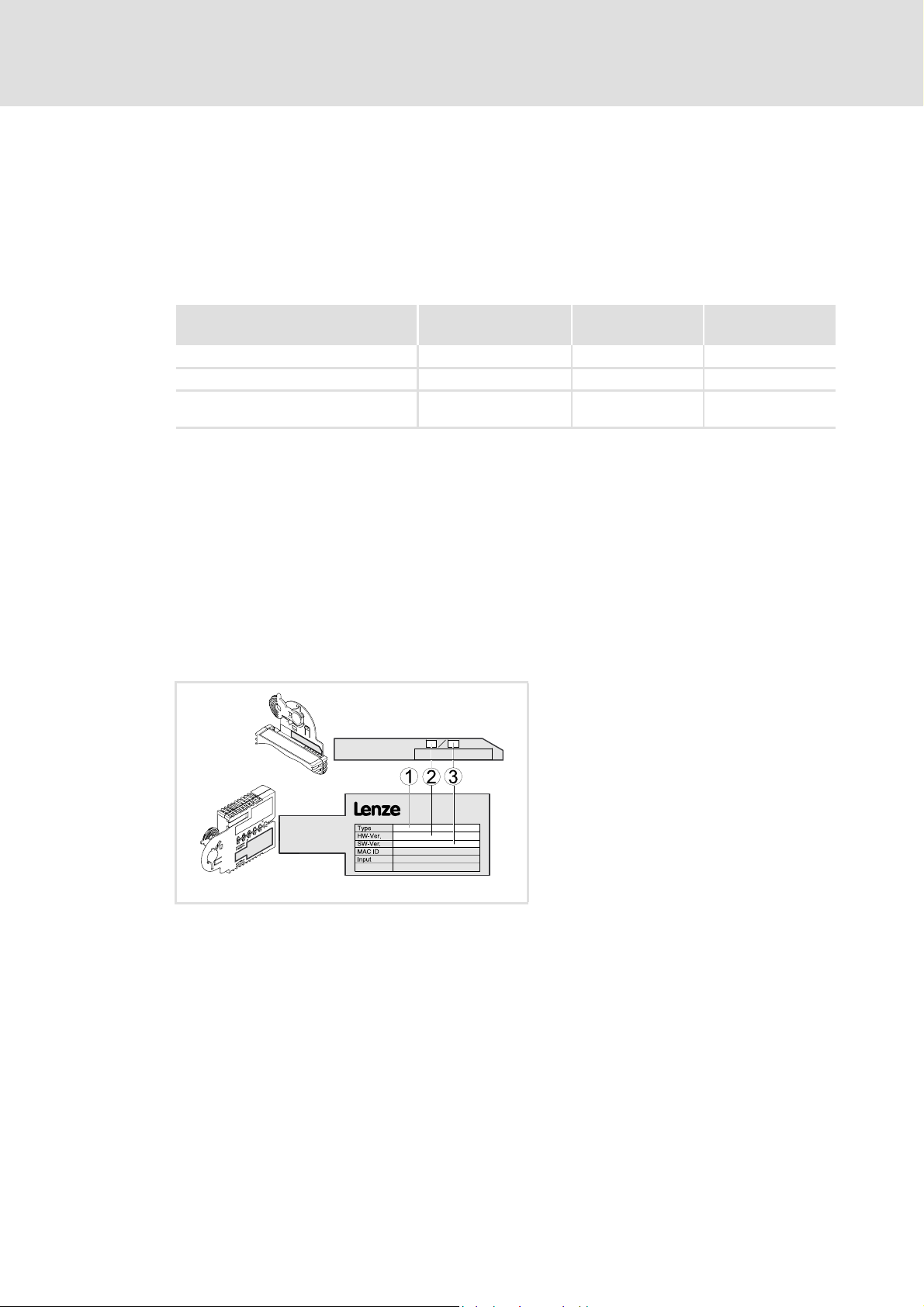
3.2 Identification
The type designation and the hardware and software version of the communication
module are specified on the nameplate:
[3-1] Identification data
version
E94ARNxxxx VA 01.00
1 Type designation (type)
E94 Product series
AVersion
Y Module identification: extension module
C Module type: communication module
CA CANopen
2 Hardware version (HW)
3 Software version (SW)
E94YCET005
From software
version
14 L EDS94AYCCA EN 5.0 - 06/2012
Page 15

3.3 Features
For many years the system bus (CAN) based on the CANopen communication profile has
been integrated in Lenze controllers. Due to the lower number of data objects available,
the functionality and compatibility of the old system bus are lower as compared with
CANopen. For parameter setting, two parameter data channels are always available to the
user while CANopen provides only one active parameter data channel (along with the
possibility to establish further channels).
The system bus (CANopen) of the Servo Drives 9400 is an advancement of the 9300
controller series' system bus (CAN).
The communication module E94AYCCA (CANopen) provides the following features:
Interface module for the system bus (CANopen), connectable to the expansion slots of
Servo Drives 9400
Internal voltage supply of the communication module via the Servo Drive 9400.
Full compatibility according to CANopen DS301, V4.02
E94AYCCA communication manual (CANopen®)
Product description
Features
Support of the NMT master/slave function "node guarding" (DS301,V4.02)
Support of the NMT slave function "heartbeat" (DS301,V4.02)
No restrictions regarding the selection of node addresses
Number of parameterisable server and client SDO channels:
– max. 10 channels with 1 ... 8 bytes
Number of parameterisable PDO channels:
– max. 4 Transmit-PDOs (TPDOs) with 1 ... 8 bytes
– max. 4 Receive-PDOs (RPDOs) with 1 ... 8 bytes
All PDO channels are functionally equivalent.
Monitoring of the RPDOs for data reception
Telegram counters for SDOs and PDOs
Bus status diagnostics
Boot-up telegram generation
Emergency telegram generation
Reset node telegram generation (with master configuration)
Sync telegram generation and response to sync telegrams:
– Transmit/receive data
– Synchronisation of the device-internal time base
Abort codes
All CAN functions parameterisable via codes
Object directory (all mandatory functions, optional functions, indexes)
EDS94AYCCA EN 5.0 - 06/2012 L 15
Page 16
E94AYCCA communication manual (CANopen®)
Product description
Terminals and interfaces
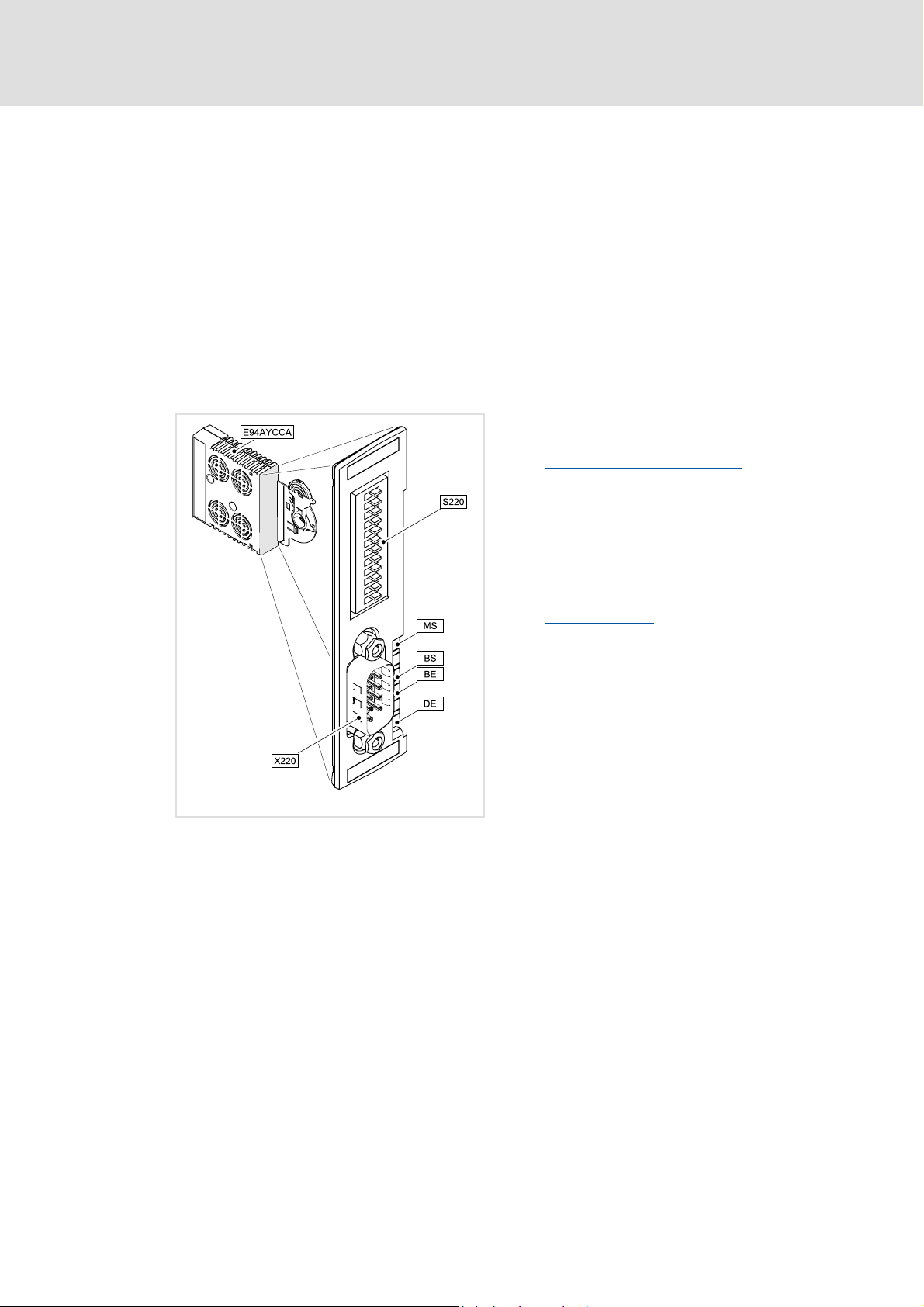
3.4 Terminals and interfaces
9-pin Sub-D plug connector for system bus connection (CANopen)
DIP switches for ...
– setting the CAN node address
– setting the baud rate
Front LEDs for diagnosing the ...
– voltage supply of the communication module;
– connection to the standard device;
– CANopen state machine and error states;
– physical CAN connection.
X220 9-pin Sub-D plug connector for the ...
System bus (CANopen) connection
( 26)
[3-2] E94AYCCA communication module (CANopen)
E94YCCA001B
S220 DIP switches for ...
• setting the CAN node address
• setting the baud rate
Possible settings via DIP switches
LED status displays for diagnostics
MS
LED status displays
BS
BE
DE
( 33)
( 86)
16 L EDS94AYCCA EN 5.0 - 06/2012
Page 17

E94AYCCA communication manual (CANopen®)
4 Technical data
4.1 General data and operating conditions
Field Values
Order designation E94AYCCA
Communication profile CANopen (DS301, V4.02)
Communication medium CAN cable according to ISO 11898-2
Network topology Line terminated on both sides
(e.g. termination with Lenze system connector EWZ0046)
Adjustable node addresses 1 ... 127
Adjustable via DIP switches or code C13350
Max. number of nodes 127
Baud rates [kbps] • 10
•20
•50
• 125
• 250
• 500
• 800
• 1000
Adjustable via DIP switches or code C13351
Process data • max. 4 TPDOs with 1 ... 8 bytes
• max. 4 RPDOs with 1 ... 8 bytes
Parameter data Max. 10 client and server SDO channels with 1 ... 8 bytes
Transfer mode for TPDOs • With change of data
• Time-controlled, 1 to x ms
• After the reception of 1 to 240 sync telegrams
Voltage supply Internal voltage supply of the communication module via the Servo Drive
9400.
Conformities, approvals • CE
•UL
Technical data
General data and operating conditions
/ C14350.
/ C14351.
"Servo Drives 9400" hardware manual
Here you can find the ambient conditions and data regarding the
electromagnetic compatibility (EMC) which also apply to the communication
module.
EDS94AYCCA EN 5.0 - 06/2012 L 17
Page 18

E94AYCCA communication manual (CANopen®)
Technical data
Supported protocols
4.2 Supported protocols
Category Protocol
Standard PDO protocols PDO write
PDO read
SDO protocols SDO download
SDO download initiate
SDO download segment
SDO upload
SDO upload initiate
SDO upload segment
SDO abort transfer
SDO block download
SDO block download initiate
SDO block download end
SDO block upload
SDO block upload initiate
SDO block upload end
NMT protocols Start remote node (master and slave)
Stop remote node (slave)
Enter pre-operational (slave)
Reset node (slave and local device)
Reset communication (slave)
Monitoring protocols Node guarding (master and slave)
Heartbeat (heartbeat producer and heartbeat consumer)
18 L EDS94AYCCA EN 5.0 - 06/2012
Page 19

4.3 Communication time
The communication time is the time between the start of a request and the arrival of the
corresponding response.
The communication times in the CAN network depend on the ...
processing time in the device;
telegram runtime (baud rate/telegram length);
bus load (especially if the bus is loaded with PDOs and SDOs at a low baud rate).
Servo Drives 9400 processing time
There are no interdependencies between parameter data and process data.
Parameter data:
– For controller-internal parameters: approx. 30 ms ± 20 ms tolerance (typically)
– For some codes the processing time can be longer.
E94AYCCA communication manual (CANopen®)
Technical data
Communication time
Process data are transported in real time.
EDS94AYCCA EN 5.0 - 06/2012 L 19
Page 20

E94AYCCA communication manual (CANopen®)
Technical data
Protective insulation
4.4 Protective insulation
Danger!
Dangerous electrical voltage
If Servo Drives 9400 are used on a corner grounded system with a rated mains
voltage ≥ 400 V, external measures need to be implemented to provide reliable
protection against accidental contact.
Possible consequences:
• Death or serious injury
Protective measures:
• If protection against accidental contact is required for the control terminals
of the controller and the connections of the plugged device modules, ...
– there must be a double isolating distance.
– the components to be connected must be provided with a second isolating
distance.
Note!
The available protective insulation in Servo Drives 9400 is implemented in
accordance with EN 61800-5-1.
20 L EDS94AYCCA EN 5.0 - 06/2012
Page 21
E94AYCCA communication manual (CANopen®)
Technical data
Protective insulation
The illustration below ...
shows the arrangement of the terminal strips and the separate potential areas of the
controller.
serves to determine the decisive protective insulation between two terminals located
in differently insulated separate potential areas.
X2
X100
X1
X3
X4
X5
MXI1
Bus
Ext. DC
MXI2
Reinforced insulation
Basic insulation
Functional insulation
X6X6
X7X7
X107
X106
X105X105
[4-1] Protective insulation according to EN61800-5-1
Terminal strip Connection Terminal strip Connection
X8X8
X100 L1, L2, L3 (only Single Drive) X1 CAN on board 9400
+UG, -UG X2 State bus
X105 U, V, W 24 V (ext.)
Rb1, Rb2 (Single Drive only) X3 Analog inputs/outputs
X106 Motor PTC X4 Digital outputs
X107 Control of the motor holding
brake
MMI
MSI
I/O
Ext. DC
E94YCXX007
X5 Digital inputs
X6 Diagnostics
X7 Resolver
X8 Encoder
MXI1, MXI2 Extension module
MMI Memory module
MSI Safety module
EDS94AYCCA EN 5.0 - 06/2012 L 21
Page 22

E94AYCCA communication manual (CANopen®)
Technical data
Protective insulation
Example
Which type of protective insulation is used between the bus terminal of the device module
in slot MXI1 or MXI2 and the mains terminal X100?
The separate potential area with the better protective insulation is decisive.
– The separate potential area of the bus terminal of the device module has a "basic
insulation".
– The separate potential area of the mains terminal has a "reinforced insulation".
Result: The insulation between the X100 mains terminal and the bus terminal is of the
"reinforced insulation" type.
22 L EDS94AYCCA EN 5.0 - 06/2012
Page 23
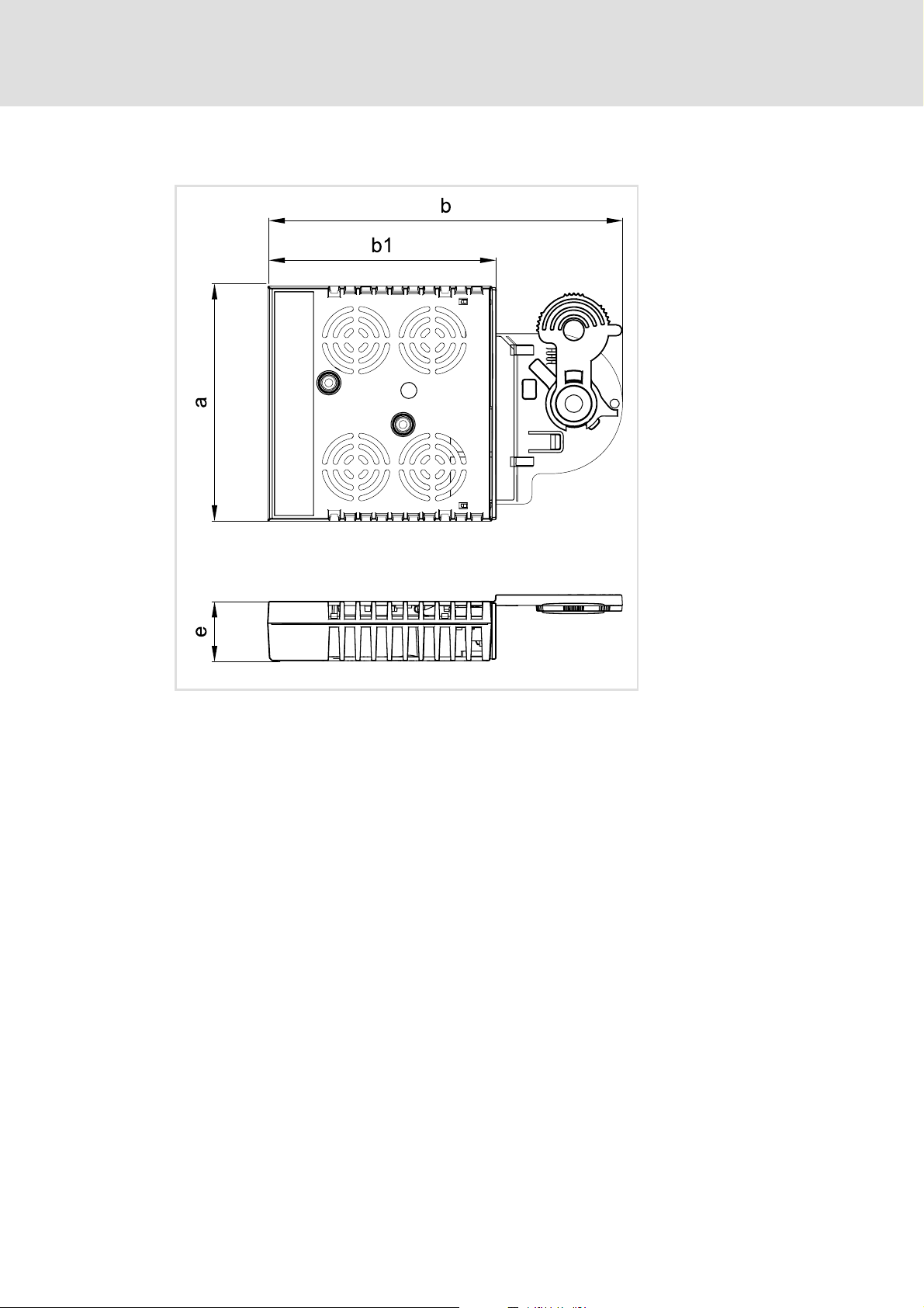
4.5 Dimensions
E94AYCCA communication manual (CANopen®)
Technical data
Dimensions
a 89 mm
b 134 mm
b1 87 mm
e 23 mm
[4-2] Dimensions
E94YCXX005
EDS94AYCCA EN 5.0 - 06/2012 L 23
Page 24

E94AYCCA communication manual (CANopen®)
Installation
5 Installation
Stop!
Electrostatic discharge
Electronic components in the communication module can be damaged or
destroyed by electrostatic discharge.
Possible consequences:
• The communication module is defective.
• Fieldbus communication is faulty or not possible.
Protective measures
• Before touching the module, make sure that you are free of electrostatic
charge.
24 L EDS94AYCCA EN 5.0 - 06/2012
Page 25
5.1 Mechanical installation
Note!
• Only one communication module E94AYCCA (CANopen) may be inserted per
Servo Drive 9400.
• The slot used (MX1 or MX2) can be selected freely.
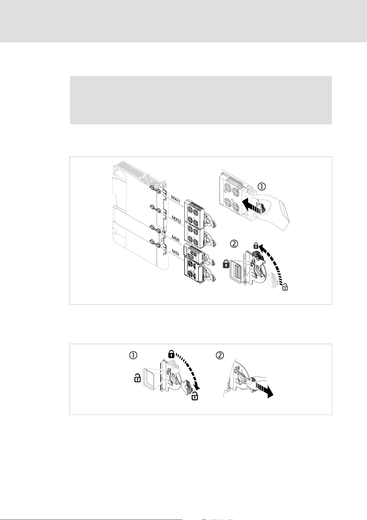
5.1.1 Mounting
E94AYCCA communication manual (CANopen®)
Installation
Mechanical installation
[5-1] Mounting
5.1.2 Dismounting
[5-2] Dismounting
E94YCXX001G
E94AYCXX001H
EDS94AYCCA EN 5.0 - 06/2012 L 25
Page 26
E94AYCCA communication manual (CANopen®)
OFF
ON
Installation
Electrical installation
5.2 Electrical installation
Documentation of the standard device, control system, and plant/machine
Observe the notes and wiring instructions stated.
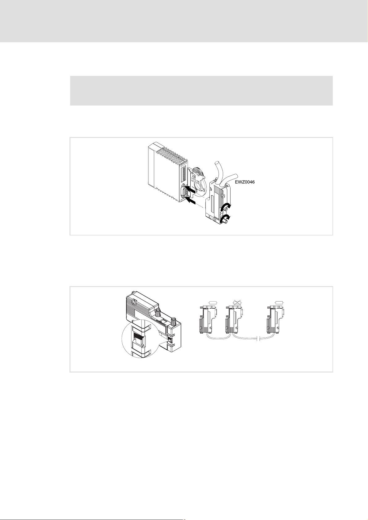
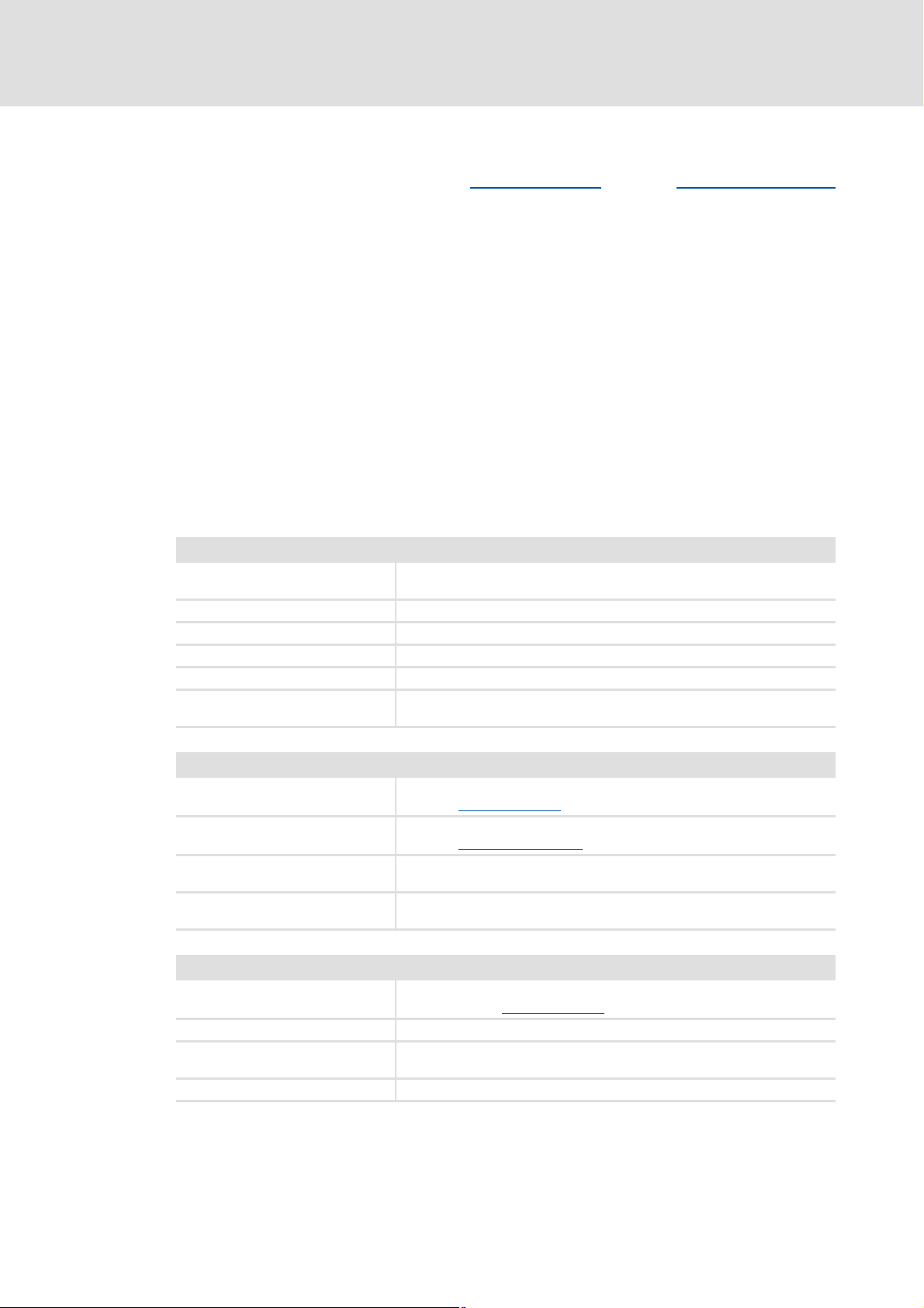
5.2.1 System bus (CANopen) connection
E94YCCA002A
The system bus (CANopen) must be terminated with resistors (120 Ω) between CAN-
low and CAN-high.
The Lenze system connector EWZ0046 with integrated terminating resistor complies
with the DS102-1 recommendation of the CAN user organisation CiA. The system
connector is not contained in the scope of supply of the communication module.
On
120
EWZ0046
L
ð
2181FEW004
L
EWZ0046
120 120
On
OFF
ON
F
F
O
N
O
Off
EWZ0046
L
EWZ0046
L
ð
ð
ð
OUTIN IN IN
26 L EDS94AYCCA EN 5.0 - 06/2012
Page 27

Assignment of the 9-pin Sub-D plug connector
View Pin Assignment
1
5
6
9
1 -
2 CAN-LOW
3 CAN-GND
4 -
5 -
6 -
7 CAN-HIGH
8 -
9 -
5.2.2 Specification of the bus cable
We recommend the use of CAN cables according to ISO 11898-2:
E94AYCCA communication manual (CANopen®)
Installation
Electrical installation
CAN cable according to ISO 11898-2
Cable type Twisted in pairs with shield
Impedance 120 Ω (95 ... 140 Ω)
Cable resistance/cross-section
Cable length ≤ 300 m:
Cable length 301 ... 1000 m:
Signal propagation delay ≤ 5 ns/m
≤ 70 mΩ/m / 0.25 ... 0.34 mm
≤ 40 mΩ/m / 0.5 mm
2
(AWG20)
2
(AWG22)
EDS94AYCCA EN 5.0 - 06/2012 L 27
Page 28

E94AYCCA communication manual (CANopen®)
Installation
Electrical installation
5.2.3 Bus cable length
Note!
• It is absolutely necessary to comply with the permissible cable lengths.
• If the total cable lengths of the CAN nodes differ for the same baud rate, the
smaller value must be used to determine the max. cable length.
• Observe the reduction of the total cable length due to the signal delay of the
repeater.Checking the use of repeaters
5.2.3.1 Total cable length
The baud rate also determines the total cable length.
Baud rate [kbps] Max. bus length [m]
10 8075
20 4012
50 1575
125 600
250 275
500 112
800 38
1000 12
( 30)
28 L EDS94AYCCA EN 5.0 - 06/2012
Page 29

5.2.3.2 Segment cable length
The segment cable length is determined by the cable cross-section used and by the number
of nodes. Repeaters divide the total cable length into segments. If no repeaters are used,
the segment cable length is identical to the total cable length.
E94AYCCA communication manual (CANopen®)
Installation
Electrical installation
Max. number of
nodes per segment
2 240 m 430 m 650 m 940 m
5 230 m 420 m 640 m 920 m
10 230 m 410 m 620 m 900 m
20 210 m 390 m 580 m 850 m
32 200 m 360 m 550 m 800 m
63 170 m 310 m 470 m 690 m
100 150 m 270 m 410 m 600 m
Cable cross-section (can be interpolated)
0.25 mm
(AWG 24)
2
0.50 mm
(AWG 21)
2
0.75 mm
(AWG 19)
2
1.00 mm
(AWG 18)
Example: selection help
Given
Total cable length to be
implemented
Number of nodes 63
Results
Max. possible baud rate 250 kbps
Cable cross-section required
(interpolated)
Cable cross-section of standard CAN
cable
200 m
(derived from table Total cable length
0.30 mm
(derived from the table Segment cable length
0.34 mm
Specification of the bus cable
2
(AWG23)
2
(AWG22)
( 28))
( 27)
( 29))
2
EDS94AYCCA EN 5.0 - 06/2012 L 29
Page 30
E94AYCCA communication manual (CANopen®)
Installation
Electrical installation
5.2.3.3 Checking the use of repeaters
Compare the values derived from tables Total cable length
( 29).
( 28) and Segment cable length
If the sum of the segment cable lengths is smaller than the total cable length to be
implemented, either repeaters must be used or the cable cross-section must be
increased.
If the use of repeaters reduces the max. possible total cable length so much that it is
smaller than the total cable length to be implemented, then the cable cross-section
must be increased or less repeaters must be used or the baud rate must be decreased.
The use of a further repeater is recommended as ...
– service interface
Advantage: trouble-free connection during bus operation is possible.
– calibration interface
Advantage: the calibration/programming unit remains electrically isolated.
Example
Given
Total cable length to be
implemented
Number of nodes 32
Cable cross-section 0.50 mm
Baud rate 125 kbps
Repeater used Lenze repeater EMF2176IB
Reduction of the max. total cable
length per repeater (EMF2176IB)
450 m
30 m
2
(AWG 20)
Results
Max. possible total cable length 600 m
(see table Total cable length
Max. segment cable length 360 m
(see table Segment cable length
Comparison The max. segment cable length is smaller than the total cable length to be
implemented.
Conclusion A repeater must be installed at the determined max. segment cable length
of 360 m.
Results with 1 repeater
Max. possible total cable length 570 m
(Reduction of the Total cable length
Sum of the segment cable lengths 720 m
Comparison Both the possible total cable length and the segment cable lengths are larger
than the total cable length to be implemented.
Conclusion 1 repeater is sufficient to implement the total cable length of 450 m.
( 28))
( 29))
( 28) by 30 m)
30 L EDS94AYCCA EN 5.0 - 06/2012
Page 31

5.2.4 Voltage supply
The communication module is only internally supplied with voltage via the standard
device.
If the standard device fails, data transfer between the communication module and
other CAN nodes is interrupted.
E94AYCCA communication manual (CANopen®)
Installation
Electrical installation
EDS94AYCCA EN 5.0 - 06/2012 L 31
Page 32

E94AYCCA communication manual (CANopen®)
Commissioning
Before initial switch-on
6 Commissioning
During commissioning, the controller receives system-specific data, e.g. motor
parameters, operating parameters, responses, and parameters for the fieldbus
communication. In case of Lenze devices, this is done via codes.
The codes for the controller and for the communication are saved as a non-volatile data set
in the memory module.
In addition to codes for the configuration, there are codes for diagnosing and monitoring
the nodes.
Note!
When parameterising the communication module, please note that the code
number depends on the slot of the Servo Drive 9400 which the communication
module is plugged into.
The first two digits of the code number indicate the slot:
•C13nnn for slot MXI1
Parameters of the communication module for slot MXI1
•C14nnn for slot MXI2
Parameters of the communication module for slot MXI2
Furthermore, the Communication-relevant parameters of the standard device
( 101)
must be set.
6.1 Before initial switch-on
Stop!
Before switching on the controller for the first time, check ...
• the entire wiring with regard to completeness, earth fault and short circuit.
• whether the bus system is terminated by a bus terminating resistor at the
physically first and last node.
System bus (CANopen) connection
( 107)
( 128)
( 26)
32 L EDS94AYCCA EN 5.0 - 06/2012
Page 33

E94AYCCA communication manual (CANopen®)
6.2 Possible settings via DIP switches
Commissioning
Possible settings via DIP switches
O
O
O
N
N
N
[6-1] DIP switch
643216 8
643216 8
643216 8
cdba
cdba
cdba
Baud
Baud
Baud
CAN Address
CAN Address
CAN Address
6.2.1 Setting the node address
If several CAN nodes are interconnected, their node addresses must differ from each
other.
The node address can be set with the DIP switches 1 ... 64 or via the »Engineer« (code
C13350
/ C14350).
Valid address range: 1 … 127
Prerequisite At least one switch 1…64=ON Switches 1...64=OFF
The labelling on the package corresponds to the values of the individual DIP switches for
determining the node address.
DIP switch 64 32 16 8 4 2 1
Switch position OFF OFF ON OFF ON ON ON
Value 00
Node address = Sum of the values = 16 + 4 + 2 + 1 = 23
421
421
421
The front DIP switches can be used to set:
address (switches 1 ... 64)
baud rate (switches a ... d)
9400CAN003
Node address determined by ...
DIP switch C13350 / 14350
DIP switch positions for setting the CAN node address
Lenze setting: all switches OFF
16 0 4 2 1
( 178)
Note!
Switch the voltage supply of the communication module off and then on again
to activate altered settings.
Tip!
The node address resulting from the DIP switch setting applied at last mains
power-up is indicated under C13349/1
EDS94AYCCA EN 5.0 - 06/2012 L 33
/ C14349/1.
Page 34

E94AYCCA communication manual (CANopen®)
Commissioning
Possible settings via DIP switches
6.2.2 Setting the baud rate
The baud rate can be set with the DIP switches a...d or via the »Engineer« (code
C13351
If several CAN nodes are interconnected, their baud rates must be identical.
d c b a
OFF ON ON OFF 10 kbps
OFF ON OFF ON 20 kbps
OFF OFF ON ON 50 kbps
OFF OFF ON OFF 125 kbps
OFF OFF OFF ON 250 kbps
OFF OFF OFF OFF 500 kbps
ON ON ON OFF 800 kbps
OFF ON OFF OFF 1000 kbps
OFF ON ON ON Automatic detection
/ C14351).
Switch positions Baud rate
Note!
Switch the voltage supply of the standard device off and then on again to
activate altered settings.
Tip!
The baud rate resulting from the DIP switch setting applied at last mains power-up
is indicated under C13349/2
/ C14349/2.
34 L EDS94AYCCA EN 5.0 - 06/2012
Page 35

6.3 Settings in the »Engineer«
E94AYCCA communication manual (CANopen®)
Commissioning
Settings in the »Engineer«
Go to the Settings tab to ...
set the node address (C13350
Setting the node address
select the procedure for automatic allocation of the COB-IDs in the »Engineer«.
configure the CAN node as a master or slave (C13352
display the time that must elapse after mains power-up before the CAN NMT
master transmits the "Start remote node" telegram via the system bus (CANopen)
(C13378 / C14378).
( 33)
/ C14350).
/ C14352).
EDS94AYCCA EN 5.0 - 06/2012 L 35
Page 36

E94AYCCA communication manual (CANopen®)
Commissioning
Initial switch-on
6.4 Initial switch-on
Documentation of Servo Drive 9400
Observe the safety instructions and residual hazards stated.
Note!
Establishing communication
When the communication module is externally supplied, the standard device
must also be switched on for establishing communication.
After communication has been established, communication of the externally
supplied module is independent of the on/off state of the standard device.
Activating changed settings
In order to activate changed settings ...
• execute device command "11: Save start parameters" via standard device
code C00002 and ...
• then execute a "CAN reset node" on the node using C00002 = 92 or switch off
and on again the voltage supply of the communication module.
Protection against uncontrolled restart
After a fault (e.g. short-term mains failure), it is sometimes not wanted or even
impermissible that the drive restarts.
In the Lenze setting of the Servo Drives 9400, the restart protection is activated.
Via the standard device code C00142 ("Auto restart after mains connection") you
can set the restart behaviour of the controller:
• C00142 = "0: Inhibited" (Lenze setting)
– The controller remains inhibited (even if the fault is no longer active).
– The drive starts up in a controlled manner by explicit controller enable:
LOW-HIGH edge at digital input X5/RFR.
• C00142 = "1: Enabled"
– An uncontrolled restart of the drive is possible.
36 L EDS94AYCCA EN 5.0 - 06/2012
Page 37

E94AYCCA communication manual (CANopen®)
7 Data transfer
Via the CANopen interface, process data and parameter values can be exchanged between
the CAN nodes. In addition, the interface enables the connection of further modules such
as distributed terminals, operator and input devices (HMIs), or external controls and
control systems.
The interface transfers CAN objects following the CANopen communication profile
(DS301, V4.02) ) developed by the umbrella organisation of CiA (CAN in Automation) in
conformity with the CAL (CAN Application Layer).
7.1 Structure of the CAN data telegram
Data transfer
Structure of the CAN data telegram
6WDUW 575ELW
,GHQWLILHU 8VHUGDWD
%LW %LW %LW %LW %LW %LW %LW %LW %LW
[7-1] Basic structure of the CAN telegram
&RQWUROILHOG
&5&VHTXHQFH
%\WH
1HWZRUNPDQDJHPHQW
3URFHVVGDWD
3DUDPHWHUGDWD
&5&GHOLPLWHU $&.GHOLPLWHU
$&.VORW (QG
The identifier and the user data are described in detail in the following subchapters. The
other signals refer to the transfer characteristics of the CAN telegram that are not
described in this documentation.
Tip!
For further information please refer to the website of the CiA (CAN in Automation)
user organisation:
www.can-cia.org
EDS94AYCCA EN 5.0 - 06/2012 L 37
Page 38

E94AYCCA communication manual (CANopen®)
Data transfer
Structure of the CAN data telegram
7.1.1 Identifier
The principle of the CAN communication is based on a message-oriented data exchange
between a transmitter and many receivers. All nodes can transmit and receive quasisimultaneously.
The identifier, also called "COB-ID" (Communication Object Identifier), is used to control
which node is to receive a transmitted message. In addition to the addressing, the
identifier contains information on the priority of the message and the type of the user
data.
The identifier consists of a basic identifier and the node address of the node to be
addressed:
Identifier (COB-ID) = basic identifier + node address (node ID)
Exception:
management and sync telegrams, the identifier can be assigned freely by the user (either
manually or automatically by a network configurator) or is firmly allocated.
Node address (node ID)
For the purpose of unique identification, a node address, also referred to as node ID, in the
valid address range (1 ... 127) is to be assigned to each node within the CAN network.
A node address may not be assigned more than once within a network.
The node address can be configured with the DIP switches of the communication
module or with code C13350
Setting the node address
For process data, heartbeat and emergency objects as well as network
/ C14350.
( 33)
38 L EDS94AYCCA EN 5.0 - 06/2012
Page 39

E94AYCCA communication manual (CANopen®)
Data transfer
Structure of the CAN data telegram
Identifier assignment
The system bus (CANopen) is message-oriented and not node-oriented. Each message has
a unique identification, the identifier. In the case of CANopen, a node-orientation is
achieved by the fact that for each message there is only one sender.
The basic identifiers for network management (NMT) and sync as well as the basic SDO
channel (SDO1) are specified in the CANopen protocol and cannot be changed.
In the Lenze setting, the basic identifiers of the PDOs are preset according to the
"Predefined Connection Set" of DS301, V4.02. They can be changed via parameters/
indexes if required.
Identifiers of the process data objects
Object Direction Basic identifier
from the device to the device dec hex
Network management (NMT) 0 0
Sync 128 80
Emergency z 128 80
PDO1
(Process data channel 1)
PDO2
(Process data channel 2)
PDO3
(Process data channel 3)
PDO4
(Process data channel 4)
SDO1
(Basic SDO channel)
SDO2 ... SDO10
(Parameter data channel 2 ... 10)
Node guarding, heartbeat z 1792 700
TPDO1
RPDO1
TPDO2
RPDO2
TPDO3
RPDO3
TPDO4
RPDO4
z 384 180
z 640 280
z 896 380
z 1152 480
z 1408 580
z 1472 5C0
( 46)
z 512 200
z 768 300
z 1024 400
z 1280 500
z 1536 600
z 1600 640
EDS94AYCCA EN 5.0 - 06/2012 L 39
Page 40

E94AYCCA communication manual (CANopen®)
Data transfer
Structure of the CAN data telegram
7.1.2 User data
All nodes communicate with each other by exchanging data telegrams via the system bus
(CANopen). The user data area of the CAN telegram contains network management data,
parameter data or process data:
Network management data
(NMT data)
Control information on start, stop, reset, etc. of communication to certain or all nodes
of the CAN network.
Process data
(PDOs – Process Data Objects)
Process data are transferred via the process data channel.
The controller can be controlled using process data.
Process data are not
Process data are transferred between the host and the nodes to ensure a continuous
exchange of current input and output data.
Process data usually are unscaled/scalable raw data
Process data are, for instance, setpoints and actual values.
Parameter data
(SDOs – Service Data Objects)
Parameter data are the CANopen indexes or, in the case of Lenze devices, the codes.
The parameters are, for instance, set for the initial system set-up during
commissioning or when material is changed on the production machine.
Parameter data are transmitted as SDOs via the parameter data channel. They are
acknowledged by the receiver, i.e. the sender receives a feedback about the
transmission being successful or not.
The parameter data channel enables access to all Lenze parameters (codes) and
CANopen indexes.
Parameter changes are automatically saved in the controller until the mains is
switched.
saved in the controller.
In general, the parameter transfer is not time-critical.
Parameter data are, for instance, operating parameters, diagnostic information and
motor data.
40 L EDS94AYCCA EN 5.0 - 06/2012
Page 41

E94AYCCA communication manual (CANopen®)
Communication phases / network management
7.2 Communication phases / network management
Regarding communication via the system bus (CANopen), the drive distinguishes between
the following states:
Status Explanation
"Initialisation"
(Initialisation)
"Pre-operational"
(before being ready for operation)
"Operational"
(ready for operation)
"Stopped"
(Stopped)
After power-up, initialisation is executed.
• During this phase, the controller does not take part in the data transfer on
the system bus (CANopen).
• All CAN-relevant parameters are written with their standard values
again.
• After initialisation has been completed, the controller is automatically set
to the "pre-operational" status.
Parameter data can be received, process data is ignored.
Parameter data and process data can be received!
Only network management telegrams can be received.
Data transfer
Communication object Initialisation Pre-operational Operational Stopped
PDO z
SDO zz
Sync zz
Emergency zz
Boot-up z
Network management (NMT) zzz
Tip!
In every state, the initialisation can be re-executed partly or completely by
transmitting appropriate network management telegrams.
EDS94AYCCA EN 5.0 - 06/2012 L 41
Page 42

E94AYCCA communication manual (CANopen®)
Data transfer
Communication phases / network management
7.2.1 State transitions
,QLWLDOLVDWLRQ
[7-2] NMT state transitions in the CAN network
3UH2SHUDWLRQDO
2SHUDWLRQDO
6WRSSHG
Transition NMT command State after
Effect on process and parameter data after state change
change
(1) - Initialisation Initialisation starts automatically when the mains is
switched on.
• During initialisation, the controller does not take part in
the data transfer.
• After initialisation has been completed, the node sends a
boot-up message with an individual identifier and
automatically changes to the "pre-operational" status.
(2) - Pre-operational In this phase, the master determines the way in which the
node(s) takes/take part in the communication.
From here, the states are changed over by the master for the entire network.
• A target address contained in the NMT command specifies the receiver(s).
• If the 9400 controller has been configured as a CAN master, the state automatically changes to
"operational" after a waiting time (C13378
/ C14378) has expired, and the NMT command
0x0100 ("Start remote node") is sent to all nodes.
• Data can only be exchanged via process data objects if the state is "Operational".
(3), (6) 0x01 xx
Start Remote Node
Operational Network management, sync and emergency telegrams as
well as process data (PDO) and parameter data (SDO) are
active.
Optional: When the state is changed, event and timecontrolled process data (PDOs) will be sent once.
(4), (7) 0x80 xx
Enter Pre-Operational
(5), (8) 0x02 xx
Stop Remote Node
(9), (10), (11) 0x81 xx
Reset node
(12), (13), (14) 0x82 xx
Reset communication
Pre-operational Network management, sync and emergency telegrams as
well as parameter data (SDO) are active.
Stopped Only network management telegrams can be received.
Initialisation Initialisation of all CAN-relevant parameters (DS301, V4.02)
with the stored values.
Initialisation of all CAN-relevant parameters (DS301, V4.02)
with the stored values.
Meaning of the node address in the NMT command:
• xx = 0x00: With this assignment, all nodes are addressed by the telegram (broadcast telegram).
The state can be changed for all nodes at the same time.
• xx = Node-ID: If a node address is indicated, the state will only be changed for the node
addressed.
42 L EDS94AYCCA EN 5.0 - 06/2012
Page 43

E94AYCCA communication manual (CANopen®)
7.2.2 Network management telegram (NMT)
The telegram for the network management contains the identifier "0" and the command
included in the user data, which consists of the command byte and the node address.
,GHQWLILHU 8VHUGDWD%\WH
&2%,'
%LW %LW %LW %LW %LW %LW %LW %LW %LW
[7-3] Network management telegram for changing the communication phases
Command specifier (cs) NMT command
dec hex
1 0x01 Start Remote Node
20x02Stop Remote Node
128 0x80 Enter Pre-Operational
129 0x81 Reset node
130 0x82 Reset communication
FRPPDQG
VSHFLILHU
FV
Data transfer
Communication phases / network management
QRGH
DGGUHVV
QRGH,'
The changeover of the communication phases is carried out by one node, the CAN master,
for the entire network. The role of the CAN master can also assumed by the drive controller.
Parameterising the controller as a CAN master
( 44)
Example:
Data can only be exchanged via the process data objects in the "Operational" state. To
change all nodes on the bus from "Pre-Operational" to "Operational" via the CAN master,
the following identifiers and user data must be set as follows in the transmit telegram:
Identifier: 0x00 (network management)
User data: 0x0100 (NMT command "Start Remote Node" to all nodes)
EDS94AYCCA EN 5.0 - 06/2012 L 43
Page 44

E94AYCCA communication manual (CANopen®)
Data transfer
Communication phases / network management
7.2.3 Parameterising the controller as a CAN master
If the initialisation of the system bus (CANopen) and the state change from "preoperational" to" operational" is not carried out by a higher-level control system, the
controller can be defined to be a "quasi" master to take over this task.
The controller can be configured to be a CAN master in C13352
As a CAN master, the controller sets all
telegram) to the "operational" communication state using the "Start remote node"
NMT telegram. Only this communication state enables a data exchange via the process
data objects.
In C13378
switching before the controller transmits the "Start remote node" NMT telegram on the
system bus (CANopen).
Parameter Information Lenze setting
C13352 / C14352 CAN slave/master Slave
C13378
/ C14378 CAN delay boot-up - Operational 3000 ms
/ C14378, a delay time can be set. This delay time must elapse after mains
nodes connected to the bus (broadcast
/ C14352.
Value Unit
Note!
Changing the master/slave operation in C13352 / C14352 will only be effective
• after switching the mains power of the controller off and then on again
or
• by sending the NMT telegram "Reset Node" or "Reset Communication" to the
controller.
As an alternative to the "Reset node" NMT telegram, the device command
C00002 = "92: CAN module: reset node" can be used to reinitialise the CANspecific device parameters.
Tip!
The master functionality is only required for the initialisation phase of the drive
system.
44 L EDS94AYCCA EN 5.0 - 06/2012
Page 45

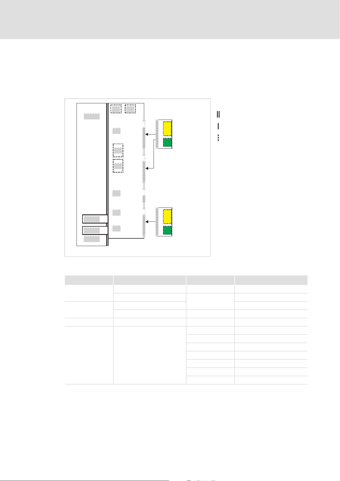
8 Process data transfer
E94AYCCA communication manual (CANopen®)
Process data transfer
[8-1] PDO data transfer from / to the higher-level host system
For the transfer of process data, four separated process data channels (PDO1 ... PDO4) are
available.
Definitions
Process data telegrams between the host and the devices are distinguished as follows:
– Process data telegrams to
– Process data telegrams from
The CANopen process data objects are designated as seen from the node's view:
– Receive PDO (RPDOx): process data object received by a node
– Transmit PDO (TPDOx): process data object transmitted by a node
the device (RPDO)
the device (TPDO)
Note!
Data can only be exchanged via the process data objects if the state is
"Operational".
Communication phases / network management
( 41)
EDS94AYCCA EN 5.0 - 06/2012 L 45
Page 46

E94AYCCA communication manual (CANopen®)
Process data transfer
Identifiers of the process data objects
8.1 Identifiers of the process data objects
In the Lenze setting, the identifier for the process data objects PDO1 ... PDO4 results from
a basic identifier and the node address set in C13350
Identifier (COB-ID) = basic identifier + node address (node ID)
In the Lenze setting, the basic identifiers of the PDOs are preset according to the
"Predefined Connection Set" of DS301, V4.02.
The identifiers for the PDOs can be set individually via the Lenze codes and CANopen
indexes listed in the following table. Thus, you can also set an identifier independently
of the node address for certain PDOs.
Process data object Basic identifier Individual setting
dec hex Lenze code CANopen index
PDO1 RPDO1 512 0x200 C13321/1
TPDO1 384 0x180 C13320/1
PDO2 RPDO2 768 0x300 C13321/2
TPDO2 640 0x280 C13320/2
PDO3 RPDO3 1024 0x400 C13321/3
TPDO3 896 0x380 C13320/3
PDO4 RPDO4 1280 0x500 C13321/4
TPDO4 1152 0x480 C13320/4
/ C14350:
I-1400/1
C14321/1
I-1800/1
C14320/1
I-1401/1
C14321/2
I-1801/1
C14320/2
I-1402/1
C14321/3
I-1802/1
C14320/3
I-1403/1
C14321/4
I-1803/1
C14320/4
Note!
When the node address has been changed (C13350 / C14350) and then "Reset
node" (C00002 = 92) has been executed, the subcodes of C13320
C13321
respective basic identifier and the node address set.
Tip!
The "Predefined Connection Set" can be re-established anytime using the following
device commands of C00002:
• "93: CAN on board: Pred.Connect.Set" for CAN on board
• "94: CAN module: Pred.Connect.Set" for communication module E94AYCCA
/ C14320 and
/ C14321 are automatically reset to the identifiers resulting from the
46 L EDS94AYCCA EN 5.0 - 06/2012
Page 47

8.2 Transmission type
The process data objects are transmitted in an event-controlled or time-controlled way.
Event-controlled: The PDO is sent if a special device-internal event has occurred, for
instance, when the data contents of the TPDO have changed or when a transmission
cycle time has elapsed.
Synchronous: A TPDO (or RPDO) is transmitted (or received) after the device has
received a sync telegram (with identifier 0x80).
Cyclically: The PDOs are transmitted in fixed time intervals after the transmission cycle
time has elapsed.
The table shows that combinations of logic operations (AND, OR) are also possible between
the different transmission modes:
Transmission type PDO transmission Logic operation
0 zzAND
1 ... 240 z -
254, 255 zzOR
E94AYCCA communication manual (CANopen®)
Process data transfer
Transmission type
cyclic synchronous event-controlled
Transmission type Description
0 The PDO is transmitted at every sync in an event-controlled manner (e. g. by means of a bit
1 ... 240 SYNC (with response)
254, 255 Event-controlled (with mask) with cyclic overlay
change within the PDO).
• Selection n = 1: The PDO is transmitted with every
• Selection 1 < n ≤ 240: The PDO is transmitted with every n-th
If this value is entered, the PDO transmission is event-controlled or
(Note: The values "254" and "255" have the same meaning).
For cyclic overlay, a cycle time must be set for the respective PDO. In this case, cyclic
transmission takes place in addition to event-controlled transmission (e.g. through a bit
change in the PDO).
sync.
sync.
cyclic.
EDS94AYCCA EN 5.0 - 06/2012 L 47
Page 48

E94AYCCA communication manual (CANopen®)
Process data transfer
Transmission type
The communication parameters (as e.g. transmission mode and cycle time) can be freely
adjusted for any PDO and independent of the settings of other PDOs:
Parameter Information Lenze setting
C13322/1...4
C14322/1...4
C13323/1...4
C14323/1...4
C13324/1...4
C14324/1...4
C13356/1...4
C14356/1...4
CAN TPDOx Tx mode 254
CAN RPDOx Rx mode 254
CAN TPDOx delay time 0 1/10 ms
CAN TPDOx cycle time 0 ms
Tip!
The setting can also be made via the following CANopen objects:
• I-1400
• I-1800
... I-1403: Communication parameters for RPDO1 ... RPDO4
... I-1803: Communication parameters for TPDO1 ... TPDO4
Value Unit
48 L EDS94AYCCA EN 5.0 - 06/2012
Page 49

E94AYCCA communication manual (CANopen®)
8.3 Masking of the TPDOs for event control
For TPDO1 ... TPDO4, a mask can be parameterised for every byte. In case of eventcontrolled transmission of a PDO, only the masked bits are used for the event control.
Mask "0x0" means that no bit of the corresponding byte triggers the transmission.
Mask "0xff" means that each bit of the corresponding byte can trigger the
transmission.
Short overview: Parameters for masking the TPDOs
Parameter Information Lenze setting
C13311/1...8
C14311/1...8
C13312/1...8
C14312/1...8
C13313/1...8
C14313/1...8
C13314/1...8
C14314/1...8
CAN TPDO1 mask byte x 0x00
CAN TPDO2 mask byte x 0x00
CAN TPDO3 mask byte x 0x00
CAN TPDO4 mask byte x 0x00
Process data transfer
Masking of the TPDOs for event control
EDS94AYCCA EN 5.0 - 06/2012 L 49
Page 50

E94AYCCA communication manual (CANopen®)
Process data transfer
Synchronisation of PDOs via sync telegram
8.4 Synchronisation of PDOs via sync telegram
In case of cyclic transmission, one or several PDOs are transmitted or received at fixed time
intervals. For synchronising the cyclic process data, an additional special telegram, the sync
telegram, is used.
The sync telegram is the trigger point for the transmission of process data from the
frequency inverters to the master and for the acceptance of process data from the
master by the slaves.
For sync-controlled process data processing, the sync telegram must be generated
accordingly.
The response to a sync telegram is determined by the transmission type selected.
Transmission type
General procedure
( 47)
1 Sync cycle time (C01121)
[8-2] Sync telegram
A. After the sync telegram has been received, the slaves send the synchronous process
data to the master (TPDOs). The master reads them as process input data.
B. When the sending process has been completed, the slaves (RPDOs) receive the process
output data (from the master).
– All other telegrams (e.g. parameters or the event-controlled process data) are
accepted acyclically by the slaves after the transmission has been completed
successfully.
– The acyclic data are not shown in figure [8-2]
cycle time is dimensioned.
C. The data in the slave is accepted with the next sync telegram if the Rx mode is set to
1 ... 240. When the Rx mode is set to 254 or 255 the data is accepted in the next device
cycle independent of the sync telegram.
SYNC SYNC
01 2
They must be considered when the
50 L EDS94AYCCA EN 5.0 - 06/2012
Page 51

8.4.1 Parameter setting
Short overview: Parameters for synchronisation via sync telegram
Parameter Information Lenze setting Assignment
C13367
C14367
C13368
C14368
C00369/1
C01120
C01121
C01122
C01123
C01124
C01130
E94AYCCA communication manual (CANopen®)
Process data transfer
Synchronisation of PDOs via sync telegram
Value Unit Sync
CAN SYNC Rx identifier 128 z
CAN SYNC Tx identifier 128 z
CAN SYNC transmit cycle time 0 ms z
Sync source Off z
Sync cycle time 1000 μs z
Sync phase position 400 μs z
Sync tolerance 0 μs z
Sync-PLL increment 109 ns z
Sync application cycle 1000 μs z
Master
Sync
Slave
Sync source
C01120
is used to select the source of the synchronisation signals. Basically, only one
source can synchronise the node.
Sync cycle time
Time with which the internal phase-locking loop (PLL) expects the synchronisation signals.
The time must be set in C01121
selected in C01120
.
in accordance with the cycle of the synchronisation source
Note!
For synchronisation via the system bus (CANopen), only integer multiples of
1000 μs should be set in C01121
Example: For the system bus (CANopen), the interval between two synchronisation signals
has been set to 2 ms. If the system bus (CANopen) is to be used as synchronisation source,
a sync cycle time of 2000 μs must be set in C01121
.
.
EDS94AYCCA EN 5.0 - 06/2012 L 51
Page 52

E94AYCCA communication manual (CANopen®)
Process data transfer
Synchronisation of PDOs via sync telegram
Sync phase position
The phase position defines the zero point of time for the application relating to the
synchronisation signal (bus cycle). Since PDO processing is integrated in the system part of
the application, the instant of the PDO acceptance also changes if the phase position is
changed.
If 0 is set, the application is started together with the synchronisation signal.
If a value > 0 is set, the application starts by the set time interval before the
synchronisation signal arrives (the phase position acts negatively).
Example: If the phase position is set to 400 μs, the system part of the application starts
400 μs before the synchronisation signal arrives.
Note!
From Servo Drive 9400 software version V3.0:
The effect of the sync phase position can be influenced by the application cycle
set in C01130
. For the Lenze setting of C01130, the behaviour remains as before.
Sync tolerance
Time slot for monitoring the synchronisation signal via the LS_SyncInput system block.
If the last synchronisation signal has been within this time slot around the expected
value, the SYNC_bSyncInsideWindow output of the LS_SyncInput system block is set to
TRUE.
This setting does not affect the synchronisation process.
Sync-PLL increment
If the cycle times of the synchronisation signal and the phase-locking loop (PLL) differ from
each other, the setting in C01124
can be readjusted.
If the system bus (CANopen) is used as synchronisation source, the recommended time
increment for deviations is 109 ns (Lenze setting).
defines the increment with which the phase-locking loop
52 L EDS94AYCCA EN 5.0 - 06/2012
Page 53

Sync application cycle
E94AYCCA communication manual (CANopen®)
Process data transfer
Synchronisation of PDOs via sync telegram
This parameter influences the effect of the sync phase position (C01122
instant of acceptance of the synchronous PDOs by the application or the instant of
transmission of the synchronous PDOs to the system bus (CANopen).
For Servo Drive 9400 software versions lower than V3.0 the following applies:
The sync application cycle is permanently set to 1000 μs.
The resulting PDO delay can be calculated with the following formula taking into
consideration an internal processing time of 150 s:
PDO delay= (sync cycle time - sync phase position + 150 μs) modulo 1000
From Servo Drive 9400 software version V3.0 the following applies:
The sync application cycle can be set in C01130
down to full 1000 μs.
The resulting PDO delay can be calculated with the following formula, taking an
internal processing time of 150 s into consideration:
PDO delay= (sync cycle time - sync phase position + 150 μs) modulo C01130
. The value set is automatically rounded
) with regard to the
Note!
If the sync application cycle in C01130 is set higher than the sync cycle time
(C01121
(C01122
), the response is undefined. The same applies if the sync phase position
) is set higher than the sync cycle time (C01121).
In these cases, usually no synchronous PDOs are transmitted via the system bus
(CANopen) anymore.
EDS94AYCCA EN 5.0 - 06/2012 L 53
Page 54

E94AYCCA communication manual (CANopen®)
Process data transfer
Synchronisation of PDOs via sync telegram
8.4.2 Effect of C01130 on the sync phase position
Example 1:
n-1
1
SYNC SYNC
150 µs
0101
n n+1 n+2
150 µs
1 Sync cycle time (C01121
Sync phase position (C01122
Sync application cycle (C01130
A Instant of acceptance/transmission of synchronous PDOs
B Inactive instant of acceptance
n Device cycle
Example 2:
) = 2000 μs
)= 0μs
) = 1000 μs
SYNC SYNC
0
1 Sync cycle time (C01121
2 Sync phase position (C01122
Sync application cycle (C01130
3 PDO delay = (C01121
A Instant of acceptance/transmission of synchronous PDOs
B Inactive instant of acceptance
n Device cycle
) = 2000 μs
) = 400 μs
) = 1000 μs
0101
n+1 n+2
n+3n-1 n
- C01122 + 150 μs) modulo C01130 = 750 μs
Example 3:
SYNC SYNC
1
1 Sync cycle time (C01121
2 Sync phase position (C01122
Sync application cycle (C01130
3 PDO delay = (C01121
A Instant of acceptance/transmission of synchronous PDOs
B Inactive instant of acceptance
n Device cycle
0101
n n+1 n+2
) = 2000 μs
) = 400 μs
) = 2000 μs
n+3n-1
- C01122 + 150 μs) modulo C01130 = 1750 μs
54 L EDS94AYCCA EN 5.0 - 06/2012
Page 55

Example 4:
0
n
E94AYCCA communication manual (CANopen®)
Process data transfer
Synchronisation of PDOs via sync telegram
SYNC SYNC
0101
n+4n+1 n+2 n+3
1 Sync cycle time (C01121
2 Sync phase position (C01122
Sync application cycle (C01130
3 PDO delay = (C01121
A Instant of acceptance/transmission of synchronous PDOs
B Inactive instant of acceptance
n Device cycle
) = 2000 μs
) = 1400 μs
) = 1000 μs
- C01122 + 150 μs) modulo C01130 = 750 μs
EDS94AYCCA EN 5.0 - 06/2012 L 55
Page 56

E94AYCCA communication manual (CANopen®)
Process data transfer
PDO mapping
8.5 PDO mapping
With Servo Drives 9400 HighLine, you can map the process data individually. For this
purpose, the »Engineer« provides a port configurator.
Note!
The port mapping is no configuration that can be carried out online for the Servo
Drive 9400. For this purpose, an update of the »Engineer« project and a
subsequent download of the application is always required.
The »Engineer« screenshots illustrated in the following are only examples
setting sequence and the resulting screens displayed.
Depending on the software version of the controller and the version of the
»Engineer« software installed, the screenshots in this documentation may differ
from the actual »Engineer« screens.
of the
56 L EDS94AYCCA EN 5.0 - 06/2012
Page 57

E94AYCCA communication manual (CANopen®)
Process data transfer
Implementing PDO mapping with the »Engineer«
Example
A project to be created in the »Engineer« consists of a master drive (master) and a
slave drive (slave). Among other things, for instance PDOs are to be exchanged
between the two drives via the system bus (CANopen). In the following, the
parameterisation of the master drive is described.
1. On the Process data objects tab, the parameters for the receive objects
(RPDO1 ... RPDO4) and transmit objects (TPDO1 ... TPDO4) can be set.
Settings for receive objects (RPDO1 ... RPDO4)
PDO mapping
Transfer mode of RPDOx (C13323/1...4
Monitoring time for RPDOx (C13357/1...4
• If a different value than "0" is entered, the RPDO is expected after the time set
has elapsed.
• If the RPDO is not received within the monitoring time, an error response
parameterised under C13591/1...4
The inhibit time is not relevant for receive objects.
Display/setting of the RPDOx COB-ID (C13321/1...4
/ C14323/1...4)
/ C14357/1...4)
/ C14591/1...4 is initiated.
/ C14321/1...4)
EDS94AYCCA EN 5.0 - 06/2012 L 57
Page 58

E94AYCCA communication manual (CANopen®)
Process data transfer
PDO mapping
Settings for transmit objects (TPDO1 ... TPDO4)
Transfer mode of TPDOx (C13322/1...4
Transfer time of TPDOx (C13356/1...4
• If a different value than "0" is entered, the TPDO is transmitted without further
consideration of the transport type after the time set has elapsed.
Inhibit time/delay time for TPDOx (C13324/1...4 / C14324/1...4)
• Minimum time between the transmission of two identical TPDOs.
Display/setting of the TPDOx COB-ID (C13320/1...4
/ C14322/1...4)
/ C14356/1...4)
/ C14320/1...4)
58 L EDS94AYCCA EN 5.0 - 06/2012
Page 59

E94AYCCA communication manual (CANopen®)
Process data transfer
PDO mapping
2. On the Ports tab, input ports and output ports can be created using the New Input
and New Output buttons.
In the example, two output ports and one input port have been created for the
master drive (master).
• A port exactly corresponds to a PDO object.
• For each port, element variables have been defined.
The following element variables are transmitted via TPDO1 (Master_Tx_Port1):
• u32_SetSpeed, type DWORD, 32 bits
• s16_Analog2, type INTEGER, 16 bits
• u8_Status, type BYTE, 8 bits
EDS94AYCCA EN 5.0 - 06/2012 L 59
Page 60

E94AYCCA communication manual (CANopen®)
Process data transfer
PDO mapping
3. The application can be downloaded to the Servo Drive 9400 with the menu
command
When all PDOs have been programmed and the application has been completed, it
can be downloaded to the Servo Drive 9400. All CAN parameters will be transferred
according to the settings made in the »Engineer« project.
OnlineTransfer application to device.
60 L EDS94AYCCA EN 5.0 - 06/2012
Page 61

E94AYCCA communication manual (CANopen®)
9 Parameter data transfer
Parameter data transfer
[9-1] Parameter data transfer via available parameter data channels
Parameters are values stored in codes on Lenze controllers.
Ten separate parameter data channels are available for parameter setting, enabling the
simultaneous connection of several devices for configuration.
Parameter data are transmitted via the system bus (CANopen) as SDOs ("Service Data
Objects") and acknowledged by the receiver. The SDO enables read and write access to the
object directory. Indexes (e.g. I-1000
included in the object directory. To transfer SDOs, the information contained in the user
data must comply with the CAN-SDO protocol.
) ensure access to device parameters and functions
9400CAN005-2
EDS94AYCCA EN 5.0 - 06/2012 L 61
Page 62

E94AYCCA communication manual (CANopen®)
Parameter data transfer
Identifiers of the parameter data objects
9.1 Identifiers of the parameter data objects
In the Lenze setting, the identifier for the parameter data objects SDO1 ... SDO10 results
from a basic identifier and the node address set in C13350
Identifier (COB-ID) = basic identifier + node address (node ID)
In the Lenze setting, the basic identifiers of the SDOs are preset according to the
"Predefined Connection Set" of DS301, V4.02:
Parameter data object Direction Basic identifier
from the device to the device dec hex
SDO1
(Parameter data channel 1)
SDO2 ... 10
(Parameter data channel 2 ... 10)
Node guarding, heartbeat z 1792 700
Boot-up z 1792 700
z 1408 580
zz Deactivated
/ C14350:
z 1536 600
Note!
Please observe that the parameter data channels 2 ... 10 are deactivated in the
Lenze setting.
The procedure for activating these parameter data channels is explained in the
description for parameters C13372
description for the implemented CANopen object I-120x
Example
/ C14372 to C13374 / C14374 or in the
.
( 166)
62 L EDS94AYCCA EN 5.0 - 06/2012
Page 63

9.2 User data
Structure of the user data of the parameter data telegram
1st byte 2nd byte 3rd byte 4th byte 5th byte 6th byte 7th byte 8th byte
Command Index Subindex Data 1 Data 2 Data 3 Data 4
Note!
User data are displayed in the Motorola format.
E94AYCCA communication manual (CANopen®)
Parameter data transfer
User data
Low byte High byte Low word High word
Low byte High byte Low byte High byte
Examples for a parameter data telegram
The following subchapters describe the user data in detail.
( 69)
EDS94AYCCA EN 5.0 - 06/2012 L 63
Page 64

E94AYCCA communication manual (CANopen®)
Parameter data transfer
User data
9.2.1 Command
1st byte 2nd byte 3rd byte 4th byte 5th byte 6th byte 7th byte 8th byte
Command Index Subindex Data 1 Data 2 Data 3 Data 4
Low byte High byte Low word High word
The following commands can be transmitted or received for writing and reading the
parameters:
Command 1st byte Data length Information
hex dec
Write request 0x23 35 4 bytes Writing a parameter to the controller.
0x2B 43 2 bytes
0x2F 47 1 byte
0x21 33 Block
Write response 0x60 96 4 bytes Acknowledgement by the controller regarding a write
Read request 0x40 64 4 bytes Reading a parameter from the controller.
Read response 0x43 67 4 bytes Response from the controller to a read request with the
0x4B 75 2 bytes
0x4F 79 1 byte
0x41 65 Block
Error response 0x80 128 4 bytes Response from the controller when the read/write request
Low byte High byte Low byte High byte
request.
current parameter value.
could not be executed correctly.
Error messages
( 67)
In detail, the command byte contains the following information:
Command 1st byte
Command specifier (cs) Toggle (t) Length* e s
Bit 7 Bit 6 Bit 5 Bit 4 Bit 3 Bit 2 Bit 1 Bit 0
Write request 00100/10/111
Write response 01100000
Read request 01000000
Read response 01000/10/111
Error response 10000000
*Bit coding of the length: 00=4bytes, 01=3bytes, 10=2bytes, 11=1bytes
e: expedited (shortened block service)
s: segmented (normal block service)
Tip!
Further commands are defined in the CANopen specification DS301, V4.02 (e.g.
segmented transfer).
64 L EDS94AYCCA EN 5.0 - 06/2012
Page 65

E94AYCCA communication manual (CANopen®)
9.2.2 Addressing through index and subindex
1st byte 2nd byte 3rd byte 4th byte 5th byte 6th byte 7th byte 8th byte
Command Index Subindex Data 1 Data 2 Data 3 Data 4
Low byte High byte Low word High word
A parameter (Lenze code) is addressed according to the following formula:
Index = 24575 - (Lenze code number)
Example
The parameter C00011 (motor reference speed) is to be addressed.
Calculation:
Index:
– Decimal: 24575 - 11 = 24564
– Hexadecimal: 0x5FFF - 0xB = 0x5FF4
Parameter data transfer
User data
Low byte High byte Low byte High byte
Subindex: 0x00 (subindex 0, since the parameter has no subcodes.)
Entries:
1st byte 2nd byte 3rd byte 4th byte 5th byte 6th byte 7th byte 8th byte
Command Index Subindex Data 1 Data 2 Data 3 Data 4
0xF4 0x5F 0x00
EDS94AYCCA EN 5.0 - 06/2012 L 65
Page 66

E94AYCCA communication manual (CANopen®)
Parameter data transfer
User data
9.2.3 Data 1 ... data 4
1st byte 2nd byte 3rd byte 4th byte 5th byte 6th byte 7th byte 8th byte
Command Index Subindex Data 1 Data 2 Data 3 Data 4
Low byte High byte Low word High word
Low byte High byte Low byte High byte
A maximum of 4 bytes is available for parameter value entries. The bytes are assigned as
follows, depending on the data format:
5th byte 6th byte 7th byte 8th byte
Parameter value (1 byte) 0x00 0x00 0x00
Parameter value (2 bytes) 0x00 0x00
Low byte High byte
Parameter value (4 bytes)
Low word High word
Low byte High byte Low byte High byte
Note!
The Table of attributes ( 149) contains a scaling factor for Lenze parameters in
the "factor" column. The scaling factor is important for the transfer of parameter
values which are represented with one or several decimal positions in the
parameter list.
When the scaling factor is > 1, the value must be multiplied by the scaling factor
before being transmitted to be able to transmit the value as an integer. On the
SDO client side, the integer must by divided by the scaling factor again to obtain
the original value with decimal positions.
Example
For a code with the scaling factor "100" and the data format U32 the value "123.45" is to
be transmitted.
Calculation:
Value to be transmitted = scaling factor x value
Data
Entries:
1st byte 2nd byte 3rd byte 4th byte 5th byte 6th byte 7th byte 8th byte
Command Index Subindex Data 1 Data 2 Data 3 Data 4
= 100 x 123.45 = 12345 (0x00 00 30 39)
(1 ... 4)
0x39 0x30 0x00 0x00
66 L EDS94AYCCA EN 5.0 - 06/2012
Page 67

9.2.4 Error messages
1st byte 2nd byte 3rd byte 4th byte 5th byte 6th byte 7th byte 8th byte
Command Index Subindex Error code
0x80
(128)
Low byte High byte Low word High word
In case of an error, the addressed node generates a telegram with the "Error Response"
(0x80) command.
The telegram contains the index and subindex of the code in which an error has
occurred.
Bytes 5 ... 8 contain the error code.
– The error codes are standardised in accordance with DS301, V4.02.
– The representation of the error codes is reversed to the read direction (see the
following example).
E94AYCCA communication manual (CANopen®)
Parameter data transfer
User data
Low byte High byte Low byte High byte
Example
The representation of the error code "0x06040041" in bytes 5 ... 8:
1st byte 2nd byte 3rd byte 4th byte 5th byte 6th byte 7th byte 8th byte
Command Index Subindex Error code
0x41 0x00 0x04 0x06
EDS94AYCCA EN 5.0 - 06/2012 L 67
Page 68

E94AYCCA communication manual (CANopen®)
Parameter data transfer
User data
Error codes
Error code Explanation
0x0503 0000 Toggle bit not changed.
0x0504 0000 SDO protocol expired.
0x0504 0001 Invalid or unknown client/server command specifier.
0x0504 0002 Invalid block size (block mode only).
0x0504 0003 Invalid processing number (block mode only).
0x0504 0004 CRC error (block mode only).
0x0504 0005 Memory does not suffice.
0x0601 0000 Object access not supported.
0x0601 0001 Attempted read access to a writable only object.
0x0601 0002 Attempted write access to a readable only object.
0x0602 0000 Object not listed in object directory.
0x0604 0041 Object not mapped to PDO.
0x0604 0042 Number and length of objects to be transferred longer than PDO length.
0x0604 0043 General parameter incompatibility.
0x0604 0047 General internal device incompatibility.
0x0606 0000 Access denied because of hardware error.
0x0607 0010 Unsuitable data type (unsuitable service parameter length).
0x0607 0012 Unsuitable data type (service parameter length exceeded).
0x0607 0013 Unsuitable data type (service parameter length too short).
0x0609 0011 Subindex does not exist.
0x0609 0030 Parameter value range exceeded.
0x0609 0031 Parameter values too high.
0x0609 0032 Parameter values too low.
0x0609 0036 Maximum value falls below minimum value.
0x0800 0000 General error.
0x0800 0020 Data cannot be transferred/stored for application.
0x0800 0021 Data cannot be transferred/stored for application due to local control.
0x0800 0022 Data cannot be transferred/stored for application due to current device status.
0x0800 0023 Dynamic generation of object directory not successful or no object directory available (e.g.
object directory generated from file, generation not possible because of a file error).
68 L EDS94AYCCA EN 5.0 - 06/2012
Page 69

E94AYCCA communication manual (CANopen®)
9.3 Examples for a parameter data telegram
9.3.1 Reading parameters
The heatsink temperature of 43 °C (code C00061, data format INTEGER32, scaling
Task:
factor 1) is to be read from the controller with node address "5".
Telegram to drive
Identifier User data
1st byte 2nd byte 3rd byte 4th byte 5th byte 6th byte 7th byte 8th byte
Command Index Subindex Data 1 Data 2 Data 3 Data 4
0x0605 0x40 0xC2 0x5F 0x00 0x00 0x00 0x00 0x00
Explanations of the telegram to the drive
Identifier = 1536 + node address = 1536 + 5 = 1541 = 0x0605
(1536 = basic identifier SDO1 to the controller)
Command = 0x40 = "Read Request" (read request of a parameter from the controller)
Index = 24575 - code number = 24575 - 61 = 24514 = 0x5FC2
Subindex = 0 (code C00061 has no subcodes)
Parameter data transfer
Examples for a parameter data telegram
Response telegram from drive (if data have been transmitted correctly)
Identifier User data
1st byte 2nd byte 3rd byte 4th byte 5th byte 6th byte 7th byte 8th byte
Command Index Subindex Data 1 Data 2 Data 3 Data 4
0x0585 0x43 0xC2 0x5F 0x00 0x2B 0x00 0x00 0x00
Explanations of the telegram from the drive
Identifier = 1408 + node address = 1408 + 5 = 1413 = 0x0585
(1408 = basic identifier SDO1 from the controller)
Command = 0x43 = "Read Response" (response to read request with current value)
Index as in telegram to the drive
Subindex
Data 1 ... 4 = 0x0000002B = 43 [°C]
EDS94AYCCA EN 5.0 - 06/2012 L 69
Page 70

E94AYCCA communication manual (CANopen®)
Parameter data transfer
Examples for a parameter data telegram
9.3.2 Writing parameters
The rated current of the connected motor with I
Task:
=10.2A (code C00088) is to be
rated
entered in the controller with node address "2".
Telegram to drive
Identifier User data
1st byte 2nd byte 3rd byte 4th byte 5th byte 6th byte 7th byte 8th byte
Command Index Subindex Data 1 Data 2 Data 3 Data 4
0x0602 0x23 0xA7 0x5F 0x00 0x66 0x00 0x00 0x00
Explanations of the telegram to the drive
Identifier = 1536 + node address = 1536 + 2 = 1538 = 0x0602
(1536 = basic identifier SDO1 to the controller)
Command = 0x23 = "Write Request" (write request of a parameter to the controller)
Index = 24575 - code number = 24575 - 88 = 24487 = 0x5FA7
Subindex = 0 (code C00088 has no subcodes)
Data 1 ... 4 = 10.2 x 10 = 102 = 0x00000066
(Value for motor current, data type U32; display factor 1/10)
Response telegram from drive (if data have been transmitted correctly)
Identifier User data
1st byte 2nd byte 3rd byte 4th byte 5th byte 6th byte 7th byte 8th byte
Command Index Subindex Data 1 Data 2 Data 3 Data 4
0x0582 0x60 0xA7 0x5F 0x00 0x00 0x00 0x00 0x00
Explanations of the telegram from the drive
Identifier = 1408 + node address = 1408 + 2 = 1410 = 0x0582
(1408 = basic identifier SDO1 from the controller)
Command = 0x60 = "Write Response" (acknowledgement of the write access from the controller)
Index as in telegram to the drive
Subindex
70 L EDS94AYCCA EN 5.0 - 06/2012
Page 71

9.3.3 Reading block parameters
The firmware version (code C00099) is to be read from the parameter set of the
Task:
controller with node address "12". The firmware version has a length of 11 ASCII characters
and is transmitted as a block parameter. In each block, the data width from the 2nd to the
8th byte within the user data is occupied.
Telegram 1 to the drive: read request
Identifier User data
1st byte 2nd byte 3rd byte 4th byte 5th byte 6th byte 7th byte 8th byte
Command Index Subindex Data 1 Data 2 Data 3 Data 4
0x060C 0x40 0x9C 0x5F 0x00 0x00 0x00 0x00 0x00
Explanations of the telegram to the drive
Identifier = 1536 + node address = 1536 + 12 = 1548 = 0x060C
(1536 = basic identifier SDO1 to the controller)
Command = 0x40 = "Read Request" (read request of a parameter from the controller)
Index = 24575 - code number = 24575 - 99 = 24476 = 0x5F9C
Subindex = 0 (code C00099 has no subcodes)
E94AYCCA communication manual (CANopen®)
Parameter data transfer
Examples for a parameter data telegram
Response telegram 1 from the drive: Data of the block length (11 characters)
Identifier User data
1st byte 2nd byte 3rd byte 4th byte 5th byte 6th byte 7th byte 8th byte
Command Index Subindex Data 1 Data 2 Data 3 Data 4
0x058C 0x41 0x9C 0x5F 0x00 0x0B 0x00 0x00 0x00
Explanations of the telegram from the drive
Identifier = 1408 + node address = 1408 + 12 = 1420 = 0x058C
(1408 = basic identifier SDO1 from the controller)
Command = 0x41 = "Read Response" (response is a block telegram)
Index as in telegram to the drive
Subindex
Data 1 ... 4 = 0x0000000B = data length of 11 characters in ASCI format
EDS94AYCCA EN 5.0 - 06/2012 L 71
Page 72

E94AYCCA communication manual (CANopen®)
Parameter data transfer
Examples for a parameter data telegram
Telegram 2 to the drive: Request of the 1st data block
Identifier User data
1st byte 2nd byte 3rd byte 4th byte 5th byte 6th byte 7th byte 8th byte
Command Data 1 Data 2 Data 3 Data 4 Data 5 Data 6 Data 7
0x060C 0x60 0x00 0x00 0x00 0x00 0x00 0x00 0x00
Explanations of the telegram to the drive
Command = 0x60 = "Read Segment Request" (request: read data block)
• Bit 4 = 0 (toggle bit)
Influence of the toggle bit to the request command
The individual blocks are toggled successively, i.e. first the request with command "0x60" is
effected (= 0110*0000
* Toggle bit
Response telegram 2 from the drive: Send 1st data block
), then command "0x70" (= 0111*0000
bin
), then "0x60" again, etc.
bin
Identifier User data
1st byte 2nd byte 3rd byte 4th byte 5th byte 6th byte 7th byte 8th byte
Command Data 1 Data 2 Data 3 Data 4 Data 5 Data 6 Data 7
0x058C 0x00 0x30 0x31 0x2E 0x30 0x30 0x2E 0x30
0
asc
Explanations of the telegram to the drive
Command = 0x00 = 00000000
• Bit 4 = 0 (toggle bit)
Influence of the toggle bit to the transmission command
• The first response of the controller in the command byte is "0x0000*0000
are completely occupied by data and further telegrams are following.
• The second response of the controller in the command byte is "0x0001* 0000
bytes 2 ... 8 are completely occupied by data and further telegrams are following, etc.
* Toggle bit
Data 1 ... 7 = "01.00.0" (ASCII representation)
bin
1
asc
.
asc
0
asc
0
asc
.
asc
" if bytes 2 ... 8
bin
bin
" if
0
asc
72 L EDS94AYCCA EN 5.0 - 06/2012
Page 73

E94AYCCA communication manual (CANopen®)
Parameter data transfer
Examples for a parameter data telegram
Telegram 3 to the drive: Request of the 2nd data block
Identifier User data
1st byte 2nd byte 3rd byte 4th byte 5th byte 6th byte 7th byte 8th byte
Command Data 1 Data 2 Data 3 Data 4 Data 5 Data 6 Data 7
0x060C 0x70 0x00 0x00 0x00 0x00 0x00 0x00 0x00
Explanations of the telegram 3 to the drive
Command = 0x70 = "Read Segment Request" (request: read data block)
• Bit 4 = 1 (toggle bit)
Response telegram 3 from the drive: Send 2nd data block with end identifier
Identifier User data
1st byte 2nd byte 3rd byte 4th byte 5th byte 6th byte 7th byte 8th byte
Command Data 1 Data 2 Data 3 Data 4 Data 5 Data 6 Data 7
0x058C 0x17 0x30 0x2E 0x30 0x30 0x00 0x00 0x00
0
asc
.
asc
0
asc
0
asc
---
Explanations of the telegram 3 from the drive
Command = 0x17 = 00010111
• Bit 0 = 1 (end of transmission)
• Bit 1 ... bit 3 = 011
• Bit 4 = 1 (toggle bit)
Influence of the end bit and the residual data length on the transmission command
• The end of transmission is reported by the set end bit 0.
• By means of bit 1 ... 3, the number of bytes which do not contain data anymore is announced.
* Toggle bit
Data 1 ... 7 = "0.00" (ASCII representation)
The result of the data block transfer is: "01.00.00.00"
:
bin
(3 bytes do not contain any data)
bin
EDS94AYCCA EN 5.0 - 06/2012 L 73
Page 74

E94AYCCA communication manual (CANopen®)
107
107VO
Monitoring
Node guarding protocol
10 Monitoring
10.1 Node guarding protocol
In a CAN network, the node guarding protocol serves to monitor the connection between
the NMT master and the NMT slave(s). If the controller was parameterised as NMT master,
it can monitor up to 32 NMT slaves.
General procedure
1RGHOLIHWLPH *XDUGWLPH[/LIHWLPHIDFWRU
1RGHJXDUGLQJ
HYHQW
t: Toggle bit
s: NMT slave status (4: Stopped, 5: Operational, 127: Pre-Operational)
[10-1] Node guarding protocol
PDVWHU
UHTXHVW LQGLFDWLRQ
FRQILUPDWLRQ UHVSRQVH
*XDUGWLPH
UHTXHVW LQGLFDWLRQ
FRQILUPDWLRQ UHVSRQVH
575
W
W
V
575
V
(0(5*(1&<
DYH
LQGLFDWLRQFRQILUPDWLRQ
1RGHOLIHWLPH *XDUGWLPH[/LIHWLPHIDFWRU
/LIHJXDUGLQJ
HYHQW
1. The NMT master within cyclic time intervals sends a data telegram to the NMT slave,
which is referred to as "Remote Transmission Request" (RTR).
2. The NMT slave then returns a response telegram ("Response") to the NMT master.
74 L EDS94AYCCA EN 5.0 - 06/2012
Page 75

10.1.1 Telegram structure
RTR telegram
The RTR telegram from the NMT master has the following identifiers:
Identifier (COB-ID) = 1792 + node address of the NMT slave
The RTR telegram does not contain any user data.
The RTR bit in the arbitration field of the RTR telegram is set to the valency LOW
(dominant level).
Response telegram
The response telegram from the requested NMT slave has the same identifier as the
RTR telegram received by the NMT master.
The user data (1 byte) contains the NMT slave status and the toggle bit (see the
following description).
E94AYCCA communication manual (CANopen®)
Monitoring
Node guarding protocol
NMT slave state (s)
NMT slave status Data
Communication status Decimal value
Stopped 4 0/10000100
Operational 5 0/10000101
Pre-operational 127 0/11111111
(s)
(t) NMT slave state (s)
Bit 7 Bit 6 Bit 5 Bit 4 Bit 3 Bit 2 Bit 1 Bit 0
Toggle bit (t)
The toggle bit (t) in the response telegram has the value "0" when the node guarding
protocol is activated for the first time.
The toggle bit (t) must change its value with each response.
Note!
The toggle bit is monitored by the NMT master.
If a telegram is received with a toggle bit value that has not changed compared
to the previously received telegram, it will be treated as if it were not received,
i.e. the monitoring time is not reset and elapses further.
The toggle bit can only be reset to the value "0" by the "Reset Communication"
telegram of the NMT master.
EDS94AYCCA EN 5.0 - 06/2012 L 75
Page 76

E94AYCCA communication manual (CANopen®)
Monitoring
Node guarding protocol
10.1.2 Parameter setting
Short overview of parameters for the "Node Guarding" monitoring function:
Parameter Information Lenze setting Assignment
C13382 / C14382 CAN guard time 0 ms z
C13383
C13386
C13387 / C14387 CAN node guarding activity - z
C13388 / C14388 CAN node guarding status - z
C13612 / C14612 Resp. CAN node guarding error No response z
C13614
C13625
Highlighted in grey = display parameter
/ C14383 CAN
life time factor
/ C14386 CAN node guarding 0x00000000 z
/ C14614 Resp. CAN life guarding error No response z
/ C14625 CAN behaviour in the case of error Pre-operational state zz
Value Unit Master Slave
0 z
Guard time
The time interval with which the NMT master transmits the RTR telegram is the guard
time.
For each NMT slave to be monitored an individual time interval can be set.
The RTR telegram prompts the NMT slave to send its current status.
Node life time
The node life time is the product of the guard time and the life time factor:
node life time = guard time x life time factor
"Life time factor" and "Guard time" have to be known to the NMT master. For this, the
values from the NMT slave are read at each reboot, or defined values are sent to the
NMT slave at each reboot.
It is possible to select a different "node life time" for each NMT slave to be monitored.
OK status
The status of the connection is ok (OK status) if within the "Node life time"
the NMT slave has received an RTR telegram from the NMT master and
the NMT master has received a correct response from the requested NMT slave.
In the OK status the monitoring times for the NMT master and the NMT slave are reset and
the node guarding protocol is continued.
76 L EDS94AYCCA EN 5.0 - 06/2012
Page 77

E94AYCCA communication manual (CANopen®)
Monitoring
Node guarding protocol
Life guarding event
The "life guarding event" is triggered in the NMT slave if the slave has not received an RTR
telegram from the NMT master within the node life time:
In the Lenze setting, the NMT slave changes from the "Operational" communication
status into the "Pre-Operational" communication status.
– C13625
An emergency telegram with the emergency error code 0x8130 is transmitted to the
NMT master.
/ C14625 or the I-1029 object can be used to set another status change.
The response parameterised in C13614
response").
/ C14614 is executed (Lenze setting: "No
Note!
The "Life Guarding Event" can only be triggered in the NMT slave if at least one
RTR telegram has been received successfully from the NMT master.
Node guarding event
The "node guarding event" is triggered in the NMT master if the master has not received
any response to its RTR telegram from the requested NMT slave within the node life time
or if the toggle bit in the response telegram has not changed within the node life time.
In the Lenze setting, the NMT master changes from the "Operational" communication
status into the "Pre-Operational" communication status.
– C13625
The response parameterised in C13612/1...32
setting: "No response"). For each monitored node, an individual NMT master response
can be set.
/ C14625 or the I-1029 object can be used to set another status change.
/ C14612/1...32 is executed (Lenze
Note!
The "Node Guarding Event" can only be triggered in the NMT master if at least
one response has been received successfully from the requested NMT slave.
EDS94AYCCA EN 5.0 - 06/2012 L 77
Page 78

E94AYCCA communication manual (CANopen®)
Monitoring
Node guarding protocol
10.1.3 Commissioning example
Task
A Servo Drive 9400 configured as NMT master (node 1) is to monitor another Servo Drive
9400 (node 2).
The node guarding telegram is to be transmitted from the NMT master to the NMT
slave in intervals of 1 s:
– Guard time = 1000 ms
The node life time is to amount to 5 seconds:
– Node life time = guard time (1000 ms) x life time factor (5)
If an error occurs, an error response is to be activated both in the NMT master and the
NMT slave.
Parameter setting of the NMT master (node 1)
1. Set heartbeat producer time (C13381
monitoring (node guarding and heartbeat must not be used simultaneously on a
CANopen device).
2. Configure controller as NMT master: Set C13352
3. Set guard time (C13382
4. Set life time factor (C13383
5. Configure monitoring for node guarding in C13386
– The value to be entered into a free subcode (1 ... 32) is "0x050203E8".
It consists of the following:
Bit 31 ... bit 24
Life time factor
0x05 0x02 1000 [ms] = 0x03E8
6. Go to C13612/1...32
monitoring functions parameterised under C13386/1...32
response will be executed if a node guarding event occurs in the NMT master.
/ C14382) to 0 ms (slave parameter).
/ C14383) to 0 (slave parameter).
Bit23...bit16
Node address of slave
/ C14612/1...32 and set the respective response required for the
/ C14381) to 0 ms to deactivate the heartbeat
/ C14352 = "1: Master".
/ C14386.
Bit 15 ... bit 0
Guard time
/ C14386/1...32. This
Tip!
• C13387
parameterised under C13386/1...32
• C13388/1...32
monitored NMT slaves.
• C13625
in the case of a node guarding event.
/ C14387 displays the activity of each monitoring function
/ C14386/1...32 in a bit-coded manner.
/ C14388/1...32 display the node guarding status of the
/ C14625 serves to set which state change is to occur in the NMT master
78 L EDS94AYCCA EN 5.0 - 06/2012
Page 79

E94AYCCA communication manual (CANopen®)
Monitoring
Node guarding protocol
Parameterise NMT slave (node 2)
1. Adapt the life time factor and guard time settings of the NMT slave to the settings
applied to the NMT master under C13386
– Set guard time (C13382
– Set life time factor (C13383
/ C14382) to 1000 ms.
/ C14383) to 5.
/ C14386:
2. Go to C13614
case of a life guarding event.
/ C14614 and set the response to be executed in the NMT slave in the
Tip!
C13625
the case of a life guarding event.
Node guarding telegrams
Remote Transmission Request:
The RTR telegram from the NMT master has the following identifiers:
Identifier (COB-ID) = 1792 + node address of slave = 1792 + 2 = 1794 = 0x702
Remote Transmission Response:
The response telegram from the NMT slave has the same identifier and the
"operational" NMT slave state in the user data (s = 5).
Telegram structure
/ C14625 serves to set which state change is to occur in the NMT slave in
( 75)
EDS94AYCCA EN 5.0 - 06/2012 L 79
Page 80

E94AYCCA communication manual (CANopen®)
+
+
Monitoring
Heartbeat protocol
10.2 Heartbeat protocol
The heartbeat protocol can be used as an alternative to the node guarding protocol for
monitoring nodes within a CAN network. Unlike node guarding, this monitoring does not
require a polling by means of an RTR telegram (Remote Transmission Request) from the
NMT master.
Note!
Heartbeat and node guarding protocols must not be used simultaneously on a
CANopen device. If the heartbeat producer time is set > 0 ms, the heartbeat
protocol is used.
General procedure
HDUWEHDWSURGXFHU
UHTXHVW LQGLFDWLRQ
UHTXHVW LQGLFDWLRQ
+HDUWEHDWSURGXFHUWLPH
U
U
V
V
(0(5*(1&<
HDUWEHDWFRQVXPHUV
LQGLFDWLRQ
LQGLFDWLRQ
LQGLFDWLRQ
LQGLFDWLRQ
LQGLFDWLRQ
+HDUWEHDW
HYHQW
WLPH
+HDUWEHDWFRQVXPHU
WLPH
+HDUWEHDWFRQVXPHU
107PDVWHU
r: reserved (always 0)
s: status of the producer (0: Boot-up, 4: Stopped, 5: Operational, 127: Pre-Operational)
[10-2] Heartbeat protocol
1. A heartbeat producer cyclically sends a heartbeat telegram to one or several heartbeat
consumers.
2. One or several consumers monitor the regular arrival of the heartbeat telegram.
80 L EDS94AYCCA EN 5.0 - 06/2012
Page 81

10.2.1 Telegram structure
The heartbeat telegram from the producer has the following identifier:
Identifier (COB-ID) = 1792 + node address of the producer
The user data (1 byte) contain the status (s) of the producer:
Heartbeat producer status Data
Communication status Decimal value
Boot-up 0 00000000
Stopped 4 00000100
Operational 5 00000101
Pre-operational 127 01111111
10.2.2 Parameter setting
E94AYCCA communication manual (CANopen®)
Heartbeat protocol
(s)
(r) Producer status (s)
Bit 7 Bit 6 Bit 5 Bit 4 Bit 3 Bit 2 Bit 1 Bit 0
Monitoring
Short overview of the parameters for the "Heartbeat" monitoring function:
Parameter Information Lenze setting Assignment
Value Unit Consumer Producer
C13346 / C14346 CAN heartbeat activity - z
C13347 / C14347 CAN heartbeat status - z
C13381 / C14381 CAN heartbeat producer time 0 ms z
C13385
C13613
C13625
Highlighted in grey = display parameter
/ C14385 CAN heartbeat consumer time 0x00000000 z
/ C14613 Resp. to CAN heartbeat error No response z
/ C14625 CAN behaviour in the case of error Pre-operational state zz
Heartbeat producer time
Time interval for the transmission of the heartbeat telegram to one or several consumers.
Can be parameterised in C13381
/ C14381 or via the I-1017 object. The parameterised
time is rounded down to an integer multiple of 5 ms.
The heartbeat telegram is automatically transmitted as soon as a time > 0 ms is set.
Note!
Heartbeat and node guarding protocols must not be used simultaneously on a
CANopen device. If the heartbeat producer time is set > 0 ms, the heartbeat
protocol is used.
EDS94AYCCA EN 5.0 - 06/2012 L 81
Page 82

E94AYCCA communication manual (CANopen®)
Monitoring
Heartbeat protocol
Heartbeat consumer time
Monitoring time for the node (producer) to be monitored.
Can be parameterised in C13385/1...32
The parameterised time is rounded down to an integer multiple of 5 ms and must have
a higher value than the heartbeat producer time of the node to be monitored.
A consumer can monitor up to 32 producers.
Heartbeat event
The "heartbeat event" is triggered in the consumer if the consumer has not received a
heartbeat telegram from the producer within the heartbeat consumer time:
In the Lenze setting, the consumer changes from the "Operational" communication
status into the "Pre-Operational" communication status.
– C13625
An emergency telegram with the emergency error code 0x8130 is transmitted to the
NMT master.
The response parameterised for the respective producer under C13613/1...32
C14613/1...32
/ C14625 or the I-1029 object can be used to set another status change.
is executed (Lenze setting: "No response").
/ C14385/1...32 or via the I-1016 object.
/
Note!
The heartbeat monitoring starts when the first heartbeat telegram of a
monitored producer has been successfully received and the "pre-operational"
NMT status has been assumed.
The boot-up telegram counts as the first heartbeat telegram!
82 L EDS94AYCCA EN 5.0 - 06/2012
Page 83

10.2.3 Commissioning example
Task
A Servo Drive 9400 configured as heartbeat consumer (node 2) is to monitor another Servo
Drive 9400 (heartbeat producer; node 1).
The heartbeat producer is to transmit every 10 seconds a heartbeat telegram to the
heartbeat consumer.
The heartbeat consumer monitors the arrival of the heartbeat telegram. In case of an
error, a response is to take place.
Parameter setting of the heartbeat producer (node 1)
E94AYCCA communication manual (CANopen®)
Monitoring
Heartbeat protocol
1. Set heartbeat producer time (C13381
/ C14381) to 10 ms.
Parameter setting of the heartbeat consumer (node 2)
1. Configure heartbeat monitoring in C13385
/ C14385.
– Note: The heartbeat consumer time must be higher than the heartbeat producer
time set in C13381
/ C14381 for the node to be monitored.
– The value to be entered into a free subcode (1 ... 32) is "0x0001000F". It consists of
the following:
Bit 31 ... bit 24
Reserved
0x00 0x01 15 [ms] = 0x000F
2. Go to C13613/1...32
monitoring functions parameterised under C13385/1...32
Bit23...bit16
Node address
of the producer
Bit 15 ... bit 0
Heartbeat consumer time
(integer multiple of 5 ms)
/ C14613/1...32 and set the respective response required for the
/ C14385/1...32. This
response will be executed if a heartbeat event occurs in the consumer.
Tip!
• C13346
parameterised under C13385/1...32
• C13347/1...32
nodes.
• C13625
heartbeat event.
/ C14346 displays the activity of each monitoring function
/ C14385/1...32 in a bit-coded manner.
/ C14347/1...32 display the heartbeat state of the monitored
/ C14625 serves to set which state change is to occur in the case of a
Heartbeat telegram
The heartbeat telegram from the producer has the following identifier:
Identifier (COB-ID) = 1792 + producer node address = 1792 + 1 = 1793 = 0x701
EDS94AYCCA EN 5.0 - 06/2012 L 83
Page 84

E94AYCCA communication manual (CANopen®)
Monitoring
Emergency telegram
10.3 Emergency telegram
If the error status changes due to the occurrence or elimination of an internal device error,
an emergency telegram with the following structure is sent once to the NMT master:
1st byte 2nd byte 3rd byte 4th byte 5th byte 6th byte 7th byte 8th byte
Emergency error code Error register Manufacturer-specific error message
Low byte High byte I-1001
See table below • With emergency error code "0x1000: Lenze error number"
Emergency error code Error register Cause
0x0000 0xxx One of several errors eliminated
0x00 Single error eliminated (no more errors)
0x1000 0x01 Generic error
0x3100 0x01 Supply voltage of standard device faulty or failed
0x8100 0x11 Communication error (warning)
0x8130 0x11 Life guarding error or heartbeat error
0x8150 0x11 Collision of identifiers (COB-IDs): An identifier parameterised for
0x8210 0x11 PDO length is shorter than the expected PDO length
0x8220 0x11 PDO length is longer than the expected PDO length
0x8700 0x11 Sync telegram monitoring
0x00
(reserved)
(value displayed in C00168)
• With all other emergency error codes, the value "0" is entered
here.
• In the standard device, an error has occurred with the error
response "Fault", "Trouble", "Quick stop by trouble", "Warning",
"Warning locked" or "System fault".
• Error message is the Lenze error number (C00168).
• For error cause see error description (C00166).
reception is also used for transmission.
Low word High word
Low byte High byte Low byte High byte
Example
1st byte 2nd byte 3rd byte 4th byte 5th byte 6th byte 7th byte 8th byte
Emergency error code Error register Manufacturer-specific error message
0x00 0x10 0x01 0x00
Generic error Lenze error message "0x007B001B: Encoder wire
(reserved)
0x1B 0x00 0x7B 0x00
breakage".
Corresponding "error-free" message: value
"0x00000000"
Tip!
A detailed description can be gathered from the CANopen specification DS301,
V4.02.
84 L EDS94AYCCA EN 5.0 - 06/2012
Page 85

10.4 Settings in the »Engineer«
E94AYCCA communication manual (CANopen®)
Monitoring
Settings in the »Engineer«
Go to the Monitoring tab to ...
set the response for the CAN node changing to the "bus OFF" state (C13959
C14595
set the monitoring time for RPDOx (C13357/1...4
– If a different value than "0" is entered, the RPDO is expected after the time set has
– If the RPDO is not received within the monitoring time, an error response
).
elapsed.
parameterised under C13591/1...4
/ C14357/1...4).
/ C14591/1...4 is initiated.
/
EDS94AYCCA EN 5.0 - 06/2012 L 85
Page 86

E94AYCCA communication manual (CANopen®)
Diagnostics
LED status displays
11 Diagnostics
11.1 LED status displays
Status displays MS and DE
LEDs Status Description
MS (green) on The communication module is supplied with voltage.
DE (red) on The communication module is not accepted by the standard
device (see notes in the documentation for the standard device).
E94YCCA001E
86 L EDS94AYCCA EN 5.0 - 06/2012
Page 87

E94AYCCA communication manual (CANopen®)
Diagnostics
LED status displays
Status displays BS and BE (connection status to the system bus (CANopen))
LEDs Description
BS
(green)
BE
(red)
E94YCCA001D
LED status display Meaning
BS (green) BE (red) CANopen status CANopen error
BE lit only - Bus off
CANopen status
CANopen error
BS and BE flickering Automatic detection of the baud rate is active.
BS blinking every 0.2 s | BE is off Pre-operational -
BS blinking every 0.2 s | BE blinking once, 1 s off Warning limit reached
BS blinking every 0.2 s | BE blinking twice, 1 s off Node guard event
BS lit only Operational -
BS lit | BE blinking once, 1 s off Warning limit reached
BS lit | BE blinking twice, 1 s off Node guard event
BS lit | BE blinking three times, 1 s off Sync message error
BS blinking every 1 s | BE is off Stopped -
BS blinking every 1 s | BE blinking once, 1 s off Warning limit reached
BS blinking every 1 s | BE blinking twice, 1 s off Node guard event
EDS94AYCCA EN 5.0 - 06/2012 L 87
Page 88

E94AYCCA communication manual (CANopen®)
Diagnostics
Diagnostics with the »Engineer«
11.2 Diagnostics with the »Engineer«
In the »Engineer«, diagnostic information for CAN is provided on the Diagnostics tab.
LS_SyncInput system block
In the »FB Editor«, the LS_SyncInput system block provides status information for the
received sync telegram.
LS_SyncInput
SYNC_wSyncCycleTime
SYNC_wSource
SYNC SYNC
SYNC_nSyncDeviation
SYNC_bSyncInsideWindow
SYNC_bSyncSignalReceived
SYNC_bProcessDataExpected
SYNC_bProcessDataInvalid
Software manual/»Engineer« online help for Servo Drive 9400
Here you can find detailed information on the LS_SyncInput system block.
88 L EDS94AYCCA EN 5.0 - 06/2012
Page 89

E94AYCCA communication manual (CANopen®)
Short overview of the CANopen error messages
12 Error messages
This chapter supplements the error list in the software manual and the »Engineer« online
help for the Servo Drive 9400 with the error messages of the communication module.
Software manual/»Engineer« online help for Servo Drive 9400
Here you can find general information on diagnostics & fault analysis and on
error messages.
12.1 Short overview of the CANopen error messages
The following table lists all error messages of the communication module in the numerical
order of the error numbers. In addition, the preset error response and – where available –
the parameter for setting the error response are indicated.
Error messages
Tip!
When you click the cross-reference in the first column, you will get a detailed
description (causes and remedies) of the corresponding error message.
Error number Designation Response
hex dec
0x008c0017
0x008c0018
0x009d0000
0x009d0001 10289153 CAN module (MXI1): invalid node address 0 Warning -
0x009d0002
0x009e0000
0x009e0020 10354720 CAN module (MXI1): life guarding error No response C13614
0x009e0021 10354721 CAN module (MXI1): NMT slave configuration incomplete Warning locked -
0x009f0000
0x00a00000
0x00a00020 10485792 CAN module (MXI1): NMT master configuration incomplete Warning locked -
0x00a10000
0x00a10001 10551297 CAN module (MXI1) RPDO2: telegram n. received or faulty No response C13591/2
0x00a10002 10551298 CAN module (MXI1) RPDO3: telegram n. received or faulty No response C13591/3
0x00a10003 10551299 CAN module (MXI1) RPDO4: telegram n. received or faulty No response C13591/4
0x00a10004 10551300 CAN module (MXI1) RPDO5: telegram n. received or faulty No response C13591/5
0x00a10005 10551301 CAN module (MXI1) RPDO6: telegram n. received or faulty No response C13591/6
0x00a10006 10551302 CAN module (MXI1) RPDO7: telegram n. received or faulty No response C13591/7
0x00a10007 10551303 CAN module (MXI1) RPDO8: telegram n. received or faulty No response C13591/8
0x00a10008 10551304 CAN module (MXI1) PDO manager: configuration incomplete Warning locked -
0x00a20000
0x00a30000
0x00ac0000
0x00ac0001 11272193 CAN module (MXI2): invalid node address 0 Warning -
0x00ac0002
9175063 MXI1: CAN module is missing or is incompatible Fault -
9175064 MXI2: CAN module is missing or is incompatible Fault -
10289152 CAN module (MXI1): bus-off Information C13595
10289154 CAN module (MXI1): basic configuration invalid Warning locked -
10354688 CAN module (MXI1): heartbeat error index 1 ... 32 No response C13613/1...32
10420224 CAN module (MXI1): emergency configuration incomplete Warning locked -
10485760 CAN module (MXI1): node guarding error 1 ... 32 No response C13612/1...32
10551296 CAN module (MXI1) RPDO1: telegram n. received or faulty No response C13591/1
10616832 CAN module (MXI1) SDO server: configuration incomplete Warning locked -
10682368 CAN module (MXI1) SDO client: configuration incomplete Warning locked -
11272192 CAN module (MXI2): bus-off Information C14595
11272194 CAN module (MXI2): basic configuration invalid Warning locked -
(Lenze setting)
Can be set in
EDS94AYCCA EN 5.0 - 06/2012 L 89
Page 90

E94AYCCA communication manual (CANopen®)
Error messages
Short overview of the CANopen error messages
Error number Designation Response
hex dec
0x00ad0000
...
0x00ad001F
0x00ad0020 11337760 CAN module (MXI2): life guarding error No response C14614
0x00ad0021 11337761 CAN module (MXI2): NMT slave configuration incomplete Warning locked -
0x00ae0000
0x00af0000
...
0x00af001f
0x00af0020 11468832 CAN module (MXI2): NMT master configuration incomplete Warning locked -
0x00b00000
0x00b00001 11534337 CAN module (MXI2) RPDO2: telegram n. received or faulty No response C14591/2
0x00b00002 11534338 CAN module (MXI2) RPDO3: telegram n. received or faulty No response C14591/3
0x00b00003 11534339 CAN module (MXI2) RPDO4: telegram n. received or faulty No response C14591/4
0x00b00004 11534340 CAN module (MXI2) RPDO5: telegram n. received or faulty No response C14591/5
0x00b00005 11534341 CAN module (MXI2) RPDO6: telegram n. received or faulty No response C14591/6
0x00b00006 11534342 CAN module (MXI2) RPDO7: telegram n. received or faulty No response C14591/7
0x00b00007 11534343 CAN module (MXI2) RPDO8: telegram n. received or faulty No response C14591/8
0x00b00008 11534344 CAN module (MXI2) PDO manager: configuration incomplete Warning locked -
0x00b10000
0x00b20000
11337728
11337759
11403264 CAN module (MXI2): emergency configuration incomplete Warning locked -
11468800
11468831
11534336 CAN module (MXI2) RPDO1: telegram n. received or faulty No response C14591/1
11599872 CAN module (MXI2) SDO server: configuration incomplete Warning locked -
11665408 CAN module (MXI2) SDO client: configuration incomplete Warning locked -
CAN module (MXI2): heartbeat error index 1 ... 32 No response C14613/1...32
...
CAN module (MXI2): node guarding error 1 ... 32 No response C14612/1...32
...
(Lenze setting)
Can be set in
90 L EDS94AYCCA EN 5.0 - 06/2012
Page 91

12.2 Possible causes and remedies
This chapter includes a list of all error messages of the communication module in
numerically ascending order of the error number. Possible causes and remedies as well as
responses to error messages are described in detail.
E94AYCCA communication manual (CANopen®)
Error messages
Possible causes and remedies
Short overview of the CANopen error messages
MXI1: CAN module is missing or is incompatible [0x008c0017]
Response (Lenze setting printed in bold) Setting: not possible
None System fault : Fault Trouble Quick stop by trouble Warning locked Warning Information
Cause Remedy
The CANopen communication module in module slot
MXI1 is incompatible with the application.
MXI2: CAN module is missing or is incompatible [0x008c0018]
Response (Lenze setting printed in bold) Setting: not possible
None System fault : Fault Trouble Quick stop by trouble Warning locked Warning Information
Cause Remedy
The CANopen communication module in module slot
MXI2 is incompatible with the application.
CAN module (MXI1): bus-off [0x009d0000]
Response (Lenze setting printed in bold) Setting: C13595 (; Adjustable response)
; None System fault ; Fault ; Trouble ; Quick stop by trouble ; Warning locked ; Warning : Information
( 89)
Use a communication module supported by the
application.
Use a communication module supported by the
application.
Cause Remedy
CANopen communication module in MXI1: "bus-off"
status
• Cable defect (e. g. loose contact)
• Too many faulty telegrams received.
• Two CAN nodes have the same node address.
CAN module (MXI1): invalid node address 0 [0x009d0001]
Response (Lenze setting printed in bold) Setting: not possible
None System fault Fault Trouble Quick stop by trouble Warning locked : Warning Information
Cause Remedy
CANopen communication module in MXI1: initialisation
error
• The hardware allocation of the node address was
selected via DIP switches and the DIP switches of the
node address are all set to "0".
• Instead of the impermissible node address 0, node
address 1 is used.
• Eliminate fault in the ambience (e. g. EMC).
• Eliminate loose contact, tighten adapter.
• Assign different node addresses.
Setting the node address
• Set a different node address than "0" and carry out
mains switching.
Setting the node address
( 33)
( 33)
EDS94AYCCA EN 5.0 - 06/2012 L 91
Page 92

E94AYCCA communication manual (CANopen®)
Error messages
Possible causes and remedies
CAN module (MXI1): basic configuration invalid [0x009d0002]
Response (Lenze setting printed in bold) Setting: not possible
None System fault Fault Trouble Quick stop by trouble : Warning locked Warning Information
Cause Remedy
CANopen communication module in MXI1:
configuration error
• Faulty download of an »Engineer« or »PLC Designer«
project.
• Invalid CAN settings according to DS301, V4.02
carried out in the »Engineer« or »PLC Designer«
project.
CAN module (MXI1): heartbeat error index 1 ... 32 [0x009e0000 ... 0x009e001f]
Response (Lenze setting printed in bold) Setting: C13613/1...32 (; Adjustable response)
: None System fault ; Fault ; Trouble ; Quick stop by trouble ; Warning locked ; Warning ; Information
Cause Remedy
CANopen communication module in MXI1: cyclic node
monitoring
• The CAN node has not received a heartbeat telegram
from node 1 ... 32 within the time defined.
• Repeat download
• Correct CAN settings in the project and have project
regenerated.
• Reactivate CAN node by mains switching, restart of
the controller (C00002 = 11000) or "Reset node"
(C00002 = 92).
• Parameterise heartbeat producer monitoring time
again or switch off monitoring.
• Reset possibly active error status.
Tip: Before switching the mains and restarting the
controller, save the current parameter set (C00002 = 11).
Heartbeat protocol
( 80)
CAN module (MXI1): life guarding error [0x009e0020]
Response (Lenze setting printed in bold) Setting: C13614 (; Adjustable response)
: None System fault ; Fault ; Trouble ; Quick stop by trouble ; Warning locked ; Warning ; Information
Cause Remedy
CANopen communication module in MXI1: cyclic node
monitoring
• Slave response: The maximum time between two
node guarding telegrams (RTR) from the master has
been exceeded.
CAN module (MXI1): NMT slave configuration faulty [0x009e0021]
Response (Lenze setting printed in bold) Setting: not possible
None System fault Fault Trouble Quick stop by trouble : Warning locked Warning Information
Cause Remedy
CANopen communication module in MXI1: on the CAN
slave a configuration error has occurred in the network
management.
• Faulty download of an »Engineer« or »PLC Designer«
project.
• Invalid CAN settings according to DS301, V4.02
carried out in the »Engineer« or »PLC Designer«
project.
• Node guarding or heartbeat parameterised
incorrectly.
Parameterise life guarding monitoring time again or
switch it off.
Node guarding protocol
• Repeat download
• Correct CAN settings in the project and have project
regenerated.
( 74)
92 L EDS94AYCCA EN 5.0 - 06/2012
Page 93

E94AYCCA communication manual (CANopen®)
CAN module (MXI1): emergency configuration faulty [0x009f0000]
Response (Lenze setting printed in bold) Setting: not possible
None System fault Fault Trouble Quick stop by trouble : Warning locked Warning Information
Cause Remedy
CANopen communication module in MXI1: CAN
emergency configuration is faulty.
• Faulty download of an »Engineer« or »PLC Designer«
project.
• Invalid CAN settings according to DS301, V4.02
carried out in the »Engineer« or »PLC Designer«
project.
CAN module (MXI1): node guarding error 1 ... 32 [0x00a00000 ... 0x00a0001f]
Response (Lenze setting printed in bold) Setting: C13612/1...32 (; Adjustable response)
: None System fault ; Fault ; Trouble ; Quick stop by trouble ; Warning locked ; Warning ; Information
Cause Remedy
CANopen communication module in MXI1: cyclic node
monitoring
• The CAN master has not received a response to a node
guarding telegram (RTR) by the node 1 ... 32 within
the time defined.
• Repeat download
• Correct CAN settings in the project and have project
• Reactivate CAN node by mains switching, restart of
• Parameterise node guarding monitoring time again
• Reset possibly active error status.
Tip: Before switching the mains and restarting the
controller, save the current parameter set (C00002 = 11).
Node guarding protocol
Error messages
Possible causes and remedies
regenerated.
the controller (C00002 = 11000) or "Reset node"
(C00002 = 92).
or switch off the monitoring.
( 74)
CAN module (MXI1): NMT master configuration faulty [0x00a00020]
Response (Lenze setting printed in bold) Setting: not possible
None System fault Fault Trouble Quick stop by trouble : Warning locked Warning Information
Cause Remedy
CANopen communication module in MXI1: on the CAN
master a configuration error has occurred in the network
management.
• Faulty download of an »Engineer« or »PLC Designer«
project.
• Invalid CAN settings according to DS301, V4.02
carried out in the »Engineer« or »PLC Designer«
project.
• Node guarding or heartbeat parameterised
incorrectly.
CAN module (MXI1) RPDO1: telegram not received or faulty [0x00a10000]
Response (Lenze setting printed in bold) Setting: C13591/1 / C14591/1 (; Adjustable response)
: None System fault ; Fault ; Trouble ; Quick stop by trouble ; Warning locked ; Warning ; Information
Cause Remedy
CANopen communication module in MXI1: CAN-IN1
error
• PDO telegram length incorrect.
• Error during transmission.
• PDO time monitoring has been triggered.
• Repeat download
• Correct CAN settings in the project and have project
regenerated.
• Set correct telegram length for the CAN master
(transmitter).
• Eliminate fault in the ambience (e. g. EMC).
• Set different time monitoring or switch off time
monitoring.
EDS94AYCCA EN 5.0 - 06/2012 L 93
Page 94

E94AYCCA communication manual (CANopen®)
Error messages
Possible causes and remedies
CAN module (MXI1) RPDO2: telegram not received or faulty [0x00a10001]
Response (Lenze setting printed in bold) Setting: C13591/2 / C14591/2 (; Adjustable response)
: None System fault ; Fault ; Trouble ; Quick stop by trouble ; Warning locked ; Warning ; Information
Cause Remedy
CANopen communication module in MXI1: CAN-IN2
error
• PDO telegram length incorrect.
• Error during transmission.
• PDO time monitoring has been triggered.
CAN module (MXI1) RPDO3: telegram not received or faulty [0x00a10002]
Response (Lenze setting printed in bold) Setting: C13591/3 / C14591/3 (; Adjustable response)
: None System fault ; Fault ; Trouble ; Quick stop by trouble ; Warning locked ; Warning ; Information
Cause Remedy
CANopen communication module in MXI1: CAN-IN3
error
• PDO telegram length incorrect.
• Error during transmission.
• PDO time monitoring has been triggered.
• Set correct telegram length for the CAN master
• Eliminate fault in the ambience (e. g. EMC).
• Set different time monitoring or switch off time
• Set correct telegram length for the CAN master
• Eliminate fault in the ambience (e. g. EMC).
• Set different time monitoring or switch off time
(transmitter).
monitoring.
(transmitter).
monitoring.
CAN module (MXI1) RPDO4: telegram not received or faulty [0x00a10003]
Response (Lenze setting printed in bold) Setting: C13591/4 / C14591/4 (; Adjustable response)
: None System fault ; Fault ; Trouble ; Quick stop by trouble ; Warning locked ; Warning ; Information
CAN module (MXI1) RPDO5: telegram not received or faulty [0x00a10004]
CAN module (MXI1) RPDO6: telegram not received or faulty [0x00a10005]
Cause Remedy
CANopen communication module in MXI1: CAN-IN4
error
• PDO telegram length incorrect.
• Error during transmission.
• PDO time monitoring has been triggered.
Response (Lenze setting printed in bold) Setting: C13591/5 / C14591/5 (; Adjustable response)
: None System fault ; Fault ; Trouble ; Quick stop by trouble ; Warning locked ; Warning ; Information
Cause Remedy
CANopen communication module in MXI1: CAN-IN5
error
• PDO telegram length incorrect.
• Error during transmission.
• PDO time monitoring has been triggered.
• Set correct telegram length for the CAN master
(transmitter).
• Eliminate fault in the ambience (e. g. EMC).
• Set different time monitoring or switch off time
monitoring.
• Set correct telegram length for the CAN master
(transmitter).
• Eliminate fault in the ambience (e. g. EMC).
• Set different time monitoring or switch off time
monitoring.
Response (Lenze setting printed in bold) Setting: C13591/6 / C14591/6 (; Adjustable response)
: None System fault ; Fault ; Trouble ; Quick stop by trouble ; Warning locked ; Warning ; Information
Cause Remedy
CANopen communication module in MXI1: CAN-IN6
error
• PDO telegram length incorrect.
• Error during transmission.
• PDO time monitoring has been triggered.
• Set correct telegram length for the CAN master
(transmitter).
• Eliminate fault in the ambience (e. g. EMC).
• Set different time monitoring or switch off time
monitoring.
94 L EDS94AYCCA EN 5.0 - 06/2012
Page 95

E94AYCCA communication manual (CANopen®)
CAN module (MXI1) RPDO7: telegram not received or faulty [0x00a10006]
Response (Lenze setting printed in bold) Setting: C13591/7 / C14591/7 (; Adjustable response)
: None System fault ; Fault ; Trouble ; Quick stop by trouble ; Warning locked ; Warning ; Information
Cause Remedy
CANopen communication module in MXI1: CAN-IN7
error
• PDO telegram length incorrect.
• Error during transmission.
• PDO time monitoring has been triggered.
CAN module (MXI1) RPDO8: telegram not received or faulty [0x00a10007]
Response (Lenze setting printed in bold) Setting: C13591/8 / C14591/8 (; Adjustable response)
: None System fault ; Fault ; Trouble ; Quick stop by trouble ; Warning locked ; Warning ; Information
Cause Remedy
CANopen communication module in MXI1: CAN-IN8
error
• PDO telegram length incorrect.
• Error during transmission.
• PDO time monitoring has been triggered.
Error messages
Possible causes and remedies
• Set correct telegram length for the CAN master
(transmitter).
• Eliminate fault in the ambience (e. g. EMC).
• Set different time monitoring or switch off time
monitoring.
• Set correct telegram length for the CAN master
(transmitter).
• Eliminate fault in the ambience (e. g. EMC).
• Set different time monitoring or switch off time
monitoring.
CAN module (MXI1) PDO manager: configuration faulty [0x00a10008]
Response (Lenze setting printed in bold) Setting: not possible
None System fault Fault Trouble Quick stop by trouble : Warning locked Warning Information
Cause Remedy
CANopen communication module in MXI1: CAN-PDO
configuration error
• Erroneous project download.
• Invalid CAN settings according to DS301, V4.02
carried out in the »Engineer« or »PLC Designer«
project.
• Mapping variables have incorrect CANopen indexes
according to DS405.
CAN module (MXI1) SDO server: configuration faulty [0x00a20000]
Response (Lenze setting printed in bold) Setting: not possible
None System fault Fault Trouble Quick stop by trouble : Warning locked Warning Information
Cause Remedy
CANopen communication module in MXI1: a
configuration error has occurred in the CAN-SDO server.
• Erroneous project download.
• Invalid SDO server settings according to DS301, V4.02
carried out in the »Engineer« or »PLC Designer«
project.
• Repeat download.
• Correct CAN settings in the project and have project
regenerated.
• Repeat download.
• Correct CAN settings in the project and have project
regenerated.
EDS94AYCCA EN 5.0 - 06/2012 L 95
Page 96

E94AYCCA communication manual (CANopen®)
Error messages
Possible causes and remedies
CAN module (MXI1) SDO client: configuration faulty [0x00a30000]
Response (Lenze setting printed in bold) Setting: not possible
None System fault Fault Trouble Quick stop by trouble : Warning locked Warning Information
Cause Remedy
CANopen communication module in MXI1: a
configuration error has occurred in the CAN-SDO client.
• Erroneous project download.
• Invalid SDO client settings according to DS301, V4.02
carried out in the »Engineer« or »PLC Designer«
project.
CAN module (MXI2): bus-off [0x00ac0000]
Response (Lenze setting printed in bold) Setting: C14595 (; Adjustable response)
; None System fault ; Fault ; Trouble ; Quick stop by trouble ; Warning locked ; Warning : Information
Cause Remedy
CANopen communication module in MXI2: "bus-off"
status
• Cable defect (e. g. loose contact)
• Too many faulty telegrams received.
• Two CAN nodes have the same node address.
• Repeat download
• Correct CAN settings in the project and have project
• Eliminate fault in the ambience (e. g. EMC).
• Eliminate loose contact, tighten adapter.
• Assign different node addresses.
Setting the node address
regenerated.
( 33)
CAN module (MXI2): invalid node address 0 [0x00ac0001]
Response (Lenze setting printed in bold) Setting: not possible
None System fault Fault Trouble Quick stop by trouble Warning locked : Warning Information
Cause Remedy
CANopen communication module in MXI2: initialisation
error
• The hardware allocation of the node address was
selected via DIP switches and the DIP switches of the
node address are all set to "0".
• Instead of the impermissible node address 0, node
address 1 is used.
CAN module (MXI2): basic configuration invalid [0x00ac0002]
Response (Lenze setting printed in bold) Setting: not possible
None System fault Fault Trouble Quick stop by trouble : Warning locked Warning Information
Cause Remedy
CANopen communication module in MXI2:
configuration error
• Faulty download of an »Engineer« or »PLC Designer«
project.
• Invalid CAN settings according to DS301, V4.02
carried out in the »Engineer« or »PLC Designer«
project.
• Set a different node address than "0" and carry out
mains switching.
Setting the node address
• Repeat download
• Correct CAN settings in the project and have project
regenerated.
( 33)
96 L EDS94AYCCA EN 5.0 - 06/2012
Page 97

E94AYCCA communication manual (CANopen®)
CAN module (MXI2): heartbeat error index 1 ... 32 [0x00ad0000 ... 0x00ad001f]
Response (Lenze setting printed in bold) Setting: C14613/1...32 (; Adjustable response)
: None System fault ; Fault ; Trouble ; Quick stop by trouble ; Warning locked ; Warning ; Information
Cause Remedy
CANopen communication module in MXI2: cyclic node
monitoring
• The CAN node has not received a heartbeat telegram
from node 1 ... 32 within the time defined.
CAN module (MXI2): life guarding error [0x00ad0020]
Response (Lenze setting printed in bold) Setting: C14614 (; Adjustable response)
: None System fault ; Fault ; Trouble ; Quick stop by trouble ; Warning locked ; Warning ; Information
• Reactivate CAN node by mains switching, restart of
the controller (C00002 = 11000) or "Reset node"
(C00002 = 92).
• Parameterise heartbeat producer monitoring time
again or switch off monitoring.
• Reset possibly active error status.
Tip: Before switching the mains and restarting the
controller, save the current parameter set (C00002 = 11).
Heartbeat protocol
Error messages
Possible causes and remedies
( 80)
Cause Remedy
CANopen communication module in MXI2: cyclic node
monitoring
• Slave response: The maximum time between two
node guarding telegrams (RTR) from the master has
been exceeded.
CAN module (MXI2): NMT slave configuration faulty [0x00ad0021]
Response (Lenze setting printed in bold) Setting: not possible
None System fault Fault Trouble Quick stop by trouble : Warning locked Warning Information
Cause Remedy
CANopen communication module in MXI2: on the CAN
slave a configuration error has occurred in the network
management.
• Faulty download of an »Engineer« or »PLC Designer«
project.
• Invalid CAN settings according to DS301, V4.02
carried out in the »Engineer« or »PLC Designer«
project.
• Node guarding or heartbeat parameterised
incorrectly.
CAN module (MXI2): emergency configuration faulty [0x00ae0000]
Response (Lenze setting printed in bold) Setting: not possible
None System fault Fault Trouble Quick stop by trouble : Warning locked Warning Information
Parameterise life guarding monitoring time again or
switch it off.
Node guarding protocol
• Repeat download
• Correct CAN settings in the project and have project
regenerated.
( 74)
Cause Remedy
CANopen communication module in MXI2: CAN
emergency configuration is faulty.
• Faulty download of an »Engineer« or »PLC Designer«
project.
• Invalid CAN settings according to DS301, V4.02
carried out in the »Engineer« or »PLC Designer«
project.
EDS94AYCCA EN 5.0 - 06/2012 L 97
• Repeat download
• Correct CAN settings in the project and have project
regenerated.
Page 98

E94AYCCA communication manual (CANopen®)
Error messages
Possible causes and remedies
CAN module (MXI2): node guarding error 1 ... 32 [0x00af0000 ... 0x00af001f]
Response (Lenze setting printed in bold) Setting: C14612/1...32 (; Adjustable response)
: None System fault ; Fault ; Trouble ; Quick stop by trouble ; Warning locked ; Warning ; Information
Cause Remedy
CANopen communication module in MXI2: cyclic node
monitoring
• The CAN master has not received a response to a node
guarding telegram (RTR) by the node 1 ... 32 within
the time defined.
CAN module (MXI2): NMT master configuration faulty [0x00af0020]
Response (Lenze setting printed in bold) Setting: not possible
None System fault Fault Trouble Quick stop by trouble : Warning locked Warning Information
• Reactivate CAN node by mains switching, restart of
• Parameterise node guarding monitoring time again
• Reset possibly active error status.
Tip: Before switching the mains and restarting the
controller, save the current parameter set (C00002 = 11).
Node guarding protocol
the controller (C00002 = 11000) or "Reset node"
(C00002 = 92).
or switch off the monitoring.
( 74)
Cause Remedy
CANopen communication module in MXI2: on the CAN
master a configuration error has occurred in the network
management.
• Faulty download of an »Engineer« or »PLC Designer«
project.
• Invalid CAN settings according to DS301, V4.02
carried out in the »Engineer« or »PLC Designer«
project.
CAN module (MXI2) RPDO1: telegram not received or faulty [0x00b00000]
CAN module (MXI2) RPDO2: telegram not received or faulty [0x00b00001]
• Node guarding or heartbeat parameterised
incorrectly.
Response (Lenze setting printed in bold) Setting: C14591/1 (; Adjustable response)
: None System fault ; Fault ; Trouble ; Quick stop by trouble ; Warning locked ; Warning ; Information
Cause Remedy
CANopen communication module in MXI2: CAN-IN1
error
• PDO telegram length incorrect.
• Error during transmission.
• PDO time monitoring has been triggered.
Response (Lenze setting printed in bold) Setting: C14591/2 (; Adjustable response)
: None System fault ; Fault ; Trouble ; Quick stop by trouble ; Warning locked ; Warning ; Information
• Repeat download
• Correct CAN settings in the project and have project
regenerated.
• Set correct telegram length for the CAN master
(transmitter).
• Eliminate fault in the ambience (e. g. EMC).
• Set different time monitoring or switch off time
monitoring.
Cause Remedy
CANopen communication module in MXI2: CAN-IN2
error
• PDO telegram length incorrect.
• Error during transmission.
• PDO time monitoring has been triggered.
• Set correct telegram length for the CAN master
(transmitter).
• Eliminate fault in the ambience (e. g. EMC).
• Set different time monitoring or switch off time
monitoring.
98 L EDS94AYCCA EN 5.0 - 06/2012
Page 99

E94AYCCA communication manual (CANopen®)
CAN module (MXI2) RPDO3: telegram not received or faulty [0x00b00002]
Response (Lenze setting printed in bold) Setting: C14591/3 (; Adjustable response)
: None System fault ; Fault ; Trouble ; Quick stop by trouble ; Warning locked ; Warning ; Information
Cause Remedy
CANopen communication module in MXI2: CAN-IN3
error
• PDO telegram length incorrect.
• Error during transmission.
• PDO time monitoring has been triggered.
CAN module (MXI2) RPDO4: telegram not received or faulty [0x00b00003]
Response (Lenze setting printed in bold) Setting: C14591/4 (; Adjustable response)
: None System fault ; Fault ; Trouble ; Quick stop by trouble ; Warning locked ; Warning ; Information
Cause Remedy
CANopen communication module in MXI2: CAN-IN4
error
• PDO telegram length incorrect.
• Error during transmission.
• PDO time monitoring has been triggered.
Error messages
Possible causes and remedies
• Set correct telegram length for the CAN master
(transmitter).
• Eliminate fault in the ambience (e. g. EMC).
• Set different time monitoring or switch off time
monitoring.
• Set correct telegram length for the CAN master
(transmitter).
• Eliminate fault in the ambience (e. g. EMC).
• Set different time monitoring or switch off time
monitoring.
CAN module (MXI2) RPDO5: telegram not received or faulty [0x00b00004]
Response (Lenze setting printed in bold) Setting: C14591/5 (; Adjustable response)
: None System fault ; Fault ; Trouble ; Quick stop by trouble ; Warning locked ; Warning ; Information
Cause Remedy
CANopen communication module in MXI2: CAN-IN5
error
• PDO telegram length incorrect.
• Error during transmission.
• PDO time monitoring has been triggered.
CAN module (MXI2) RPDO6: telegram not received or faulty [0x00b00005]
Response (Lenze setting printed in bold) Setting: C14591/6 (; Adjustable response)
: None System fault ; Fault ; Trouble ; Quick stop by trouble ; Warning locked ; Warning ; Information
Cause Remedy
CANopen communication module in MXI2: CAN-IN6
error
• PDO telegram length incorrect.
• Error during transmission.
• PDO time monitoring has been triggered.
CAN module (MXI2) RPDO7: telegram not received or faulty [0x00b00006]
• Set correct telegram length for the CAN master
(transmitter).
• Eliminate fault in the ambience (e. g. EMC).
• Set different time monitoring or switch off time
monitoring.
• Set correct telegram length for the CAN master
(transmitter).
• Eliminate fault in the ambience (e. g. EMC).
• Set different time monitoring or switch off time
monitoring.
Response (Lenze setting printed in bold) Setting: C14591/7 (; Adjustable response)
: None System fault ; Fault ; Trouble ; Quick stop by trouble ; Warning locked ; Warning ; Information
Cause Remedy
CANopen communication module in MXI2: CAN-IN7
error
• PDO telegram length incorrect.
• Error during transmission.
• PDO time monitoring has been triggered.
EDS94AYCCA EN 5.0 - 06/2012 L 99
• Set correct telegram length for the CAN master
(transmitter).
• Eliminate fault in the ambience (e. g. EMC).
• Set different time monitoring or switch off time
monitoring.
Page 100

E94AYCCA communication manual (CANopen®)
Error messages
Possible causes and remedies
CAN module (MXI2) RPDO8: telegram not received or faulty [0x00b00007]
Response (Lenze setting printed in bold) Setting: C14591/8 (; Adjustable response)
: None System fault ; Fault ; Trouble ; Quick stop by trouble ; Warning locked ; Warning ; Information
Cause Remedy
CANopen communication module in MXI2: CAN-IN8
error
• PDO telegram length incorrect.
• Error during transmission.
• PDO time monitoring has been triggered.
CAN module (MXI2) PDO manager: configuration faulty [0x00b00008]
Response (Lenze setting printed in bold) Setting: not possible
None System fault Fault Trouble Quick stop by trouble : Warning locked Warning Information
Cause Remedy
CANopen communication module in MXI2: CAN-PDO
configuration error
• Erroneous project download.
• Invalid CAN settings according to DS301, V4.02
carried out in the »Engineer« or »PLC Designer«
project.
• Mapping variables have incorrect CANopen indexes
according to DS405.
• Set correct telegram length for the CAN master
• Eliminate fault in the ambience (e. g. EMC).
• Set different time monitoring or switch off time
• Repeat download.
• Correct CAN settings in the project and have project
(transmitter).
monitoring.
regenerated.
CAN module (MXI2) SDO server: configuration faulty [0x00b10000]
CAN module (MXI2) SDO client: configuration faulty [0x00b20000]
Response (Lenze setting printed in bold) Setting: not possible
None System fault Fault Trouble Quick stop by trouble : Warning locked Warning Information
Cause Remedy
CANopen communication module in MXI2: a
configuration error has occurred in the CAN-SDO server.
• Erroneous project download.
• Invalid SDO server settings according to DS301, V4.02
carried out in the »Engineer« or »PLC Designer«
project.
Response (Lenze setting printed in bold) Setting: not possible
None System fault Fault Trouble Quick stop by trouble : Warning locked Warning Information
Cause Remedy
CANopen communication module in MXI2: a
configuration error has occurred in the CAN-SDO client.
• Erroneous project download.
• Invalid SDO client settings according to DS301, V4.02
carried out in the »Engineer« or »PLC Designer«
project.
• Repeat download.
• Correct CAN settings in the project and have project
regenerated.
• Repeat download
• Correct CAN settings in the project and have project
regenerated.
100 L EDS94AYCCA EN 5.0 - 06/2012
 Loading...