

Page 1
EDS94AYAE
.G)!
L−force Drives
Ä.G)!ä
9400
Translation
Manual
E94AYAE − SM301
Safety module
Page 2

Please read these instructions and the documentation of the standard device before you
start working!
Observe the safety instructions given therein!
0Fig. 0Tab. 0
© 2014 Lenze Automation GmbH, Hans−Lenze−Str. 1, D−31855 Aerzen
No part of this documentation may be reproduced or made accessible to third parties without written consent by Lenze Automation GmbH.
All information given in this documentation has been selected carefully and complies with the hardware and software described. Nevertheless, discrepancies cannot be ruled out. We do not take any responsibility or liability for any damage that may
occur. Necessary corrections will be included in subsequent editions.
Page 3

Safety engineering
Contents
1 Safety engineering
Contents
1 Safety engineering 3. . . . . . . . . . . . . . . . . . . . . . . . . . . . . . . . . . . . . . . . . . . . . . . . . . . . . . . .
1.1 Basics 5. . . . . . . . . . . . . . . . . . . . . . . . . . . . . . . . . . . . . . . . . . . . . . . . . . . . . . . . . . . . . .
1.1.1 Introduction 5. . . . . . . . . . . . . . . . . . . . . . . . . . . . . . . . . . . . . . . . . . . . . . . . .
1.1.2 Drive−based safety with L−force | 9400 5. . . . . . . . . . . . . . . . . . . . . . . . . . .
1.1.3 Terms and abbreviations of the safety engineering 6. . . . . . . . . . . . . . . .
1.1.4 Important notes 7. . . . . . . . . . . . . . . . . . . . . . . . . . . . . . . . . . . . . . . . . . . . . .
1.1.5 Safety instructions 8. . . . . . . . . . . . . . . . . . . . . . . . . . . . . . . . . . . . . . . . . . . .
1.1.6 Hazard and risk analysis 10. . . . . . . . . . . . . . . . . . . . . . . . . . . . . . . . . . . . . . .
1.1.7 Standards 10. . . . . . . . . . . . . . . . . . . . . . . . . . . . . . . . . . . . . . . . . . . . . . . . . . .
1.1.8 Safety instructions for the installation according to UL or UR 10. . . . . . . .
1.1.9 Overview of sensors 11. . . . . . . . . . . . . . . . . . . . . . . . . . . . . . . . . . . . . . . . . . .
1
1.2 Device modules 12. . . . . . . . . . . . . . . . . . . . . . . . . . . . . . . . . . . . . . . . . . . . . . . . . . . . . .
1.2.1 Slot 12. . . . . . . . . . . . . . . . . . . . . . . . . . . . . . . . . . . . . . . . . . . . . . . . . . . . . . . . .
1.2.2 Function mode of the safety modules 14. . . . . . . . . . . . . . . . . . . . . . . . . . . .
1.2.3 SM301 safety module 15. . . . . . . . . . . . . . . . . . . . . . . . . . . . . . . . . . . . . . . . .
1.2.4 Safe inputs 30. . . . . . . . . . . . . . . . . . . . . . . . . . . . . . . . . . . . . . . . . . . . . . . . . .
1.2.5 Safe output 37. . . . . . . . . . . . . . . . . . . . . . . . . . . . . . . . . . . . . . . . . . . . . . . . . .
1.2.6 Further inputs 41. . . . . . . . . . . . . . . . . . . . . . . . . . . . . . . . . . . . . . . . . . . . . . . .
1.2.7 Safe speed measurement and position detection 42. . . . . . . . . . . . . . . . . .
1.3 Safety functions 48. . . . . . . . . . . . . . . . . . . . . . . . . . . . . . . . . . . . . . . . . . . . . . . . . . . . . .
1.3.1 General information 48. . . . . . . . . . . . . . . . . . . . . . . . . . . . . . . . . . . . . . . . . .
1.3.2 Integration into the application of the controller 51. . . . . . . . . . . . . . . . . .
1.3.3 Safe torque off 54. . . . . . . . . . . . . . . . . . . . . . . . . . . . . . . . . . . . . . . . . . . . . . .
1.3.4 Safe stop 1 56. . . . . . . . . . . . . . . . . . . . . . . . . . . . . . . . . . . . . . . . . . . . . . . . . .
1.3.5 Safe stop 2 60. . . . . . . . . . . . . . . . . . . . . . . . . . . . . . . . . . . . . . . . . . . . . . . . . .
1.3.6 Ramp monitoring SS1/SS2 64. . . . . . . . . . . . . . . . . . . . . . . . . . . . . . . . . . . . .
1.3.7 Emergency stop 67. . . . . . . . . . . . . . . . . . . . . . . . . . . . . . . . . . . . . . . . . . . . . .
1.3.8 Safe maximum speed 68. . . . . . . . . . . . . . . . . . . . . . . . . . . . . . . . . . . . . . . . .
1.3.9 Safely limited speed 71. . . . . . . . . . . . . . . . . . . . . . . . . . . . . . . . . . . . . . . . . . .
1.3.10 Safe direction 74. . . . . . . . . . . . . . . . . . . . . . . . . . . . . . . . . . . . . . . . . . . . . . . .
1.3.11 Safe operation mode selector 78. . . . . . . . . . . . . . . . . . . . . . . . . . . . . . . . . . .
1.3.12 Safe enable switch 84. . . . . . . . . . . . . . . . . . . . . . . . . . . . . . . . . . . . . . . . . . . .
1.3.13 Cascading 85. . . . . . . . . . . . . . . . . . . . . . . . . . . . . . . . . . . . . . . . . . . . . . . . . . .
1.4 Safety address 88. . . . . . . . . . . . . . . . . . . . . . . . . . . . . . . . . . . . . . . . . . . . . . . . . . . . . . .
1.5 Safe bus interfaces 90. . . . . . . . . . . . . . . . . . . . . . . . . . . . . . . . . . . . . . . . . . . . . . . . . . .
1.5.1 PROFIsafe connection 90. . . . . . . . . . . . . . . . . . . . . . . . . . . . . . . . . . . . . . . . .
EDS94AYAE EN 7.0
3
Page 4

1
1.6 Safe parameter setting 101. . . . . . . . . . . . . . . . . . . . . . . . . . . . . . . . . . . . . . . . . . . . . . . .
1.7 Error management 104. . . . . . . . . . . . . . . . . . . . . . . . . . . . . . . . . . . . . . . . . . . . . . . . . . .
1.8 Response times 107. . . . . . . . . . . . . . . . . . . . . . . . . . . . . . . . . . . . . . . . . . . . . . . . . . . . . .
1.9 Acceptance 110. . . . . . . . . . . . . . . . . . . . . . . . . . . . . . . . . . . . . . . . . . . . . . . . . . . . . . . . . .
Safety engineering
Contents
1.6.1 Parameter setting 101. . . . . . . . . . . . . . . . . . . . . . . . . . . . . . . . . . . . . . . . . . . .
1.6.2 Parameter sets and axes 103. . . . . . . . . . . . . . . . . . . . . . . . . . . . . . . . . . . . . . .
1.7.1 Error states 104. . . . . . . . . . . . . . . . . . . . . . . . . . . . . . . . . . . . . . . . . . . . . . . . . .
1.7.2 Logbook function in the controller 105. . . . . . . . . . . . . . . . . . . . . . . . . . . . . .
1.7.3 Logbook function in the SM301 105. . . . . . . . . . . . . . . . . . . . . . . . . . . . . . . . .
1.8.1 Response times of the inputs 108. . . . . . . . . . . . . . . . . . . . . . . . . . . . . . . . . . .
1.8.2 Response time of the safe output 108. . . . . . . . . . . . . . . . . . . . . . . . . . . . . . .
1.8.3 Response times of the safety bus 108. . . . . . . . . . . . . . . . . . . . . . . . . . . . . . . .
1.8.4 Response time of encoder monitoring 109. . . . . . . . . . . . . . . . . . . . . . . . . . .
1.9.1 Description 110. . . . . . . . . . . . . . . . . . . . . . . . . . . . . . . . . . . . . . . . . . . . . . . . . .
1.9.2 Periodic inspections 111. . . . . . . . . . . . . . . . . . . . . . . . . . . . . . . . . . . . . . . . . . .
1.10 Appendix 112. . . . . . . . . . . . . . . . . . . . . . . . . . . . . . . . . . . . . . . . . . . . . . . . . . . . . . . . . . .
1.10.1 Module internal codes 112. . . . . . . . . . . . . . . . . . . . . . . . . . . . . . . . . . . . . . . . .
1.10.2 Module error messages 133. . . . . . . . . . . . . . . . . . . . . . . . . . . . . . . . . . . . . . . .
1.11 Total index 137. . . . . . . . . . . . . . . . . . . . . . . . . . . . . . . . . . . . . . . . . . . . . . . . . . . . . . . . . .
4
EDS94AYAE EN 7.0
Page 5

1.1 Basics
1.1.1 Introduction
With increasing automation, protection of persons against hazardous movements is
becoming more important. Functional safety describes the measures needed by means of
electrical or electronic equipment to reduce or remove danger caused by failures.
During normal operation, safety equipment prevents people accessing hazardous areas. In
certain operating modes, e.g. set−up mode, work needs to be carried out in hazardous
areas. In these situations the machine operator must be protected by integrated drive and
control measures.
Drive−based safety provides the conditions in the controls and drives to optimise the safety
functions. Planning and installation expenditure is reduced. In comparison to the use of
standard safety engineering, drive−based safety increases machine functionality and
availability.
Safety engineering
Basics
Introduction
1
1.1.2 Drive−based safety with L−force | 9400
The controllers of the L−force|9400 range can be equipped with a safety module. The
functional range of the safety module types varies in order to optimally implement
different applications.
"Drive−based safety" stands for applied safety functions, which can be used for the
protection of persons working on machines.
The motion functions are continued to be executed by the controller. The safety modules
monitor the safe compliance with the limit values and provide the safe inputs and outputs.
When the limit values are exceeded the safety modules start the control functions
according to EN 60204−1 directly in the controller.
The safety functions are suitable for applications according to IEC 61508 to SIL 3 and meet,
depending on the module, the requirements of Performance Level e (PL e) and control
category 4 according to EN ISO 13849−1.
EDS94AYAE EN 7.0
5
Page 6

1
Safety engineering
Basics
Terms and abbreviations of the safety engineering
1.1.3 Terms and abbreviations of the safety engineering
Abbreviation Meaning
9400 Lenze servo controller
Cat. Category according to EN ISO 13849−1 (formerly EN 954−1)
OSSD Output Signal Switching Device, tested signal output
PS PROFIsafe
PWM Pulse width modulation
SD−In Safe input (Safe Digital Input)
SD−Out Safe output (Safe Digital Output)
SIL Safety Integrity Level according to IEC 61508
SM Safety module
Optocoupler
supply
PELV Protective extra low voltage
SELV Safety extra low voltage
OFF state Signal status of the safety sensor technology when it is released or responding
ON state Signal status of the safety sensor technology in normal operation
PM PN−switched signal paths
PP PP−switched signal paths
GSE File containing device−specific data to establish PROFIBUS communication
GSDML File containing device−specific data to establish PROFINET communication
S−Bus Safety bus
Optocoupler supply for the driver control
Abbreviation Safety function
SLS Safely limited speed
SLI Safely limited increment
SOS Safe operating stop
SS1 Safe stop 1
SS2 Safe stop 2
SSM Safe speed monitor
STO Safe torque off
SMS Safe maximum speed
SDI Safe direction
SSE Safe stop emergency
ES Safe enable switch
OMS Operation mode selector
AIE Error acknowledgement (Acknowledge In Error)
AIS Restart acknowledgement (Acknowledge In Stop)
Formerly: safe standstill
6
EDS94AYAE EN 7.0
Page 7

Safety engineering
Basics
Important notes
1
1.1.4 Important notes
The following pictographs and signal words are used in this documentation to indicate
dangers and important information:
Safety instructions
Structure of safety instructions:
Danger!
(characterises the type and severity of danger)
Note
(describes the danger and gives information about how to prevent dangerous
situations)
Pictograph and signal word Meaning
Danger!
Danger!
Stop!
Danger of personal injury through dangerous electrical voltage.
Reference to an imminent danger that may result in death or
serious personal injury if the corresponding measures are not
taken.
Danger of personal injury through a general source of danger.
Reference to an imminent danger that may result in death or
serious personal injury if the corresponding measures are not
taken.
Danger of property damage.
Reference to a possible danger that may result in property
damage if the corresponding measures are not taken.
Application notes
Pictograph and signal word Meaning
Note!
Tip!
Special safety instructions and application notes
Pictograph and signal word Meaning
Warnings!
Warnings!
Important note to ensure troublefree operation
Useful tip for simple handling
Reference to another documentation
Safety note or application note for the operation according to
UL or CSA requirements.
The measures are required to meet the requirements according
to UL or CSA.
EDS94AYAE EN 7.0
7
Page 8

1
Safety engineering
Basics
Safety instructions
1.1.5 Safety instructions
Application as directed
The safety modules SMx (E94AYAx) may only be used together with Lenze drive controllers
of the L−force | 9400 (E94A...) series.
Any other use shall be deemed inappropriate!
Installation/commissioning
Danger!
Danger to life through improper installation
Improper installation of safety engineering systems can cause an uncontrolled
starting action of the drives.
Possible consequences:
ƒ Death or severe injuries
Protective measures:
ƒ Safety engineering systems may only be installed and commissioned by
qualified and skilled personnel.
ƒ All control components (switches, relays, PLC, ...) and the control
cabinetmust comply with the requirements of EN ISO 13849−1 and EN ISO
138492. Thisincludes i.a.:
– Switches, relays with at least IP54 enclosure.
– Control cabinet with at least IP54 enclosure.
– Please refer to EN ISO 13849−1 and EN ISO 138492 for all further
requirements.
ƒ It is essential to use insulated wire end ferrules for wiring.
ƒ All safety relevant cables outside the control cabinet must be protected, e.g.
by means of a cable duct:
– Ensure that no short circuits can occur.
– For further measures see EN ISO 138492.
ƒ If an external force acts upon the drive axes, additional brakes are required.
Please observe that hanging loads are subject to the force of gravity!
8
EDS94AYAE EN 7.0
Page 9

Danger!
When the request for the safety function is deactivated, the drive can restart
automatically. The behaviour can be set via the parameter "Restart behaviour"
(C15300/1/2).
In the case of an automatic restart, you must provide external measures which
ensure that the drive only restarts after an acknowledgement (EN 60204).
Danger!
When the "safe torque off" (STO) function is used, an "emergency
switching−off" according to EN 60204 is not possible without additional
measures. There is no electrical isolation, no service switch or repair switch
between motor and controller!
Emergency switching−off" requires an electrical isolation, e.g. by a central
mains contactor!
Safety engineering
Basics
Safety instructions
1
During operation
After the installation is completed, the operator must check the wiring of the safety
function.
The functional test must be repeated at regular intervals. The time intervals to be selected
depend on the application, the entire system and the corresponding risk analysis. The
inspection interval should not exceed one year.
Residual hazards
In case of a short−circuit of two power transistors a residual movement of the motor of up
to 180 °/number of pole pairs may occur! (Example: 4−pole motor Þ residual movement
max. 180 °/2 = 90 °)
This residual movement must be considered in the risk analysis, e.g. safe torque off for
main spindle drives.
EDS94AYAE EN 7.0
9
Page 10

1
1.1.6 Hazard and risk analysis
Safety engineering
Basics
Hazard and risk analysis
This documentation can only accentuate the need for hazard analysis. The user of the
integrated safety system must read up on standards and the legal situation:
Before the launch of a machine, the manufacturer of the machine must conduct a hazard
analysis according to Machinery Directive 2006/42/EC to determine the hazards
associated with the application of the machine. The Machinery Directive refers to three
basic principles for the highest possible level of safety:
ƒ Hazard elimination / minimisation by the construction itself.
ƒ Required protective measures must be taken against hazards which cannot be
eliminated.
ƒ Existing residual hazards must be documented and the user must be informed of
them.
Detailed information on the hazard analysis procedure is provided in the
DIN EN ISO 12100:2013−08 − ""Safety of machinery − General principles for design, risk
assessment and risk reduction". The results of the hazard analysis determine the category
for safety−related control systems according to EN ISO 13849−1. Safety−oriented parts of
the machine control must be compliant.
1.1.7 Standards
Safety regulations are confirmed by laws and other governmental guidelines and
measures and the prevailing opinion among experts, e.g. by technical regulations.
The regulations and rules to be applied must be observed in accordance with the
application.
1.1.8 Safety instructions for the installation according to U
Warnings!
ƒ Maximum surrounding air temperature: 55 °C.
ƒ External fuse for 24 Vdc supply voltage. Rated 4 A DC fuse UL248−14.
or U
L
R
10
EDS94AYAE EN 7.0
Page 11

Safety engineering
Basics
Overview of sensors
1
1.1.9 Overview of sensors
Passive sensors
Passive sensors are two−channel switching elements with contacts. The connecting cables
and the sensor function must be monitored.
The contacts must switch simultaneously (equivalently). Nevertheless, safety functions
will be activated as soon as at least one channel is switched.
The switches must be wired according to the closed−circuit principle.
Examples of passive sensors:
ƒ Door contact switch
ƒ Emergency stop control units
Active sensors
Active sensors are units with 2−channel semiconductor outputs (OSSD outputs). With the
integrated safety system of this device series, test pulses < 1 ms for monitoring the
outputs and cables are permissible. The maximally permissible connection capacity of the
outputs is to be observed. Active sensors are wired directly to the terminals of the
integrated safety system. Monitoring for cross or short circuits must be carried out by the
active sensor.
P/M−switching sensors switch the positive and negative cable or the signal and ground
wire of a sensor signal.
The outputs must switch simultaneously (equivalently). Nevertheless, safety functions
will be activated as soon as at least one channel is switched. Active triggering of only one
channel indicates faulty sensors or impermissible wiring.
Examples of active sensors:
ƒ Lightgrid
ƒ Laser scanner
ƒ Control systems
Sensor inputs
For unused sensor inputs, "Input deactivated" must be parameterised.
Connected deactivated sensors can create the false impression of safety technology being
provided. For this reason, a deactivation of sensors by parameter setting only is not
permissible and not possible. It is monitored that no sensor signal is pending.
EDS94AYAE EN 7.0
11
Page 12
1
Safety engineering
Device modules
Slot
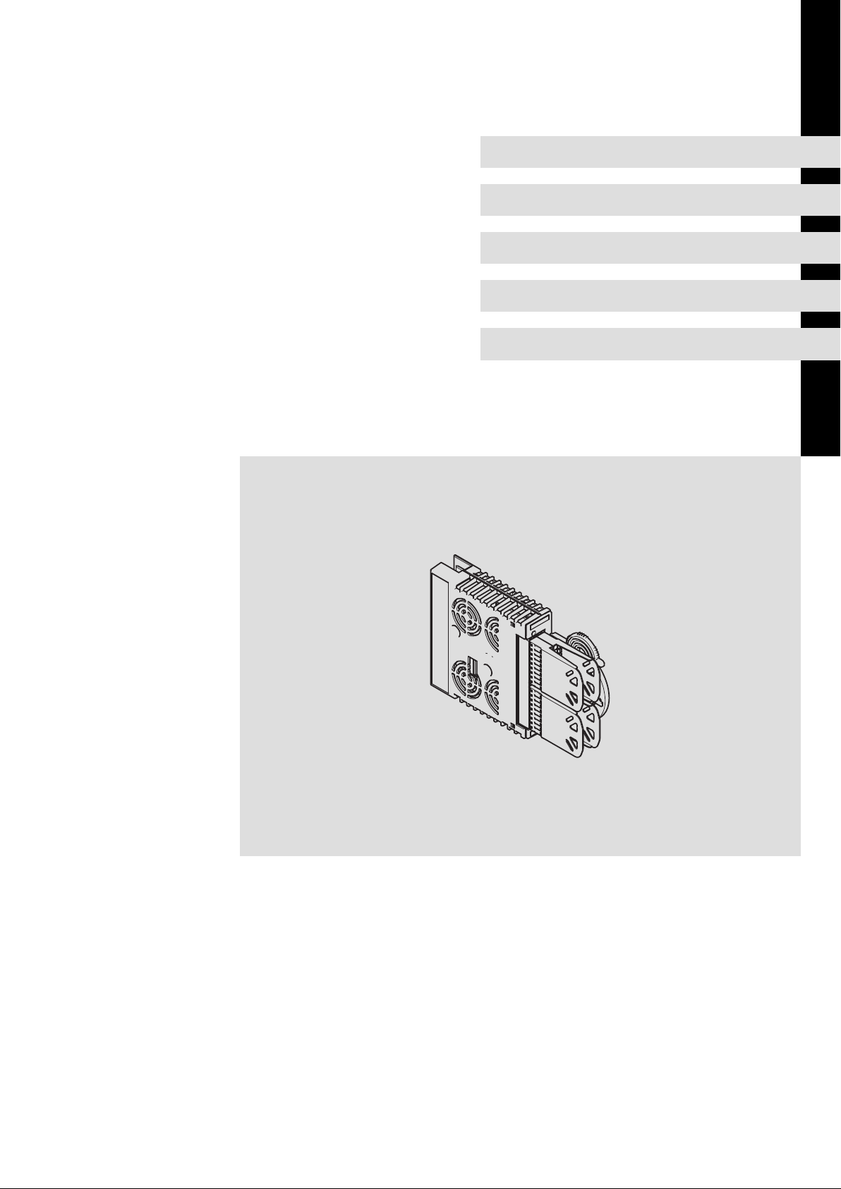
1.2 Device modules
1.2.1 Slot
The slot for the safety modules is marked in the documentation with M4. It is the lowest
slot in the controller (see overview in the documentation of the controller).
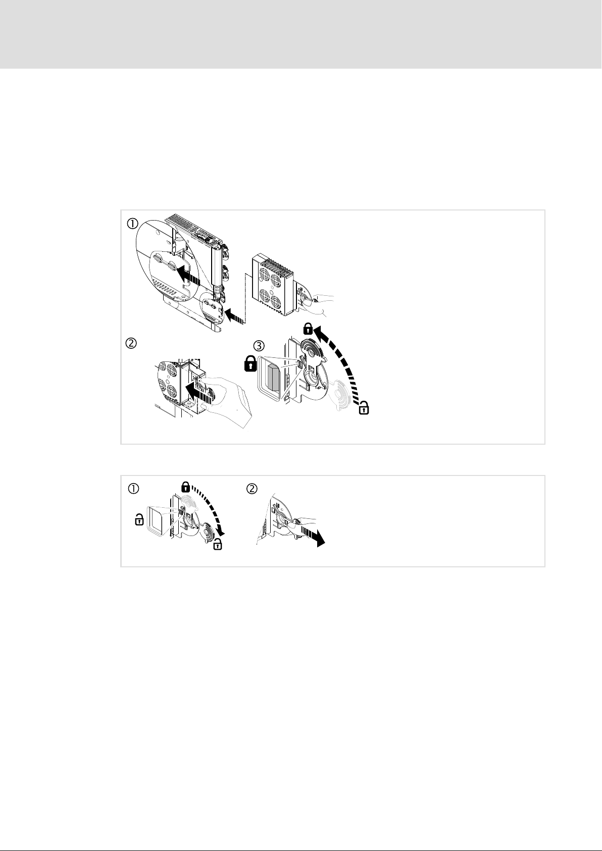
1.2.1.1 Mounting
1.2.1.2 Dismounting
E94AYAX001
E94AYCXX001H
12
EDS94AYAE EN 7.0
Page 13

1.2.1.3 Module exchange
Stop!
Before mounting/dismounting, switch off the supply voltage to prevent
electronic modules from damage.
Every module exchange is detected by the standard device and documented in a logbook.
When a module is replaced by the same type, no restrictions arise. Depending on the
module type it may be necessary to take further measures (e.g. address setting, safe
parameter setting, ...).
When the module is replaced by a different type, the drive is inhibited by the controller. The
inhibit can only be deactivated when the parameter setting of the required safety module
complies with the plugged safety module.
Codes
Safety engineering
Device modules
Slot
1
Parameter: Name: Data type: Index:
C00214 Required safety module
Setting of the expected safety module
l If a safety module deviating from this setting is detected, an error (fault) is caused. The error can only be
removed by mains switching.
Selection list
þ Read access þ Write access o Controller inhibit o PLC-STOP o No transfer o COM o MOT
(Lenze setting bold) Information
1 SM0
2 SM100
4 SM300
5 SM301
UNSIGNED_8 24361d = 5F29
Note!
In case you exchange the module, the address switch must be set identically
to the module to be replaced. Only then the corresponding safe parameter set
can be transferred to the module.
h
EDS94AYAE EN 7.0
13
Page 14
1
M
SMx
PWM
µC
PC
3x
3x
Xx
Safety engineering
Device modules
Function mode of the safety modules
1.2.2 Function mode of the safety modules
C00214
The setting in C00214 must comply with the plug−in safety module type so that the
controller is able to operate.
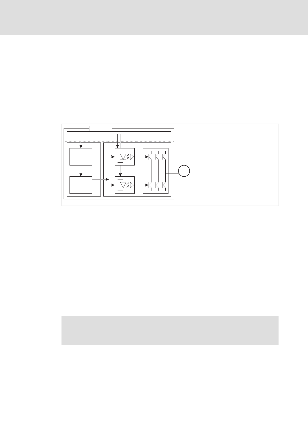
Disconnecting paths
The transmission of the pulse width modulation is safely disconnected by the safety
module. Hence the drivers do not create a rotating field. The motor is safely switched to
torqueless operation (STO).
SSP94SM320
Fig. 1−1 Disconnecting paths of the safety modules
SMx Safety module
xx Input / output terminal
C Control section
mC Microcontroller
PWM Pulse width modulation
P Power section
M Motor
Safety status
When the controller is switched off by the safety module, the controller switches to the
"Safe torque off"device state.
ƒ "Controller in STO state" is entered into the logbook (0x00750003).
ƒ "Safe torque off active" is displayed in C00183.
Fail−safe status
Note!
If internal errors of the safety modules are detected, the motor is safely
switched to torque−free operation (fail−safe status).
14
EDS94AYAE EN 7.0
Page 15
Safety engineering
Device modules
SM301 safety module
1
1.2.3 SM301 safety module
Validity information
These instructions are valid for
SM301 safety module
Type HW SW
E94AYAE from VA from 01.00
Identification
L
'
Type
E94YCEI003C E94AYXX001
E94 A Y A x xx xx nn
Product series
Version
Module identification: Device module
Module type: Safety module
Design
A = SM0
B = SM100
E = SM301
Hardware version
Software version (SM301 only)
Serial number
EDS94AYAE EN 7.0
15
Page 16

1
Safety engineering
Device modules
SM301 safety module
Application range
The use of this module is permissible with standard devices of the 9400 product series from
nameplate designation
Type HW SW
E94AxHExxxx VA 01.49
E94AxPExxxx 2A 02.xx
Safe position and speed detection with a resolver selected as the motor encoder and an
additional position encoder is permissible with SM301 V1.3 and standard devices of the
9400 product series from nameplate designation
Type HW SW
E94AxHExxxx xx 07.xx
E94AxPExxxx 2A 02.xx
Safe position and speed detection with a resolver selected as the motor encoder is
permissible with SM301 V1.4 and standard devices of the 9400 product series from
nameplate designation
Type HW SW
E94AxHExxxx xx 08.xx
E94AxPExxxx 2A 02.xx
The use of this module is permissible with the PROFIBUS communication module from
nameplate designation
Type HW SW
E94AYCPM VB 01.10
This module as of SM301 V1.1 may be used in conjunction with the PROFINET
communication module with the following nameplate data
Type HW SW
E94AYCER VC 00.70
Note!
A safety bus system (PROFIsafe) can only be operated via the upper module
slot (MXI1) of the Servo Drive 9400.
16
EDS94AYAE EN 7.0
Page 17

1.2.3.1 Overview
Functions from SM301 V1.0 onwards
ƒ Safe torque off (STO)
(formerly: safe standstill, protection against unexpected start−up)
ƒ Safe stop 1 (SS1)
ƒ Safe stop 2 (SS2) − see SOS
ƒ Safe stop emergency (SSE)
ƒ Safe operational stop (SOS) − in accordance with EN 61800−5−2: SOS is designed with
speed monitoring
ƒ Safe maximum speed (SMS)
ƒ Safely limited speed 1 (SLS1)
ƒ Safe operation mode selector (OMS)
Safety engineering
Device modules
SM301 safety module
1
ƒ Safe enable switch (ES)
ƒ Safe speed monitor (SSM)
ƒ Safe monitor (output)
ƒ Connection of safety sensors
ƒ Safe parameterisation
ƒ Safety bus connection (PROFIsafe V1)
Additional functions as of SM301 V1.1
ƒ Safely limited speed 2 (SLS2)
ƒ Safely limited speed 3 (SLS3)
ƒ Safely limited speed 4 (SLS4)
ƒ Safe cascading (CAS) via SD−In4/SD−Out1
ƒ Safety bus connection (PROFIsafe V2)
Additional functions from SM301 V1.2
ƒ Parameterisable response time of encoder monitoring
Additional functions from SM301 V1.3
ƒ Safe operational stop (SOS) − compliant with EN 61800−5−2: SOS is designed with
position monitoring
EDS94AYAE EN 7.0
ƒ Safe direction (SDI)
ƒ Safe speed measurement and position detection with resolver using a motor
encoder and an additional position encoder (two−encoder−concept)
Additional functions as of SM301 V1.4
ƒ Safely limited increment (SLI)
ƒ Safely monitored brake ramp for SS1/SS2
ƒ Safe speed and position detection with resolver selected as the motor encoder
17
Page 18

1
Safety engineering
Device modules
SM301 safety module
Motor−encoder combinations
Drive systems with Servo Drives 9400 and safety module SM301 provide speed−dependent
safety functions for safe speed monitoring and/or safe relative−position monitoring.
Observe permissible motor−encoder combinations during configuration.
ƒ Possible speed−dependent safety functions with safety module SM301:
– Safe stop 1 (SS1)
– Safe operational stop (SOS)
– Safely limited speed (SLS)
– Safe maximum speed (SMS)
– Safe direction (SDI)
– Safe speed monitor (SSM)
– Safely limited increment (SLI)
ƒ Permissible motor−encoder combinations for these functions:
Synchronous
servo motors
MCS 06 ... 19
MDXKS 56 / 71
Asynchronous
servo motors
MCA 10 ... 26
MQA 20 ... 26
Three−phase
asynchronous
motors
MDxMA063−xx ...
MDxMA225−xx
MHxMA080−xx ...
MHxMA225−xx
MFxMA063−xx ...
MFxMA132−xx
Encoder
Type Product key
Sin/cos absolute value, single−turn AS1024−8V−K2
Sin/cos absolute value, multi−turn AM1024−8V−K2
Resolver RV03 PL e / SIL 3
Encoder
Type Product key
Sin/cos incremental IG1024−5V−V3
Resolver RV03
Encoder
Type Product key
Sin/cos incremental
IG2048−5V−V3
IG2048−5V−V2 PL d / SIL 2
Safe speed monitoring with SM301
Single−encoder
concept
Two−encoder concept Up to PL e / SIL 3
Safe speed monitoring with SM301
Single−encoder
concept
Two−encoder concept Up to PL e / SIL 3
Safe speed monitoring with SM301
Single−encoder
concept
Two−encoder
concept
PL d / SIL 2
PL e / SIL 3
PL e / SIL 3
Up to PL e / SIL 3
18
A "two−encoder concept" includes e.g. a resolver as motor encoder and, at the same time,
an absolute value encoder (sin/cos), an incremental encoder (TTL), or digital encoder
(SSI/bus) as position encoder on the machine.
In the case of the "2−encoder concept", the achievable risk mitigation (PL/SIL) depends on
the suitability of the encoders used.
Note!
If feedback systems for safety functions are used, the manufacturer’s
documentation must be observed!
EDS94AYAE EN 7.0
Page 19

Safety engineering
Device modules
SM301 safety module
Compatibility
Compatibility of SM301/SM300
The SM301 safety module is compatible with the SM300. The controller needs to be
adapted since the safe parameter set is required. Observe the following:
ƒ The GSE file can be used.
ƒ The PROFIsafe bits that are not used with SM300 must be suppressed in the SM301,
since unset bits would activate safety functions.
ƒ Speed−dependent functions cannot be used.
Compatibility of different SM301 versions
Replacement of an SM301 by an SM301 with a higher firmware version (SW):
ƒ Every SM301 can be used with a safe parameter set of an elder firmware version
without any changes.
ƒ The safe parameter set including CRC in the memory module of the drive is not
changed when the parameter set from the memory module is accepted.
1
ƒ The CE Declaration of Conformity remains valid.
ƒ The replacement of the safety module by an equivalent module is ensured. Thus,
there is no need for spare part stockage of SM301 safety modules with elder
firmware versions.
ƒ Safe parameter sets of the "SM301 safety module" component can be loaded into
an SM301 with a higher firmware version without any changes.
– Extended functionalities of the newer firmware version cannot be selected and
executed.
The safe parameter set of an SM301 with a newer firmware version cannot be loaded into
an SM301 with an elder firmware version.
1.2.3.2 Safety category
The implemented safety functions meet the requirements of the standards:
ƒ Control category 3 according to EN ISO 13849−1
In order to comply with category 3, the external wiring and cable monitoring must also
meet the requirements of category 3.
ƒ Performance Level (PL) "e" according to EN ISO 13849−1
EDS94AYAE EN 7.0
19
Page 20
1
Safety engineering
Device modules
SM301 safety module
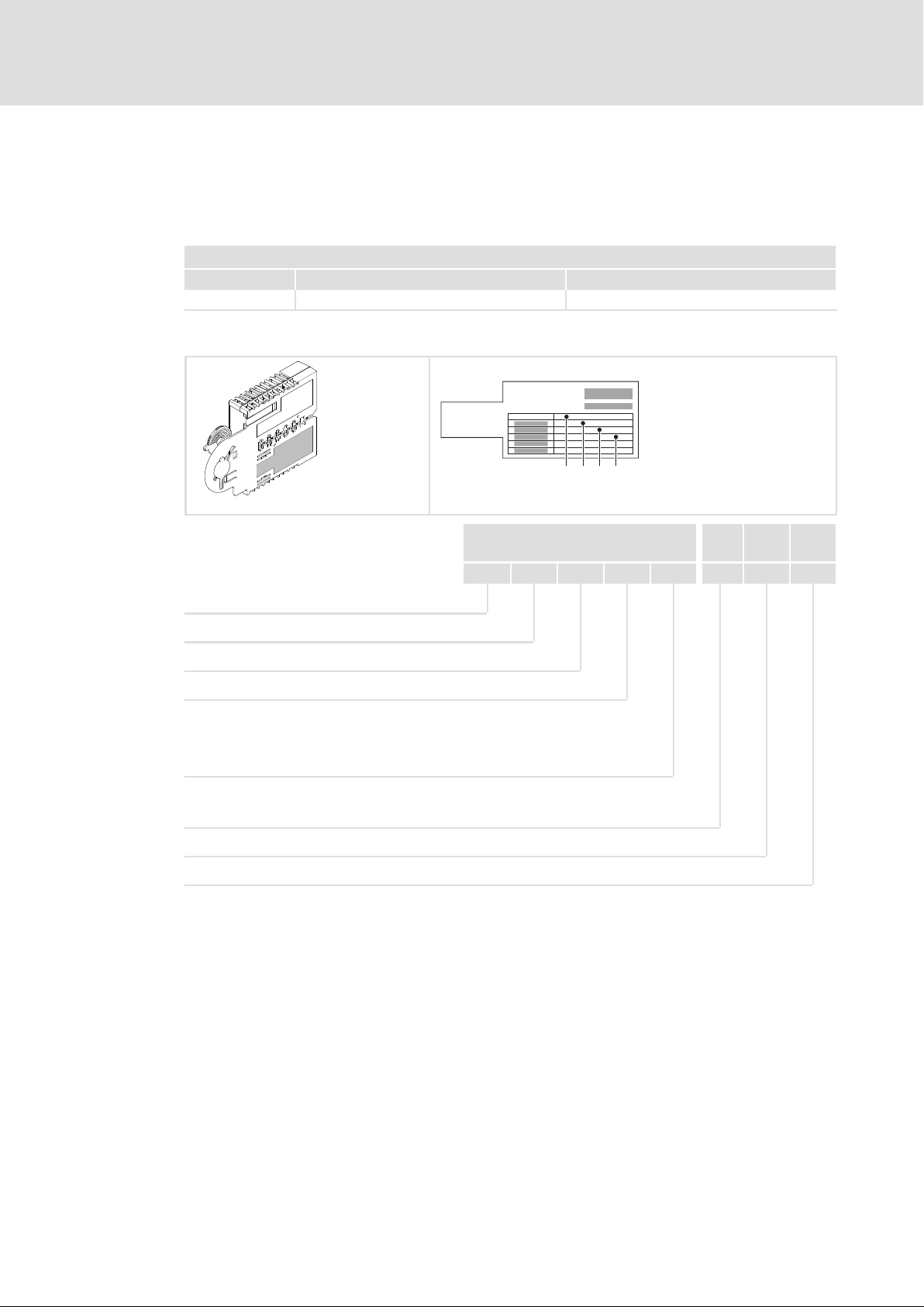
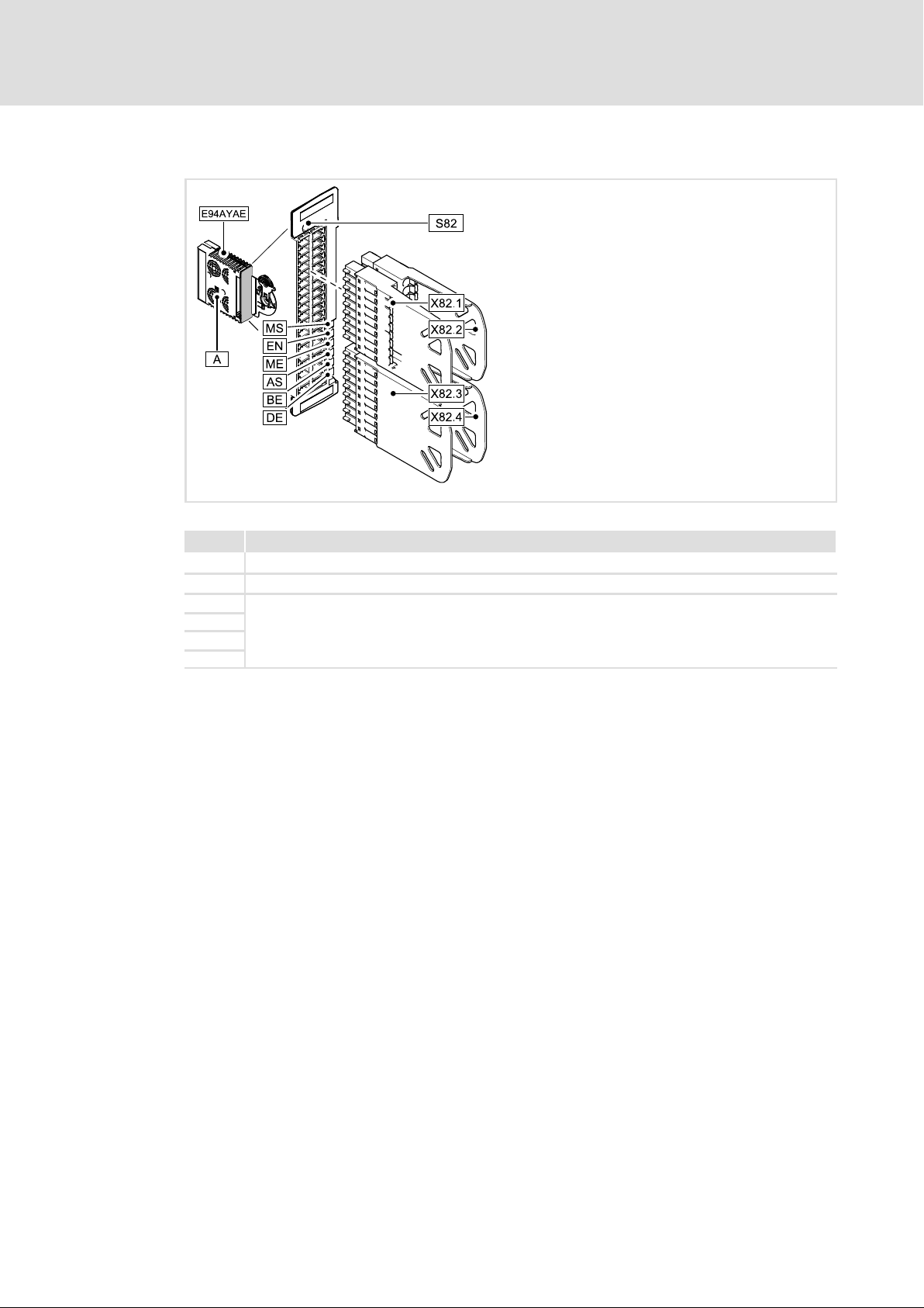
1.2.3.3 Elements of the module
Fig. 1−2 Module view
SSP94SM321
Pos. Description
Safety address switch (in the left part of the housing)
S82 Module switch for parameter set adoption from the memory module
X82.1
X82.2
X82.3
X82.4
Plug−in terminal strips for input and output signals
20
EDS94AYAE EN 7.0
Page 21

Displays
Pos. Colour State Description
On
Blinking
MS
(Module State)
EN
(Enable)
ME
(Module Error)
AS
(Acknowledge Stop)
BE
(Bus Error)
DE
(Drive Error)
Blinking: on/off every 0.5 s Flashing: on/off every 0.1/0.9 s
Green
Yellow
Red
Yellow
Red
Red
Flashing
Off
On
Off
On
Blinking
Flashing
Off Error−free operation
On
Blinking
Flashing
Off No stop function active
On
Blinking
Off Safety bus: error−free operation.
On
Off
Drive−based safety has initialised without a fault.
Drive−based safety has initialised without a fault. Internal
communication to the standard device is not possible.
Drive−based safety is in service status.
For exiting, parameterise the drive−based safety.
Drive−based safety is not initialised.
Acknowledgement is not possible.
Controller enabled
Non−safe display "STO"
System error
Trouble
Warning
Request of an acknowledgement for the restart or the
parameter set adoption
SS1/STO active
SS2/SOS active
Safety bus error:
l Communication is not possible.
l Acknowledgement is possible.
Safety bus error: no valid configuration.
Drive−based safety is not accepted by the standard device
(see notes in the instructions for the standard device).
Drive−based safety is correctly recognised by the standard
device.
Safety engineering
Device modules
SM301 safety module
1
EDS94AYAE EN 7.0
21
Page 22
1
Safety engineering
Device modules
SM301 safety module
Terminal assignment
Danger!
Danger to life through improper installation
Improper installation of the safety engineering systems can cause
anuncontrolled starting action of the drives.
Possible consequences:
ƒ Death or severe injuries
Protective measures:
Total cable length between X82 and its connected components (e.g. sensors,
devices, ...) > 3 m:
ƒ Up to HW version 1A, a shielded laying system must be used for the cable
between X82 and its connected components:
– The shield must at least cover the shield connection at the installation
backplane.
– The shield should also cover the connected component if possible.
ƒ From HW version 1A onwards, unshielded wiring is permissible.
Total cable length between X82 and its connected components (e.g. sensors,
devices, ...) < 3 m:
ƒ Unshielded wiring is permissible.
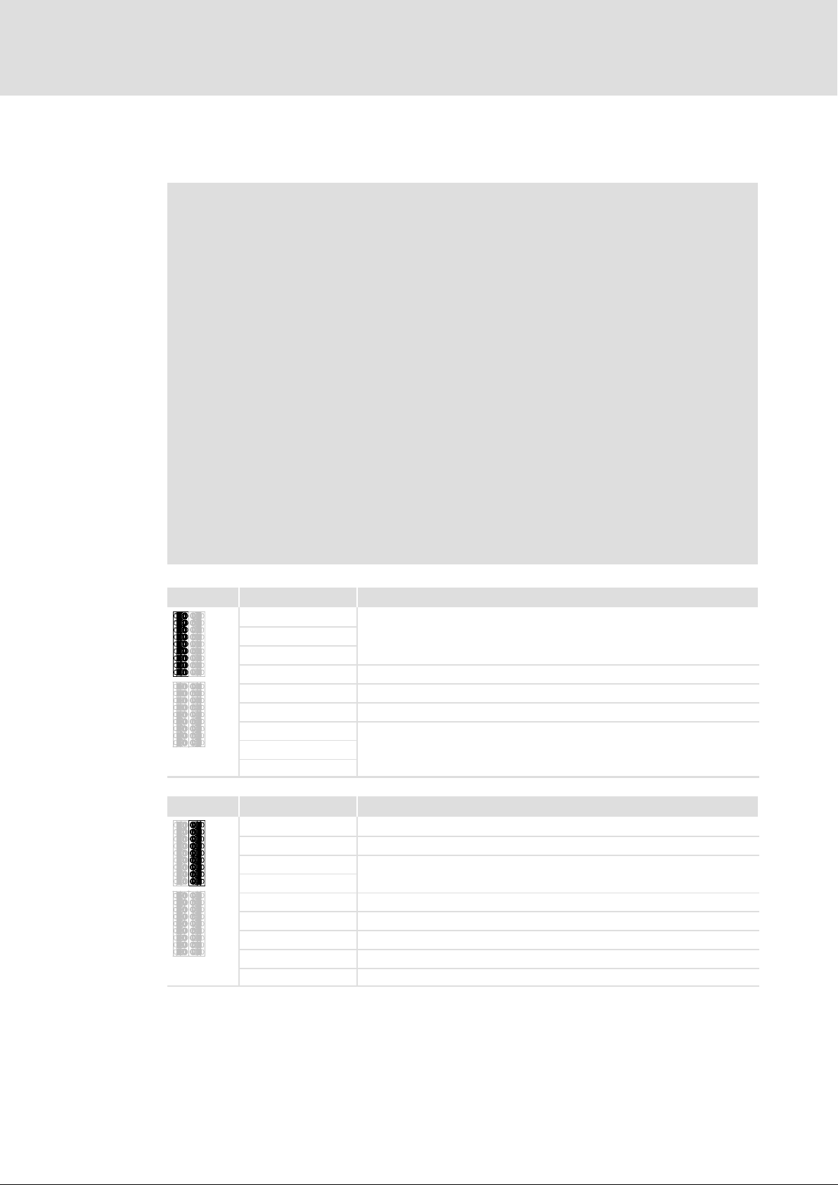
X82.1 Labelling Description
This part of the terminal strip is not assigned.
GO
O1B
O1A
X82.2 Labelling Description
−
+
GIR
RI1
GO
24O
AIE
CLA Clock output for passive sensors, channel A (Clock A)
CLB Clock output for passive sensors, channel B (Clock B)
GND SD−Out1
Safe monitor SD−Out1, channel B
Safe monitor SD−Out1, channel A
This part of the terminal strip is not assigned.
GND external supply
+24 V external supply via a safely separated power supply unit (SELV/PELV)
This part of the terminal strip is reserved.
GND 24O
+24 V external supply for the safe monitor SD−Out1 (SELV/PELV)
Error acknowledgement input ("Acknowledge In Error")
22
EDS94AYAE EN 7.0
Page 23
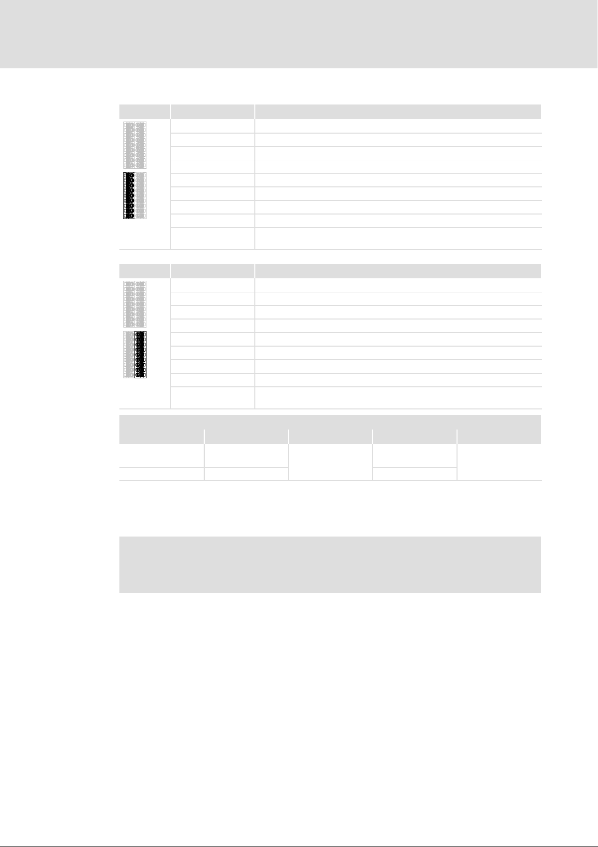
X82.3 Labelling Description
GCL
GI2
I2B
I2A
GCL
GI1
I1B
I1A
AIS
X82.4 Labelling Description
GCL
GI4
I4B
I4A
GCL
GI3
I3B
I3A
AIS
GND clock output
GND SD−In2
Sensor input SD−In2, channel B
Sensor input SD−In2, channel A
GND clock output
GND SD−In1
Sensor input SD−In1, channel B
Sensor input SD−In1, channel A
Restart acknowledgement input ("Acknowledge In Stop", 1−channel,
bridged to X82.4/AIS)
GND clock output
GND SD−In4
Sensor input SD−In4, channel B
Sensor input SD−In4, channel A
GND clock output
GND SD−In3
Sensor input SD−In3, channel B
Sensor input SD−In3, channel A
Restart acknowledgement input ("Acknowledge In Stop", 1−channel,
bridged to X82.3/AIS)
Safety engineering
Device modules
SM301 safety module
1
Cable cross−sections and tightening torques
Type [mm2] [Nm] AWG [lb−in]
Wire end ferrule,
insulated
Rigid
Stripping length or contact length: 9 mm
0.25 ... 0.75
0.14 ... 1.5 26 ... 16
Spring terminal
24 ... 18
Spring terminal
Insulated wire end ferrules according to DIN 46228, part 4, 0.5 mm2 or 0.75 mm2 − length
L1 = 10 mm can be used.
Note!
Provide for a sufficient strain relief, so that the terminals are not pulled from
the plug connectors, in particular when you use rigid cables.
EDS94AYAE EN 7.0
23
Page 24
1
Safety engineering
Device modules
SM301 safety module
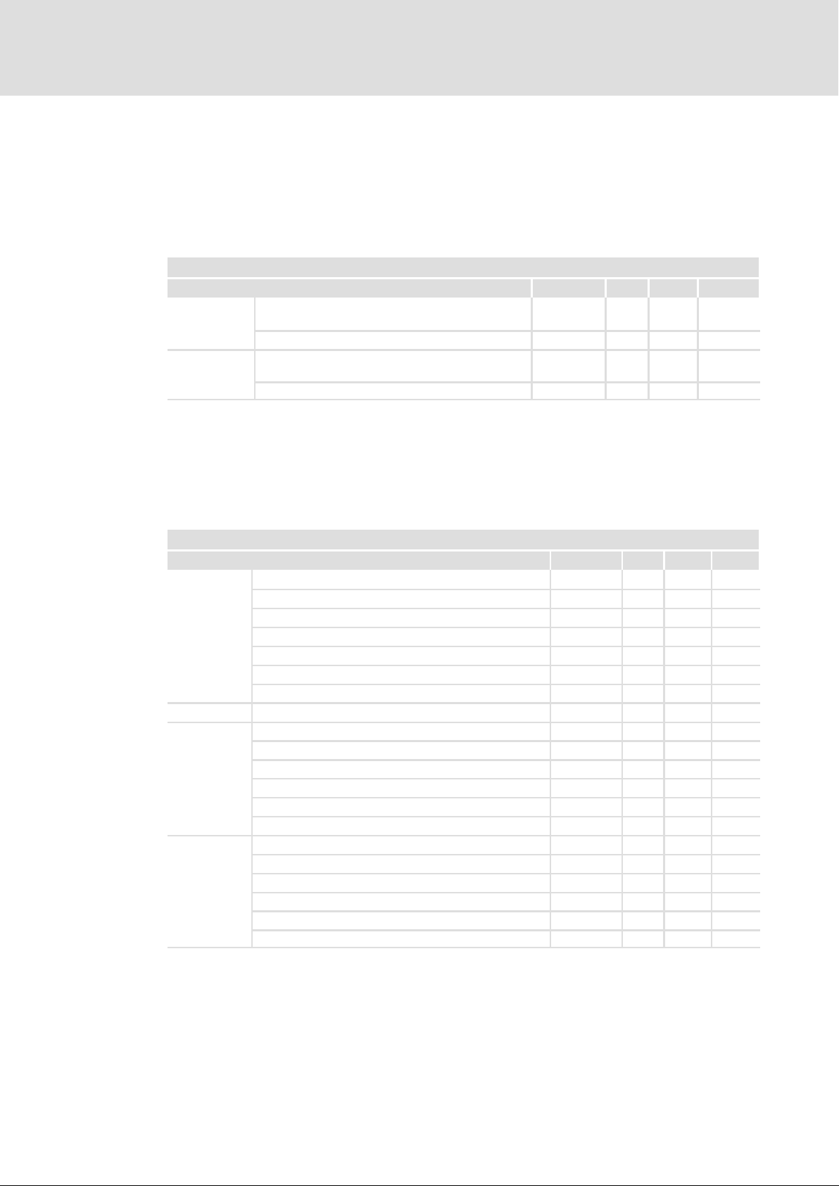
1.2.3.4 Technical data
24 V supply
The module and the safe output must be supplied with 24 V from safely separated power
supply units. If electrical isolation is required, separate voltage supply lines must be used.
Detailed features of the 24−V supply
Terminal Specification [Unit] min. typ. max.
+, −
24O, GO
If the voltage of the SELV/PELV power supply unit can exceed 30 V in the event of an error,
provide for an external fuse ( 1.1.8).
Supply voltage of the module via a safely separated
power supply unit (SELV/PELV)
Input current [mA] 350
Supply voltage of the safe output via a safely
separated power supply unit (SELV/PELV)
Input current [mA] 1100
[V] 19,2 24 30
[V] 18 24 30
Inputs and output
The inputs and the output are isolated and designed for a low−voltage supply of 24 V DC.
The digital inputs are protected against polarity reversal.
Detailed features of the safe inputs and the safe output
Terminal Specification [Unit] min. typ. max.
I1A, I1B
I2A, I2B
I3A, I3B
I4A, I4B
AIE, AIS
AIE, AIS Input delay (operating time) s 0.3 10
CLA, CLB
O1A, O1B
Tab. 1−1 Technical data
PLC input, IEC−61131−2, 24 V, type 1
Low signal input voltage
Input current at low signal mA 15
High signal input voltage
Input current at high signal mA 2 15
Input capacitance
Repetition rate of the test pulses
PLC output, IEC−61131−2, 24 V DC, 50 mA
Low signal output voltage
High signal output voltage
Output current
Cable capacity
Cable resistance of a passive sensor
PLC output, IEC−61131−2, 24 V DC
Low signal output voltage
High signal output voltage
Output current
Cable capacity
Cable resistance
V −3 0 5
V 15 24 30
nF 3.5
ms 50
V 0 0.8
V 17 24 30
mA 60
nF 100
W 200
V 0 0.8
V 17 24 30
mA 500
nF 100
W 200
24
The chapter "Response times" must be observed as well ( 1.8).
EDS94AYAE EN 7.0
Page 25

1.2.3.5 Example circuit
SM301
E94AYAE
X82.1 X82.2
-
+
GO
O1B
O1A
GO
24O
AIE
CLA
CLB
Safety engineering
1
Device modules
SM301 safety module
24 V ext.
GCL
GI2
I2B
I2A
S2
S1
K
GCL
GI1
I1B
I1A
AIS
X82.3
Fig. 1−3 Wiring example
E94AYAE SM301 safety module
S1
S2
S3 higher−level safety control (active sensor)
S4 lightgrid (active sensor)
24 V ext. 24−V voltage supply of the module (SELV/PELV)
24−V voltage supply of the output (SELV/PELV)
safe output to higher−level safety control
K to AIS of the next module
GCL
GI4
I4B
I4A
GCL
GI3
I3B
I3A
AIS
S4
S3
X82.4
passive sensor with channel A and B
SSP94SM360
EDS94AYAE EN 7.0
25
Page 26

1
1.2.3.6 Commissioning
Safety engineering
Device modules
SM301 safety module
ƒ For commissioning and safe parameter setting, the Lenze »Engineer« PC
software from version 1.4 must be used.
If you select the safety module in the Project view, various tabs are available in the
Operating range via which the safety module can be parameterised. In all other
program parts the parameters of the safety module can only be read. Thus, the write
access of these parameters (codes) is marked with .
ƒ Settings in or at the module:
– Safety address
– Safe parameter setting of the functions to be used
ƒ Required settings in the standard device:
– C00214, type of safety module
– Implementation of the SM301 into the drive application by evaluating the control
information and status information.
ƒ During commissioning and after the replacement of a module it is vital to check the
safety function. Additional information contains the "Acceptance" chapter. ( 110).
26
EDS94AYAE EN 7.0
Page 27
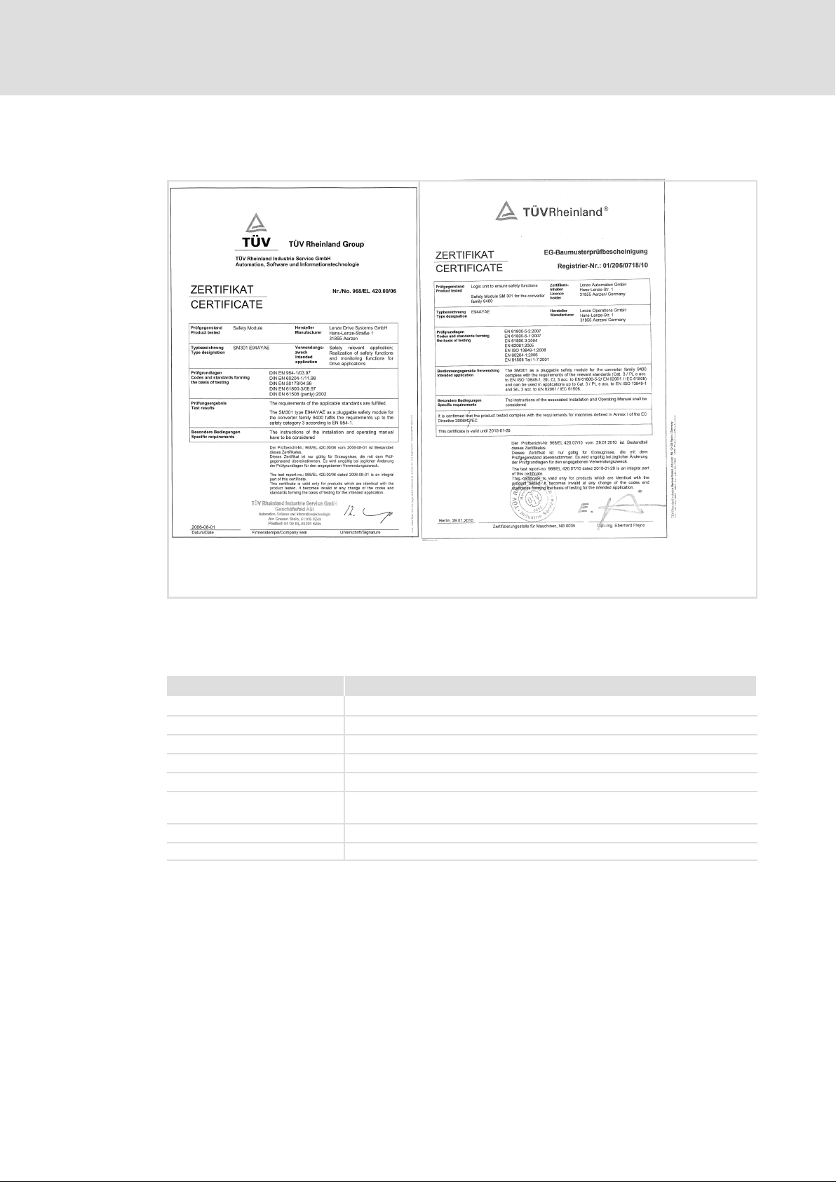
1.2.3.7 Test certificate
Safety engineering
Device modules
SM301 safety module
1
SSP94TUEV3 _2010
Fig. 1−4 TÜV Certificate
The type test was carried out by ’TÜV Rheinland (Group)’ and confirmed with a certificate.
ƒ SM301 V1.0
Contents Specifications
Test institute TÜV Rheinland Industrie Service GmbH, ASI range
Test report 968/EL 420.00/06
Test fundamentals EN 954−1, EN 60204−1, EN 50178, EN 61800−3, IEC 61508 Part 1−7
Object to be examined SM301, type E94AYAE VA1.0x of the 9400 Servo Drives series
Test result The module meets the requirements according to EN 954−1, category 3.
Special conditions The safety instructions in the corresponding user documentation must be
Place of issue Cologne
Issue date 01.08.2006
observed.
EDS94AYAE EN 7.0
27
Page 28

1
Safety engineering
Device modules
SM301 safety module
ƒ from SM301 V1.1
Contents Specifications
Test institute TÜV Rheinland Industrie Service GmbH, ASI range
Test report 968/EL 420.03/07
Test fundamentals EN 954−1, EN 60204−1, EN 50178, EN 61800−3, EN 61508 Part 1−7,
Object to be examined SM301, type E94AYAE VB1.1x of the 9400 Servo Drives series
Test result The module meets the requirements according to
Special conditions The safety instructions in the corresponding user documentation must be
Place of issue Cologne
Issue date 08.05.2007
ƒ from SM301 V1.2
EN ISO 13849−1, EN 62061
l EN 954−1, category 3
l EN 61508, SIL 3
l EN ISO 13849−1, PL e
observed.
Contents Specifications
Test institute TÜV Rheinland Industrie Service GmbH, ASI range
Test report 968/EL 420.04/07
Test fundamentals EN 954−1, EN 60204−1, EN 50178, EN 61800−3, EN 61508 Part 1−7,
Object to be examined SM301, type E94AYAE of the Servo Drives 9400 series
Test result The module meets the requirements according to
Special conditions The safety instructions in the corresponding user documentation must be
Place of issue Cologne
Issue date 18.10.2007
EN ISO 13849−1, EN 62061
l EN 954−1, category 3
l EN 61508, SIL 3
l EN ISO 13849−1, category 3/PL e
observed.
28
EDS94AYAE EN 7.0
Page 29

Safety engineering
Device modules
SM301 safety module
ƒ from SM301 V1.3
Contents Specifications
Test institute TÜV Rheinland Industrie Service GmbH, ASI range
Test report 968/EL 420.07/10
Certification body NB 0035
Registration no. 01/205/0718/10
Test fundamentals EN 60204−1, EN 61800−3, EN 61508 Part 1−7, EN ISO 13849−1, EN 62061,
EN 61800−5−2, EN 61800−5−1
Object to be examined SM301, type E94AYAE of the Servo Drives 9400 series
Test result The module meets the requirements according to
l EN 61508, SIL 3
l EN ISO 13849−1, category 3/PL e
Special conditions The safety instructions in the corresponding user documentation must be
observed.
Place of issue Berlin
Issue date 29.01.2010
Valid until 29.01.2015
1
ƒ from SM301 V1.4
Contents Specifications
Test institute TÜV Rheinland Industrie Service GmbH, ASI range
Test report 968/EL 420.08/10
Test fundamentals EN 60204−1, EN 61800−3, EN 61508 Part 1−7, EN ISO 13849−1, EN 62061,
Object to be examined SM301, type E94AYAE of the Servo Drives 9400 series
Test result The module meets the requirements according to
Special conditions The safety instructions in the corresponding user documentation must be
Place of issue Cologne
Issue date 11.10.2010
EN 61800−5−2, EN 61800−5−1
l EN 61508, SIL 3
l EN ISO 13849−1, category 3/PL e
observed.
EDS94AYAE EN 7.0
29
Page 30

1
Safety engineering
Device modules
Safe inputs
1.2.4 Safe inputs
1.2.4.1 General
The following applies to the sensors at the SM301 V1.0:
ƒ Sensor type and sensor function can be parameterised in C15030, C15031 and
C15032.
ƒ A local evaluation is executed if corresponding parameters are set.
ƒ If a safety bus is activated, the sensor signals are sent as status information to the
higher−level control.
ƒ Deactivated sensor inputs must not be connected. The status of a non−connected
input is in the OFF state.
ƒ If a signal is detected at deactivated sensor inputs during initialisation, the drive
remains inhibited (STO).
ƒ Faulty inputs are assessed as OFF state.
Additional conditions from SM301 V1.1 onwards:
ƒ With active cascading in C15035 the SD−In4 input cannot be used freely anymore.
Codes
Parameter: Name: Data type: Index:
C15030 SD-In sensor type
Configuration of the sensor types which are connected to the safe inputs.
Selection list (Lenze setting bold) Information
0 Input deactivated
1 Passive sensor
2 Active sensor
Subcodes Information
C15030/1 SD-In1 sensor type
C15030/2 SD-In2 sensor type
C15030/3 SD-In3 sensor type
C15030/4 SD-In4 sensor type
þ Read access Write access o Controller inhibit o PLC-STOP o No transfer
C15031 SD-In sensor function
Function configuration of the safe inputs.
l The "operation mode selector" and "enable switch" functions may only be assigned to one of the four safe
inputs.
Selection list
Subcodes Information
C15031/1 SD-In1 sensor function
C15031/2 SD-In2 sensor function
C15031/3 SD-In3 sensor function
C15031/4 SD-In4 sensor function
þ Read access Write access o Controller inhibit o PLC-STOP o No transfer
(Lenze setting printed in bold) Information
0 Free assignment Safety function set in C15032
1 Emergency stop Safe stop emergency function (SSE)
2 Operation mode selector Safe operation mode selector (OMS)
3 Enable switch Safe enable switch (ES)
UNSIGNED_8 9545d = 2549
UNSIGNED_8 9544d = 2548
h
h
30
EDS94AYAE EN 7.0
Page 31

Safety engineering
Device modules
Safe inputs
C15032 SD-In free assignment
Assignment of a safety function to a safe input.
l Only possible if the "free assignment" sensor function is set for the safe input in C15031.
Selection list
Subcodes Information
C15032/1 Free assignment SD-In1
C15032/2 Free assignment SD-In2
C15032/3 Free assignment SD-In3
C15032/4 Free assignment SD-In4
þ Read access Write access o Controller inhibit o PLC-STOP o No transfer
C15205 SSE: Safe stop emergency function
Selection of the stop function for emergency stop
Selection list (Lenze setting printed in bold) Information
þ Read access Write access o Controller inhibit o PLC-STOP o No transfer
(Lenze setting printed in bold) Information
0 STO Safe torque off
1 SS1 Safe stop 1
2 SS2 Safe stop 2
3 SLS1 Safely limited speed 1
4 SLS2 Safely limited speed 2 (from SM301 V1.1)
5 SLS3 Safely limited speed 3 (from SM301 V1.1)
6 SLS4 Safely limited speed 4 (from SM301 V1.1)
7 SDIpos Safe positive direction (from SM301 V1.3)
8 SDIneg Safe negative direction (from SM301 V1.3)
9 No function No (local) safety function assigned.
l Functional test and monitoring of the discrepancy
time are active.
l The input status is transferred to the control via the
safety bus (if parameterised).
0 STO Safe torque off
1 SS1 Safe stop 1
UNSIGNED_8 9543d = 2547
UNSIGNED_8 9370d = 249A
1
Index:Data type:Name:Parameter:
h
h
EDS94AYAE EN 7.0
31
Page 32

1
Safety engineering
Device modules
Safe inputs
Specification
passive active
Discrepancy time parameterisable 0 ... 30000 ms (increment: 2 ms)
Input delay parameterisable 0 ... 100 ms (increment: 2 ms)
Input filter time for test pulses fixed 2 ms
Repetition rate of the test pulses is determined by the clock outputs
CLA and CLB
Error response Sensor input is assessed as OFF state.
Acknowledgement via safety bus or AIE input
Tab. 1−2 Specification of sensor connections
Sensor type
> 50 ms
Explanations
ƒ Discrepancy time
Maximum time in which both channels of a safe input may have non−equivalent states
without the safety engineering causing an error response.
ƒ Input delay
Time between the recognition of the signal change and the effective evaluation of an
input signal. As a result, multiple and short signal changes due to contact bounce of the
components are not taken into account.
ƒ Input filter time
Time in which the interference pulses and test pulses are not detected by e.g. active
sensors that are switched on.
The input delay time and the time of the input filters influence the response time. More
information can be found in the "Response times" chapter ( 107).
Codes
Parameter: Name: Data type: Index:
C15033 SD-In discrepancy time
Maximum time in which both channels of a safe input may have non−equivalent states without the safety
engineering causing an error response.
Setting range (min. value | unit | max. value) Information
0 MS 30000 Lenze: 10, increment: 2 ms
Subcodes Information
C15033/1 SD-In1 discrepancy time
C15033/2 SD-In2 discrepancy time
C15033/3 SD-In3 discrepancy time
C15033/4 SD-In4 discrepancy time
þ Read access Write access o Controller inhibit o PLC-STOP o No transfer
UNSIGNED_16 9542d = 2546
h
32
EDS94AYAE EN 7.0
Page 33

Safety engineering
Device modules
Safe inputs
Index:Data type:Name:Parameter:
C15034 SD-In input delay
Time between the recognition of the signal change and the effective evaluation of an input signal. As a result,
multiple and short signal changes due to contact bounce of the components are not taken into account.
Setting range
0 MS 100 Lenze: 0, increment: 2 ms
Subcodes Information
C15034/1 Input delay SD-In1
C15034/2 Input delay SD-In2
C15034/3 Input delay SD-In3
C15034/4 Input delay SD-In4
þ Read access Write access o Controller inhibit o PLC-STOP o No transfer
(min. value | unit | max. value) Information
UNSIGNED_8 9541d = 2545
Contact function test
Note!
Make sure that an internal contact function test is carried out at the safe
inputs:
Safe input in the ON state
ƒ A LOW level at one channel puts the input in the OFF state. The discrepancy
monitoring starts simultaneously.
ƒ A LOW level must be detected at both channels within the discrepancy time,
otherwise a discrepancy error will be reported.
ƒ To be able to acknowledge the discrepancy error, a LOW level must be
detected before at both channels.
Safe input in the OFF state
ƒ A HIGH level at one channel starts the discrepancy monitoring.
ƒ A HIGH level must be detected at both channels within the discrepancy
time, otherwise a discrepancy error will be reported.
ƒ To be able to acknowledge the discrepancy error, a HIGH level must be
detected before at both channels.
1
h
EDS94AYAE EN 7.0
ON state
Value of safe input:
ON state
Switch both channels
to ON state
Discrepancy monitoring Discrepancy monitoring
Value of safe input:
OFF state
One channel in
ON state
OFF state
Value of safe input:
OFF state
One channel in
OFF state
Value of safe input:
OFF state
Switch both channels
to OFF state
33
Page 34

1
Safety engineering
Device modules
Safe inputs
SSP94SM355
Fig. 1−5 Status behaviour − contact function test
A
B
C
D
Fig. 1−6 Contact function test − error−free input signals
A
B
C
D
AIE
Fig. 1−7 Contact function test − faulty input signals
A, B Safe input, channel A and channel B
C Internal valuation of the safe input
D Discrepancy monitoring
AIE Fault acknowledgement
Discrepancy monitoring active
Discrepancy monitoring − time−out
Fault acknowledgement impermissible
Fault acknowledgement permissible
SSP94SM358_1
SSP94SM358_2
34
EDS94AYAE EN 7.0
Page 35

1.2.4.2 Connection of passive sensors
The safe sensor inputs I1A ... I4B are suitable for equivalently switching passive sensors.
To monitor passive sensors according to EN ISO 13849−1, cat. 3, the clock outputs CLA and
CLB must be wired. Please observe the following:
ƒ The clock outputs are only suitable for monitoring the passive sensors.
ƒ Always connect ...
– ... CLA to IxA (channel A of the sensor input) via the sensor.
– ... CLA to IxB (channel B of the sensor input) via the sensor.
– ... GCL with GIx of the sensor input.
ƒ The sensor inputs are tested cyclically through short LOW operation.
– The A and B channels are tested at different times in cycles of approx. 2 s, with
test pulses of < 1 ms.
These errors are detected:
Safety engineering
Device modules
Safe inputs
1
ƒ Short circuit to supply voltage.
ƒ Short circuit between the input signals when different clock outputs are used.
ƒ Non−equivalent input signals after the discrepancy time.
These errors are not detected:
ƒ Short circuit between the input signals when the same clock outputs are used.
Avoid unrecognisable errors by the installation, e.g. by separated cable routing.
V
CC
CLA
CLB
GCL
GI2
I2B
SM30x
E94AYAx
S2
û
û
I2A
GCL
GI1
I1B
EDS94AYAE EN 7.0
S1
Fig. 1−8 Ways to detect errors
û Unrecognisable errors
I1A
SSP94SM351
35
Page 36

1
Safety engineering
Device modules
Safe inputs
1.2.4.3 Connection of active sensors
The safe sensor inputs I1A ... I4B are suitable for active sensors.
PN−switched input signals are permissible.
The line monitoring must comply with the requirements of the category 3. Drive−based
safety does not provide for line monitoring.
These errors are detected:
ƒ Non−equivalent input signals after the discrepancy time.
1.2.4.4 Example circuits
IxA
IxB
GxI
SM...S
Fig. 1−9 Example circuit − active sensor
P
M
Fig. 1−10 Functional example of PN−switching sensor
IxA
IxB
GxI
SM...S
S Sensor
P Positive path
M Negative path
SSP94SM352
SSP94SM352
36
EDS94AYAE EN 7.0
Page 37

Safety engineering
Device modules
Safe output
1
1.2.5 Safe output
1.2.5.1 General
Via the safe output O1A/O1B information can be output to a higher−level unit (e.g. safety
PLC) or external switching elements (actuators) can be controlled.
The feedback output is designed in a potential−free fashion. If electrical isolation is
required, a separate supply line must be used.
ƒ The status of the safe output is controlled via two ways:
– directly from the safety module (parameter setting required)
– via the PROFIsafe output data
ƒ The safe output is PP switching, i.e. two plus channels are switched.
ƒ The safe output in ON state is cyclically tested by quick LOW switching.
– The A and B channels are tested at different times in cycles of approx. 2 s, with
test pulses of < 1 ms.
– When selecting the downstream control elements, ensure that the test pulses will
not be detected as LOW signal.
These errors will be detected and set the output to OFF state:
ƒ Short circuit to supply voltage.
ƒ In the ON state: Short circuit between the output signals.
ƒ IN the OFF state: Missing 24−V supply voltage at the terminal 24O is detected as
"Stuck−at−Low" error.
These errors are not detected:
ƒ In the OFF state: short circuit between the output signals.
The output can be assigned multiple feedback information by parameter setting:
ƒ Status of the safety function
ƒ Information on error responses
The code C15060 contains information on the status of the feedback output.
Additional conditions for SM301 from version VB 1.1 onwards:
ƒ With active cascading in C15035 the SD−Out1 output cannot be used freely
anymore.
EDS94AYAE EN 7.0
37
Page 38

1
Safety engineering
Device modules
Safe output
Codes
Parameter: Name: Data type: Index:
C15051 SD-Out condition
Bit coded selection of the conditions for switching the safe output.
Value is bit coded:
Bit 0 STO active
Bit 1 STO active neg. logic
Bit 2 SS1 active
Bit 3 SS1 active neg. logic
Bit 4 SS2 active
Bit 5 SS2 active neg. logic
Bit 6 SLS1 active
Bit 7 SLS1 active neg. logic
Bit 8 SLS2 active
Bit 9 SLS2 active neg. logic
Bit 10 SLS3 active
Bit 11 SLS3 active neg. logic
Bit 12 SLS4 active
Bit 13 SLS4 active neg. logic
Bit 14 SDIpos is active
Bit 15 SDIpos active neg. logic
Bit 16 SDIneg is active
Bit 17 SDIneg active neg. logic
Bit 18 ES active
Bit 19 ES active neg. logic
Bit 20 SLI is active
Bit 21 SLI active neg. logic
Bit 22 OMS
Bit 23 OMS neg. logic
Bit 24 Reserved
...
Bit 31 Reserved
Subcodes Information
C15051/1 SD-Out1 switching condition
þ Read access Write access o Controller inhibit o PLC-STOP o No transfer
Information
Safe torque off
Safe stop 1
Safe stop 2
Safely limited speed 1
Safely limited speed 2 (From SM301 V1.1)
Safely limited speed 3 (From SM301 V1.1)
Safely limited speed 4 (as of SM301 V1.1)
Safe direction, positive (From SM301 V1.3)
Safe direction, negative (From SM301 V1.3)
Safe enable switch
Safely limited increment (From SM301 V1.4)
Safe operation mode selector
BITFIELD_32 9524d = 2534
h
38
EDS94AYAE EN 7.0
Page 39

Safety engineering
Device modules
Safe output
C15052 SD-Out condition
Bit coded selection of the conditions for switching the safe output.
Value is bit coded: Information
Bit 0 SOS monitored Safe operational stop is monitored.
Bit 1 SOS monitors neg. logic Safe operational stop is not monitored.
Bit 2 SLS1 monitored Safely limited speed 1 is monitored.
Bit 3 SLS1 monitored neg. logic Safely limited speed 1 is not monitored.
Bit 4 SLS2 monitored Safely limited speed 2 is monitored. (from SM301 V1.1)
Bit 5 SLS2 monitors neg. logic Safely limited speed 2 is not monitored. (from SM301 V1.1)
Bit 6 SLS3 monitored Safely limited speed 3 is monitored. (from SM301 V1.1)
Bit 7 SLS3 monitors neg. logic Safely limited speed 3 is not monitored. (from SM301 V1.1)
Bit 8 SLS4 monitored Safely limited speed 4 is monitored. (from SM301 V1.1)
Bit 9 SLS4 monitors neg. logic Safely limited speed 4 is not monitored. (from SM301 V1.1)
Bit 10 SDIpos monitored Safe positive direction is monitored. (from SM301 V1.3)
Bit 11 SDIpos monitors neg. logic Safe positive direction is not monitored. (from SM301 V1.3)
Bit 12 SDIneg monitored Safe negative direction is monitored. (from SM301 V1.3)
Bit 13 SDIneg monitors neg. logic Safe negative direction is not monitored.
Bit 14 SSE active
Bit 15 SSE active neg. logic
Bit 16 SD−In1 active
Bit 17 SD−In1 active neg. logic
Bit 18 SD−In2 active
Bit 19 SD−In2 active neg. logic
Bit 20 SD−In2 active
Bit 21 SD−In2 active neg. logic
Bit 22 SD−In4 active
Bit 23 SD−In4 active neg. logic
Bit 24 Reserved
Bit 25 Reserved
Bit 26 OMS active Special operation is active (from SM301 V1.1)
Bit 27 OMS active neg. logic Special operation is not active (from SM301 V1.1)
Bit 28 Reserved
Bit 29 Reserved
Bit 30 Error active
Bit 31 Error active neg. logic
Subcodes Information
C15052/1 SD-Out1 switching condition
þ Read access Write access o Controller inhibit o PLC-STOP o No transfer
C15055 SD−Out logic function
Selection of the logic operation for the switching conditions to be evaluated
Selection list (Lenze setting bold) Information
0 OR
1 AND
Subcodes Information
C15055/1 SD−Out1 logic function
þ Read access Write access o Controller inhibit o PLC-STOP o No transfer
(from SM301 V1.3)
Emergency stop function
Safe inputs
BITFIELD_32 9523d = 2533
UNSIGNED_8 9520d = 2530
1
Index:Data type:Name:Parameter:
h
h
EDS94AYAE EN 7.0
39
Page 40

1
Safety engineering
Device modules
Safe output
C15060 Output image
Output image of the safety module feedback, shown in channels.
Value is bit coded: Information
Bit 0 SD-Out1 channel A
Bit 1 SD-Out1 channel B
Bit 2 reserved
...
Bit 15 reserved
þ Read access o Write access o Controller inhibit o PLC-STOP o No transfer
1.2.5.2 Example circuits
GO
O1B
O1A
GO
24O
Index:Data type:Name:Parameter:
BITFIELD_16 9515d = 252B
h
Safe output 1
24O, GO 24−V voltage supply for the safe output
O1A, O1B, GO Safe output SD−Out1, channel A and B with reference potential
24−V voltage supply − safe output (SELV/PELV) acc. to IEC 61131−2
Input of a higher−level unit (e.g. safety PLC)
SSP94SM360
40
EDS94AYAE EN 7.0
Page 41

Safety engineering
Device modules
Further inputs
1
1.2.6 Further inputs
AIS input
The restart (when setting "acknowledged restart", ( 50)), after a stop function has been
executed, requires an acknowledgement at AIS input:
ƒ Positive signal pulse of 0.3 ... 10 s (terminal X82.3 or X82.4).
– Evaluation of the negative edge.
Other equivalent option:
ƒ Signal via the PROFIsafe bit PS_AIS
(if communication via safety bus is preferred)
– Evaluation of the positive edge.
AIE input
Errors require an acknowledgement at AIE input:
ƒ Positive signal pulse of 0.3 ... 10 s (terminal X82.2).
– Evaluation of the negative edge.
Other equivalent option:
ƒ Signal via the PROFIsafe bit PS_AIE
(if communication via safety bus is preferred)
– Evaluation of the positive edge.
EDS94AYAE EN 7.0
41
Page 42

1
Safety engineering
Device modules
Safe speed measurement and position detection
1.2.7 Safe speed measurement and position detection
For reliable speed and position detection, you must connect a safety−approved sin/cos
encoder to terminal X8 (Sub−D).
Alternatively, you can connect a 2−encoder system, consisting of motor encoder and
position encoder from SM301 V1.3. When selecting a 2−encoder system, you can also
select a resolver as motor encoder.
From SM301 V1.4 onwards, the resolver can be selected as motor encoder without needing
an additional position encoder. The response time of the encoder monitoring must be set
to 50 ms or 100 ms.
Safe speed measurement
Motor encoder
system
Encoder
Resolver ±10000 / no. of
Tab. 1−3 Detailed features
Max. speed Synchronism Response time of
[rpm] [%] [ms]
±16000
resolver pole pairs
1.5
1 parameterisable
encoder monitoring
Error response
12
From SM301 V1.2:
12/50/100can be
parameterised
( 1.8.4)
Error stop STO
SM301 V1.3:
12/50/100
From SM301 V1.4 onwards:
50/100
( 1.8.4)
Explanations on the data:
ƒ Synchronism
Variation of the speed determined in comparison with the current speed value.
ƒ Response time of encoder monitoring
Time required to detect faults due to continuous signal errors at the encoder interface.
Note!
If speed monitoring is active and the standard device detects the inverter error
characteristic (C00002=71) or determines the motor parameters (C00002=72),
the error message "Safe speed invalid" is displayed. Both functions cannot be
completed since the SM301 activates STO. These two states generally occur
only once during commissioning.
Therefore, these functions should be carried out before the speed monitoring
is activated in the SM301.
The speed determined by the standard device and the safety module is checked for
plausibility. Up to SM301 V1.2, the maximum deviation (after a filtering of approx. 2
seconds) is set as a fixed limit value of 20 rpm. The filter time of approx. 2 s is part of the
diagnostic function and is independent of the response time. From SM301 V1.3 onwards,
this tolerancelimit can be parameterised (C15411).
42
EDS94AYAE EN 7.0
Page 43

Safety engineering
Device modules
Safe speed measurement and position detection
Note!
As safe speed, the higher value which results from the comparison of the
dual−channel speed information is used.
The value "Tolerance − speed comparison" must be selected as low as possible.
If a speed/position information fails during operation, this must be detected
by the diagnostic function. It is thus required to exceed the value "Tolerance −
speed comparison" for at least more than two seconds during operation to
ensure the dual−channel redundancy of the encoder information. A too low
value can cause a restricted plant availability.
The speed−dependent and/or direction−of−rotation dependent functions require
information from safe speed measurement. These are the functions:
ƒ Safe stop 2 (SS2)
ƒ Safe operational stop (SOS)
– Following EN 61800−5−2: SOS is designed with speed monitoring
– In compliance with EN 61800−5−2: SOS is designed with position monitoring (From
SM301 V1.3)
(up to SM301 V1.2)
1
ƒ Safe maximum speed (SMS)
ƒ Safely limited speed (SLS)
ƒ Safe speed monitor (SSM)
ƒ Safe direction (SDI) (From SM301 V1.3)
ƒ Safely limited increment (SLI) (From SM301 V1.4)
The dependent functions must not be parameterised when "No encoder system" is set. The
plausibility check rejects such ambiguous settings until you have parameterised them
correctly.
Tip!
The motor encoder position and, if required, position encoder position are
32−bit values in the safety module. The lower−order 16 bits contain the part of
a motor revolution and the higher−order 16 bits contain the multiple of a
motor revolution. Examples:
1/4 motor revolution 65536/4 16384 / 0x0000’4000
1/2 motor revolution 65536/2 32768 / 0x0000’8000
1 motor revolution 65536/1 65536 / 0x0001’0000
2 motor revolutions 2*65536 131072 / 0x0002’0000
EDS94AYAE EN 7.0
43
Page 44

1
Safety engineering
Device modules
Safe speed measurement and position detection
Parameter setting of standard device 9400
Motor mounting
direction
C02527/0 C02529/0 C15409/0 C15502/0
CW CW CW "Like motor encoder"
CW CCW CW "Inverted ..."
CCW CW CCW "Inverted ..."
CCW CCW CCW "Like motor encoder"
Tab. 1−4 Overview of dependency of the parameterisation from the mounting direction
Position encoder mounting
direction
Parameter setting of SM301
Motor mounting
direction
Position encoder mounting
Stop!
Malfunctions due to slip, shaft fracture etc.
Slip, shaft fracture etc. between motor and encoder system disturb the safe
speed measurement.
Possible consequences:
ƒ The speed−dependent and/or direction−of−rotation dependent functions are
executed incorrectly.
Protective measures:
ƒ Prevent malfunctions by constructive measures.
ƒ Use the motors and encoder systems with guaranteed features. Your Lenze
contact partner helps you to find suitable systems.
ƒ In the event of service, this must also be observed for the motor or the
encoder system.
direction
44
EDS94AYAE EN 7.0
Page 45

Safety engineering
Device modules
Safe speed measurement and position detection
Single−encoder concepts with resolvers
Please observe during the configuration of such systems:
If only one feedback system is used in connection with these safety applications, the
applicable safety standard, IEC 61800−5−2 (Adjustable speed electrical power drive
systems, Part 5−2: Safety requirements − Functional), poses special requirements for the
connection between feedback system and motor shaft. This is due to the fact that
dual−channel safety systems are, as a matter of fact, mechanically designed as
single−channel systems at this point. If this mechanical linkage is extremely
overdimensioned, the standard allows for fault exclusion for the fault conditions "Shaft
breakage" and "Shaft slippage".
Hence, there are acceleration limit values for the individual drive solutions which must not
be exceeded:
1
Synchronous
servo motors
Type Product key [rad/s2] [ms]
MCS 06
MCS 09 ... 19 19000 5.5
MDXKS 56 / 71 17000 6.2
Asynchronous
servo motors
MCA 10 ... 19
MCA 20 ... 26 22000 4.8
MQA 20 ... 26 22000 4.8
Resolver
Type Product key [rad/s2] [ms]
Resolver
Encoder Max. permissible angular
acceleration
56000 1.9
RV03
Encoder Max. permissible angular
acceleration
22000 4.8
RV03
Min. time per 1000 r/min
speed lift
Min. time per 1000 r/min
speed lift
EDS94AYAE EN 7.0
45
Page 46

1
Safety engineering
Device modules
Safe speed measurement and position detection
Codes
Parameter: Name: Data type: Index:
C15400 Motor encoder system
UNSIGNED_8 9175d = 23D7
Selection of the encoder system connected
Selection list (Lenze setting printed in bold) Information
0 No encoder system
1 Sin/cos encoder "Sin/cos encoder" is used instead of the entries
"sine/cosine encoder" and "absolute value encoder
(Hiperface)" of code C00422 of the 9400 standard
device.
2 Resolver
þ Read access Write access o Controller inhibit o PLC-STOP o No transfer
C15401 Motor encoder status
UNSIGNED_8 9174d = 23D6
Status of the encoder evaluation
Selection list (read only) Information
0 Valid Encoder data is valid
1 Fault Encoder data is invalid
þ Read access o Write access o Controller inhibit o PLC-STOP o No transfer
C15402 Actual speed value n_safe
INTEGER_16 9173d = 23D5
Display of the current speed calculated from the safety module
Display area (min. value | unit | max. value) Information
-16000 rpm 16000 With invalid encoder data (C15401 = 1) 32767 is
displayed.
þ Read access o Write access o Controller inhibit o PLC-STOP o No transfer
C15405 Internal actual speed value
INTEGER_16 9170d = 23D2
Internal actual speed values of SM301.
Display area
−16000 rpm 16000
(min. value | unit | max. value) Information
(As of SM301 V1.4)
With invalid encoder data (C15401 = 1) 32767 is
displayed.
Subcodes Information
C15405/1 − Internal actual speed value nSM detected from motor
position.
C15405/2 − Internal actual speed value nGG detected from position
data of the standard device.
þ Read access o Write access o Controller inhibit o PLC-STOP o No transfer
C15409 Motor mounting direction
UNSIGNED_8 9166d = 23CE
Setting of the motor mounting direction.
Selection list
(Lenze setting bold) Information
0 Motor rotating clockwise
(From SM301 V1.4)
1 Motor rotating counter−clockwise
þ Read access Write access o Controller inhibit o PLC-STOP o No transfer
C15410 Response time of encoder monitoring
UNSIGNED_8 9165d = 23CD
Max. internal time after which encoder errors lead to a system response
Selection list Information
0 12 ms
10 50 ms
(As of SM301 V1.2)
(From SM301 V1.4: Resolver is sole encoder
50 or 100 ms)
20 100 ms
þ Read access Write access o Controller inhibit o PLC-STOP o No transfer
h
h
h
h
h
h
46
EDS94AYAE EN 7.0
Page 47

Safety engineering
Device modules
Safe speed measurement and position detection
C15411 Tolerance of speed comparison
Tolerance of the speed comparison in the safety module
Display area (min. value | unit | max. value) Information
0 rpm 16000
þ Read access Write access o Controller inhibit o PLC-STOP o No transfer
(From SM301 V1.3)
C15420 Number of increments − sin/cos encoder
Number of increments of the sin/cos encoder used
Setting range (min. value | unit | max. value) Information
1 16384 Lenze: 1
þ Read access Write access o Controller inhibit o PLC-STOP o No transfer
C15430 Number of pole pairs of resolver
Number of pole pairs of the used resolver
Setting range
(min. value | unit | max. value) Information
1 10 Lenze: 1 (From SM301 V1.3)
þ Read access Write access o Controller inhibit o PLC-STOP o No transfer
C15500 Position encoder system
Setting of the connected position encoder system
Selection list
(read only) Information
0 No position encoder
(From SM301 V1.3)
1 Analog encoder (Sin−Cos/TTL)
2 Digital encoder (SSI/BUS)
þ Read access Write access o Controller inhibit o PLC-STOP o No transfer
C15501 Position encoder − gearbox factor
Setting of the gearbox factor between motor and position encoder
Display area
(min. value | unit | max. value) Information
20 % 50000 Lenze: 100 (From SM301 V1.3)
100 º i = 1.00
2543 º i = 25.43
þ Read access Write access o Controller inhibit o PLC-STOP o No transfer
C15502 Position encoder − mounting direction
Setting of the mounting direction of the position encoder regarding the motor encoder
Selection list (read only) Information
0 Like motor encoder
(From SM301 V1.3)
If the mounting directions of the motor (C02527/0)
and position encoder (C02529/0) in the standard
1 Inverted to the motor encoder
device are set in different directions of rotation, this
parameter must be set to "inverted to the motor
encoder".
þ Read access Write access o Controller inhibit o PLC-STOP o No transfer
UNSIGNED_16 9164d = 23CC
UNSIGNED_16 9155d = 23C3
UNSIGNED_8 9145d = 23B9
UNSIGNED_8 9075d = 2373
UNSIGNED_16 9074d = 2372
UNSIGNED_8 9073d = 2371
1
Index:Data type:Name:Parameter:
h
h
h
h
h
h
EDS94AYAE EN 7.0
47
Page 48

1
Safety engineering
Safety functions
General information
1.3 Safety functions
1.3.1 General information
1.3.1.1 Stop functions
The stop functions are distinguished according to the cause of release:
ƒ Standard stop (simple stop)
– Release by a safe input with the parameterised STO, SS1 or SS2 functions
– Release by activating the bits STO, SS1 or SS2 bits via the safety bus.
– In special operation the standard stop can be avoided by using the enable switch.
ƒ Emergency stop
– Release by a safe input with the parameterised "Safe stop emergency" (SSE)
function.
– Release by activating the SSE bit via the safety bus.
– STO or SS1 can be set as emergency stop function to be executed.
– In special operation, the emergency stop cannot be avoided.
ƒ Error stop
– Release as response to an error.
– In special operation, the error stop cannot be avoided.
Codes
Parameter: Name: Data type: Index:
C15205 SSE: Safe stop emergency function
Selection of the stop function for emergency stop
Selection list (Lenze setting printed in bold) Information
þ Read access Write access o Controller inhibit o PLC-STOP o No transfer
1.3.1.2 Priorisation
Stop functions with priority influence the sequence of subordinated functions already
started.
ƒ STO
The STO function has the highest priority over all other functions. Functions already
started (e.g. SS1 or SS2) are aborted and the drive is switched off.
ƒ SS1
The SS1 function has priority over SS2. Considering the set stopping time for SS1 and
SS2 (C15305) and the SS1 mode (C15306 as of SM301 V1.3), the drive is switched to
torque−free operation.
0 STO Safe torque off
1 SS1 Safe stop 1
UNSIGNED_8 9370d = 249A
h
48
ƒ Monitoring functions
The monitoring functions have equivalent priorities. They can be executed at the same
time.
EDS94AYAE EN 7.0
Page 49

Safety engineering
Safety functions
General information
Codes
Parameter: Name: Data type: Index:
C15305 SS1, SS2: Stopping time
Stopping time for the SS1 and SS2 safety functions
Setting range
0 MS 30000 Lenze: 0, increment: 2 ms
þ Read access Write access o Controller inhibit o PLC-STOP o No transfer
C15306 SS1 mode
Selection list (Lenze setting bold) Information
þ Read access Write access o Controller inhibit o PLC-STOP o No transfer
(min. value | unit | max. value) Information
0 STO after stopping time
1 STO at n = 0
(From SM301 V1.3)
UNSIGNED_16 9270d = 2436
UNSIGNED_8 9269d = 2435
1
h
h
EDS94AYAE EN 7.0
49
Page 50

1
Safety engineering
Safety functions
General information
1.3.1.3 Restart
The restart behaviour of the drive can be parameterised (C15300).
ƒ The "acknowledged restart" setting requires an acknowledgement to the safety
module. The acknowledgement is made via:
– Signal at the AIS input (with a signal time of 0.3 ... 10 s)
– Signal via the "PS_AIS" time (PROFIsafe)
ƒ An error stop requires an acknowledgement (AIE), before the restart can be
acknowledged.
ƒ The "Automatic restart" setting requires an acknowledgement at the master
control.
ƒ With active cascading (C15035 as of SM301 V1.1) an "Automatic restart" after STO,
SS1 is not possible.
Danger!
When the request for the safety function is deactivated, the drive can restart
automatically. The behaviour can be set via the parameter "Restart behaviour"
(C15300/1/2).
In the case of an automatic restart, you must provide external measures which
ensure that the drive only restarts after an acknowledgement (EN 60204).
Codes
Parameter: Name: Data type: Index:
C15300 Restart behaviour
Behaviour for restart after functions have been cancelled
Selection list (Lenze setting bold) Information
0 Acknowledged restart
1 Automatic restart
Subcodes Information
C15300/1 Restart - STO, SS1
C15300/2 Restart - SS2, SOS
þ Read access Write access o Controller inhibit o PLC-STOP o No transfer
UNSIGNED_8 9275d = 243B
h
50
EDS94AYAE EN 7.0
Page 51

Safety engineering
Safety functions
Integration into the application of the controller
1
1.3.2 Integration into the application of the controller
For the use of the functions, certain settings in the controller are required. Here, the
Lenze PC software »Engineer« supports and guides you.
When a safety function is required, the safety technology activates the corresponding safe
monitoring function. However, the standstill function is only directly executed with the
"safe torque off" (STO) function. Other safety functions in which a controller action is
required will need to be safely monitored.
The action of the drive (e.g. braking, braking to standstill, keeping the standstill position)
must be implemented by the user application in the standard device.
Currently the application can be parameterised and/or configured via function block
editor of the Engineer depending on the runtime software licence. For this, the system
block LS_SafetyModuleInterface must be integrated into the application.
The safety module is implemented in the 9400 ServoPLC via the control configuration
(SMI_SafetyModuleInterface). The control and status data of the safety module can be
evaluated via the free programming and connected to further interface signals.
The connection to a user application serves to achieve the following:
1. Activation of the safety function in the safety module, e.g. SS1.
The monitoring starts.
2. The safety module transmits the information to the basic device that the function
has been activated using the corresponding bit in the control word SMI_dwControl.
3. The application evaluates the control word and starts the motion sequence, e.g.
braking etc.
Internal communication
Safety module and standard device communicate via an internal interface.
EDS94AYAE EN 7.0
51
Page 52

1
Safety engineering
Safety functions
Integration into the application of the controller
1.3.2.1 Control information
The safety module transfers information via requested or active safety functions with the
control word SMI_dwControl. The application in the standard device must evaluate the
control word and execute the corresponding action.
The following table shows the bit coding of the control word.
Control word − SMI_dwControl
Bit Name Meaning
1 SS1 active Safe stop 1 requested
2 SS2 active Safe stop 2 requested
3 SLS1 active Safely limited speed 1 requested
4 SLS2 active Safely limited speed 2 requested (as of SM301 V1.1)
5 SLS3 active Safely limited speed 3 requested (as of SM301 V1.1)
6 SLS4 active Safely limited speed 4 requested (as of SM301 V1.1)
7 SDIpos is active The safe positive direction of movement (SDIpos) function is active.(As of SM301
8 SDIneg is active The safe negative direction of movement (SDIneg) function is active.(As of
9 ES active Motion functions in special operation requested
10 SLI is active Safely limited increment is active.(As of SM301 V1.4)
11 OMS Operation mode selector (OMS) function for special operation has been
16 SOS is active Safe operational stop maintained
23 SSE active Emergency stop active (Safe Stop Emergency)
29 OMS active Special operation active (Operation Mode Selector) (from SM301 V1.1)
When the braking time Nlim1 parameterised has elapsed, bit 8 of the
SMI_dnState status signal (SLS1 monitored) is set additionally.
When the braking time Nlim2 parameterised has elapsed, bit 9 of the
SMI_dnState status signal (SLS2 monitored) is set additionally.
When the braking time Nlim3 parameterised has elapsed, bit 10 of the
SMI_dnState status signal (SLS3 monitored) is set additionally.
When the braking time Nlim4 parameterised has elapsed, bit 11 of the
SMI_dnState status signal (SLS4 monitored) is set additionally.
V1.3)
After the parameterised SDI deceleration time has expired, bit 12 of the status
signal SMI_dnState (SdIpos monitored) is set in addition.
SM301 V1.3)
After the parameterised SDI deceleration time has expired, bit 13 of the status
signal SMI_dnState (SdIneg monitored) is set in addition.
requested.
(0 = normal operation)
1.3.2.2 Status information
The safety module transfers information via the status of safety functions with the
SMI_dnState status word.
The SMI_dnIoState status word contains information on the status of the safe inputs and
the safe output. The application in the standard device can evaluate and use the status
words for additional tasks.
The following tables show the bit coding of the status words:
52
EDS94AYAE EN 7.0
Page 53

Safety engineering
Safety functions
Integration into the application of the controller
Status word SMI_dnState
Bit Name Meaning
0 STO Safe torque off is active.
3 EC_STO Error stop category 0 is active (Safe Torque Off).
4 EC_SS1 Error stop category 1 is active (Safe Stop 1).
5 EC_SS2 Error stop category 2 is active (Safe Stop 2).
8 SLS1 monitored Safely limited speed 1 is activated and maintained.
9 SLS2 monitored Safely limited speed 2 is activated and maintained. (from SM301 V1.1)
10 SLS3 monitored Safely limited speed 3 is activated and maintained. (from SM301 V1.1)
11 SLS4 monitored Safely limited speed 4 is activated and maintained. (from SM301 V1.1)
12 SDIpos monitored Safe positive direction (SDIpos) is activated and maintained. (from SM301 V1.3)
13 SDIneg monitored Safe negative direction (SDIneg) is activated and maintained. (from SM301 V1.3)
14 Error active SM301 safety module in error status (trouble or warning).
Unlisted bits are reserved for future extensions!
Status word SMI_dnIOState
Bit Name Meaning
0 SD−In1 Sensor input 1 in ON state.
1 SD−In2 Sensor input 2 in ON state.
2 SD−In3 Sensor input 3 in ON state.
3 SD−In4 Sensor input 4 in ON state.
5 AIS Restart acknowledgement via terminal in ON state.
6 AIE Error acknowledgement via terminal ON state.
8 PS_AIS Restart acknowledgement via safety bus.
9 PS_AIE Error acknowledgement via safety bus.
12 SD−Out1 Safe output 1 (feedback output) in ON state.
Unlisted bits are reserved for future extensions!
1
If communication to the standard device is interrupted, e.g. by switching off the standard
device, the safety module responds by means of the following actions:
ƒ Error stop with STO is activated
ƒ "Warning" error message is transmitted
ƒ The "ME" LED is blinking
The required fault acknowledgement (AIE) is possible via terminal or safety bus. For further
information read the "Error management" chapter.
EDS94AYAE EN 7.0
53
Page 54

1
Safety engineering
Safety functions
Safe torque off
1.3.3 Safe torque off
1.3.3.1 Description
Safe Torque Off/STO
This function corresponds to a "Stop 0" according to EN 60204.
When this function is used, the power supply of the motor is immediately (t1) safely
interrupted. The motor cannot create a torque and thus no dangerous movements of the
drive can occur. Additional measures, e.g. mechanical brakes are needed against
movements caused by external force.
I
0
0
n
1
0
t1
t1
2
I
STO
0
Input signal of the request of a safety function
I ON state
O OFF state
Speed characteristic n of the motor
t Time axis
tx Action instant
Feedback(s)
t
t
t
SM301DIA_STO
The restart behaviour can be set (C15300/1). Function sequence and error response have
no adjustable parameters.
Codes
Parameter: Name: Data type: Index:
C15300 Restart behaviour
Behaviour for restart after functions have been cancelled
Selection list
Subcodes Information
C15300/1 Restart - STO, SS1
C15300/2 Restart - SS2, SOS
þ Read access Write access o Controller inhibit o PLC-STOP o No transfer
(Lenze setting bold) Information
0 Acknowledged restart
1 Automatic restart
UNSIGNED_8 9275d = 243B
h
54
EDS94AYAE EN 7.0
Page 55

1.3.3.2 Activation
How to activate the function:
ƒ "OFF state" at a safe input, the function of which has been assigned by parameter
setting.
ƒ Via a safety bus data telegram with corresponding content.
ƒ As response to the error stop request.
ƒ As response to the emergency stop request if the function has been parameterised
as emergency stop function (C15205).
Safety engineering
Safety functions
Safe torque off
1
EDS94AYAE EN 7.0
55
Page 56

1
Safety engineering
Safety functions
Safe stop 1
1.3.4 Safe stop 1
1.3.4.1 Description
Safe Stop 1 / SS1
This function corresponds to a "Stop 1" according to EN 60204.
The function monitors the reaching of the speed n = 0 (C15310) within an adjustable
stopping time (C15305). The speed is calculated from the encoder data (safe speed
measurement). Without encoder the function evaluates the speed status n = 0 from the
standard device. For this, the monitored stopping time parameterised in the safety module
must be 0.5 s longer than the stopping time in the controller.
When the stopping time (t2) has expired, the motor power supply is safely interrupted
(STO) immediately. The motor cannot create a torque and thus no dangerous movements
of the drive. If standstill has not been achieved, an additional error message is triggered.
Depending on the SS1 mode (C15306), the drive can also be switched off safely (STO)
directly after the zero speed has been reached. This causes reduced cycle times. C15307 can
be used to parameterise an additional deceleration time, e.g. for the application of a
holding brake.
Additional measures, e.g. mechanical brakes are needed against movements caused by
external force. The time for a brake to be applied must be considered when defining the
stopping time.
Restart is only possible after the stopping time has completely elapsed (applies up to
SM301 V1.2 and from SM301 V1.3 onwards if C15306 SS1 mode = "STO after stopping
time"). If the parameter SS1 mode is "STO at n=0" (from SM301 V1.3 onwards), the restart
can be executed immediately after the transition to the STO state.
From SM301 V1.4 onwards, deceleration ramp monitoring can be parameterised.
Depending on the parameterised stopping time, a monitoring ramp is calculated. ( 64)
56
EDS94AYAE EN 7.0
Page 57

Safety engineering
1
Safety functions
Safe stop 1
I
0
0
n
t
S
t
1
SS1
STO
2
0
t1 t2
t1
I
0
I
0
t
t
t
Input signal of the request of a safety function
I ON state
0 OFF state
Speed characteristic n of the motor
l Optional: Monitoring of the brake ramp as of SM301 V1.4
t Time axis
tx Action instant
t
Monitored stopping time
S
–– Normal operation
−−− Incorrect operation
Feedback(s)
SS1 mode (C15306) influences the switching time and contains the
"SS1:Deceleration STO after n=0" (C15307)
SM301DIA_SS1
EDS94AYAE EN 7.0
57
Page 58

1
Safety engineering
Safety functions
Safe stop 1
Codes
Parameter: Name: Data type: Index:
C15300 Restart behaviour
UNSIGNED_8 9275d = 243B
Behaviour for restart after functions have been cancelled
Selection list (Lenze setting bold) Information
0 Acknowledged restart
1 Automatic restart
Subcodes Information
C15300/1 Restart - STO, SS1
C15300/2 Restart - SS2, SOS
þ Read access Write access o Controller inhibit o PLC-STOP o No transfer
C15305 SS1, SS2: Stopping time
UNSIGNED_16 9270d = 2436
Stopping time for the SS1 and SS2 safety functions
Setting range (min. value | unit | max. value) Information
0 MS 30000 Lenze: 0, increment: 2 ms
þ Read access Write access o Controller inhibit o PLC-STOP o No transfer
C15306 SS1 mode
UNSIGNED_8 9269d = 2435
h
h
h
Selection list (Lenze setting bold) Information
0 STO after stopping time
(From SM301 V1.3)
1 STO at n = 0
þ Read access Write access o Controller inhibit o PLC-STOP o No transfer
C15307 SS1: Deceleration STO after n=0
UNSIGNED_16 9268d = 2434
Display area (min. value | unit | max. value) Information
0 ms 30000 Lenze: 0, increment: 2 ms (From SM301 V1.3)
þ Read access Write access o Controller inhibit o PLC-STOP o No transfer
C15310 Tolerance window (n=0)
INTEGER_16 9265d = 2431
Safely monitored tolerance window for zero speed
Setting range (min. value | unit | max. value) Information
0 rpm 16000 Lenze: 0
þ Read access Write access o Controller inhibit o PLC-STOP o No transfer
h
h
58
EDS94AYAE EN 7.0
Page 59

1.3.4.2 Activation
How to activate the function:
ƒ "OFF state" at a safe input, the function of which has been assigned by parameter
setting.
ƒ Via a safety bus data telegram with corresponding content.
ƒ As response to the error stop request.
ƒ As response to the emergency stop request if the function has been parameterised
as emergency stop function (C15205).
Note!
During the safe cascading of a drive system, the SS1 mode (C15306) (from
V1.3) must be parameterised to "STO after stopping time". The first one of the
drives which is at standstill changes to the STO status, thereby triggering STO
for the entire drive system. Those drives which are not at standstill yet are
coasting in an uncontrolled way. Therefore, a fixed stopping time for all drives
makes sense here.
Safety engineering
Safety functions
Safe stop 1
1
EDS94AYAE EN 7.0
59
Page 60

1
Safety engineering
Safety functions
Safe stop 2
1.3.5 Safe stop 2
1.3.5.1 Description
Safe Stop 2 / SS2
This function corresponds to a "Stop 2" according to EN 60204.
This function serves to monitor the reaching of speed n = 0 within an adjustable stopping
time (C15305). The reached position must be kept active by the controller. The function SS2
changes to the safe operational stop (SOS) after the stopping time has expired. This
function is implemented in the SM301 up to version 1.2 as a monitoring function of a
speed band. Thus, the SOS function and accordingly the SS2 function is implemented
deviating from the EN 61800−5−2 standard which demands the monitoring of a position
windows in section 4.2.3.1. As of version 1.3, the function is implemented in compliance
with the standard, i.e. the monitoring is executed through a parameterisable position
window (C15311). Depending on the SS2 mode (C15308) the drive can also be switched
directly to the safe operational stop (SOS) after zero speed has been reached. This causes
reduced cycle times.
For speed n = 0, a tolerance window (C15310) can be parameterised. For the tolerance
window Delta p=0 (C15311), a relative position is defined by which the drive may move in
the SOS state.
From SM301 V1.3 onwards, the tolerance window for standstill detection (C15310) is used
to control the transition to the SOS state subject to the "SS2 mode" parameter (C15308).
C15308 serves to determine whether the SOS state is reached after the stopping time has
expired or after the reaching of n = 0. In the SOS state, the standstill monitoring based on
the position takes place. The respective limit value is set via the parameter "SOS: Tolerance
window (Delta p=0)" C15311.
The speed and the position are calculated from the encoder data (safe speed
measurement). Without an encoder, the function cannot be used.
If the monitored limits are exceeded, an error stop will be caused. The power supply of the
motor is immediately safely interrupted (STO). The motor cannot create a torque and thus
no dangerous movements of the drive can occur. Additional measures, e.g. mechanical
brakes are needed against movements caused by external force.
A restart is only possible after the stopping time has expired completely (up to V1.2 and
V1.3 with C15308 "SS2−mode = SOS after stopping time").
If the parameter SS2 mode = "SOS at n=0" (from V1.3), the restart can be executed after
the transition to the SOS state.
This does not apply to special operations.
From SM301 V1.3 onwards, the higher−prior stop function SS1/STO is executed when the
SS2 stop request and SS1/STO occur at the same time. After the SS1/STO request has been
cancelled and acknowledged accordingly (see restart behaviour), a direct STO transition to
the SS2/STO state can be achieved without cancelling the SS2 request. Up to SM301 V1.2,
the cancellation of all stop functions incl. SS2 before an acknowledgement was necessary
in order to reach the SOS state via an SS2 request.
From SM301 V1.4 onwards, deceleration ramp monitoring can be parameterised.
Depending on the parameterised stopping time, a monitoring ramp is calculated. ( 64)
60
EDS94AYAE EN 7.0
Page 61

Note!
The position of the motor is saved when the SOS state is entered. In the SOS
state, relative position changes are added and compared to the permissible
value in the parameter "Tolerance window Delta p=0". When the SOS state is
quit, the maximum relative position change is displayed in code C15312.
When the SOS state is requested again, the maximum value of the last
position changes is reset to zero.
Example: The states "SS2 active" and "SOS active" are interrupted by a STO
request. When the STO request is reset, an immediate transition to the SOS
state takes place. This causes a reset of the current position deviation to p=0.
After the safe operational stop is interrupted by the STO, the motor may have
a different position due to an external torque.
Safety engineering
Safety functions
Safe stop 2
1
EDS94AYAE EN 7.0
61
Page 62

1
Safety engineering
Safety functions
Safe stop 2
I
0
1
2
SS2
SOS
0
n
0
I
0
I
0
t
S
t1
t1
Input signal of the request of a safety function
I ON state
0 OFF state
Speed characteristic n of the motor
l Speed−monitored up to SM301 V1.2
l Position−monitored as of SM301 V1.3
l Optional: Monitoring of the brake ramp as of SM301 V1.4
t Time axis
tx Action instant
t
Monitored stopping time
S
Feedback(s)
SS2 mode (C15308) influences the switching time
t2
t
t
t
t
SM301DIA_SS2
Tip!
Adapt the deceleration time for quick stop (C00105) of the standard device to
the stopping time SS1, SS2 (C15305).
The drive must have reached standstill before the stopping time has elapsed.
62
EDS94AYAE EN 7.0
Page 63

Safety engineering
Safety functions
Safe stop 2
Codes
Parameter: Name: Data type: Index:
C15300 Restart behaviour
UNSIGNED_8 9275d = 243B
Behaviour for restart after functions have been cancelled
Selection list (Lenze setting bold) Information
0 Acknowledged restart
1 Automatic restart
Subcodes Information
C15300/1 Restart - STO, SS1
C15300/2 Restart - SS2, SOS
þ Read access Write access o Controller inhibit o PLC-STOP o No transfer
C15305 SS1, SS2: Stopping time
UNSIGNED_16 9270d = 2436
Stopping time for the SS1 and SS2 safety functions
Setting range (min. value | unit | max. value) Information
0 MS 30000 Lenze: 0, increment: 2 ms
þ Read access Write access o Controller inhibit o PLC-STOP o No transfer
C15308 SS2 mode
UNSIGNED_8 9267d = 2433
Selection whether SS2 is to be executed already after reaching n=0 SOS or only after reaching the parameterised
stopping time.
Selection list
(Lenze setting bold) Information
0 SOS after stopping time
(As of SM301 V1.3)
1 SOS at n = 0
þ Read access Write access o Controller inhibit o PLC-STOP o No transfer
C15310 Tolerance window (n=0)
INTEGER_16 9265d = 2431
Safely monitored tolerance window for zero speed
Setting range
(min. value | unit | max. value) Information
0 rpm 16000 Lenze: 0
þ Read access Write access o Controller inhibit o PLC-STOP o No transfer
C15311 SOS: Tolerance window (Delta p=0)
UNSIGNED_32 9264d = 2430
Safely monitored tolerance window for zero position change
Display area (min. value | unit | max. value) Information
0 Incr. 327680 Lenze: 0 (From SM301 V1.3)
þ Read access Write access o Controller inhibit o PLC-STOP o No transfer
C15312 SOS: Maximum change in position
UNSIGNED_32 9263d = 242F
Amount of the maximum change in position while SOS was active
Display area (min. value | unit | max. value) Information
0 Incr. 2147483647 (From SM301 V1.3)
þ Read access o Write access o Controller inhibit o PLC-STOP o No transfer
h
h
h
h
h
h
1
1.3.5.2 Activation
How to activate the function:
ƒ "OFF state" at a safe input, the function of which has been assigned by parameter
setting.
ƒ Via a safety bus data telegram with corresponding content.
ƒ As response to the error stop request.
EDS94AYAE EN 7.0
63
Page 64

1
Safety engineering
Safety functions
Ramp monitoring SS1/SS2
1.3.6 Ramp monitoring SS1/SS2
1.3.6.1 Description
From SM301 V1.4 onwards, the deceleration ramp for the stop functions SS1 and SS2 can
be parameterised and monitored. If the parameterised ramp is not exceeded, the state
changes to the parameterised stop function STO or SOS.
The monitoring of the deceleration process serves to achieve a higher degree of safety.
Ramp monitoring becomes most critical when delay times are caused by high moments of
inertia
ƒ Braking the drive to standstill and holding the position must still be executed by the
application!
ƒ A safe speed evaluation is the precondition for a safe ramp monitoring, i.e. an
encoder system must be parameterised in the safety module.
ƒ When ramp monitoring is activated, the starting value of the ramp and the S−ramp
time must be defined in percent.
– The starting value refers to the current speed value at the time of the SS1/SS2
request.
– The starting time of the deceleration ramp is delayed via the S−ramp time in order
to consider a possible S−ramp smoothing.
If the current speed exceeds the parameterised deceleration ramp within the stopping
time or before reaching the tolerance window (n=0), an error message is caused and an
error stop is initiated.
ƒ The power supply of the motor is immediately safely interrupted (STO). The motor
cannot create a torque and thus no dangerous movements of the drive can occur.
64
EDS94AYAE EN 7.0
Page 65

Safety engineering
1
Safety functions
Ramp monitoring SS1/SS2
0
1
2
SS1/
SS2
STO
I
0
n
+
t
S
t
V
t
n
0
t1 t2
t1
t
I
0
I
0
t
t
Input signal of the request of a safety function
I ON state
0 OFF state
Speed characteristic n of the motor
l Speed−monitored up to SM301 V1.2
l Position−monitored as of SM301 V1.3
l Optional: Monitoring of the brake ramp as of SM301 V1.4
n
Start offset ramp
+
t Time axis
tx Action instant
tS Monitored stopping time
tV S−ramp time
–– Normal operation
−−− Incorrect operation
Feedback(s)
If the speed exceeds the parameterised brake ramp, an error message is triggered and an error
stop is initiated.
SM301DIA RUESS2
EDS94AYAE EN 7.0
Codes
C15305 SS1, SS2: Stopping time
Stopping time for the SS1 and SS2 safety functions
Setting range
(min. value | unit | max. value) Information
0 MS 30000 Lenze: 0, increment: 2 ms
þ Read access Write access o Controller inhibit o PLC-STOP o No transfer
C15310 Tolerance window (n=0)
Safely monitored tolerance window for zero speed
Setting range (min. value | unit | max. value) Information
0 rpm 16000 Lenze: 0
þ Read access Write access o Controller inhibit o PLC-STOP o No transfer
C15315 SS1, SS2: ramp monitoring
Selection whether the brake ramp is to be monitored when SS1 and SS2 are executed.
Selection list (Lenze setting bold) Information
0 No ramp monitoring
(From SM301 V1.4)
1 Ramp monitoring is activated
þ Read access Write access o Controller inhibit o PLC-STOP o No transfer
UNSIGNED_16 9270d = 2436
INTEGER_16 9265d = 2431
UNSIGNED_8 9260d = 242C
h
h
h
65
Page 66

1
Safety engineering
Safety functions
Ramp monitoring SS1/SS2
C15316 SS1, SS2: S−ramp time
S−ramp time of deceleration ramp for SS1 and SS2 if a linear ramp is not used.
Setting range (min. value | unit | max. value) Information
0 % 100 0 (From SM301 V1.4)
þ Read access Write access o Controller inhibit o PLC-STOP o No transfer
C15317 SS1, SS2: Start offset ramp
Speed offset at the start of the ramp monitoring.
Display area
0 % 30 0 (From SM301 V1.4)
þ Read access Write access o Controller inhibit o PLC-STOP o No transfer
1.3.6.2 Activation
How to activate the function:
ƒ The ramp monitoring must be activated via the C15315 parameter.
ƒ When the stop functions SS1/SS2 are requested, a monitoring ramp is calculated
and applied to the current speed characteristic.
Note!
ƒ The parameterisation of the monitoring ramp in the safety module must
ƒ Based on the actual speed, a parameterisable percentage (0 ... 30 %) is added
ƒ The monitoring ramp only starts after an internal deceleration time has
UNSIGNED_8 9259d = 242B
UNSIGNED_8 9258d = 242A
(min. value | unit | max. value) Information
h
h
consider the parameters of the deceleration ramp from within the
application.
to the actual speed as a start offset and used as a constant starting value.
– In the Lenze setting of the start offset (C15317), the tolerance window
(n = 0) is considered as an offset.
expired which has been generated as a function of the parameters
"SS1, SS2: S−ramp time" and "SS1, SS2: Stopping time":
– The parameter "SS1, SS2: S−ramp time" is scaled linearly from 10 ... 30 % of
the stopping time:
0 % S−ramp time º 10 % deceleration
100 % S−ramp time º 30 % deceleration
– In the Lenze setting of the S−ramp time, the deceleration time is 10 % of
the set stopping time.
66
EDS94AYAE EN 7.0
Page 67

Safety engineering
Safety functions
Emergency stop
1
1.3.7 Emergency stop
1.3.7.1 Description
Safe Stop Emergency/SSE
The emergency stop function activates STO or SS1. The function to be executed can be set
(C15205). There is no way to avoid emergency stopping during special operation.
With active cascading (C15035 from SM301 V1.1) only "STO" is permissible as emergency
stop.
Note!
Connect the emergency stop buttons which must not be overruled by a special
operation to the emergency stop function. For this purpose, parameterise the
safe input as "emergency stop" (C15031).
The emergency stop function can also be requested with SSE bit via the safety
bus.
The activation of the function is reported internally to the standard device and via the
safety bus of the higher−level control.
Codes
Parameter: Name: Data type: Index:
C15205 SSE: Safe stop emergency function
Selection of the stop function for emergency stop
Selection list (Lenze setting printed in bold) Information
þ Read access Write access o Controller inhibit o PLC-STOP o No transfer
1.3.7.2 Activation
How to activate the function:
ƒ "OFF state" at a safe input, the function of which has been assigned by parameter
setting.
ƒ Via a safety bus data telegram with corresponding content.
0 STO Safe torque off
1 SS1 Safe stop 1
UNSIGNED_8 9370d = 249A
h
EDS94AYAE EN 7.0
67
Page 68

1
Safety engineering
Safety functions
Safe maximum speed
1.3.8 Safe maximum speed
1.3.8.1 Description
Safe Maximum Speed / SMS
This function monitors the maximum motor speed. If a value > 0 is indicated (C15320), the
function is activated.
If the maximum speed is exceeded, a error stop is caused. STO, SS1 or SS2 (C15321) can be
adjusted.
n
1
0
Speed characteristic n of the motor
t Time axis
t
SM301DIA_SMS
Codes
Parameter: Name: Data type: Index:
C15320 SMS: Max. speed Nmax
Selection of the maximum speed and activation of the SMS function
Setting range
0 rpm 16000 Lenze: 1, deactivate: 0
þ Read access Write access o Controller inhibit o PLC-STOP o No transfer
C15321 SMS: Response (n>Nmax)
Response to the exceeding of the set maximum speed
Selection list (Lenze setting bold) Information
þ Read access Write access o Controller inhibit o PLC-STOP o No transfer
C15350 SLS, SMS: Max. response time
Maximum time after an exceeded speed has been detected, after which the speed must be below the limit
again.
Setting range
0 MS 30000 Lenze: 0, increment: 2 ms
þ Read access Write access o Controller inhibit o PLC-STOP o No transfer
1.3.8.2 Activation
(min. value | unit | max. value) Information
0 STO Safe torque off
1 SS1 Safe stop 1
2 SS2 Safe stop 2
(min. value | unit | max. value) Information
INTEGER_16 9255d = 2427
UNSIGNED_8 9254d = 2426
UNSIGNED_16 9225d = 2409
h
h
h
68
The function is activated or deactivated via the parameter value. A value > 0 activates the
function, a value = 0 deactivates the function.
EDS94AYAE EN 7.0
Page 69

1.3.8.3 Fault analysis
This consideration applies to the SMS and SLS functions.
The evaluation and plausibility of the speed values is done in a cycle of 2 ms.
If the defined limit values are exceeded, the parameterised error response is activated
within a time slot of maximally one evaluation cycle. With the error response SS1 or SS2
the response time of the stop function depends on the evaluation in the standard device.
Moreover, the set stopping time must be added to the response time until the defined
operating status is reached.
In order that the response can be checked for an error as quickly as possible, a maximum
response time (C15350) can be parameterised. Before the maximum response time has
elapsed, the detected speed must comply with the permissible (monitored) speed. If the
permissible (monitored) speed is not complied with, STO is activated immediately.
Safety engineering
Safety functions
Safe maximum speed
1
2
SLS
STO
n
I
0
I
0
I
0
t
C
t
R
t1
T1 Occurrence of the error event
t
C
T2 Determining the error event
t
R
t3 Response instance to continuous exceedance
t
S
Feedback(s)
SLS SLS monitored
According to the error response set: SS2, SS1 or STO
STO Response in case of an error after the max. response time has elapsed
–––– Normal operation
−−−−−− Incorrect operation
t
S
t3t2
Cycle time 2 ms
Maximum permissible response time (parameterisable)
Stopping time
t
t
t
t
SM301DIA_F
EDS94AYAE EN 7.0
Note!
If the STO function has been selected as the error response for SMS or SLS, the
internal response time is not considered because the motor is already coasting
after the speed threshold is exceeded for the first time.
69
Page 70

1
Safety engineering
Safety functions
Safe maximum speed
Note!
In case of an error, the set limited speed will be exceeded.
To assess the risk for the plant, you have to calculate the height of the
maximum exceedance. Consider the following:
ƒ internal response time
ƒ application−specific response time
ƒ application−specific maximum acceleration
70
EDS94AYAE EN 7.0
Page 71

Safety engineering
Safety functions
Safely limited speed
1
1.3.9 Safely limited speed
1.3.9.1 Description
Safely Limited Speed/SLS
Safe Speed Monitor/SSM
When the adjustable braking time (C15331/1 ... 4) has elapsed, the function monitors
compliance with the limited speed N
ƒ From SM301 V1.,1 four different speeds can be monitored (SLS1 ... SLS4).
When operating within the limit values, the "SLSx monitored" status is set (C15000). The
status can be assigned to the safe output (C15052/1). The status can also be reported via
the safety bus. From V1.3, feedback is returned as soon as the speed falls below its
threshold. This results in reduced cycle times if the "SLSx monitored" feedback is used.
When the monitored speed is exceeded, a stop error is caused. STO, SS1 or SS2
(C15332/1...4) can be adjusted. If the speed is not within the limit values even after the
adjustable response time (C15350), the drive will be directly switched off (STO).
The monitoring of the limited speed can be combined with a monitoring of the direction
of rotation. For this purpose, the permissible direction of rotation for the corresponding
limited speed SLSx must be set in parameter SLS: Permissible direction of rotation
(C15333). This setting triggers two monitoring functions at the same time via one request
which is pending via SD−InX or the safety bus.
(C15330/1 ... 4).
lim
0
1
2
SLS
SLS
I
0
n
0
I
0
I
0
t
S
t1 t2
t1
Input signal of the request of a safety function
I ON state
0 OFF state
Speed characteristic n of the motor
t Time axis
tx Action instant
t
Feedback(s)
SLS SLS active
SLS SLS monitored
Monitored braking time
S
t
t
t
t
SM301DIA_SLS
EDS94AYAE EN 7.0
71
Page 72

1
Safety engineering
Safety functions
Safely limited speed
Codes
Parameter: Name: Data type: Index:
C15330 SLS: Limited speed Nlim
UNSIGNED_16 9245d = 241D
Setting of the limited speed
Setting range (min. value | unit | max. value) Information
0 rpm 16000 Lenze: 0
Subcodes Information
C15330/1 SLS1: Limited speed Nlim1
C15330/2 SLS2: Limited speed Nlim2
(As of SM301 V1.1)
C15330/3 SLS3: Limited speed Nlim3
(As of SM301 V1.1)
C15330/4 SLS4: Limited speed Nlim4
(As of SM301 V1.1)
þ Read access Write access o Controller inhibit o PLC-STOP o No transfer
C15331 SLS: Braking time Nlim
UNSIGNED_16 9244d = 241C
Safely monitored time for braking the drive to the limited speed set in C15330.
Setting range (min. value | unit | max. value) Information
0 MS 30000 Lenze: 0, increment: 2 ms
Subcodes Information
C15331/1 SLS1: Braking time Nlim1
C15331/2 SLS2: Braking time Nlim2 (as of SM301 V1.1)
C15331/3 SLS3: Braking time Nlim3 (as of SM301 V1.1)
C15331/4 SLS4: Braking time Nlim4 (as of SM301 V1.1)
þ Read access Write access o Controller inhibit o PLC-STOP o No transfer
C15332 SLS: Response (n>Nlim)
UNSIGNED_8 9243d = 241B
Response in the safety module to the exceeding of the limited speed
Selection list
(Lenze setting bold) Information
0 STO Safe torque off
1 SS1 Safe stop 1
2 SS2 Safe stop 2
Subcodes Information
C15332/1 SLS1: Response (n>Nlim1)
C15332/2 SLS2: Response (n>Nlim2) (as of SM301 V1.1)
C15332/3 SLS3: Response (n>Nlim3) (as of SM301 V1.1)
C15332/4 SLS4: Response (n>Nlim4) (as of SM301 V1.1)
þ Read access Write access o Controller inhibit o PLC-STOP o No transfer
h
h
h
72
EDS94AYAE EN 7.0
Page 73

Safety engineering
Safety functions
Safely limited speed
Index:Data type:Name:Parameter:
C15333 SLS: Permissible direction of movement
Permissible direction of movement during SLS monitoring
Selection list (Lenze setting printed in bold) Information
0 Both directions enabled
1 Positive direction enabled
2 Negative direction enabled
Subcodes Information
C15333/1 SLS1: Permissible direction of movement (from SM301
C15333/2 SLS2: Permissible direction of movement (from SM301
C15333/3 SLS3: Permissible direction of movement (from SM301
C15333/4 SLS4: Permissible direction of movement (from SM301
þ Read access Write access o Controller inhibit o PLC-STOP o No transfer
C15350 SLS, SMS: Max. response time
Maximum time after an exceeded speed has been detected, after which the speed must be below the limit
again.
Setting range
0 MS 30000 Lenze: 0, increment: 2 ms
þ Read access Write access o Controller inhibit o PLC-STOP o No transfer
(min. value | unit | max. value) Information
V1.3)
V1.3)
V1.3)
V1.3)
UNSIGNED_8 9242d = 241A
UNSIGNED_16 9225d = 2409
1
h
h
1.3.9.2 Activation
How to activate the function:
ƒ "OFF state" at a safe input, the function of which has been assigned by parameter
setting.
ƒ Via a safety bus data telegram with corresponding content.
1.3.9.3 Fault analysis
The fault analysis is described with the SMS function ( 69).
EDS94AYAE EN 7.0
73
Page 74

1
Safety engineering
Safety functions
Safe direction
1.3.10 Safe direction
1.3.10.1 Description
Safe Direction / SDI
This function monitors safe compliance with an adjustable direction of movement.
Monitoring also includes zero speed with a tolerance window.
If the valid direction of rotation is not complied with, optionally SS1, SS2, or STO can be
activated.
After the adjustable delay time has expired (C15341), the function monitors the
compliance with the positive/negative direction of movement.
When operating within the limit values (C15342), the "SDIxxx monitored" status is set
(C15000). The status can be assigned to the safe output (C15052/1). The status can also be
reported via the safety bus.
If deviations from the permissible direction of movement occur, an error stop will be
triggered. As an error response, STO, SS1, or SS2 can be set (C15343). In the event of an error
the maximum change in position is displayed (C15344).
I
0
0
n
t
S
t
1
0
t1
2
I
SDIpos
1
0
I
SDIpos
2
0
Input signal of the request of a safety function
’1’ Logic signal level "1" / "TRUE"
Direction of movemtn of the motor
tx Action instant
t Time axis
t
s
Feedbacks
SDIpos1 SDIpos active
SDIpos2 SDIpos monitored
Error response − triggering motion range
Adjustable SDI tolerance threshold
Note!
If the SDI delay time (C15341) is parameterised greater than zero, either the
"SDIxxx monitored" feedback must be evaluated (safety bus or safe output) or
the risk analysis must show that the delay is not hazardous. This fact must e.g.
be considered in the calculation of the safety clearance.
Delay time
t
t
t
SMxDIASLS
74
EDS94AYAE EN 7.0
Page 75

Note!
If the monitoring of the direction of movement, SDIxxx, is combined with
function SLSx, the delay times must be coordinated. Then, braking time Nlim
will start at the same time as the SDI delay time.
Safety engineering
Safety functions
Safe direction
1
EDS94AYAE EN 7.0
75
Page 76

1
Safety engineering
Safety functions
Safe direction
Codes
Parameter: Name: Data type: Index:
C15340 SDI: Monitoring − normal operation
UNSIGNED_8 9235d = 2413
Setting of the monitoring of the direction of movement of the motor during normal operation
Selection list (read only) Information
0 Both directions enabled
(From SM301 V1.3)
1 Positive direction enabled
2 Negative direction enabled
þ Read access o Write access o Controller inhibit o PLC-STOP o No transfer
C15341 SDI: Deceleration time
UNSIGNED_16 9234d = 2412
Safely monitored time from activation to switching on the monitoring SDIpos/SDIneg
Display area (min. value | unit | max. value) Information
0 ms 30000 (From SM301 V1.3)
þ Read access Write access o Controller inhibit o PLC-STOP o No transfer
C15342 SDI: Tolerance threshold
UNSIGNED_32 9233d = 2411
Setting of the tolerance threshold by how many increments the motor may move towards the direction
inhibited through SDI
Display area
(min. value | unit | max. value) Information
0 Incr. 327680 (From SM301 V1.3)
þ Read access Write access o Controller inhibit o PLC-STOP o No transfer
C15343 SDI: Error response
UNSIGNED_8 9232d = 2410
Response to a violation of the permitted direction of movement of the motor
Selection list (read only) Information
0 STO
(From SM301 V1.3)
1 SS1
2 SS2
þ Read access Write access o Controller inhibit o PLC-STOP o No transfer
C15344 SDI: Maximum change in position
UNSIGNED_32 9231d = 240F
Maximum change in position in inhibited direction if SDI is active
Display area
(min. value | unit | max. value) Information
0 Incr. 2147483647
Subcodes Information
C15344/1 SDIpos: Maximum change in position (from SM301 V1.3)
C15344/2 SDIneg: Maximum change in position (from SM301 V1.3)
þ Read access o Write access o Controller inhibit o PLC-STOP o No transfer
h
h
h
h
h
1.3.10.2 Activation
How to activate the "Safe direction" function:
ƒ Permanent monitoring of the direction of movement during normal operation
(C15340).
ƒ "OFF state" at a safe input, the function of which has been assigned by parameter
setting.
ƒ In conjunction with safely limited speed SLSx (C15333).
ƒ Via a safety bus data telegram with corresponding content.
76
EDS94AYAE EN 7.0
Page 77

1.3.10.3 Fault analysis
This consideration is applies to function SDI.
The position values are evaluated and checked at a cycle of 2 ms. If the defined tolerance
window is exceeded, the parameterised error response is triggered immediately within a
time slot of max. one evaluation cycle. If a SS1 or SS2 error response is triggered, the
response time of the stop function depends on the evaluation in the standard device.
Furthermore, the set stopping time must be added to the response time until the defined
operating status is reached. In the Lenze setting, the error response is set to SS1.
Safety engineering
Safety functions
Safe direction
1
EDS94AYAE EN 7.0
77
Page 78

1
Safety engineering
Safety functions
Safe operation mode selector
1.3.11 Safe operation mode selector
1.3.11.1 Description
Operation Mode Selector / OMS
The function provides a special operation of the drive. In the special operation the drive is
stopped (status 2). The drive can be traversed in the special operation via an enable switch
(status 3).
For the stop status in the special operation, the STO, SS1 or SS2 functions can be
parameterised.
For motion functions in the special operation, the SLS function (from V1.3 onwards
combinable with SDI) or free movement (from V1.4 onwards combinable with SLI
function) can be parameterised. The parameterised monitoring function will be
automatically activated with the transition to the special operation.
The special operation enables an override of the simple STO, SS1, and SS2 stop functions
by the enable switch.
Also in special operation, activated SMS, SDI and SLS monitoring functions are continued
to be executed. An error detected in the monitoring functions, also in special operation,
leads to the parameterised error stop function. Depending on the priority, the
parameterised stop function of the monitoring function or the stop function of the special
operation is executed without approval.
An active emergency stop function is also executed in special operation.
The special operation can also be selected via the safety bus by the F−PLC, unless a safe
input is parameterised as operation mode selector.
The return to normal operation is only possible in the stop status. Since the drive is stopped
in status 2, the AIS acknowledgement is required for restart. The parameters for the restart
STO/SS1 or SS2 are used.
Note!
When returning to normal operation, the automatic restart is not permissible.
If "automatic restart" is parameterised, this can be prevented by special
measures, e.g. programming in the higher−level control.
Note!
The "safe enable switch" function serves to directly cancel/complete the
stopping times assigned to the stop functions.
Note!
Monitoring of the safely limited increment (from SM301 V1.4 onwards) in
special operation is active if a value > 0 has been selected for C15203.
78
EDS94AYAE EN 7.0
Page 79

Note!
If an error (e.g. a discrepancy error) occurs at a safe input to which the OMS
function has been assigned, normal operation will be selected. This
corresponds to the OFF state. The "ME" LED is blinking and STO is not
activated. The special operation can only be selected again when the error has
been eliminated and acknowledged.
From SM301 V1.3 onwards, the switching level at the digital input which
determines special or normal operation can be set via the safe
parameterisation.
Note!
When the OMS bit is received via the safety bus, the value 0 (normal
operation) is assumed in case of passivation. In special applications (e.g. safety
door, request of OMS, i.e. open safety door = special operation) this must not
cause a dangerous state by automatic restart.
Safety engineering
Safety functions
Safe operation mode selector
1
EDS94AYAE EN 7.0
79
Page 80

1
Safety engineering
Safety functions
Safe operation mode selector
SM301OMS01
Operating mode Normal Special
Event Impact Impact
− State −
Request − OMS special operation via ...
... safe input Change State
Stop function ...
l STO
l SS1
l SS2
... is executed
Activated monitoring functions
remain active.
... safety bus same response − only possible as an alternative to the safe input
Request − ES confirmation via ...
... safe input No function State
l Free movement
l SLS (as of V1.3 combinable with
SDI) possible as restriction
l SLI (as of V1.4)
... via safety bus same response − only possible as an alternative to the safe input
Stop request State
parameterised function ...
l STO
l SS1
l SS2
... is executed
Emergency stop State
parameterised function ...
Monitoring responds:
SMS
dependent on priority:
parameterised error function ...
SLS
SDI
or
parameterised stopping function of special operation
is not executed
l STO
l SS1
... is executed
l STO
l SS1
l SS2
... is executed
80
EDS94AYAE EN 7.0
Page 81

1.3.11.2 Conditions
A safe input must be parameterised and interconnected as an operation mode selector.
Select the operating mode for the LOW level (C15202) depending on the application. Only
one operation mode selector can be connected and parameterised. The OMS bit of the
safety bus must be deactivated (C15113).
Special operation can also be selected via the safety bus (C15113) with the OMS bit if no
safe input has been selected as an operation mode selector. In this case, at least one stop
function must be parameterised via the safety bus to ensure that the drive system is safely
switched−off if the bus should be interrupted. Furthermore, parameter C15202 must be set
to "Normal operation".
The plausibility check rejects ambiguous settings until they are parameterised correctly.
Note!
The "free traversing" setting for the special operation (C15201) motion
function must be suitable for the application!
Safety engineering
Safety functions
Safe operation mode selector
1
Danger!
Dangerous situations may occur during automatic or special operation
Depending on the application, automatic or special operation may bring about
hazardous situations.
Possible consequences:
ƒ Injury to persons
ƒ Damage to material assets
Protective measures:
ƒ Must be observed in particular when setting the operating mode for the
LOW level at the SD−Inx.
ƒ Observe the notes provided in the attached application examples.
EDS94AYAE EN 7.0
81
Page 82

1
Safety engineering
Safety functions
Safe operation mode selector
Codes
Parameter: Name: Data type: Index:
C15200 OMS: Stop function
Selection of the stop function in special operation
Selection list (Lenze setting bold) Information
0 STO Safe torque off
1 SS1 Safe stop 1
2 SS2 Safe stop 2
þ Read access Write access o Controller inhibit o PLC-STOP o No transfer
C15201 OMS: motion function
Selection of the motion function in special operation
Selection list
(Lenze setting bold) Info
3 SLS1 Safely limited speed 1
(Lenze setting up to SM301 V1.3)
4 SLS2 Safely limited speed 2 (From SM301 V1.1)
5 SLS3 Safely limited speed 3 (From SM301 V1.1)
6 SLS4 Safely limited speed 4 (as of SM301 V1.1)
11 Free traversing (Lenze setting from SM301 V1.4)
þ Read access Write access o Controller inhibit o PLC-STOP o No transfer
UNSIGNED_8 9375d = 249F
UNSIGNED_8 9374d = 249E
h
h
Tip!
If SLSx has been parameterised as the motion function during special
operation, a change to the acceptance operation is not possible until the
reduced speed is monitored and maintained (SLSx monitored).
C15202 OMS: Function at LOW level
UNSIGNED_8 9373d = 249D
Function that is executed in case of LOW level at the safe input with OMS function.
Caution: According to the closed−circuit principle, the parameterisation must not cause any additional danger.
Selection list
(read only) Information
0 Normal operation
(From SM301 V1.3)
1 Special operation
þ Read access Write access o Controller inhibit o PLC-STOP o No transfer
C15203 SLI: Safely lim. increment
UNSIGNED_32 9372d = 249C
Number of increments for safely limited increment
Setting range (min. value | unit | max. value) Information
0 Incr. 2147483647 Lenze: 1, deactivate: 0
(From SM301 V1.4)
þ Read access Write access o Controller inhibit o PLC-STOP o No transfer
C15204 SLI: Amount of position change
UNSIGNED_32 9371d = 249B
Maximum position change while SLI is active.
Display area
(min. value | unit | max. value) Information
0 Incr. 2147483647 (From SM301 V1.4)
þ Read access o Write access o Controller inhibit o PLC-STOP o No transfer
h
h
h
82
EDS94AYAE EN 7.0
Page 83

1.3.11.3 Activation
How to activate the function:
ƒ Via a safe input which has been assigned to the function by parameterisation. In
addition, the requested operating mode depends on OMS: Function at LOW level
(C15202).
Example:
Normal operation at LOW level
Special operation is activated via a 2−pole key−operated switch. The "Special operation
with LOW level" function is not permissible for a key−operated switch which uses
special operation for purposes of short−circuiting. An open circuit in the cable of the
switch would activate special operation.
Special operation at LOW level
Special operation is active when the safe input detects the LOW level. This triggers
execution of the stop function parameterised.
Only if no safe input is used, the function can only be activated via the safety bus:
Safety engineering
Safety functions
Safe operation mode selector
1
ƒ A data telegram with corresponding contents must be transmitted to the standard
device.
EDS94AYAE EN 7.0
83
Page 84

1
Safety engineering
Safety functions
Safe enable switch
1.3.12 Safe enable switch
1.3.12.1 Description
Enable Switch / ES
The drive can be traversed in special operation using an enable switch (see operation mode
selector).
1.3.12.2 Conditions
A safe input must be parameterised and interconnected as enable switch. You can only
connect and parameterise one enable switch. The ES bit of the safety bus must be
deactivated (C15113).
The enable switch function can also be selected via the safety bus with the ES bit, unless
a safe input is parameterised as enable switch.
The special operation must be activated.
The plausibility check rejects ambiguous settings until they are parameterised correctly.
Codes
Parameter: Name: Data type: Index:
C15031 SD-In sensor function
Function configuration of the safe inputs.
l The "operation mode selector" and "enable switch" functions may only be assigned to one of the four safe
inputs.
Selection list
Subcodes Information
C15031/1 SD-In1 sensor function
C15031/2 SD-In2 sensor function
C15031/3 SD-In3 sensor function
C15031/4 SD-In4 sensor function
þ Read access Write access o Controller inhibit o PLC-STOP o No transfer
(Lenze setting printed in bold) Information
0 Free assignment Safety function set in C15032
1 Emergency stop Safe stop emergency function (SSE)
2 Operation mode selector Safe operation mode selector (OMS)
3 Enable switch Safe enable switch (ES)
UNSIGNED_8 9544d = 2548
h
1.3.12.3 Activation
How to activate the function:
ƒ Via a safe input which has been assigned to the function by parameterisation. With
the edge change 0−1 of the ES signal, the status changes to "Acceptance (ES)".
Only if no safe input is used, the function can only be activated via the safety bus:
ƒ A data telegram with corresponding contents must be transmitted to the standard
device (edge change 0−1 of the ES signal).
84
EDS94AYAE EN 7.0
Page 85

Safety engineering
Safety functions
Cascading
1
1.3.13 Cascading
1.3.13.1 Description
Cascading / CAS
This function enables a synchronised shutdown of an entire drive system.
ƒ The function can only be activated via parameter setting. For this purpose set the
"CAS: cascading" parameter to "Cascading with SD−In4".
ƒ With activated function:
– The SD−In4 safe input is used as cascading input and cannot be used as universal
input anymore.
– The SD−Out1 safe output is used as cascading output and cannot be parameterised
as universal feedback output anymore.
– A stop function (emergency stop, SSE) released by cascading cannot be overruled
in special operation through the enable switch.
ƒ The cascade trips with every STO, irrespective of which safety module adopts the
STO status and for which reason.
ƒ All safety modules of the cascade can only be enabled if all cascading inputs (SD−In4)
are in the OFF state (emergency stop has been enabled).
ƒ For the restart of the drive system, the AIS restart acknowledgement must be
executed simultaneously for all safety modules of the cascade.
ƒ The restart is executed with a delay of 100 ms after the acknowledgement has been
recognised.
ƒ Cascading is designed for max. 100 drives.
ƒ During special operation, the drives of the cascade can only change from the
SS2/SOS stop function to acceptance. An STO or SS1 as stop function would trigger
the entire drive system every time and thus impede acceptance.
EDS94AYAE EN 7.0
85
Page 86

1
Safety engineering
Safety functions
Cascading
#1 #2 #n
SM301
E94AYAE
X82.1 X82.2
-
+
24Vext.
SM301
E94AYAE
X82.1 X82.2
-
+
24 V ext.
SM301
E94AYAE
X82.1 X82.2
-
+
24 V ext.
GO
GO
O1B
O1A
X82.3
24O
GI4
I4B
I4A
X82.4
Fig. 1−11 Wiring example
E94AYAE Safety module SM301 as of V1.1
#1, #2, #n Number of the module
24 V ext. 24−V voltage supply of the module (SELV/PELV)
24−V voltage supply of the output (SELV/PELV)
X82.3
O1B
O1A
X82.3
O1A
GO
O1B
GO
24O
GI4
I4B
I4A
X82.4
SSP94SM365
GO
GO
24O
GI4
I4B
I4A
X82.4
86
EDS94AYAE EN 7.0
Page 87

1.3.13.2 Conditions
ƒ This function is available from SM301 V1.1.
ƒ The SD−In4 input must be parameterised as active input for the "emergency stop"
function and the input delay for SD−In4 must be £ 10 ms.
ƒ The emergency stop function to be executed must be parameterised as STO via the
"SSE: emergency stop function" parameter.
ƒ The restart behaviour of the drive after the STO/SS1 stop function has been
executed must be parameterised to "Acknowledged restart".
ƒ The control of the SD−Out1 output via a possibly parameterised safety bus must be
inhibited.
ƒ The SS1 mode (C15306) must be set to "STO after stopping time".
ƒ The plausibility check rejects other settings until they are parameterised correctly.
Codes
Safety engineering
Safety functions
Cascading
1
Parameter: Name: Data type: Index:
C15035 CAS: Cascading
Safe cascading
Selection list
þ Read access Write access o CINH o PLC-STOP o No transfer
C15036 CAS: Stop delay
Circulation time of safe cascading
Display area
0 MS 65535 (As of SM301 V1.1)
þ Read access o Write access o CINH o PLC-STOP o No transfer
1.3.13.3 Activation
The cascade trips with every STO, irrespective of which safety module adopts the STO
status and for which reason.
(Lenze setting bold) Information
0 No cascading
4 Cascading with SD−In4
(min. value | unit | max. value) Information
(As of SM301 V1.1)
l Display of the time that passes from switching the
SD−Out1 output to OFF state to the detection of the
OFF state at the SD−In4 input. This information may
be helpful for system commissioning/maintenance.
l If "0 ms" is displayed after a stop, another safety
module has activated the stop via the cascade.
l The time is displayed until the next system
acknowledgement.
UNSIGNED_8 9540d = 2544
UNSIGNED_16 9539d = 2543
h
h
EDS94AYAE EN 7.0
87
Page 88

1
1.4 Safety address
Safety engineering
Safety address
The safety address serves to clearly assign the safety modules of the SM301 type in systems
with several drives. The address "0" is not permissible.
Address switch
The safety address can be set in the left part of the housing by means of the DIP switch .
For setting the switch, use an appropriately small tool, e. g. a probe. The switch can only be
set if the module is not connected to a standard device. Via the switch, addresses in the
range of 0 ... 1023 can be set. Alterations by the switch with regard to the address are only
activated when the 24−V supply is switched on. The address setting "0" requires the setting
by the address code.
DIP switch Labelling
Value of the address bit 1 2 4 8 16 32 64 128 256 512
Tab. 1−5 Address setting
1 2 3 4 5 6 7 8 9 0
Address code
The safety address can also be set with the "Safety address" parameter (C15111) of the
safety module. For this, the address setting via the DIP switch must be set with the "0"
setting. Via parameter, addresses can be set in a range of 0 ... 65534.
Effective safety address
The effective safety address is the result from the address switch or address parameter.
The effective safety address must comply with the module ID assigned in the safe
parameter set.
The effective safety address must also be used as target address by a master control with
safety bus (e.g. PROFIsafe/PROFIsafe target address).
Module ID
(As of SM301 V1.2) Before the safe parameter set is downloaded, the system checks if the
module ID defined in the parameter set corresponds to the module ID saved in the safety
module. If the values are not the same, a corresponding message is displayed. This shall
ensure that the safety address is not changed by mistake during parameter setting. If the
user confirms the new value after checking it, the changed module ID will be saved
non−volatile in the SM301. Code C15017 contains the module ID saved during the last
parameter set transfer in the SM301.
88
Note!
A general reset does not change the stored module ID.
EDS94AYAE EN 7.0
Page 89

Safety engineering
Safety address
Codes
Parameter: Name: Data type: Index:
C15017 Stored module ID
Module ID stored in the safety module
Display area (min. value | unit | max. value) Information
0 65535
(As of SM301 V1.2)
Default setting (invalid ID): 0
Stored ID defective: 65535
þ Read access o Write access o Controller inhibit o PLC-STOP o No transfer
C15101 Display − DIP switch position
Display of the DIP switch position
Display area
(min. value | unit | max. value) Information
0 1023
þ Read access o Write access o Controller inhibit o PLC-STOP o No transfer
C15111 Safety address
Safety address parameterised in the safety module
Setting range (min. value | unit | max. value) Information
0 65534 Lenze: 0
þ Read access Write access o Controller inhibit o PLC-STOP o No transfer
C15112 Effective safety address
Address used in safety module
Display area
(min. value | unit | max. value) Information
1 65534
þ Read access o Write access o Controller inhibit o PLC-STOP o No transfer
UNSIGNED_16 9558d = 2556
UNSIGNED_16 9474d = 2502
UNSIGNED_16 9464d = 24F8
UNSIGNED_16 9463d = 24F7
1
h
h
h
h
EDS94AYAE EN 7.0
89
Page 90

1
Safety engineering
Safe bus interfaces
PROFIsafe connection
1.5 Safe bus interfaces
In the safety module, parameterised interfaces are provided for standardised safety bus
systems. With the selection of the bus system, the corresponding parameters are made
available.
Currently supported communication types:
ƒ Operation without safety bus system
ƒ Operation with PROFIsafe protocol
Codes
Parameter: Name: Data type: Index:
C15100 S bus: Configuration
Configuration of the safety bus
Selection list
þ Read access Write access o Controller inhibit o PLC-STOP o No transfer
(Lenze setting bold) Information
0 No safety bus
1 PROFIsafe / PROFIBUS
2 PROFIsafe / PROFINET (As of SM301 V1.1)
UNSIGNED_8 9475d = 2503
h
1.5.1 PROFIsafe connection
1.5.1.1 Conditions
The SM301 supports the transmission of safe information on the PROFIsafe protocol
according to the "PROFIsafe − Profile for Safety Technology" specification, version 1.30, of
the PROFIBUS Nutzerorganisation (PNO). The SM301 V1.1 also supports the PROFIsafe
protocol according to the "PROFIsafe − Profile for Safety Technology" specification, version
2.x. The standard device transmits the PROFIsafe information to the safety module for safe
evaluation.
PROFIsafe connection Required
PROFIBUS E94AYCPM (PROFIBUS−DP)
PROFINET
(as of SM301 V1.1)
Note!
A safety bus system (PROFIsafe) can only be operated via the upper module
slot (MXI1) of the Servo Drive 9400.
communication module
as of software version V1.00
E94AYCER (PROFINET)
as of software version V0.70
Setting
"S BUS: Configuration" (C15100)
PROFIsafe / PROFIBUS
PROFIsafe / PROFINET
90
Note!
The operation with PROFIsafe via PROFINET is only permissible according to
the "PROFIsafe − Profile for Safety Technology" specification, version 2.x.
EDS94AYAE EN 7.0
Page 91

1.5.1.2 Description
Addressing
In order that a data telegram reaches the correct node, an unambiguous PROFIsafe target
address is required. If PROFIsafe has been selected as safety bus, the safety address is
simultaneously accepted as PROFIsafe target address. This address must comply with the
corresponding configuration of the safety PLC.
PROFIsafe frame
The PROFIsafe message is sent in the first slot of a PROFIBUS data telegram or in the second
slot of a PROFINET data telegram.
This must be observed for the hardware configuration of the safety PLC!
Header PROFIsafe data Data Trailer
Safety engineering
PROFIsafe connection
PROFIBUS data telegram
Slot 1 Slot 2
1
Safe bus interfaces
PROFINET data telegram (as of SM301 V1.1)
Header PROFIsafe data Data Trailer
Slot 2 Slot 1
PROFIsafe data
In the PROFIsafe data one bit each is used to control a certain safety function.
ƒ The structure of the PROFIsafe message is described in the PROFIsafe profile.
ƒ The length of the PROFIsafe message in the SM301 is eight bytes (fixed).
The PROFIsafe messages are structured according to the following system:
PROFIsafe message − V1 mode
Bit offset
Byte offset 7 6 5 4 3 2 1 0
0
1
2
3
4 Control byte or status byte
5 Consecutive number
6
7
(Signature consists of PROFIsafe process data and PROFIsafe parameters)
PROFIsafe output data/PROFIsafe input data
PROFIsafe process data
CRC2
EDS94AYAE EN 7.0
91
Page 92

1
Safety engineering
Safe bus interfaces
PROFIsafe connection
PROFIsafe message − V2 mode (as of SM301 V1.1)
Bit offset
Byte offset 7 6 5 4 3 2 1 0
0
1
2
3
4 Control byte or status byte
5
6
7
Tab. 1−6 Structure of the PROFIsafe data
(Signature consists of PROFIsafe process data and PROFIsafe parameters and the
PROFIsafe output data/PROFIsafe input data
PROFIsafe process data
CRC2
consecutive number)
The meaning of the PROFIsafe process data is separately described for PROFIsafe output
data and PROFIsafe input data. All bits described are evaluated.
Unassigned bits are reserved for future functions and marked with "−". These bits must be
transmitted with "0".
PROFIsafe output data
The PROFIsafe output data is transmitted from the control to the safety module.
Control word PROFIsafe output data (safe user data)
Bit Name Value Description
0 STO 0 The STO function is activated.
1 SS1 0 The SS1 function is activated.
2 SS2 0 The SS2 function is activated.
3 SLS1 0 The SLS1 function is activated.
4 SLS2 0 The SLS2 function is activated. (from SM301 V1.1)
5 SLS3 0 The SLS3 function is activated. (from SM301 V1.1)
6 SLS4 0 The SLS4 function is activated. (from SM301 V1.1)
7 SDIpos 0 The SDIpos function is activated. (from SM301 V1.3)
8 SDIneg 0 The SDIneg function is activated. (from SM301 V1.3)
9 ES 1 Acceptance active:
In special operation −> motion functions are possible.
11 OMS
16 PS_AIS 0 1 Activation of restart acknowledgement
17 PS_AIE 0 1 Activation of fault acknowledgement
23 SSE 0 The SSE function is activated.
24 SD−Out1 0 The SD−Out1 output is set to the OFF state.
− 0 Reserved for future extensions
Tab. 1−7 Detailed specification of the PROFIsafe output data
0 Normal operation
1 Special operation
The bit must be set for at least one PROFIsafe cycle.
The bit must be set for at least one PROFIsafe cycle.
92
EDS94AYAE EN 7.0
Page 93

Safety engineering
Safe bus interfaces
PROFIsafe connection
Control byte
For the PROFIsafe V1 mode only the indicated bits of the PROFIsafe control byte are
supported:
Assignment Bit
Byte 7 6 5 4 3 2 1 0
4 − − − activate_FV − − − −
Tab. 1−8 Structure of the PROFIsafe control byte in V1 mode
Bit coding − control byte
Bit Name Value Description
4 activate_FV 1 The PROFIsafe output data is passivated.
− 0 Reserved for future extensions
Tab. 1−9 Detailed specification of the control byte in V1 mode
For the PROFIsafe V2 mode only the indicated bits of the PROFIsafe control byte are
supported:
1
Assignment Bit
Byte 7 6 5 4 3 2 1 0
4 − − Toggle_h activate_FV − R_cons_nr − −
Tab. 1−10 Structure of the PROFIsafe control byte in V2 mode
Bit coding − control byte
Bit Name Value Description
2 R_cons_nr 1 Reset of the consecutive number.
4 activate_FV 1 The PROFIsafe output data is passivated.
5 Toggle_h 1/0 Change increases the consecutive number.
− 0 Reserved for future extensions
Tab. 1−11 Detailed specification of the control byte in V2 mode
Control data filter
Unused functions in the control data of the safety bus must be set to "Inhibit" via the
parameter "S−bus: Control data filter" (C15113). After this, the functions can no longer be
activated via the safety bus independently of the transferred control data. As of
SM301 V1.2, the filtered control data is indicated in "S−bus: Display of control data"
(C15115).
012
1
0
1
0
Fig. 1−12 Function example − filter
a
a
i
i
Control data, incoming (0 = active, 1 = inactive)
Control data filter
Effective control data (0 = active, 1 = inactive)
1
0
1
1
SSP94SM301
(Selection in the »Engineer«: a = "pass through", i = "inhibit")
EDS94AYAE EN 7.0
93
Page 94

1
Safety engineering
Safe bus interfaces
PROFIsafe connection
Codes
Parameter: Name: Data type: Index:
C15113 S-Bus: Filter control data
Bit coded selection of the active bit positions in the safety bus control data
Value is bit coded: Information
Bit 0 STO Safe torque off
Bit 1 SS1 Safe stop 1
Bit 2 SS2 Safe stop 2
Bit 3 SLS1 Safely limited speed 1
Bit 4 SLS2 Safely limited speed 2
(From SM301 V1.1)
Bit 5 SLS3 Safely limited speed 3
(From SM301 V1.1)
Bit 6 SLS4 Safely limited speed 4
(From SM301 V1.1)
Bit 7 SDIpos Safe positive direction
(From SM301 V1.3)
Bit 8 SDIneg Safe negative direction
(From SM301 V1.3)
Bit 9 ES Safe enable switch
Bit 10 Reserved
Bit 11 OMS Safe operation mode selector
Bit 12 Reserved
...
Bit 15 Reserved
Bit 16 PS_AIS Restart acknowledgement via safety bus
Bit 17 PS_AIE Fault acknowledgement via safety bus
Bit 18 Reserved
...
Bit 22 Reserved
Bit 23 SSE Emergency stop function
Bit 24 SD−Out1 Safe output
Bit 25 Reserved
...
Bit 31 Reserved
þ Read access Write access o Controller inhibit o PLC-STOP o No transfer
BITFIELD_32 9462d = 24F6
h
94
EDS94AYAE EN 7.0
Page 95

Safety engineering
C15115 S-bus: Control data display
Display of safety bus control data after filtering via C15113
Value is bit coded: Information
(From SM301 V1.2)
Bit 0 STO Safe torque off
Bit 1 SS1 Safe stop 1
Bit 2 SS2 Safe stop 2
Bit 3 SLS1 Safely limited speed 1
Bit 4 SLS2 Safely limited speed 2
Bit 5 SLS3 Safely limited speed 3
Bit 6 SLS4 Safely limited speed 4
Bit 7 SDIpos Safe positive direction
(From SM301 V1.3)
Bit 8 SDIneg Safe negative direction
(From SM301 V1.3)
Bit 9 ES Safe enable switch
Bit 10 Reserved
Bit 11 OMS Safe operation mode selector
Bit 12 Reserved
...
Bit 15 Reserved
Bit 16 PS_AIS Restart acknowledgement via safety bus
Bit 17 PS_AIE Fault acknowledgement via safety bus
Bit 18 Reserved
...
Bit 22 Reserved
Bit 23 SSE Emergency stop function
Bit 24 SD−Out1 Safe output
Bit 25 Reserved
...
Bit 31 Reserved
þ Read access o Write access o Controller inhibit o PLC-STOP o No transfer
Safe bus interfaces
PROFIsafe connection
BITFIELD_32 9460d = 24F4
1
Index:Data type:Name:Parameter:
h
EDS94AYAE EN 7.0
95
Page 96

1
Safety engineering
Safe bus interfaces
PROFIsafe connection
PROFIsafe input data
The safety module transmits the PROFIsafe input data to the controller. This can be
displayed via "Safety function status" (C15000).
96
EDS94AYAE EN 7.0
Page 97

Safety engineering
Safe bus interfaces
PROFIsafe connection
Bit coding of PROFIsafe input data
Bit Name Description
0 STO active The STO function is active and the drive is safely switched to torque−free
1 SS1 active The SS1 function is active.
2 SS2 active The SS2 function is active.
3 SLS1 active The SLS1 function is active.
4 SLS2 active The SLS2 function is active.
5 SLS3 active The SLS3 function is active.
6 SLS4 active The SLS4 function is active.
7 SDIpos is active The SDIpos function is active.
8 SDIneg is active The SDIneg function is active.
9 ES active 1: ES function in special operation is active: Motion function
10 SLI is active The safely limited increment (SLI) function is active. (As of SM301 V1.4)
11 OMS 1: special operation requested
16 SOS monitored The SOS function is monitored.
17 SLS1 monitored The SLS1 function is monitored.
18 SLS2 monitored The SLS2 function is monitored. (from SM301 V1.1)
19 SLS3 monitored The SLS3 function is monitored. (from SM301 V1.1)
20 SLS4 monitored The SLS4 function is monitored. (from SM301 V1.1)
21 SDIpos is monitored The SDIpos function is active, the compliance with the direction of
22 SDIneg is monitored The SDIneg function is active, the compliance with the direction of
23 SSE active The SSE function is monitored.
24 SD−In1 Sensor at I1A and I1B Channels A and B are in the ON state
25 SD−In2 Sensor at I2A and I2B Channels A and B are in the ON state
26 SD−In3 Sensor at I3A and I3B Channels A and B are in the ON state
27 SD−In4 Sensor at I4A and I4B Channels A and B are in the ON state
29 OMS active Special operation is not active. (from SM301 V1.1)
31 Error active Error status (i.e trouble or warning) is active.
Tab. 1−12 Detailed specification of the PROFIsafe input data
operation.
This bit is also set at the end of the stopping time by SS1.
At the end of the function the STO bit is set.
At the end of the function the SOS bit is set.
When the braking time has elapsed, the SLS1_monitored bit is set
additionally.
When the braking time has elapsed, the SLS2_monitored bit is set
additionally.
When the braking time has elapsed, the SLS3_monitored bit is set
additionally.
When the braking time has elapsed, the SLS4_monitored bit is set
additionally.
After the deceleration time has expired, bit 21 (SDIpos monitored) is set in
addition.
After the deceleration time has expired, bit 22 (SDIneg monitored) is set in
addition.
0: ES function in special operation is not active: Stop function
0: normal operation
movement is monitored.
movement is monitored.
When the stopping time has elapsed, the STO or SS1 bit is set according to
the emergency stop function parameterised.
(From SM301 V1.1 onwards)
(From SM301 V1.1 onwards)
(From SM301 V1.1 onwards)
(As of SM301 V1.3)
(As of SM301 V1.3)
(As of SM301 V1.3)
(As of SM301 V1.3)
1
EDS94AYAE EN 7.0
97
Page 98

1
Safety engineering
Safe bus interfaces
PROFIsafe connection
Status byte
For the PROFIsafe V1 mode only the indicated bits of the PROFIsafe status byte are
supported:
Assignment Bit
Byte 7 6 5 4 3 2 1 0
4 − − − FV_activated COM−Failure WD-Timeout COM−Failure CRC − −
Tab. 1−13 Structure of the PROFIsafe status byte in V1 mode
Bit coding − status byte
Bit Name Description
2 COM−Failure CRC Status after communication error is active.
3 COM−Failure
WD-Timeout
4 FV_activated The PROFIsafe input data is deactivated.
− Reserved for future extensions
Tab. 1−14 Detailed specification of the status byte in V1 mode
Status after time−out is active.
For the PROFIsafe V2 mode only the indicated bits of the PROFIsafe status byte are
supported:
Assignment Bit
Byte 7 6 5 4 3 2 1 0
4 − cons_nr_R Toggle_d FV_activated WD_timeout CE_CRC − −
Tab. 1−15 Structure of the PROFIsafe status byte in V2 mode
Bit coding − status byte
Bit Name Description
2 CE_CRC Status after communication error is active.
3 WD_timeout Status after time−out is active.
4 FV_activated The PROFIsafe input data is deactivated.
5 Toggle_d Change shows increase of the consecutive number.
6 cons_nr_R Consecutive number has been reset.
− Reserved for future extensions
Tab. 1−16 Detailed specification of the status byte in V2 mode
98
EDS94AYAE EN 7.0
Page 99

Safety engineering
Safe bus interfaces
PROFIsafe connection
PROFIsafe parameters
These PROFIsafe parameters and contents are supported:
PROFIsafe parameters
Name Description Valid contents
F_Source_Add PROFIsafe source address of the safety PLC 0x01 ... 0xFFFE
F_Dest_Add
F_WD_Time PROFIsafe monitoring time of the safety module 110 ... 65535 ms
F_Check_SeqNo
F_Check_iPar Check iparameters CRC3 in CRC 0
F_SIL
F_CRC_Length
F_Block_ID Identification of the parameter type 0
F_Par_Version
F_Par_CRC Cyclic CRC Is calculated
Tab. 1−17 Supported PROFIsafe parameters
PROFIsafe target address of the safety module
Check sequence no. in CRC
Supported SIL (Safety Integrity Level)
Length of CRC
Version of the safety layer
DIP switch:
Code:
V1 mode:
V2 mode:0not relevant
SIL1:
SIL2:
SIL3:
V1 mode/2−byte−CRC:
V2 mode/3−byte−CRC:10
V1 mode:
V2 mode:01
0x01 ... 0x03FF
0x01 ... 0xFFFE
0
1
2
1
Diagnostic messages
Incorrect configurations of the PROFIsafe parameters are reported to the safety PLC by
means of a diagnostic telegram ( PROFIBUS or PROFINET Communication Manual).
Diagnostic information
Error number Description
64 The PROFIsafe target address set does not comply with the parameter F_Dest_Add.
65 The F_Dest_Add parameter has the invalid value 0x0000 or 0xFFFF.
66 The F_Source_Add parameter has the invalid value 0x0000 or 0xFFFF.
67 The F_WD_Time parameter has the invalid value 0 ms.
68 The F_SIL parameter does not have the valid value 0 ... 2.
69 The F_CRC_Length parameter does not have the valid value 1.
70 The version of the PROFIsafe parameter set is wrong.
71 CRC1 error
Tab. 1−18 Information contents of byte 11
More error messages are listed in the appendix.
EDS94AYAE EN 7.0
99
Page 100

1
Safety engineering
Safe bus interfaces
PROFIsafe connection
GSE file
The GSE file contains all information on the configuration of the PROFIBUS system. This
makes the integration easy and user−friendly.
Tip!
You will find the current GSE file for this Lenze product in the Internet in the
"Downloads" area under
http://www.Lenze.com
GSDML file
The GSDML file contains all information on the configuration of the PROFINET system
of SM301 V1.1)
. This makes the integration easy and user−friendly.
Tip!
You will find the current GSDML file for this Lenze product on the Internet in
the "Downloads" area under
http://www.Lenze.com
(As
100
EDS94AYAE EN 7.0
 Loading...