

Page 1
EDS94AYAD
.,4z
Ä.,4zä
Manual
L-force | 9400
E94AYAD - SM300
Safety module
Page 2

Please read these instructions and the documentation of the standard device before you
start working!
Observe the safety instructions given therein!
Page 3

1 Safety engineering
Contents
1.1 Basics 1.1-1.......................................................
1.1.1 Introduction 1.1-1..........................................
1.1.2 Drive-based safety with L-force | 9400 1.1-1....................
1.1.3 Terms and abbreviations of the safety engineering 1.1-2..........
1.1.4 Important notes 1.1-3.......................................
1.1.5 Safety instructions 1.1-4.....................................
1.1.6 Application as directed 1.1-4.................................
1.1.7 Hazard and risk analysis 1.1-5................................
1.1.8 Standards 1.1-5............................................
1.1.9 Overview of sensors 1.1-5....................................
1.2 Device modules 1.2-1...............................................
1.2.1 Slot 1.2-1..................................................
1.2.2 Function mode of the safety modules 1.2-2.....................
1.2.3 Safety module SM300 1.2-3..................................
1.2.4 Connection of safety sensors 1.2-8............................
Safety engineering
Contents
1
1.3 Safety functions 1.3-1...............................................
1.3.1 Integration into the application of the controller 1.3-1...........
1.3.2 Error states 1.3-3...........................................
1.3.3 Safe torque off 1.3-5........................................
1.3.4 Safe stop 1 1.3-7...........................................
1.3.5 Safe PROFIsafe connection 1.3-9..............................
1.4 Acceptance 1.4-1...................................................
1.4.1 Description 1.4-1...........................................
1.4.2 Periodic inspections 1.4-1....................................
EDS94AYAD EN 2.2
1-1
Page 4

Page 5

1.1 Basics
1.1.1 Introduction
Safety engineering
Basics
Introduction
With increasing automation, protection of persons against hazardous
movements is becoming more important. Functional safety describes the
measures needed by means of electrical or electronic equipment to reduce
or remove danger caused by failures.
During normal operation, safety equipment prevents people accessing
hazardous areas. In certain operating modes, e.g. set-up mode, work needs
to be carried out in hazardous areas. In these situations the machine
operator must be protected by integrated drive and control measures.
Drive-based safety provides the conditions in the controls and drives to
optimise the safety functions. Planning and installation expenditure is
reduced. In comparison to the use of standard safety engineering,
drive-based safety increases machine functionality and availability.
1.1
1.1.1
1
1.1.2 Drive-based safety with L-force | 9400
The controllers of the L-force|9400 range can be equipped with a safety
module. The functional range of the safety module types varies in order to
optimally implement different applications.
”Drive-based safety” stands for applied safety functions, which can be used
for the protection of persons working on machines.
The motion functions are continued to be executed by the controller. The
safety modules monitor the safe compliance with the limit values and
provide the safeinputsand outputs. When the limit values areexceededthe
safety modules start the control functions according to EN 60204-1 directly
in the controller.
The safety functions are suitable for applications according to IEC 61508
SIL 3 and meet, depending on the module, the requirements of EN 954,
part 1 up to control category 4.
EDS94AYAD EN 2.2
1.1-1
Page 6

1
1.1
1.1.3
Safety engineering
Basics
Terms and abbreviations of the safety engineering
1.1.3 Terms and abbreviations of the safety engineering
Abbreviation Meaning
9400 Lenze servo controller
EC_S0 Error-Class Stop 0
EC_S1 Error-Class Stop 1
EC_S2 Error-Class Stop 2
EC_FS Error-Class Fail-Safe
Cat. Category according to EN 954-1
OSSD Output Signal Switching Device, tested signal output
PS PROFIsafe
PWM Pulse width modulation
S-DI Safe input (Safe Digital Input)
S-DO Safe output (Safe Digital Output)
SIL Safety Integrity Level according to IEC 61508
SM Safety module
Optocoupler
supply
OFF state Signal state of the sensors when they are activated or respond
ON state Signal state of the sensors in normal operation
Abbreviation Safety function
SDI Safe direction
SLI Safely limited increment
SLS Safely limited speed
SOS Safe operating stop
SS1 Safe stop 1
SS2 Safe stop 2
SSM Safe speed monitor
STO Safetorqueoff
Supply of optocouplers to control the driver
Formerly: safe standstill
1.1-2
EDS94AYAD EN 2.2
Page 7

1.1.4 Important notes
Safety engineering
Basics
Important notes
The following pictographs and signal words are used in this documentation
to indicate dangers and important information:
1.1
1.1.4
1
Safety instructions
Application notes
Structure of safety instructions:
Danger!
(characterises the type and severity of danger)
Note
(describes the danger and gives information about how to
prevent dangerous situations)
Pictograph and signal word Meaning
Danger of personal injury through dangerous electrical
voltage.
Danger!
Danger!
Stop!
Pictograph and signal word Meaning
Reference to an imminent danger that may result in death or
serious personal injury if the corresponding measures are
not taken.
Danger of personal injury through a general source of
danger.
Reference to an imminent danger that may result in death or
serious personal injury if the corresponding measures are
not taken.
Danger of property damage.
Reference to a possible danger that may result in property
damage if the corresponding measures are not taken.
Special safety instructions
and application notes for UL
and UR
Note!
Tip!
Pictograph and signal word Meaning
Warnings!
Warnings!
Important note to ensure troublefree operation
Useful tip for simple handling
Reference to another documentation
Safety or application note for the operation of a
UL-approved device in UL-approved systems.
Possibly the drive system is not operated in compliance with
UL if the corresponding measures are not taken.
Safety or application note for the operation of a
UR-approved device in UL-approved systems.
Possibly the drive system is not operated in compliance with
UL if the corresponding measures are not taken.
EDS94AYAD EN 2.2
1.1-3
Page 8

1
1.1
1.1.5
1.1.5 Safety instructions
1.1.6 Application as directed
Safety engineering
Basics
Safety instructions
The safety modules SMx (E94AYAx) may only be used together with Lenze
drive controllers of the L-force | 9400 (E94A...) series.
Any other use shall be deemed inappropriate!
Installation/commissioning
ƒ Only skilled personnel are permitted to install and commission the
safety functions.
ƒ All control components must comply with the demands of the hazard
and risk analysis.
ƒ Install the controllers in control cabinets with IP54 protection.
ƒ Wiring with insulated wire end ferrules or rigid cable is vital.
ƒ For modules without integrated short-circuit monitoring:
– All safety-relevant external cables (e.g. control cables for safety
functions, feedback contacts) outside the control cabinet must be
protected, e.g. by a cable duct.
– In this connection, make sure that short circuits cannot occur!
– For further measures see ISO 13849-2.
ƒ If external forces act on the drive axes, additional brakes are necessary.
The effect of the gravitational force on hanging loads must be
especially observed!
Danger!
If the request for the safety function is cancelled, the drive will
restart automatically.
You must provide external measures which ensure that the drive
only restarts after a confirmation (EN 60204).
During operation
1.1-4
Danger!
When the “safe torque off” (STO) function is used, an
”emergency-off” according to EN 60204 is not possible without
additional measures. There is no electrical isolation, no service
switch or repair switch between motor and controller!
“Emergency-off” requires an electrical isolation, e.g. by a central
mains contactor!
After theinstallation is completed,the operator mustcheck the wiringof the
safety function.
The functional test must be repeated at regular intervals. The time intervals
to be selected depend on the application, the entire system and the
corresponding risk analysis. The inspection interval should not exceed one
year.
EDS94AYAD EN 2.2
Page 9

Safety engineering
Basics
Hazard and risk analysis
1
1.1
1.1.7
Residual hazards
1.1.7 Hazard and risk analysis
Incaseof ashort-circuitof twopowertransistors aresidualmovement of the
motorofupto180°/numberofpolepairsmayoccur!(Example:4-pole
motor ⇒residual movement max. 180 °/2 = 9 0 °)
This residual movement must be considered in the risk analysis, e.g. safe
torque off for main spindle drives.
This documentation can only accentuate the need for a hazard analysis. The
user of drive-based safety must concentrate on dealing with the standards
and legal position.
Before putting a machine into circulation, the manufacturer of the machine
must carry out a hazard analysis according to the Machinery Directive
89/392/EEC to find out the hazards related to the application of the
machine. To achieve a level of safety as high as possible the Machinery
Directive contains three principles:
ƒ Removing or minimising the hazards by the construction itself.
ƒ Taking the protective measures required against hazards that cannot
be removed.
ƒ Documentation of the existing residual risks and training of the user
regarding these risks.
The execution of the hazard analysis is specified in EN 1050, guidelines for
risk assessment. The result of the hazard analysis determines the category
of safety-based control modes according to EN 954-1 which the
safety-oriented parts of the machine control must comply with.
1.1.8 Standards
Safety regulations are confirmed by laws and other governmental
guidelines and measures and the prevailing opinion among experts, e.g. by
technical regulations.
The regulationsandrules to be appliedmustbe observed in accordancewith
the application.
1.1.9 Overview of sensors
Passive sensors
Passive sensors are two-channel switching elements with contacts. The
connecting cables and the sensor function must be monitored.
The contacts must switch simultaneously. Nevertheless, safety functions
will be activated as soon as at least one channel is switched.
The switches must be wired according to the closed-circuit principle.
Examples of passive sensors:
EDS94AYAD EN 2.2
ƒ Door contact switch
ƒ Emergency-off control units
1.1-5
Page 10

1
1.1
1.1.9
Safety engineering
Basics
Overview of sensors
Active sensors
Sensor inputs
Active sensors are units with two-channel semiconductor outputs (OSSD
outputs). Drive-based safety integrated in this device series allows for test
pulses < 1 ms to monitor the outputs and cables.
P/N-switching sensors switch the positive and negative cable or signal and
earth cable of a sensor signal.
Theoutputsmust switchsimultaneously. Nevertheless,safetyfunctions will
be activated as soon as at least one channel is switched.
Examples of active sensors:
ƒ Lightgrid
ƒ Laser scanner
ƒ Control
For sensor inputs that are not used ”no sensor” m ust be parameterised. It is
monitored that no sensor signal is applied.
Connected deactivated sensors can create the false impression of safety
technology being provided. For this reason, a deactivation of sensors by
parameter setting only is not permissible and not possible.
1.1-6
EDS94AYAD EN 2.2
Page 11
1.2 Device modules
1.2.1 Slot
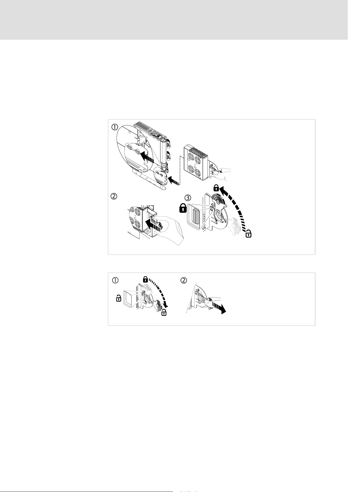
1.2.1.1 Mounting
Safety engineering
Device modules
Slot
The slot for the safety modules is marked in the documentation with M4. It
is the lowest slot in the controller (see overview).
1.2
1.2.1
1
1.2.1.2 Dismounting
1.2.1.3 Module exchange
Every module exchange is detected by the basic device and documented in
a logbook.
When the module is replaced by the same type no restrictions arise.
When the module isreplacedby a different type, the drive is inhibited bythe
controller. The inhibit can only be deactivated when the parameter setting
of the required safety module complies with the plugged safety module.
E94AYAX001
E94AYCXX001H
EDS94AYAD EN 2.2
1.2-1
Page 12
1
M
SMx
PWM
µC
PC
3x
3x
Xx
1.2
1.2.2
Safety engineering
Device modules
Function mode of the safety modules
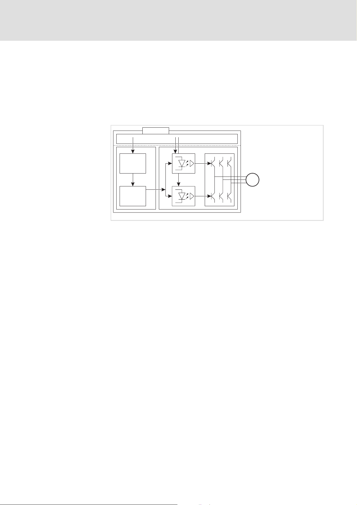
1.2.2 Function mode of the safety modules
C00214
Disconnecting paths
The code C00214 must comply with the plug-in safety module type so that
thecontrollerisabletooperate.
The transmission of the pulse width modulation is safely (dis-)connected by
thesafetymodule. Hencethe driversdonot createa rotating field.The motor
is safely switched to torqueless operation (STO).
SSP94SM320
Fig. 1.2-1 Disconnecting paths of the safety modules
SMx Safety module SM100/SM300
xx Input / output terminal
C Control section
μC Microcontroller
PWM Pulse width modulation
PPowersection
M Motor
Safety status
Fail-safe status
1.2-2
When the controlleri s switched off by a safety module,the”Safe torque off”
status is set (C00183 = 101).
If internal errors of the safety modules are detected, the motor is safely
switched to torque-free operation (fail-safe status).
EDS94AYAD EN 2.2
Page 13

1.2.3 Safety module SM300
1.2.3.1 Overview
ThetypedesignationofthesafetymoduleisE94AYAD.
Functions
ƒSafetorqueoff(STO)
(previously: safe standstill, protection against unexpected start-up)
ƒ Safe stop 1 (SS1)
ƒ Connection of safety sensors
ƒ PROFIsafe safety bus connection
The SM300 supports the transmission of safe information on the PROFIsafe
protocol according to the specification ”PROFIsafe - Profile for Safety
Technology”, Version 1.30, of the PROFIBUS Nutzerorganisation (PNO). The
basic device transmits the PROFIsafe information to the SM300 for safe
evaluation.
Safety engineering
Device modules
Safety module SM300
1
1.2
1.2.3
1.2.3.2 Safety category
The following applies to the SM300 safety module , version VA 1.xx:
ƒ The basic device must be equipped with a communication module
E94AYCPM (PROFIBUS-DP), SW version 0.9.
ƒ The safe parameter setting is not supported. For this reason, all
parameters are permanently set.
ƒ The stopping time of the SS1 cannot be parameterised. It is
permanently set to t
ƒ This module does not support (safe) outputs.
=30s.
s
Danger!
If the request for the safety function is cancelled, the drive will
restart automatically.
You must provide external measures which ensure that the drive
only restarts after a confirmation (EN 60204).
The implemented safety functions meet the requirements of the standards:
ƒ Control category 3 according to EN 954-1
In order to comply with category 3, the external wiring and cable
monitoring must also meet the requirements of category 3.
EDS94AYAD EN 2.2
1.2-3
Page 14

1
1.2
1.2.3
Safety engineering
Device modules
Safety module SM300
1.2.3.3 Elements of the module
Fig. 1.2-2 Module view
Pos. Description
X82.1
X82.2
X82.3
X82.4
SSP94SM317
PROFIsafe target address switch (on the left housing side)
Pluggable terminal strips for input and output signals
Displays
Pos. Colour State Description
On Drive-based safety is initialised faultlessly.
Drive-based safety is initialised faultlessly. Internal
MS Green
EN Yellow
ME Red
PS Red
DE Red On
Blinking
Off Drive-based safety is not initialised.
On Controller enabled
Off Non-safe display ”STO”
On
Blinking
Flashing
Off Error-free operation
On
Blinking No valid PROFIsafe configuration
Off PROFIsafe is error-free.
communication to the standard device is not
possible.
Acknowledgement is not possible.
System error:
z After a serious internal error, STO is activated.
z Can only be reset by switching the 24V supply.
Error:
z Afteraninternalerrororanerroratthesafe
inputs, a standstill function is activated.
z The safety class is quit.
z Acknowledgement is possible.
Fault:
z A monitoring function has responded and
activated a standstill function.
z The safety class is not quit.
z Acknowledgement is possible.
Error PROFIsafe:
z Communication is not possible.
z Acknowledgement is possible.
Themoduleisnotacceptedbythestandarddevice
(see notes given in the documentation for the
standard device).
1.2-4
EDS94AYAD EN 2.2
Page 15

Safety engineering
Device modules
Safety module SM300
1
1.2
1.2.3
Terminal assignment
X82.1 Labelling Description
n. c.
n. c.
n. c.
n. c.
n. c.
n. c.
n. c.
n. c.
n. c.
X82.2 Labelling Description
- GND external supply
+ 24 V external supply via a safely separated power supply unit
n. c.
n. c.
n. c.
n. c.
AIE Error confirmation input (Acknowledge Input Error)
CLA Clock output for passive sensors, channel A (clock A)
CLB Clock output for passive sensors, channel B (clock B)
This terminal strip is not assigned.
(SELV/PELV)
This part of the terminal strip is not assigned.
X82.3 Labelling Description
GCL GND clock output
GI2 GND IN I2A/I2B
I2B Sensor input 2, channel B (only for passive sensors)
I2A Sensor input 2, channel A (only for passive sensors)
GCL GND clock output
GI1 GND I1A/I1B
I1B Sensor input 1, channel B (only for passive sensors)
I1A Sensor input 1, channel A (only for passive sensors)
n. c. This terminal is not assigned.
X82.4 Labelling Description
GCL GND clock output
GI4 GND I4A/I4B
I4B Sensor input 4, channel B (only for active sensors)
I4A Sensor input 4, channel A (only for active sensors)
n. c.
n. c.
n. c.
n. c.
n. c.
This part of the terminal strip is not assigned.
Sensor input 3 is not available.
EDS94AYAD EN 2.2
1.2-5
Page 16

1
1.2
1.2.3
Safety engineering
Device modules
Safety module SM300
1.2.3.4 Technical data
Cable cross-sections and tightening torques
Type [mm2] [Nm] AWG [lb-in]
Wire end ferrule,
insulated
Rigid 0.14 ... 1.5 26 ... 16
0.25 ... 0.5
Spring terminal
24 ... 20
Spring terminal
24 V
The inputs are isolated and designed for a low-voltage supply of 24 V DC.
Detailed features of the inputs and outputs
Signal Specification min. typ. max.
I1A, I1B
I2A, I2B
I4A, I4B
AIE
AIE Pulse duration [ms] 300 10
CLA, CLB
+, -
Tab. 1.2-1 Technical data
PLC input, IEC-61131-2, 24 V, type 1
LOW signal [V] -3 0 5
Input current [mA] 15
HIGH signal [V] 15 24 30
Input current [mA] 2 15
Input capacitance [nF] 3.3
PLC output, IEC-61131-2, 24 V DC, 50 mA
LOW signal output voltage [V] 0 0.8
HIGH signal output voltage [V] 17 24 29
Output current [mA] 50
Width of the test pulse [μs] 750
Test pulse rate [s] 1.8
Cable resistance of a passive sensor [kΩ] 2
Supply voltage of the module via a safely
separated power supply unit (SELV/PELV)
Input current [A]
[V] 19,2 24 30
4
1.2.3.5 Commissioning
The chapter ”Response times” must be observed as well ( 1.3.5.2).
ƒ Settings in or at the module:
– PROFIsafe target address switch
ƒ Required settings in the basic device:
– C00214, type of safety module
ƒ Integration of the SM300 into the drive application
ƒ During commissioning and after the replacement of a module it is vital
to check the safety function.
1.2-6
EDS94AYAD EN 2.2
Page 17

1.2.3.6 Test certificate
Safety engineering
Device modules
Safety module SM300
1
1.2
1.2.3
SSP94TUEV3
Fig. 1.2-3 TÜV Certificate
The type test was carried out by ’TÜV Rheinland Group’ and confirmed with
a certificate.
Contents Specifications
Test institute TÜV Industrie Service GmbH, ASI area
Test report 968/EL 302.01/05
Test fundamentals EN 954-1, EN 60204-1, EN 50178, EN 61800-3, IEC 61508 Part 1-7
Object to be examined SM300, type E94AYAD VA1.xx of the 9400 Servo Drives range
Test result The module meets the requirements according to EN 954-1,
Special conditions The safety instructions in the corresponding user documentation
Place of issue Cologne
Issue date 30.06.2005
category 3.
must be observed.
EDS94AYAD EN 2.2
1.2-7
Page 18

1
1.2
1.2.4
1.2.4 Connection of safety sensors
1.2.4.1 General
Safety engineering
Device modules
Connection of safety sensors
The following applies to the sensors of the SM300, version VA 1.xx:
ƒ Sensor type and function cannot be parameterised.
ƒ The sensor signals are converted into PROFIsafe bit information and
transmitted to the master control for processing. A local evaluation is
not carried out.
ƒ Unused sensor inputs must not be connected. The PROFIsafe bit of a
non-connected input is in the OFF state.
Note!
Make sure that an internal contact function test is carried out at
thesafeinputs:
Safe input in the ON state
ƒ ALOWlevelatone channel puts the input in the OFF state.
The discrepancy monitoring starts simultaneously.
ƒ A LOW level must be detected at both channels within the
discrepancy time, otherwise a discrepancy error will be
reported.
ƒ To be able to confirm the discrepancy error, a LOW level must
be detected before at both channels.
Safe input in the OFF state
ƒ A HIGH level at one channel starts the discrepancy monitoring.
ƒ A HIGH level must be detected at both channels within the
discrepancy time, otherwise a discrepancy error will be
reported.
ƒ To be able to confirm the discrepancy error, a HIGH level must
be detected before at both channels.
1.2-8
EDS94AYAD EN 2.2
Page 19

Safety engineering
Device modules
Connection of safety sensors
1
1.2
1.2.4
Specification
passive active
Discrepancy time 30 s
Input delay 4ms 0ms
Input filter time for test pulses 15 ms
Repetition rate of the test
pulses
Error response EC_S1
Tab. 1.2-2 Specification of sensor connections
is determined by the clock
outputs CLA and CLB
Confirmation via PROFIsafe or AIE input
Sensor type
>50ms
Explanations
Discrepancy time
ƒ Maximum time in which both channels of a safe input may have
non-equivalent states without the safety engineering noticing an error.
Input delay
ƒ Time between the recognition of the signal change and the effective
evaluation of an input signal. As a result, multiple and short signal
changes due to contact bounce of the components are not taken into
account.
Input filter time
ƒ Time in which the interference pulses and test pulses are not detected
by e.g. active sensors that are switched on.
EDS94AYAD EN 2.2
1.2-9
Page 20

1
1.2
1.2.4
Safety engineering
Device modules
Connection of safety sensors
1.2.4.2 Connection of passive sensors
The safe sensor inputs I1A, I1B and I2A, I2B are only s uitable for equivalent
switching passive sensors.
To monitor passive sensors according to EN 954-1, cat. 3, the clock outputs
CLA and CLB must be wired. Please observe the following:
ƒ The clock outputs are only suitable for monitoring the passive sensors.
ƒ Always connect ...
– ... CLA with the A channel of the sensor input via the sensor.
– ... CLB with the B channel of the sensor input via the sensor.
–...GCLwithGIxofthesensorinput.
ƒ The sensor inputs are tested cyclically through short LOW operation.
These errors are detected:
ƒ Short circuit to supply voltage.
ƒ Short circuit between the input signals when different clock outputs
are used.
ƒ Non-equivalent input signals after the discrepancy time.
These errors are not detected:
ƒ Short circuit between the input signals when the same clock outputs
are used.
Avoid unrecognisable errors by the installation, e.g. by separated cable
routing.
V
CC
CLA
CLB
GCL
GI2
I2B
S2
û
I2A
GCL
SM300
E94AYAD
1.2-10
û
S1
Fig. 1.2-4 Ways to detect errors
8 Unrecognisable errors
GI1
I1B
I1A
SSP94SM351
EDS94AYAD EN 2.2
Page 21

1.2.4.3 Connection of active sensors
The safe sensor input I4A and I4B is suitable for an active sensor.
PN-switched input signals are permissible.
The line monitoring must comply with the requirements of the category 3 .
Drive-based safety does not provide for line monitoring.
These errors are detected:
ƒ Non-equivalent input signals after the discrepancy time.
Safety engineering
Device modules
Connection of safety sensors
1
1.2
1.2.4
IA
IB
GI
Fig. 1.2-5 Functional example of PN-switching sensor
P
M
S
SSensor
P Positive path
M Negative path
SSP94SM352
EDS94AYAD EN 2.2
1.2-11
Page 22

1
1.2
1.2.4
Safety engineering
Device modules
Connection of safety sensors
1.2.4.4 Connection plans
SM300
E94AYAD
X82.1 X82.2
-
+
AIE
CLA
CLB
24 V ext.
GCL
GI2
I2B
I2A
S2
S1
GCL
GI1
I1B
I1A
X82.3
GCL
GI4
I4B
I4A
Fig. 1.2-6 Wiring example SM300
E94AYAD Safety module SM300, version VA1.xx
S1
S2
passive sensor with channel A and B
S4 Lightgrid (active sensor)
24Vext. 24-Vvoltagesupply(SELV/PELV)
S4
X82.4
SSP94SM350
1.2-12
EDS94AYAD EN 2.2
Page 23

Integration into the application of the controller
1.3 Safety functions
1.3.1 Integration into the application of the controller
For the use of the functions, certain settings in the controller are required.
Here, the Lenze PC software »Engineer« supports and guides you.
When a safety function is required, the safety technology activates the
corresponding safe monitoring function. However, the standstill function is
only directlyexecuted with the”safe torque off”(STO)function. Othersafety
functions in which a controller action is required will need to be safely
monitored.
The actions of the drive (e.g. braking, braking to standstill, keeping the
standstill position) must be implemented in the basic device.
Depending on the design of the basic device, the user applications are
created by means of programming according to IEC 61131 or parameter
setting. For this purpose the system block InterfaceSafetyModule or the
control word SM_dwControl must be implemented into the control
configuration of the controller.
Safety engineering
Safety functions
1
1.3
1.3.1
Internal communication
The connection to a user application serves to achieve the following:
1. Activation of the safety function in the safety module, e.g. SS1 the
monitoring starts.
2. The safety module transmits the information to the basic device that
the function has been activated using the corresponding bit in the
control word SM_dwControl.
3. The application must evaluate the control word and start the motion
sequence, e.g. braking etc.
Safety module and basic device communicate via an internal interface.
The request for a safety function is contained within the control word, the
information of which must be processed by the application.
Informatio
n
SM_
dwControl
SM_
wState
SM_wIo_
State
Tab. 1.3-1 Communication telegram from the safety module to the basic device.
Offset Bit
Byte 7 6 5 4 3 2 1 0
4SDIp
5 - - - - - - - SDIn
6 - - - - - - - 7 - - - - - - - 8 - - - EC_S1 EC_S0 - - STO
9 - - - - - - - 10 - AIE - - SD-In4 - SD-In2 SD-In1
11 - - - - - - - -
- - - - - SS1 STO
EDS94AYAD EN 2.2
1.3-1
Page 24

1
1.3
1.3.1
Safety engineering
Safety functions
Integration into the application of the controller
Details SM_dwControl
Name Value Description IEC 61800-5-2
STO
SS1
SDIp 1 Safe positive direction of rotation enabled (fixed) Safe Direction
SDIn 1 Safe negative direction of rotation enabled (fixed) Safe Direction
- 0 Reserved for future extensions
Details SM_wState
Name Description IEC 61800-5-2
EC_S1
EC_S0
STO
0
No request
1 Request of the function
0 No request
1 Request of the function
0
Normal operation
1 Stop category 1 error activated
0 Normal operation
1 Stop category 0 error activated
0 Normal operation
1 Pulse inhibit activated
Safe Torque Off
Safe Stop 1
-
-
Safe Torque Off
Details SM_wIo_State
Name Value Description
SD-I1
SD-I2
SD-I4
AIE
0
Sensor input 1 in the OFF state, at least one channel
1 Sensor input 1 in the ON state
0 Sensor input 2 in the OFF state, at least one channel
1 Sensor input 2 in the ON state
0 Sensor input 4 in the OFF state, at least one channel
1 Sensor input 4 in the ON state
0 Idle state
0 1 Error confirmed
1 Temporary status
If the communication with the basic device is interrupted, e.g. by switching
off thebasic device, afault is activatedand the LED”ME” begins blinking.The
required confirmation can be executed via AIE or PROFIsafe. Further
information can be obtained from the chapter ”Error status”.
1.3-2
EDS94AYAD EN 2.2
Page 25

1.3.2 Error states
Safety engineering
Safety functions
Error states
Detectederrorsor maloperationofthe driveareassigned toerrorstates with
definite reactions. The reaction can beco-ordinatedwiththe complete drive
via the error states.
1.3
1.3.2
1
Features
System error Error Trouble
Event Fatal internal error Error Monitoring function
LED ”ME” On Blinking Flashing
Status of safety
module
The control category
according to EN 954-1
...
Reaction The motor
Confirmation after
deactivated event
Response to the
confirmation
Tab. 1.3-2 Overview of error states
Lockout (CPU stopped) Error status Normal operation
... has been
abandoned
immediately switches
to torque-free
operation via
z STO
z Connection and
disconnection of
the 24-V supply at
the safety module
z Themoduleisreset.
z The PROFIsafe communication is
interrupted.
Error status
... has been
abandoned
The motor is stopped via
z STO or
z SS1
z Pulse at AIE
(0.3 s < t < 10 s)
z via PROFIsafe
z Connection and
disconnection of
the 24-V supply at
the safety module
... has not been
abandoned
z Pulse at AIE
(0.3 s < t < 10 s)
z via PROFIsafe
z Themoduleisnot
reset.
z The PROFIsafe
communication is
not interrupted.
If errors occur inthePROFIsafe communication, the data is deactivated from
the PROFIsafe driver. The STO function is activated.
After the PROFIsafe communication is reinitialised, the drive is
automatically enabled again if no standstill function is selected.
Note!
If the system error also occurs after switching the 24-V supply,
please contact the service.
EDS94AYAD EN 2.2
1.3-3
Page 26

1
1.3
1.3.2
Safety engineering
Safety functions
Error states
Logbook
Entries
Error states are saved in the logbook of the standard device. The following is
entered:
ƒ Decimal error number without plain text
ƒ A time mark for each event
The available logbook entries can be displayed in the »Engineer« when an
online connection has been established.
Events which cause an error status are sent as a diagnostic telegram via
PROFIBUS.
Area Description Error status, note
Error
number
Stop functions
0
0x00 Not used 1 0x01 Internal error, STO error is active STO error
2 0x02 Internal error, SS1 error is active SS1 error
PROFIsafe
33 0x21 Invalid PROFIsafe target address STO error
34 0x22 PROFIsafe communication error
35 0x23 PROFIsafe monitoring time activated
36 0x24 PROFIsafe deactivated
37 0x25 PROFIsafe has left DataExchange
38 0x26 Invalid data in the PROFIsafe user area
39 0x27 Wrong parameters received from F-PLC
Inputs
49 0x31 Discrepancy error - input SD-In1
50 0x32 Discrepancy error - input SD-In2
52 0x34 Discrepancy error - input SD-In4
54 0x36 Discrepancy error - input AIE STO error
Test functions
81 0x51 Internal short circuit in one of the inputs
82 0x52 Short circuit in one of the clock outputs CLA or CLB
93 0x5D Internal error of the safe switch-off logic STO error
Safety functions
97 0x61 SS1: The drive has not reached zero speed within the
stopping time (30 s).
Tab. 1.3-3 Description for the numerical entries
STO, no error status
no diagnostic
telegram via
PROFIBUS
SS1 error
SS1 error
STO error
1.3-4
EDS94AYAD EN 2.2
Page 27

1.3.3 Safe torque off
1.3.3.1 Description
Safety engineering
Safety functions
Safe torque off
Safe Torque Off / STO
This function corresponds to a ”Stop 0” according to EN 60204.
When this function is used, the power supply of the motor is immediately
safely interrupted. The motorcannotcreatea torque and thus no dangerous
movements of the drive can occur. Additional measures, e.g. mechanical
brakes are needed against movements caused by external force.
Priority function: none
Subordinated function: SS1
'1'
1.3
1.3.3
0
1
1.3.3.2 Conditions
0
n
t
1
0
Condition for using the function:
ƒ The basic device must be equipped with a communication module
E94AYCPM (PROFIBUS-DP), SW version 0.9 and connected to the
PROFIBUS.
ƒ The basic device must receive PROFIBUS data telegrams from a master
controller.
t1
Input signal of the request of a safety function
’1’ Logic signal level ”1” / ”true”
Speed characteristic n of the motor
tx Action instant
tTimeaxis
t
SMxDIASTO
1.3.3.3 Settings
EDS94AYAD EN 2.2
Danger!
If the request for the safety function is cancelled, the drive will
restart automatically.
You must provide external measures which ensure that the drive
only restarts after a confirmation (EN 60204).
This function does not have any parameters to be set.
1.3-5
Page 28

1
1.3
1.3.3
1.3.3.4 Activation
Safety engineering
Safety functions
Safe torque off
How to activate the function:
ƒ A PROFIBUS data telegram with corresponding PROFIsafe contents is
transmitted to the basic device ( 1.3-12).
1.3-6
EDS94AYAD EN 2.2
Page 29

1.3.4 Safe stop 1
1.3.4.1 Description
Safety engineering
Safety functions
Safe stop 1
Safe Stop 1 / SS1
This function corresponds to a ”Stop 1” according to EN 60204.
When this function is used, the motor is stopped within an adjustable
stopping time. The complete function sequence cannot be deactivated.
When the speed n = 0 is reached or the stopping time elapses, the power
supply of the motor is immediately safely interrupted (STO), depending on
which event occurs first. The motor cannot create torque and thus no
dangerous movements of the drive can occur. Additional measures, e.g.
mechanical brakesareneeded against movements caused byexternalforce.
Priority function: STO
Subordinated function: None
'1'
1.3
1.3.4
1
0
1
0
t
S
n
0
t1 t2
Input signal of the request of a safety function
’1’ Logic signal level ”1” / ”true”
Speed characteristic n of the motor
tx Action instant
t
Monitored stopping time
S
–– Normal operation
--- Incorrect operation
tTimeaxis
t
t
SMxDIASS1
EDS94AYAD EN 2.2
1.3-7
Page 30

1
1.3
1.3.4
1.3.4.2 Conditions
1.3.4.3 Settings
Safety engineering
Safety functions
Safe stop 1
Condition for using the function:
ƒ The basic device must be equipped with a communication module
E94AYCPM (PROFIBUS-DP), SW version 0.9 and connected to the
PROFIBUS.
ƒ The basic device must receive PROFIBUS data telegrams from a master
controller.
Danger!
If the request for the safety function is cancelled, the drive will
restart automatically.
You must provide external measures which ensure that the drive
only restarts after a confirmation (EN 60204).
This function does not have any parameters to be set.
1.3.4.4 Activation
Permanently set parameters:
ƒ The stopping time amounts to t
=30s.
s
Tip!
In many applications the stopping time is < 30 s. Thus STO is
already activated and the SS1 function is stopped when ”0”
speed is reached.
Inordertodeterminethemaximumresponsetimeconsiderthe
stopping time (30 s).
This time can only be reduced by setting the STO function
through the safe control after the application-specific stopping
time.
How to activate the function:
ƒ A PROFIBUS data telegram with corresponding PROFIsafe contents is
transmitted to the basic device ( 1.3-12).
1.3-8
EDS94AYAD EN 2.2
Page 31

1.3.5 Safe PROFIsafe connection
1.3.5.1 Conditions
The SM300 supports the transmission of safe information on the PROFIsafe
protocol according to the specification ”PROFIsafe - Profile for Safety
Technology”, Version 1.30, of the PROFIBUS Nutzerorganisation (PNO). The
basic device transmits the PROFIsafe information to the SM300 for safe
evaluation.
Condition for using the function:
ƒ The basic device must be equipped with a communication module
E94AYCPM (PROFIBUS-DP), SW version 0.9 and connected to the
PROFIBUS.
ƒ The basic device must receive PROFIBUS data telegrams from a master
controller.
Safety engineering
Safety functions
Safe PROFIsafe connection
1
1.3
1.3.5
EDS94AYAD EN 2.2
1.3-9
Page 32

1
1.3
1.3.5
Safety engineering
Safety functions
Safe PROFIsafe connection
1.3.5.2 Response times
In order to detect the response time to a safety function the entire system
must be considered. The following is relevant:
ƒ Response time of the connected sensors.
ƒ Input delay of the safety inputs.
ƒ Internal processing time.
ƒ Monitoring time for the cyclic service in the PROFIBUS.
ƒ Monitoring time of the PROFIsafe in the safety PLC.
ƒ Processing time in the safety PLC.
ƒ Delay times due to further components.
0
1
t=0
S
t
1
t
2
μC
t
3
t
ps
PROFIBUS
t
5
SF
2
t
4
μC
Fig. 1.3-1 Response times to the request of a safety function
Basic device
Safety module
Safety PLC
μC Microcontroller
S Safety sensor technology
SF Activated safety function
lcu12x_352
1.3-10
EDS94AYAD EN 2.2
Page 33

Safety engineering
Safety functions
Safe PROFIsafe connection
Response time to an event in the safety sensors (PROFIsafe input data)
Time interval (Fig. 1.3-1) [ms]
t1Response time of the sensors according to manufacturer
t
Input delay of the safe inputs
2
passive sensors: 4+15
active sensors: 0+15
t3Processing time in drive-based safety 24
PROFIsafe input data ready for transmission to ... Σ
tPsPROFIsafe cycle time according to manufacturer
PROFIsafe input data ready for processing in the safety PLC
...
Tab.1.3-4 Responsetimetoaneventinthesensors
Response time to a PROFIsafe control word (PROFIsafe output data)
Time interval (Fig. 1.3-1) [ms]
t4Processing time in the safety PLC must be calculated
tPsPROFIsafe cycle time according to manufacturer
t5Processing time in drive-based safety 14
Safety function starts after ... Σ
Tab.1.3-5 ResponsetimeincaseofPROFIsaferequest
information
information
Σ
information
Information on how to calculate the processing time and transmission time
of the PROFIsafe can be found in the documentation of the safety PLC used.
1.3
1.3.5
1
Example
Note!
When the PROFIsafe communication is disturbed, it is changed
to the fail-safe state after the PROFIsafe monitoring time
(F_WD_Time) has elapsed. ( Tab. 1.3-16)
ƒ After an event has occurred at a safe input, the message is fed back to
drive-based safety via the safety PLC.
ƒ Drive-based safety activates a safety function.
ƒ Hence, the maximum response time to the event is calculated as
follows:
t
max response=t1+t2+t3
When calculating the maximum response time, include the times of the
safety functions, e.g. in case of SS1 the stopping time (30 s) until STO is
active.
+max{tWD;tPS+t4+tPs+t5}
EDS94AYAD EN 2.2
1.3-11
Page 34

1
1.3
1.3.5
1.3.5.3 Description
Safety engineering
Safety functions
Safe PROFIsafe connection
Addressing
PROFIsafe frame
An unambiguous PROFIsafe target address ensures that a data telegram
reaches the correct node.
The validaddress within the rangebetween 1 and 1023can be set viathe DIP
switch . The address 0 is invalid and causes an error in the module.
DIP switch Labelling
1 2 3 4 5 6 7 8 9 0
Value of the address bit 1 2 4 8 16 32 64 128 256 512
Tab. 1.3-6 Address setting
Note!
The combination ”safety module SM300 from version VA 1.08
and communication module PROFIBUS from version VB 0.93”
offers the opportunity to avoid the error that occurs when an
address is set to 0. For this purpose, a defined PROFIsafe target
address must be saved in C13897 or 14897 in the PROFIBUS
communication module.
The PROFIsafe data is transmitted in the first slot of a PROFIBUS data
telegram.
This must be observed for the hardware configuration of the safety PLC!
PROFIBUS data telegram
Header PROFIsafe data Data Trailer
Slot 1 Slot 2
1.3-12
EDS94AYAD EN 2.2
Page 35

Safety engineering
Safety functions
Safe PROFIsafe connection
1
1.3
1.3.5
PROFIsafe data
In thePROFIsafe data onebiteach is usedto control acertainsafety function.
The structure of the PROFIsafe dataisdescribed in the PROFIsafe profile. The
length of the PROFIsafe data (PROFIsafe message) in slot 1 permanently
amounts to 8 bytes in the SM300. They are composed according to the
following structure:
Offset Bit
Byte 7 6 5 4 3 2 1 0
0
1
2
3
4 Control byte or status byte
5 Consecutive number
6
7
Tab. 1.3-7 Structure of the PROFIsafe data
(Signature consists of PROFIsafe process data and PROFIsafe parameters)
PROFIsafe process data
(safe user data)
CRC2
The meaning of the PROFIsafe process data is separately described for
PROFIsafe output data and PROFIsafe input data. All described bits are
evaluated.
Unassignedbitsare reserved forfuture functions andmarked with ”-”.These
bits must transmitted with ”0”.
PROFIsafe output data
The PROFIsafe output data is transmitted from the control to the safety
module.
Offset Bit
Byte 7 6 5 4 3 2 1 0
0-- - - - - SS1 STO
1 - - - - - - - 2 - - - - - - PS_AIE 3 - - - - - - - -
Tab. 1.3-8 Structure of the PROFIsafe output data
Details of the PROFIsafe output data
Name Value Description
STO
SS1
PS_AIE
- 0 Reserved for future extensions
Tab. 1.3-9 Detailed specification of the PROFIsafe output data
0
The STO function is activated.
1 The function is deactivated.
0 The SS1 function is activated. The complete function sequence cannot be
deactivated.
1 The function is deactivated.
0 Idle state
0 1 Activation of fault acknowledgement
The bit must be set for at least one PROFIsafe cycle.
EDS94AYAD EN 2.2
1.3-13
Page 36

1
1.3
1.3.5
Safety engineering
Safety functions
Safe PROFIsafe connection
Control byte
PROFIsafe input data
Only the bits specified of the PROFIsafe control byte are supported:
Offset Bit
Byte 7 6 5 4 3 2 1 0
4 - - - activate
_FV
Tab. 1.3-10 Structure of the PROFIsafe control byte
Details of the control byte
Name Value Description
activate_FV
- 0 Reserved for future extensions
Tab. 1.3-11 Detail specification of the control byte
1
The PROFIsafe output data is deactivated. Thus, the STO function is
activated.
0 The function is deactivated.
- - - -
The PROFIsafe input data is transmitted to the control by the safety module.
Offset Bit
Byte 7 6 5 4 3 2 1 0
0-- - - - - Status
SS1
1 - - - - - - - 2 - - - - - - - 3 Error - - - SD-In4 - SD-In2 SD-In1
Tab. 1.3-12 Structure of the PROFIsafe input data
Status
STO
Details of the PROFIsafe input data
Name Value Description
STO
SS1
SD-In1
SD-In2
SD-In4
Error
- 0 Reserved for future extensions
Tab. 1.3-13 Detailed specification of the PROFIsafe input data
0
The STO function is not active.
1 The STO function is active and the drive is safely switched to torque-free
operation.
This bit is also set at the end of the stopping time by SS1.
0 The SS1 function is not active.
1 The SS1 function is active.
At the end of the function the STO bit is set.
0
Sensor at I1A and I1B
1 The channels A and B are in the ON state
0
Sensor at I2A and I2B
1 The channels A and B are in the ON state
0
Sensor at I4A and I4B
1 The channels A and B are in the ON state
0 Error status is not active.
1 Error status is active.
At least one channel is in the OFF state
At least one channel is in the OFF state
At least one channel is in the OFF state
1.3-14
EDS94AYAD EN 2.2
Page 37

Safety engineering
Safety functions
Safe PROFIsafe connection
1
1.3
1.3.5
Status byte
PROFIsafe parameters
Only the bits specified of the PROFIsafe status byte are supported:
Offset Bit
Byte 7 6 5 4 3 2 1 0
4 - - - FV_activatedCOM-Failure
Tab. 1.3-14 Structure of the PROFIsafe status byte
Details of the status byte
Name Value Description
COM-Failur
eCRC
COM-Failur
e
WD-Timeo
ut
FV_activate
d
- 0 Reserved for future extensions
Tab. 1.3-15 Detail specification of the status byte
Status is not active.
0
1 Status after communication error is active.
0 Status is not active.
1 Status after time-out is active.
0 The function is not active.
1 The PROFIsafe input data is deactivated.
WD-Timeout
COM-Failure
CRC
- -
These PROFIsafe parameters and contents are supported:
PROFIsafe parameters
Name Description Valid contents
F_Source_Add PROFIsafe source address of the safety PLC 0x01 ... 0xFFFE
F_Dest_Add PROFIsafe target address of the safety module 0x01 ... 0x3FF
F_WD_Time PROFIsafe monitoring time of the safety module 110 ... 65535 ms
F_Check_SeqNo Check sequence no. in CRC 0
F_Check_iPar Check iparameters CRC3 in CRC 0
F_SIL Supported SIL (Safety Integrity Level) 0 Æ SIL1
Æ SIL2
1
2
Æ SIL3
F_CRC_Length Length of CRC 1
F_Block_ID Identification of the parameter type 0
F_Par_Version Version of the safety layer 0
F_Par_CRC Cyclic CRC Is calculated
Tab. 1.3-16 Supported PROFIsafe parameters
Diagnostic messages
EDS94AYAD EN 2.2
Incorrect configurations of the PROFIsafe parameters are reported to the
safety PLC by means of a diagnostic telegram ( PROFIBUS Communication
Manual).
1.3-15
Page 38

1
1.3
1.3.5
Safety engineering
Safety functions
Safe PROFIsafe connection
Diagnostic information
GSE file
Error number Description
64 The Profisafe target address set does not comply with the parameter
F_Dest_Add.
65 The F_Dest_Add parameter has the invalid value 0x0000 or 0xFFFF.
66 The F_Source_Add parameter has the invalid value 0x0000 or 0xFFFF.
67 The F_WD_Time parameter has the invalid value 0 ms.
68 TheF_SILparameterdoesnothavethevalidvalue0...2.
69 The F_CRC_Length parameter does not have the valid value 2.
70 The version of the PROFIsafe parameter set is wrong.
71 CRC1 error
Tab. 1.3-17 Information contents of byte 11
The GSE file contains all information on the configuration of the PROFIBUS
system. This makes the integration easy and user-friendly.
Tip!
You will find the current GSE file for this Lenze product in the
Internet in the ”Downloads” area under
http://www.Lenze.com
1.3-16
EDS94AYAD EN 2.2
Page 39

1.4 Acceptance
1.4.1 Description
Safety engineering
Acceptance
Description
The machine manufacturer must check and prove the operability of the
safety functions used.
1.4
1.4.1
1
Inspector
Protocol
Scope
The machine manufacturer must authorise a person with expertise and
knowledge of the safety functions to carry out the test.
The test result of every safety function must be documented and signed.
A complete test comprises the following:
ƒ Documentation of the plant including the safety functions.
– Plant description and overview map
– Description of the safety devices
– Safety functions used
ƒ Functional test of all safety functions used.
ƒ Preparing the test report
– Documenting the functional test
– Controlling the parameters
– Signing
ƒ Preparing the appendix with test records
– Protocols from the plant
– External recording
1.4.2 Periodic inspections
The correct sequence of the safety-oriented functions must be checked in
periodic inspections. The risk analysis or applicable regulations determine
the time distances between the tests. The inspection interval should not
exceed one year.
EDS94AYAD EN 2.2
1.4-1
Page 40

Lenze Drive Systems GmbH
Hans-Lenze-Straße 1
D-31855 Aerzen
Germany
Service
¬ Service
E-Mail Lenze@Lenze.de
Internet www.Lenze.com
+49 (0) 51 54 82-0
00 80 00 24 4 68 77 (24 h helpline)
+49 (0) 51 54 82-1112
EDS94AYAD 2.2 10/2006
© 2006
TD14
10987654321
 Loading...