

Page 1
EDK82ZAFSC
.=#y
Montageanleitung
Mounting Instructions
Instructions de montage
STANDARD−I/O
Ä.=#yä
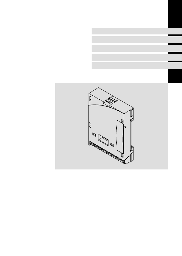
E82ZAFSC / E82ZAFSC001
Funktionsmodul
Function module
Module de fonction
Page 2

Lesen Sie zuerst diese Anleitung und die Dokumentation zum Grundgerät,
bevor Sie mit den Arbeiten beginnen!
Beachten Sie die enthaltenen Sicherheitshinweise.
Please read these instructions and the documentation of the standard
device before you start working!
Observe the safety instructions given therein!
Lire le présent fascicule et la documentation relative à l’appareil de base
avant toute manipulation de l’équipement !
Respecter les consignes de sécurité fournies.
Page 3
E82ZAFS002A
Page 4

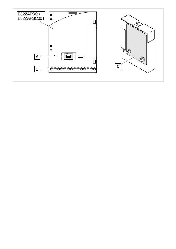
Legende zur Abbildung auf der Ausklappseite
Pos. Beschreibung Ausführliche
Funktionsmodul E82ZAFSC / E82ZAFSC001
Schalter zur Konfigurierung des Analogeingangs (Klemme X3/8) 21
Digitale und analoge Ein− und Ausgänge, Klemmenleiste X3 19
Typenschild 12
0Abb. 0Tab. 0
Information
4
EDK82ZAFSC DE/EN/FR 5.0
Page 5

Inhalt i
1 Über diese Dokumentation 6 . . . . . . . . . . . . . . . . . . . . . . . . . . . . . . . . . . . . . . . . . .
Verwendete Konventionen 7 . . . . . . . . . . . . . . . . . . . . . . . . . . . . . . . . . . . . . . . . . .
Verwendete Hinweise 8 . . . . . . . . . . . . . . . . . . . . . . . . . . . . . . . . . . . . . . . . . . . . . . .
2 Sicherheitshinweise 9 . . . . . . . . . . . . . . . . . . . . . . . . . . . . . . . . . . . . . . . . . . . . . . . .
3 Produktbeschreibung 10 . . . . . . . . . . . . . . . . . . . . . . . . . . . . . . . . . . . . . . . . . . . . . . .
Funktion 10 . . . . . . . . . . . . . . . . . . . . . . . . . . . . . . . . . . . . . . . . . . . . . . . . . . . . . . . . . .
Bestimmungsgemäße Verwendung 10 . . . . . . . . . . . . . . . . . . . . . . . . . . . . . . . . . . .
Lieferumfang 11 . . . . . . . . . . . . . . . . . . . . . . . . . . . . . . . . . . . . . . . . . . . . . . . . . . . . . .
Identifikation 12 . . . . . . . . . . . . . . . . . . . . . . . . . . . . . . . . . . . . . . . . . . . . . . . . . . . . . .
4 Technische Daten 13 . . . . . . . . . . . . . . . . . . . . . . . . . . . . . . . . . . . . . . . . . . . . . . . . . .
Anschlussdaten 13 . . . . . . . . . . . . . . . . . . . . . . . . . . . . . . . . . . . . . . . . . . . . . . . . . . . .
Einsatzbedingungen 13 . . . . . . . . . . . . . . . . . . . . . . . . . . . . . . . . . . . . . . . . . . . . . . . .
Abmessungen 14 . . . . . . . . . . . . . . . . . . . . . . . . . . . . . . . . . . . . . . . . . . . . . . . . . . . . .
5 Mechanische Installation 15 . . . . . . . . . . . . . . . . . . . . . . . . . . . . . . . . . . . . . . . . . . . .
6 Elektrische Installation 16 . . . . . . . . . . . . . . . . . . . . . . . . . . . . . . . . . . . . . . . . . . . . . .
EMV−gerechte Verdrahtung 16 . . . . . . . . . . . . . . . . . . . . . . . . . . . . . . . . . . . . . . . . . .
Verdrahtung 17 . . . . . . . . . . . . . . . . . . . . . . . . . . . . . . . . . . . . . . . . . . . . . . . . . . . . . .
7 Inbetriebnahme 20 . . . . . . . . . . . . . . . . . . . . . . . . . . . . . . . . . . . . . . . . . . . . . . . . . . .
Vor dem ersten Einschalten 20 . . . . . . . . . . . . . . . . . . . . . . . . . . . . . . . . . . . . . . . . . .
DIP−Schalterstellung 21 . . . . . . . . . . . . . . . . . . . . . . . . . . . . . . . . . . . . . . . . . . . . . . . .
Inbetriebnahmeschritte 22 . . . . . . . . . . . . . . . . . . . . . . . . . . . . . . . . . . . . . . . . . . . . .
EDK82ZAFSC DE/EN/FR 5.0
5
Page 6

1 Über diese Dokumentation
1 Über diese Dokumentation
Inhalt
Diese Dokumentation enthält ...
ƒ Informationen zur mechanischen und elektrischen Installation des Funktionsmoduls;
ƒ Informationen zur Inbetriebnahme des Funktionsmoduls;
ƒ Sicherheitshinweise, die Sie unbedingt beachten müssen;
ƒ Angaben über Versionsstände der zu verwendenden Lenze Grundgeräte;
ƒ Technische Daten.
Informationen zur Gültigkeit
Die Informationen in dieser Dokumentation sind gültig für folgende Geräte:
Funktionsmodul Typenbezeichnung ab Hardwarestand
STANDARD−I/O E82ZAFSC 3A
STANDARD−I/O (verlackt) E82ZAFSC001 3A
Zielgruppe
Diese Dokumentation wendet sich an Personen, die das beschriebene Produkt nach Projektvorgabe installieren und in Betrieb nehmen.
Tipp!
Dokumentationen und Software−Updates zu weiteren Lenze Produkten finden
Sie im Internet im Bereich "Services & Downloads" unter
http://www.Lenze.com
6
EDK82ZAFSC DE/EN/FR 5.0
Page 7

Über diese Dokumentation
Verwendete Konventionen
Verwendete Konventionen
Diese Dokumentation verwendet folgende Konventionen zur Unterscheidung verschiedener Arten von Information:
Informationsart Auszeichnung Beispiele/Hinweise
Zahlenschreibweise
Dezimaltrennzeichen Punkt Es wird generell der Dezimalpunkt
Symbole
Seitenverweis
verwendet.
Beispiel: 1234.56
Verweis auf eine andere Seite mit zusätzlichen Informationen
Beispiel: 16 = siehe Seite 16
1
EDK82ZAFSC DE/EN/FR 5.0
7
Page 8

1 Über diese Dokumentation
Verwendete Hinweise
Verwendete Hinweise
Um auf Gefahren und wichtige Informationen hinzuweisen, werden in dieser Dokumentation folgende Piktogramme und Signalwörter verwendet:
Sicherheitshinweise
Aufbau der Sicherheitshinweise:
Gefahr!
(kennzeichnet die Art und die Schwere der Gefahr)
Hinweistext
(beschreibt die Gefahr und gibt Hinweise, wie sie vermieden werden kann)
Piktogramm und Signalwort Bedeutung
Gefahr von Personenschäden durch gefährliche elektrische
Spannung
Gefahr!
Gefahr!
Stop!
Anwendungshinweise
Piktogramm und Signalwort Bedeutung
Hinweis auf eine unmittelbar drohende Gefahr, die den Tod
oder schwere Verletzungen zur Folge haben kann, wenn
nicht die entsprechenden Maßnahmen getroffen werden.
Gefahr von Personenschäden durch eine allgemeine Gefahrenquelle
Hinweis auf eine unmittelbar drohende Gefahr, die den Tod
oder schwere Verletzungen zur Folge haben kann, wenn
nicht die entsprechenden Maßnahmen getroffen werden.
Gefahr von Sachschäden
Hinweis auf eine mögliche Gefahr, die Sachschäden zur
Folge haben kann, wenn nicht die entsprechenden Maßnahmen getroffen werden.
Hinweis!
Tipp!
8
Wichtiger Hinweis für die störungsfreie Funktion
Nützlicher Tipp für die einfache Handhabung
Verweis auf andere Dokumentation
EDK82ZAFSC DE/EN/FR 5.0
Page 9

Sicherheitshinweise 2
2 Sicherheitshinweise
Gefahr!
Unsachgemäßer Umgang mit dem Funktionsmodul und dem Grundgerät kann
schwere Personenschäden und Sachschäden verursachen.
Beachten Sie die in der Dokumentation zum Grundgerät enthaltenen
Sicherheitshinweise und Restgefahren.
Stop!
Elektrostatische Entladung
Durch elektrostatische Entladung können elektronische Bauteile innerhalb des
Funkionsmoduls beschädigt oder zerstört werden.
Mögliche Folgen:
ƒ Das Funktionsmodul ist defekt.
Schutzmaßnahmen
ƒ Befreien Sie sich vor dem Berühren des Moduls von elektrostatischen
Aufladungen.
EDK82ZAFSC DE/EN/FR 5.0
9
Page 10

3 Produktbeschreibung
Funktion
3 Produktbeschreibung
Funktion
Das Funktionsmodul ermöglicht das Ansteuern von Lenze Frequenzumrichtern und der
Lenze Antriebs−SPS mit analogen und digitalen Steuersignalen.
Bestimmungsgemäße Verwendung
Das Funktionsmodul ...
ƒ ist eine Zubehör−Baugruppe, die mit folgenden Lenze Grundgeräten eingesetzt
werden kann:
Funktionsmodul
E82ZAFSC
E82ZAFSC001 Frequenzumrichter 8200 motec Vx14
ƒ ist ein Betriebsmittel zum Einsatz in industriellen Starkstromanlagen.
Jede andere Verwendung gilt als sachwidrig!
Lenze Grundgeräte
Produktreihe Gerätebezeichnung ab Hardwarestand
Frequenzumrichter 8200 vector Vx14
Antriebs−SPS Drive PLC 1x20
10
EDK82ZAFSC DE/EN/FR 5.0
Page 11
Lieferumfang
Produktbeschreibung
Lieferumfang
3
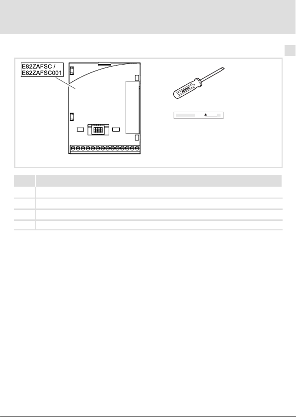
Pos. Lieferumfang
Funktionsmodul E82ZAFSC / E82ZAFSC001
Schraubendreher
Aufkleber
Montageanleitung
EDK82ZAFSC DE/EN/FR 5.0
E82ZAFS002A / E82ZAFX019
11
Page 12
3 Produktbeschreibung
APPLICATION
010 / 3A22
Identifikation
Identifikation
APPLICATION
010/ 3A22
Produktreihe
STANDARD−I/O
Gerätegeneration
Variante
000: Standard
001: verlackte Leiterplatten
Hardwarestand
L
Type
Id.-No.
Prod.-No.
Ser.-No.
E82AF000P0B201XX
E82ZAFX005
E82ZAF S C 00x 3A
12
EDK82ZAFSC DE/EN/FR 5.0
Page 13

Technische Daten
Anschlussdaten
4 Technische Daten
Anschlussdaten
X3/ Werte
62 Auflösung: 10 Bit
Linearitätsfehler: ±0.5 %
Temperaturfehler: 0.3 % (0 +60°C)
Belastbarkeit I
8
Auflösung: 10 Bit
Linearitätsfehler: ±0.5 %
Temperaturfehler: 0.3 % (0 +60 °C)
Eingangswiderstand
l R
Eingang
l R
9 Belastbarkeit I
7 potenzialgetrennt zu Klemme X3/39 (GND2)
20
28
E1
E2
E3
E4
39 potenzialgetrennt zu Klemme X3/7 (GND1)
A1 Belastbarkeit:
1)
Eingang
Belastbarkeit: S I
Eingangswiderstand: 3.3 kW
1)
1)
1 = HIGH (+12 +30 V), SPS−Pegel, HTL
0 = LOW (0 +3 V), SPS−Pegel, HTL
I
= 10 mA, bei interner Versorgung
max
I
= 50 mA, bei externer Versorgung
max
Wahlweise Frequenzeingang 0 10 kHz einspurig oder 0 ... 1 kHz zweispurig, Konfig. über C0425
Einsatzbedingungen
Umgebungsbedingungen
Klimatisch
Lagerung IEC/EN 60721−3−1 1K3 (−25 ... +60 °C)
Transport IEC/EN 60721−3−2 2K3 (−25 ... +70 °C)
Betrieb Entsprechend der Daten des verwendeten Lenze Grundgerätes (siehe
Verschmutzung EN 61800−5−1 Verschmutzungsgrad 2
= 2 mA
max
> 50 kW (bei Spannungssignal)
= 250 W (bei Stromsignal)
= 10 mA
max
= 40 mA
max
Dokumentation des Grundgerätes).
4
EDK82ZAFSC DE/EN/FR 5.0
13
Page 14
4 Technische Daten
Abmessungen
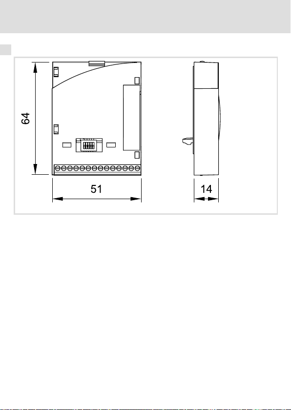
Abmessungen
alle Maße in mm
E82ZAFS002A
14
EDK82ZAFSC DE/EN/FR 5.0
Page 15

Mechanische Installation 5
5 Mechanische Installation
Folgen Sie zur mechanischen Installation des Funktionsmoduls den Hinweisen in der Montageanleitung des Grundgerätes.
Die Montageanleitung des Grundgerätes ...
ƒ ist Teil des Lieferumfangs und liegt jedem Gerät bei.
ƒ gibt Hinweise, um Beschädigungen durch unsachgemäße Behandlung zu vermeiden.
ƒ beschreibt die einzuhaltende Reihenfolge der Installationsschritte.
EDK82ZAFSC DE/EN/FR 5.0
15
Page 16

6 Elektrische Installation
EMV−gerechte Verdrahtung
6 Elektrische Installation
EMV−gerechte Verdrahtung
Für eine EMV−gerechte Verdrahtung beachten Sie folgende Punkte:
Hinweis!
ƒ Steuerleitungen getrennt von Motorleitungen verlegen.
ƒ Schirme so weit wie möglich an die Klemmen führen (ungeschirmte
Aderlänge < 40 mm).
ƒ Legen Sie die Schirme der Steuerleitungen bzw. Datenleitungen wie folgt
auf:
– Einseitig am Umrichter bei Leitungen mit analogen Signalen.
– Beidseitig bei Leitungen mit digitalen Signalen.
ƒ Beachten Sie die weiteren Hinweise zur EMV−gerechten Verdrahtung in der
Dokumentation des Grundgerätes.
16
EDK82ZAFSC DE/EN/FR 5.0
Page 17
Elektrische Installation
Verdrahtung
Daten der Anschlussklemmen
Bereich Werte
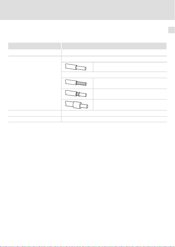
Elektrischer Anschluss Klemmenleiste mit Schraubanschluss
Anschlussmöglichkeiten
Anzugsmoment 0.22 ... 0.25 Nm (1.9 ... 2.2 lb−in)
Abisolierlänge 5 mm
starr:
flexibel:
2
1.5 mm
(AWG 16)
ohne Aderendhülse
2
1.0 mm
(AWG 18)
mit Aderendhülse, ohne Kunststoffhülse
2
0.5 mm
(AWG 20)
mit Aderendhülse, mit Kunststoffhülse
2
0.5 mm
(AWG 20)
Verdrahtung
6
EDK82ZAFSC DE/EN/FR 5.0
17
Page 18
6 Elektrische Installation
Verdrahtung
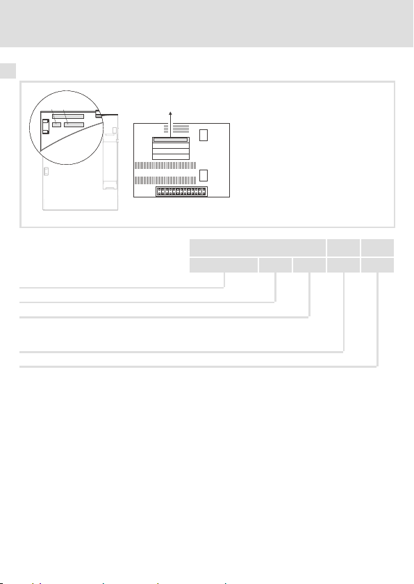
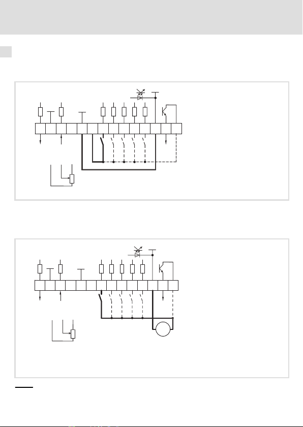
Versorgung über die interne Spannungsquelle (X3/20):
ƒ X3/28, Reglersperre (CINH)
ƒ X3/E1 .... X3/E4, digitale Eingänge
GND2
X3
GND1
62 8
AOUT1
GND1
+5V
77
AIN1
7
+20V
20 28
9
8
9
1k … 10k
0 … +5 V
E1 E2E3E439A1
Versorgung über eine externe Spannungsquelle:
ƒ X3/28, Reglersperre (CINH)
ƒ X3/E1 ... X3/E4, digitale Eingänge
GND2
GND1
6278 9 20 28E1E2 E3 E4 39 A1 59
X3
AOUT1
Für den Betrieb notwendige Mindestverdrahtung
AIN1
897
0…+5V
+5V
GND1
+20V
7
1k … 10k
DIGOUT1
_
24 V ext.
(+12VDC-0%
+30VDC+0%,
max. 120 mA)
59
DIGOUT1
E82ZAFS004
+
...
E82ZAFS005
18
EDK82ZAFSC DE/EN/FR 5.0
Page 19
Elektrische Installation
Verdrahtung
6
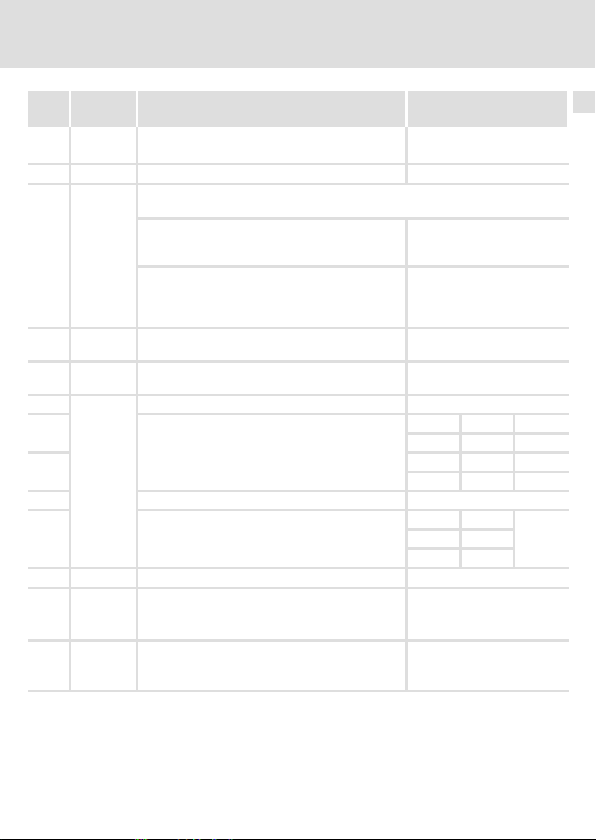
X3/ Signaltyp Funktion
62 Analoger
Ausgang
7 − GND1, Bezugspotenzial für analoge Signale −
8 Analoger
Eingang
9 − Interne, stabilisierte DC−Spannungsquelle für
20 − Interne DC−Spannungsquelle zum Ansteuern der
28
3)
E1
3)
E2
Digitale
Eingänge
E3 Gleichstrombremse (DCB) 1 = DCB
E4 Drehrichtungsumkehr
39 − GND2, Bezugspotenzial für digitale Signale −
A1 Digitaler
Ausgang
59 − DC−Versorgung für X3/A1
1)
Ausgangspegel 0 +10 V: Offset (C0109/C0422) und Verstärkung (C0108/C0420) anpassen
2)
Offset (C0026) und Verstärkung (C0027) für jedes Funktionsmodul separat abgleichen ...
− nach Austausch des Funktionsmoduls oder des Grundgerätes.
− nach Laden der Lenze−Einstellung.
3)
Wahlweise Frequenzeingang 0 10 kHz einspurig oder 0 ... 1 kHz zweispurig, Konfig. über C0425
(Lenze−Einstellung: Fettdruck)
Ausgangsfrequenz 0 +6 V
Eingang für Istwert oder Sollwert
Bereich umschalten mit DIP−Schalter und in C0034:
l Spannungssignal
l Stromsignal
Sollwertpotenziometer
digitalen Eingänge und Ausgänge
Reglersperre (CINH) 1 = Freigabe
Aktivierung von Festfrequenzen (JOG)
JOG1 = 20 Hz
JOG2 = 30 Hz
JOG3 = 40 Hz
Rechts−/Linkslauf (CW/CCW)
Betriebsbereit
l interne Versorgung:
l externe Versorgung:
l intern (Brücke zu X3/20):
l extern:
Pegel
(Lenze−Einstellung: Fettdruck)
1)
0 +10 V
0 +5 V
0 +10 V
−10 +10 V
0 +20 mA
+4 +20 mA
+4 +20 mA (drahtbruchüberwacht)
+5.2 V
+20 V ±10 % (Bezug: X3/7)
JOG1 1 0
JOG2 0 1
JOG3 1 1
CW 0
CCW 1
0 +20 V
0 +24 V
+20 V
+24 V
2)
E1 E2
E4
EDK82ZAFSC DE/EN/FR 5.0
19
Page 20

7 Inbetriebnahme
Vor dem ersten Einschalten
7 Inbetriebnahme
Vor dem ersten Einschalten
Hinweis!
ƒ Wenn Sie die Inbetriebnahme mit einer von der Lenze−Einstellung
abweichenden Konfiguration durchführen, lesen Sie die Anweisungen
"Individuelle Einstellungen" (22).
ƒ Achten Sie darauf,
– dass Sie mit dem DIP−Schalter am Funktionsmodul den Sollwertbereich
richtig eingestellt haben (21).
– dass C0034 an die Einstellung des DIP−Schalters angepasst ist (21).
Beispiel: Sollwertvorgabe (0 V ... +5 V) über Potenziometer an X3/7,
X3/8 und X3/9
ð C0034 = 0, DIP−Schalter 1, 2, 4 und 5 = OFF, 3 = ON
20
EDK82ZAFSC DE/EN/FR 5.0
Page 21

Inbetriebnahme
DIP−Schalterstellung
DIP−Schalterstellung
ON
1ON234
5
OFF
Hinweis!
ƒ Die DIP−Schalter und C0034 unbedingt auf den gleichen Bereich einstellen,
da sonst das analoge Eingangssignal an X3/8 durch das Grundgerät falsch
interpretiert wird.
ƒ Wird ein Sollwertpotenziometer intern über X3/9 versorgt, unbedingt die
DIP−Schalter auf den Spannungsbereich 0 ... 5 V einstellen. Andernfalls
kann nicht der ganze Drehzahlbereich durchfahren werden.
7
Signal an X3/8
1 2 3 4 5
0 ... 5 V OFF OFF ON OFF OFF 0
0 ... 10 V (Lenze−Einstellung) OFF OFF ON OFF ON 0
0 ... 20 mA OFF OFF ON ON OFF 0
4 ... 20 mA OFF OFF ON ON OFF 1
4 ... 20 mA (drahtbruchüberwacht) OFF OFF ON ON OFF 3
−10 ... +10 V ON ON OFF OFF OFF 2
EDK82ZAFSC DE/EN/FR 5.0
Schalterstellung
C0034
21
Page 22

7 Inbetriebnahme
Inbetriebnahmeschritte
Inbetriebnahmeschritte
Schritt Vorgehensweise Beschreibung
1. Netzspannung zuschalten. Das Grundgerät ist nach ca. 1 Sekunde betriebsbereit.
2. Digitale Eingänge ansteuern.
3. Sollwert vorgeben Lenze−Einstellung:
4. Regler über Klemme freigeben.
5. Der Antrieb läuft jetzt.
Die Reglersperre ist aktiv.
Reaktion des Grundgerätes:
Die grüne LED blinkt.
Keypad: (falls aufgesteckt)
Lenze−Einstellung:
l Rechtslauf:
– E1, E2, E3, E4: LOW
l Linkslauf:
– E1, E2, E3: LOW
– E4: HIGH
Individuelle Einstellung:
l Digitale Eingänge über C0007 oder C0410 anpassen.
l Digitale Eingänge so ansteuern, dass der Antrieb nach
Reglerfreigabe über Klemme anlaufen kann.
Sollwert: 0 ... +10 V
Individuelle Einstellung:
l Jenach Stellung des DIP−Schalters am Funktionsmodul
– Leitstrom an X3/8 anlegen oder
– Leitspannung an X3/8 anlegen.
l C0034 überprüfen.
Lenze−Einstellung:
X3/28 = HIGH (+12 ... +30 V)
Reaktion des Grundgerätes:
l Die grüne LED leuchtet.
l Keypad: erlischt.
22
EDK82ZAFSC DE/EN/FR 5.0
Page 23

Inbetriebnahme
Inbetriebnahmeschritte
Hinweis!
Das Grundgerät ist nur funktionsfähig, wenn ein HIGH−Pegel an X3/28 anliegt
(Reglerfreigabe über Klemme).
ƒ Beachten Sie, dass die Reglersperre über mehrere Quellen gesetzt werden
kann. Die Quellen wirken wie eine Reihenschaltung von Schaltern.
ƒ Wenn der Antrieb trotz Reglerfreigabe über X3/28 nicht anläuft,
überprüfen Sie, ob noch über eine andere Quelle die Reglersperre gesetzt
ist. Eine andere Quelle könnte die −Taste des Keypad sein.
7
EDK82ZAFSC DE/EN/FR 5.0
23
Page 24

Legend for fold−out page
Pos. Description Detailed
Function module E82ZAFSC / E82ZAFSC001
Switch for the configuration of the analog input (terminal X3/8) 41
Digital and analog inputs and outputs, terminal strip X3 39
Nameplate 32
0Fig. 0Tab. 0
information
24
EDK82ZAFSC DE/EN/FR 5.0
Page 25

Contents i
1 About this documentation 26 . . . . . . . . . . . . . . . . . . . . . . . . . . . . . . . . . . . . . . . . . . .
Conventions used 27 . . . . . . . . . . . . . . . . . . . . . . . . . . . . . . . . . . . . . . . . . . . . . . . . . .
Notes used 28 . . . . . . . . . . . . . . . . . . . . . . . . . . . . . . . . . . . . . . . . . . . . . . . . . . . . . . . .
2 Safety instructions 29 . . . . . . . . . . . . . . . . . . . . . . . . . . . . . . . . . . . . . . . . . . . . . . . . .
3 Product description 30 . . . . . . . . . . . . . . . . . . . . . . . . . . . . . . . . . . . . . . . . . . . . . . . . .
Function 30 . . . . . . . . . . . . . . . . . . . . . . . . . . . . . . . . . . . . . . . . . . . . . . . . . . . . . . . . .
Application as directed 30 . . . . . . . . . . . . . . . . . . . . . . . . . . . . . . . . . . . . . . . . . . . . . .
Scope of supply 31 . . . . . . . . . . . . . . . . . . . . . . . . . . . . . . . . . . . . . . . . . . . . . . . . . . . .
Identification 32 . . . . . . . . . . . . . . . . . . . . . . . . . . . . . . . . . . . . . . . . . . . . . . . . . . . . . .
4 Technical data 33 . . . . . . . . . . . . . . . . . . . . . . . . . . . . . . . . . . . . . . . . . . . . . . . . . . . . .
Connection data 33 . . . . . . . . . . . . . . . . . . . . . . . . . . . . . . . . . . . . . . . . . . . . . . . . . . .
Operating conditions 33 . . . . . . . . . . . . . . . . . . . . . . . . . . . . . . . . . . . . . . . . . . . . . . .
Dimensions 34 . . . . . . . . . . . . . . . . . . . . . . . . . . . . . . . . . . . . . . . . . . . . . . . . . . . . . . .
5 Mechanical installation 35 . . . . . . . . . . . . . . . . . . . . . . . . . . . . . . . . . . . . . . . . . . . . .
6 Electrical installation 36 . . . . . . . . . . . . . . . . . . . . . . . . . . . . . . . . . . . . . . . . . . . . . . .
Wiring according to EMC 36 . . . . . . . . . . . . . . . . . . . . . . . . . . . . . . . . . . . . . . . . . . . .
Wiring 37 . . . . . . . . . . . . . . . . . . . . . . . . . . . . . . . . . . . . . . . . . . . . . . . . . . . . . . . . . . .
7 Commissioning 40 . . . . . . . . . . . . . . . . . . . . . . . . . . . . . . . . . . . . . . . . . . . . . . . . . . . .
Before switching on 40 . . . . . . . . . . . . . . . . . . . . . . . . . . . . . . . . . . . . . . . . . . . . . . . .
DIP switch position 41 . . . . . . . . . . . . . . . . . . . . . . . . . . . . . . . . . . . . . . . . . . . . . . . . .
Commissioning steps 42 . . . . . . . . . . . . . . . . . . . . . . . . . . . . . . . . . . . . . . . . . . . . . . .
EDK82ZAFSC DE/EN/FR 5.0
25
Page 26

1 About this documentation
1 About this documentation
Contents
This documentation includes ...
ƒ Information about the mechanical and electrical installation of the function module;
ƒ Information about the commissioning of the function module;
ƒ Safety instructions which you must observe in any case;
ƒ Data about the versions of Lenze basic devices to be used;
ƒ Technical data.
Validity information
The information given in this documentation is valid for the following devices:
Function module Type designation As of hardware version
STANDARD I/O E82ZAFSC 3A
STANDARD I/O (coated) E82ZAFSC001 3A
Target group
This documentation is directed at persons who install and commission the described
product according to the project requirements.
Tip!
Documentation and software updates for further Lenze products can be found
on the Internet in the "Services & Downloads" area under
http://www.Lenze.com
26
EDK82ZAFSC DE/EN/FR 5.0
Page 27

About this documentation
Conventions used
Conventions used
This documentation uses the following conventions to distinguish between different types
of information:
Type of information Identification Examples/notes
Numbers
Decimal separator Point The decimal point is used throughout
Symbols
Page reference
this documentation.
Example: 1234.56
Reference to another page with
additional information
Example: 16 = see page 16
1
EDK82ZAFSC DE/EN/FR 5.0
27
Page 28

1 About this documentation
Notes used
Notes used
The following pictographs and signal words are used in this documentation to indicate
dangers and important information:
Safety instructions
Structure of safety instructions:
Danger!
(characterises the type and severity of danger)
Note
(describes the danger and gives information about how to prevent dangerous
situations)
Pictograph and signal word Meaning
Danger of personal injury through dangerous electrical
Danger!
Danger!
Stop!
Application notes
Pictograph and signal word Meaning
voltage.
Reference to an imminent danger that may result in death
or serious personal injury if the corresponding measures are
not taken.
Danger of personal injury through a general source of
danger.
Reference to an imminent danger that may result in death
or serious personal injury if the corresponding measures are
not taken.
Danger of property damage.
Reference to a possible danger that may result in property
damage if the corresponding measures are not taken.
Note!
Tip!
28
Important note to ensure troublefree operation
Useful tip for simple handling
Reference to another documentation
EDK82ZAFSC DE/EN/FR 5.0
Page 29

Safety instructions 2
2 Safety instructions
Danger!
Inappropriate handling of the function module and the basic device can cause
serious injuries to persons and damage to material assets.
Observe the safety instructions and residual hazards included in the
documentation of the basic device.
Stop!
Electrostatic discharge
Electronic components within the function module can be damaged or
destroyed by electrostatic discharge.
Possible consequences:
ƒ The function module is defective.
Protective measures
ƒ Free yourself from any electrostatic charge before you touch the module.
EDK82ZAFSC DE/EN/FR 5.0
29
Page 30

3 Product description
Function
3 Product description
Function
The function module allows the control of Lenze frequency inverters and the Lenze Drive
PLC with analog and digital control signals.
Application as directed
The function module ...
ƒ is an accessories unit which can be used with the following Lenze basic devices:
Function module
E82ZAFSC
E82ZAFSC001 Frequency inverter 8200 motec Vx14
ƒ is an equipment to be used in industrial power systems.
ƒ allows for the control of Lenze frequency inverters and the Lenze Drive PLC with
analog and digital control signals.
Any other use shall be deemed inappropriate!
Lenze basic devices
Product range Product name As of hardware version
Frequency inverter 8200 vector Vx14
Drive PLC Drive PLC 1x20
30
EDK82ZAFSC DE/EN/FR 5.0
Page 31

Scope of supply
Product description
Scope of supply
3
Pos. Scope of supply
Function module E82ZAFSC / E82ZAFSC001
Screw driver
Sticker
Mounting Instructions
EDK82ZAFSC DE/EN/FR 5.0
E82ZAFS002A / E82ZAFX019
31
Page 32

3 Product description
APPLICATION
010 / 3A22
Identification
Identification
APPLICATION
010/ 3A22
Product range
STANDARD I/O
Generation
Variant
000: standard
001: coated PCBs
Hardware version
L
Type
Id.-No.
Prod.-No.
Ser.-No.
E82AF000P0B201XX
E82ZAFX005
E82ZAF s c 00x 3A
32
EDK82ZAFSC DE/EN/FR 5.0
Page 33

Technical data
Connection data
4 Technical data
Connection data
X3/ Values
62 Resolution: 10 bit
Linearity distortion: ±0.5 %
Temperature distortion: 0.3 % (0 +60°C)
Carrying capacity I
8
Resolution: 10 bit
Linearity distortion: ±0.5 %
Temperature distortion: 0.3 % (0 +60 °C)
Input resistance
l R
> 50 kW (with voltage signal)
Input
l R
= 250 W (with current signal)
9 Carrying capacity I
7 isolated from terminal X3/39 (GND2)
20
28
E1
E2
E3
E4
39 isolated from terminal X3/7 (GND1)
A1 Load capacity:
1)
Input
Load capacity: S I
Input resistance: 3.3 kW
1)
1)
1 = HIGH (+12 +30 V), PLC level, HTL
0 = LOW (0 +3 V), PLC level, HTL
I
= 10 mA, with internal supply
max
I
= 50 mA, with external supply
max
Frequency input alternatively 0 10 kHz single−track or 0 ... 1 kHz two−track, config. via C0425
Operating conditions
Ambient conditions
Climate
Storage IEC/EN 60721−3−1 1K3 (−25 to +60 °C)
Transport IEC/EN 60721−3−2 2K3 (−25 to +70 °C)
Operation Corresponding to the data of the Lenze basic device used (see
Pollution EN 61800−5−1 Degree of pollution 2
= 2 mA
max
= 10 mA
max
= 40 mA
max
documentation of the basic device).
4
EDK82ZAFSC DE/EN/FR 5.0
33
Page 34

4 Technical data
Dimensions
Dimensions
All dimensions in mm
E82ZAFS002A
34
EDK82ZAFSC DE/EN/FR 5.0
Page 35

Mechanical installation 5
5 Mechanical installation
Follow the notes given in the Mounting Instructions for the standard device for the
mechanical installation of the function module.
The Mounting Instructions for the standard device ...
ƒ are part of the scope of supply and are enclosed with each device.
ƒ provide tips for avoiding damage through improper handling.
ƒ describe the obligatory order of installation steps.
EDK82ZAFSC DE/EN/FR 5.0
35
Page 36

6 Electrical installation
Wiring according to EMC
6 Electrical installation
Wiring according to EMC
Please observe the following for wiring according to EMC guidelines:
Note!
ƒ Separate control cables from motor cables.
ƒ Lead the shields as far as possible to the terminals (unshielded core length
< 40 mm).
ƒ Connect control and data cable shields as follows:
– Analog signal cable shields must be connected with one end at the
inverter.
– Digital signal cable shields must be connected with both ends.
ƒ More information about wiring according to EMC guidelines can be
obtained from the corresponding documentation for the standard device.
36
EDK82ZAFSC DE/EN/FR 5.0
Page 37

Electrical installation
Wiring
Terminal data
Range Values
Electrical connection Terminal strip with screw connection
Possible connections
Tightening torque 0.22 ... 0.25 Nm (1.9 ... 2.2 lb−in)
Bare end 5 mm
rigid:
flexible:
2
1.5 mm
(AWG 16)
without wire end ferrule
2
1.0 mm
(AWG 18)
with wire end ferrule, without plastic sleeve
2
0.5 mm
(AWG 20)
with wire end ferrule, with plastic sleeve
2
0.5 mm
(AWG 20)
Wiring
6
EDK82ZAFSC DE/EN/FR 5.0
37
Page 38

6 Electrical installation
Wiring
Supply via the internal voltage source (X3/20):
ƒ X3/28, controller inhibit (CINH)
ƒ X3/E1 .... X3/E4, digital inputs
GND2
X3
GND1
62 8
AOUT1
GND1
+5V
77
AIN1
7
+20V
20 28
9
8
9
1k … 10k
0 … +5 V
E1 E2E3E439A1
Supply via an external voltage source:
ƒ X3/28, controller inhibit (CINH)
ƒ X3/E1 ... X3/E4, digital inputs
GND1
6278 9 20 28E1E2 E3 E4 39 A1 59
X3
AOUT1
The min. wiring requirements for operation
AIN1
897
0…+5V
+5V
GND1
+20V
7
1k … 10k
59
DIGOUT1
GND2
DIGOUT1
_
+
24 V ext.
(+12VDC-0%
...
+30VDC+0%,
max. 120 mA)
E82ZAFS004
E82ZAFS005
38
EDK82ZAFSC DE/EN/FR 5.0
Page 39

Electrical installation
Wiring
6
X3/ Signal
type
62 Analog
output
7 − GND1, Reference potential for analog signals −
8 Analog
input
9 − Internal, stabilised DC voltage source for the
20 − Internal DC voltage supply for control of digital
28
3)
E1
3)
E2
Digital
inputs
E3 DC−injection brake (DCB) 1 = DCB
E4 Change of direction of rotation
39 − GND2, Reference potential for digital signals −
A1 Digital
output
59 − DC supply for X3/A1
1)
Output level 0 +10 V: Adapt offset (C0109/C0422) and gain (C0108/C0420)
2)
Adjust offset (C0026) and gain (C0027) separately for each function module ...
− after replacing the function module or the basic device.
− after loading the Lenze setting.
3)
Frequency input alternatively 0 10 kHz single−track or 0 ... 1 kHz two−track, config. via C0425
Function
(Lenze setting: bold print)
Output frequency 0 +6 V
Input for actual value or setpoint
Switch over the range with the DIP switch and in C0034:
l Voltage signal
l Current signal
setpoint potentiometer
inputs and outputs
Controller inhibit (CINH) 1 = enable
Activation of JOG frequencies
JOG1 = 20 Hz
JOG2 = 30 Hz
JOG3 = 40 Hz
CW/CCW rotation
Ready for operation
l internal supply:
l external supply:
l internal (bridge to X3/20):
l external:
Level
(Lenze setting: bold print)
0 +10 V
0 +5 V
0 +10 V
−10 +10 V
0 +20 mA
+4 +20 mA
+4 +20 mA (open−circuit
monitored)
+5.2 V
+20 V ±10 % (ref.: X3/7)
JOG1 1 0
JOG2 0 1
JOG3 1 1
CW 0
CCW 1
0 +20 V
0 +24 V
+20 V
+24 V
1)
2)
e1 E2
E4
EDK82ZAFSC DE/EN/FR 5.0
39
Page 40

7 Commissioning
Before switching on
7 Commissioning
Before switching on
Note!
ƒ If you carry out the commissioning with a configuration different from the
Lenze setting, read the instructions on "Individual Settings" (42).
ƒ Make sure
– that you have correctly set the setpoint range with the DIP switch on
the function module (41).
– that C0034 is adjusted to the settings of the DIP switch (41).
Example: setpoint selection (0 V ... +5 V) via potentiometer at X3/7,
X3/8 and X3/9
ð C0034 = 0, DIP switch 1, 2, 4 and 5 = OFF, 3 = ON
40
EDK82ZAFSC DE/EN/FR 5.0
Page 41

Commissioning
DIP switch position
DIP switch position
ON
1ON234
5
OFF
Note!
ƒ Make sure to set the DIP switch and C0034 to the same range, otherwise
the analog input signal at X3/8 will be interpreted incorrectly by the basic
device.
ƒ If a setpoint potentionmeter is supplied internally via X3/9, make sure to
set the DIP switch to the voltage range 0 ... 5 V. Otherwise it will be
impossible to cover the entire speed range.
7
Signal at X3/8
1 2 3 4 5
0 ... 5V OFF OFF ON OFF OFF 0
0 ... 10 V (Lenze setting) OFF OFF ON OFF ON 0
0 ... 20 mA OFF OFF ON ON OFF 0
4 ... 20 mA OFF OFF ON ON OFF 1
4 ... 20 mA (open−circuit monitored) OFF OFF ON ON OFF 3
−10 ... +10 V ON ON OFF OFF OFF 2
EDK82ZAFSC DE/EN/FR 5.0
Switch position
C0034
41
Page 42

7 Commissioning
Commissioning steps
Commissioning steps
Step Procedure Description
1. Switch on the mains
voltage.
2. Control digital inputs. Lenze setting:
3. Provide a setpoint Lenze setting:
4. Release the controller via
the terminal.
5. The drive should be running now.
The basic device will be ready for operation after approx.
1 second.
The controller inhibit is active.
Drive response:
The green LED is blinking.
Keypad: (if attached)
l CW rotation:
– E1, E2, E3, E4: LOW
l CCW rotation:
– E1, E2, E3: LOW
– E4: HIGH
Individual setting:
l Adapt digital inputs under C0007 or C0410.
l The digital inputs must be controlled so that the drive
can start via terminal after controller enable.
Setpoint: 0 ... +10 V
Individual setting:
l Depending on the position of the DIP switch at the
function module
– apply master current to X3/8 or
– Apply master voltage at X3/8.
l Check C0034.
Lenze setting:
X3/28 = HIGH (+12 ... +30 V)
Drive response:
l The green LED is on.
l Keypad: goes off.
42
EDK82ZAFSC DE/EN/FR 5.0
Page 43

Commissioning
Commissioning steps
Note!
The basic device is only functioning if a HIGH level is applied to X3/28
(controller release via terminal).
ƒ Please observe that the controller can be inhibited through various
sources. All sources act like a series connection of switches.
ƒ If the drive does not start in spite of the controller release via X3/28, check
if the controller inhibit is set via another source. Another source could be
the key of the keypad.
7
EDK82ZAFSC DE/EN/FR 5.0
43
Page 44

Légende de l’illustration de la page dépliante
Pos. Description Informations
Module de fonction E82ZAFSC / E82ZAFSC001
Interrupteur pour la configuration de l’entrée analogique (borne X3/8) 62
Entrées et sorties numériques et analogiques, bornier X3 60
Plaque signalétique 53
0Fig. 0Tab. 0
détaillées
44
EDK82ZAFSC DE/EN/FR 5.0
Page 45

Sommaire i
1 Présentation du document 46 . . . . . . . . . . . . . . . . . . . . . . . . . . . . . . . . . . . . . . . . . . .
Conventions utilisées 47 . . . . . . . . . . . . . . . . . . . . . . . . . . . . . . . . . . . . . . . . . . . . . . .
Remarques utilisées 48 . . . . . . . . . . . . . . . . . . . . . . . . . . . . . . . . . . . . . . . . . . . . . . . .
2 Consignes de sécurité 50 . . . . . . . . . . . . . . . . . . . . . . . . . . . . . . . . . . . . . . . . . . . . . . .
3 Description du produit 51 . . . . . . . . . . . . . . . . . . . . . . . . . . . . . . . . . . . . . . . . . . . . . .
Fonction 51 . . . . . . . . . . . . . . . . . . . . . . . . . . . . . . . . . . . . . . . . . . . . . . . . . . . . . . . . .
Utilisation conforme à la fonction 51 . . . . . . . . . . . . . . . . . . . . . . . . . . . . . . . . . . . . .
Equipement livré 52 . . . . . . . . . . . . . . . . . . . . . . . . . . . . . . . . . . . . . . . . . . . . . . . . . . .
Identification 53 . . . . . . . . . . . . . . . . . . . . . . . . . . . . . . . . . . . . . . . . . . . . . . . . . . . . . .
4 Spécifications techniques 54 . . . . . . . . . . . . . . . . . . . . . . . . . . . . . . . . . . . . . . . . . . .
Données de raccordement 54 . . . . . . . . . . . . . . . . . . . . . . . . . . . . . . . . . . . . . . . . . . .
Conditions d’utilisation 54 . . . . . . . . . . . . . . . . . . . . . . . . . . . . . . . . . . . . . . . . . . . . .
Encombrements 55 . . . . . . . . . . . . . . . . . . . . . . . . . . . . . . . . . . . . . . . . . . . . . . . . . . .
5 Installation mécanique 56 . . . . . . . . . . . . . . . . . . . . . . . . . . . . . . . . . . . . . . . . . . . . . .
6 Installation électrique 57 . . . . . . . . . . . . . . . . . . . . . . . . . . . . . . . . . . . . . . . . . . . . . . .
Câblage conforme CEM 57 . . . . . . . . . . . . . . . . . . . . . . . . . . . . . . . . . . . . . . . . . . . . . .
Câblage 58 . . . . . . . . . . . . . . . . . . . . . . . . . . . . . . . . . . . . . . . . . . . . . . . . . . . . . . . . . .
7 Mise en service 61 . . . . . . . . . . . . . . . . . . . . . . . . . . . . . . . . . . . . . . . . . . . . . . . . . . . .
Avant la première mise sous tension 61 . . . . . . . . . . . . . . . . . . . . . . . . . . . . . . . . . . .
Position d’interrupteur DIP 62 . . . . . . . . . . . . . . . . . . . . . . . . . . . . . . . . . . . . . . . . . . .
Etapes de mise en service 63 . . . . . . . . . . . . . . . . . . . . . . . . . . . . . . . . . . . . . . . . . . . .
EDK82ZAFSC DE/EN/FR 5.0
45
Page 46

1 Présentation du document
1 Présentation du document
Contenu
La présente documentation contient ...
ƒ des informations sur l’installation mécanique et électrique du module de fonction ;
ƒ des informations sur la mise en service du module de fonction ;
ƒ des consignes de sécurité à respecter impérativement ;
ƒ les valeurs indiquées concernant les versions des appareils de base Lenze à utiliser ;
ƒ les spécifications techniques.
Informations relatives à la validité
Les informations contenues dans le présent document s’appliquent aux appareils suivants :
Module de fonction Référence de commande à partir de la version matérielle
E/S STANDARD E82ZAFSC 3A
E/S STANDARD(variante vernie) E82ZAFSC001 3A
Groupe cible
Ce document est destiné aux personnes chargées d’installer et de mettre en service le
produit décrit selon les exigences du projet.
Conseil !
Les mises à jour de logiciels et les documentations relatives aux produits Lenze
sont disponibles dans la zone "Téléchargements" du site Internet :
http://www.Lenze.com
46
EDK82ZAFSC DE/EN/FR 5.0
Page 47

Présentation du document
Conventions utilisées
Conventions utilisées
Pour faire la distinction entre différents types d’informations, ce document utilise les
conventions suivantes :
Type d’information Marquage Exemples/remarques
Représentation des chiffres
Séparateur décimal Point Le point décimal est généralement
Symboles
Renvoi à une page
utilisé.
Exemple : 1234.56
Renvoi à une autre page présentant
des informations supplémentaires
Exemple : 16 = voir page 16
1
EDK82ZAFSC DE/EN/FR 5.0
47
Page 48

1 Présentation du document
Remarques utilisées
Remarques utilisées
Pour indiquer des risques et des informations importantes, la présente documentation
utilise les mots et symboles suivants :
Consignes de sécurité
Présentation des consignes de sécurité
Danger !
(Le pictogramme indique le type de risque.)
Explication
(L’explication décrit le risque et les moyens de l’éviter.)
Pictogramme et mot associé Explication
Situation dangereuse pour les personnes en raison d’une
tension électrique élevée
Danger !
Danger !
Stop !
Indication d’un danger imminent qui peut avoir pour
conséquences des blessures mortelles ou très graves en cas
de non−respect des consignes de sécurité correspondantes
Situation dangereuse pour les personnes en raison d’un
danger d’ordre général
Indication d’un danger imminent qui peut avoir pour
conséquences des blessures mortelles ou très graves en cas
de non−respect des consignes de sécurité correspondantes
Risques de dégâts matériels
Indication d’un risque potentiel qui peut avoir pour
conséquences des dégâts matériels en cas de non−respect
des consignes de sécurité correspondantes
48
EDK82ZAFSC DE/EN/FR 5.0
Page 49

Consignes d’utilisation
Pictogramme et mot associé Explication
Présentation du document
Remarques utilisées
1
Remarque
importante !
Conseil !
Remarque importante pour assurer un fonctionnement
correct
Conseil utile pour faciliter la mise en oeuvre
Référence à une autre documentation
EDK82ZAFSC DE/EN/FR 5.0
49
Page 50

2 Consignes de sécurité
2 Consignes de sécurité
Danger !
L’utilisation non conforme à la fonction du module de fonction et de l’appareil
de base peut entraîner de graves dommages corporels et matériels.
Tenir compte des consignes de sécurité et des dangers résiduels énoncés dans
la documentation de l’appareil de base.
Stop !
Décharges électrostatiques
Les décharges électrostatiques peuvent endommager ou détruire les
composants électroniques situés à l’intérieur du module de fonction.
Risques encourus :
ƒ Module de fonction en panne
Mesures de protection
ƒ Avant d’entrer en contact avec le module, veillez à vous libérer de toute
charge électrostatique.
50
EDK82ZAFSC DE/EN/FR 5.0
Page 51

Description du produit
Fonction
3 Description du produit
Fonction
Le module de fonction permet le pilotage des convertisseurs de fréquence et des API pour
entraînements Lenze à l’aide de signaux de commande analogiques et numériques.
Utilisation conforme à la fonction
Le module de fonction ...
ƒ est un pack d’accessoires qui peuvent être utilisés avec les appareils de base Lenze
suivants :
Module de fonction
E82ZAFSC
E82ZAFSC001 convertisseurs de
ƒ est un moyen de fonctionnement à utiliser dans les installations industrielles à
courant fort.
ƒ permet la commande de convertisseurs de fréquence de Lenze et d’API pour
entraînements Lenze avec des signaux de commande analogiques et numériques.
Toute autre utilisation est contre−indiquée !
Appareils de base Lenze
Gamme de produits Désignation d’appareil à partir de la version
convertisseurs de
fréquence
API pour entraînements Drive PLC 1x20
fréquence
8200 vector Vx14
8200 motec Vx14
matérielle
3
EDK82ZAFSC DE/EN/FR 5.0
51
Page 52

3 Description du produit
Equipement livré
Equipement livré
Pos. Contenu de l’emballage
Module de fonction E82ZAFSC / E82ZAFSC001
Tournevis
Autocollant
Instructions de montage
E82ZAFS002A / E82ZAFX019
52
EDK82ZAFSC DE/EN/FR 5.0
Page 53

Identification
APPLICATION
010 / 3A22
Description du produit
Identification
3
APPLICATION
010/ 3A22
Gamme de produits
E/S STANDARD
Génération d’appareils
Variante
000 : standard
001 : carte de circuit imprimé vernie
Version matérielle
L
Type
Id.-No.
Prod.-No.
Ser.-No.
E82AF000P0B201XX
E82ZAFX005
E82ZAF S c 00x 3A
EDK82ZAFSC DE/EN/FR 5.0
53
Page 54

4 Spécifications techniques
Données de raccordement
4 Spécifications techniques
Données de raccordement
X3/ Valeurs
62 Résolution : 10 bits
Erreur de linéarité : ±0.5 %
Erreur de température : 0,3 % (0 +60°C)
Charge admissible I
8
Résolution : 10 bits
Erreur de linéarité : ±0.5 %
Erreur de température : 0.3 % (0 +60 °C)
Résistance d’entrée
l R
> 50 kW (signal de tension)
Entrée
l R
= 250 W (signal de courant)
9 Capacité de charge I
7 Avec séparation de potentiel sur la borne X3/39 (GND2)
20
28
E1
E2
E3
E4
39 Avec séparation de potentiel sur la borne X3/7 (GND1)
A1 Charge admissible :
1)
Entrée
Charge admissible : S I
Résistance d’entrée : 3.3 kW
1)
1)
1 = HAUT (+12 +30 V), niveau de l’API, HTL
0 = BAS (0 +3 V), niveau de l’API, HTL
I
= 10 mA, avec alimentation interne
max
I
= 50 mA, avec alimentation externe
max
Au choix : entrée de fréquence 0 10 kHz à une voie ou 0 ... 1 kHz à deux voies, configuration via
C0425
Conditions d’utilisation
Conditions ambiantes
Conditions climatiques
Stockage CEI/EN 60721−3−1 1K3 (−25 ... +60 °C)
Transport CEI/EN 60721−3−2 2K3 (−25 ... +70 °C)
Fonctionnement Conformément aux données de l’appareil de base Lenze utilisé (voir la
Pollution ambiante
admissible
= 2 mA
max
= 10 mA
max
= 40 mA
max
documentation de l’appareil de base).
EN 61800−5−1 Degré de pollution 2
54
EDK82ZAFSC DE/EN/FR 5.0
Page 55

Encombrements
Toutes les cotes en mm
Spécifications techniques
Encombrements
E82ZAFS002A
4
EDK82ZAFSC DE/EN/FR 5.0
55
Page 56

5 Installation mécanique
5 Installation mécanique
Pour l’installation mécanique du module de fonction, suivre les consignes fournies dans les
instructions de montage de l’appareil de base.
Les instructions de montage de l’appareil de base ...
ƒ font partie de la livraison standard et sont comprises dans l’emballage.
ƒ contiennent des consignes pour éviter des dommages dus à un emploi
contre−indiqué.
ƒ décrivent l’ordre à respecter pour les opérations d’installation.
56
EDK82ZAFSC DE/EN/FR 5.0
Page 57

Installation électrique
Câblage conforme CEM
6 Installation électrique
Câblage conforme CEM
Pour réaliser un câblage conforme CEM, respectez les points suivants :
Remarque importante !
ƒ Poser les câbles de commande séparément des câbles moteur.
ƒ Conduire le blindage aussi loin que possible vers les bornes (longueur de fil
sans blindage < 40 mm).
ƒ Pour poser les blindages des câbles de commande ou des lignes de
données, procédez comme suit :
– D’un seul côté du convertisseur pour les câbles avec des signaux
analogiques.
– Des deux côtés pour les câbles avec des signaux numériques.
ƒ Respectez les autres consignes relatives au câblage conforme CEM fournies
dans la documentation de l’appareil de base.
6
EDK82ZAFSC DE/EN/FR 5.0
57
Page 58

6 Installation électrique
Câblage
Câblage
Spécifications des bornes de raccordement
Plage Valeurs
Raccordement électrique Bornier avec fixation par vis
Possibilités de raccordement
Couple de serrage 0,22 à 0,25 Nm (1,9 à 2,2 lb−in)
Longueur du fil dénudé 5 mm
Rigide :
Flexible :
1,5 mm
sans embout
1,0 mm
avec embout, sans cosse en plastique
0,5 mm
avec embout, avec cosse en plastique
0,5 mm
2
(AWG 16)
2
(AWG 18)
2
(AWG 20)
2
(AWG 20)
58
EDK82ZAFSC DE/EN/FR 5.0
Page 59

Alimentation via la source de tension interne (X3/20) :
ƒ X3/28, blocage variateur (CINH)
ƒ X3/E1 .... X3/E4, entrées numériques
GND2
Installation électrique
Câblage
6
X3
GND1
62 8
AOUT1
GND1
+5V
77
AIN1
7
+20V
20 28
9
8
9
1k … 10k
0 … +5 V
E1 E2E3E439A1
DIGOUT1
Alimentation via une source de tension externe :
ƒ X3/28, blocage variateur (CINH)
ƒ X3/E1 ... X3/E4, entrées numériques
GND2
GND1
6278 9 20 28E1E2 E3 E4 39 A1 59
X3
AOUT1
Câblage mini nécessaire au fonctionnement
AIN1
897
0…+5V
+5V
GND1
+20V
7
1k … 10k
DIGOUT1
_
24 V ext.
(+12VDC-0%
+30VDC+0%,
max. 120 mA)
59
E82ZAFS004
+
...
E82ZAFS005
EDK82ZAFSC DE/EN/FR 5.0
59
Page 60

6 Installation électrique
Câblage
X3/ Type de
signal
62 Sortie
analogique
Fonction
(réglage Lenze : en caractères gras)
Fréquence de sortie 0 +6 V
Niveau
(réglage Lenze : en caractères
gras)
0 +10 V
1)
7 − GND1, potentiel de référence pour les signaux analogiques −
8 Entrée
analogique
9 − Source de tension CC interne, stabilisée pour
20 − Source de tension CC interne pour la commande
28
3)
E1
3)
E2
Entrées
numériques
E3 Frein CC (DCB) 1 = DCB
E4 Inversion du sens de rotation
Entrée pour valeur réelle ou consigne
Commutation de plagevia l’interrupteur DIP et dans C0034 :
l Signal de tension
l Signal de courant
potentiomètre de consigne
des entrées et sorties numériques
0 +5 V
0 +10 V
−10 +10 V
0 +20 mA
+4 +20 mA
+4 +20 mA (protection
contre rupture de fil)
+5.2 V
+20 V ±10 % (référence :
X3/7)
Blocage variateur (CINH) 1 = Déblocage
Activation des fréquences fixes (JOG)
JOG1 = 20 Hz
JOG2 = 30 Hz
JOG3 = 40 Hz
Rotation horaire/antihoraire (CW/CCW)
JOG1 1 0
JOG2 0 1
JOG3 1 1
CW 0
CCW 1
39 − GND2, potentiel de référence pour les signaux numériques −
A1 Sortie
numérique
59 − Alimentation CC pour X3/A1
1)
Niveau de sortie 0 +10 V : ajuster le décalage (C0109/C0422) et le gain (C0108/C0420).
2)
Régler séparément le décalage (C0026) et le gain (C0027) pour chaque module de fonction ...
− après le remplacement du module de fonction ou de l’appareil de base.
− après le chargement du réglage Lenze.
3)
Au choix : entrée de fréquence 0 10 kHz à une voie ou 0 ... 1 kHz à deux voies, configuration via C0425
Opérationnel
l Alimentation interne :
l Alimentation externe :
l interne (pont vers X3/20) :
l externe :
0 +20 V
0 +24 V
+20 V
+24 V
2)
E1 E2
E4
60
EDK82ZAFSC DE/EN/FR 5.0
Page 61

Avant la première mise sous tension
7 Mise en service
Avant la première mise sous tension
Remarque importante !
ƒ Si vous effectuez la mise en service avec une configuration différente du
réglage Lenze, lisez les instructions "Réglages individuels" (63).
ƒ Assurez−vous
– que la plage de la consigne est réglée correctement à l’aide de
l’interrupteur DIP au niveau du module de fonction(62).
– que C0034 est adapté au réglage de l’interrupteur DIP (62).
Exemple : réglage de la consigne (0 V ... +5 V) via le potentiomètre au
niveau de X3/7, X3/8 et X3/9
ð C0034 = 0, interrupteurs DIP 1, 2, 4 et 5 = OFF, 3 = ON
Mise en service
7
EDK82ZAFSC DE/EN/FR 5.0
61
Page 62

7 Mise en service
Position d’interrupteur DIP
Position d’interrupteur DIP
ON
1ON234
5
OFF
Remarque importante !
ƒ Régler impérativement l’interrupteur DIP et C0034 sur la même plage ;
dans le cas contraire, le signal d’entrée analogique sur X3/8 sera mal
interprété par l’appareil de base.
ƒ Si un potentiomètre de consigne est alimenté en interne via X3/9, régler
impérativement l’interrupteur DIP sur la plage de tension 0 ... 5 V.
Autrement, la plage de vitesse ne pourra pas être parcourue en entier.
Signal sur X3/8
0 ... 5 V OFF OFF ON OFF OFF 0
0 ... 10 V (réglage Lenze) OFF OFF ON OFF ON 0
0 à 20 mA OFF OFF ON ON OFF 0
4 à 20 mA OFF OFF ON ON OFF 1
4 ... 20 mA (avec contrôle de rupture de
fil)
−10 ... +10 V ON ON OFF OFF OFF 2
OFF OFF ON ON OFF 3
Position interrupteur
1 2 3 4 5
C0034
62
EDK82ZAFSC DE/EN/FR 5.0
Page 63

Mise en service
Etapes de mise en service
Etapes de mise en service
Etape Procédure Description
1. Brancher la tension réseau. Le convertisseur est prêt à fonctionner après env. 1 s.
2. Activer les entrées
numériques.
3. Entrer la consigne Réglage Lenze :
4. Débloquer le variateur via
la borne.
5. L’entraînement fonctionne.
Le blocage variateur est activé.
Réaction de l’appareil de base :
La LED verte clignote.
Clavier de commande : (le cas échéant)
Réglage Lenze :
l Rotation horaire :
– E1, E2, E3, E4 : LOW (BAS)
l Rotation antihoraire :
– E1, E2, E3 : LOW (BAS)
– E4 : HIGH(HAUT)
Réglage individuel :
l Adapter les entrées numériques via C0007 ou C0410.
l Activer les entrées numériques de sorte que le variateur
puisse se mettre en marche après le déblocage du
variateur via la borne.
Valeur de consigne : 0 ... +10 V
Réglage individuel :
l Selon la position de l’interrupteur DIP au niveau du
module de fonction
– Générer le courant maître en X3/8 ou
– Appliquer la tension maître sur X3/8.
l Vérifier C0034.
Réglage Lenze :
X3/28 = HIGH (HAUT) (+12 ... +30 V)
Réaction de l’appareil de base :
l La LED verte est allumée.
l Clavier de commande : éteint.
7
EDK82ZAFSC DE/EN/FR 5.0
63
Page 64

7 Mise en service
Etapes de mise en service
Remarque importante !
L’appareil de base ne peut fonctionner que lorsqu’un niveau HAUT est actif sur
la borne X3/28 (déblocage variateur via borne).
ƒ Veillez à ce que le blocage variateur puisse être défini par le biais de
plusieurs sources. Ces sources agissent comme des contacts connectés en
série.
ƒ Si, malgré le déblocage variateur via la borne X3/28, l’entraînement ne
démarre pas, vérifier si le blocage variateur est activé via une autresource.
Autre origine possible : touche du clavier de commande.
64
EDK82ZAFSC DE/EN/FR 5.0
Page 65

© 12/2008
Lenze Drives GmbH
F
Postfach 10 13 52
D−31763 Hameln
Germany
(
+49(0)5154/ 82−0
Ê
+49(0)5154/ 82−28 00
Lenze@Lenze.de
ü
www.Lenze.com
Service Lenze Service GmbH
Breslauer Straße 3
D−32699 Extertal
Germany
(
008000/ 2446877 (24 h helpline)
Ê
+49(0)5154/ 82−11 12
Service@Lenze.de
EDK82ZAFSC § .=#y § DE/EN/FR § 5.0 § TD17
10987654321
 Loading...