

Page 1
EDK82ZAFPC-001
.C$X
Ä.C$Xä
Montageanleitung
Mounting Instructions
Instructions de montage
PROFIBUS
E82ZAFPC001
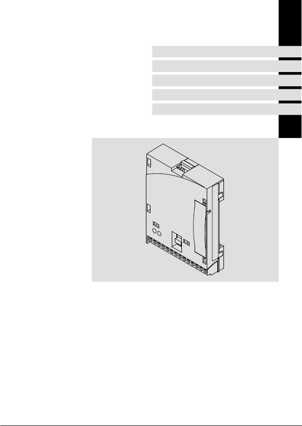
Funktionsmodul
Function module
Module de fonction
Page 2

Lesen Sie zuerst diese Anleitung und die Dokumentation zum Grundgerät,
bevor Sie mit den Arbeiten beginnen!
Beachten Sie die enthaltenen Sicherheitshinweise.
Please read these instructions and the documentation of the standard
device before you start working!
Observe the safety instructions given therein!
Lire le présent fascicule et la documentation relative à l’appareil de base
avant toute manipulation de l’équipement !
Respecter les consignes de sécurité fournies.
Page 3
4
ON
A AB BCNVP
7
40 39 28 20 59
7
+
0
2
3
1
E82ZAFPC001
E82ZAFP004/AFX009
Page 4

Legende zur Abbildung auf der Ausklappseite
Pos. Beschreibung Ausführliche
DIP-Schalter zur Aktivierung des Busabschluss-Widerstandes
Status der PROFIBUS-Kommunikation (gelbe LED)
Verbindungsstatus zum Grundgerät (grüne LED)
Klemmenleiste X3, Anschluss für
PROFIBUS
Reglersperre (CINH)
externe Spannungsversorgung
Typenschild 13
0Abb.0Tab. 0
Information
33
35
26
4
EDK82ZAFPC-001 DE/EN/FR 6.0
Page 5

Inhalt i
1 Über diese Dokumentation 6. . . . . . . . . . . . . . . . . . . . . . . . . . . . . . . . . . . . . . . . . .
Verwendete Konventionen 7. . . . . . . . . . . . . . . . . . . . . . . . . . . . . . . . . . . . . . . . . .
Verwendete Hinweise 8. . . . . . . . . . . . . . . . . . . . . . . . . . . . . . . . . . . . . . . . . . . . . . .
2 Sicherheitshinweise 10. . . . . . . . . . . . . . . . . . . . . . . . . . . . . . . . . . . . . . . . . . . . . . . .
3 Produktbeschreibung 11. . . . . . . . . . . . . . . . . . . . . . . . . . . . . . . . . . . . . . . . . . . . . . .
Funktion 11. . . . . . . . . . . . . . . . . . . . . . . . . . . . . . . . . . . . . . . . . . . . . . . . . . . . . . . . . .
Bestimmungsgemäße Verwendung 11. . . . . . . . . . . . . . . . . . . . . . . . . . . . . . . . . . .
Lieferumfang 12. . . . . . . . . . . . . . . . . . . . . . . . . . . . . . . . . . . . . . . . . . . . . . . . . . . . . .
Identifikation 13. . . . . . . . . . . . . . . . . . . . . . . . . . . . . . . . . . . . . . . . . . . . . . . . . . . . . .
4 Technische Daten 14. . . . . . . . . . . . . . . . . . . . . . . . . . . . . . . . . . . . . . . . . . . . . . . . . .
Allgemeine Daten 14. . . . . . . . . . . . . . . . . . . . . . . . . . . . . . . . . . . . . . . . . . . . . . . . .
Einsatzbedingungen 14. . . . . . . . . . . . . . . . . . . . . . . . . . . . . . . . . . . . . . . . . . . . . . . .
Schutzisolierung 15. . . . . . . . . . . . . . . . . . . . . . . . . . . . . . . . . . . . . . . . . . . . . . . . . . .
Abmessungen 16. . . . . . . . . . . . . . . . . . . . . . . . . . . . . . . . . . . . . . . . . . . . . . . . . . . . .
5 Mechanische Installation 17. . . . . . . . . . . . . . . . . . . . . . . . . . . . . . . . . . . . . . . . . . . .
6 Elektrische Installation 18. . . . . . . . . . . . . . . . . . . . . . . . . . . . . . . . . . . . . . . . . . . . . .
EMV-gerechte Verdrahtung 18. . . . . . . . . . . . . . . . . . . . . . . . . . . . . . . . . . . . . . . . . .
Verdrahtung mit einem Leitrechner 19. . . . . . . . . . . . . . . . . . . . . . . . . . . . . . . . . . .
Busleitungslänge 22. . . . . . . . . . . . . . . . . . . . . . . . . . . . . . . . . . . . . . . . . . . . . . . . . .
Spannungsversorgung 23. . . . . . . . . . . . . . . . . . . . . . . . . . . . . . . . . . . . . . . . . . . . .
Belegung der Anschlussklemmen 26. . . . . . . . . . . . . . . . . . . . . . . . . . . . . . . . . . . . .
Leitungsquerschnitte und Schraubenanzugsmomente 27. . . . . . . . . . . . . . . . . . . .
7 Inbetriebnahme 28. . . . . . . . . . . . . . . . . . . . . . . . . . . . . . . . . . . . . . . . . . . . . . . . . . .
Vor dem ersten Einschalten 28. . . . . . . . . . . . . . . . . . . . . . . . . . . . . . . . . . . . . . . . . .
Inbetriebnahmeschritte 29. . . . . . . . . . . . . . . . . . . . . . . . . . . . . . . . . . . . . . . . . . . . .
Leitsystem konfigurieren 32. . . . . . . . . . . . . . . . . . . . . . . . . . . . . . . . . . . . . . . . . . .
Busabschluss-Widerstand aktivieren 33. . . . . . . . . . . . . . . . . . . . . . . . . . . . . . . . . . .
Netzspannung zuschalten 34. . . . . . . . . . . . . . . . . . . . . . . . . . . . . . . . . . . . . . . . . .
8 Diagnose 35. . . . . . . . . . . . . . . . . . . . . . . . . . . . . . . . . . . . . . . . . . . . . . . . . . . . . . . . .
LED-Statusanzeigen 35. . . . . . . . . . . . . . . . . . . . . . . . . . . . . . . . . . . . . . . . . . . . . . .
EDK82ZAFPC-001 DE/EN/FR 6.0
5
Page 6

1 Über diese Dokumentation
1 Überdiese Dokumentation
Inhalt
Diese Dokumentation enthält ...
ƒ Sicherheitshinweise, die Sie unbedingt beachten müssen;
ƒ Angaben über Versionsstände der zu verwendenden Lenze Grundgeräte;
ƒ Informationen zur mechanischen und elektrischen Installation des Funktionsmoduls;
ƒ Informationen zur Inbetriebnahme des Funktionsmoduls;
ƒ Technische Daten.
Informationen zur Gültigkeit
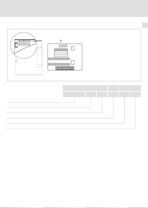
Die Informationen in dieser Dokumentation sind gültig für folgende Geräte:
Funktionsmodul Typenbezeichnung ab Hardwarestand ab Softwarestand
PROFIBUS E82ZAFPC001 3A 10
Zielgruppe
Diese Dokumentation wendetsichanPersonen,die das beschriebene Produkt nach Projektvorgabe installieren und in Betrieb nehmen.
Tipp!
Dokumentationen und Software-Updates zu weiteren Lenze Produkten finden
Sie im Internet im Bereich ”Services & Downloads” unter
http://www.Lenze.com
6
EDK82ZAFPC-001 DE/EN/FR 6.0
Page 7

Über diese Dokumentation
Verwendete Konventionen
Verwendete Konventionen
Diese Dokumentation verwendet folgende Konventionen zur Unterscheidung verschiedener Arten von Information:
Informationsart Auszeichnung Beispiele/Hinweise
Zahlenschreibweise
Dezimaltrennzeichen Punkt Eswird generell der Dezimalpunkt
Symbole
Seitenverweis
verwendet.
Beispiel: 1234.56
Verweis auf eine andere Seite mit zusätzlichen Informationen
Beispiel:16 = siehe Seite 16
1
EDK82ZAFPC-001 DE/EN/FR 6.0
7
Page 8

1 Über diese Dokumentation
Verwendete Hinweise
Verwendete Hinweise
Um auf Gefahren und wichtige Informationen hinzuweisen, werden in dieser Dokumentation folgende Piktogramme und Signalwörter verwendet:
Sicherheitshinweise
Aufbau der Sicherheitshinweise:
Gefahr!
(kennzeichnet die Art und die Schwere der Gefahr)
Hinweistext
(beschreibt die Gefahr und gibt Hinweise, wie sie vermieden werden kann)
Piktogramm und Signalwort Bedeutung
Gefahr von Personenschäden durch gefährliche elektrische Spannung
Gefahr!
Gefahr!
Stop!
Hinweis auf eine unmittelbar drohende Gefahr, die den
Tod oder schwere Verletzungen zur Folge haben kann,
wenn nicht die entsprechenden Maßnahmen getroffen
werden.
Gefahr von Personenschäden durch eine allgemeine Gefahrenquelle
Hinweis auf eine unmittelbar drohende Gefahr, die den
Tod oder schwere Verletzungen zur Folge haben kann,
wenn nicht die entsprechenden Maßnahmen getroffen
werden.
Gefahr von Sachschäden
Hinweis auf eine mögliche Gefahr, die Sachschäden zur
Folge haben kann, wenn nicht die entsprechenden Maßnahmen getroffen werden.
8
EDK82ZAFPC-001 DE/EN/FR 6.0
Page 9

Anwendungshinweise
Piktogramm und Signalwort Bedeutung
Über diese Dokumentation
Verwendete Hinweise
1
Hinweis!
Tipp!
Wichtiger Hinweis für die störungsfreie Funktion
Nützlicher Tipp für die einfache Handhabung
Verweis auf andere Dokumentation
EDK82ZAFPC-001 DE/EN/FR 6.0
9
Page 10

2 Sicherheitshinweise
2 Sicherheitshinweise
Gefahr!
Unsachgemäßer Umgang mit dem Funktionsmodul und dem Grundgerät kann
schwere Personenschäden und Sachschäden verursachen.
Beachten Sie die in der Dokumentation zum Grundgerät enthaltenen
Sicherheitshinweise und Restgefahren.
Stop!
Elektrostatische Entladung
Durch elektrostatische Entladung können elektronische Bauteile innerhalb des
Funkionsmoduls beschädigt oder zerstört werden.
Mögliche Folgen:
ƒ
Das Funktionsmodul ist defekt.
ƒ
Die Feldbus-Kommunikation ist nicht möglich oder fehlerhaft.
Schutzmaßnahmen
ƒ
Befreien Sie sich vor dem Berühren des Moduls von elektrostatischen
Aufladungen.
10
EDK82ZAFPC-001 DE/EN/FR 6.0
Page 11

Produktbeschreibung
Funktion
3 Produktbeschreibung
Funktion
Das Funktionsmodul koppelt Lenze Frequenzumrichter an das serielle Kommunikationssystem PROFIBUS.
Bestimmungsgemäße Verwendung
Das Funktionsmodul ...
ƒ ist eine Zubehör-Baugruppe, die mit folgenden Lenze Grundgeräten eingesetzt
werden kann:
Produktreihe Gerätebezeichnung ab Hardwarestand
Frequenzumrichter
Motorstarter starttec Vx1x
ƒ ist ein Betriebsmittel zum Einsatz in industriellen Starkstromanlagen.
Jede andere Verwendung gilt als sachwidrig!
8200 vector Vx14
8200 motec Vx14
Tipp!
Weiterführende Informationen zu diesem Funktionsmodul finden Sie im
entsprechenden Kommunikationshandbuch.
Die PDF-Datei finden Sie im Internet im Bereich ”Services & Downloads” unter
http://www.Lenze.com
3
EDK82ZAFPC-001 DE/EN/FR 6.0
11
Page 12
3 Produktbeschreibung
Lieferumfang
Lieferumfang
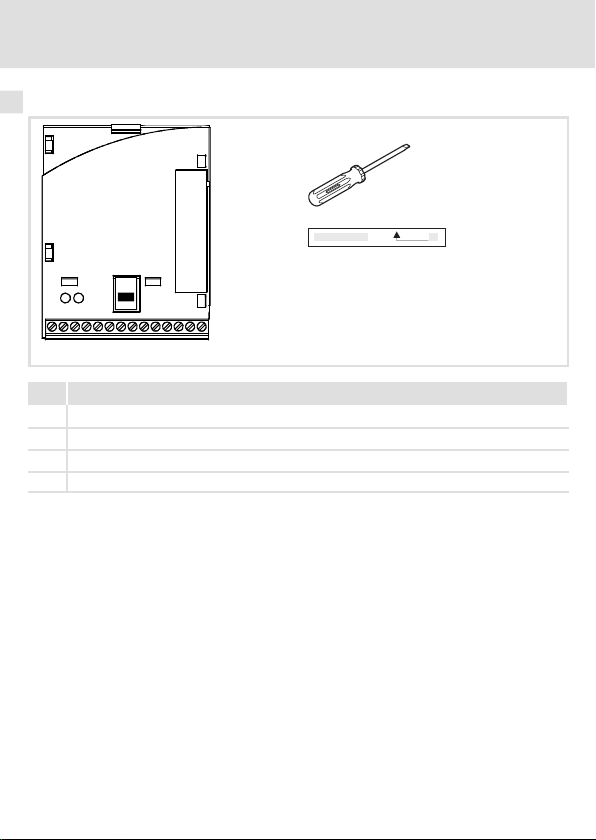
Pos Lieferumfang
Funktionsmodul E82ZAFPC001
Montageanleitung
Schraubendreher
Klebestreifen
E82ZAFP004/E82ZAFL011B
12
EDK82ZAFPC-001 DE/EN/FR 6.0
Page 13
Identifikation
E82AF000P0B201XX
APPLICATION
010/3A22
APPLICATION
010/3A22
L
Type
Id.-No.
Prod.-No.
Ser.-No.
Produktreihe
PROFIBUS
Gerätegeneration
Variante: verlackte Leiterplatten
Hardwarestand
Softwarestand
Produktbeschreibung
Identifikation
E82ZAFX005
E82ZAF P C 001 3A 10
3
EDK82ZAFPC-001 DE/EN/FR 6.0
13
Page 14

4 Technische Daten
Allgemeine Daten
4 Technische Daten
Allgemeine Daten
Bereich Werte
Bestell-Bezeichnung E82ZAFPC001
PNO-Identnummer 0x00DA
Kommunikations-Profil
(DIN 19245 Teil 1 und Teil 3)
Kommunikationsmedium RS485
Antriebs-Profil DRIVECOM-Profil ”Antriebstechnik 20”, abschaltbar
Netzwerk-Topologie
PROFIBUS-Teilnehmer Slave
Übertragungsrate [kBit/s] 9.6 ... 12000 (automatische Erkennung)
Prozessdatenworte 1 ... 10 Worte
DP-Nutzdatenlänge 4 Parameterdatenworte +
Max. Anzahl Teilnehmer
Max. Leitungslänge pro BusSegment
Externe DC-Spannungsversorgung
Einsatzbedingungen
Umgebungsbedingungen
Klimatisch
Lagerung IEC/EN60721-3-1 1K3 (-25 ... +60 °C)
Transport IEC/EN 60721-3-2 2K3 (-25 ... +70 °C)
Betrieb Entsprechend der Daten des verwendeten Lenze Grundgerätes (siehe
Verschmutzung EN 61800-5-1 Verschmutzungsgrad 2
Schutzart IP20 (Berührschutz nach NEMA 250 Typ 1)
Dokumentation des Grundgerätes).
hex
PROFIBUS-DP-V0
ohne Repeater: Linie
mit Repeater: Linie oder Baum
(16 Bit je Wort)
1 ... 10 Prozessdatenworte
Standard: 32 (= 1 Bus-Segment)
mit Repeater: 125
1200 m (abhängig von Übertragungsrate und verwendetem Kabeltyp)
+24 V DC ±10 %, max. 80 mA
14
EDK82ZAFPC-001 DE/EN/FR 6.0
Page 15

Technische Daten
Schutzisolierung
Schutzisolierung
Schutzisolierung zwischen Bus und ... Art der Isolierung (nach EN 61800-5-1)
Leistungsteil
– 8200 vector Verstärkte Isolierung
– 8200 motec Verstärkte Isolierung
– starttec Verstärkte Isolierung
Bezugserde / PE (X3/7) Betriebsisolierung
externer Versorgung (X3/59) Betriebsisolierung
Klemme X3/20 Betriebsisolierung
Klemme X3/28 Betriebsisolierung
4
EDK82ZAFPC-001 DE/EN/FR 6.0
15
Page 16
4 Technische Daten
Abmessungen
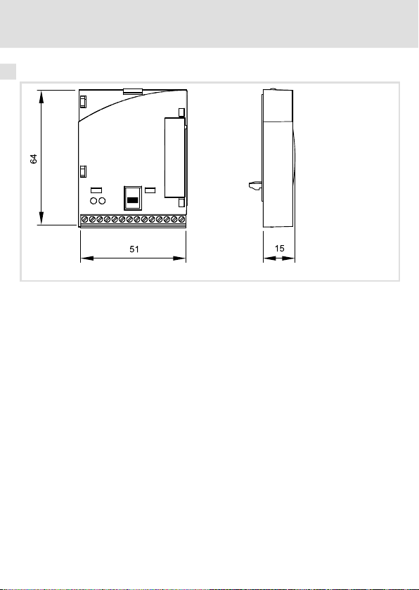
Abmessungen
alle Maße in mm
E82ZAFL011B
16
EDK82ZAFPC-001 DE/EN/FR 6.0
Page 17

Mechanische Installation 5
5 MechanischeI nstallation
Folgen Sie zur mechanischen Installation des Funktionsmoduls den Hinweisen in der Montageanleitung des Grundgerätes.
Die Montageanleitung des Grundgerätes ...
ƒ ist Teil des Lieferumfangs und liegt jedem Gerät bei.
ƒ gibt Hinweise, um Beschädigungen durch unsachgemäße Behandlung zu vermeiden.
ƒ beschreibt die einzuhaltende Reihenfolge der Installationsschritte.
EDK82ZAFPC-001 DE/EN/FR 6.0
17
Page 18

6 Elektrische Installation
EMV-gerechte Verdrahtung
6 ElektrischeInstal lation
EMV-gerechte Verdrahtung
Für eine EMV-gerechte Verdrahtung beachten Sie folgende Punkte:
Hinweis!
ƒ
Steuer-/Datenleitungen getrennt von Motorleitungen verlegen.
ƒ
Legen Sie die Schirme der Steuer-/Datenleitungen bei digitalen Signalen
beidseitig
ƒ
ƒ
Vorgehensweise bei der Verdrahtung
1. Bustopologie einhalten, deshalb keine Stichleitungen verwenden.
2. Hinweise und Verdrahtungsvorschriften in den Unterlagen zum Steuerungssystem
beachten.
3. Nur Kabel verwenden, die den aufgeführten Spezifikationen entsprechen (21).
4. Hinweise zur Spannungsversorgung des Moduls beachten (23).
5. Busabschluss-Widerstände am physikalisch ersten und letzten Teilnehmer aktivieren
(33).
auf.
Zur Vermeidung von Potenzialdifferenzen zwischen den
Kommunikationsteilnehmern eine Ausgleichsleitung mit einem
Querschnitt von mindestens 16 mm2einsetzen (Bezug: PE).
Beachten Sie die weiteren Hinweise zur EMV-gerechten Verdrahtung in der
Dokumentation des Grundgerätes.
18
EDK82ZAFPC-001 DE/EN/FR 6.0
Page 19

Elektrische Installation
Verdrahtung mit einem Leitrechner
Verdrahtung mit einem Leitrechner
Gefahr!
Gefährliche elektrische Spannung
Bei Einsatz von Lenze-Antriebsreglern an einem außenleitergeerdeten Netz mit
einer Netz-Nennspannung≥400 V ist die Berührsicherheit ohne externe
Maßnahmen nicht sichergestellt.
Mögliche Folgen:
ƒ
Tod oder schwere Verletzungen
Schutzmaßnahmen:
ƒ
Ist Berührsicherheit für die Steuerklemmen des Antriebsreglers und für die
Anschlüsse der gesteckten Gerätemodule gefordert, ...
– muss eine doppelte Trennstrecke vorhanden sein.
– müssen die anzuschliesenden Komponenten die zweite Trennstrecke
aufweisen.
6
EDK82ZAFPC-001 DE/EN/FR 6.0
19
Page 20
6 Elektrische Installation
starttec
8200vector
8200motec
+
E82ZAFPC0xx
starttec
8200vector
8200motec
+
E82ZAFPC0xx
starttec
8200vector
8200motec
+
E82ZAFPC0xx
3 3 3
1
2 2 2
0m
1200m
Verdrahtung mit einem Leitrechner
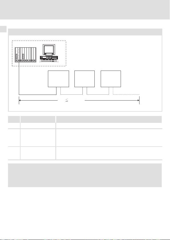
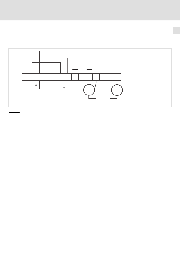
Prinzipieller Aufbau eines PROFIBUS-Netzwerks mit RS485-Verkabelung ohne Repeater
E82ZAFP005
Nr. Element Bemerkung
1 Leitrechner z. B. PC oder SPS mit PROFIBUS Master-Anschaltbaugruppe
2 Buskabel Verbindet die PROFIBUS Master-Anschaltbaugruppe mit den Funkti-
3 PROFIBUS-Slave Einsetzbares Grundgerät (11) mit Funktionsmodul
onsmodulen.
Die Übertragungsrate ist abhängig von der Länge des Buskabels
(22).
Busabschluss-Widerstände am physikalisch ersten und letzten
Teilnehmer aktivieren (33).
Hinweis!
Bei Einsatz eines Repeaters können max. 125 Teilnehmer über den PROFIBUS
miteinander kommunizieren.
20
EDK82ZAFPC-001 DE/EN/FR 6.0
Page 21

Elektrische Installation
Verdrahtung mit einem Leitrechner
Spezifikation des Übertragungskabels
Hinweis!
Verwenden Sie ausschließlichKabel, die den aufgeführten Spezifikationen der
PROFIBUS-Nutzerorganisation entsprechen.
Bereich Werte
Leitungswiderstand
Kapazitätsbelag
Schleifenwiderstand
Aderdurchmesser > 0.64 mm
Aderquerschnitt > 0.34 mm
Adern 2-fach verdrillt, isoliert und abgeschirmt
135 ... 165Ω/km, (f = 3 ... 20 MHz)
≤
30 nF/km
< 110Ω/km
2
6
EDK82ZAFPC-001 DE/EN/FR 6.0
21
Page 22

6 Elektrische Installation
Busleitungslänge
Busleitungslänge
Die Länge des Buskabels ist abhängig von der verwendeten Übertragungsrate:
Übertragungsrate [kBit/s] Länge [m]
9.6 ... 93.75 1200
187.5 1000
500 400
1500 200
3000 ... 12000 100
Hinweis!
Die von Datenmenge, Zykluszeit und Teilnehmeranzahl abhängige
Übertragungsrate sollte nur so hoch gewählt werden, wie es für die
Anwendung erforderlich ist.
Tipp!
Bei hohen Übertragungsraten empfehlen wir den Einsatz von
Lichtwellenleitern zu prüfen.
Vorteile des Lichtwellenleiters:
ƒ
Auf dem Übertragungsweg bleiben externe elektromagnetische Störungen
unwirksam.
ƒ
Buslängen von mehreren Kilometern sind auch bei höheren
Übertragungsraten möglich. Die Buslänge ist
– unabhängig von der Übertragungsrate.
– abhängig vom verwendeten Lichtwellenleiter.
22
EDK82ZAFPC-001 DE/EN/FR 6.0
Page 23
Elektrische Installation
GND1
GND1
B
CN
7
20 59
X3
+5V
+20V
A VP
2839
7
BA
T/R(A) T/R(B) T/R(A) T/R(B)
GND2
40
GND3
+
Spannungsversorgung
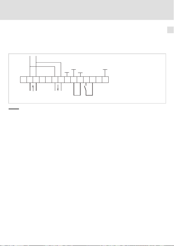
Spannungsversorgung
Interne DC-Spannungsversorgung
Die interne Spannung steht an der Klemme X3/20 zur Verfügung. Sie dient zur Versorgung
der Reglersperre (CINH).
E82ZAFP001
Für den Betrieb notwendige Mindestverdrahtung
6
EDK82ZAFPC-001 DE/EN/FR 6.0
23
Page 24
6 Elektrische Installation
GND1
GND1
B
CN
7
20 59
X3
+5V
+20V
A VP
2839
7
BA
T/R(A) T/R(B) T/R(A) T/R(B)
GND2
_
+
40
GND3
+
Spannungsversorgung
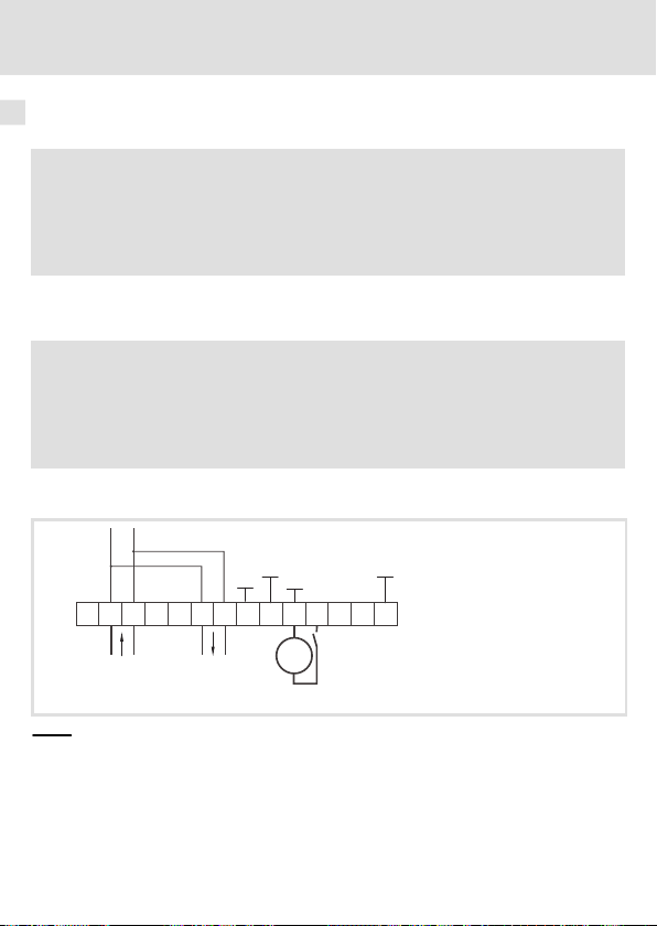
Externe Spannungsversorgung
Hinweis!
Verwenden Sie bei externer Spannungsversorgung und bei größeren
Entfernungen zwischen den Schaltschränken in jedem Schaltschrank immer
ein separates und nach EN 61800-5-1 sicher getrenntes Netzteil
(”SELV”/”PELV”).
Die externe Spannungversorgung der Kommunikationsbaugruppe ist dann notwendig,
wenn beim Ausfall der Versorgung des Grundgerätes die Kommunikation über den Feldbus
bestehen bleiben soll.
Hinweis!
Bei externer Spannungsversorgung des Funktionsmoduls wird der aktive
Busabschluss-Widerstand unabhängig vom Betrieb des Grundgerätes gespeist.
Das Bussystem bleibt dadurch auch dann weiter aktiv, wenn das Grundgerät
abgeschaltet wird oder ausfallen sollte.
Externe Spannungsversorgung mit
ƒ X3/28 (Reglersperre (CINH))
einer
Spannungsquelle von
Für den Betrieb notwendige Mindestverdrahtung
24
E82ZAFP002
EDK82ZAFPC-001 DE/EN/FR 6.0
Page 25
Elektrische Installation
GND1
GND1
B
CN
720
59
X3
+5V
+20V
A
+
VP
28397
BA
T/R(A) T/R(B) T/R(A) T/R(B)
GND2
_
_
+
+
40
GND3
Spannungsversorgung
6
Externe Spannungsversorgung mit
1. X3/28 (Reglersperre (CINH))
2. X3/59 (Funktionsmodul)
Für den Betrieb notwendige Mindestverdrahtung
zwei
Spannungsquellen von
E82ZAFP003
EDK82ZAFPC-001 DE/EN/FR 6.0
25
Page 26

6 Elektrische Installation
Belegung der Anschlussklemmen
Belegung der Anschlussklemmen
Klemme
X3/
A T/R(A) RS485 Datenleitung A
B T/R(B) RS485 Datenleitung B
CN CNTR Funktion siehe PROFIBUS-Norm *)
VP Funktion siehe PROFIBUS-Norm *)
40 GND3 Bezugspotenzial für PROFIBUS-Netzwerk *)
7 GND1 Bezugspotenzial für X3/20
39 GND2 Bezugspotenzial der Reglersperre (CINH) an X3/28
28 CINH Reglersperre
20 DC-Spannungsquelle zur internen Versorgung der Reglersperre
59 Externe DC-Spannungsversorgung des Funktionsmoduls
*) z. B. bei Anschluss eines Repeaters
Bezeichnung Funktion / Pegel
PES Zusätzlicher HF-Schirmabschluss
Pegel beim Senden von Daten: CNTR = HIGH
(+5 V DC, Bezug: GND3)
U = +5 V DC (Bezug: GND3)
I
= 10 mA
max
Start = HIGH (+12 ... +30 V DC)
Stop = LOW (0 ... +3 V DC)
(Bezug: GND2)
(CINH)
+20 V DC (Bezug: GND1)
I
= 20 mA
max
+24 V DC±10% (Bezug: GND1)
Stromaufnahme an 24 V DC: 80 mA
Beim Durchschleifen der Versorgungsspannung zu anderen
Busteilnehmern über die Klemme 59 darf der fließende Strom max.
3 A betragen.
26
EDK82ZAFPC-001 DE/EN/FR 6.0
Page 27
Leitungsquerschnitte und Schraubenanzugsmomente
Elektrische Installation
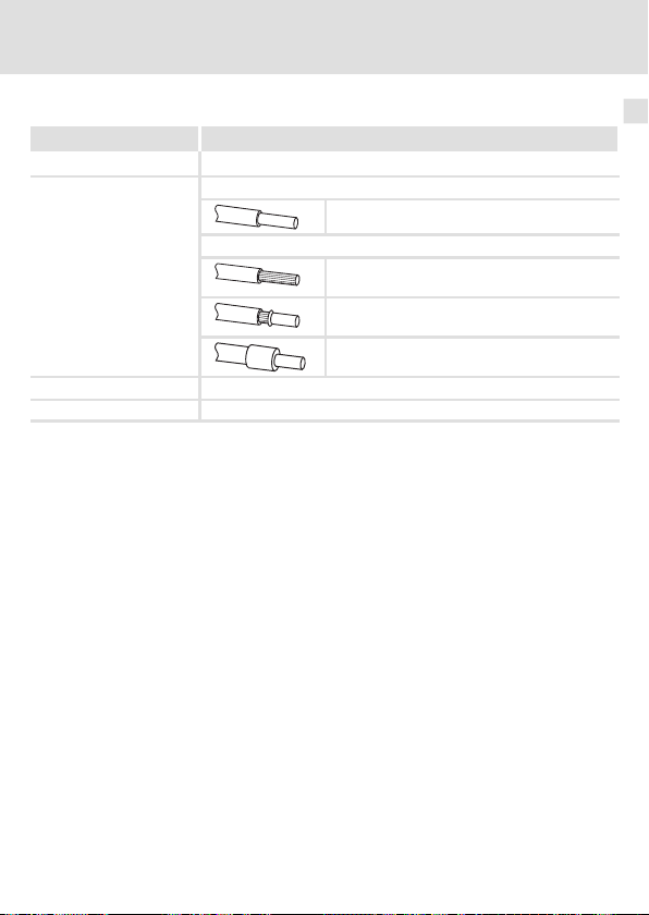
Leitungsquerschnitte und Schraubenanzugsmomente
Bereich Werte
Elektrischer Anschluss Klemmenleiste mit Schraubanschluss
Anschlussmöglichkeiten
Anzugsmoment 0.22 ... 0.25 Nm (1.9 ... 2.2 lb-in)
Abisolierlänge 5 mm
starr:
flexibel:
1.5 mm2(AWG 16)
ohne Aderendhülse
1.0 mm2(AWG 18)
mit Aderendhülse, ohne Kunststoffhülse
0.5 mm2(AWG 20)
mit Aderendhülse, mit Kunststoffhülse
0.5 mm2(AWG 20)
6
EDK82ZAFPC-001 DE/EN/FR 6.0
27
Page 28

7 Inbetriebnahme
Vor dem ersten Einschalten
7 Inbetriebnahme
Vor dem ersten Einschalten
Stop!
Bevor Sie das Grundgerät mit dem Funktionsmodul erstmalig einschalten,
überprüfen Sie ...
ƒ
die gesamte Verdrahtung auf Vollständigkeit, Kurzschluss und Erdschluss.
ƒ
ob beim physikalisch ersten und letzten Busteilnehmer der integrierte
Busabschluss-Widerstand aktiviert ist(33).
28
EDK82ZAFPC-001 DE/EN/FR 6.0
Page 29

Inbetriebnahme
Inbetriebnahmeschritte
Inbetriebnahmeschritte
Hinweis!
Halten Sie unbedingt die Einstellreihenfolge ein.
Die schrittweise Inbetriebnahme des Funktionsmoduls mit der DRIVECOM-Gerätesteuerung ist nachfolgend beschrieben.
Schritt Beschreibung Ausführliche
1. Leitsystem (Master) für die Kommunikation mit dem Funktionsmodul
2. Grundgerät über Klemme 28 (CINH) sperren.
3.
4. Busabschluss-Widerstand beim ersten und letzten Busteilnehmer mit
konfigurieren.
Klemme 28 auf LOW-Pegel legen.
Das Grundgerät kann später über den Bus gesperrt und freigegeben werden.
Netzspannung zuschalten und, wenn vorhanden, separate Spannungsversorgung des Funktionsmoduls zuschalten.
Das Grundgerät ist nach ca. 1 Sekunde betriebsbereit.
Die Reglersperre (CINH) ist aktiv.
Reaktion
Die grüne LED ”Verbindungsstatus zum Grundgerät” auf der
Frontseite des Funktionsmoduls leuchtet (nur sichtbar beim 8200
vector).
Keypad:
(falls aufgesteckt)
DIP-Schalter = ON aktivieren.
Lenze-Einstellung: OFF
Information
32
Dokumentation
des Grundgerätes
34
35
33
7
EDK82ZAFPC-001 DE/EN/FR 6.0
29
Page 30

7 Inbetriebnahme
Inbetriebnahmeschritte
BeschreibungSchritt
5. A Teilnehmeradresse einstellen über ...
6.
7. Funktionsmodul als Quelle für Steuerbefehle und Sollwerte wählen.
8.
– C1509
Nach einem Parametersatz-Transfer muss die Adresse erneut zugewiesen werden.
B Schalten Sie die Spannungsversorgung des Funktionsmoduls und
des Grundgerätes aus- und wieder ein, um geänderte Einstellungen zu übernehmen.
Die Änderung der Adresse über Keypad wird sofort wirksam.
Sie können jetzt mit dem Grundgerät kommunizieren, d. h. alle Codestellen lesen und alle beschreibbaren Codestellen an Ihre Anwendung
anpassen.
Reaktion
Die gelbe LED auf dem Funktionsmodul blinkt, wenn der PROFIBUS
aktiv ist.
C0005 = 200 einstellen.
– Eine Vorkonfiguration für den Betrieb mit dem Funktions-
modul wird durchgeführt.
– Steuerworte und Statusworte sind dabei bereits verknüpft.
Prozessdaten-Ausgangsworte (PAW) des Masters über C1511 den
Prozessdaten-Eingangsworten des Grundgerätes zuordnen.
Lenze-Einstellung:
PAW1: DRIVECOM-Steuerwort (DRIVECOM CTRL)
PAW2: Sollwert1 (NSET1-N1)
PAW3: Sollwert2 (NSET1-N2)
PAW4: Zusatzsollwert (PCTRL1-NADD)
PAW5: Prozessregler-Istwert (PCTRL1-ACT)
PAW6: Prozessregler-Sollwert (PCTRL1-SET1)
PAW7: reserviert (FIF-RESERVED)
PAW8: Drehmoment-Sollwert oder Drehmoment-Grenzwert
(MCTRL1-MSET)
PAW9: PWM-Spannung (MCTRL1-VOLT-ADD)
PAW10: PWM-Winkel (MCTRL1-PHI-ADD)
Ausführliche
Information
Dokumentation
des Grundgerätes
Dokumentation
des Grundgerätes
35
Kommunikationshandbuch
PROFIBUS
30
EDK82ZAFPC-001 DE/EN/FR 6.0
Page 31

Inbetriebnahme
Inbetriebnahmeschritte
7
BeschreibungSchritt
9.
10. Prozess-Ausgangsdaten mit C1512 = 65535 freigeben.
11. Grundgerät über Klemme 28 (CINH) freigeben.
12. Sollwert vorgeben.
13. In den Zustand EINSCHALTBEREIT wechseln:
14. Das Grundgerät ist im Zustand EINSCHALTBEREIT.
15. In den Zustand BETRIEB-FREIGEGEBEN wechseln.
16. Der Antrieb läuft jetzt an.
Prozessdaten-Ausgangsworte des Grundgerätes über C1510 den
Prozessdaten-Eingangsworten (PEW) des Masters zuordnen.
Lenze-Einstellung:
PEW1: DRIVECOM-Statuswort (DRIVECOM STAT)
PEW2: Ausgangsfrequenz mit Schlupf (MCTRL1-NOUT+SLIP)
PEW3: Ausgangsfrequenz ohne Schlupf (MCTRL1-NOUT)
PEW4: Motor-Scheinstrom (MCTRL1-IMOT)
PEW5: Prozessregler-Istwert (PCTRL1-ACT)
PEW6: Prozessregler-Sollwert (PCTRL1-SET1)
PEW7: Prozessregler-Ausgang (PCTRL1-OUT)
PEW8: Geräteauslastung (MCTRL1-MOUT)
PEW9: Zwischenkreisspannung (MCTRL1-DCVOLT)
PEW10: Hochlaufgeber-Eingang (NSET1-RFG1-IN)
Nur notwendig wenn C1511 verändert wurde.
Deaktivieren Sie nicht verwendete Prozessdatenworte durch
Setzen des jeweiligen Subcodes der Codestelle C1511 = 0.
Der Wert in C1512 ist flüchtig und nach jedem Einschalten sind
alle Prozessdaten freigegeben.
Klemme 28 auf HIGH-Pegel legen.
Der Master sendet den Sollwert über das gewählte ProzessdatenAusgangswort.
Der Master sendet das DRIVECOM-Steuerwort:
0000 0000 0111 1110
Der Master empfängt das DRIVECOM-Statuswort:
xxxx xxxx x01x 0001
Der Master sendet DRIVECOM-Steuerwort:
0000 0000 0111 1111
bin.
(007E
(007F
hex
hex
).
).
bin
bin
Ausführliche
Information
Kommunikationshandbuch
PROFIBUS
Kommunikationshandbuch
PROFIBUS
EDK82ZAFPC-001 DE/EN/FR 6.0
31
Page 32

7 Inbetriebnahme
Leitsystem konfigurieren
Leitsystem konfigurieren
Zur Kommunikation mit der Kommunikationsbaugruppe muss zunächst das Leitsystem
konfiguriert werden.
Einstellungen am Master
Zur Projektierung des PROFIBUS muss in der Projektierungssoftware des Masters die Gerätestammdatendatei (GSD-Datei) der Kommunikationsbaugruppeeingelesen werden.
Tipp!
Die GSD-Datei kann im Bereich ”Services & Downloads” unter www.Lenze.com
heruntergeladen werden.
32
EDK82ZAFPC-001 DE/EN/FR 6.0
Page 33

Busabschluss-Widerstand aktivieren
ON
Busabschluss-Widerstand aktivieren
DIP-Schalter
Schalterstellung Funktion
OFF Busabschluss-Widerstand nicht aktiv.
ON Busabschluss-Widerstand aktiv.
Inbetriebnahme
E82ZAFL011B / E82ZAFP010
7
EDK82ZAFPC-001 DE/EN/FR 6.0
33
Page 34

7 Inbetriebnahme
Netzspannung zuschalten
Netzspannung zuschalten
Hinweis!
Wenn Sie die externe Spannungsversorgung des Funktionsmoduls benutzen,
schalten Sie diese ebenfalls ein.
ƒ Nach dem Einschalten der Versorgungsspannung ist das Grundgerät nach ca. 1 s
betriebsbereit.
ƒ Die Reglersperre ist aktiv.
ƒ Die grüne LED auf der Frontseite des Funktionsmoduls leuchtet (nur sichtbar beim
Frequenzumrichter 8200 vector).
Schutz vor unkontrolliertem Wiederanlauf
Hinweis!
Aufbau der Kommunikation
Zum Aufbau der Kommunikation ist es beim extern versorgten
Funktionsmodul erforderlich, auch das Grundgerät anfangs einzuschalten.
ƒ
Die weitere Kommunikation des extern versorgten Moduls bleibt
anschließend unabhängig vom Einschaltzustand des Grundgerätes.
Schutz vor unkontrolliertem Wiederanlauf
Nach einer Störung (z. B. kurzzeitiger Netzausfall) ist der Wiederanlauf eines
Antriebs in manchen Fällen unerwünscht oder sogar unzulässig.
In C0142 lässt sich das Wiederanlaufverhalten des Antriebsreglers einstellen:
ƒ
C0142 = 0 (Lenze-Einstellung)
– Der Antriebsregler bleibt gesperrt (auch wenn die Störung nicht mehr
aktiv ist).
– Der Antrieb läuft kontrolliert an durch explizite Reglerfreigabe:
LOW-HIGH-Flanke an Klemme 28 (CINH)
ƒ
C0142 = 1
– Ein unkontrollierter Anlauf des Antriebs ist möglich.
34
EDK82ZAFPC-001 DE/EN/FR 6.0
Page 35

8 Diagnose
LED-Statusanzeigen
LED
Pos. Farbe Zustand
gelb
+
aus Keine Kommunikation mit dem PROFIBUS-Master vorhanden.
blinkt Die Kommunikation über das Funktionsmodul zum
grün
aus
blinkt Das Funktionsmodul ist mit Spannung versorgt, hat aber keine
an Das Funktionsmodul ist mit Spannung versorgt und hat eine Ver-
gelb /
blinkt Interner Fehler des Funktionsmoduls
grün
Diagnose
LED-Statusanzeigen
Beschreibung
PROFIBUS-Master ist aufgebaut.
Das Funktionsmodul wird nichtmitSpannungversorgt.
Das Grundgerät und/oder die externe Spannungsversorgung
ist ausgeschaltet.
Verbindung zum Grundgerät.
Ursachen:
Das Grundgerät ist abgeschaltet.
Das Grundgerät ist in derInitialisierungsphase.
Das Grundgerät ist nicht vorhanden.
bindung zum Grundgerät.
8
E82ZAFP008
EDK82ZAFPC-001 DE/EN/FR 6.0
35
Page 36

Legend for fold-out page
Pos. Description Detailed
DIP switch for activating the bus terminating resistor
Status of PROFIBUS communication (yellow LED)
Connection status to the standard device (green LED)
Terminal strip X3, connection for
PROFIBUS
Controller inhibit (CINH)
External voltage supply
Nameplate
0Fig.0Tab. 0
information
65
67
58
45
36
EDK82ZAFPC-001 DE/EN/FR 6.0
Page 37

Contents i
1 About this documentation 38. . . . . . . . . . . . . . . . . . . . . . . . . . . . . . . . . . . . . . . . . . .
Conventions used 39. . . . . . . . . . . . . . . . . . . . . . . . . . . . . . . . . . . . . . . . . . . . . . . . . .
Notes used 40. . . . . . . . . . . . . . . . . . . . . . . . . . . . . . . . . . . . . . . . . . . . . . . . . . . . . . . .
2 Safety instructions 42. . . . . . . . . . . . . . . . . . . . . . . . . . . . . . . . . . . . . . . . . . . . . . . . .
3 Product description 43. . . . . . . . . . . . . . . . . . . . . . . . . . . . . . . . . . . . . . . . . . . . . . . . .
Function 43. . . . . . . . . . . . . . . . . . . . . . . . . . . . . . . . . . . . . . . . . . . . . . . . . . . . . . . . .
Application as directed 43. . . . . . . . . . . . . . . . . . . . . . . . . . . . . . . . . . . . . . . . . . . . . .
Scope of supply 44. . . . . . . . . . . . . . . . . . . . . . . . . . . . . . . . . . . . . . . . . . . . . . . . . . . .
Identification 45. . . . . . . . . . . . . . . . . . . . . . . . . . . . . . . . . . . . . . . . . . . . . . . . . . . . . .
4 Technical data 46. . . . . . . . . . . . . . . . . . . . . . . . . . . . . . . . . . . . . . . . . . . . . . . . . . . . .
General Data 46. . . . . . . . . . . . . . . . . . . . . . . . . . . . . . . . . . . . . . . . . . . . . . . . . . . . . .
Operating conditions 46. . . . . . . . . . . . . . . . . . . . . . . . . . . . . . . . . . . . . . . . . . . . . . .
Protective insulation 47. . . . . . . . . . . . . . . . . . . . . . . . . . . . . . . . . . . . . . . . . . . . . . . .
Dimensions 48. . . . . . . . . . . . . . . . . . . . . . . . . . . . . . . . . . . . . . . . . . . . . . . . . . . . . . .
5 Mechanical installation 49. . . . . . . . . . . . . . . . . . . . . . . . . . . . . . . . . . . . . . . . . . . . .
6 Electrical installation 50. . . . . . . . . . . . . . . . . . . . . . . . . . . . . . . . . . . . . . . . . . . . . . .
Wiring according to EMC 50. . . . . . . . . . . . . . . . . . . . . . . . . . . . . . . . . . . . . . . . . . . .
Wiring to a host 51. . . . . . . . . . . . . . . . . . . . . . . . . . . . . . . . . . . . . . . . . . . . . . . . . . . .
Bus cable length 54. . . . . . . . . . . . . . . . . . . . . . . . . . . . . . . . . . . . . . . . . . . . . . . . . . .
Voltage supply 55. . . . . . . . . . . . . . . . . . . . . . . . . . . . . . . . . . . . . . . . . . . . . . . . . . . .
Assignment of the terminals 58. . . . . . . . . . . . . . . . . . . . . . . . . . . . . . . . . . . . . . . . .
Cable cross-sections and screw-tightening torques 59. . . . . . . . . . . . . . . . . . . . . . .
7 Commissioning 60. . . . . . . . . . . . . . . . . . . . . . . . . . . . . . . . . . . . . . . . . . . . . . . . . . . .
Before switching on 60. . . . . . . . . . . . . . . . . . . . . . . . . . . . . . . . . . . . . . . . . . . . . . . .
Commissioning steps 61. . . . . . . . . . . . . . . . . . . . . . . . . . . . . . . . . . . . . . . . . . . . . . .
Configuring the host system 64. . . . . . . . . . . . . . . . . . . . . . . . . . . . . . . . . . . . . . . .
Activating the bus terminating resistor 65. . . . . . . . . . . . . . . . . . . . . . . . . . . . . . . .
Connecting the mains voltage 66. . . . . . . . . . . . . . . . . . . . . . . . . . . . . . . . . . . . . . . .
8 Diagnostics 67. . . . . . . . . . . . . . . . . . . . . . . . . . . . . . . . . . . . . . . . . . . . . . . . . . . . . . .
LED status displays 67. . . . . . . . . . . . . . . . . . . . . . . . . . . . . . . . . . . . . . . . . . . . . . . .
EDK82ZAFPC-001 DE/EN/FR 6.0
37
Page 38

1 About this documentation
1 Aboutthis documentation
Contents
This documentation includes ...
ƒ Safety instructions which you must observe in any case;
ƒ Data about the versions of Lenze basic devices to be used;
ƒ Information about the mechanical and electrical installation of the function module;
ƒ Information about the commissioning of the function module;
ƒ Technical data.
Validity information
The information given in this documentation is valid for the following devices:
Function module Type designation From hardware version From software version
PROFIBUS E82ZAFPC001 3A 10
Target group
This documentation is intended for persons who install and commission the described
product according to the project requirements.
Tip!
Documentation and software updates for further Lenze products can be found
on the Internet in the ”Services & Downloads” area under
http://www.Lenze.com
38
EDK82ZAFPC-001 DE/EN/FR 6.0
Page 39

About this documentation
Conventions used
Conventions used
This documentation uses the following conventions to distinguish between differenttypes
of information:
Type of information Identification Examples/notes
Numbers
Decimal separator Point The decimal point is used throughout
Symbols
Page reference
this documentation.
Example: 1234.56
Reference to another page with
additional information
Example:16 = see page 16
1
EDK82ZAFPC-001 DE/EN/FR 6.0
39
Page 40

1 About this documentation
Notes used
Notes used
The following pictographs and signal words are used in this documentation to indicate
dangers and important information:
Safety instructions
Structure of safety instructions:
Danger!
(characterises the type and severity of danger)
Note
(describes the danger and gives information about how to prevent dangerous
situations)
Pictograph and signal word Meaning
Danger of personal injury through dangerous electrical
voltage.
Danger!
Danger!
Stop!
Reference to an imminent danger that may result in
death or serious personal injury if the corresponding
measures are not taken.
Danger of personal injury through a general source of
danger.
Reference to an imminent danger that may result in
death or serious personal injury if the corresponding
measures are not taken.
Danger of property damage.
Reference to a possible danger that may result in
property damage if the corresponding measures are not
taken.
40
EDK82ZAFPC-001 DE/EN/FR 6.0
Page 41

Application notes
Pictograph and signal word Meaning
About this documentation
Notes used
1
Note!
Tip!
Important note to ensure troublefree operation
Useful tip for simple handling
Reference to another documentation
EDK82ZAFPC-001 DE/EN/FR 6.0
41
Page 42

2 Safety instructions
2 Safetyin structions
Danger!
Inappropriate handling of the function module and the standard device can
cause serious injuries to persons and damage to material assets.
Observe the safety instructions and residual hazards included in the
documentation of the standard device.
Stop!
Electrostatic discharge
Electronic components within the function module can be damaged or
destroyed by electrostatic discharge.
Possible consequences:
ƒ
The function module is defective.
ƒ
Fieldbus communication is not possible or faulty.
Protective measures
ƒ
Free yourself from any electrostatic charge before you touch the module.
42
EDK82ZAFPC-001 DE/EN/FR 6.0
Page 43

Product description
Function
3 Productdescription
Function
The function module connects Lenze frequency inverters to the serial PROFIBUS
communication system.
Application as directed
The function module ...
ƒ is an accessory module for use in conjunction with the following Lenze standard
devices:
Product range Device identification From hardware version
Frequency inverter
Motor starter starttec Vx1x
ƒ is a device intended for use in industrial power systems.
Any other use shall be deemed inappropriate!
Tip!
More information about this function module is available in the corresponding
communication manual.
The PDF file can be downloaded from the Internet in the ”Services &
Downloads” area at
http://www.Lenze.com
8200 vector Vx14
8200 motec Vx14
3
EDK82ZAFPC-001 DE/EN/FR 6.0
43
Page 44

3 Product description
Scope of supply
Scope of supply
Pos Scope of supply
E82ZAFPC001function module
Mounting Instructions
Screw driver
Adhesive tape
E82ZAFP004/E 82ZAFL011B
44
EDK82ZAFPC-001 DE/EN/FR 6.0
Page 45

Identification
E82AF000P0B201XX
APPLICATION
010/3A22
APPLICATION
010/3A22
L
Type
Id.-No.
Prod.-No.
Ser.-No.
Product series
PROFIBUS
Version
Variant: coated printed circuit boards
Hardware version
Software version
Product description
Identification
E82ZAFX005
E82ZAF P C 001 3A 10
3
EDK82ZAFPC-001 DE/EN/FR 6.0
45
Page 46

4 Technical data
General Data
4 Technical data
General Data
Field Values
Order designation E82ZAFPC001
PUO ID number 0x00DA
Communication profile
(DIN 19245 part 1 and part 3)
Communication medium RS485
Drive profile ”Drive technology 20” DRIVECOM profile, can be switched off
Network topology
PROFIBUS nodes Slave
Baud rate [kbps] 9.6 ... 12000 (automatic recognition)
Process data words 1 ... 10 words
DP user data length 4 parameter data words +
Max. number of nodes
Max. cable length per bus
segment
External DC voltage supply +24 V DC ±10 %, max. 80 mA
Operating conditions
Ambient conditions
Climate
Storage IEC/EN 60721-3-1 1K3 (-25 to +60 °C)
Transport IEC/EN 60721-3-2 2K3 (-25 to +70 °C)
Operation Corresponding to the data of the Lenze standard device used (see
Pollution EN 61800-5-1 Degree of pollution 2
Degree of protection IP20 (protection against accidental contact according to NEMA 250 type 1)
documentation of the standard device).
hex
PROFIBUS-DP-V0
Without repeater: line
With repeater: line or tree
(16 bits per word)
1 ... 10 process data words
Standard: 32 (= 1 bus segment)
With repeater: 125
1200 m (depending on the baud rate and cable type used)
46
EDK82ZAFPC-001 DE/EN/FR 6.0
Page 47

Technical data
Protective insulation
Protective insulation
Protective insulation between bus and ... Type of insulation (according to EN 61800-5-1)
Power section
– 8200 vector Reinforced insulation
– 8200 motec Reinforced insulation
– starttec Reinforced insulation
Reference earth / PE (X3/7) Functional insulation
External supply (X3/59) Functional insulation
Terminal X3/20 Functional insulation
Terminal X3/28 Functional insulation
4
EDK82ZAFPC-001 DE/EN/FR 6.0
47
Page 48

4 Technical data
Dimensions
Dimensions
All dimensions in mm
E82ZAFL011B
48
EDK82ZAFPC-001 DE/EN/FR 6.0
Page 49

Mechanical installation 5
5 Mechanical installation
Follow the notes given in the Mounting Instructions for the standard device for the
mechanical installation of the function module.
The Mounting Instructions for the standard device ...
ƒ are part of the scope of supply and are enclosed with each device.
ƒ provide tips for avoiding damage through improper handling.
ƒ describe the obligatory order of installation steps.
EDK82ZAFPC-001 DE/EN/FR 6.0
49
Page 50

6 Electrical installation
Wiring according to EMC
6 Electricalinstall ation
Wiring according to EMC
For wiring according to EMC requirements observe the following points:
Note!
ƒ
Separate control cables/data lines from motor cables.
ƒ
Connect the shields of control cables/data lines
digital signals.
ƒ
Use an equalizing conductor with a cross-section of at least 16 mm
(reference: PE) to avoid potential differences between the bus nodes.
ƒ
Observe the other notes concerning EMC-compliant wiring given in the
documentation for the standard device.
Wiring procedure
1. Observe the bus topology, do not use any stubs.
2. Observe the notes and wiring instructions given in the documents for the control
system.
3. Only use cables corresponding to the listed specifications (53).
4. Observe the notes for the voltage supply of the module (55).
5. Activate the bus terminating resistors on the first and last physical bus device
(65).
at both ends
in the case of
2
50
EDK82ZAFPC-001 DE/EN/FR 6.0
Page 51

Electrical installation
Wiring to a host
Danger!
Dangerous electrical voltage
If Lenze controllers are used on a phase earthed mains with a rated mains
voltage≥400 V, protection against accidental contact is not ensured without
implementing external measures.
Possible consequences:
ƒ
Death or serious injury
Protective measures:
ƒ
If protection against accidental contact is required for the control
terminals of the controller and the connections of the plugged device
modules, ...
– a double isolating distance must exist.
– the components to be connected must be provided with the second
isolating distance.
Wiring to a host
6
EDK82ZAFPC-001 DE/EN/FR 6.0
51
Page 52

6 Electrical installation
starttec
8200vector
8200motec
+
E82ZAFPC0xx
starttec
8200vector
8200motec
+
E82ZAFPC0xx
starttec
8200vector
8200motec
+
E82ZAFPC0xx
3 3 3
1
2 2 2
0m
1200m
Wiring to a host
Basic design of a PROFIBUS network with RS485 cabling without repeater
No. Element Note
1 Host E.g. PC or PLC with PROFIBUS master interface module
2 Buscable Connects the PROFIBUS master interface module to the function
3 PROFIBUSslave Applicable standard device (43)with function module
Note!
When using a repeater, max. 125 nodes can communicate via the PROFIBUS.
modules.
The baud rate depends on the length of the bus cable (54).
Activate bus terminating resistors at the first and last physical
node (65).
E82ZAFP005
52
EDK82ZAFPC-001 DE/EN/FR 6.0
Page 53

Electrical installation
Wiring to a host
Specification of the transmissioncable
Note!
Only use cables complying with the listed specifications of the PROFIBUS user
organisation.
Field Values
Specific resistance
Capacitance per unit length
Loop resistance
Core diameter > 0.64 mm
Core cross-section > 0.34 mm
Cores Twisted double, insulated and shielded
135 ... 165Ω/km, (f = 3 ... 20 MHz)
≤
30 nF/km
< 110Ω/km
2
6
EDK82ZAFPC-001 DE/EN/FR 6.0
53
Page 54

6 Electrical installation
Bus cable length
Bus cable length
The length of the bus cable depends on the baud rate used:
Baud rate [kbps] Length [m]
9.6 ... 93.75 1200
187.5 1000
500 400
1500 200
3000 ... 12000 100
Note!
The baud rate depending on the data volume, cycle time, and number of nodes
should only be selected as high as required for the application.
Tip!
For high baud rates we recommend to consider the use of optical fibres.
Advantages of optical fibres:
ƒ
On the transmission path external electromagnetic interference remains
ineffective.
ƒ
Bus lengths of several kilometres are also possible with higher baud rates.
The bus length
– is irrespective of the baud rate.
– depends on the optical fibre used.
54
EDK82ZAFPC-001 DE/EN/FR 6.0
Page 55

Electrical installation
GND1
GND1
B
CN
7
20 59
X3
+5V
+20V
A VP
2839
7
BA
T/R(A) T/R(B) T/R(A) T/R(B)
GND2
40
GND3
+
Voltage supply
Voltage supply
Internal DC voltage supply
The internal voltage is provided at terminal X3/20. It serves to supply the controllerinhibit
(CINH).
E82ZAFP001
The min. wiring requirements for operation
6
EDK82ZAFPC-001 DE/EN/FR 6.0
55
Page 56

6 Electrical installation
GND1
GND1
B
CN
7
20 59
X3
+5V
+20V
A VP
2839
7
BA
T/R(A) T/R(B) T/R(A) T/R(B)
GND2
_
+
40
GND3
+
Voltage supply
External voltage supply
Note!
Always use a separate power supply unit in every control cabinet and safely
separate it according to EN 61800-5-1 (”SELV”/”PELV”) in the case of external
voltage supply and larger distances between the control cabinets.
External voltage supply of the communication module is required if communication via the
fieldbus is to be maintained even when the power supply of the standard device fails.
Note!
With external voltage supply of the function module, the active bus
terminating resistor is fed independently of the operation of the standard
device. In this way, the bus system remains active even when the standard
device is switched off or fails.
External voltage supply with
ƒ X3/28 (controller inhibit (CINH))
The min. wiring requirements for operation
one
voltage source for
E82ZAFP002
56
EDK82ZAFPC-001 DE/EN/FR 6.0
Page 57

Electrical installation
GND1
GND1
B
CN
720
59
X3
+5V
+20V
A
+
VP
28397
BA
T/R(A) T/R(B) T/R(A) T/R(B)
GND2
_
_
+
+
40
GND3
Voltage supply
6
External voltage supply with
1. X3/28 (controller inhibit (CINH))
2. X3/59 (function module)
The min. wiring requirements for operation
two
voltage sources for
E82ZAFP003
EDK82ZAFPC-001 DE/EN/FR 6.0
57
Page 58

6 Electrical installation
Assignment of the terminals
Assignment of the terminals
Terminal
X3/
A T/R(A) RS485 data line A
B T/R(B) RS485 data line B
CN CNTR For function see PROFIBUS standard *)
VP For function see PROFIBUS standard *)
40 GND3 Reference potential for PROFIBUS network *)
7 GND1 Reference potential for X3/20
39 GND2 Reference potential for controller inhibit (CINH) at X3/28
28 CINH Controller inhibit
20 DC voltage source for internal supply of controller inhibit (CINH)
59 External DC voltage supply for the function module
*) E.g. for repeater connection
Designation Function / level
PES Additional HF-shield termination
Level during data transmission: CNTR = HIGH
(+5 V DC, reference: GND3)
U = +5 V DC (reference: GND3)
I
= 10 mA
max
Start = HIGH (+12 ... +30 V DC)
Stop = LOW (0 ... +3 V DC)
(reference: GND2)
+20 V DC (reference: GND1)
I
= 20 mA
max
+24 V DC±10% (reference: GND1)
Current consumption on 24 V DC: 80 mA
The current for looping through the supply voltage to other nodes
via terminal 59 must be max. 3 A.
58
EDK82ZAFPC-001 DE/EN/FR 6.0
Page 59

Cable cross-sections and screw-tightening torques
Electrical installation
Cable cross-sections and screw-tightening torques
Range Values
Electrical connection Terminal strip with screw connection
Possible connections
Tightening torque 0.22 ... 0.25 Nm (1.9 ... 2.2 lb-in)
Bare end 5 mm
rigid:
flexible:
1.5 mm2(AWG 16)
without wire end ferrule
1.0 mm2(AWG 18)
with wire end ferrule, without plastic sleeve
0.5 mm2(AWG 20)
with wire end ferrule, with plastic sleeve
0.5 mm2(AWG 20)
6
EDK82ZAFPC-001 DE/EN/FR 6.0
59
Page 60

7 Commissioning
Before switching on
7 Commissioning
Before switching on
Stop!
Before switching on the standard device with the function module for the first
time, check...
ƒ
the entire wiring for completeness, short circuit, and earth fault.
ƒ
whether the integrated bus terminating resistor is activated at the first
and last physical node (65).
60
EDK82ZAFPC-001 DE/EN/FR 6.0
Page 61

Commissioning
Commissioning steps
Commissioning steps
Note!
Do not change the setting sequence.
Step-by-step commissioning of the function module with the DRIVECOM device control is
described below.
Step Description Detailed
1. Configure master system (master) for communication with the
2. Inhibit standard device via terminal 28 (CINH).
3.
4. Activate bus terminating resistor via DIP switch = ONfor the first and
function module.
Set terminal 28 to LOW level.
Later the standard device can be inhibited and enabled via the
bus.
Connect mains voltage and, if available, separate voltage supply of
the function module.
The standard device will be ready for operation after approx. 1
second.
Controller inhibit (CINH) is active.
Response
The green LED ”Connection status to the standard device” at the
front of the function module is lit (only visible in the case of 8200
vector).
Keypad:
(if plugged in)
last node.
Lenze setting: OFF
information
64
Documentation
of the standard
device
66
67
65
7
EDK82ZAFPC-001 DE/EN/FR 6.0
61
Page 62

7 Commissioning
Commissioning steps
DescriptionStep
5. A Set node address via ...
6.
7. Select function module as source for control commands and
8.
– C1509
After a parameter set transfer the address has to be reassigned.
B Switch off the voltage supply of the function module and the
standard device and then switch it on again in order to accept
changed settings.
The address that is modified via keypad becomes effective
immediately.
Now you can communicate with the standard device, i. e. you can
read all codes and adapt all writable codes to your application.
Response
The yellow LED on the function module is blinking when the
PROFIBUS is active.
setpoints.
Set C0005 = 200.
– A preconfiguration for operation with the function module is
carried out.
– Control words and status words are already linked.
Assign process data output words (POW) of the master to process
data input words of the standard devicevia C1511.
Lenze setting:
POW1: DRIVECOM control word (DRIVECOM CTRL)
POW2: Setpoint1 (NSET1-N1)
POW3: Setpoint2 (NSET1-N2)
POW4: Additional setpoint (PCTRL1-NADD)
POW5: Actual process controller value (PCTRL1-ACT)
POW6: Process controller setpoint (PCTRL1-SET1)
POW7: Reserved (FIF-RESERVED)
POW8: Torque setpoint or torque limit (MCTRL1-MSET)
POW9: PWM voltage (MCTRL1-VOLT-ADD)
POW10: PWM angle (MCTRL1-PHI-ADD)
Detailed
information
Documentation
of the standard
device
Documentation
of the standard
device
67
PROFIBUS
communication
manual
62
EDK82ZAFPC-001 DE/EN/FR 6.0
Page 63

Commissioning
Commissioning steps
7
DescriptionStep
9.
10. Enable process output data via C1512 = 65535.
11. Enable standard device via terminal 28 (CINH).
12. Enter the setpoint.
13. Change to the READY TO START status:
14. The standard device is in the READY TO START status.
15. Change to the OPERATION ENABLED status.
16. Now the drive starts up.
Assign process data output words of the standard device to the
process data input words (PIW) of the master via C1510.
Lenze setting:
PIW1: DRIVECOM status word (DRIVECOM STAT)
PIW2: Output frequency with slip (MCTRL1-NOUT+SLIP)
PIW3: Output frequency without slip (MCTRL1-NOUT)
PIW4: Apparent motor current (MCTRL1-IMOT)
PIW5: Actual process controller value (PCTRL1-ACT)
PIW6: Process controller setpoint (PCTRL1-SET1)
PIW7: Process controller output (PCTRL1-OUT)
PIW8: Controller load (MCTRL1-MOUT)
PIW9: DC-bus voltage (MCTRL1-DCVOLT)
PIW10: Ramp function generator input (NSET1-RFG1-IN)
Only required if C1511 has been changed.
Deactivate process data words that are not used by setting the
respective subcode of code C1511 to 0.
The value in C1512 is volatile, and all process data are enabled
after every switch-on.
Set terminal 28 to HIGH level.
The master transmits the setpoint via the process data output
word selected.
The master transmits the DRIVECOM control word:
0000 0000 0111 1110
The master receives the DRIVECOM status word:
xxxx xxxx x01x 0001
The master transmits DRIVECOM control word:
0000 0000 0111 1111
(007E
(007F
hex
hex
).
).
bin
bin
bin
Detailed
information
PROFIBUS
communication
manual
PROFIBUS
communication
manual
EDK82ZAFPC-001 DE/EN/FR 6.0
63
Page 64

7 Commissioning
Configuring the host system
Configuring the host system
The host must be configured before communication with the communication module is
possible.
Master settings
For configuring the PROFIBUS, the device data base file (GSE file) of the communication
module has to be imported into the configuring software of the master.
Tip!
The GSE file can be downloaded in the ”Services & Downloads” area at
www.Lenze.com.
64
EDK82ZAFPC-001 DE/EN/FR 6.0
Page 65

Activating the bus terminating resistor
ON
Activating the bus terminating resistor
Commissioning
E82ZAFL011B / E82ZAFP010
7
DIP switches
Switch position Function
OFF Bus terminating resistor not active.
ON Bus terminating resistor active.
EDK82ZAFPC-001 DE/EN/FR 6.0
65
Page 66

7 Commissioning
Connecting the mains voltage
Connecting the mains voltage
Note!
If the external voltage supply of the function module is used, the supply must
be switched on as well.
ƒ The standard device will be ready for operation approx. 1 s after switching on the
supply voltage.
ƒ Controller inhibit is active.
ƒ The green LED at the front of the function module is lit (only visible in the case of the
8200 vector frequency inverter).
Protection against uncontrolled start-up
Note!
Establishing communication
For establishing communication via an externally supplied function module,
the standard device must be switched on as well.
ƒ
After communication has been established, the externally supplied module
is independent of the power on/off state of the standard device.
Protection against uncontrolled start-up
After a fault (e.g. short-term mains failure), a restart of the drive is not always
wanted and - in some cases - even not allowed.
The restart behaviour of the controller can be set in C0142:
ƒ
C0142 = 0 (Lenze setting)
– The controller remains inhibited (even if the fault is no longer active).
– The drive starts in a controlled mode by explicitly enabling the
controller: LOW-HIGH edge at terminal 28 (CINH)
ƒ
C0142 = 1
– An uncontrolled restart of the drive is possible.
66
EDK82ZAFPC-001 DE/EN/FR 6.0
Page 67

8 Diagnostics
LED status displays
LED
Pos. Colour Condition
yellow
+
off No communication with the PROFIBUS master.
blinking Communication with the PROFIBUS master has been established
green
off
blinking The function module is supplied with voltage but is not connected
on The function module is supplied withvoltage and is connected to
yellow/
blinking Internal function module error
green
Diagnostics
LED status displays
Description
via the function module.
The function module is not supplied with voltage.
The standard device and/or the external voltage supply is
switched off.
to the standard device.
Causes:
The standard device is switched off.
The standard device is in the initialisation phase.
The standard device is not available
the standard device.
8
E82ZAFP008
EDK82ZAFPC-001 DE/EN/FR 6.0
67
Page 68

Légende de l’illustration de la page dépliante
Pos. Description Informations
Interrupteur DIP pour activation de la résistance d’extrémité de bus
Etat de la communication PROFIBUS (LED jaune)
Etat de la liaison avec l’appareil de base (LED verte)
Bornier X3, raccordement pour
PROFIBUS
blocage variateur (CINH)
alimentation externe
Plaque signalétique
0Fig.0Tab. 0
détaillées
97
99
90
77
68
EDK82ZAFPC-001 DE/EN/FR 6.0
Page 69

Sommaire i
1 Présentation du document 70. . . . . . . . . . . . . . . . . . . . . . . . . . . . . . . . . . . . . . . . . . .
Conventions utilisées 71. . . . . . . . . . . . . . . . . . . . . . . . . . . . . . . . . . . . . . . . . . . . . . .
Consignes utilisées 72. . . . . . . . . . . . . . . . . . . . . . . . . . . . . . . . . . . . . . . . . . . . . . . . .
2 Consignes de sécurité 74. . . . . . . . . . . . . . . . . . . . . . . . . . . . . . . . . . . . . . . . . . . . . . .
3 Description du produit 75. . . . . . . . . . . . . . . . . . . . . . . . . . . . . . . . . . . . . . . . . . . . . .
Fonction 75. . . . . . . . . . . . . . . . . . . . . . . . . . . . . . . . . . . . . . . . . . . . . . . . . . . . . . . . .
Utilisation conforme à la fonction 75. . . . . . . . . . . . . . . . . . . . . . . . . . . . . . . . . . . . .
Equipement livré 76. . . . . . . . . . . . . . . . . . . . . . . . . . . . . . . . . . . . . . . . . . . . . . . . . . .
Identification 77. . . . . . . . . . . . . . . . . . . . . . . . . . . . . . . . . . . . . . . . . . . . . . . . . . . . . .
4 Spécifications techniques 78. . . . . . . . . . . . . . . . . . . . . . . . . . . . . . . . . . . . . . . . . . .
Caractéristiques générales 78. . . . . . . . . . . . . . . . . . . . . . . . . . . . . . . . . . . . . . . . . .
Conditions d’utilisation 78. . . . . . . . . . . . . . . . . . . . . . . . . . . . . . . . . . . . . . . . . . . . .
Isolement de protection 79. . . . . . . . . . . . . . . . . . . . . . . . . . . . . . . . . . . . . . . . . . . . .
Encombrements 80. . . . . . . . . . . . . . . . . . . . . . . . . . . . . . . . . . . . . . . . . . . . . . . . . . .
5 Installation mécanique 81. . . . . . . . . . . . . . . . . . . . . . . . . . . . . . . . . . . . . . . . . . . . . .
6 Installation électrique 82. . . . . . . . . . . . . . . . . . . . . . . . . . . . . . . . . . . . . . . . . . . . . . .
Câblage conforme CEM 82. . . . . . . . . . . . . . . . . . . . . . . . . . . . . . . . . . . . . . . . . . . . . .
Raccordement à un maître 83. . . . . . . . . . . . . . . . . . . . . . . . . . . . . . . . . . . . . . . . . . .
Longueur de câble bus 86. . . . . . . . . . . . . . . . . . . . . . . . . . . . . . . . . . . . . . . . . . . . . .
Alimentation 87. . . . . . . . . . . . . . . . . . . . . . . . . . . . . . . . . . . . . . . . . . . . . . . . . . . . .
Affectation des bornes de raccordement 90. . . . . . . . . . . . . . . . . . . . . . . . . . . . . . . .
Sections des câbles et couples de serrage des vis 91. . . . . . . . . . . . . . . . . . . . . . . . .
7 Mise en service 92. . . . . . . . . . . . . . . . . . . . . . . . . . . . . . . . . . . . . . . . . . . . . . . . . . . .
Avant la première mise sous tension 92. . . . . . . . . . . . . . . . . . . . . . . . . . . . . . . . . . .
Etapes de mise en service 93. . . . . . . . . . . . . . . . . . . . . . . . . . . . . . . . . . . . . . . . . . . .
Configuration du maître 96. . . . . . . . . . . . . . . . . . . . . . . . . . . . . . . . . . . . . . . . . . . .
Activation de la résistance d’extrémité de bus 97. . . . . . . . . . . . . . . . . . . . . . . . . . .
Mise sous tension 98. . . . . . . . . . . . . . . . . . . . . . . . . . . . . . . . . . . . . . . . . . . . . . . . . .
8 Diagnostic 99. . . . . . . . . . . . . . . . . . . . . . . . . . . . . . . . . . . . . . . . . . . . . . . . . . . . . . . .
Affichages d’état par LED 99. . . . . . . . . . . . . . . . . . . . . . . . . . . . . . . . . . . . . . . . . . .
EDK82ZAFPC-001 DE/EN/FR 6.0
69
Page 70

1 Présentation du document
1 Présentationdu document
Contenu
La présente documentation contient ...
ƒ des consignes de sécurité à respecter impérativement ;
ƒ les valeurs indiquées concernant les versions des appareils de base Lenze à utiliser ;
ƒ des informations sur l’installation mécanique et électrique du module de fonction ;
ƒ des informations sur la mise en service du module de fonction ;
ƒ les spécifications techniques.
Informations relatives à la validité
Les informations contenues dans leprésentdocuments’appliquentaux appareils suivants :
Module de fonction Référence de
PROFIBUS E82ZAFPC001 3A 10
Public visé
Ce document est destiné aux personnes chargées d’installer et de mettre en service le
produit décrit selon les exigences du projet.
Conseil !
Les mises à jour de logiciels et les documentations relatives aux produits Lenze
sont disponibles dans la zone ”Téléchargements” du site Internet :
http://www.Lenze.com
commande
A partir de la version
matérielle
A partir de la version
logicielle
70
EDK82ZAFPC-001 DE/EN/FR 6.0
Page 71

Présentation du document
Conventions utilisées
Conventions utilisées
Pour faire la distinction entre différents types d’informations, ce document utilise les
conventions suivantes :
Type d’information Marquage Exemples/remarques
Représentation des chiffres
Séparateur décimal Point Le point décimal est généralement
Symboles
Renvoi à une page
utilisé.
Exemple : 1234.56
Renvoi à une autre page présentant
des informations supplémentaires
Exemple :16 = voir page 16
1
EDK82ZAFPC-001 DE/EN/FR 6.0
71
Page 72

1 Présentation du document
Consignes utilisées
Consignes utilisées
Pour indiquer des risques et des informations importantes, la présente documentation
utilise les mots et symboles suivants :
Consignes de sécurité
Présentation des consignes de sécurité
Danger !
(Le pictogramme indique le type de risque.)
Explication
(L’explication décrit le risque et les moyens de l’éviter.)
Pictogramme et mot associé Explication
Situation dangereuse pour les personnes en raison d’une
tension électrique élevée
Danger !
Danger !
Stop !
Indication d’un danger imminent qui peut avoir pour
conséquences des blessures mortelles ou très graves en
cas de non-respect des consignes de sécurité
correspondantes
Situation dangereuse pour les personnes en raison d’un
danger d’ordre général
Indication d’un danger imminent qui peut avoir pour
conséquences des blessures mortelles ou très graves en
cas de non-respect des consignes de sécurité
correspondantes
Risques de dégâts matériels
Indication d’un risque potentiel qui peut avoir pour
conséquences des dégâts matériels en cas de non-respect
des consignes de sécurité correspondantes
72
EDK82ZAFPC-001 DE/EN/FR 6.0
Page 73

Consignes d’utilisation
Pictogramme et mot associé Explication
Présentation du document
Consignes utilisées
1
Remarque
importante !
Conseil !
Remarque importante pour assurer un fonctionnement
correct
Conseil utile pour faciliter la mise en oeuvre
Référence à une autre documentation
EDK82ZAFPC-001 DE/EN/FR 6.0
73
Page 74

2 Consignes de sécurité
2 Consignesde sécurité
Danger !
Toute utilisation contre-indiquée du module de fonction et de l’appareil de
base peut entraîner des blessures graves et des dommages matériels.
Tenir compte des consignes de sécurité et des dangers résiduels énoncés dans
la documentation de l’appareil de base.
Stop !
Décharges électrostatiques
Les décharges électrostatiques peuvent endommager ou détruire les
composants électroniques situés à l’intérieur du module de fonction.
Risques encourus :
ƒ
Module de fonction en panne
ƒ
La communication par bus de terrain est impossible ou erronée.
Mesures de protection :
ƒ
Se débarrasser impérativement de toute charge électrostatique avant
toute intervention du le module.
74
EDK82ZAFPC-001 DE/EN/FR 6.0
Page 75

Description du produit
Fonction
3 Descriptiondu produit
Fonction
Le module defonctionpermetderelierlesconvertisseurs de fréquenceLenzeau système de
communication PROFIBUS.
Utilisation conforme à la fonction
Le module de fonction...
ƒ est un accessoire compatible avec les appareils de base Lenze suivants :
Série d’appareils Description de l’appareil A partir de la version matérielle
Convertisseur de fréquence
Démarreur moteur starttec Vx1x
ƒ est un équipement à utiliser dans les installations industrielles à courant fort ;
Toute autre utilisation est contre-indiquée !
Conseil !
Pour plus d’informations sur ce module de fonction, consulter le manuel de
communication correspondant.
Le fichier PDF peut être téléchargé sur Internet dans la zone ”Services &
Downloads” de notre site à l’adresse suivante :
http://www.Lenze.com
8200 vector Vx14
8200 motec Vx14
3
EDK82ZAFPC-001 DE/EN/FR 6.0
75
Page 76

3 Description du produit
Equipement livré
Equipement livré
Pos. Equipement livré
Module de fonctionE82ZAFPC001
Instructions de montage
Tournevis
Bande autocollante
E82ZAFP004/E 82ZAFL011B
76
EDK82ZAFPC-001 DE/EN/FR 6.0
Page 77

Identification
E82AF000P0B201XX
APPLICATION
010/3A22
APPLICATION
010/3A22
L
Type
Id.-No.
Prod.-No.
Ser.-No.
Série de produits
PROFIBUS
Génération d’appareils
Variante : plaques conductrices vernies
Version matérielle
Version logicielle
Description du produit
Identification
E82ZAFX005
E82ZAF P C 001 3A 10
3
EDK82ZAFPC-001 DE/EN/FR 6.0
77
Page 78

4 Spécifications techniques
Caractéristiques générales
4 Spécifications techniques
Caractéristiques générales
Domaine Valeurs
Référence de commande E82ZAFPC001
Numéro d’identification PNO 0x00DA
Profil de communication
(DIN 19245, parties 1 et 3)
Support de communication RS485
Profil d’entraînement Profil DRIVECOM ”technique d’entraînement 20”, peut être désactivé
Topologie du réseau
Participant au bus PROFIBUS Esclave
Vitesse de transmission
[Kbits/s]
Mots de données process 1 ... 10 mots
Longueur de données utilesDP4 mots de données paramètres +
Nombre max. de participants
Longueur max. de câble par
segment bus
Alimentation CC externe +24 V CC ±10 %, 80 mA max.
Conditions d’utilisation
Conditions ambiantes
Conditions climatiques
Stockage CEI/EN 60721-3-1 1K3 (-25 ... +60 °C)
Transport CEI/EN 60721-3-2 2K3 (-25 ... +70 °C)
Fonctionnement Conformément aux données de l’appareil de base Lenze utilisé (voir la
Pollution ambiante
admissible
Indice de protection IP20 (protection contre contacts accidentels selon NEMA 250 type 1)
documentation de l’appareil de base).
EN 61800-5-1 Degré de pollution 2
hex
PROFIBUS-DP-V0
Sans répétiteur : ligne
Avec répétiteur : ligne ou arborescence
9.6 ... 12000 (détection automatique)
(16 bits par mot)
1 ... 10 mots de données process
Standard : 32 (= 1 segment de bus)
Avec répétiteurs : 125
1 200 m (dépend de la vitesse de transmission et du type de câble
utilisé)
78
EDK82ZAFPC-001 DE/EN/FR 6.0
Page 79

Spécifications techniques
Isolement de protection
Isolement de protection
Isolement de protection entre bus et... Type d’isolement (selon EN 61800-5-1)
partie puissance
– 8200 vector Isolement renforcé
– 8200 motec Isolement renforcé
– starttec Isolement renforcé
terre / PE (X3/7) Isolement fonctionnel
alimentation externe (X3/59) Isolement fonctionnel
borne X3/20 Isolement fonctionnel
borne X3/28 Isolement fonctionnel
4
EDK82ZAFPC-001 DE/EN/FR 6.0
79
Page 80

4 Spécifications techniques
Encombrements
Encombrements
Toutes les cotes en mm
E82ZAFL011B
80
EDK82ZAFPC-001 DE/EN/FR 6.0
Page 81

Installation mécanique 5
5 Installationm écanique
Pour l’installation mécanique du module de fonction,suivreles consignes fournies dans les
instructions de montage de l’appareil de base.
Les instructions de montage de l’appareil de base ...
ƒ font partie de la livraison standard et sont comprises dans l’emballage.
ƒ contiennent des consignes pour éviter des dommages dus à un emploi
contre-indiqué.
ƒ décrivent l’ordre à respecter pour les opérations d’installation.
EDK82ZAFPC-001 DE/EN/FR 6.0
81
Page 82

6 Installation électrique
Câblage conforme CEM
6 Installationé lectrique
Câblage conforme CEM
Pour s’assurer que le câblage est conforme aux exigences à respecter en matière de CEM,
vérifier les points suivants :
Remarque importante !
ƒ
Séparer physiquement les câbles de commande/de données des câbles
moteur.
ƒ
Pour les signaux numériques, blinder les câbles de commande et de
données
ƒ
ƒ
Procédure à suivre pour le câblage
1. Se conformer à la topologie du bus. Par conséquent, ne pas utiliser de câbles de
dérivation.
2. Respecter les indications et prescriptions concernant le câblage fournies dans la
documentation du système de commande.
3. Utiliser uniquement des câbles correspondant aux spécifications indiquées (85).
4. Respecter les indications relatives à l’alimentation du module (87).
5. Activer les résistances d’extrémité de bus au niveau du premier et du dernier
participant au bus (97).
aux deux extrémités
Pour éviter les différences de potentiel entre les participants au bus, utiliser
une ligne de compensation d’une section minimale de 16 mm2(référence :
PE).
Respecter les autres consignes relatives à un câblage conforme CEM
fournies dans la documentation de l’appareil de base.
.
82
EDK82ZAFPC-001 DE/EN/FR 6.0
Page 83

Installation électrique
Raccordement à un maître
Raccordement à un maître
Danger !
Tension électrique dangereuse
Lorsque les variateurs de vitesse de Lenze sont utilisés sur un réseau avec
conducteur extérieur mis à la terre et une tension nominale réseau≥400 V, la
protection contre les contacts accidentels n’est pas assurée sans mesure
externe.
Risques encourus :
ƒ
Blessures mortelles ou très graves
Mesures de protection :
ƒ
Pour assurer une protection contre les contacts accidentels avec les
borniers de commande du variateur de vitessse et les raccordements des
modules enfichés,
– un espace d’isolement double est nécessaire.
– les composants à raccorder doivent présenter un deuxième espace
d’isolement.
6
EDK82ZAFPC-001 DE/EN/FR 6.0
83
Page 84

6 Installation électrique
starttec
8200vector
8200motec
+
E82ZAFPC0xx
starttec
8200vector
8200motec
+
E82ZAFPC0xx
starttec
8200vector
8200motec
+
E82ZAFPC0xx
3 3 3
1
2 2 2
0m
1200m
Raccordement à un maître
Structure d’un réseau PROFIBUS avec câblage RS485 sans répétiteur
N° Composant Remarque
1 Maître Exemple : PC ou API avec interface maître PROFIBUS
2 Câblebus Relie l’interface maître PROFIBUS aux modules de fonction.
3 EsclavePROFIBUS Appareil de base (75) utilisable avec le module de fonction
Remarque importante !
En cas d’utilisation d’un répétiteur, le nombre de participants pouvant
communiquer via PROFIBUS est limité à 125.
La vitesse de transmission dépend de la longueur du câble bus
(86).
Activer les résistances d’extrémité de bus au niveau du premier et
du dernier participant au bus (97).
E82ZAFP005
84
EDK82ZAFPC-001 DE/EN/FR 6.0
Page 85

Installation électrique
Raccordement à un maître
Spécifications pour câble de transmission
Remarque importante !
Utiliser uniquement des câbles conformes aux spécifications de l’organisation
des utilisateurs PROFIBUS ci-dessous.
Domaine Valeurs
Résistance de câble
Capacité linéique
Résistance de boucle
Diamètre conducteur > 0.64 mm
Section conducteur > 0.34 mm
Fils Torsadés par paire, isolés et blindés
135 ... 165Ω/km, (f = 3 ... 20 MHz)
≤
30 nF/km
< 110Ω/km
2
6
EDK82ZAFPC-001 DE/EN/FR 6.0
85
Page 86

6 Installation électrique
Longueur de câble bus
Longueur de câble bus
La longueur du câble bus dépend de la vitesse de transmission utilisée :
Vitesse de transmission [Kbits/s] Longueur [m]
9.6 ... 93.75 1200
187.5 1000
500 400
1500 200
3000 ... 12000 100
Remarque importante !
La vitesse de transmission dépend de la quantité de données, du temps de
cycle et du nombre de participants. Elle ne doit pas être plus élevée que ne
l’exige l’application.
Conseil !
Pour les vitesses de transmission élevées, nous vous recommandons
l’utilisation de fibres optiques.
Avantages des fibres optiques :
ƒ
La voie de transmission est protégéecontre toute perturbation
électromagnétique externe.
ƒ
Même pour des vitesses de transmission élevées, des longueurs de bus de
plusieurs kilomètres sont possibles. La longueur de bus
– est indépendante de la vitesse de transmission ;
– dépend du type de fibre optique utilisé.
86
EDK82ZAFPC-001 DE/EN/FR 6.0
Page 87

Installation électrique
GND1
GND1
B
CN
7
20 59
X3
+5V
+20V
A VP
2839
7
BA
T/R(A) T/R(B) T/R(A) T/R(B)
GND2
40
GND3
+
Alimentation
Alimentation
Alimentation CC interne
L’alimentation interne s’effectue via la borne X3/20. Elle est destinée à l’alimentation du
blocage variateur (CINH).
E82ZAFP001
Câblage minimal nécessaire au fonctionnement
6
EDK82ZAFPC-001 DE/EN/FR 6.0
87
Page 88

6 Installation électrique
GND1
GND1
B
CN
7
20 59
X3
+5V
+20V
A VP
2839
7
BA
T/R(A) T/R(B) T/R(A) T/R(B)
GND2
_
+
40
GND3
+
Alimentation
Alimentation externe
Remarque importante !
En cas d’alimentation externe et d’écarts importants entre les armoires
électriques, utiliser impérativement dans chacune d’elles un bloc
d’alimentation avec coupure de sécurité (”SELV”/”PELV”) séparé et conforme à
la norme EN 61800-5-1.
Une tension d’alimentation externe du module de communication est requise si la
communication par bus de terrain doit être maintenue en cas de coupure de l’alimentation
de l’appareil de base.
Remarque importante !
L’alimentation externe du module de fonction permet d’alimenter la
résistance d’extrémité du bus activée indépendamment de l’état de
fonctionnement de l’appareil de base. L’activité du bus est ainsi maintenue
même lorsque l’appareil de base est hors tension ou en panne.
Alimentation externe avec
ƒ X3/28 (blocage variateur (CINH))
une
source de tension :
Câblage minimal nécessaire au fonctionnement
88
E82ZAFP002
EDK82ZAFPC-001 DE/EN/FR 6.0
Page 89

Installation électrique
GND1
GND1
B
CN
720
59
X3
+5V
+20V
A
+
VP
28397
BA
T/R(A) T/R(B) T/R(A) T/R(B)
GND2
_
_
+
+
40
GND3
Alimentation
6
Alimentation externe avec
1. X3/28 (blocage variateur (CINH))
2. X3/59 (module de fonction)
Câblage minimal nécessaire au fonctionnement
deux
sources de tension :
E82ZAFP003
EDK82ZAFPC-001 DE/EN/FR 6.0
89
Page 90

6 Installation électrique
Affectation des bornes de raccordement
Affectation des bornes de raccordement
Borne X3/ Désignation Fonction / niveau
A T/R(A) RS485 ligne de données A
B T/R(B) RS485 ligne de données B
CN CNTR Fonction, voir la norme PROFIBUS *)
VP Fonction, voir la norme PROFIBUS *)
40 GND3 Potentiel de référence pour réseau PROFIBUS *)
7 GND1 Potentiel de référence pour X3/20
39 GND2 Potentiel de référence de la borne Blocage variateur (CINH) sur
28 CINH Blocage variateur
20 Source de tension CC pour l’alimentation interne du blocage
59 Alimentation CC externe du module de fonction
*) Par exemple, en cas de raccordement d’un répétiteur.
PES Borne de raccordement de blindage HF supplémentaire
Niveau lors de l’envoi de données : CNTR = HAUT
(+5 V CC, référence : GND3)
U = +5 V CC (référence : GND3)
I
= 10 mA
max
X3/28
Démarrage = HAUT (+12 ... +30 V CC)
Arrêt = BAS (0 ... +3 V CC)
(référence : GND2)
variateur (CINH)
+20 V CC (référence : GND1)
I
= 20 mA
max
+24 V CC±10% (référence : GND1)
Courant absorbé pour 24 V CC : 80 mA
Lors du bouclage de la tension d’alimentation vers d’autres
participants au bus via la borne 59, le courant ne doit pas dépasser
3 A.
90
EDK82ZAFPC-001 DE/EN/FR 6.0
Page 91

Sections des câbles et couples de serrage des vis
Plage Valeurs
Raccordement électrique Bornieravec fixation par vis
Possibilités de
raccordement
Couple de serrage 0.22 ... 0.25 Nm (1.9 ... 2.2 lb-in)
Longueur du fil dénudé 5 mm
Rigide :
Flexible :
1.5 mm2(AWG 16)
sans embout
1.0 mm2(AWG 18)
avec embout, sans cosse en plastique
0.5 mm2(AWG 20)
avec embout, avec cosse en plastique
0.5 mm2(AWG 20)
Installation électrique 6
EDK82ZAFPC-001 DE/EN/FR 6.0
91
Page 92

7 Mise en service
Avant la première mise sous tension
7 Miseen service
Avant la première mise sous tension
Stop !
Avant la première mise sous tension de l’appareil de base avec le module de
fonction, vérifier...
ƒ
le câblage dans son intégralité afin d’éviter un court-circuit ou un défaut
de mise à la terre ;
ƒ
si la résistance d’extrémité de bus intégrée a bien été activée au niveau du
premier et du dernier participants au bus (97).
92
EDK82ZAFPC-001 DE/EN/FR 6.0
Page 93

Mise en service
Etapes de mise en service
Etapes de mise en service
Remarque importante !
Respecter impérativement l’ordre des opérations de réglage.
Les différentesétapesdelamiseen service du module de fonction avec le contrôle variateur
DRIVECOM sont décrites ci-après.
Etape Description Informations
1. Configurer le système maître (master) pour la communication avec le
2. Bloquer l’appareil de base via la borne 28 (CINH).
3.
4. Activer la résistance d’extrémité de bus en positionnant
module de fonction.
Régler la borne 28 sur niveau BAS.
L’appareil de base pourra être bloqué et débloqué ultérieurement
par bus.
Brancher la tension réseau et, le cas échéant, l’alimentation séparée
du module de fonction.
L’appareil de base est opérationnel au bout d’1 seconde env.
Le blocage variateur (CINH) est activé.
Réaction
Sur la face avant du module de fonction, la LED verte indiquant
l’état de la liaison avec l’appareil de base est allumée
(uniquement visible sur le 8200 vector).
Clavier de commande :
l’interrupteur DIP sur ON.
Réglage Lenze : OFF
(si enfiché)
détaillées
96
Documentation
de l’appareil de
base
98
99
97
7
EDK82ZAFPC-001 DE/EN/FR 6.0
93
Page 94

7 Mise en service
Etapes de mise en service
DescriptionEtape
5. A Régler l’adresse du participant via...
6.
7. Choisir le module de fonction comme source pour les instructions de
8.
– C1509
Après un transfert de jeu de paramètres, l’adresse doit être de
nouveau attribuée.
B Pour appliquer les modifications apportées aux réglages, couper
brièvement l’alimentation du module de fonction et de l’appareil
de base.
La modification de l’adresse sur le clavier de commande est
immédiatement appliquée.
La communication avec l’appareil de base est désormais possible.
Autrement dit, tous les codes peuvent être lus et ceux qui sont
accessibles en écriture peuvent être adaptés à l’application
concernée.
Réaction
La LED jaune sur le module de fonction clignote lorsque le bus
PROFIBUS est activé.
commande et les consignes.
Appliquer la valeur 200 à C0005.
– Une préconfiguration est réalisée en vue du fonctionnement
avec le module de fonction.
– Les mots de commande et les mots d’état sont déjà reliés.
Affecter les mots de données process de sortie (PAW) du maître aux
mots de données process d’entrée de l’appareil de base via C1511.
Réglage Lenze :
PAW1 : Mot de commande DRIVECOM (DRIVECOM CTRL)
PAW2 : Consigne 1 (NSET1-N1)
PAW3 : Consigne 2 (NSET1-N2)
PAW4 : Consigne supplémentaire (PCTRL1-NADD)
PAW5 : Valeur réelle du régulateur de process (PCTRL1-ACT)
PAW6 : Consigne du régulateur de process (PCTRL1-SET1)
PAW7 : Réservé(FIF-RESERVED)
PAW8 : Consigne de couple ou couple limite (MCTRL1-MSET)
PAW9 : Tension MLI (MCTRL1-VOLT-ADD)
PAW10 : AngleMLI (MCTRL1-PHI-ADD)
Informations
détaillées
Documentation
de l’appareil de
base
Documentation
de l’appareil de
base
99
Manuel de
communication
PROFIBUS
94
EDK82ZAFPC-001 DE/EN/FR 6.0
Page 95

Mise en service
Etapes de mise en service
7
DescriptionEtape
9.
10. Débloquer les données process de sortie en réglant C1512 sur 65535.
11. Débloquer l’appareil de base via la borne 28 (CINH).
12. Saisir la valeur de consigne.
13. Passer à l’état PRET A FONCTIONNER :
14. L’appareil de base est à l’état PRET A FONCTIONNER.
15. Passer à l’état FONCTIONNEMENT DEBLOQUE.
16. L’entraînement tourne.
Affecter les mots de données process de sortie (PAW) de l’appareil de
base aux mots de données process d’entrée du maître via C1510.
Réglage Lenze :
PEW1 : Mot d’état DRIVECOM (DRIVECOM STAT)
PEW2 : Fréquence de sortie avec glissement
(MCTRL1-NOUT+SLIP)
PEW3 : Fréquence de sortie sans glissement (MCTRL1-NOUT)
PEW4 : Courant apparent moteur (MCTRL1-IMOT)
PEW5 : Valeur réelle du régulateur de process (PCTRL1-ACT)
PEW6 : Consigne du régulateur de process (PCTRL1-SET1)
PEW7 : Sortie du régulateur de process (PCTRL1-OUT)
PEW8 : Utilisation de l’appareil (MCTRL1-MOUT)
PEW9 : Tension du bus CC (MCTRL1-DCVOLT)
PEW10 : Entrée du générateur de rampes (NSET1-RFG1-IN)
Nécessaire uniquement si C1511 a été modifié.
Désactiver les mots de données process non utilisésen réglant sur
0 les sous-codes correspondants du code C1511.
La valeur en C1512 est volatile et toutes les données process sont
débloquées à chaque mise sous tension.
Régler la borne 28 sur niveau HAUT.
Le maître transmet la consigne via le mot de données process de
sortie sélectionné.
Le maître transmet le mot de commande DRIVECOM :
0000 0000 0111 1110
Le maître réceptionne le mot d’état DRIVECOM:
xxxx xxxx x01x 0001
Le maître transmet le mot de commande DRIVECOM :
0000 0000 0111 1111
bin.
(007E
(007F
hex
hex
).
).
bin
bin
Informations
détaillées
Manuel de
communication
PROFIBUS
Manuel de
communication
PROFIBUS
EDK82ZAFPC-001 DE/EN/FR 6.0
95
Page 96

7 Mise en service
Configuration du maître
Configuration du maître
Pour pouvoir communiquer via le module de communication, il faut d’abord configurer le
maître.
Réglages sur le maître
Pour créer le projet PROFIBUS, il faut charger le fichier descriptif (*.GSD) du module de
communication dans le logiciel de conception du maître.
Conseil !
Le fichier GSD peut être téléchargé dans la zone de téléchargement (”Services
& Downloads”) de notre site Internet à l’adresse suivante : www.Lenze.com.
96
EDK82ZAFPC-001 DE/EN/FR 6.0
Page 97

Activation de la résistance d’extrémité de bus
ON
Activation de la résistance d’extrémité de bus
Mise en service
E82ZAFL011B / E82ZAFP010
7
Interrupteur DIP
Position de
l’interrupteur
OFF Résistance d’extrémité de bus désactivée
ON Résistance d’extrémité de bus activée
Fonction
EDK82ZAFPC-001 DE/EN/FR 6.0
97
Page 98

7 Mise en service
Mise sous tension
Mise sous tension
Remarque importante !
Enclencher également la tension d’alimentation externe du module de
fonction, si utilisée.
ƒ Après la mise sous tension, l’appareil de base est opérationnel au bout d’1s env.
ƒ Le blocage variateur est activé.
ƒ La LED verte située sur la face avant du module de fonction est allumée (uniquement
visible sur le convertisseur de fréquence 8200 vector).
Protection contre un démarrage incontrôlé
Remarque importante !
Etablissement de la communication
Pour pouvoir établir la communication, en cas d’alimentation externe du
module de fonction, au départ l’appareil de base doit être mis sous tension.
ƒ
Ensuite, la communication du module alimenté par la source de tension
externe sera indépendante de l’état de fonctionnement de l’appareil de
base.
Protection contre un démarrage incontrôlé
En cas de dysfonctionnement (coupure réseau pendant une courte durée par
exemple), il n’est pas toujours souhaitable, voire autorisé, que l’entraînement
redémarre.
Le code C0142 permet de configurer les caractéristiques de redémarrage du
variateur de vitesse :
ƒ
C0142 = 0 (réglage Lenze)
– Le variateur de vitesse reste bloqué (même après élimination du
problème).
– L’entraînement redémarre de manière contrôlée suite à un déblocage
explicite du variateur : front BAS-HAUT sur la borne 28 (CINH)
ƒ
C0142 = 1
– Un démarrage incontrôlé de l’entraînement est possible.
98
EDK82ZAFPC-001 DE/EN/FR 6.0
Page 99

8 Diagnostic
Affichages d’état par LED
LED
Pos. Couleur Etat
Jaune
+
OFF Absence de communicationavec le maître PROFIBUS
Clignote La communicationavec le maître PROFIBUS via le module de
Vert
OFF
Clignote Le module de fonction est sous tension, mais la liaison avec
ON Le module de fonction est sous tension et la liaison avec l’appareil
Jaune/
Clignote Erreur internedu module de fonction
vert
Affichages d’état par LED
Diagnostic
Description
fonction est établie.
Le module de fonction n’est pas sous tension.
L’appareil de base est hors tensionet/ou l’alimentation
externe est coupée.
l’appareil de base n’est pas établie.
Raisons :
L’appareil de base est déconnecté.
L’appareil de base est en phase d’initialisation.
L’appareil de base est introuvable.
de base est établie.
8
E82ZAFP008
EDK82ZAFPC-001 DE/EN/FR 6.0
99
Page 100

© 06/2010
Lenze Drives GmbH
Postfach 10 13 52
D-31763 Hameln
Germany
+49 (0)51 54 / 82-0
+49 (0)51 54 / 82-28 00
Lenze@Lenze.de
www.Lenze.com
Service Lenze Service GmbH
Breslauer Straße 3
D-32699 Extertal
Germany
00 80 00 / 24 4 68 77 (24 h helpline)
+49 (0)51 54 / 82-11 12
Service@Lenze.de
EDK82ZAFPC-001.C$XDE/EN/FR6.0TD17
10 9 8 7 6 5 4 3 2 1
 Loading...