

Lenze E70ACxS User Manual
PLC Designer
Application Sample i700 - sample project _ _ _ _ _ _ _ _ _ _ _ _ _ _ _ _ _ _ _
Software manual
EN
Ä.JjVä
13417353
L

Contents
Contents
_ _ _ _ _ _ _ _ _ _ _ _ _ _ _ _ _ _ _ _ _ _ _ _ _ _ _ _ _ _ _ _ _ _ _ _ _ _ _ _ _ _ _ _ _ _ _ _ _ _ _ _ _ _ _ _ _ _ _ _ _ _ _ _
1 About this documentation _ _ _ _ _ _ _ _ _ _ _ _ _ _ _ _ _ _ _ _ _ _ _ _ _ _ _ _ _ _ _ _ _ _ _ _ _ _ _ 3
1.1 Document history _ _ _ _ _ _ _ _ _ _ _ _ _ _ _ _ _ _ _ _ _ _ _ _ _ _ _ _ _ _ _ _ _ _ _ _ _ _ _ _ _ _ _ _ 6
1.2 Conventions used _ _ _ _ _ _ _ _ _ _ _ _ _ _ _ _ _ _ _ _ _ _ _ _ _ _ _ _ _ _ _ _ _ _ _ _ _ _ _ _ _ _ _ _ 6
1.3 Notes used _ _ _ _ _ _ _ _ _ _ _ _ _ _ _ _ _ _ _ _ _ _ _ _ _ _ _ _ _ _ _ _ _ _ _ _ _ _ _ _ _ _ _ _ _ _ _ _ 7
2Safety instructions _ _ _ _ _ _ _ _ _ _ _ _ _ _ _ _ _ _ _ _ _ _ _ _ _ _ _ _ _ _ _ _ _ _ _ _ _ _ _ _ _ _ _ _ 8
3 Preconditions _ _ _ _ _ _ _ _ _ _ _ _ _ _ _ _ _ _ _ _ _ _ _ _ _ _ _ _ _ _ _ _ _ _ _ _ _ _ _ _ _ _ _ _ _ _ 9
3.1 System requirements _ _ _ _ _ _ _ _ _ _ _ _ _ _ _ _ _ _ _ _ _ _ _ _ _ _ _ _ _ _ _ _ _ _ _ _ _ _ _ _ _ _ 9
3.2 Setting up communication to the Controller _ _ _ _ _ _ _ _ _ _ _ _ _ _ _ _ _ _ _ _ _ _ _ _ _ _ _ _ _ 9
4 What is the Application Sample? _ _ _ _ _ _ _ _ _ _ _ _ _ _ _ _ _ _ _ _ _ _ _ _ _ _ _ _ _ _ _ _ _ _ _ _ 11
4.1 Target of the Application Sample _ _ _ _ _ _ _ _ _ _ _ _ _ _ _ _ _ _ _ _ _ _ _ _ _ _ _ _ _ _ _ _ _ _ _ _ 11
4.2 Overview of the features of the Application Sample _ _ _ _ _ _ _ _ _ _ _ _ _ _ _ _ _ _ _ _ _ _ _ _ _ 12
4.3 Elements of the Application Sample _ _ _ _ _ _ _ _ _ _ _ _ _ _ _ _ _ _ _ _ _ _ _ _ _ _ _ _ _ _ _ _ _ _ 12
4.3.1 The L_SMC_AxisBasicControl block _ _ _ _ _ _ _ _ _ _ _ _ _ _ _ _ _ _ _ _ _ _ _ _ _ _ _ _ _ 12
5 Overview - The structure of the Application Sample _ _ _ _ _ _ _ _ _ _ _ _ _ _ _ _ _ _ _ _ _ _ _ _ _ 13
5.1 A11_ProgramCalls _ _ _ _ _ _ _ _ _ _ _ _ _ _ _ _ _ _ _ _ _ _ _ _ _ _ _ _ _ _ _ _ _ _ _ _ _ _ _ _ _ _ _ _ 14
5.2 A20_Visualisation _ _ _ _ _ _ _ _ _ _ _ _ _ _ _ _ _ _ _ _ _ _ _ _ _ _ _ _ _ _ _ _ _ _ _ _ _ _ _ _ _ _ _ _ 14
5.3 A70_POUs _ _ _ _ _ _ _ _ _ _ _ _ _ _ _ _ _ _ _ _ _ _ _ _ _ _ _ _ _ _ _ _ _ _ _ _ _ _ _ _ _ _ _ _ _ _ _ _ 15
5.4 A90_Resources _ _ _ _ _ _ _ _ _ _ _ _ _ _ _ _ _ _ _ _ _ _ _ _ _ _ _ _ _ _ _ _ _ _ _ _ _ _ _ _ _ _ _ _ _ _ 16
5.4.1 Use of the oscilloscope function: example of AxisX _ _ _ _ _ _ _ _ _ _ _ _ _ _ _ _ _ _ _ _ 16
5.4.2 EPM_S202: Digital inputs _ _ _ _ _ _ _ _ _ _ _ _ _ _ _ _ _ _ _ _ _ _ _ _ _ _ _ _ _ _ _ _ _ _ 17
5.4.3 EPM_S303: Digital outputs _ _ _ _ _ _ _ _ _ _ _ _ _ _ _ _ _ _ _ _ _ _ _ _ _ _ _ _ _ _ _ _ _ 17
5.4.4 EPM_S400: Analog inputs _ _ _ _ _ _ _ _ _ _ _ _ _ _ _ _ _ _ _ _ _ _ _ _ _ _ _ _ _ _ _ _ _ _ 17
6 Opening the Application Sample _ _ _ _ _ _ _ _ _ _ _ _ _ _ _ _ _ _ _ _ _ _ _ _ _ _ _ _ _ _ _ _ _ _ _ _ 18
6.1 Creating a new project - opening the Application Sample _ _ _ _ _ _ _ _ _ _ _ _ _ _ _ _ _ _ _ _ _ _ 19
6.2 Updating the Controller in the project (optional) _ _ _ _ _ _ _ _ _ _ _ _ _ _ _ _ _ _ _ _ _ _ _ _ _ _ _ 19
6.3 Going online _ _ _ _ _ _ _ _ _ _ _ _ _ _ _ _ _ _ _ _ _ _ _ _ _ _ _ _ _ _ _ _ _ _ _ _ _ _ _ _ _ _ _ _ _ _ _ 20
6.3.1 Transferring the project to the control system - "logging in" _ _ _ _ _ _ _ _ _ _ _ _ _ _ _ 20
6.4 Loading and starting the PLC program _ _ _ _ _ _ _ _ _ _ _ _ _ _ _ _ _ _ _ _ _ _ _ _ _ _ _ _ _ _ _ _ _ 20
6.5 Simulation _ _ _ _ _ _ _ _ _ _ _ _ _ _ _ _ _ _ _ _ _ _ _ _ _ _ _ _ _ _ _ _ _ _ _ _ _ _ _ _ _ _ _ _ _ _ _ _ 21
7 Getting started - operating the Application Sample _ _ _ _ _ _ _ _ _ _ _ _ _ _ _ _ _ _ _ _ _ _ _ _ _ 22
7.1 The buttons of the visualisation _ _ _ _ _ _ _ _ _ _ _ _ _ _ _ _ _ _ _ _ _ _ _ _ _ _ _ _ _ _ _ _ _ _ _ _ 23
7.2 Commissioning an axis _ _ _ _ _ _ _ _ _ _ _ _ _ _ _ _ _ _ _ _ _ _ _ _ _ _ _ _ _ _ _ _ _ _ _ _ _ _ _ _ _ 24
7.3 Motor data parameterisation _ _ _ _ _ _ _ _ _ _ _ _ _ _ _ _ _ _ _ _ _ _ _ _ _ _ _ _ _ _ _ _ _ _ _ _ _ _ 24
7.4 SoftMotion data parameterisation _ _ _ _ _ _ _ _ _ _ _ _ _ _ _ _ _ _ _ _ _ _ _ _ _ _ _ _ _ _ _ _ _ _ _ 25
7.5 Axis control during manual operation: manual control _ _ _ _ _ _ _ _ _ _ _ _ _ _ _ _ _ _ _ _ _ _ _ _ 26
7.6 Axis control in the automatic mode: "CyclicMove" _ _ _ _ _ _ _ _ _ _ _ _ _ _ _ _ _ _ _ _ _ _ _ _ _ _ 27
7.7 Coupling/decoupling of an axis: "GearingAxisY" _ _ _ _ _ _ _ _ _ _ _ _ _ _ _ _ _ _ _ _ _ _ _ _ _ _ _ 28
7.8 Holding brake: Application "BrakeAxisZ" _ _ _ _ _ _ _ _ _ _ _ _ _ _ _ _ _ _ _ _ _ _ _ _ _ _ _ _ _ _ _ _ 29
7.9 EtherCAT diagnostics: "Diagnostic" _ _ _ _ _ _ _ _ _ _ _ _ _ _ _ _ _ _ _ _ _ _ _ _ _ _ _ _ _ _ _ _ _ _ _ 30
Index _ _ _ _ _ _ _ _ _ _ _ _ _ _ _ _ _ _ _ _ _ _ _ _ _ _ _ _ _ _ _ _ _ _ _ _ _ _ _ _ _ _ _ _ _ _ _ _ _ _ _ 31
Your opinion is important to us _ _ _ _ _ _ _ _ _ _ _ _ _ _ _ _ _ _ _ _ _ _ _ _ _ _ _ _ _ _ _ _ _ _ _ _ _ 32
2 Lenze · Servo Inverter i700 | Application Sample · DMS 1.0 DE - 09/2012 - TD11
About this documentation
_ _ _ _ _ _ _ _ _ _ _ _ _ _ _ _ _ _ _ _ _ _ _ _ _ _ _ _ _ _ _ _ _ _ _ _ _ _ _ _ _ _ _ _ _ _ _ _ _ _ _ _ _ _ _ _ _ _ _ _ _ _ _ _
1 About this documentation
This documentation describes the sample project for the i700 servo inverter for commissioning a
Lenze automation system. The used automation system consists of a PLC for "Controller-based
Automation" and drive components connected (via a bus system).
The explanation of the procedure includes the installation of the integrated development
environment, the »PLC Designer«, and the diagnostics of the application.
Read the Mounting Instructions accompanying the controller first before you
start working!
The mounting instructions contain safety instructions that must be observed!
Note!
This documentation supplements the software manuals of the »PLC Designer« and »PLC
Designer«.
Tip!
Information and tools regarding the Lenze products can be found in the download area at:
http://www.Lenze.com
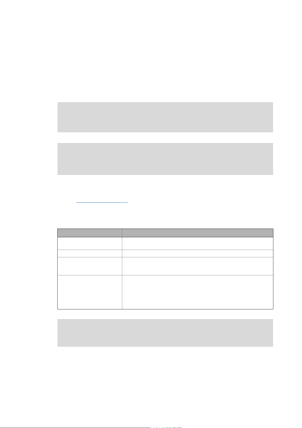
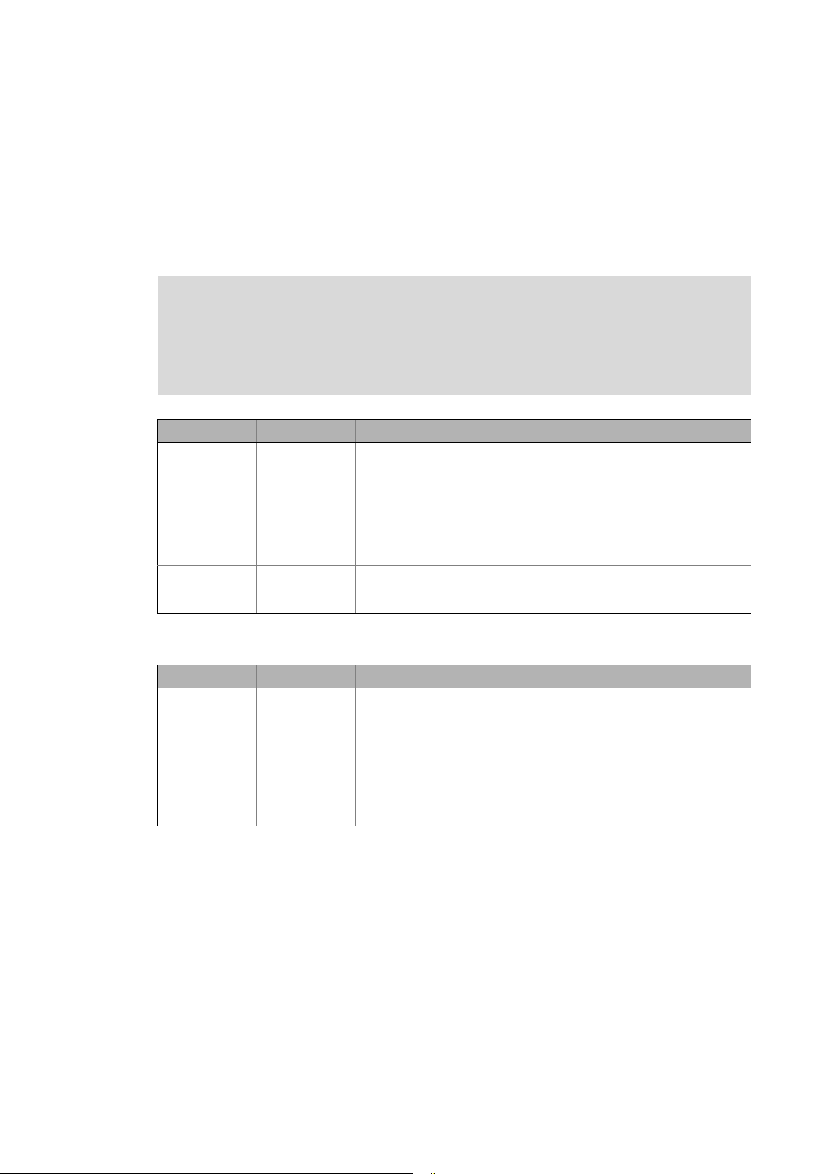
This manual is part of the Controller-based Automation manual collection. The manual collection
consists of the following parts:
Documentation Subject
System manuals • Controller-based Automation - System structure & configuration
(Software) manual • Controller - Parameter setting & configuration
Communication manuals • Controller-based Automation EtherCAT - Commissioning & configuration
Further software manuals • »PLC Designer«
• Visualisation - System structure & configuration
• Controller-based Automation CANopen - Commissioning & configuration
• Controller-based Automation PROFIBUS - Commissioning & configuration
• »Engineer«
• »Global Drive Control« (»GDC«)
• L-force Controller as gateway - Parameter setting & configuration
• »VisiWinNET® Smart«
•»Backup & Restore«
Information on the use of the controller beyond the field of "Controller-based
Automation" can be found in the system manuals tailored to the application
case.
Lenze · Servo Inverter i700 | Application Sample · DMS 1.0 EN - 09/2012 - TD11 3
About this documentation
_ _ _ _ _ _ _ _ _ _ _ _ _ _ _ _ _ _ _ _ _ _ _ _ _ _ _ _ _ _ _ _ _ _ _ _ _ _ _ _ _ _ _ _ _ _ _ _ _ _ _ _ _ _ _ _ _ _ _ _ _ _ _ _
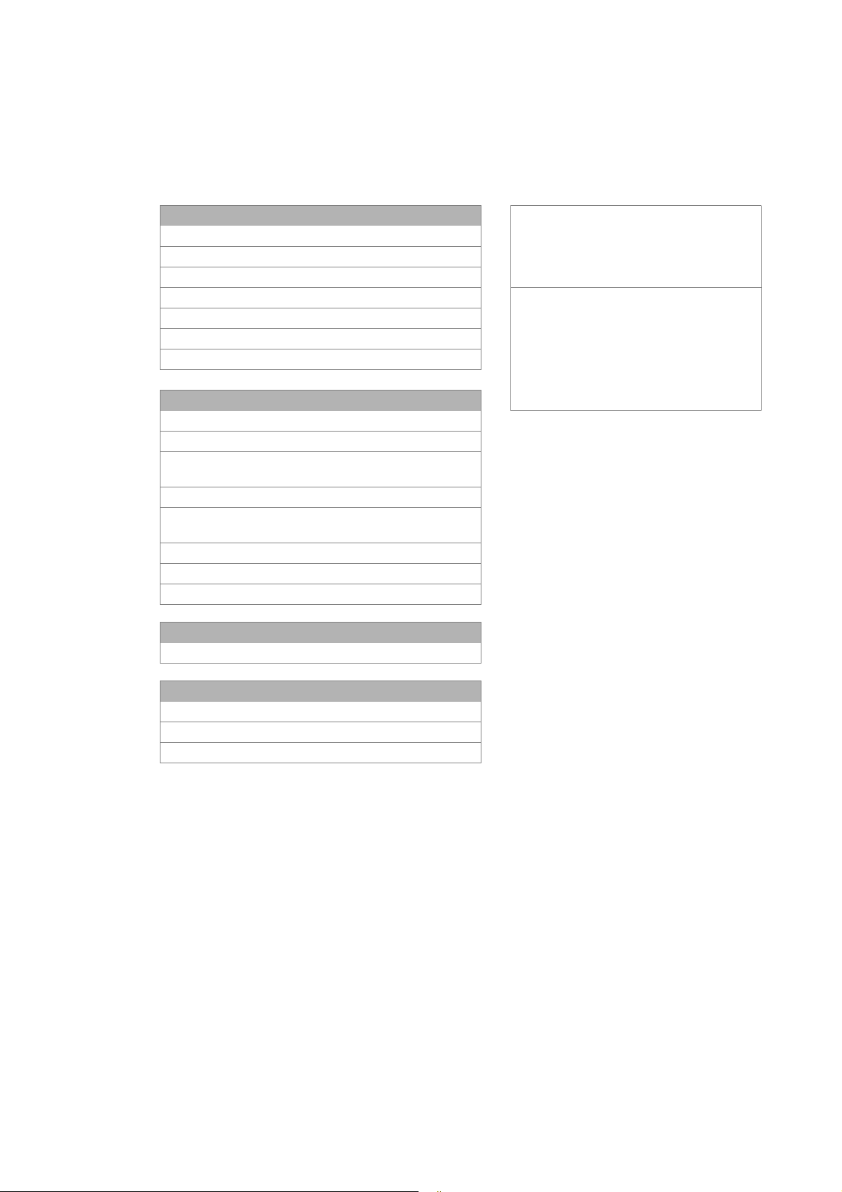
More technical documentation for Lenze components
More information on Lenze components that can be used in connection with Controller-based
automation can be found in the following documentation:
Mounting & wiring Symbols:
MAs Controller Printed documentation
MA i700 servo inverter Online help / PDF file
MAs Servo Drives 9400
MAs Inverter Drives 8400 Abbreviation:
MA I/O system 1000 (EPM-Sxxx) BA Operating instructions
MAs for communication cards (MC-xxx) KHB Communication manual
MAs for communication modules MA Mounting instructions
SW Software manual
Parameterisation, configuration, commissioning SHB System manual
SW L-force Controller
SW Servo-Inverter i700
SW Servo Drive 9400 HighLine/PLC /
Regenerative power supply module
9400 HighLine commissioning guidelines
SW Inverter Drives 8400
StateLine/HighLine/TopLine
SHB I/O system 1000 (EPM-Sxxx)
BAs for servo system ECS (ECSxE, ECSxM)
KHBs for communication modules
Programming
SW 9400 function library
Reuse
SW Application Sample i700
SW Application Samples
SW ApplicationTemplate
Target group
This documentation is directed at all persons who commission and program the Lenze Teachware
case i700 on the basis of the "Application Sample i700" sample project in the context of "Controllerbased Automation".
Screenshots/application examples
All screenshots in this documentation are application examples. Depending on the firmware
version of the Lenze devices and software version of the engineering tools installed (»PLC
Designer«), the screenshots in this documentation may deviate from the screen representation.
4 Lenze · Servo Inverter i700 | Application Sample · DMS 1.0 EN - 09/2012 - TD11

About this documentation
_ _ _ _ _ _ _ _ _ _ _ _ _ _ _ _ _ _ _ _ _ _ _ _ _ _ _ _ _ _ _ _ _ _ _ _ _ _ _ _ _ _ _ _ _ _ _ _ _ _ _ _ _ _ _ _ _ _ _ _ _ _ _ _
Validity information
The information in this documentation is valid for the following Lenze software:
Software From software version
»PLC Designer« 3.3.x
Lenze · Servo Inverter i700 | Application Sample · DMS 1.0 EN - 09/2012 - TD11 5
About this documentation
Document history
_ _ _ _ _ _ _ _ _ _ _ _ _ _ _ _ _ _ _ _ _ _ _ _ _ _ _ _ _ _ _ _ _ _ _ _ _ _ _ _ _ _ _ _ _ _ _ _ _ _ _ _ _ _ _ _ _ _ _ _ _ _ _ _
1.1 Document history
Version Description
1.0 09/2012 TD11 First edition
1.2 Conventions used
This documentation uses the following conventions to distinguish between different types of
information:
Type of information Display Examples/notes
Numbers
Decimal separator Point The decimal point is generally used.
Example: 1234.56
Text
Version information Text colour blue All pieces of information that only apply to or from a certain
Program name » « »PLC Designer«...
Window Italics The Message window... / The Options ... dialog box
Variable name By setting bEnable to TRUE...
Control element Bold The OK... button / The Copy... command / The Properties...
Sequence of menu
commands
Shortcut <Bold> Use <F1> to open the online help.
Hyperlink underlined
Symbols
Page reference ( 6) Reference to further information: Page number in PDF file.
Step-by-step instructions
controller software version are identified accordingly in this
documentation.
Example: This function extension is available as from
software version V3.0!
tab / The Name ... input field
If the execution of a function requires several commands in
a row, the individual commands are separated by an arrow:
Select File
If a key combination is required for a command, a "+" is
placed between the key identifiers: With <Shift>+<ESC>...
Reference to further information: Hyperlink to further
information.
Step-by-step instructions are marked by a pictograph.
Open to...
6
Lenze · Servo Inverter i700 | Application Sample · DMS 1.0 EN - 09/2012 - TD11
About this documentation
Notes used
_ _ _ _ _ _ _ _ _ _ _ _ _ _ _ _ _ _ _ _ _ _ _ _ _ _ _ _ _ _ _ _ _ _ _ _ _ _ _ _ _ _ _ _ _ _ _ _ _ _ _ _ _ _ _ _ _ _ _ _ _ _ _ _
1.3 Notes used
The following signal words and symbols are used in this documentation to indicate dangers and
important information:
Safety instructions
Structure of safety instructions:
Pictograph and signal word!
(characterises the type and severity of danger)
Note
(describes the danger and informs how to prevent dangerous situations)
Pictograph Signal word Meaning
Danger! Danger of personal injuries through dangerous electrical voltage
Danger! Danger of personal injury through a general source of danger
Stop! Danger of material damage
Reference to an imminent danger that may result in death or serious
personal
injury unless the corresponding measures are taken.
Reference to an imminent danger that may result in death or serious
personal
injury unless the corresponding measures are taken.
Indicates a potential danger that may lead to material damage unless the
corresponding measures are taken.
Application notes
Pictograph Signal word Meaning
Note! Important note for trouble-free operation
Tip! Useful tip for easy handling
Reference to another document
Lenze · Servo Inverter i700 | Application Sample · DMS 1.0 EN - 09/2012 - TD11 7

Safety instructions
_ _ _ _ _ _ _ _ _ _ _ _ _ _ _ _ _ _ _ _ _ _ _ _ _ _ _ _ _ _ _ _ _ _ _ _ _ _ _ _ _ _ _ _ _ _ _ _ _ _ _ _ _ _ _ _ _ _ _ _ _ _ _ _
2 Safety instructions
Please observe the following safety instructions when you want to commission a controller or
system using the »Engineer«.
Read the documentation supplied with the controller or the individual
components of the system carefully before you start to commission the devices
with the »Engineer«!
The device documentation contains safety instructions which must be observed!
Danger!
According to today's scientific knowledge it is not possible to ensure absolute freedom
from defects of a software.
If required, systems with integrated controllers have to be equipped with additional
monitoring and protective equipment in accordance with the safety regulations valid in
each case (e.g. law on technical equipment, regulations for the prevention of accidents),
so that an impermissible operating status does not endanger persons or equipment.
During commissioning persons must keep a safe distance from the motor or the
machine parts driven by the motor. Otherwise there would be a risk of injury by the
moving machine parts.
Stop!
If you change parameters in the »PLC Designer« during an online connection to the
device is established, the changes are directly accepted in the device!
An incorrect parameterisation can result in unpredictable motor movements. By an
unintentional direction of rotation, too high speeds or jerky operation, powered
machine parts can be damaged!
8 Lenze · Servo Inverter i700 | Application Sample · DMS 1.0 EN - 09/2012 - TD11
Preconditions
System requirements
_ _ _ _ _ _ _ _ _ _ _ _ _ _ _ _ _ _ _ _ _ _ _ _ _ _ _ _ _ _ _ _ _ _ _ _ _ _ _ _ _ _ _ _ _ _ _ _ _ _ _ _ _ _ _ _ _ _ _ _ _ _ _ _
3 Preconditions
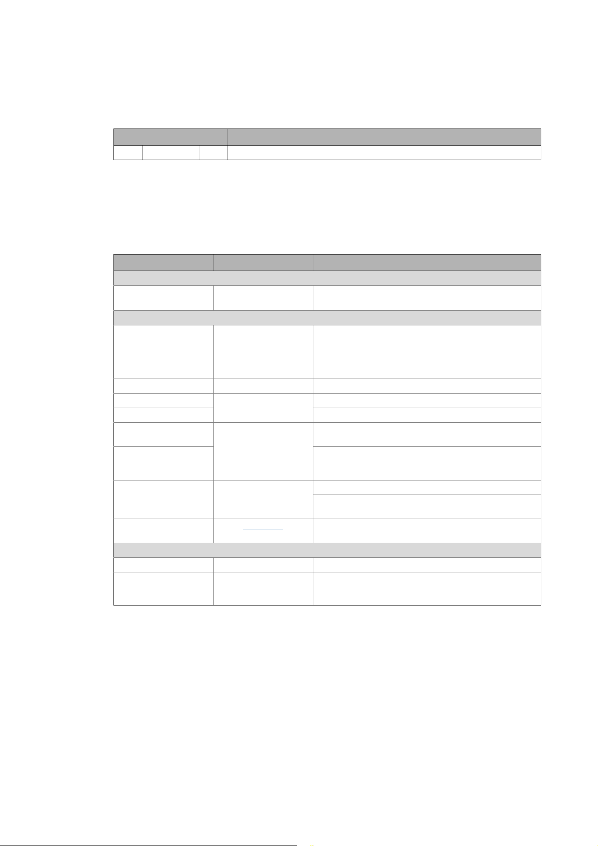
3.1 System requirements
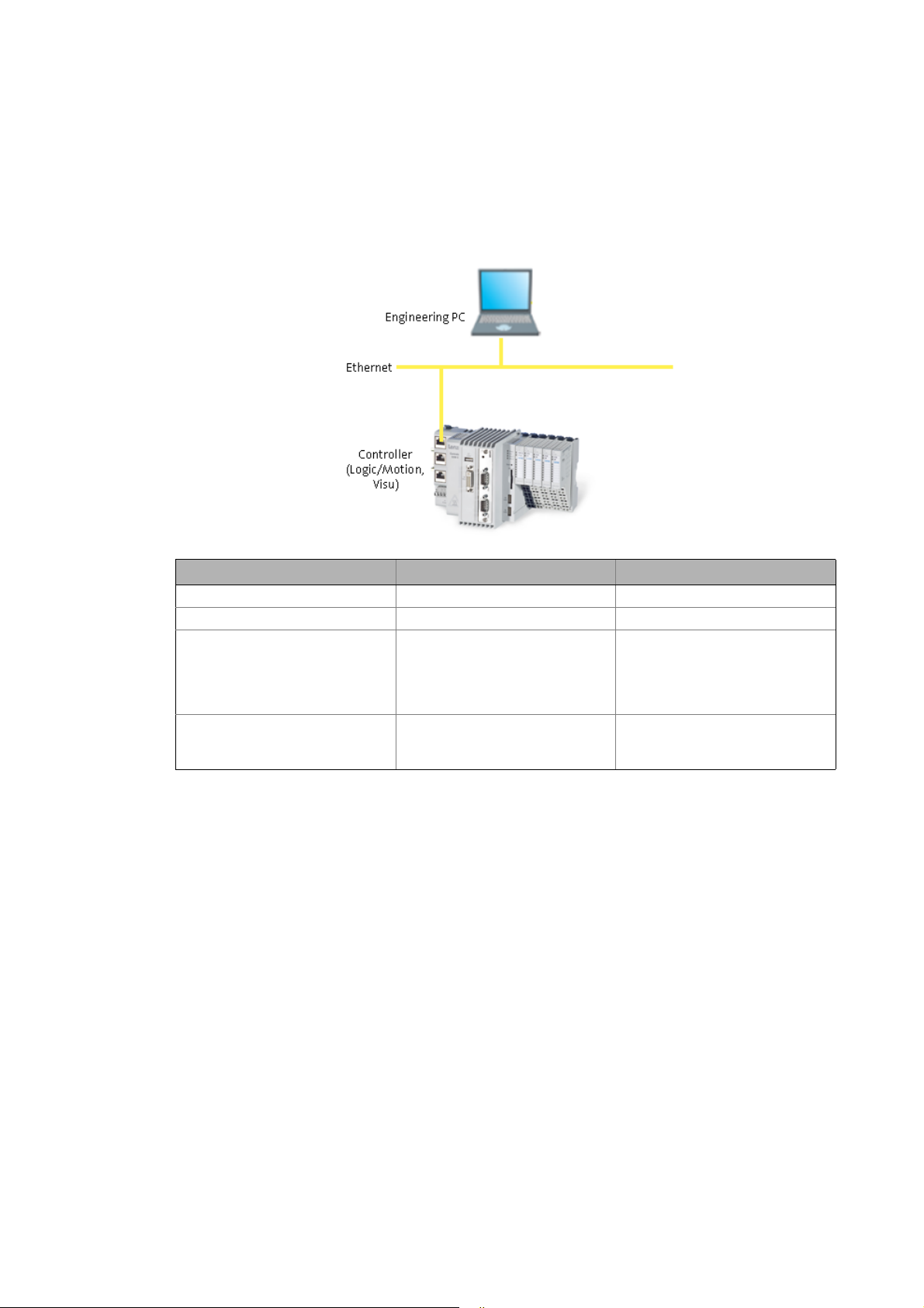
Engineering PC Controller
Hardware PC/notebook PLC (Logic) from firmware V3.3
Operating system Windows XP Windows CE
Required Lenze software »PLC Designer« from V3.3 Runtime Software
Further requirements -Bus system
3.2 Setting up communication to the Controller
• Connect the Engineering PC to the Controller via a network cable. The »PLC Designer« accesses
the Controller via Ethernet.
• Make the IP settings with the »PLC Designer« afterwards.
How to check the communication settings:
1. Go to the Device view and double-click the desired Controller.
2. Make the desired settings on the Communication settings tab.
•Click the Add gateway button to insert a gateway.
•Logic
• Motion (for this purpose, the
project data must be updated:
"Update Device")
• EtherCAT bus system
•EtherCAT node
Lenze · Servo Inverter i700 | Application Sample · DMS 1.0 EN - 09/2012 - TD11 9
Preconditions
Setting up communication to the Controller
_ _ _ _ _ _ _ _ _ _ _ _ _ _ _ _ _ _ _ _ _ _ _ _ _ _ _ _ _ _ _ _ _ _ _ _ _ _ _ _ _ _ _ _ _ _ _ _ _ _ _ _ _ _ _ _ _ _ _ _ _ _ _ _
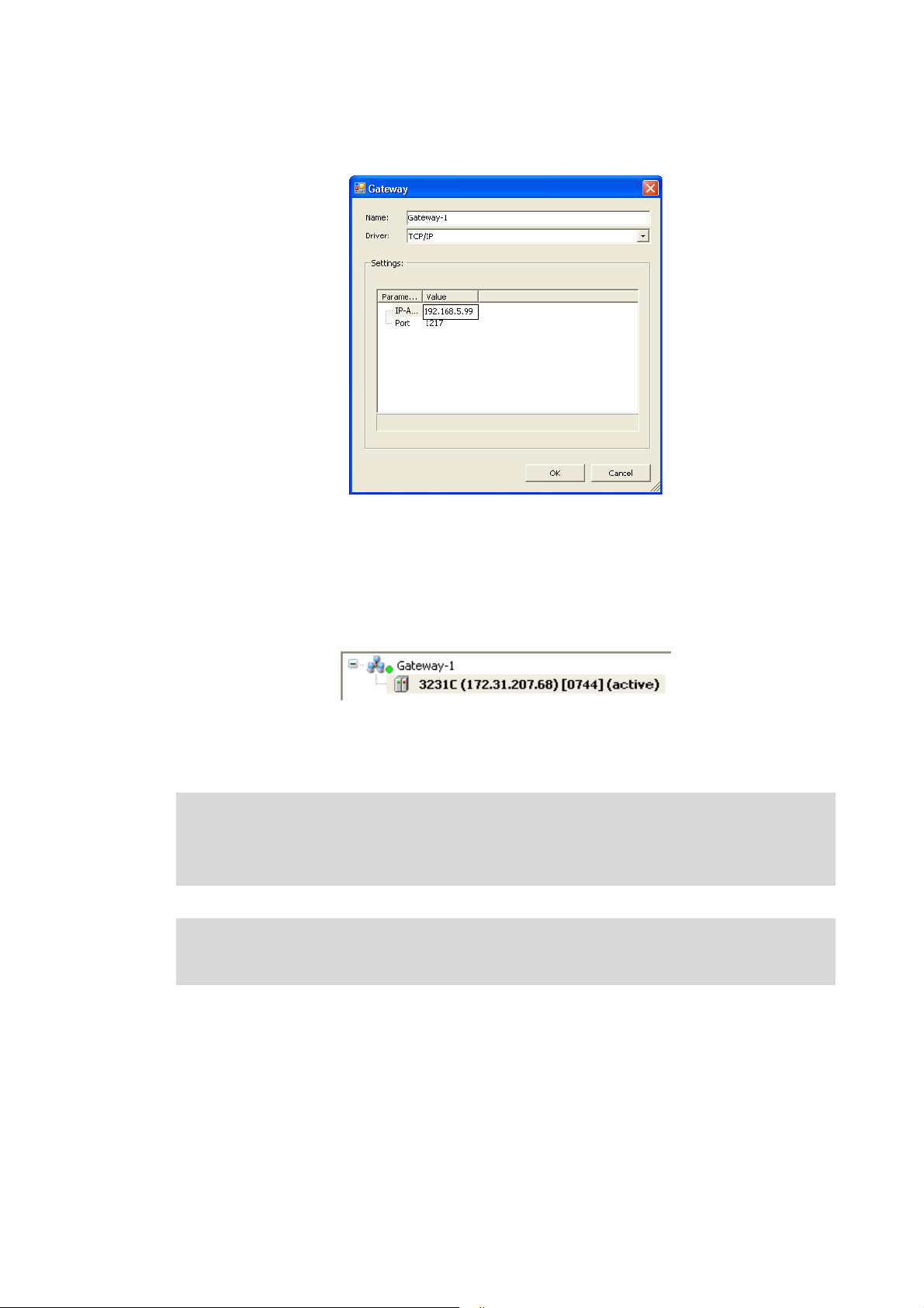
• Enter the desired IP address of the Controller.
[3-1] Example: Enter the IP address of the Controller
3. Click OK to add the Controller as gateway.
4. By double-clicking the desired channel (or clicking the Set active path button) set the
channel selected in the Device View below the gateway as active path for control.
• Thus, all communication actions directly refer to this channel.
• The currently active path is represented in bold in the list and "(active)" is attached:
5. A device represented in italics is set as active path but has not been identified during the
last network scan.
Note!
• During initial commissioning, observe the following predefined IP addresses of the
Controllers: 192.168.5.99
Further information can be found in the following documentation:
• Controller - Parameter setting & Configuration
10
Lenze · Servo Inverter i700 | Application Sample · DMS 1.0 EN - 09/2012 - TD11
 Loading...