

Page 1

Engineering Tools
Drive Solution
Designer
Manual EN
Ä.NS?ä
13455030
L
Page 2

Contents
_ _ _ _ _ _ _ _ _ _ _ _ _ _ _ _ _ _ _ _ _ _ _ _ _ _ _ _ _ _ _ _ _ _ _ _ _ _ _ _ _ _ _ _ _ _ _ _ _ _ _ _ _ _ _ _ _ _ _ _ _ _ _ _
1 Notes on usage _ _ _ _ _ _ _ _ _ _ _ _ _ _ _ _ _ _ _ _ _ _ _ _ _ _ _ _ _ _ _ _ _ _ _ _ _ _ _ _ _ _ _ _ _ 11
1.1 Licencing and contractual conditions _ _ _ _ _ _ _ _ _ _ _ _ _ _ _ _ _ _ _ _ _ _ _ _ _ _ _ _ _ _ _ _ _ _ 11
1.2 Terms and conditions _ _ _ _ _ _ _ _ _ _ _ _ _ _ _ _ _ _ _ _ _ _ _ _ _ _ _ _ _ _ _ _ _ _ _ _ _ _ _ _ _ _ 11
1.3 Important information on the program _ _ _ _ _ _ _ _ _ _ _ _ _ _ _ _ _ _ _ _ _ _ _ _ _ _ _ _ _ _ _ _ 11
2 About this documentation _ _ _ _ _ _ _ _ _ _ _ _ _ _ _ _ _ _ _ _ _ _ _ _ _ _ _ _ _ _ _ _ _ _ _ _ _ _ _ 14
2.1 Structure of the documentation _ _ _ _ _ _ _ _ _ _ _ _ _ _ _ _ _ _ _ _ _ _ _ _ _ _ _ _ _ _ _ _ _ _ _ _ 15
2.2 Conventions used _ _ _ _ _ _ _ _ _ _ _ _ _ _ _ _ _ _ _ _ _ _ _ _ _ _ _ _ _ _ _ _ _ _ _ _ _ _ _ _ _ _ _ _ 16
2.3 Definition of the notes used _ _ _ _ _ _ _ _ _ _ _ _ _ _ _ _ _ _ _ _ _ _ _ _ _ _ _ _ _ _ _ _ _ _ _ _ _ _ 17
3 User interface _ _ _ _ _ _ _ _ _ _ _ _ _ _ _ _ _ _ _ _ _ _ _ _ _ _ _ _ _ _ _ _ _ _ _ _ _ _ _ _ _ _ _ _ _ _ 18
3.1 Control and function elements _ _ _ _ _ _ _ _ _ _ _ _ _ _ _ _ _ _ _ _ _ _ _ _ _ _ _ _ _ _ _ _ _ _ _ _ _ 18
3.1.1 Menu bar _ _ _ _ _ _ _ _ _ _ _ _ _ _ _ _ _ _ _ _ _ _ _ _ _ _ _ _ _ _ _ _ _ _ _ _ _ _ _ _ _ _ _ _ 19
3.1.2 Toolbar _ _ _ _ _ _ _ _ _ _ _ _ _ _ _ _ _ _ _ _ _ _ _ _ _ _ _ _ _ _ _ _ _ _ _ _ _ _ _ _ _ _ _ _ _ 24
3.1.3 Drawing _ _ _ _ _ _ _ _ _ _ _ _ _ _ _ _ _ _ _ _ _ _ _ _ _ _ _ _ _ _ _ _ _ _ _ _ _ _ _ _ _ _ _ _ 27
3.1.4 Navigation tree and result tree _ _ _ _ _ _ _ _ _ _ _ _ _ _ _ _ _ _ _ _ _ _ _ _ _ _ _ _ _ _ _ _ 32
3.1.5 Input area _ _ _ _ _ _ _ _ _ _ _ _ _ _ _ _ _ _ _ _ _ _ _ _ _ _ _ _ _ _ _ _ _ _ _ _ _ _ _ _ _ _ _ _ 33
3.1.6 Notes _ _ _ _ _ _ _ _ _ _ _ _ _ _ _ _ _ _ _ _ _ _ _ _ _ _ _ _ _ _ _ _ _ _ _ _ _ _ _ _ _ _ _ _ _ _ 37
3.2 Shortcuts _ _ _ _ _ _ _ _ _ _ _ _ _ _ _ _ _ _ _ _ _ _ _ _ _ _ _ _ _ _ _ _ _ _ _ _ _ _ _ _ _ _ _ _ _ _ _ _ _ 39
3.3 Closing the program _ _ _ _ _ _ _ _ _ _ _ _ _ _ _ _ _ _ _ _ _ _ _ _ _ _ _ _ _ _ _ _ _ _ _ _ _ _ _ _ _ _ _ 40
4 Setting up the DSD workplace _ _ _ _ _ _ _ _ _ _ _ _ _ _ _ _ _ _ _ _ _ _ _ _ _ _ _ _ _ _ _ _ _ _ _ _ _ 41
4.1 Settings during installation _ _ _ _ _ _ _ _ _ _ _ _ _ _ _ _ _ _ _ _ _ _ _ _ _ _ _ _ _ _ _ _ _ _ _ _ _ _ _ 41
4.2 Registering and activating DSD licence _ _ _ _ _ _ _ _ _ _ _ _ _ _ _ _ _ _ _ _ _ _ _ _ _ _ _ _ _ _ _ _ _ 42
4.3 Communication with the Lenze DSD server _ _ _ _ _ _ _ _ _ _ _ _ _ _ _ _ _ _ _ _ _ _ _ _ _ _ _ _ _ _ 44
4.3.1 Messages _ _ _ _ _ _ _ _ _ _ _ _ _ _ _ _ _ _ _ _ _ _ _ _ _ _ _ _ _ _ _ _ _ _ _ _ _ _ _ _ _ _ _ _ 44
4.3.2 Software updates _ _ _ _ _ _ _ _ _ _ _ _ _ _ _ _ _ _ _ _ _ _ _ _ _ _ _ _ _ _ _ _ _ _ _ _ _ _ _ 45
4.3.3 Assistance in dealing with problems _ _ _ _ _ _ _ _ _ _ _ _ _ _ _ _ _ _ _ _ _ _ _ _ _ _ _ _ _ 45
4.4 Language _ _ _ _ _ _ _ _ _ _ _ _ _ _ _ _ _ _ _ _ _ _ _ _ _ _ _ _ _ _ _ _ _ _ _ _ _ _ _ _ _ _ _ _ _ _ _ _ _ 46
4.5 Settings _ _ _ _ _ _ _ _ _ _ _ _ _ _ _ _ _ _ _ _ _ _ _ _ _ _ _ _ _ _ _ _ _ _ _ _ _ _ _ _ _ _ _ _ _ _ _ _ _ _ 46
4.5.1 "General" register _ _ _ _ _ _ _ _ _ _ _ _ _ _ _ _ _ _ _ _ _ _ _ _ _ _ _ _ _ _ _ _ _ _ _ _ _ _ _ 47
4.5.2 Register "Local area network" _ _ _ _ _ _ _ _ _ _ _ _ _ _ _ _ _ _ _ _ _ _ _ _ _ _ _ _ _ _ _ _ _ 47
4.5.3 "Help" tab _ _ _ _ _ _ _ _ _ _ _ _ _ _ _ _ _ _ _ _ _ _ _ _ _ _ _ _ _ _ _ _ _ _ _ _ _ _ _ _ _ _ _ _ 47
4.5.4 "Motion" register _ _ _ _ _ _ _ _ _ _ _ _ _ _ _ _ _ _ _ _ _ _ _ _ _ _ _ _ _ _ _ _ _ _ _ _ _ _ _ _ 48
4.5.5 "Units" tab _ _ _ _ _ _ _ _ _ _ _ _ _ _ _ _ _ _ _ _ _ _ _ _ _ _ _ _ _ _ _ _ _ _ _ _ _ _ _ _ _ _ _ 48
4.5.6 "Protocol" tab _ _ _ _ _ _ _ _ _ _ _ _ _ _ _ _ _ _ _ _ _ _ _ _ _ _ _ _ _ _ _ _ _ _ _ _ _ _ _ _ _ _ 49
4.5.7 "Customer data" tab _ _ _ _ _ _ _ _ _ _ _ _ _ _ _ _ _ _ _ _ _ _ _ _ _ _ _ _ _ _ _ _ _ _ _ _ _ _ 49
4.5.8 "User data" tab _ _ _ _ _ _ _ _ _ _ _ _ _ _ _ _ _ _ _ _ _ _ _ _ _ _ _ _ _ _ _ _ _ _ _ _ _ _ _ _ _ 50
4.6 User-specific settings _ _ _ _ _ _ _ _ _ _ _ _ _ _ _ _ _ _ _ _ _ _ _ _ _ _ _ _ _ _ _ _ _ _ _ _ _ _ _ _ _ _ 51
4.6.1 User-defined defaults _ _ _ _ _ _ _ _ _ _ _ _ _ _ _ _ _ _ _ _ _ _ _ _ _ _ _ _ _ _ _ _ _ _ _ _ _ 51
5 Managing projects _ _ _ _ _ _ _ _ _ _ _ _ _ _ _ _ _ _ _ _ _ _ _ _ _ _ _ _ _ _ _ _ _ _ _ _ _ _ _ _ _ _ _ _ 52
5.1 Create new project _ _ _ _ _ _ _ _ _ _ _ _ _ _ _ _ _ _ _ _ _ _ _ _ _ _ _ _ _ _ _ _ _ _ _ _ _ _ _ _ _ _ _ 52
5.1.1 Login template _ _ _ _ _ _ _ _ _ _ _ _ _ _ _ _ _ _ _ _ _ _ _ _ _ _ _ _ _ _ _ _ _ _ _ _ _ _ _ _ _ 52
5.2 Open project _ _ _ _ _ _ _ _ _ _ _ _ _ _ _ _ _ _ _ _ _ _ _ _ _ _ _ _ _ _ _ _ _ _ _ _ _ _ _ _ _ _ _ _ _ _ _ 54
5.2.1 Displaying the project in the project viewer _ _ _ _ _ _ _ _ _ _ _ _ _ _ _ _ _ _ _ _ _ _ _ _ _ 54
5.3 Saving the project _ _ _ _ _ _ _ _ _ _ _ _ _ _ _ _ _ _ _ _ _ _ _ _ _ _ _ _ _ _ _ _ _ _ _ _ _ _ _ _ _ _ _ _ 54
6 Drive dimensioning tools _ _ _ _ _ _ _ _ _ _ _ _ _ _ _ _ _ _ _ _ _ _ _ _ _ _ _ _ _ _ _ _ _ _ _ _ _ _ _ _ 55
6.1 Data collection via checklists _ _ _ _ _ _ _ _ _ _ _ _ _ _ _ _ _ _ _ _ _ _ _ _ _ _ _ _ _ _ _ _ _ _ _ _ _ _ 55
6.2 Optimising drive solutions _ _ _ _ _ _ _ _ _ _ _ _ _ _ _ _ _ _ _ _ _ _ _ _ _ _ _ _ _ _ _ _ _ _ _ _ _ _ _ 56
6.2.1 Creating an alternative _ _ _ _ _ _ _ _ _ _ _ _ _ _ _ _ _ _ _ _ _ _ _ _ _ _ _ _ _ _ _ _ _ _ _ _ 57
6.2.2 Application Tuner _ _ _ _ _ _ _ _ _ _ _ _ _ _ _ _ _ _ _ _ _ _ _ _ _ _ _ _ _ _ _ _ _ _ _ _ _ _ _ 59
6.2.3 Project comparison _ _ _ _ _ _ _ _ _ _ _ _ _ _ _ _ _ _ _ _ _ _ _ _ _ _ _ _ _ _ _ _ _ _ _ _ _ _ _ 61
2 Lenze · Drive Solution Designer · Manual · DMS 4.2 EN · 12/2013 · TD23
Page 3

Contents
_ _ _ _ _ _ _ _ _ _ _ _ _ _ _ _ _ _ _ _ _ _ _ _ _ _ _ _ _ _ _ _ _ _ _ _ _ _ _ _ _ _ _ _ _ _ _ _ _ _ _ _ _ _ _ _ _ _ _ _ _ _ _ _
6.3 Dimensioning "easily and quickly" or "complex and precisely" _ _ _ _ _ _ _ _ _ _ _ _ _ _ _ _ _ _ _ _ 62
6.3.1 Roughly estimated calculation _ _ _ _ _ _ _ _ _ _ _ _ _ _ _ _ _ _ _ _ _ _ _ _ _ _ _ _ _ _ _ _ 63
6.3.2 Product features _ _ _ _ _ _ _ _ _ _ _ _ _ _ _ _ _ _ _ _ _ _ _ _ _ _ _ _ _ _ _ _ _ _ _ _ _ _ _ _ 63
6.4 Cost optimisation factors _ _ _ _ _ _ _ _ _ _ _ _ _ _ _ _ _ _ _ _ _ _ _ _ _ _ _ _ _ _ _ _ _ _ _ _ _ _ _ _ 64
7 Applications _ _ _ _ _ _ _ _ _ _ _ _ _ _ _ _ _ _ _ _ _ _ _ _ _ _ _ _ _ _ _ _ _ _ _ _ _ _ _ _ _ _ _ _ _ _ _ 65
7.1 Overview _ _ _ _ _ _ _ _ _ _ _ _ _ _ _ _ _ _ _ _ _ _ _ _ _ _ _ _ _ _ _ _ _ _ _ _ _ _ _ _ _ _ _ _ _ _ _ _ _ 66
7.2 Basic calculations _ _ _ _ _ _ _ _ _ _ _ _ _ _ _ _ _ _ _ _ _ _ _ _ _ _ _ _ _ _ _ _ _ _ _ _ _ _ _ _ _ _ _ _ 68
7.2.1 Torque _ _ _ _ _ _ _ _ _ _ _ _ _ _ _ _ _ _ _ _ _ _ _ _ _ _ _ _ _ _ _ _ _ _ _ _ _ _ _ _ _ _ _ _ _ 68
7.2.2 Power of the application _ _ _ _ _ _ _ _ _ _ _ _ _ _ _ _ _ _ _ _ _ _ _ _ _ _ _ _ _ _ _ _ _ _ _ _ 69
7.2.3 Motion of the application _ _ _ _ _ _ _ _ _ _ _ _ _ _ _ _ _ _ _ _ _ _ _ _ _ _ _ _ _ _ _ _ _ _ _ 70
7.2.4 Symbols used _ _ _ _ _ _ _ _ _ _ _ _ _ _ _ _ _ _ _ _ _ _ _ _ _ _ _ _ _ _ _ _ _ _ _ _ _ _ _ _ _ _ 71
7.3 Belt drive, rotating _ _ _ _ _ _ _ _ _ _ _ _ _ _ _ _ _ _ _ _ _ _ _ _ _ _ _ _ _ _ _ _ _ _ _ _ _ _ _ _ _ _ _ _ 72
7.3.1 Applications with a horizontal direction of movement _ _ _ _ _ _ _ _ _ _ _ _ _ _ _ _ _ _ _ 73
7.3.2 Applications with a vertical direction of movement _ _ _ _ _ _ _ _ _ _ _ _ _ _ _ _ _ _ _ _ _ 74
7.3.3 Calculations _ _ _ _ _ _ _ _ _ _ _ _ _ _ _ _ _ _ _ _ _ _ _ _ _ _ _ _ _ _ _ _ _ _ _ _ _ _ _ _ _ _ 76
7.3.4 Data for the entry _ _ _ _ _ _ _ _ _ _ _ _ _ _ _ _ _ _ _ _ _ _ _ _ _ _ _ _ _ _ _ _ _ _ _ _ _ _ _ 80
7.4 Omega belt drive _ _ _ _ _ _ _ _ _ _ _ _ _ _ _ _ _ _ _ _ _ _ _ _ _ _ _ _ _ _ _ _ _ _ _ _ _ _ _ _ _ _ _ _ 83
7.4.1 Applications with a horizontal direction of movement _ _ _ _ _ _ _ _ _ _ _ _ _ _ _ _ _ _ _ 84
7.4.2 Applications with a vertical direction of movement _ _ _ _ _ _ _ _ _ _ _ _ _ _ _ _ _ _ _ _ _ 85
7.4.3 Calculations _ _ _ _ _ _ _ _ _ _ _ _ _ _ _ _ _ _ _ _ _ _ _ _ _ _ _ _ _ _ _ _ _ _ _ _ _ _ _ _ _ _ 87
7.4.4 Data for the entry _ _ _ _ _ _ _ _ _ _ _ _ _ _ _ _ _ _ _ _ _ _ _ _ _ _ _ _ _ _ _ _ _ _ _ _ _ _ _ 91
7.5 Rack drive _ _ _ _ _ _ _ _ _ _ _ _ _ _ _ _ _ _ _ _ _ _ _ _ _ _ _ _ _ _ _ _ _ _ _ _ _ _ _ _ _ _ _ _ _ _ _ _ 94
7.5.1 Calculations _ _ _ _ _ _ _ _ _ _ _ _ _ _ _ _ _ _ _ _ _ _ _ _ _ _ _ _ _ _ _ _ _ _ _ _ _ _ _ _ _ _ 94
7.5.2 Data for the entry _ _ _ _ _ _ _ _ _ _ _ _ _ _ _ _ _ _ _ _ _ _ _ _ _ _ _ _ _ _ _ _ _ _ _ _ _ _ _ 97
7.6 Spindle drive _ _ _ _ _ _ _ _ _ _ _ _ _ _ _ _ _ _ _ _ _ _ _ _ _ _ _ _ _ _ _ _ _ _ _ _ _ _ _ _ _ _ _ _ _ _ _ 100
7.6.1 Calculations _ _ _ _ _ _ _ _ _ _ _ _ _ _ _ _ _ _ _ _ _ _ _ _ _ _ _ _ _ _ _ _ _ _ _ _ _ _ _ _ _ _ 100
7.6.2 Data for the entry _ _ _ _ _ _ _ _ _ _ _ _ _ _ _ _ _ _ _ _ _ _ _ _ _ _ _ _ _ _ _ _ _ _ _ _ _ _ _ 103
7.7 Wheel drive _ _ _ _ _ _ _ _ _ _ _ _ _ _ _ _ _ _ _ _ _ _ _ _ _ _ _ _ _ _ _ _ _ _ _ _ _ _ _ _ _ _ _ _ _ _ _ 106
7.7.1 Calculations _ _ _ _ _ _ _ _ _ _ _ _ _ _ _ _ _ _ _ _ _ _ _ _ _ _ _ _ _ _ _ _ _ _ _ _ _ _ _ _ _ _ 107
7.7.2 Data for the entry _ _ _ _ _ _ _ _ _ _ _ _ _ _ _ _ _ _ _ _ _ _ _ _ _ _ _ _ _ _ _ _ _ _ _ _ _ _ _ 109
7.8 Hoist drive without counterweight _ _ _ _ _ _ _ _ _ _ _ _ _ _ _ _ _ _ _ _ _ _ _ _ _ _ _ _ _ _ _ _ _ _ _ 113
7.8.1 Calculations _ _ _ _ _ _ _ _ _ _ _ _ _ _ _ _ _ _ _ _ _ _ _ _ _ _ _ _ _ _ _ _ _ _ _ _ _ _ _ _ _ _ 114
7.8.2 Data for the entry _ _ _ _ _ _ _ _ _ _ _ _ _ _ _ _ _ _ _ _ _ _ _ _ _ _ _ _ _ _ _ _ _ _ _ _ _ _ _ 119
7.9 Hoist drive with counterweight _ _ _ _ _ _ _ _ _ _ _ _ _ _ _ _ _ _ _ _ _ _ _ _ _ _ _ _ _ _ _ _ _ _ _ _ _ 122
7.9.1 Calculations _ _ _ _ _ _ _ _ _ _ _ _ _ _ _ _ _ _ _ _ _ _ _ _ _ _ _ _ _ _ _ _ _ _ _ _ _ _ _ _ _ _ 123
7.9.2 Data for the entry _ _ _ _ _ _ _ _ _ _ _ _ _ _ _ _ _ _ _ _ _ _ _ _ _ _ _ _ _ _ _ _ _ _ _ _ _ _ _ 127
7.10 Chain conveyor _ _ _ _ _ _ _ _ _ _ _ _ _ _ _ _ _ _ _ _ _ _ _ _ _ _ _ _ _ _ _ _ _ _ _ _ _ _ _ _ _ _ _ _ _ 132
7.10.1 Calculations _ _ _ _ _ _ _ _ _ _ _ _ _ _ _ _ _ _ _ _ _ _ _ _ _ _ _ _ _ _ _ _ _ _ _ _ _ _ _ _ _ _ 132
7.10.2 Data for the entry _ _ _ _ _ _ _ _ _ _ _ _ _ _ _ _ _ _ _ _ _ _ _ _ _ _ _ _ _ _ _ _ _ _ _ _ _ _ _ 135
7.11 Roller conveyor _ _ _ _ _ _ _ _ _ _ _ _ _ _ _ _ _ _ _ _ _ _ _ _ _ _ _ _ _ _ _ _ _ _ _ _ _ _ _ _ _ _ _ _ _ _ 137
7.11.1 Calculations _ _ _ _ _ _ _ _ _ _ _ _ _ _ _ _ _ _ _ _ _ _ _ _ _ _ _ _ _ _ _ _ _ _ _ _ _ _ _ _ _ _ 137
7.11.2 Data for the entry _ _ _ _ _ _ _ _ _ _ _ _ _ _ _ _ _ _ _ _ _ _ _ _ _ _ _ _ _ _ _ _ _ _ _ _ _ _ _ 140
7.12 Belt conveyors for unit loads _ _ _ _ _ _ _ _ _ _ _ _ _ _ _ _ _ _ _ _ _ _ _ _ _ _ _ _ _ _ _ _ _ _ _ _ _ _ 144
7.12.1 Calculations _ _ _ _ _ _ _ _ _ _ _ _ _ _ _ _ _ _ _ _ _ _ _ _ _ _ _ _ _ _ _ _ _ _ _ _ _ _ _ _ _ _ 144
7.12.2 Data for the entry _ _ _ _ _ _ _ _ _ _ _ _ _ _ _ _ _ _ _ _ _ _ _ _ _ _ _ _ _ _ _ _ _ _ _ _ _ _ _ 146
7.13 Belt conveyor for bulk material _ _ _ _ _ _ _ _ _ _ _ _ _ _ _ _ _ _ _ _ _ _ _ _ _ _ _ _ _ _ _ _ _ _ _ _ _ 149
7.13.1 Calculations _ _ _ _ _ _ _ _ _ _ _ _ _ _ _ _ _ _ _ _ _ _ _ _ _ _ _ _ _ _ _ _ _ _ _ _ _ _ _ _ _ _ 149
7.13.2 Data for the entry _ _ _ _ _ _ _ _ _ _ _ _ _ _ _ _ _ _ _ _ _ _ _ _ _ _ _ _ _ _ _ _ _ _ _ _ _ _ _ 152
7.14 Synchronous drive - single roll _ _ _ _ _ _ _ _ _ _ _ _ _ _ _ _ _ _ _ _ _ _ _ _ _ _ _ _ _ _ _ _ _ _ _ _ _ 156
7.14.1 Calculations _ _ _ _ _ _ _ _ _ _ _ _ _ _ _ _ _ _ _ _ _ _ _ _ _ _ _ _ _ _ _ _ _ _ _ _ _ _ _ _ _ _ 157
7.14.2 Data for the entry _ _ _ _ _ _ _ _ _ _ _ _ _ _ _ _ _ _ _ _ _ _ _ _ _ _ _ _ _ _ _ _ _ _ _ _ _ _ _ 158
7.15 Synchronous drive of squeegees _ _ _ _ _ _ _ _ _ _ _ _ _ _ _ _ _ _ _ _ _ _ _ _ _ _ _ _ _ _ _ _ _ _ _ _ 162
7.15.1 Calculations _ _ _ _ _ _ _ _ _ _ _ _ _ _ _ _ _ _ _ _ _ _ _ _ _ _ _ _ _ _ _ _ _ _ _ _ _ _ _ _ _ _ 163
7.15.2 Data for the entry _ _ _ _ _ _ _ _ _ _ _ _ _ _ _ _ _ _ _ _ _ _ _ _ _ _ _ _ _ _ _ _ _ _ _ _ _ _ _ 165
Lenze · Drive Solution Designer · Manual · DMS 4.2 EN · 12/2013 · TD23 3
Page 4

Contents
_ _ _ _ _ _ _ _ _ _ _ _ _ _ _ _ _ _ _ _ _ _ _ _ _ _ _ _ _ _ _ _ _ _ _ _ _ _ _ _ _ _ _ _ _ _ _ _ _ _ _ _ _ _ _ _ _ _ _ _ _ _ _ _
7.16 General rotary drive _ _ _ _ _ _ _ _ _ _ _ _ _ _ _ _ _ _ _ _ _ _ _ _ _ _ _ _ _ _ _ _ _ _ _ _ _ _ _ _ _ _ _ 168
7.16.1 Calculations _ _ _ _ _ _ _ _ _ _ _ _ _ _ _ _ _ _ _ _ _ _ _ _ _ _ _ _ _ _ _ _ _ _ _ _ _ _ _ _ _ _ 168
7.16.2 Data for the entry _ _ _ _ _ _ _ _ _ _ _ _ _ _ _ _ _ _ _ _ _ _ _ _ _ _ _ _ _ _ _ _ _ _ _ _ _ _ _ 169
7.17 Rotary table drive _ _ _ _ _ _ _ _ _ _ _ _ _ _ _ _ _ _ _ _ _ _ _ _ _ _ _ _ _ _ _ _ _ _ _ _ _ _ _ _ _ _ _ _ 170
7.17.1 Calculations _ _ _ _ _ _ _ _ _ _ _ _ _ _ _ _ _ _ _ _ _ _ _ _ _ _ _ _ _ _ _ _ _ _ _ _ _ _ _ _ _ _ 170
7.17.2 Data for the entry _ _ _ _ _ _ _ _ _ _ _ _ _ _ _ _ _ _ _ _ _ _ _ _ _ _ _ _ _ _ _ _ _ _ _ _ _ _ _ 171
7.18 Pump _ _ _ _ _ _ _ _ _ _ _ _ _ _ _ _ _ _ _ _ _ _ _ _ _ _ _ _ _ _ _ _ _ _ _ _ _ _ _ _ _ _ _ _ _ _ _ _ _ _ _ 173
7.18.1 Calculations _ _ _ _ _ _ _ _ _ _ _ _ _ _ _ _ _ _ _ _ _ _ _ _ _ _ _ _ _ _ _ _ _ _ _ _ _ _ _ _ _ _ 173
7.18.2 Data for the entry _ _ _ _ _ _ _ _ _ _ _ _ _ _ _ _ _ _ _ _ _ _ _ _ _ _ _ _ _ _ _ _ _ _ _ _ _ _ _ 175
7.19 Fan _ _ _ _ _ _ _ _ _ _ _ _ _ _ _ _ _ _ _ _ _ _ _ _ _ _ _ _ _ _ _ _ _ _ _ _ _ _ _ _ _ _ _ _ _ _ _ _ _ _ _ _ 177
7.19.1 Calculations _ _ _ _ _ _ _ _ _ _ _ _ _ _ _ _ _ _ _ _ _ _ _ _ _ _ _ _ _ _ _ _ _ _ _ _ _ _ _ _ _ _ 177
7.19.2 Data for the entry _ _ _ _ _ _ _ _ _ _ _ _ _ _ _ _ _ _ _ _ _ _ _ _ _ _ _ _ _ _ _ _ _ _ _ _ _ _ _ 179
7.20 Importing M-n-operating points _ _ _ _ _ _ _ _ _ _ _ _ _ _ _ _ _ _ _ _ _ _ _ _ _ _ _ _ _ _ _ _ _ _ _ _ 181
7.20.1 Data for the entry _ _ _ _ _ _ _ _ _ _ _ _ _ _ _ _ _ _ _ _ _ _ _ _ _ _ _ _ _ _ _ _ _ _ _ _ _ _ _ 182
7.21 Dimension the multi-axis system _ _ _ _ _ _ _ _ _ _ _ _ _ _ _ _ _ _ _ _ _ _ _ _ _ _ _ _ _ _ _ _ _ _ _ _ 183
7.21.1 Using braking energy _ _ _ _ _ _ _ _ _ _ _ _ _ _ _ _ _ _ _ _ _ _ _ _ _ _ _ _ _ _ _ _ _ _ _ _ _ 183
7.21.2 Combining drive axes _ _ _ _ _ _ _ _ _ _ _ _ _ _ _ _ _ _ _ _ _ _ _ _ _ _ _ _ _ _ _ _ _ _ _ _ _ 185
7.21.3 Combining Lenze products _ _ _ _ _ _ _ _ _ _ _ _ _ _ _ _ _ _ _ _ _ _ _ _ _ _ _ _ _ _ _ _ _ _ 191
7.21.4 Dimensioning _ _ _ _ _ _ _ _ _ _ _ _ _ _ _ _ _ _ _ _ _ _ _ _ _ _ _ _ _ _ _ _ _ _ _ _ _ _ _ _ _ 192
7.21.5 Parameterising projects _ _ _ _ _ _ _ _ _ _ _ _ _ _ _ _ _ _ _ _ _ _ _ _ _ _ _ _ _ _ _ _ _ _ _ _ 193
7.21.6 Defining options _ _ _ _ _ _ _ _ _ _ _ _ _ _ _ _ _ _ _ _ _ _ _ _ _ _ _ _ _ _ _ _ _ _ _ _ _ _ _ _ 195
7.22 Winding drive for rewinder/unwinder _ _ _ _ _ _ _ _ _ _ _ _ _ _ _ _ _ _ _ _ _ _ _ _ _ _ _ _ _ _ _ _ _ 198
7.22.1 Rewinder (single) _ _ _ _ _ _ _ _ _ _ _ _ _ _ _ _ _ _ _ _ _ _ _ _ _ _ _ _ _ _ _ _ _ _ _ _ _ _ _ _ 198
7.22.2 Unwinder (single) _ _ _ _ _ _ _ _ _ _ _ _ _ _ _ _ _ _ _ _ _ _ _ _ _ _ _ _ _ _ _ _ _ _ _ _ _ _ _ 203
7.22.3 Dimensioning strategies _ _ _ _ _ _ _ _ _ _ _ _ _ _ _ _ _ _ _ _ _ _ _ _ _ _ _ _ _ _ _ _ _ _ _ _ 208
7.22.4 Traction-controlled winding drive _ _ _ _ _ _ _ _ _ _ _ _ _ _ _ _ _ _ _ _ _ _ _ _ _ _ _ _ _ _ 210
7.22.5 Checking emergency-off scenarios _ _ _ _ _ _ _ _ _ _ _ _ _ _ _ _ _ _ _ _ _ _ _ _ _ _ _ _ _ _ 211
7.22.6 Application data _ _ _ _ _ _ _ _ _ _ _ _ _ _ _ _ _ _ _ _ _ _ _ _ _ _ _ _ _ _ _ _ _ _ _ _ _ _ _ _ 212
7.22.7 Data for the motion _ _ _ _ _ _ _ _ _ _ _ _ _ _ _ _ _ _ _ _ _ _ _ _ _ _ _ _ _ _ _ _ _ _ _ _ _ _ 219
8Motion design _ _ _ _ _ _ _ _ _ _ _ _ _ _ _ _ _ _ _ _ _ _ _ _ _ _ _ _ _ _ _ _ _ _ _ _ _ _ _ _ _ _ _ _ _ _ 224
8.1 Selection of motion profile _ _ _ _ _ _ _ _ _ _ _ _ _ _ _ _ _ _ _ _ _ _ _ _ _ _ _ _ _ _ _ _ _ _ _ _ _ _ _ 224
8.2 MotionDesigner _ _ _ _ _ _ _ _ _ _ _ _ _ _ _ _ _ _ _ _ _ _ _ _ _ _ _ _ _ _ _ _ _ _ _ _ _ _ _ _ _ _ _ _ _ 225
8.2.1 Control and function elements _ _ _ _ _ _ _ _ _ _ _ _ _ _ _ _ _ _ _ _ _ _ _ _ _ _ _ _ _ _ _ _ 226
8.2.2 Toolbar _ _ _ _ _ _ _ _ _ _ _ _ _ _ _ _ _ _ _ _ _ _ _ _ _ _ _ _ _ _ _ _ _ _ _ _ _ _ _ _ _ _ _ _ _ 227
8.2.3 Screen divider _ _ _ _ _ _ _ _ _ _ _ _ _ _ _ _ _ _ _ _ _ _ _ _ _ _ _ _ _ _ _ _ _ _ _ _ _ _ _ _ _ 228
8.2.4 Object area _ _ _ _ _ _ _ _ _ _ _ _ _ _ _ _ _ _ _ _ _ _ _ _ _ _ _ _ _ _ _ _ _ _ _ _ _ _ _ _ _ _ _ 229
8.2.5 Managing motion profiles _ _ _ _ _ _ _ _ _ _ _ _ _ _ _ _ _ _ _ _ _ _ _ _ _ _ _ _ _ _ _ _ _ _ _ 234
8.2.6 Graphic area _ _ _ _ _ _ _ _ _ _ _ _ _ _ _ _ _ _ _ _ _ _ _ _ _ _ _ _ _ _ _ _ _ _ _ _ _ _ _ _ _ _ 239
8.2.7 Parameter area: Description _ _ _ _ _ _ _ _ _ _ _ _ _ _ _ _ _ _ _ _ _ _ _ _ _ _ _ _ _ _ _ _ _ _ 247
8.2.8 Positioning _ _ _ _ _ _ _ _ _ _ _ _ _ _ _ _ _ _ _ _ _ _ _ _ _ _ _ _ _ _ _ _ _ _ _ _ _ _ _ _ _ _ _ 255
8.2.9 Parameter area: Data for the entry _ _ _ _ _ _ _ _ _ _ _ _ _ _ _ _ _ _ _ _ _ _ _ _ _ _ _ _ _ _ 257
8.2.10 Application notes for motion profiles _ _ _ _ _ _ _ _ _ _ _ _ _ _ _ _ _ _ _ _ _ _ _ _ _ _ _ _ _ 263
8.3 Predefined motion profile according to operating mode _ _ _ _ _ _ _ _ _ _ _ _ _ _ _ _ _ _ _ _ _ _ _ 270
8.3.1 S1, continuous operation _ _ _ _ _ _ _ _ _ _ _ _ _ _ _ _ _ _ _ _ _ _ _ _ _ _ _ _ _ _ _ _ _ _ _ 270
8.3.2 S2, short-term operation _ _ _ _ _ _ _ _ _ _ _ _ _ _ _ _ _ _ _ _ _ _ _ _ _ _ _ _ _ _ _ _ _ _ _ 271
8.3.3 Intermittent operation S3, S4, S5 _ _ _ _ _ _ _ _ _ _ _ _ _ _ _ _ _ _ _ _ _ _ _ _ _ _ _ _ _ _ _ 272
8.3.4 Intermittent load S6, S7 _ _ _ _ _ _ _ _ _ _ _ _ _ _ _ _ _ _ _ _ _ _ _ _ _ _ _ _ _ _ _ _ _ _ _ _ 273
8.3.5 Description of the data for the entry _ _ _ _ _ _ _ _ _ _ _ _ _ _ _ _ _ _ _ _ _ _ _ _ _ _ _ _ _ 274
9 Mains and environment _ _ _ _ _ _ _ _ _ _ _ _ _ _ _ _ _ _ _ _ _ _ _ _ _ _ _ _ _ _ _ _ _ _ _ _ _ _ _ _ _ 277
9.1 Electrical supply system _ _ _ _ _ _ _ _ _ _ _ _ _ _ _ _ _ _ _ _ _ _ _ _ _ _ _ _ _ _ _ _ _ _ _ _ _ _ _ _ _ 277
9.1.1 Power system _ _ _ _ _ _ _ _ _ _ _ _ _ _ _ _ _ _ _ _ _ _ _ _ _ _ _ _ _ _ _ _ _ _ _ _ _ _ _ _ _ 277
4 Lenze · Drive Solution Designer · Manual · DMS 4.2 EN · 12/2013 · TD23
Page 5

Contents
_ _ _ _ _ _ _ _ _ _ _ _ _ _ _ _ _ _ _ _ _ _ _ _ _ _ _ _ _ _ _ _ _ _ _ _ _ _ _ _ _ _ _ _ _ _ _ _ _ _ _ _ _ _ _ _ _ _ _ _ _ _ _ _
9.2 Ambient conditions _ _ _ _ _ _ _ _ _ _ _ _ _ _ _ _ _ _ _ _ _ _ _ _ _ _ _ _ _ _ _ _ _ _ _ _ _ _ _ _ _ _ _ 278
9.2.1 Max. ambient temperature, motor/gearbox _ _ _ _ _ _ _ _ _ _ _ _ _ _ _ _ _ _ _ _ _ _ _ _ _ 278
9.2.2 Max. ambient temperature, inverter _ _ _ _ _ _ _ _ _ _ _ _ _ _ _ _ _ _ _ _ _ _ _ _ _ _ _ _ _ 279
9.2.3 Site altitude _ _ _ _ _ _ _ _ _ _ _ _ _ _ _ _ _ _ _ _ _ _ _ _ _ _ _ _ _ _ _ _ _ _ _ _ _ _ _ _ _ _ 280
9.3 Calculation of the mains current _ _ _ _ _ _ _ _ _ _ _ _ _ _ _ _ _ _ _ _ _ _ _ _ _ _ _ _ _ _ _ _ _ _ _ _ 281
10 Structure of the drive axis _ _ _ _ _ _ _ _ _ _ _ _ _ _ _ _ _ _ _ _ _ _ _ _ _ _ _ _ _ _ _ _ _ _ _ _ _ _ _ _ 282
10.1 Mechanical drive axis _ _ _ _ _ _ _ _ _ _ _ _ _ _ _ _ _ _ _ _ _ _ _ _ _ _ _ _ _ _ _ _ _ _ _ _ _ _ _ _ _ _ 283
10.1.1 Lenze gearbox _ _ _ _ _ _ _ _ _ _ _ _ _ _ _ _ _ _ _ _ _ _ _ _ _ _ _ _ _ _ _ _ _ _ _ _ _ _ _ _ _ 283
10.1.2 Additional drive element _ _ _ _ _ _ _ _ _ _ _ _ _ _ _ _ _ _ _ _ _ _ _ _ _ _ _ _ _ _ _ _ _ _ _ 284
10.1.3 Feedback _ _ _ _ _ _ _ _ _ _ _ _ _ _ _ _ _ _ _ _ _ _ _ _ _ _ _ _ _ _ _ _ _ _ _ _ _ _ _ _ _ _ _ _ 284
10.1.4 Electromechanical brake _ _ _ _ _ _ _ _ _ _ _ _ _ _ _ _ _ _ _ _ _ _ _ _ _ _ _ _ _ _ _ _ _ _ _ _ 284
10.2 Electrical drive axis _ _ _ _ _ _ _ _ _ _ _ _ _ _ _ _ _ _ _ _ _ _ _ _ _ _ _ _ _ _ _ _ _ _ _ _ _ _ _ _ _ _ _ 285
10.2.1 Inverter with mains supply (single-axis application) _ _ _ _ _ _ _ _ _ _ _ _ _ _ _ _ _ _ _ _ _ 285
10.2.2 Inverter with DC supply (multi-axis application) _ _ _ _ _ _ _ _ _ _ _ _ _ _ _ _ _ _ _ _ _ _ _ 285
10.3 Drive concept _ _ _ _ _ _ _ _ _ _ _ _ _ _ _ _ _ _ _ _ _ _ _ _ _ _ _ _ _ _ _ _ _ _ _ _ _ _ _ _ _ _ _ _ _ _ 286
10.3.1 Gearbox features _ _ _ _ _ _ _ _ _ _ _ _ _ _ _ _ _ _ _ _ _ _ _ _ _ _ _ _ _ _ _ _ _ _ _ _ _ _ _ _ 287
10.3.2 Motor properties _ _ _ _ _ _ _ _ _ _ _ _ _ _ _ _ _ _ _ _ _ _ _ _ _ _ _ _ _ _ _ _ _ _ _ _ _ _ _ _ 289
10.3.3 Motor/gearbox: Direct mounting or standard mounting _ _ _ _ _ _ _ _ _ _ _ _ _ _ _ _ _ _ 293
10.3.4 Inverter properties _ _ _ _ _ _ _ _ _ _ _ _ _ _ _ _ _ _ _ _ _ _ _ _ _ _ _ _ _ _ _ _ _ _ _ _ _ _ _ 294
10.3.5 Overview of motor/inverter control types _ _ _ _ _ _ _ _ _ _ _ _ _ _ _ _ _ _ _ _ _ _ _ _ _ _ 300
10.3.6 Selection help: Products for applications (without winders) _ _ _ _ _ _ _ _ _ _ _ _ _ _ _ _ 304
10.3.7 Selection help: Products for winding drive systems _ _ _ _ _ _ _ _ _ _ _ _ _ _ _ _ _ _ _ _ _ 305
10.3.8 Selection help: Control types for winding drive systems _ _ _ _ _ _ _ _ _ _ _ _ _ _ _ _ _ _ 307
11 Drive Dimensioning _ _ _ _ _ _ _ _ _ _ _ _ _ _ _ _ _ _ _ _ _ _ _ _ _ _ _ _ _ _ _ _ _ _ _ _ _ _ _ _ _ _ _ 308
11.1 Preselection of the geared motor _ _ _ _ _ _ _ _ _ _ _ _ _ _ _ _ _ _ _ _ _ _ _ _ _ _ _ _ _ _ _ _ _ _ _ _ 308
11.1.1 Additional moment of inertia _ _ _ _ _ _ _ _ _ _ _ _ _ _ _ _ _ _ _ _ _ _ _ _ _ _ _ _ _ _ _ _ _ 308
11.1.2 Mounting position _ _ _ _ _ _ _ _ _ _ _ _ _ _ _ _ _ _ _ _ _ _ _ _ _ _ _ _ _ _ _ _ _ _ _ _ _ _ _ 309
11.1.3 Average daily operating time _ _ _ _ _ _ _ _ _ _ _ _ _ _ _ _ _ _ _ _ _ _ _ _ _ _ _ _ _ _ _ _ _ 311
11.1.4 Additional drive element (K) _ _ _ _ _ _ _ _ _ _ _ _ _ _ _ _ _ _ _ _ _ _ _ _ _ _ _ _ _ _ _ _ _ _ 311
11.1.5 Minimum ratio (K) _ _ _ _ _ _ _ _ _ _ _ _ _ _ _ _ _ _ _ _ _ _ _ _ _ _ _ _ _ _ _ _ _ _ _ _ _ _ _ 312
11.1.6 Maximum ratio (K) _ _ _ _ _ _ _ _ _ _ _ _ _ _ _ _ _ _ _ _ _ _ _ _ _ _ _ _ _ _ _ _ _ _ _ _ _ _ _ 312
11.2 Motor selection _ _ _ _ _ _ _ _ _ _ _ _ _ _ _ _ _ _ _ _ _ _ _ _ _ _ _ _ _ _ _ _ _ _ _ _ _ _ _ _ _ _ _ _ _ 313
11.2.1 Motors for 87-Hz operation _ _ _ _ _ _ _ _ _ _ _ _ _ _ _ _ _ _ _ _ _ _ _ _ _ _ _ _ _ _ _ _ _ _ 313
11.2.2 Motors for 120-Hz operation _ _ _ _ _ _ _ _ _ _ _ _ _ _ _ _ _ _ _ _ _ _ _ _ _ _ _ _ _ _ _ _ _ 313
11.2.3 Dimensioning guidelines and dimensioning information _ _ _ _ _ _ _ _ _ _ _ _ _ _ _ _ _ _ 314
11.2.4 Field weakening for winding drives _ _ _ _ _ _ _ _ _ _ _ _ _ _ _ _ _ _ _ _ _ _ _ _ _ _ _ _ _ _ 314
11.2.5 M-n characteristic _ _ _ _ _ _ _ _ _ _ _ _ _ _ _ _ _ _ _ _ _ _ _ _ _ _ _ _ _ _ _ _ _ _ _ _ _ _ _ 316
11.2.6 Thermal utilisation _ _ _ _ _ _ _ _ _ _ _ _ _ _ _ _ _ _ _ _ _ _ _ _ _ _ _ _ _ _ _ _ _ _ _ _ _ _ _ 318
11.2.7 Selection table _ _ _ _ _ _ _ _ _ _ _ _ _ _ _ _ _ _ _ _ _ _ _ _ _ _ _ _ _ _ _ _ _ _ _ _ _ _ _ _ _ 319
11.2.8 Load-matching factor _ _ _ _ _ _ _ _ _ _ _ _ _ _ _ _ _ _ _ _ _ _ _ _ _ _ _ _ _ _ _ _ _ _ _ _ _ 321
11.2.9 Radial forces/axial forces _ _ _ _ _ _ _ _ _ _ _ _ _ _ _ _ _ _ _ _ _ _ _ _ _ _ _ _ _ _ _ _ _ _ _ 325
11.3 Mechanical brake selection _ _ _ _ _ _ _ _ _ _ _ _ _ _ _ _ _ _ _ _ _ _ _ _ _ _ _ _ _ _ _ _ _ _ _ _ _ _ _ 326
11.3.1 Spring-applied brake (BFK) _ _ _ _ _ _ _ _ _ _ _ _ _ _ _ _ _ _ _ _ _ _ _ _ _ _ _ _ _ _ _ _ _ _ 327
11.3.2 Permanent magnet holding brake (PMB) _ _ _ _ _ _ _ _ _ _ _ _ _ _ _ _ _ _ _ _ _ _ _ _ _ _ _ 327
11.3.3 Dimensioning criteria _ _ _ _ _ _ _ _ _ _ _ _ _ _ _ _ _ _ _ _ _ _ _ _ _ _ _ _ _ _ _ _ _ _ _ _ _ 328
11.3.4 Holding torque diagram _ _ _ _ _ _ _ _ _ _ _ _ _ _ _ _ _ _ _ _ _ _ _ _ _ _ _ _ _ _ _ _ _ _ _ _ 329
11.3.5 Design _ _ _ _ _ _ _ _ _ _ _ _ _ _ _ _ _ _ _ _ _ _ _ _ _ _ _ _ _ _ _ _ _ _ _ _ _ _ _ _ _ _ _ _ _ 330
11.3.6 Selection table _ _ _ _ _ _ _ _ _ _ _ _ _ _ _ _ _ _ _ _ _ _ _ _ _ _ _ _ _ _ _ _ _ _ _ _ _ _ _ _ _ 331
Lenze · Drive Solution Designer · Manual · DMS 4.2 EN · 12/2013 · TD23 5
Page 6

Contents
_ _ _ _ _ _ _ _ _ _ _ _ _ _ _ _ _ _ _ _ _ _ _ _ _ _ _ _ _ _ _ _ _ _ _ _ _ _ _ _ _ _ _ _ _ _ _ _ _ _ _ _ _ _ _ _ _ _ _ _ _ _ _ _
11.4 Lenze gearbox selection _ _ _ _ _ _ _ _ _ _ _ _ _ _ _ _ _ _ _ _ _ _ _ _ _ _ _ _ _ _ _ _ _ _ _ _ _ _ _ _ _ 332
11.4.1 Check of the torque load _ _ _ _ _ _ _ _ _ _ _ _ _ _ _ _ _ _ _ _ _ _ _ _ _ _ _ _ _ _ _ _ _ _ _ _ 332
11.4.2 Check of the speed load _ _ _ _ _ _ _ _ _ _ _ _ _ _ _ _ _ _ _ _ _ _ _ _ _ _ _ _ _ _ _ _ _ _ _ _ 337
11.4.3 Radial and axial forces _ _ _ _ _ _ _ _ _ _ _ _ _ _ _ _ _ _ _ _ _ _ _ _ _ _ _ _ _ _ _ _ _ _ _ _ _ 337
11.4.4 M-n characteristic _ _ _ _ _ _ _ _ _ _ _ _ _ _ _ _ _ _ _ _ _ _ _ _ _ _ _ _ _ _ _ _ _ _ _ _ _ _ _ 338
11.4.5 Thermal utilisation _ _ _ _ _ _ _ _ _ _ _ _ _ _ _ _ _ _ _ _ _ _ _ _ _ _ _ _ _ _ _ _ _ _ _ _ _ _ _ 339
11.4.6 Selection table _ _ _ _ _ _ _ _ _ _ _ _ _ _ _ _ _ _ _ _ _ _ _ _ _ _ _ _ _ _ _ _ _ _ _ _ _ _ _ _ _ 341
11.5 Selection of an additional drive element _ _ _ _ _ _ _ _ _ _ _ _ _ _ _ _ _ _ _ _ _ _ _ _ _ _ _ _ _ _ _ _ 344
11.5.1 Type identifier _ _ _ _ _ _ _ _ _ _ _ _ _ _ _ _ _ _ _ _ _ _ _ _ _ _ _ _ _ _ _ _ _ _ _ _ _ _ _ _ _ 344
11.5.2 Ratio _ _ _ _ _ _ _ _ _ _ _ _ _ _ _ _ _ _ _ _ _ _ _ _ _ _ _ _ _ _ _ _ _ _ _ _ _ _ _ _ _ _ _ _ _ _ 344
11.5.3 Efficiency _ _ _ _ _ _ _ _ _ _ _ _ _ _ _ _ _ _ _ _ _ _ _ _ _ _ _ _ _ _ _ _ _ _ _ _ _ _ _ _ _ _ _ _ 344
11.5.4 Moment of inertia _ _ _ _ _ _ _ _ _ _ _ _ _ _ _ _ _ _ _ _ _ _ _ _ _ _ _ _ _ _ _ _ _ _ _ _ _ _ _ 344
11.5.5 Permissible torque _ _ _ _ _ _ _ _ _ _ _ _ _ _ _ _ _ _ _ _ _ _ _ _ _ _ _ _ _ _ _ _ _ _ _ _ _ _ _ 345
11.5.6 Constant torque loss _ _ _ _ _ _ _ _ _ _ _ _ _ _ _ _ _ _ _ _ _ _ _ _ _ _ _ _ _ _ _ _ _ _ _ _ _ _ 345
11.6 Inverters _ _ _ _ _ _ _ _ _ _ _ _ _ _ _ _ _ _ _ _ _ _ _ _ _ _ _ _ _ _ _ _ _ _ _ _ _ _ _ _ _ _ _ _ _ _ _ _ _ 346
11.6.1 Dimensioning criteria _ _ _ _ _ _ _ _ _ _ _ _ _ _ _ _ _ _ _ _ _ _ _ _ _ _ _ _ _ _ _ _ _ _ _ _ _ 346
11.6.2 Preselection _ _ _ _ _ _ _ _ _ _ _ _ _ _ _ _ _ _ _ _ _ _ _ _ _ _ _ _ _ _ _ _ _ _ _ _ _ _ _ _ _ _ 353
11.6.3 Selection table _ _ _ _ _ _ _ _ _ _ _ _ _ _ _ _ _ _ _ _ _ _ _ _ _ _ _ _ _ _ _ _ _ _ _ _ _ _ _ _ _ 355
11.7 Motor components _ _ _ _ _ _ _ _ _ _ _ _ _ _ _ _ _ _ _ _ _ _ _ _ _ _ _ _ _ _ _ _ _ _ _ _ _ _ _ _ _ _ _ 357
11.7.1 Feedback selection _ _ _ _ _ _ _ _ _ _ _ _ _ _ _ _ _ _ _ _ _ _ _ _ _ _ _ _ _ _ _ _ _ _ _ _ _ _ _ 357
11.7.2 Selection table _ _ _ _ _ _ _ _ _ _ _ _ _ _ _ _ _ _ _ _ _ _ _ _ _ _ _ _ _ _ _ _ _ _ _ _ _ _ _ _ _ 360
12 Components in the DC bus _ _ _ _ _ _ _ _ _ _ _ _ _ _ _ _ _ _ _ _ _ _ _ _ _ _ _ _ _ _ _ _ _ _ _ _ _ _ _ 361
12.1 Supply concept _ _ _ _ _ _ _ _ _ _ _ _ _ _ _ _ _ _ _ _ _ _ _ _ _ _ _ _ _ _ _ _ _ _ _ _ _ _ _ _ _ _ _ _ _ _ 361
12.2 9400 power supply module _ _ _ _ _ _ _ _ _ _ _ _ _ _ _ _ _ _ _ _ _ _ _ _ _ _ _ _ _ _ _ _ _ _ _ _ _ _ _ 362
12.2.1 Selection table _ _ _ _ _ _ _ _ _ _ _ _ _ _ _ _ _ _ _ _ _ _ _ _ _ _ _ _ _ _ _ _ _ _ _ _ _ _ _ _ _ 362
12.2.2 Utilisation _ _ _ _ _ _ _ _ _ _ _ _ _ _ _ _ _ _ _ _ _ _ _ _ _ _ _ _ _ _ _ _ _ _ _ _ _ _ _ _ _ _ _ 363
12.3 9400 regenerative power supply module _ _ _ _ _ _ _ _ _ _ _ _ _ _ _ _ _ _ _ _ _ _ _ _ _ _ _ _ _ _ _ 364
12.3.1 Selection table _ _ _ _ _ _ _ _ _ _ _ _ _ _ _ _ _ _ _ _ _ _ _ _ _ _ _ _ _ _ _ _ _ _ _ _ _ _ _ _ _ 364
12.3.2 Utilisation _ _ _ _ _ _ _ _ _ _ _ _ _ _ _ _ _ _ _ _ _ _ _ _ _ _ _ _ _ _ _ _ _ _ _ _ _ _ _ _ _ _ _ 365
12.4 i700 power supply module _ _ _ _ _ _ _ _ _ _ _ _ _ _ _ _ _ _ _ _ _ _ _ _ _ _ _ _ _ _ _ _ _ _ _ _ _ _ _ 366
12.4.1 Selection table _ _ _ _ _ _ _ _ _ _ _ _ _ _ _ _ _ _ _ _ _ _ _ _ _ _ _ _ _ _ _ _ _ _ _ _ _ _ _ _ _ 366
12.4.2 Utilisation _ _ _ _ _ _ _ _ _ _ _ _ _ _ _ _ _ _ _ _ _ _ _ _ _ _ _ _ _ _ _ _ _ _ _ _ _ _ _ _ _ _ _ 367
12.5 Selection of components _ _ _ _ _ _ _ _ _ _ _ _ _ _ _ _ _ _ _ _ _ _ _ _ _ _ _ _ _ _ _ _ _ _ _ _ _ _ _ _ 367
12.6 Brake resistor selection _ _ _ _ _ _ _ _ _ _ _ _ _ _ _ _ _ _ _ _ _ _ _ _ _ _ _ _ _ _ _ _ _ _ _ _ _ _ _ _ _ 368
12.6.1 Number of integrated brake transistors _ _ _ _ _ _ _ _ _ _ _ _ _ _ _ _ _ _ _ _ _ _ _ _ _ _ _ 368
12.6.2 Interconnection of brake resistors _ _ _ _ _ _ _ _ _ _ _ _ _ _ _ _ _ _ _ _ _ _ _ _ _ _ _ _ _ _ 369
12.6.3 Selection table _ _ _ _ _ _ _ _ _ _ _ _ _ _ _ _ _ _ _ _ _ _ _ _ _ _ _ _ _ _ _ _ _ _ _ _ _ _ _ _ _ 370
12.6.4 IP enclosure _ _ _ _ _ _ _ _ _ _ _ _ _ _ _ _ _ _ _ _ _ _ _ _ _ _ _ _ _ _ _ _ _ _ _ _ _ _ _ _ _ _ _ 371
12.6.5 Integrated brake transistor utilisation _ _ _ _ _ _ _ _ _ _ _ _ _ _ _ _ _ _ _ _ _ _ _ _ _ _ _ _ 372
12.6.6 Brake resistor utilisation _ _ _ _ _ _ _ _ _ _ _ _ _ _ _ _ _ _ _ _ _ _ _ _ _ _ _ _ _ _ _ _ _ _ _ _ 374
13 Details on Lenze products _ _ _ _ _ _ _ _ _ _ _ _ _ _ _ _ _ _ _ _ _ _ _ _ _ _ _ _ _ _ _ _ _ _ _ _ _ _ _ _ 377
14 Energy efficiency _ _ _ _ _ _ _ _ _ _ _ _ _ _ _ _ _ _ _ _ _ _ _ _ _ _ _ _ _ _ _ _ _ _ _ _ _ _ _ _ _ _ _ _ _ 378
14.1 Lenze BlueGreen Solutions _ _ _ _ _ _ _ _ _ _ _ _ _ _ _ _ _ _ _ _ _ _ _ _ _ _ _ _ _ _ _ _ _ _ _ _ _ _ _ 379
14.1.1 Basic data for the calculation of energy costs _ _ _ _ _ _ _ _ _ _ _ _ _ _ _ _ _ _ _ _ _ _ _ _ 379
14.1.2 Project data _ _ _ _ _ _ _ _ _ _ _ _ _ _ _ _ _ _ _ _ _ _ _ _ _ _ _ _ _ _ _ _ _ _ _ _ _ _ _ _ _ _ _ 380
14.1.3 Diagrams and project comparison _ _ _ _ _ _ _ _ _ _ _ _ _ _ _ _ _ _ _ _ _ _ _ _ _ _ _ _ _ _ 381
14.1.4 Cost comparison TOP 3 _ _ _ _ _ _ _ _ _ _ _ _ _ _ _ _ _ _ _ _ _ _ _ _ _ _ _ _ _ _ _ _ _ _ _ _ 381
14.2 Tips for optimising the drive systems _ _ _ _ _ _ _ _ _ _ _ _ _ _ _ _ _ _ _ _ _ _ _ _ _ _ _ _ _ _ _ _ _ 382
14.2.1 Cost-cutting potentials in applications _ _ _ _ _ _ _ _ _ _ _ _ _ _ _ _ _ _ _ _ _ _ _ _ _ _ _ _ 383
14.2.2 Optimising the single-axis application _ _ _ _ _ _ _ _ _ _ _ _ _ _ _ _ _ _ _ _ _ _ _ _ _ _ _ _ 384
14.2.3 Optimising the multi-axis application _ _ _ _ _ _ _ _ _ _ _ _ _ _ _ _ _ _ _ _ _ _ _ _ _ _ _ _ 384
6 Lenze · Drive Solution Designer · Manual · DMS 4.2 EN · 12/2013 · TD23
Page 7

Contents
_ _ _ _ _ _ _ _ _ _ _ _ _ _ _ _ _ _ _ _ _ _ _ _ _ _ _ _ _ _ _ _ _ _ _ _ _ _ _ _ _ _ _ _ _ _ _ _ _ _ _ _ _ _ _ _ _ _ _ _ _ _ _ _
15 Results: comparing, optimising, logging _ _ _ _ _ _ _ _ _ _ _ _ _ _ _ _ _ _ _ _ _ _ _ _ _ _ _ _ _ _ _ _ 385
15.1 Drawing _ _ _ _ _ _ _ _ _ _ _ _ _ _ _ _ _ _ _ _ _ _ _ _ _ _ _ _ _ _ _ _ _ _ _ _ _ _ _ _ _ _ _ _ _ _ _ _ _ 386
15.1.1 Diagrams for the components _ _ _ _ _ _ _ _ _ _ _ _ _ _ _ _ _ _ _ _ _ _ _ _ _ _ _ _ _ _ _ _ 387
15.2 Results _ _ _ _ _ _ _ _ _ _ _ _ _ _ _ _ _ _ _ _ _ _ _ _ _ _ _ _ _ _ _ _ _ _ _ _ _ _ _ _ _ _ _ _ _ _ _ _ _ _ 390
15.3 Protocols _ _ _ _ _ _ _ _ _ _ _ _ _ _ _ _ _ _ _ _ _ _ _ _ _ _ _ _ _ _ _ _ _ _ _ _ _ _ _ _ _ _ _ _ _ _ _ _ _ 391
15.3.1 Summarised protocol _ _ _ _ _ _ _ _ _ _ _ _ _ _ _ _ _ _ _ _ _ _ _ _ _ _ _ _ _ _ _ _ _ _ _ _ _ 391
15.3.2 Detailed protocol _ _ _ _ _ _ _ _ _ _ _ _ _ _ _ _ _ _ _ _ _ _ _ _ _ _ _ _ _ _ _ _ _ _ _ _ _ _ _ _ 391
15.3.3 Commissioning data _ _ _ _ _ _ _ _ _ _ _ _ _ _ _ _ _ _ _ _ _ _ _ _ _ _ _ _ _ _ _ _ _ _ _ _ _ _ 392
15.3.4 SAP list of the configuration _ _ _ _ _ _ _ _ _ _ _ _ _ _ _ _ _ _ _ _ _ _ _ _ _ _ _ _ _ _ _ _ _ _ 392
15.3.5 Output settings _ _ _ _ _ _ _ _ _ _ _ _ _ _ _ _ _ _ _ _ _ _ _ _ _ _ _ _ _ _ _ _ _ _ _ _ _ _ _ _ 393
15.4 Comparison and additional results _ _ _ _ _ _ _ _ _ _ _ _ _ _ _ _ _ _ _ _ _ _ _ _ _ _ _ _ _ _ _ _ _ _ _ 394
15.4.1 Application Tuner _ _ _ _ _ _ _ _ _ _ _ _ _ _ _ _ _ _ _ _ _ _ _ _ _ _ _ _ _ _ _ _ _ _ _ _ _ _ _ 394
15.4.2 Comparison of the open projects _ _ _ _ _ _ _ _ _ _ _ _ _ _ _ _ _ _ _ _ _ _ _ _ _ _ _ _ _ _ _ 394
15.4.3 BlueGreen
Solutions _ _ _ _ _ _ _ _ _ _ _ _ _ _ _ _ _ _ _ _ _ _ _ _ _ _ _ _ _ _ _ _ _ _ _ _ _ _ _ _ _ _ _ _ 394
15.5 Construction data _ _ _ _ _ _ _ _ _ _ _ _ _ _ _ _ _ _ _ _ _ _ _ _ _ _ _ _ _ _ _ _ _ _ _ _ _ _ _ _ _ _ _ _ 395
15.5.1 CAD data
geared motor _ _ _ _ _ _ _ _ _ _ _ _ _ _ _ _ _ _ _ _ _ _ _ _ _ _ _ _ _ _ _ _ _ _ _ _ _ _ _ _ _ _ 395
15.5.2 CAD data
inverter _ _ _ _ _ _ _ _ _ _ _ _ _ _ _ _ _ _ _ _ _ _ _ _ _ _ _ _ _ _ _ _ _ _ _ _ _ _ _ _ _ _ _ _ _ 395
15.6 Reserves with regard to the drive dimensioning _ _ _ _ _ _ _ _ _ _ _ _ _ _ _ _ _ _ _ _ _ _ _ _ _ _ _ _ 396
15.6.1 Dynamic reserves _ _ _ _ _ _ _ _ _ _ _ _ _ _ _ _ _ _ _ _ _ _ _ _ _ _ _ _ _ _ _ _ _ _ _ _ _ _ _ 396
15.6.2 Stationary reserves _ _ _ _ _ _ _ _ _ _ _ _ _ _ _ _ _ _ _ _ _ _ _ _ _ _ _ _ _ _ _ _ _ _ _ _ _ _ _ 396
15.6.3 Speed reserves _ _ _ _ _ _ _ _ _ _ _ _ _ _ _ _ _ _ _ _ _ _ _ _ _ _ _ _ _ _ _ _ _ _ _ _ _ _ _ _ _ 397
15.6.4 Torque reserves of the motor _ _ _ _ _ _ _ _ _ _ _ _ _ _ _ _ _ _ _ _ _ _ _ _ _ _ _ _ _ _ _ _ _ 397
15.6.5 Reserves for inverters, power supply modules, regenerative power supply modules _ _ _ 397
15.6.6 Reserves for brake resistors and brake choppers _ _ _ _ _ _ _ _ _ _ _ _ _ _ _ _ _ _ _ _ _ _ _ 398
15.6.7 Reserves for gearboxes _ _ _ _ _ _ _ _ _ _ _ _ _ _ _ _ _ _ _ _ _ _ _ _ _ _ _ _ _ _ _ _ _ _ _ _ 399
15.6.8 Reserves for drive systems with an active load _ _ _ _ _ _ _ _ _ _ _ _ _ _ _ _ _ _ _ _ _ _ _ _ 400
15.6.9 Reserves for drive systems with a passive load _ _ _ _ _ _ _ _ _ _ _ _ _ _ _ _ _ _ _ _ _ _ _ _ 400
16 Auxiliary means _ _ _ _ _ _ _ _ _ _ _ _ _ _ _ _ _ _ _ _ _ _ _ _ _ _ _ _ _ _ _ _ _ _ _ _ _ _ _ _ _ _ _ _ _ 401
16.1 Auxiliary means integrated in the DSD _ _ _ _ _ _ _ _ _ _ _ _ _ _ _ _ _ _ _ _ _ _ _ _ _ _ _ _ _ _ _ _ _ 402
16.1.1 Auxiliary calculator _ _ _ _ _ _ _ _ _ _ _ _ _ _ _ _ _ _ _ _ _ _ _ _ _ _ _ _ _ _ _ _ _ _ _ _ _ _ 402
16.1.2 Tables of values _ _ _ _ _ _ _ _ _ _ _ _ _ _ _ _ _ _ _ _ _ _ _ _ _ _ _ _ _ _ _ _ _ _ _ _ _ _ _ _ 423
16.1.3 MotionDesigner _ _ _ _ _ _ _ _ _ _ _ _ _ _ _ _ _ _ _ _ _ _ _ _ _ _ _ _ _ _ _ _ _ _ _ _ _ _ _ _ 424
16.1.4 Lenze intranet _ _ _ _ _ _ _ _ _ _ _ _ _ _ _ _ _ _ _ _ _ _ _ _ _ _ _ _ _ _ _ _ _ _ _ _ _ _ _ _ _ 424
16.1.5 Lenze Internet _ _ _ _ _ _ _ _ _ _ _ _ _ _ _ _ _ _ _ _ _ _ _ _ _ _ _ _ _ _ _ _ _ _ _ _ _ _ _ _ _ 425
16.1.6 Lenze «Drive Solution Catalogue» (DSC) _ _ _ _ _ _ _ _ _ _ _ _ _ _ _ _ _ _ _ _ _ _ _ _ _ _ _ 425
17 Restrictions of the drive dimensioning _ _ _ _ _ _ _ _ _ _ _ _ _ _ _ _ _ _ _ _ _ _ _ _ _ _ _ _ _ _ _ _ _ 426
17.1 Field weakening _ _ _ _ _ _ _ _ _ _ _ _ _ _ _ _ _ _ _ _ _ _ _ _ _ _ _ _ _ _ _ _ _ _ _ _ _ _ _ _ _ _ _ _ _ 426
17.2 Worldwide mains voltages and supply forms _ _ _ _ _ _ _ _ _ _ _ _ _ _ _ _ _ _ _ _ _ _ _ _ _ _ _ _ _ 427
17.3 Undervoltages: Impact on operational performance _ _ _ _ _ _ _ _ _ _ _ _ _ _ _ _ _ _ _ _ _ _ _ _ _ 427
17.4 Highly dynamic applications with acceleration times < 50 ms _ _ _ _ _ _ _ _ _ _ _ _ _ _ _ _ _ _ _ _ 427
17.5 Feedback systems _ _ _ _ _ _ _ _ _ _ _ _ _ _ _ _ _ _ _ _ _ _ _ _ _ _ _ _ _ _ _ _ _ _ _ _ _ _ _ _ _ _ _ _ 427
17.6 Mechanical brakes for winding drives _ _ _ _ _ _ _ _ _ _ _ _ _ _ _ _ _ _ _ _ _ _ _ _ _ _ _ _ _ _ _ _ _ 428
17.7 Saturation effects in the motor at > 200 % Mrated _ _ _ _ _ _ _ _ _ _ _ _ _ _ _ _ _ _ _ _ _ _ _ _ _ _ 429
17.8 Radial and axial loads of the motor or gearbox shaft _ _ _ _ _ _ _ _ _ _ _ _ _ _ _ _ _ _ _ _ _ _ _ _ _ 430
17.9 Service brake, holding brake with safety function _ _ _ _ _ _ _ _ _ _ _ _ _ _ _ _ _ _ _ _ _ _ _ _ _ _ _ 431
17.10 Displacement of the M-n characteristic _ _ _ _ _ _ _ _ _ _ _ _ _ _ _ _ _ _ _ _ _ _ _ _ _ _ _ _ _ _ _ _ 432
17.11 Maximum permissible motor cable length _ _ _ _ _ _ _ _ _ _ _ _ _ _ _ _ _ _ _ _ _ _ _ _ _ _ _ _ _ _ 433
17.12 Effects of low switching frequencies on the motor _ _ _ _ _ _ _ _ _ _ _ _ _ _ _ _ _ _ _ _ _ _ _ _ _ _ 433
17.13 Motor temperature monitoring acc. to UL 508C _ _ _ _ _ _ _ _ _ _ _ _ _ _ _ _ _ _ _ _ _ _ _ _ _ _ _ _ 434
17.14 Operation of inverters on the earth-leakage circuit breaker _ _ _ _ _ _ _ _ _ _ _ _ _ _ _ _ _ _ _ _ _ 435
Lenze · Drive Solution Designer · Manual · DMS 4.2 EN · 12/2013 · TD23 7
Page 8

Contents
_ _ _ _ _ _ _ _ _ _ _ _ _ _ _ _ _ _ _ _ _ _ _ _ _ _ _ _ _ _ _ _ _ _ _ _ _ _ _ _ _ _ _ _ _ _ _ _ _ _ _ _ _ _ _ _ _ _ _ _ _ _ _ _
17.15 Qualitative requirements with regard to the application _ _ _ _ _ _ _ _ _ _ _ _ _ _ _ _ _ _ _ _ _ _ _ 435
17.16 System disturbances _ _ _ _ _ _ _ _ _ _ _ _ _ _ _ _ _ _ _ _ _ _ _ _ _ _ _ _ _ _ _ _ _ _ _ _ _ _ _ _ _ _ 435
17.17 Parallel operation of several motors on one inverter (group drives) _ _ _ _ _ _ _ _ _ _ _ _ _ _ _ _ _ 436
17.18 Parallel operation of several motors on several inverters _ _ _ _ _ _ _ _ _ _ _ _ _ _ _ _ _ _ _ _ _ _ _ 437
17.19 ATEX for gearbox _ _ _ _ _ _ _ _ _ _ _ _ _ _ _ _ _ _ _ _ _ _ _ _ _ _ _ _ _ _ _ _ _ _ _ _ _ _ _ _ _ _ _ _ 437
17.20 Applications with low field frequencies _ _ _ _ _ _ _ _ _ _ _ _ _ _ _ _ _ _ _ _ _ _ _ _ _ _ _ _ _ _ _ _ 438
17.21 Emergency-off scenarios _ _ _ _ _ _ _ _ _ _ _ _ _ _ _ _ _ _ _ _ _ _ _ _ _ _ _ _ _ _ _ _ _ _ _ _ _ _ _ _ 438
17.22 Switching in the motor cable _ _ _ _ _ _ _ _ _ _ _ _ _ _ _ _ _ _ _ _ _ _ _ _ _ _ _ _ _ _ _ _ _ _ _ _ _ _ 438
17.23 Filter in the motor cable _ _ _ _ _ _ _ _ _ _ _ _ _ _ _ _ _ _ _ _ _ _ _ _ _ _ _ _ _ _ _ _ _ _ _ _ _ _ _ _ _ 438
17.24 Application of bearing current chokes _ _ _ _ _ _ _ _ _ _ _ _ _ _ _ _ _ _ _ _ _ _ _ _ _ _ _ _ _ _ _ _ _ 439
17.25 Improved motor control with temperature detection (KTY) _ _ _ _ _ _ _ _ _ _ _ _ _ _ _ _ _ _ _ _ _ 439
17.26 Cooling servo motors without gearbox via mounting flange _ _ _ _ _ _ _ _ _ _ _ _ _ _ _ _ _ _ _ _ _ 440
17.27 Permanent load at low motor speeds for applications acc. to UL _ _ _ _ _ _ _ _ _ _ _ _ _ _ _ _ _ _ _ 440
18 Drive dimensioning messages _ _ _ _ _ _ _ _ _ _ _ _ _ _ _ _ _ _ _ _ _ _ _ _ _ _ _ _ _ _ _ _ _ _ _ _ _ 441
18.1 Applications _ _ _ _ _ _ _ _ _ _ _ _ _ _ _ _ _ _ _ _ _ _ _ _ _ _ _ _ _ _ _ _ _ _ _ _ _ _ _ _ _ _ _ _ _ _ _ 441
18.1.1 Ratio of the tensile forces F
18.1.2 Ratio of the tensile forces F
18.1.3 Difference of the tensile forces F
18.1.4 Speed of the application = 0 (standstill) _ _ _ _ _ _ _ _ _ _ _ _ _ _ _ _ _ _ _ _ _ _ _ _ _ _ _ 442
18.1.5 Safety check of controller inhibit failed _ _ _ _ _ _ _ _ _ _ _ _ _ _ _ _ _ _ _ _ _ _ _ _ _ _ _ _ 442
18.1.6 No values available for the torque of the application _ _ _ _ _ _ _ _ _ _ _ _ _ _ _ _ _ _ _ _ 442
18.1.7 Parameter of the motion profile is not evaluated _ _ _ _ _ _ _ _ _ _ _ _ _ _ _ _ _ _ _ _ _ _ 443
18.1.8 Utilisation of the DC busbar system is xxx % _ _ _ _ _ _ _ _ _ _ _ _ _ _ _ _ _ _ _ _ _ _ _ _ _ 443
18.1.9 Torque setting range > 50 for winding control mode xxx _ _ _ _ _ _ _ _ _ _ _ _ _ _ _ _ _ _ 443
18.1.10 Low-friction dancer required for tensile force setting range xxx _ _ _ _ _ _ _ _ _ _ _ _ _ _ 444
18.1.11 Value range for the reel diameter not plausible _ _ _ _ _ _ _ _ _ _ _ _ _ _ _ _ _ _ _ _ _ _ _ 444
18.1.12 Value range for the tensile force of the winder not plausible _ _ _ _ _ _ _ _ _ _ _ _ _ _ _ _ 444
18.2 Drive system _ _ _ _ _ _ _ _ _ _ _ _ _ _ _ _ _ _ _ _ _ _ _ _ _ _ _ _ _ _ _ _ _ _ _ _ _ _ _ _ _ _ _ _ _ _ _ 445
18.2.1 Utilisation >100 %, regarding the max. torque _ _ _ _ _ _ _ _ _ _ _ _ _ _ _ _ _ _ _ _ _ _ _ _ 445
18.2.2 In the DC-bus connection, the braking circuit of the inverter is not checked _ _ _ _ _ _ _ _ 445
18.2.3 In the DC-bus connection, the EMC protection of the device is ineffective _ _ _ _ _ _ _ _ _ 445
18.2.4 Product has been discontinued _ _ _ _ _ _ _ _ _ _ _ _ _ _ _ _ _ _ _ _ _ _ _ _ _ _ _ _ _ _ _ _ 446
18.2.5 No effective starting current limitation available _ _ _ _ _ _ _ _ _ _ _ _ _ _ _ _ _ _ _ _ _ _ 446
18.2.6 Dissipation of the regenerative power is not guaranteed _ _ _ _ _ _ _ _ _ _ _ _ _ _ _ _ _ _ 446
18.2.7 Checking the drive system and the tensile force sensor _ _ _ _ _ _ _ _ _ _ _ _ _ _ _ _ _ _ _ 446
18.2.8 Torque setting range yyy requires measures _ _ _ _ _ _ _ _ _ _ _ _ _ _ _ _ _ _ _ _ _ _ _ _ _ 447
18.2.9 Torque setting range yyy and tensile force setting range zzz require measures _ _ _ _ _ _ 447
18.2.10 Max. torque for emergency stop exceeded _ _ _ _ _ _ _ _ _ _ _ _ _ _ _ _ _ _ _ _ _ _ _ _ _ _ 448
18.3 Additional drive element _ _ _ _ _ _ _ _ _ _ _ _ _ _ _ _ _ _ _ _ _ _ _ _ _ _ _ _ _ _ _ _ _ _ _ _ _ _ _ _ 449
18.3.1 Rated torque loss is exceeded _ _ _ _ _ _ _ _ _ _ _ _ _ _ _ _ _ _ _ _ _ _ _ _ _ _ _ _ _ _ _ _ _ 449
18.3.2 Min. ratio (K) is higher than max. ratio (K) _ _ _ _ _ _ _ _ _ _ _ _ _ _ _ _ _ _ _ _ _ _ _ _ _ _ 449
18.4 Lenze gearbox _ _ _ _ _ _ _ _ _ _ _ _ _ _ _ _ _ _ _ _ _ _ _ _ _ _ _ _ _ _ _ _ _ _ _ _ _ _ _ _ _ _ _ _ _ _ 450
18.4.1 Utilisation >100 % regarding the equivalent torque _ _ _ _ _ _ _ _ _ _ _ _ _ _ _ _ _ _ _ _ _ 450
18.4.2 Utilisation >200 %, regarding the max. torque _ _ _ _ _ _ _ _ _ _ _ _ _ _ _ _ _ _ _ _ _ _ _ _ 450
18.4.3 Utilisation >100 % regarding the max. speed _ _ _ _ _ _ _ _ _ _ _ _ _ _ _ _ _ _ _ _ _ _ _ _ 451
18.4.4 Utilisation >100 % regarding the thermal speed _ _ _ _ _ _ _ _ _ _ _ _ _ _ _ _ _ _ _ _ _ _ _ 451
18.4.5 Utilisation of the clutch >100 % regarding the torque _ _ _ _ _ _ _ _ _ _ _ _ _ _ _ _ _ _ _ _ 451
18.4.6 Utilisation of the clutch >100 % regarding the speed _ _ _ _ _ _ _ _ _ _ _ _ _ _ _ _ _ _ _ _ 452
18.4.7 Thermal overload when mineral gearbox oil is used _ _ _ _ _ _ _ _ _ _ _ _ _ _ _ _ _ _ _ _ _ 452
18.4.8 Utilisation is xxx %, regarding the max. torque _ _ _ _ _ _ _ _ _ _ _ _ _ _ _ _ _ _ _ _ _ _ _ 452
18.4.9 Load of the shaft sealing ring is xxx %, regarding the speed _ _ _ _ _ _ _ _ _ _ _ _ _ _ _ _ 453
18.4.10 Wear of the gearbox >100 % _ _ _ _ _ _ _ _ _ _ _ _ _ _ _ _ _ _ _ _ _ _ _ _ _ _ _ _ _ _ _ _ _ 453
18.4.11 Using synthetic oil for gearboxes of the winding application _ _ _ _ _ _ _ _ _ _ _ _ _ _ _ _ 453
/ F
in
out
> limit value _ _ _ _ _ _ _ _ _ _ _ _ _ _ _ _ _ _ _ _ _ _ _ 441
out
/ Fin > limit value _ _ _ _ _ _ _ _ _ _ _ _ _ _ _ _ _ _ _ _ _ _ _ 441
- F
in
> limit value _ _ _ _ _ _ _ _ _ _ _ _ _ _ _ _ _ _ _ _ 441
out
8 Lenze · Drive Solution Designer · Manual · DMS 4.2 EN · 12/2013 · TD23
Page 9

Contents
_ _ _ _ _ _ _ _ _ _ _ _ _ _ _ _ _ _ _ _ _ _ _ _ _ _ _ _ _ _ _ _ _ _ _ _ _ _ _ _ _ _ _ _ _ _ _ _ _ _ _ _ _ _ _ _ _ _ _ _ _ _ _ _
18.4.12 No product options available _ _ _ _ _ _ _ _ _ _ _ _ _ _ _ _ _ _ _ _ _ _ _ _ _ _ _ _ _ _ _ _ _ 454
18.5 Lenze motor _ _ _ _ _ _ _ _ _ _ _ _ _ _ _ _ _ _ _ _ _ _ _ _ _ _ _ _ _ _ _ _ _ _ _ _ _ _ _ _ _ _ _ _ _ _ _ 455
18.5.1 Utilisation >100 %, regarding the effective torque _ _ _ _ _ _ _ _ _ _ _ _ _ _ _ _ _ _ _ _ _ 455
18.5.2 Max. motor speed is higher than the permissible motor speed _ _ _ _ _ _ _ _ _ _ _ _ _ _ _ 455
18.5.3 Max. motor torque is higher than the permissible motor torque _ _ _ _ _ _ _ _ _ _ _ _ _ _ 455
18.5.4 Motor is operated in the field weakening range _ _ _ _ _ _ _ _ _ _ _ _ _ _ _ _ _ _ _ _ _ _ _ 456
18.5.5 Max. mismatch is higher than permissible mismatch _ _ _ _ _ _ _ _ _ _ _ _ _ _ _ _ _ _ _ _ 456
18.5.6 Motor speed too low _ _ _ _ _ _ _ _ _ _ _ _ _ _ _ _ _ _ _ _ _ _ _ _ _ _ _ _ _ _ _ _ _ _ _ _ _ _ 456
18.5.7 Max. permissible motor current of yyy is exceeded _ _ _ _ _ _ _ _ _ _ _ _ _ _ _ _ _ _ _ _ _ 457
18.5.8 Overload of the motor >xxx % _ _ _ _ _ _ _ _ _ _ _ _ _ _ _ _ _ _ _ _ _ _ _ _ _ _ _ _ _ _ _ _ _ 457
18.5.9 Max. permissible ambient temperature of the blower is exceeded _ _ _ _ _ _ _ _ _ _ _ _ _ 457
18.5.10 A continuous operation characteristic for inverter operation is not available _ _ _ _ _ _ _ 458
18.5.11 Motor temperature too high at switching frequency < 8 kHz _ _ _ _ _ _ _ _ _ _ _ _ _ _ _ _ 458
18.5.12 The limit value of xxx % of the rated torque is exceeded _ _ _ _ _ _ _ _ _ _ _ _ _ _ _ _ _ _ 458
18.5.13 Compliance of the ErP Directive 2009/125/EC _ _ _ _ _ _ _ _ _ _ _ _ _ _ _ _ _ _ _ _ _ _ _ _ 459
18.5.14 Overdimensioned motor in the case of traction-controlled winding drive _ _ _ _ _ _ _ _ _ 459
18.5.15 Speed-controlled winding drive may show unstable behaviour _ _ _ _ _ _ _ _ _ _ _ _ _ _ 459
18.5.16 Field weakening factor k
18.6 Brake _ _ _ _ _ _ _ _ _ _ _ _ _ _ _ _ _ _ _ _ _ _ _ _ _ _ _ _ _ _ _ _ _ _ _ _ _ _ _ _ _ _ _ _ _ _ _ _ _ _ _ 461
18.6.1 Rated torque/dimensioning torque < safety factor of the brake _ _ _ _ _ _ _ _ _ _ _ _ _ _ 461
18.6.2 Service brake is not checked _ _ _ _ _ _ _ _ _ _ _ _ _ _ _ _ _ _ _ _ _ _ _ _ _ _ _ _ _ _ _ _ _ _ 461
18.6.3 No brake available _ _ _ _ _ _ _ _ _ _ _ _ _ _ _ _ _ _ _ _ _ _ _ _ _ _ _ _ _ _ _ _ _ _ _ _ _ _ _ 461
18.6.4 Permanent magnet holding brake is not suitable for hoist drives _ _ _ _ _ _ _ _ _ _ _ _ _ 462
18.7 Feedback _ _ _ _ _ _ _ _ _ _ _ _ _ _ _ _ _ _ _ _ _ _ _ _ _ _ _ _ _ _ _ _ _ _ _ _ _ _ _ _ _ _ _ _ _ _ _ _ _ 463
18.7.1 Inverter/feedback combination not possible _ _ _ _ _ _ _ _ _ _ _ _ _ _ _ _ _ _ _ _ _ _ _ _ _ 463
18.7.2 No feedback selected _ _ _ _ _ _ _ _ _ _ _ _ _ _ _ _ _ _ _ _ _ _ _ _ _ _ _ _ _ _ _ _ _ _ _ _ _ 463
18.7.3 Feedback system is not checked _ _ _ _ _ _ _ _ _ _ _ _ _ _ _ _ _ _ _ _ _ _ _ _ _ _ _ _ _ _ _ _ 463
18.7.4 Feedback system for safety-oriented applications is not checked _ _ _ _ _ _ _ _ _ _ _ _ _ 464
18.8 Inverters _ _ _ _ _ _ _ _ _ _ _ _ _ _ _ _ _ _ _ _ _ _ _ _ _ _ _ _ _ _ _ _ _ _ _ _ _ _ _ _ _ _ _ _ _ _ _ _ _ 465
18.8.1 Ambient temperature too high _ _ _ _ _ _ _ _ _ _ _ _ _ _ _ _ _ _ _ _ _ _ _ _ _ _ _ _ _ _ _ _ 465
18.8.2 Max. permissible site altitude exceeded _ _ _ _ _ _ _ _ _ _ _ _ _ _ _ _ _ _ _ _ _ _ _ _ _ _ _ 465
18.8.3 Max. output current exceeded _ _ _ _ _ _ _ _ _ _ _ _ _ _ _ _ _ _ _ _ _ _ _ _ _ _ _ _ _ _ _ _ 465
18.8.4 Max. thermal utilisation >100 % _ _ _ _ _ _ _ _ _ _ _ _ _ _ _ _ _ _ _ _ _ _ _ _ _ _ _ _ _ _ _ 466
18.8.5 Control mode not suitable for hoist drive _ _ _ _ _ _ _ _ _ _ _ _ _ _ _ _ _ _ _ _ _ _ _ _ _ _ 466
18.8.6 Inverter designed as double axis _ _ _ _ _ _ _ _ _ _ _ _ _ _ _ _ _ _ _ _ _ _ _ _ _ _ _ _ _ _ _ 466
18.8.7 Current resolution is not adapted to the motor _ _ _ _ _ _ _ _ _ _ _ _ _ _ _ _ _ _ _ _ _ _ _ 467
18.8.8 Utilisation of the inverter >100 % _ _ _ _ _ _ _ _ _ _ _ _ _ _ _ _ _ _ _ _ _ _ _ _ _ _ _ _ _ _ _ 467
18.8.9 Utilisation of the inverter too high after mains connection _ _ _ _ _ _ _ _ _ _ _ _ _ _ _ _ _ 467
18.8.10 Control mode VFCplus without feedback is not permissible _ _ _ _ _ _ _ _ _ _ _ _ _ _ _ _ 468
18.8.11 The SLVC control mode is not permissible for inverters >55 kW _ _ _ _ _ _ _ _ _ _ _ _ _ _ 468
18.8.12 Too low braking torques at low speed _ _ _ _ _ _ _ _ _ _ _ _ _ _ _ _ _ _ _ _ _ _ _ _ _ _ _ _ 468
18.8.13 Motor limit rating is exceeded _ _ _ _ _ _ _ _ _ _ _ _ _ _ _ _ _ _ _ _ _ _ _ _ _ _ _ _ _ _ _ _ 468
18.8.14 The inverter cannot provide the rated output current _ _ _ _ _ _ _ _ _ _ _ _ _ _ _ _ _ _ _ _ 469
18.8.15 VFCplus eco control mode for quasi-stationary drives _ _ _ _ _ _ _ _ _ _ _ _ _ _ _ _ _ _ _ _ 469
18.8.16 Activate VVC control _ _ _ _ _ _ _ _ _ _ _ _ _ _ _ _ _ _ _ _ _ _ _ _ _ _ _ _ _ _ _ _ _ _ _ _ _ _ 469
18.8.17 SLVC and VFCplus control modes not possible for synchronous motors _ _ _ _ _ _ _ _ _ _ 470
18.8.18 No product options available _ _ _ _ _ _ _ _ _ _ _ _ _ _ _ _ _ _ _ _ _ _ _ _ _ _ _ _ _ _ _ _ _ 470
18.8.19 Mains choke required _ _ _ _ _ _ _ _ _ _ _ _ _ _ _ _ _ _ _ _ _ _ _ _ _ _ _ _ _ _ _ _ _ _ _ _ _ 470
18.8.20 Special measures for operation with increased rated power _ _ _ _ _ _ _ _ _ _ _ _ _ _ _ _ 470
18.8.21 Motor control xxx not suitable for winding control mode yyy _ _ _ _ _ _ _ _ _ _ _ _ _ _ _ 471
18.8.22 Motor control xxx suitable to a limited extent for winding control mode yyy _ _ _ _ _ _ _ 471
18.8.23 No electrical brake components available _ _ _ _ _ _ _ _ _ _ _ _ _ _ _ _ _ _ _ _ _ _ _ _ _ _ 471
18.8.24 I×t utilisation of the brake transistor is >100 % _ _ _ _ _ _ _ _ _ _ _ _ _ _ _ _ _ _ _ _ _ _ _ 471
18.8.25 Thermal utilisation of the inverter is > 80 % _ _ _ _ _ _ _ _ _ _ _ _ _ _ _ _ _ _ _ _ _ _ _ _ _ 472
> as winding ratio q _ _ _ _ _ _ _ _ _ _ _ _ _ _ _ _ _ _ _ _ _ _ _ _ 460
f
Lenze · Drive Solution Designer · Manual · DMS 4.2 EN · 12/2013 · TD23 9
Page 10

Contents
_ _ _ _ _ _ _ _ _ _ _ _ _ _ _ _ _ _ _ _ _ _ _ _ _ _ _ _ _ _ _ _ _ _ _ _ _ _ _ _ _ _ _ _ _ _ _ _ _ _ _ _ _ _ _ _ _ _ _ _ _ _ _ _
18.9 Regenerative power supply module _ _ _ _ _ _ _ _ _ _ _ _ _ _ _ _ _ _ _ _ _ _ _ _ _ _ _ _ _ _ _ _ _ _ 473
18.9.1 Ambient temperature too low _ _ _ _ _ _ _ _ _ _ _ _ _ _ _ _ _ _ _ _ _ _ _ _ _ _ _ _ _ _ _ _ 473
18.9.2 Ambient temperature too high _ _ _ _ _ _ _ _ _ _ _ _ _ _ _ _ _ _ _ _ _ _ _ _ _ _ _ _ _ _ _ _ 473
18.9.3 Max. site altitude exceeded _ _ _ _ _ _ _ _ _ _ _ _ _ _ _ _ _ _ _ _ _ _ _ _ _ _ _ _ _ _ _ _ _ _ 473
18.9.4 Utilisation (supply) relative to the max. DC-bus current > 100 % _ _ _ _ _ _ _ _ _ _ _ _ _ _ 473
18.9.5 Utilisation (supply) relative to the continuous DC-bus current > 100 % _ _ _ _ _ _ _ _ _ _ 474
18.9.6 Utilisation relative to the permissible continuous power exceeded _ _ _ _ _ _ _ _ _ _ _ _ 474
18.9.7 Max. DC-bus current (power recovery) too high _ _ _ _ _ _ _ _ _ _ _ _ _ _ _ _ _ _ _ _ _ _ _ 474
18.9.8 Continuous DC-bus current (power recovery) too high _ _ _ _ _ _ _ _ _ _ _ _ _ _ _ _ _ _ _ 474
18.9.9 I×t utilisation of the brake transistor is >100 % _ _ _ _ _ _ _ _ _ _ _ _ _ _ _ _ _ _ _ _ _ _ _ 475
18.9.10 Permissible pulse power is exceeded _ _ _ _ _ _ _ _ _ _ _ _ _ _ _ _ _ _ _ _ _ _ _ _ _ _ _ _ _ 475
18.9.11 Permissible power of the regenerative power supply module is exceeded _ _ _ _ _ _ _ _ _ 475
18.10 Supply module _ _ _ _ _ _ _ _ _ _ _ _ _ _ _ _ _ _ _ _ _ _ _ _ _ _ _ _ _ _ _ _ _ _ _ _ _ _ _ _ _ _ _ _ _ _ 476
18.10.1 Ambient temperature too low _ _ _ _ _ _ _ _ _ _ _ _ _ _ _ _ _ _ _ _ _ _ _ _ _ _ _ _ _ _ _ _ 476
18.10.2 Ambient temperature too high _ _ _ _ _ _ _ _ _ _ _ _ _ _ _ _ _ _ _ _ _ _ _ _ _ _ _ _ _ _ _ _ 476
18.10.3 Max. site altitude exceeded _ _ _ _ _ _ _ _ _ _ _ _ _ _ _ _ _ _ _ _ _ _ _ _ _ _ _ _ _ _ _ _ _ _ 476
18.10.4 Utilisation exceeded, regarding the max power (supply) _ _ _ _ _ _ _ _ _ _ _ _ _ _ _ _ _ _ 476
18.10.5 Utilisation exceeded, regarding the max. power (power recovery) _ _ _ _ _ _ _ _ _ _ _ _ _ 477
18.10.6 Utilisation exceeded, relative to the max. power of the brake transistor _ _ _ _ _ _ _ _ _ _ 477
18.10.7 Utilisation >100 %, regarding the DC-bus power (supply) _ _ _ _ _ _ _ _ _ _ _ _ _ _ _ _ _ _ 477
18.10.8 Utilisation of the power supply module in supply mode is > 100 % _ _ _ _ _ _ _ _ _ _ _ _ _ 477
18.10.9 Utilisation of the power supply module is >100 % _ _ _ _ _ _ _ _ _ _ _ _ _ _ _ _ _ _ _ _ _ _ 478
18.11 Brake chopper _ _ _ _ _ _ _ _ _ _ _ _ _ _ _ _ _ _ _ _ _ _ _ _ _ _ _ _ _ _ _ _ _ _ _ _ _ _ _ _ _ _ _ _ _ _ 479
18.11.1 Ambient temperature of the brake chopper too high _ _ _ _ _ _ _ _ _ _ _ _ _ _ _ _ _ _ _ _ 479
18.11.2 Permissible site altitude of the brake chopper exceeded _ _ _ _ _ _ _ _ _ _ _ _ _ _ _ _ _ _ 479
18.11.3 Permanent utilisation of the brake chopper > 100 % _ _ _ _ _ _ _ _ _ _ _ _ _ _ _ _ _ _ _ _ 479
18.11.4 Utilisation >100 %, regarding the peak braking power _ _ _ _ _ _ _ _ _ _ _ _ _ _ _ _ _ _ _ 480
18.11.5 Regenerative power is not dissipated safely _ _ _ _ _ _ _ _ _ _ _ _ _ _ _ _ _ _ _ _ _ _ _ _ _ 480
18.12 Brake resistor _ _ _ _ _ _ _ _ _ _ _ _ _ _ _ _ _ _ _ _ _ _ _ _ _ _ _ _ _ _ _ _ _ _ _ _ _ _ _ _ _ _ _ _ _ _ 481
18.12.1 Resulting brake resistance too low _ _ _ _ _ _ _ _ _ _ _ _ _ _ _ _ _ _ _ _ _ _ _ _ _ _ _ _ _ _ 481
18.12.2 Permanent utilisation of the equivalent resistance > 100 % _ _ _ _ _ _ _ _ _ _ _ _ _ _ _ _ 481
18.12.3 Max. utilisation of the equivalent resistance is >100 % _ _ _ _ _ _ _ _ _ _ _ _ _ _ _ _ _ _ _ 481
18.12.4 Max. permissible resistance value is exceeded _ _ _ _ _ _ _ _ _ _ _ _ _ _ _ _ _ _ _ _ _ _ _ _ 482
18.12.5 Thermal time constant of the brake resistor is too small _ _ _ _ _ _ _ _ _ _ _ _ _ _ _ _ _ _ 482
18.12.6 Temperature monitoring of the cartridge responds _ _ _ _ _ _ _ _ _ _ _ _ _ _ _ _ _ _ _ _ _ 482
18.13 User motor _ _ _ _ _ _ _ _ _ _ _ _ _ _ _ _ _ _ _ _ _ _ _ _ _ _ _ _ _ _ _ _ _ _ _ _ _ _ _ _ _ _ _ _ _ _ _ _ 483
18.13.1 Limited check of the user motor _ _ _ _ _ _ _ _ _ _ _ _ _ _ _ _ _ _ _ _ _ _ _ _ _ _ _ _ _ _ _ 483
18.13.2 No options available for the user motor _ _ _ _ _ _ _ _ _ _ _ _ _ _ _ _ _ _ _ _ _ _ _ _ _ _ _ 483
19 Feedback, help & support _ _ _ _ _ _ _ _ _ _ _ _ _ _ _ _ _ _ _ _ _ _ _ _ _ _ _ _ _ _ _ _ _ _ _ _ _ _ _ _ 484
19.1 Acquisition of application data _ _ _ _ _ _ _ _ _ _ _ _ _ _ _ _ _ _ _ _ _ _ _ _ _ _ _ _ _ _ _ _ _ _ _ _ _ 484
20 Glossary _ _ _ _ _ _ _ _ _ _ _ _ _ _ _ _ _ _ _ _ _ _ _ _ _ _ _ _ _ _ _ _ _ _ _ _ _ _ _ _ _ _ _ _ _ _ _ _ _ 486
Your opinion is important to us! _ _ _ _ _ _ _ _ _ _ _ _ _ _ _ _ _ _ _ _ _ _ _ _ _ _ _ _ _ _ _ _ _ _ _ _ 494
10 Lenze · Drive Solution Designer · Manual · DMS 4.2 EN · 12/2013 · TD23
Page 11

1 Notes on usage
1.1 Licencing and contractual conditions
_ _ _ _ _ _ _ _ _ _ _ _ _ _ _ _ _ _ _ _ _ _ _ _ _ _ _ _ _ _ _ _ _ _ _ _ _ _ _ _ _ _ _ _ _ _ _ _ _ _ _ _ _ _ _ _ _ _ _ _ _ _ _ _
1 Notes on usage
1.1 Licencing and contractual conditions
The use of the »Drive Solution Designer« is only permitted if the user accepts the licencing and contractual conditions in the currently valid version.
• The valid version of the licencing and contractual conditions can be found under
http://www.Lenze.com
1.2 Terms and conditions
For deliveries and counselling services the respective valid terms and conditions of the Lenze group
apply.
• The valid terms and conditions can be found under
http://www.Lenze.com
1.3 Important information on the program
The »Drive Solution Designer« supports you on the basis of Lenze products, in order to find a correct
and feasible solution for a drive task.
• For this purpose, a knowledge base with inverters, motors, gearboxes, electrical brake units, me-
chanical brakes, and feedback systems is stored in the »Drive Solution Designer«, which is used
for the calculation of the drive solution.
• The »Drive Solution Designer« not only calculates the physical connections by means of formu-
las, but filters suggested solutions from the knowledge base according to different criteria.
Note!
The product-specific data of drive components contained in this documentation are not
subject to a regular revision service!
In case of doubt, the information in the current product documentation (catalogues, Operating Instructions, System Manuals, etc.) available in printed form and via the internet
is valid!
Lenze · Drive Solution Designer · Manual · DMS 4.2 EN · 12/2013 · TD23 11
Page 12

1 Notes on usage
1.3 Important information on the program
_ _ _ _ _ _ _ _ _ _ _ _ _ _ _ _ _ _ _ _ _ _ _ _ _ _ _ _ _ _ _ _ _ _ _ _ _ _ _ _ _ _ _ _ _ _ _ _ _ _ _ _ _ _ _ _ _ _ _ _ _ _ _ _
Why have we developed the DSD?
Drive systems become more and more powerful and have to be optimally adapted to mechatronic
requirements. The cost pressure in the field of engineering increases permanently. At the same
time, however, less time is available for planning, dimensioning, and selecting the drive system.
These high market requirements have motivated us to develop an efficient software which can carry out complex calculations of drive physics. The program is based on complex product knowledge
and can be easily used by every engineer. With the DSD you can solve your drive task professionally
in a few minutes and document it consistently. Like this, others are able to follow your calculations
anytime, too. Moreover, the DSD serves to optimise the application and the drive system regarding
energy efficiency.
Who has developed the DSD?
The program was developed by drive specialists and computer scientists in cooperation with experienced Lenze sales staff. The cooperation of this interdisciplinary development team makes it possible to carry out practically relevant dimensioning processes with the DSD.
Who has worked with the DSD so far?
Today, Lenze sales staff is working with DSD worldwide. Already since 2002 we have been gaining
experience with this kind of drive dimensioning program. On the basis of this experience the DSD
was advanced and optimised. Now we want to provide the program to a broad range of customers.
What is dimensioned with the DSD and what isn't?
A dimensioning includes the drive components: gearbox, motor, inverter, encoder on the motor
side, electrical brake units, regenerative power supply modules, and electromechanical brakes.
Further accessories as e. g. mains filters, automation modules, drive software etc. are not yet configured by the DSD at present and can for example be determined via the electronic catalogue Drive
Solution Catalogue (DSC).
• The Drive Solution Catalogue (DSC) can be found in the internet:
http://www.Lenze.com
"E-catalogue" area
12
Lenze · Drive Solution Designer · Manual · DMS 4.2 EN · 12/2013 · TD23
Page 13

1 Notes on usage
1.3 Important information on the program
_ _ _ _ _ _ _ _ _ _ _ _ _ _ _ _ _ _ _ _ _ _ _ _ _ _ _ _ _ _ _ _ _ _ _ _ _ _ _ _ _ _ _ _ _ _ _ _ _ _ _ _ _ _ _ _ _ _ _ _ _ _ _ _
Who is responsible for the dimensioning result?
In the past years the DSD has stood the test of time during countless drive dimensioning processes.
In the context of our quality management the program is maintained continuously.
• In the "Downloads" area at http://www.Lenze.com
are provided.
• The Application Knowledge Base (AKB) is an important means of support for your work with the
DSD.
In the AKB you'll find:
• Release notes (notes for restrictions)
• Frequently Asked Questions (FAQ)
• Tips and tricks
• The AKB can be found in the internet:
http://AKB.Lenze.de
All drive dimensionings with the DSD primarily are based on your default settings and the data that
you have entered. When the program-based calculations are carried out, we therefore depend on
correct and complete information by the customer. If our counselling services or program calculations are incorrect, unfeasible, or incomplete, and if this is due to incorrect and incomplete information by the respective user, liability by Lenze is excluded.
If error messages of the program cannot be eliminated by other entries, or if there are other doubts
during the use of the program, please consult your responsible Lenze sales representative at any
rate.
, free-of-charge service packs and updates
The dimensioning calculated by the DSD is based on general physical laws. If products of other manufacturers are used, of course Lenze does not give a warranty for their function. After all: The DSD
carries out physical drive dimensioning. Characteristics of the operational performance of a drive
solution therefore cannot be taken into consideration necessarily.
Lenze · Drive Solution Designer · Manual · DMS 4.2 EN · 12/2013 · TD23 13
Page 14

2 About this documentation
_ _ _ _ _ _ _ _ _ _ _ _ _ _ _ _ _ _ _ _ _ _ _ _ _ _ _ _ _ _ _ _ _ _ _ _ _ _ _ _ _ _ _ _ _ _ _ _ _ _ _ _ _ _ _ _ _ _ _ _ _ _ _ _
2 About this documentation
Target group
This documentation is directed at all persons who want to dimension drive systems with the »Drive
Solution Designer«Engineering software.
Information regarding the validity
This documentation applies to the Lenze »Drive Solution Designer« from version 4.1 onwards.
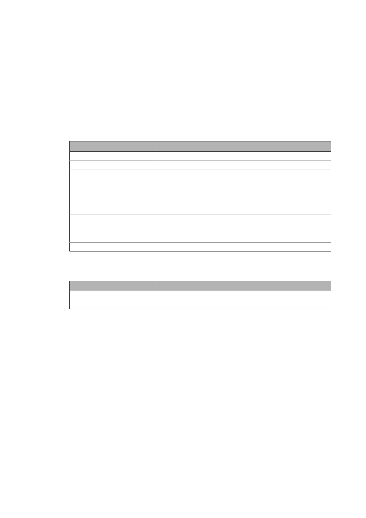
Document history
Version Description
4.2 12/2013 TD23 Revision for DSD version 4.1
4.1 07/2013 TD23 Revision for DSD version 4.0
4.0 02/2013 TD23 Partly revised for DSD version 4.0
3.1 01/2012 TD23 Descriptions for multi-axis application, structure of the drive axis, DC bus, energy ef-
3.0 02/2011 TD23 Revision for DSD version 3.0
ficiency, warning signals extended; errors corrected.
14 Lenze · Drive Solution Designer · Manual · DMS 4.2 EN · 12/2013 · TD23
Page 15

2 About this documentation
2.1 Structure of the documentation
_ _ _ _ _ _ _ _ _ _ _ _ _ _ _ _ _ _ _ _ _ _ _ _ _ _ _ _ _ _ _ _ _ _ _ _ _ _ _ _ _ _ _ _ _ _ _ _ _ _ _ _ _ _ _ _ _ _ _ _ _ _ _ _
2.1 Structure of the documentation
•In the chapter "User interface" you get to know the user interface of the »Drive Solution Design-
er«.
( 18)
•In the chapter "Setting up the DSD workplace
of the DSD.
( 41)
" it is described how you change the basic settings
•In the chapter "Drive dimensioning tools
are described.
( 55)
• In the chapter "Managing projects
• In the chapter "Applications
calculations.
( 65)
• In the chapter "Motion design
" the applications provided in the DSD are described with detailed
" the different motion profiles are described. ( 224)
• In the chapter "Mains and environment
scribed.
( 277)
• In the chapter "Structure of the drive axis
define the mechanical and electrical drive axis and the drive concept.
• In the chapter "Drive Dimensioning
nents are described.
( 308)
• In the chapter "Components in the DC bus
the auxiliary multi-axis calculator are described.
•The "Drive dimensioning messages
during the configuration of the application.
• In the chapter "Auxiliary means
" you are provided with information on the auxiliary calculators
and value tables integrated in the DSD.
• In the chapter "Details on Lenze products
• In the chapter "Restrictions of the drive dimensioning
" the required preparations for the project to be created
" the actual work on a DSD project is described. ( 52)
" the electrical supply systems for the drive are de-
" you are provided with comprehensive information to
( 282)
" the parameters for dimensioning the individual compo-
" the components in the DC bus and the function of
( 361)
" chapter describes messages, notes and tips which can occur
( 441)
( 401)
" options for Lenze products are described. ( 377)
" the operating modes & scenarios that
are not checked or only checked to a limited extent by the DSD are described.
• In the chapter "Results: comparing, optimising, logging
the DSD are described.
•In the chapter "Feedback, help & support
( 385)
", among other things, you are provided with informa-
tion on the acquisition of application data integrated in the DSD.
" the different result presentations of
( 484)
( 426)
Lenze · Drive Solution Designer · Manual · DMS 4.2 EN · 12/2013 · TD23 15
Page 16

2 About this documentation
2.2 Conventions used
_ _ _ _ _ _ _ _ _ _ _ _ _ _ _ _ _ _ _ _ _ _ _ _ _ _ _ _ _ _ _ _ _ _ _ _ _ _ _ _ _ _ _ _ _ _ _ _ _ _ _ _ _ _ _ _ _ _ _ _ _ _ _ _
2.2 Conventions used
This documentation uses the following conventions to distinguish the following types of information:
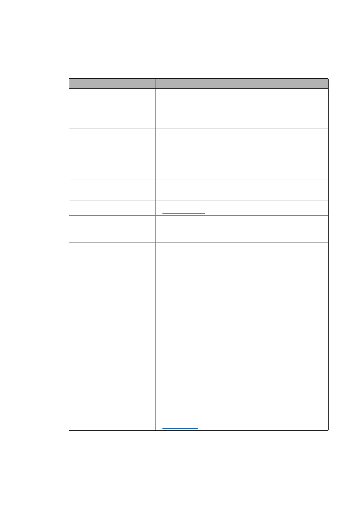
Type of information Marking Examples/notes
Spelling of numbers
Decimal separator Point The decimal point is generally used.
For example: 1234.56
Text
Version info Blue text colour Information that is only valid for or as from a certain soft-
Program name » « The Lenze PC software »PLC Designer«...
Window area Italics The Message window... / The Options dialog box...
Variable identifiers By setting bEnable to TRUE...
Control element Bold The OKbutton... / The Copy command ... / The Properties
Sequence of menu commands
Keyboard command <Bold> By <F1>, you call up the online help.
Program code Courier
Keyword Courier bold
ware version of the controller is marked accordingly in this
documentation.
Example: The function extension is available from software
version V3.0 or higher!
tab... / The Name input field ...
If several commands in succession are required to carry out a
function, the individual commands are separated by an arrow: select the command File
If a keyboard combination is required for a command, a "+" is
placed between the keyboard identifiers: by <Shift>+<ESC>...
IF var1 < var2 THEN
a = a + 1
END IF
Open to...
Hyperlink underlined
Icons
Page reference ( 16) Optically highlighted reference to another page which is ac-
Step-by-step instruction
Optically highlighted reference to another topic which is activated via mouse-click in this online documentation.
tivated via mouse-click in this online documentation.
Step-by-step instructions are indicated by a pictograph.
16
Lenze · Drive Solution Designer · Manual · DMS 4.2 EN · 12/2013 · TD23
Page 17

2 About this documentation
2.3 Definition of the notes used
_ _ _ _ _ _ _ _ _ _ _ _ _ _ _ _ _ _ _ _ _ _ _ _ _ _ _ _ _ _ _ _ _ _ _ _ _ _ _ _ _ _ _ _ _ _ _ _ _ _ _ _ _ _ _ _ _ _ _ _ _ _ _ _
2.3 Definition of the notes used
In order to indicate dangers and important information, the following signal words and symbols are
used:
Safety information
Layout of the safety instructions:
Pictograph and signal word!
(indicate the type and the degree of the danger)
Note
(describes the danger and provides information on its prevention)
Pictograph Signal word Meaning
Danger! Danger of injuries to persons by hazardous electrical voltage
Danger! Danger of personal injury by a general source of danger
Stop! Danger of damage to material assets
Application notes
Note with regard to an imminent danger, which may result in death or severe injuries if the appropriate measures are not taken.
Note with regard to an imminent danger, which may result in death or severe injuries if the appropriate measures are not taken.
Note with regard to a possible danger which ma y result in damage to material assets
if the appropriate measures are not taken.
Pictograph Signal word Meaning
Note! Important note for the trouble-free function
Tip! Useful tip for simple handling
Specific safety instructions and application notes for UL and UR
Pictograph Signal word Meaning
Warnings! Safety instruction or application note for the operation of a UL approved drive in UL
Warnings! Safety instruction or application note for the operation of a UR approved drive in UL
approved systems
Possibly the drive system is not operated in a UL approved manner, if the appropriate
measures are not taken.
approved systems
Possibly the drive system is not operated in a UL approved manner, if the appropriate
measures are not taken.
Lenze · Drive Solution Designer · Manual · DMS 4.2 EN · 12/2013 · TD23 17
Page 18
3User interface
3.1 Control and function elements
_ _ _ _ _ _ _ _ _ _ _ _ _ _ _ _ _ _ _ _ _ _ _ _ _ _ _ _ _ _ _ _ _ _ _ _ _ _ _ _ _ _ _ _ _ _ _ _ _ _ _ _ _ _ _ _ _ _ _ _ _ _ _ _
3 User interface
This chapter introduces different control and function elements of the user interface to you and explains how you can close the program again.
Control and function elements
Shortcuts
( 39)
Closing the program
( 40)
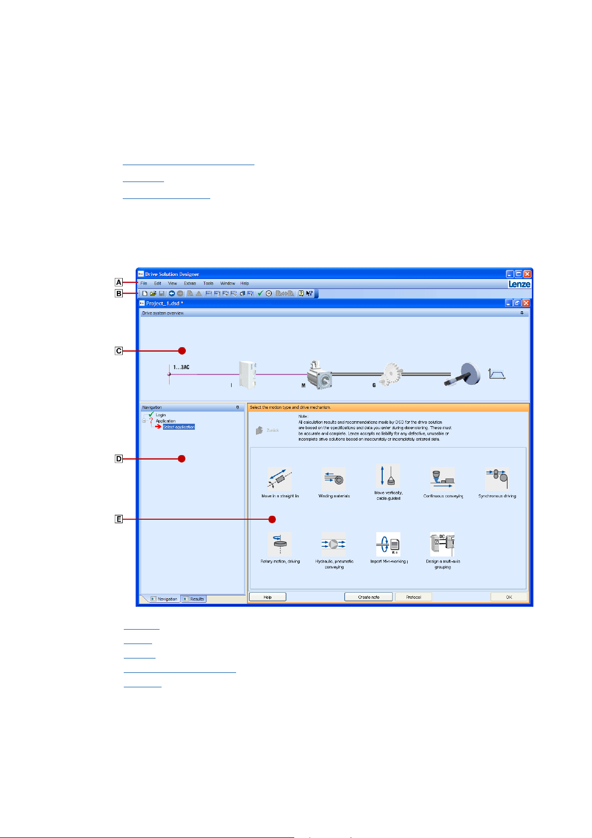
3.1 Control and function elements
The user interface has the following control and function elements:
18
Menu bar ( 19)
Toolbar
Drawing
Navigation tree and result tree
Input area
( 24)
( 27)
( 33)
( 32)
Lenze · Drive Solution Designer · Manual · DMS 4.2 EN · 12/2013 · TD23
Page 19
3User interface
3.1 Control and function elements
_ _ _ _ _ _ _ _ _ _ _ _ _ _ _ _ _ _ _ _ _ _ _ _ _ _ _ _ _ _ _ _ _ _ _ _ _ _ _ _ _ _ _ _ _ _ _ _ _ _ _ _ _ _ _ _ _ _ _ _ _ _ _ _
3.1.1 Menu bar
Via the Menu bar you have access to all menu commands.
• Click a menu to show the contained menu commands.
• Click a menu command to execute the connected function.
• Grey menu commands are inactive during the current program state.
3.1.1.1 File
Menu command Function
New Create new project
Open Open project
Open last project A list of the last five projects edited is provided
Close project Close the open project.
Saving Saving the project
• The current dimensioning state is saved in a project file.
• If the project file is already existing, it is overwritten by the current dimensioning status.
Save as... Save the current dimensioning status as a project with the specified name.
• If the project name is different from the project that may currently be edited, it is renamed.
• The project name is displayed in the window headline.
Exit Closing the program
( 52)
( 54)
( 54)
( 40)
3.1.1.2 Edit
Menu command Function
Move one step back Move one entry back in the navigation tree.
Move one step forward Move one entry forward in the navigation tree.
Lenze · Drive Solution Designer · Manual · DMS 4.2 EN · 12/2013 · TD23 19
Page 20

3User interface
3.1 Control and function elements
_ _ _ _ _ _ _ _ _ _ _ _ _ _ _ _ _ _ _ _ _ _ _ _ _ _ _ _ _ _ _ _ _ _ _ _ _ _ _ _ _ _ _ _ _ _ _ _ _ _ _ _ _ _ _ _ _ _ _ _ _ _ _ _
3.1.1.3 View
Menu command Function
Notes • Note recording current dimensioning step
• Display or write a comment on the current dimensioning step.
• All notes
• Display, print or deletion of all comments that were created for the
project.
Notes
( 37)
Messages Shows all warnings, notes and tips for the current drive dimensioning.
Drive dimensioning messages
Dimensioning report Create and display Protocol.
• The dimensioning protocol that is generated can be printed or opened in
Microsoft Word.
• The completeness of the report depends on the progress of the dimensioning. If the dimensioning report is opened early, some components
possibly are not displayed.
• At the end of the drive dimensioning the DSD offers different possibilities
of presenting the results.
Protocols
Project comparison Compare projects among each other.
• If several projects are open at the same time, they can be compared with
respect to the application and the utilisation of the components.
Protocols
Product features for DSC / SAP Shows product features of the components which are required for the pur-
chase order with »Drive Solution Catalogue« (DSC). DSC is the electronic catalogue on the Lenze web page.
( 391)
( 391)
( 441)
3.1.1.4 Extras
Menu command Function
User-defined defaults Display/definition of user-defined specifications.
• User-defined specifications can be established for specific parameters requiring manual entries or featuring an option.
Select language Change the language of the user interface.
• German, English (British), Czech, Danish, English (American), Spanish,
French, Italian, Dutch, Russian, Swedish, Chinese (simplified) and Chinese
(traditional) are provided.
Settings Settings
( 46)
20
Lenze · Drive Solution Designer · Manual · DMS 4.2 EN · 12/2013 · TD23
Page 21
3User interface
3.1 Control and function elements
_ _ _ _ _ _ _ _ _ _ _ _ _ _ _ _ _ _ _ _ _ _ _ _ _ _ _ _ _ _ _ _ _ _ _ _ _ _ _ _ _ _ _ _ _ _ _ _ _ _ _ _ _ _ _ _ _ _ _ _ _ _ _ _
3.1.1.5 Tools
Menu command Function
Checklist Display check list.
• Every application provides a check list including requests for the respective application.
• Parameters indicated with * have to be known for the dimensioning.
• The calculability at least requires the *parameters of the process and of
the motion; all further requests concerning components are optional.
Calculator Calculator (Microsoft® calculator)
Inertial calculator Calculation of moments of inertia on the basis of geometric quantities and
Mass calculator Calculation of masses on the basis of geometric quantities and the material-
MotionDesigner Irrespective of the dimensioning of a project, motion profiles can be created,
Gearbox calculator Conversion of gearbox sizes.
Energy efficiency, fan/pump Host computer to detect energy savings for applications with pumps or fans.
Special host computers Determination of specific parameters of an application. The following auxil-
Physical coefficients Value tables with physical coefficients. The tables can also be called in aux-
the material-specific density.
Inertial calculator
specific density.
Mass calculator
loaded, edited, and saved graphically or manually.
MotionDesigner
Gearbox calculator
• Comparison of an electronic control (frequency inverter) with a lossy mechanical control. The system parameters and the frequency distribution
of the load are defined.
iary calculators are included in the DSD:
• Travelling resistance
• Pinion diameter
• Spindle efficiency
• Mass of belt
• Mass of delivery volume (materials handling technology)
• Uniform load mass (materials handling technology)
•Backing force
• Mass of counterweight (hoist drive)
• Mass of rope/cable (hoist drive)
Special host computers
iliary calculators and input templates. Like this the coefficients can be accepted directly in the input field. The following value tables are included in
the DSD:
• Density of solids
• Density of winding material
• Density of liquids
• Static friction coefficient
• Sliding friction coefficient
• Coefficient of friction for rolls
• Bearing and leadscrew friction
• Wheel flange and lateral friction
• Lever arm of rolling friction
• Shunt-force factor for belt conveyors
• Filling factor for belt conveyors
• Efficiency of drive elements
Tables of values
( 407)
( 405)
( 225)
( 410)
( 403)
( 423)
( 404)
Lenze · Drive Solution Designer · Manual · DMS 4.2 EN · 12/2013 · TD23 21
Page 22

3User interface
3.1 Control and function elements
_ _ _ _ _ _ _ _ _ _ _ _ _ _ _ _ _ _ _ _ _ _ _ _ _ _ _ _ _ _ _ _ _ _ _ _ _ _ _ _ _ _ _ _ _ _ _ _ _ _ _ _ _ _ _ _ _ _ _ _ _ _ _ _
Menu command Function
Collection of formulae "Drive solutions – formulae, tables and dimensioning" Manual in the PDF
Other tools (web links) Useful references to the Lenze web page. For using it, an internet connection
3.1.1.6 Window
format.
• The reference book, formulary and tables provide the physical-mathematical basics in drive technology.
• The Manual can be read e.g. with the free-of-charge Adobe Reader.
is required.
• Drive Solution Catalogue (DSC)
• Electronic catalogue to configure and/or order drive components and
accessories.
• Sales documents, technical documentation, software
• Generation of CAD data
• CAD data of Lenze motors
• EPLAN macros for Lenze products
• Generation of torque characteristics
• Check Overload capacity of motor/inverter combinations
In the Window menu, all open DSD projects are listed. By selecting the corresponding menu item
the project window is shown in the front. Project windows can be arranged using the following
menu commands:
Menu command Function
Cascading window If several windows are open, they are arranged one behind the other in a
Split window horizontally The display window is split horizontally into several areas. The projects are
slightly staggered manner; by this other windows can be quickly selected.
arranged one below the other.
22
Lenze · Drive Solution Designer · Manual · DMS 4.2 EN · 12/2013 · TD23
Page 23

3User interface
3.1 Control and function elements
_ _ _ _ _ _ _ _ _ _ _ _ _ _ _ _ _ _ _ _ _ _ _ _ _ _ _ _ _ _ _ _ _ _ _ _ _ _ _ _ _ _ _ _ _ _ _ _ _ _ _ _ _ _ _ _ _ _ _ _ _ _ _ _
3.1.1.7 Help
Menu command Function
About DSD Open the information dialog showing the version number, registration in-
Help Open online help.
Dimensioning examples Examples of different drive dimensionings.
Check for updates Search for available updates for the DSD.
Acquisition of application data Send log file with application information to the Lenze DSD server.
Support on the Web (AKB) Weblink to the Lenze Application Knowledge Base.
Search AKB Search the Lenze Application Knowledge Base for information and solutions.
Version information (AKB) Search the Lenze Application Knowledge Base for up-to-date information
Subscribe to the AKB newsletter Automatic e-mail notification when new issues in the Lenze Application
Software downloads The download area of the Lenze Application Knowledge Base contains the
Lenze on the Internet The Lenze webpage contains current information on the company and its
formation, and important information about DSD.
• The DSD files can be used as a template for individual drive dimensionings.
• For using it, an internet connection is required.
• The log file contains important information on the Lenze development
for optimising the Drive Solution Designer.
• For using it, an internet connection is required.
Acquisition of application data
• The Application Knowledge Base contains various information on the
Drive Solution Designer.
• For using it, an internet connection is required.
• For using it, an internet connection is required.
and solutions about DSD.
•Under SoftwareDrive Solution Designer, e.g. Release Notes or notes re-
garding functional restrictions can be found.
• For using it, an internet connection is required.
Knowledge Base are released.
• For using it, an internet connection is required.
current DSD version and the published service packages.
• Always use the most current service package!
• For using it, an internet connection is required.
products.
• For using it, an internet connection is required.
http://www.Lenze.com
( 484)
Lenze · Drive Solution Designer · Manual · DMS 4.2 EN · 12/2013 · TD23 23
Page 24
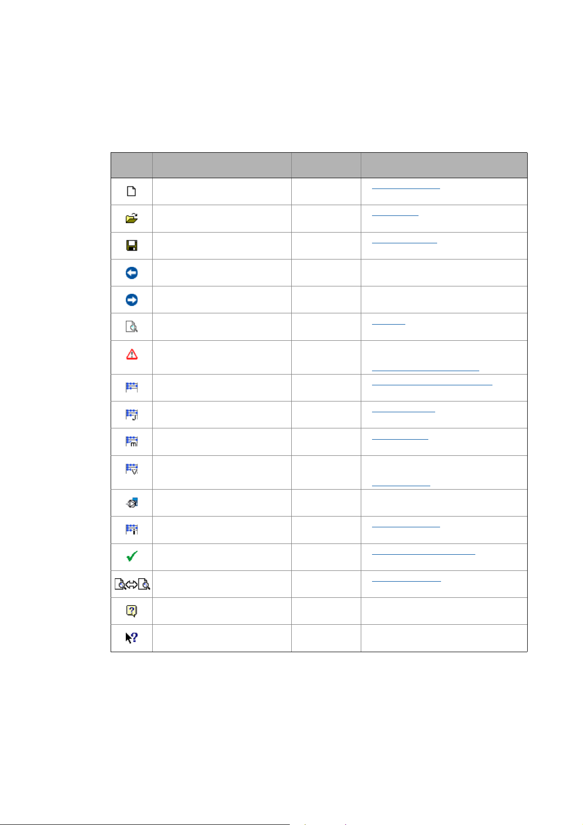
3User interface
3.1 Control and function elements
_ _ _ _ _ _ _ _ _ _ _ _ _ _ _ _ _ _ _ _ _ _ _ _ _ _ _ _ _ _ _ _ _ _ _ _ _ _ _ _ _ _ _ _ _ _ _ _ _ _ _ _ _ _ _ _ _ _ _ _ _ _ _ _
3.1.2 Toolbar
Via the icons in the toolbar you can directly carry out the most frequently used functions.
• Click on an icon to carry out the respective function.
Symbol Menu command Keyboard com-
File
New
Open...
File
Save
File
Undo
Edit
Redo
Edit
View
Dimensioning report...
Warning signals...
View
Calculator...
Tools
Inertial calculator...
Tools
mand
<Ctrl>+<N> Create new project
<Ctrl>+<O> Open project
<Ctrl>+<S> Saving the project
– Undo last action
– Redo last undone action
– Protocols
– Shows all warning signals, notes and tips for
– Calculator (Microsoft® calculator)
<Alt+T> Inertial calculator
Function
( 52)
( 54)
( 54)
( 391)
the current drive dimensioning.
Drive dimensioning messages
( 407)
( 441)
( 404)
Mass calculator...
Tools
<Alt+M> Mass calculator
( 405)
MotionDesigner...
Tools
ToolsEnergy-efficient fan/pump...
Tools
Gearbox calculator...
Application checklist...
Tools
Project comparison...
View
Help
Help
––Call up context-sensitive help
– Creating, changing and saving motion pro-
– Detecting energy efficiency for applications
<Alt+G> Gearbox calculator
– Data collection via checklists
– Project comparison
<F1> Call up help
files
MotionDesigner
with fans or pumps
( 225)
( 410)
( 61)
( 55)
24
Lenze · Drive Solution Designer · Manual · DMS 4.2 EN · 12/2013 · TD23
Page 25
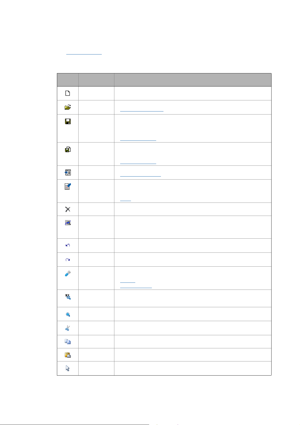
3User interface
3.1 Control and function elements
_ _ _ _ _ _ _ _ _ _ _ _ _ _ _ _ _ _ _ _ _ _ _ _ _ _ _ _ _ _ _ _ _ _ _ _ _ _ _ _ _ _ _ _ _ _ _ _ _ _ _ _ _ _ _ _ _ _ _ _ _ _ _ _
The MotionDesigner
serves to carry out the most frequently required functions via the icons in the
toolbar. Many functions can also be carried out via shortcuts. There are no menu commands.
• Click on an icon to carry out the respective function.
Symbol Keyboard com-
mand
<Ctrl>+<N> Create new motion profile.
<Ctrl>+<O> Load motion profile.
<Ctrl>+<S> Save motion profile.
– Save motion profile as...
– Import the motion profile with parameter profiles from an ASCII file.
– Create note for motion profile
<Del> Delete highlighted element.
– Application analysis.
<Ctrl>+<Z> Undo last action.
Function
Load the motion profile
• When a newly created motion profile is saved, you are asked for the destination
of the Imp file.
• When the motion profile is newly saved, the Imp file is updated.
Save motion profile
• During the saving process, you are asked for the destination of the Imp file.
•
Save motion profile
Importing profile data
• The note is attached to the "Motion" dimensioning step.
• The function is only available with the application-dependent MotionDesigner.
Notes
( 37)
• The element is deleted permanently.
• Shows diagrams and table of values via the entered and calculated values with
regard to a cycle of the motion profile.
• The function is only available with the application-dependent MotionDesigner.
( 234)
( 235)
( 235)
( 236)
( 225)
<Ctrl>+<Y> Redo last undone action.
– Default settings for the dialog box.
• Identical to the "Motion" register in the DSD menu ExtrasSettings.
Settings
"Motion" register
– Zoom x-axis and y-axis
• Draw up a rectangle across the area to be zoomed in by keeping the left mouse
– Return to standard view.
<Ctrl>+<X> Cut the highlighted element and drag to the clipboard.
<Ctrl>+<C> Copy the highlighted element into the clipboard.
<Ctrl>+<V> Paste the element from the clipboard.
– Select the element or deactivate an active symbol.
( 46)
( 48)
button pressed.
Lenze · Drive Solution Designer · Manual · DMS 4.2 EN · 12/2013 · TD23 25
Page 26
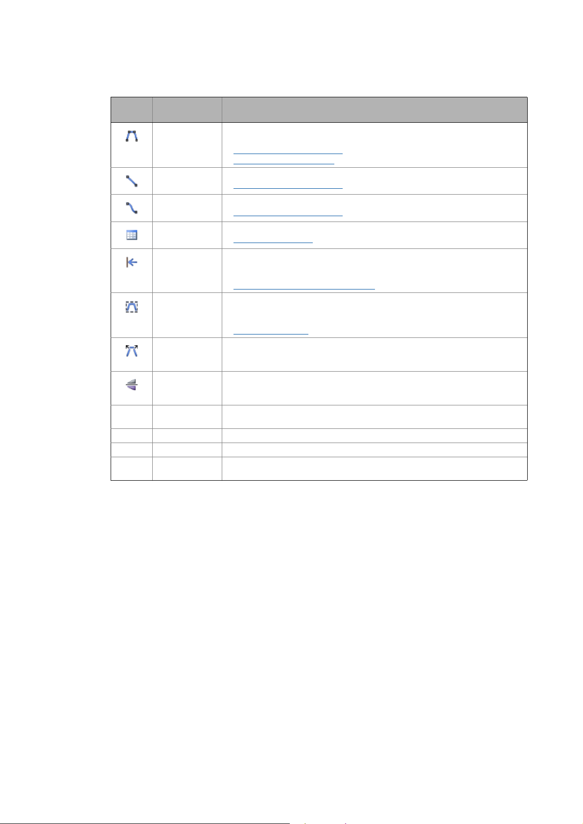
3User interface
3.1 Control and function elements
_ _ _ _ _ _ _ _ _ _ _ _ _ _ _ _ _ _ _ _ _ _ _ _ _ _ _ _ _ _ _ _ _ _ _ _ _ _ _ _ _ _ _ _ _ _ _ _ _ _ _ _ _ _ _ _ _ _ _ _ _ _ _ _
Symbol Keyboard com-
mand
– Draw trapezoidal element.
– Draw line.
– Draw S-shaped element.
– Import an individual motion profile or parameter profile.
– Move elements to the left.
– Combines the elements that form a trapezium so that an element is generated.
– Undo combination.
– Reflect highlighted element on the time axis.
– <Ctrl>+<Click> Duplicates an element in the drawing area when the element is right-clicked while
– <Ctrl>+<G> Shows or hides the grid of the drawing area.
– <Ctrl>+<A> Highlights all elements on the drawing area.
– <Shift>+<Click> In order to highlight several elements keep the <Shift> button pressed and right-
Function
• The "Profile" register contains a selection of trapezoidal elements.
Creating and editing elements
Parameter area: Description
Creating and editing elements
Creating and editing elements
Importing profile data
• Moves separated elements on the drawing area to the left and connects them to
its preceding element.
Shift elements automatically to the left
• Only connected elements can be combined.
• The elements to be combined must be highlighted.
Combining elements
• Deactivate the combination of a trapezoidal element so that the elements can be
processed separately.
• This function can only be accessed via the context menu (click the right mouse
button).
the Ctrl key is pressed.
click the elements.
( 236)
( 245)
( 242)
( 247)
( 242)
( 242)
( 244)
26
Lenze · Drive Solution Designer · Manual · DMS 4.2 EN · 12/2013 · TD23
Page 27
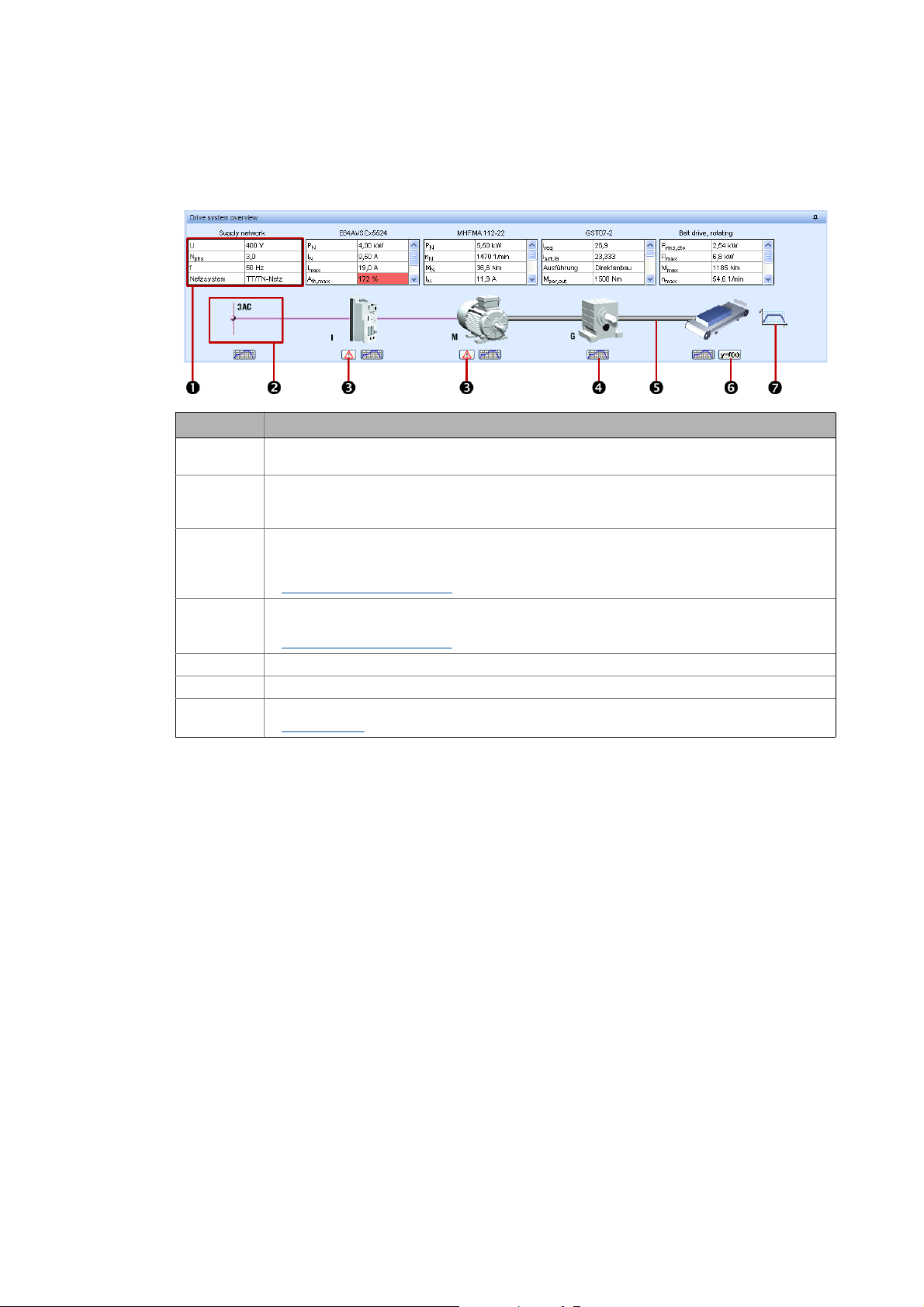
3User interface
3.1 Control and function elements
_ _ _ _ _ _ _ _ _ _ _ _ _ _ _ _ _ _ _ _ _ _ _ _ _ _ _ _ _ _ _ _ _ _ _ _ _ _ _ _ _ _ _ _ _ _ _ _ _ _ _ _ _ _ _ _ _ _ _ _ _ _ _ _
3.1.3 Drawing
The drawing visualises the current state of the drive dimensioning.
Legend Information
Short overview of the drive system with the data entered, rated data of the selected drive compo-
Illustration of the component (at the same time button).
Button for calling messages and notes for the corresponding component.
Button for calling the diagrams for the corresponding component.
Representation of the drive train used.
Button for calling the description of the application in the online help.
Button for calling the motion profile.
nents and their utilisation, and display of warning parameters.
• By clicking on the illustration you directly reach the selection table for the corresponding component where a variety of data is provided.
• Disregarding warning signals may result in damage or malfunctions of the application, as far as
this is not monitored by the system.
Drive dimensioning messages
• Graphical representation of the speed, torque and utilisation behaviour.
Diagrams for the components
Motion design
( 224)
( 441)
( 387)
Notes
• At the beginning of the configuration a general drive train is displayed, consisting of the following components:
• Mains/environment
•Inverters
• Motor
•Gearbox
• Application
•Motion
• The components inverter and gearbox (with or without an additional drive element) are optional, i. e. their existence depends on the application or the dimensioning procedure.
• Therefore these components are displayed in an inactive manner at the beginning of the dimensioning. Depending on the further procedure the inverter or gearbox is displayed or removed from the drawing.
• Additionally, with regard to multi-axis applications, the drawing can be extended by a power
supply module (Master project) or by a place holder (Slave project).
• If an "Additional drive element" is used, this is symbolised by a toothed belt in the drawing, irrespective of the type selected.
Lenze · Drive Solution Designer · Manual · DMS 4.2 EN · 12/2013 · TD23 27
Page 28

3User interface
3.1 Control and function elements
_ _ _ _ _ _ _ _ _ _ _ _ _ _ _ _ _ _ _ _ _ _ _ _ _ _ _ _ _ _ _ _ _ _ _ _ _ _ _ _ _ _ _ _ _ _ _ _ _ _ _ _ _ _ _ _ _ _ _ _ _ _ _ _
• The drawing shows additional information required for a dimensioning process.
• Above the images of the components, important parameters and their values are shown in
tables.
• Below the images of the components, depending on the dimensioning a button is displayed,
via which you can call the diagrams for the component.
3.1.3.1 "Application" image
Symbol Description
a
max
d
dim
HW Winding characteristic (hard/soft), describes the tensile force drop for rewinders as a function
J
max
k
f
k
M
l
max
m
max,L
M
max
Mode Winder control mode
n
av
n
max
P
cto
P
max
P
rms,cto
q
dim
q
max
N(*.dsd) Number of DSD projects
N
D
t
Crd
P
mot,max
P
mot,av
P
gen,av
P
gen,max
Max. acceleration of the application
Dimensioning diameter
• Diameter which is reached after termination of the acceleration phase.
of the reel diameter
Max. moment of inertia of load
Tensile force setting range, KF = F
Torque setting range, kM = M
max(dmax
max/Mmin
Length of the winding material for a max. reel diameter d
)/F
min(dmin
)
and a min. material thickness s
max
Max. mass of the winding material
Required max. torque of the application
• Is determined from the diagram for the torque.
Average speed of the application
Max. speed of the application
• Is determined from the diagram for the speed.
Base process power of the application used for motor dimensioning
• The base process power is a theoretical value resulting from the max. speed and the max.
torque of the application.
• The base process power often equals the max. required power, since the max. speed and the
max. torque are often required at the same time.
Required max. power of the application
• Is determined from the diagram for the power.
Required thermal power of the motor
Dimensioning winding ratio, q
Max. winding ratio, q
max
= d
= d
dim
max/dmin
max/dmin
Number of drive axes with multi-axis system.
Movement of drive axes
• Axes coordinated
• Axes uncoordinated
Coordinated cycle time
Max. occurring motor power
Average power (mean value)
Required average power of the brake resistor, taking into account the thermal time constant.
Max. occurring regenerative power
min
28
Lenze · Drive Solution Designer · Manual · DMS 4.2 EN · 12/2013 · TD23
Page 29

3User interface
3.1 Control and function elements
_ _ _ _ _ _ _ _ _ _ _ _ _ _ _ _ _ _ _ _ _ _ _ _ _ _ _ _ _ _ _ _ _ _ _ _ _ _ _ _ _ _ _ _ _ _ _ _ _ _ _ _ _ _ _ _ _ _ _ _ _ _ _ _
3.1.3.2 "Gearbox" image
Symbol Description
A(M
) Ratio of the equivalent torque to the max. permissible torque:
eq
A(M
A(M
A(n
A
th,1,G(nth
) Clutch utilisation with reference to the max. drive torque
in,max
) Ratio of the max. torque of the application to the max. permissible torque of the gearbox:
max
) Max. occurring speed relative to the max. speed of the gearbox:
max
) Utilisation of the gearbox relative to the thermal output speed
A(T) Utilisation of the gearbox relative to the fatique strength
Design Direct or standard mounting of the motor on the Lenze gearbox
i
req
i
2,req
i
act,G
i
act,K
J
out,K
k
G
M
per,out
M
eq
η
K
n
in,max
n
out,max
n
per,in,max
n
per,th,out
M
/ M
eq
max,per,G
• For flange mounting only
M
/ M
max
max,per,G
n
/ n
max
max,G
• If the value is > 100 %, an exact check is required.
Required ratio (Lenze gearbox and additional drive element if required)
• Is calculated from the intended input speed of the gearbox, relative to the max. speed of the
application:
n
in/nmax
•Ratio i
is required to operate the motor with the field weakening factor specified by DSD.
req
Required ratio of the additional drive element under consideration of a Lenze gearbox, if any
• Is calculated from the intended input speed, relative to the max. speed of the application:
n
in/nmax
•Ratio i
is required to operate the motor with the field weakening factor specified by DSD.
req
Actual ratio of the Lenze gearbox
Actual ratio of the additional drive element
Moment of inertia at the output end of the additional drive element
Correction factor for the torque of the gearbox
Permissible output torque without speed evaluation.
Equivalent output torque of the Lenze gearbox
• Is calculated from the diagram for the torque of the application.
Efficiency of the additional drive element at the rated point
Max. input speed of the Lenze gearbox
• Is determined from the M-n diagram of the Lenze gearbox
Max. speed at the output shaft
Max. permissible input speed of the Lenze gearbox
Permissible thermal output speed of the gearbox
Lenze · Drive Solution Designer · Manual · DMS 4.2 EN · 12/2013 · TD23 29
Page 30

3User interface
3.1 Control and function elements
_ _ _ _ _ _ _ _ _ _ _ _ _ _ _ _ _ _ _ _ _ _ _ _ _ _ _ _ _ _ _ _ _ _ _ _ _ _ _ _ _ _ _ _ _ _ _ _ _ _ _ _ _ _ _ _ _ _ _ _ _ _ _ _
3.1.3.3 "Motor" image
Symbol Description
P
N
n
rated
M
rated
I
N
A
th,max
A(M
) Utilisation of the motor relative to the torque
max
A(M
) Utilisation of the motor with reference to the effective torque and taking into account the ther-
rms
A(M
k
k
) Dynamic utilisation of the motor
dyn,M
f
J,max
Rated power of the motor
Rated speed of the motor
Rated torque of the motor
Rated motor current
Max. thermal utilisation of the motor
• Ratio of the max. required torque to the max. possible torque of the motor during operation
on the selected inverter and with the selected control mode:
max,req
/ M
max,M
M
mal time constant
• Ratio of the max. occurring motor torque to the rated motor torque:
(M
/ MN)
max
Field weakening factor of the motor
Load-matching factor of the motor
3.1.3.4 "Inverter" image
Symbol Description
A(I
/ I
max
rated,M
A(I
A(I
A
th,Brm
A
Brm
A
max
A
th
A
th,max
I
max
I
N
P
N
Type Type of brake resistor
) Thermal utilisation of the inverter relative to the power pulse current for 1 s or 60 s
imp,max
) Utilisation of the inverter relative to the reduced max. output current
red,max
(ED) Utilisation of the internal brake transistor, relative to the i×t monitoring
) Utilisation of the inverter
• Ratio of the max. output current of the inverter (I
) to the rated motor current (I
max
• If the inverter is highly overdimensioned with regard to the motor, the control quality de-
creases.
Thermal utilisation of the internal brake transistor
Max. utilisation of the brake resistor
Thermal utilisation of the brake resistor
Max. thermal utilisation of the inverter relative to the reduced output current
Max. output current of the inverter selected
Rated current of the inverter selected
Rated motor power of the inverter selected
N,M
).
30
Lenze · Drive Solution Designer · Manual · DMS 4.2 EN · 12/2013 · TD23
Page 31

3User interface
3.1 Control and function elements
_ _ _ _ _ _ _ _ _ _ _ _ _ _ _ _ _ _ _ _ _ _ _ _ _ _ _ _ _ _ _ _ _ _ _ _ _ _ _ _ _ _ _ _ _ _ _ _ _ _ _ _ _ _ _ _ _ _ _ _ _ _ _ _
3.1.3.5 Image "Power supply module" or "Regenerative power supply module"
Symbol Description
A
(ED) Utilisation of the internal brake transistor, relative to the i×t monitoring
Brm
A
Brm(Pmax
A
max,Rb
A
Sup(Pimp,DC
A
Sup(Pmax
A
Sup(Pgen,max
A
Sup,Brm(Pgen,max
A
th,Brm
A
th,Rb
A
th,Sup
P
gen,cto
P
gen,max
P
gen,N
P
max(τ1
P
max(τ2
P
rated
Type Type of brake resistor
) Utilisation of the brake transistor, relative to the max. power
Max. utilisation of the brake resistor
) Utilisation of the power supply module, relative to the pulse power in the DC bus.
) Utilisation of the power supply module, relative to the max. power.
) Utilisation of the regenerative power supply module without brake transistor, relative to the
max. regenerative power
) Utilisation of the regenerative power supply module with brake transistor, relative to the max.
regenerative power
Thermal utilisation of the brake transistor
Thermal utilisation of the brake resistor
Thermal utilisation of the power supply module
Regenerative power from which a brake resistor is used additionally
Max. permissible regenerative power
Rated power in generator mode
) Max. permissible power, relative to the 5-s cycle
• 0.5 s overload / 4.5 s load removal with 75 % of the continuous rated quantity
) Max. permissible power, relative to the 3-s cycle
• 60 s overload / 120 s load removal with 75 % of the continuous rated quantity
Rated power
3.1.3.6 "Supply network" image
The displayed quantities always refer to the supplying mains (AC mains or DC mains). In case of multi-axis controllers that are connected via a power supply module or a regenerative power supply
module, the values of the power supply unit are indicated.
Symbol Description
U Rated mains voltage of the supplying electrical network
N
phs
f Mains frequency of the supplying electrical network
Power system Power system of the supplying three-phase system
Number of phases of the supplying electrical network
Lenze · Drive Solution Designer · Manual · DMS 4.2 EN · 12/2013 · TD23 31
Page 32

3User interface
3.1 Control and function elements
_ _ _ _ _ _ _ _ _ _ _ _ _ _ _ _ _ _ _ _ _ _ _ _ _ _ _ _ _ _ _ _ _ _ _ _ _ _ _ _ _ _ _ _ _ _ _ _ _ _ _ _ _ _ _ _ _ _ _ _ _ _ _ _
3.1.4 Navigation tree and result tree
Below the drawing on the left the Navigation tree or the Result tree is displayed.
• Via the two registers below the Navigation tree or Result tree you can switch between the two
views anytime.
3.1.4.1 Navigation tree
The Navigation tree indicates your position within the dimensioning process:
• A green tick indicates all the dimensioning steps that have been edited.
• The steps still to be edited are indicated by a question mark.
• The current step is marked by a red arrow.
• The context menu (select dimensioning step and click the right mouse button) serves to execute
the following commands:
• Creating an alternative
• Create note and delete note.Notes
• The dimensioning steps marked with contain notes.
• A mouse-click on the icon opens the note.
( 57)
( 37)
Tip!
In the Navigation tree you can also select dimensioning steps that have been previously edited and change to the corresponding input template.
32
Lenze · Drive Solution Designer · Manual · DMS 4.2 EN · 12/2013 · TD23
Page 33

3User interface
3.1 Control and function elements
_ _ _ _ _ _ _ _ _ _ _ _ _ _ _ _ _ _ _ _ _ _ _ _ _ _ _ _ _ _ _ _ _ _ _ _ _ _ _ _ _ _ _ _ _ _ _ _ _ _ _ _ _ _ _ _ _ _ _ _ _ _ _ _
3.1.4.2 Result tree
The Result tree shows the logic structure of the drive train.
• All components of a drive train are visualised with regard to their interconnection via the Result
tree.
• If a component is not clearly selected yet, e.g. if three different motors are still possible, the value range of the parameter is displayed.
Legend Information
Representation in table form of quantities of the application and of rated quantities and calculated
Diagrams of entered and calculated values as well as rated quantities for evaluating the drive task
3.1.5 Input area
In the input area, you enter the parameters for drive dimensioning.
• A dimensioning process is dynamically: depending on the selection made in a dimensioning
step, it may change.
• The representation of the input area depends on the dimensioning step.
• Depending on the task, the input fields, selection fields, the MotionDesigner, selection tables
appear with or without curve diagrams and decision fields.
values of the components.
(application), components and energy efficiency.
Lenze · Drive Solution Designer · Manual · DMS 4.2 EN · 12/2013 · TD23 33
Page 34

3User interface
3.1 Control and function elements
_ _ _ _ _ _ _ _ _ _ _ _ _ _ _ _ _ _ _ _ _ _ _ _ _ _ _ _ _ _ _ _ _ _ _ _ _ _ _ _ _ _ _ _ _ _ _ _ _ _ _ _ _ _ _ _ _ _ _ _ _ _ _ _
3.1.5.1 Structure of the selection tables
Description
Number of results:
• Possible: Total results detected by DSD.
• Visible: Results proposed and displayed by DSD.
Preview value
• A cell with a grey background signalises that the corresponding parameter is a preview value which can
cause a warning signal.
Drive dimensioning messages.
• Several messages can be available for one component.
• The left column always shows the symbol of the highest warning level.
Warning
• Important criteria (e.g. limit values) are not fulfilled. A red background indicates the corresponding value.
Information
• Important information has to be observed for a correct function of the component. A blue background indicates the corresponding value.
Tip
• Tips contain useful information on optimisation. A yellow background indicates the corresponding value.
Button for resetting the extended representation of the selection table.
Button to show more components with smaller performance values.
Show all possible values detected by DSD.
Button to show more components with higher performance values.
34
Lenze · Drive Solution Designer · Manual · DMS 4.2 EN · 12/2013 · TD23
Page 35

3User interface
3.1 Control and function elements
_ _ _ _ _ _ _ _ _ _ _ _ _ _ _ _ _ _ _ _ _ _ _ _ _ _ _ _ _ _ _ _ _ _ _ _ _ _ _ _ _ _ _ _ _ _ _ _ _ _ _ _ _ _ _ _ _ _ _ _ _ _ _ _
3.1.5.2 Sorting and filtering results in selection tables
Sorting results
Sorting by alphanumeric characters is possible. Up to three columns can be included. Table columns
that contain symbols cannot be sorted.
How to sort the results:
1. Click the desired column header .
• The result list is sorted according to the data in the selected table column.
• Sorting of the data sets in ascending order.
• Sorting of the data sets in descending order.
2. Keep the <Ctrl> key pressed and click another column header with the mouse to include an-
other column in the sorting.
Filtering results
• The available filters provide comfortable assistance in selecting specific data sets.
How to filter results:
1. Click the desired button in the header.
• A selection menu opens.
2. Select filter or filter function.
Filter or filter function
Selection menu Description
Display all Reset all filters of the table column.
User-defined When the user-defined filter is selected, a dialog box opens in which three specific filters can
Alphanumeric characters
be set.
Identical value • Select a value to indicate only the data sets with this value.
Value range • Select min. and max. value to indicate only the data sets within
this value range.
Several values • Select several values to indicate only the data sets with these val-
ues.
The selection menu lists all alphanumeric values of the table column.
• Select a value to indicate only the data sets with this value.
Lenze · Drive Solution Designer · Manual · DMS 4.2 EN · 12/2013 · TD23 35
Page 36

3User interface
3.1 Control and function elements
_ _ _ _ _ _ _ _ _ _ _ _ _ _ _ _ _ _ _ _ _ _ _ _ _ _ _ _ _ _ _ _ _ _ _ _ _ _ _ _ _ _ _ _ _ _ _ _ _ _ _ _ _ _ _ _ _ _ _ _ _ _ _ _
3.1.5.3 Changing a value or a selection subsequently
How to change a value or a selection subsequently:
1. Select the desired dimensioning step in the navigation tree.
2. Change the value or the selection in the input area.
3. Press OK.
• You get a confirmation prompt whether the change is to be accepted.
4. Confirm with Yes to accept the change.
• The following, already executed dimensioning steps are deleted.
• The dimensioning process is continued after the changed dimensioning step.
5. Or press No to cancel the executed changes.
36
Lenze · Drive Solution Designer · Manual · DMS 4.2 EN · 12/2013 · TD23
Page 37

3User interface
3.1 Control and function elements
_ _ _ _ _ _ _ _ _ _ _ _ _ _ _ _ _ _ _ _ _ _ _ _ _ _ _ _ _ _ _ _ _ _ _ _ _ _ _ _ _ _ _ _ _ _ _ _ _ _ _ _ _ _ _ _ _ _ _ _ _ _ _ _
3.1.6 Notes
Each dimensioning step can be provided with a notepad for comments and notes. The notes can be
output in the protocol.
How to create a note for a dimensioning step:
1. Select the desired dimensioning step in the navigation tree.
2. Three options to open the Notebad dialog box:
•Open the Context menu with the right mouse button and select Create note.
• Execute the command ViewNotesNote of current dimensioning step.
•Click the Create note button in the status bar.
3. Enter comments and notes.
• A note is created when you at least enter one character.
4. Press the Close button.
• The dimensioning step is marked with .
Lenze · Drive Solution Designer · Manual · DMS 4.2 EN · 12/2013 · TD23 37
Page 38

3User interface
3.1 Control and function elements
_ _ _ _ _ _ _ _ _ _ _ _ _ _ _ _ _ _ _ _ _ _ _ _ _ _ _ _ _ _ _ _ _ _ _ _ _ _ _ _ _ _ _ _ _ _ _ _ _ _ _ _ _ _ _ _ _ _ _ _ _ _ _ _
How to open created notes:
Three options to open a single note:
• Click the desired notepad in the Navigation tree.
•Click the Create note button in the status bar.
• Select the desired dimensioning step in the Navigation tree and execute the command
ViewNotesNote of current dimensioning step.
Open the All notes dialog box:
• Select the desired dimensioning step in the Navigation tree and execute the command
ViewNotesAll notes.
Note!
• You cannot change notes in the dialog box.
• Copying of texts is possible.
• You can print notes via the Print button.
How to delete notes:
A single note:
• Select the desired dimensioning step in the Navigation tree, open the Context menu with
the right mouse button and select Delete note.
All notes:
• Execute the command ViewNotesAll notes.
• Go to the All notes dialog box and press the Delete all button.
•Press OK to close the dialog box.
38
Lenze · Drive Solution Designer · Manual · DMS 4.2 EN · 12/2013 · TD23
Page 39

3User interface
3.2 Shortcuts
_ _ _ _ _ _ _ _ _ _ _ _ _ _ _ _ _ _ _ _ _ _ _ _ _ _ _ _ _ _ _ _ _ _ _ _ _ _ _ _ _ _ _ _ _ _ _ _ _ _ _ _ _ _ _ _ _ _ _ _ _ _ _ _
3.2 Shortcuts
In order to use the DSD easier via keyboard, some functions can be accessed via shortcuts.
Keyboard command Function
<Alt>+<F4> Exit DSD.
<Alt>+<G> Gearbox calculator
<Alt>+<M> Mass calculator
<Alt>+<T> Inertial calculator
<Esc> Cancel current action.
<F1> Call the "Help" menu.
<Ctrl>+<C> Copy the highlighted element into the clipboard.
<Ctrl>+<D> Edit user-defined selections.
<Ctrl>+<N> Create new project
<Ctrl>+<O> Open project
<Ctrl>+<S> Saving the project
<Ctrl>+<V> Paste the element from the clipboard.
• Only numerical values can be entered into input fields.
<Ctrl>+<X> Exit DSD.
<Ctrl>+<Tab> Change between multiple opened projects.
<Tab> Skip to the next control element (input field, button, etc.) within the dialog box.
( 410)
( 405)
( 407)
( 52)
( 54)
( 54)
In order to use the MotionDesigner
cuts.
( 225)
Keyboard command Function
<Del> Delete highlighted element.
• The element is deleted permanently.
<Shift>+<Click> In order to highlight several elements keep the <Shift> button pressed and left-click the el-
<Ctrl>+<A> Highlights all elements on the drawing area.
<Ctrl>+<C> Copy the highlighted element into the clipboard.
<Ctrl>+<G> Shows or hides the grid of the drawing area.
<Ctrl>+<Click> Duplicates an element in the drawing area when the element is left-clicked while the Ctrl
<Ctrl>+<N> Create new motion profile.
<Ctrl>+<O> Load the motion profile
<Ctrl>+<S> Save motion profile
<Ctrl>+<V> Paste the element from the clipboard.
<Ctrl>+<X> Cut the highlighted element and drag to the clipboard.
<Ctrl>+<Y> Redo last undone action.
<Ctrl>+<Z> Undo last action.
ements.
Processing functions
key is pressed.
Processing functions
Processing functions
easier via keyboard, some functions can be accessed via short-
( 229)
( 234)
( 235)
( 229)
( 229)
Lenze · Drive Solution Designer · Manual · DMS 4.2 EN · 12/2013 · TD23 39
Page 40

3User interface
3.3 Closing the program
_ _ _ _ _ _ _ _ _ _ _ _ _ _ _ _ _ _ _ _ _ _ _ _ _ _ _ _ _ _ _ _ _ _ _ _ _ _ _ _ _ _ _ _ _ _ _ _ _ _ _ _ _ _ _ _ _ _ _ _ _ _ _ _
3.3 Closing the program
Options to exit the »Drive Solution Designer«:
• Select the command FileExit.
• Click the Window icon in the Title bar.
• Press the shortcut <CTRL>+<X>.
• Click the shortcut <ALT>+<F4>.
Note!
If the program is closed and projects with changes that are not saved yet are still open,
you are asked via the Save project dialog box whether you want to save the projects.
Managing projects
: Saving the project ( 54)
40
Lenze · Drive Solution Designer · Manual · DMS 4.2 EN · 12/2013 · TD23
Page 41

4 Setting up the DSD workplace
4.1 Settings during installation
_ _ _ _ _ _ _ _ _ _ _ _ _ _ _ _ _ _ _ _ _ _ _ _ _ _ _ _ _ _ _ _ _ _ _ _ _ _ _ _ _ _ _ _ _ _ _ _ _ _ _ _ _ _ _ _ _ _ _ _ _ _ _ _
4 Setting up the DSD workplace
Before starting the work with the »Drive Solution Designer«, please set up your DSD workplace first.
4.1 Settings during installation
During the installation of the DSD, country-specific settings can be changed already:
Select language
• Language of the user interface.
Language selection for the online help
Select the language in which a web link is to be called
• DSD menus Tools and Help contain web links which serve to directly access information provided on the Lenze web page or the Lenze Intranet.
Preferred unit system
• When values are entered, DSD offers the preferred unit system first.
Tip!
The settings can also be changed later in DSD in the menu ExtrasSettings.
Lenze · Drive Solution Designer · Manual · DMS 4.2 EN · 12/2013 · TD23 41
Page 42

4 Setting up the DSD workplace
4.2 Registering and activating DSD licence
_ _ _ _ _ _ _ _ _ _ _ _ _ _ _ _ _ _ _ _ _ _ _ _ _ _ _ _ _ _ _ _ _ _ _ _ _ _ _ _ _ _ _ _ _ _ _ _ _ _ _ _ _ _ _ _ _ _ _ _ _ _ _ _
4.2 Registering and activating DSD licence
After the installation of the DSD on the computer, your DSD licence must be registered and activated with Lenze.
• Before the activation, install the current service pack.
• Software updates can be found on the Internet:
http://www.Lenze.com
If you start the DSD after the installation, the Registration dialog box will be displayed.
"Downloads" area
Register
Enter the required data in the fields marked with *.
42
Lenze · Drive Solution Designer · Manual · DMS 4.2 EN · 12/2013 · TD23
Page 43

4 Setting up the DSD workplace
4.2 Registering and activating DSD licence
_ _ _ _ _ _ _ _ _ _ _ _ _ _ _ _ _ _ _ _ _ _ _ _ _ _ _ _ _ _ _ _ _ _ _ _ _ _ _ _ _ _ _ _ _ _ _ _ _ _ _ _ _ _ _ _ _ _ _ _ _ _ _ _
Activating the DSD licence automatically
Recommended if a connection to the Internet has been established.
1. Click the Automatic button.
• The request is automatically sent to the Lenze DSD server.
• You will receive an e-mail with information on the registration and the registration code.
2. Now restart the DSD. When an internet connection has been established, the DSD searches for
the registration code on the Lenze DSD server.
• After the search has been completed successfully, the registration code is accepted automatically.
• A dialog confirms the successful activation of the DSD licence.
• If the DSD licence on the DSD server has not been activated yet and you start the DSD, the
following message appears:
Activating the DSD licence manually
Recommended if there is no Internet connection or if the registration code must be entered manually.
1. Click the Manually button.
• The following dialog box is displayed.
2. Forward the licence data to your responsible Lenze sales department to receive your registration code.
3. Enter the registration code in the activation field and click on Accept.
4. Click on Next and follow the instructions.
Lenze · Drive Solution Designer · Manual · DMS 4.2 EN · 12/2013 · TD23 43
Page 44

4 Setting up the DSD workplace
4.3 Communication with the Lenze DSD server
_ _ _ _ _ _ _ _ _ _ _ _ _ _ _ _ _ _ _ _ _ _ _ _ _ _ _ _ _ _ _ _ _ _ _ _ _ _ _ _ _ _ _ _ _ _ _ _ _ _ _ _ _ _ _ _ _ _ _ _ _ _ _ _
4.3 Communication with the Lenze DSD server
In the following situations data are generated, which the DSD wants to send to the Lenze DSD server
automatically:
Reason File type Call
Acquisition of application
data
Hard conflict conflict_xxxxxxxx.dsd Hard conflict in the DSD.
Registration dialog *.xml Only once, during the registration, the information
Check for updates – Manually or automatically at regular intervals.
All data transmitted by the DSD are locally saved to your PC in the directories "sent" or "outbox" under "C:\Users\user_name\AppData\Roaming\Lenze\DSD\V4.0.0.4\user_data\mail".
• If there is an internet connection, copies of the data transmitted are stored in the "sent" directory.
*.zip Every three months automatically or manually by the
user.
• The conflict is definitely indicated automatically
by means of a number combination.
as to when a registration request has already been
sent is stored.
• If there is no internet connection, the data to be transmitted are stored in the "outbox" directo-
4.3.1 Messages
When the data is sent to the DSD server, the following messages are displayed which must be confirmed by pressing OK.
• If there is an internet connection:
Message Meaning
Your message has been sent successfully to the DSD
server.
A copy of your message is saved under "C:\Users\Benutzername\AppData\Roaming\
Lenze\DSD\V4.0.0.4\user_data\mail\sent".
The outbox still contains unsent data. The DSD has identified a connection to the internet and
ry.
• At the next program start, the DSD will try to send these data again. Delete the files in the
"outbox" directory if the DSD is not to send these data.
• When the data have been transmitted successfully, copies of the data transmitted are stored
in the "sent" directory.
• Ask your responsible Lenze sales department if you want to send data from the "outbox" directory to Lenze via e-mail.
With the transmission two files were stored in the "sent"
folder:
1.*.mail: This file was sent.
2.*.type: Original source file. This file was saved for
manual use.
is now sending the files from the "outbox" folder.
44
Lenze · Drive Solution Designer · Manual · DMS 4.2 EN · 12/2013 · TD23
Page 45

4 Setting up the DSD workplace
4.3 Communication with the Lenze DSD server
_ _ _ _ _ _ _ _ _ _ _ _ _ _ _ _ _ _ _ _ _ _ _ _ _ _ _ _ _ _ _ _ _ _ _ _ _ _ _ _ _ _ _ _ _ _ _ _ _ _ _ _ _ _ _ _ _ _ _ _ _ _ _ _
•If
there is no internet connection:
Message Meaning
Connection to the DSD server could not be established.
The data are saved under
"C:\Users\Benutzername\AppData\Roaming\
Lenze\DSD\V4.0.0.4\user_data\mail\outbox".
When the DSD is started for the next time with a faultless online connection, this data is sent.
4.3.2 Software updates
Message Meaning
The DSD version is up-to-date. There are no new software updates for the DSD on the
An up-to-date version of DSD is available. An update DSD version has been found.
No online connection available.
It is not possible to search for an update version.
The files could not be sent. They are saved in the "outbox" folder until they can be transmitted successfully.
1.*.mail: This file is transmitted when an online connection has been established.
2.*.type: Original source file. This file was saved for
manual use.
DSD server.
Follow the given download link and save the new version
on the computer. Close all opened projects and close the
DSD. Carry out the update.
DSD has not detected any connection to the internet.
Note!
Always keep the »Drive Solution Designer« updated.
• Regular software updates correct existing errors.
4.3.3 Assistance in dealing with problems
DSD cannot send any data to the DSD support although a connection to the Internet has been established:
• Check the setting of your firewall
• Specify a proxy server in DSD if a proxy server is used in your local area network.
Settings
Register "Local area network"
• Consult your system administrator.
( 46)
( 47)
Lenze · Drive Solution Designer · Manual · DMS 4.2 EN · 12/2013 · TD23 45
Page 46

4 Setting up the DSD workplace
4.4 Language
_ _ _ _ _ _ _ _ _ _ _ _ _ _ _ _ _ _ _ _ _ _ _ _ _ _ _ _ _ _ _ _ _ _ _ _ _ _ _ _ _ _ _ _ _ _ _ _ _ _ _ _ _ _ _ _ _ _ _ _ _ _ _ _
4.4 Language
With the command ExtrasSelect language you select the language of the user interface.
• The languages German, English (British), Czech, Danish, English (American), Spanish, French,
Italian, Dutch, Russian, Swedish, Chinese (simplified) and Chinese (traditional) are provided.
• The change-over is effected immediately. The DSD does not have to be restarted.
Tip!
By means of the language switch you can create a project in your native language and then
print the Protocol in another language.
4.5 Settings
By using the command ExtrasSettings, you open the Settings dialog box.
•The Settings dialog box contains different tabs via which you can carry out the basic settings.
• Detailed information on the different tabs can be found in the following subchapters.
• With the buttons in the dialog box below you confirm or reject changes carried out:
Button Function
OK Confirm entries and close dialog box.
Cancel Reject entries and close dialog box.
Accept Confirm entries and keep dialog box open for further entries.
46
Lenze · Drive Solution Designer · Manual · DMS 4.2 EN · 12/2013 · TD23
Page 47

4 Setting up the DSD workplace
4.5 Settings
_ _ _ _ _ _ _ _ _ _ _ _ _ _ _ _ _ _ _ _ _ _ _ _ _ _ _ _ _ _ _ _ _ _ _ _ _ _ _ _ _ _ _ _ _ _ _ _ _ _ _ _ _ _ _ _ _ _ _ _ _ _ _ _
4.5.1 "General" register
Settings Information
Working directory Selection of the directory that is called by default for opening and saving
Autosave Automatic saving of the open projects according to the time interval set.
Script Define the font used in the masks
Start-up window • Display start-up window
Tips for drive dimensioning • Display tips
Main memory Reserve main memory (RAM) of the computer for DSD.
projects.
• Use last path
• Defines whether the directory called last is used for opening and saving
projects.
• Define whether the start-up window is to be displayed when starting
the DSD.
• Tips contain useful information about optimising settings.
• The change of the setting requires a restart of the DSD.
• As long as DSD is open, the reserved main memory is not available for
other applications.
• Generally, the Lenze setting is sufficient.
• Reserve more main memory if
• many projects are open at the same time and are to be processed,
• a motion profile with a lot of grid points is to be imported into the
project.
4.5.2 Register "Local area network"
Settings Information
Proxy server Activate Use proxy server for Internet connection if an Internet connection is
Login • Ask your system administrator if you require a User name and a Password
4.5.3 "Help" tab
Settings Information
Language Language selection for the online help.
only possible via a proxy server in your local area network. A proxy acts as a
switching centre between your computer and the rest of the Internet.
• Ask your system administrator for the Address and the Port of the proxy
server.
for accessing the proxy server.
Selection of the language on the Lenze web page if a weblink is called.
Lenze · Drive Solution Designer · Manual · DMS 4.2 EN · 12/2013 · TD23 47
Page 48

4 Setting up the DSD workplace
4.5 Settings
_ _ _ _ _ _ _ _ _ _ _ _ _ _ _ _ _ _ _ _ _ _ _ _ _ _ _ _ _ _ _ _ _ _ _ _ _ _ _ _ _ _ _ _ _ _ _ _ _ _ _ _ _ _ _ _ _ _ _ _ _ _ _ _
4.5.4 "Motion" register
Settings Information
Digital resolution motion profile The analog motion profile created in the MotionDesigner is decomposed into
Default values, units Default settings for the graphical and numerical creation of motion profiles/
Flying restart functions Drawing help for the graphical creation of motion profiles/subprofiles. For
4.5.5 "Units" tab
points for further processing in the DSD and for the export into an ASCII file
(digitised).
• Max. resolution [dots]
• Max. number of values the motion profile is decomposed into.
• Max. error rate [%]
• Relative error frequency, with regard to the max. resolution.
subprofiles.
simple positioning of drawn elements.
Settings Information
Unit systems Definition of unit systems that are to be available in the input masks.
• You can both select the SI unit system or the Imperial unit system.
Preferred unit system Application of the unit system: Imperial or Metric with regard to inputs and
Preferred units Definition of the units for frequently used physical quantities.
outputs.
48
Lenze · Drive Solution Designer · Manual · DMS 4.2 EN · 12/2013 · TD23
Page 49

4 Setting up the DSD workplace
4.5 Settings
_ _ _ _ _ _ _ _ _ _ _ _ _ _ _ _ _ _ _ _ _ _ _ _ _ _ _ _ _ _ _ _ _ _ _ _ _ _ _ _ _ _ _ _ _ _ _ _ _ _ _ _ _ _ _ _ _ _ _ _ _ _ _ _
4.5.6 "Protocol" tab
Settings Information
Output format Setting of the output format for the log file:
• Word 97-2003 document (*.doc)
• Microsoft Word 97 to Word 2003
• Word document (*.docx)
• From Microsoft Word 2007
• Portable document format (*.pdf)
• PDF (for reading the file, Adobe Reader is required.
Preferences for the detailed protocol
Settings for the commissioning data
The two tabs can be used to make separate settings for the detailed protocol
and the commissioning data.
Output of
Selection of additional information which is to contain the detailed Protocol
and the commissioning data
•Notes
• Notes for single dimensioning steps written by the user.
•Diagrams
• Dependent on the settings under Detailed selection diagrams/table of
values.
• Tables of values
• Dependent on the settings under Detailed selection diagrams/table of
values.
• Product options
• Details on Lenze products like motor, brake, gearbox, inverter.
Lenze setting The selection of diagrams and tables of values is reset to the Lenze setting.
4.5.7 "Customer data" tab
Customer data is managed in the DSD in a customer database. In the "Login" dimensioning step you
select customer data or set up new customers. Using the export and import, you can transfer the
customer data to other DSD installations.
Settings Information
Export Export of the complete customer data to an XML file.
Import Import of the XML file with customer data.
Detailed selection diagrams/tables of values
Selection of diagrams and tables of values which are to contain the detailed
Protocol and the commissioning data.
• Extensive selection of diagrams and tables of values regarding application, gearbox, motor, inverter, DC bus and energy efficiency on evaluating
and analysing the dimensioning.
Lenze · Drive Solution Designer · Manual · DMS 4.2 EN · 12/2013 · TD23 49
Page 50

4 Setting up the DSD workplace
4.5 Settings
_ _ _ _ _ _ _ _ _ _ _ _ _ _ _ _ _ _ _ _ _ _ _ _ _ _ _ _ _ _ _ _ _ _ _ _ _ _ _ _ _ _ _ _ _ _ _ _ _ _ _ _ _ _ _ _ _ _ _ _ _ _ _ _
4.5.8 "User data" tab
User data
Settings Information
Salutation, title Sex, title.
Name Surname of the registered person.
First name First name of the registered person.
Company Company of the registered person.
E-mail E-Mail address of the registered person.
• The automatically generated e-mails are sent to this address.
Department Area of work within the company
Function Field of responsibility within the company
Detection of usage data Regular statistical investigation on the use of the DSD for continuous and
Street/house number or PO box
Postcode, town
Country Site (country) of the company.
Phone Telephone number under which the user can be reached.
Fax Telefax number under which the user can be reached.
Language for communication User's language for communication with Lenze for communication via e-
Reason for request Required data for registration.
target-oriented development. Personal data will not be saved or transmitted.
Acquisition of application data
Postal address of the company.
mail, telephone, or telefax.
•German
• English
• Full version
• Valid for an unlimited period of time (see registration data).
•Test version
• Valid for a limited period of time (see registration data).
• Transfer licence
• Transfer licence to another DSD installation.
• Extend licence
• Prolong trial version.
( 484)
50
Registration data:
Settings Information
Registration data • Licence valid from / licence valid to
• Validity period with regard to time limited versions.
• Hardware ID of the PC
• Computer identification number that is created from the hardware
configuration. The registration code only matches the hardware ID
specified.
• Request new registration code
• The activation of the button automatically requests a new registration
code if a connection to the Internet has been established.
• Registering and activating DSD licence
Registration code entry The new registration code can be entered into this field, e.g. if the licence is
changed to a full version licence.
Lenze · Drive Solution Designer · Manual · DMS 4.2 EN · 12/2013 · TD23
( 42)
Page 51

4 Setting up the DSD workplace
4.6 User-specific settings
_ _ _ _ _ _ _ _ _ _ _ _ _ _ _ _ _ _ _ _ _ _ _ _ _ _ _ _ _ _ _ _ _ _ _ _ _ _ _ _ _ _ _ _ _ _ _ _ _ _ _ _ _ _ _ _ _ _ _ _ _ _ _ _
4.6 User-specific settings
4.6.1 User-defined defaults
The command ExtrasUser-defined defaults serves to individually adapt the default values of the
input mask.
Legend Information
Selection of the input mask, the user-defined settings are to be made for.
Activation of the user-defined specifications for the selected input mask.
Selection of the individual default values.
Lenze · Drive Solution Designer · Manual · DMS 4.2 EN · 12/2013 · TD23 51
Page 52

5Managing projects
5.1 Create new project
_ _ _ _ _ _ _ _ _ _ _ _ _ _ _ _ _ _ _ _ _ _ _ _ _ _ _ _ _ _ _ _ _ _ _ _ _ _ _ _ _ _ _ _ _ _ _ _ _ _ _ _ _ _ _ _ _ _ _ _ _ _ _ _
5 Managing projects
This chapter deals with the handling of DSD projects.
• When you start the »Drive Solution Designer«, initially no project is loaded and the so-called
Start-up window is displayed in the basic setting.
•In the Start-up window you can choose whether you want to create a new project or open a
project that is already existing.
Options in the start-up window
Create new project Create new project
5.1 Create new project
How to create a new project:
Select the option Create new project in the Start-up window,
or
click on the icon in the Toolbar, or select the command FileNew.
First the login template for the project information opens, from which the dimensioning
with the application selection is continued.
5.1.1 Login template
Recently opened projects
Re-open one of the last opened projects offered in the list
field.
Open other projects
Open an already existing project in the Open project dialog
box.
Open project
Displaying the project in the
project viewer
52
The login template serves to register the user, customer, and project data.
• The data are stored with the project and displayed in the protocol.
• The creation and alteration of customer data is described in the following section.
Lenze · Drive Solution Designer · Manual · DMS 4.2 EN · 12/2013 · TD23
Page 53

5Managing projects
5.1 Create new project
_ _ _ _ _ _ _ _ _ _ _ _ _ _ _ _ _ _ _ _ _ _ _ _ _ _ _ _ _ _ _ _ _ _ _ _ _ _ _ _ _ _ _ _ _ _ _ _ _ _ _ _ _ _ _ _ _ _ _ _ _ _ _ _
5.1.1.1 Customer data
Customer data contain the data of the recipient of the protocol.
• In order to avoid a repeated specification of the data with regard to a further project for the
same customer, customer data is stored in an internal database in the DSD.
• The customer data are saved in a common data structure. They can only be created, altered, deleted, imported, exported, and selected together.
• After entering the data, the respective customer data set can be selected via a selection menu
next to the identifier "Customer", "Customer no.", "Contact person".
• If a selection from the list has been made, it can be rejected by the 'selection "All" '.
Tip!
The data in the login template can be called anytime by selecting "Login". Then you can alter the data in the login template.
Button Function
Import / export customer data Import or export of the customer data (database as a whole)
• An export enables the transfer/backup of a user's complete customer database. This can make sense if the DSD has to be uninstalled or the data
are to be provided to a third party.
• An import adopts the data of an external customer database to the DSD,
i. e. the existing customer database is completed by the imported customer data.
Remove Delete a data record from the customer database
Change Change a data record in the customer database
• If a customer data record is to be changed this can only be effected in a
cohesive manner. The changed data record afterwards is provided for selection.
New entry Create a new data record in the customer database
• Additional information can be added via the Change button.
All customers Reset the customer data mask to the initial state.
Lenze · Drive Solution Designer · Manual · DMS 4.2 EN · 12/2013 · TD23 53
Page 54

5Managing projects
5.2 Open project
_ _ _ _ _ _ _ _ _ _ _ _ _ _ _ _ _ _ _ _ _ _ _ _ _ _ _ _ _ _ _ _ _ _ _ _ _ _ _ _ _ _ _ _ _ _ _ _ _ _ _ _ _ _ _ _ _ _ _ _ _ _ _ _
5.2 Open project
How to open a project that is already existing:
• Select the corresponding project in the Start dialog in the list field under Recently
opened projects, or select the option Open other projects.
• Click the icon in the Toolbar.
• Execute the command FileOpen or press the <Ctrl>+<O> keys.
• Select the corresponding project using the command FileRecently opened projects.
5.2.1 Displaying the project in the project viewer
A project that has been created with an older program version is not compatible to the current DSD
version. When it is opened in DSD, a query appears, asking you whether you want to display the
project with the integrated project viewer.
• You can open projects which have been created with a DSD version from 3.0 onwards.
• All dimensioning details of a DSD project are displayed.
• The navigation tree and result tree are provided as usual.
• It is not possible to make any changes to the dimensioning. Changes can only be carried out with
the DSD version by means of which the project has been created.
5.3 Saving the project
Save opened projects from time to time, in order to protect your work against power failures or system problems.
• In the Lenze setting the "Automatic saving" function is activated to save the project at regular
intervals. The function is executed in the background and can be set. Settings
• If you open the saved project in the DSD again later on, the dimensioning can be continued from
the point of saving.
• You can also skip back to any position in the navigation tree, e.g. to adapt an already available
solution for similar requirements.
How to save the current project:
Click the icon in the Toolbar, execute the command FileSave or press the <Ctrl>+<S>
keys.
• All pieces of information concerning the configured drive solution are saved.
• The file receives the extension *.dsd by default.
( 46)
54
Lenze · Drive Solution Designer · Manual · DMS 4.2 EN · 12/2013 · TD23
Page 55

6 Drive dimensioning tools
6.1 Data collection via checklists
_ _ _ _ _ _ _ _ _ _ _ _ _ _ _ _ _ _ _ _ _ _ _ _ _ _ _ _ _ _ _ _ _ _ _ _ _ _ _ _ _ _ _ _ _ _ _ _ _ _ _ _ _ _ _ _ _ _ _ _ _ _ _ _
6 Drive dimensioning tools
6.1 Data collection via checklists
The parameters of the application are important data without which a dimensioning process cannot be carried out. These parameters are marked in the check list with "*".
• The relevant data (e.g. mass, speed and motion) must be fully available.
• If less important data are missing (e. g. travelling resistances), you can make assumptions. Additionally document this in the dimensioning protocol.
To support the data collection, the DSD contains a checklist for each application, by means of which
you can collect the data of the application.
• The checklists can be printed.
• The checklists are accessed via the ToolsApplication checklist menu.
• A dialog box opens, by means of which you can select the appropriate application via option
fields.
• By clicking on Open the corresponding checklist is opened in Word.
• The checklist contains queries concerning the following topics:
Dimensioning part Data
Customers and project data Authorised user, customer, project.
Application data General drive; general drive with an import function for application data; ro-
Motion • Operation with predefined motion profile according to operating mode
Electrical supply and ambient conditions
Miscellaneous Optional (accuracies...)
Motor Optional including third-party motor
Gearbox/ratio Optionally also for " Additional drive element"
Mechanical brake Optional
Inverters Optional
Dissipation of generated power Optional
Feedback Optional
tary table; travelling drive; belt conveyor for unit loads; belt conveyor for
bulk material; hoists with and without counterweight; chain conveyor; line
drive with single roll or squeegees; pump; fan; linear axes with a stationary
belt drive or an omega belt drive that is moved along; roller conveyor; spindle drive; rack drive.
S1, S2, S3 or S6
• Operation with specific motion profile. The motion profile can be created
graphically or be imported.
• Collect the parameters in tabular form in the check list or make a
sketch.
Optional
Tip!
The data marked with "Optional" are included in the checklist for the sake of completeness,
however, they are not absolutely required for the dimensioning.
Lenze · Drive Solution Designer · Manual · DMS 4.2 EN · 12/2013 · TD23 55
Page 56

6 Drive dimensioning tools
6.2 Optimising drive solutions
_ _ _ _ _ _ _ _ _ _ _ _ _ _ _ _ _ _ _ _ _ _ _ _ _ _ _ _ _ _ _ _ _ _ _ _ _ _ _ _ _ _ _ _ _ _ _ _ _ _ _ _ _ _ _ _ _ _ _ _ _ _ _ _
6.2 Optimising drive solutions
DSD provides different functions for optimising drive dimensionings and finding a demand-oriented drive solution.
[6-1] Functions for optimising drive dimensionings
Creating alternatives and project comparison
Recommended use
• The drive should be dimensioned with alternative components. The process and motion data remain unchanged.
• An alternative to the current drive dimensioning can be created at any position in the navigation tree.
• You can compare the alternatives to the most important key data. The project comparison
can be printed.
Examples
• A drive dimensioning may require several alternatives to make a decision based on technical or
commercial considerations.
• We recommend several drive dimensioning with different components.
• The drive solution should be calculated with different reserves.
Application Tuner
Recommended use
• The drive should be dimensioned with different process and motion data. The components remain unchanged.
56
Lenze · Drive Solution Designer · Manual · DMS 4.2 EN · 12/2013 · TD23
Page 57

6 Drive dimensioning tools
6.2 Optimising drive solutions
_ _ _ _ _ _ _ _ _ _ _ _ _ _ _ _ _ _ _ _ _ _ _ _ _ _ _ _ _ _ _ _ _ _ _ _ _ _ _ _ _ _ _ _ _ _ _ _ _ _ _ _ _ _ _ _ _ _ _ _ _ _ _ _
6.2.1 Creating an alternative
You can create alternatives to existing projects. A copy of the current project to the desired dimensioning step is created with a new file name. By the window technique of the DSD several projects
can be opened at the same time. The open projects can be arranged via the Windows menu.
There are two possibilities of creating alternatives in DSD:
A. Place the cursor in the desired position in the navigation tree of the current project. Now exe-
cute the Create alternative command using the right mouse button. A copy of the current
project up to the highlighted dimensioning step is created.
B. Complete the current project. Save it. Place the cursor in the desired position in the navigation
tree. With the command FileSave as the project is saved under a new file name up to the dimensioning step highlighted.
Tip!
An alternative can be created from every dimensioning step in the navigation tree. Like this
several alternatives can be created.
Lenze · Drive Solution Designer · Manual · DMS 4.2 EN · 12/2013 · TD23 57
Page 58

6 Drive dimensioning tools
Parameters and
kinematics
Structure of the drive axis
Preliminary options
Drive technology
Motor
Gearbox
Inverter
Feedback
Mechanical brake
DC bus,
electrical braking circuit
Product options
Energy efficiency
Detailed log
Short log
Energy Performance
Certificate
Compare projects/solutions
Application model
Additional drive element
Project/solution 1
Program loops for purposes of optimisation (internal calculations)
Gearbox
Inverter
Feedback
Additional drive element
Inverter
Alternative
Alternative
Detailed log
Short log
Energy Performance
Certificate
Detailed log
Short log
Energy Performance
Certificate
Configure the
application
Configure and check the drive system and the componentsResults
Project/solution 2 Proje ct/solution 3
Parameters and
kinematics
Structure of the drive axis
Preliminary options
Drive technology
Motor
Mechanical brake
Application model
Parameters and
kinematics
Structure of the drive axis
Preliminary options
Drive technology
Motor
Mechanical brake
Application model
Gearbox
Additional drive element
DC bus,
electrical braking circuit
Product options
Energy efficiency
Feedback
DC bus,
electrical braking circuit
Product options
Energy efficiency
6.2 Optimising drive solutions
_ _ _ _ _ _ _ _ _ _ _ _ _ _ _ _ _ _ _ _ _ _ _ _ _ _ _ _ _ _ _ _ _ _ _ _ _ _ _ _ _ _ _ _ _ _ _ _ _ _ _ _ _ _ _ _ _ _ _ _ _ _ _ _
[6-2] Example of dimensioning with alternatives
Identical dimensioning
Alternative dimensioning compared to project/solution 1
Alternative dimensioning compared to project/solution 1 and 2
58
Lenze · Drive Solution Designer · Manual · DMS 4.2 EN · 12/2013 · TD23
Page 59

6 Drive dimensioning tools
6.2 Optimising drive solutions
_ _ _ _ _ _ _ _ _ _ _ _ _ _ _ _ _ _ _ _ _ _ _ _ _ _ _ _ _ _ _ _ _ _ _ _ _ _ _ _ _ _ _ _ _ _ _ _ _ _ _ _ _ _ _ _ _ _ _ _ _ _ _ _
6.2.2 Application Tuner
In the planning phase of a machine, there generally is only one worst-case-scenario or one reference
scenario for the requirements of the machine. However, these scenarios are not able to include all
operating statuses of the machine. Often, further requirements must be checked:
• Is the drive able to move an even greater mass?
• Is the drive able to accelerate even faster?
• Is there a need for considering an emergency stop with a short braking time?
• What is the utilisation or energy balance in the partial load operational range?
• What is the impact of different recipes on the drive?
Features of the Application Tuner:
• Change the data of the application and the motion data as well as to observe and optimise the
impacts on the drive if need be.
• integrate further possible operating statuses and material recipes into the dimensioning for the
reference scenario.
• Create the optimised drive solution as individual DSD project.
• Output a protocol of the optimised drive solution.
• Support of the additional checks required for emergency stop scenarios for winding drives.
Checking emergency-off scenarios
( 211)
Change to the Protocol dimensioning step and click the icon to open the Application
Tuner.
Lenze · Drive Solution Designer · Manual · DMS 4.2 EN · 12/2013 · TD23 59
Page 60

6 Drive dimensioning tools
6.2 Optimising drive solutions
_ _ _ _ _ _ _ _ _ _ _ _ _ _ _ _ _ _ _ _ _ _ _ _ _ _ _ _ _ _ _ _ _ _ _ _ _ _ _ _ _ _ _ _ _ _ _ _ _ _ _ _ _ _ _ _ _ _ _ _ _ _ _ _
Legend Description
Application data
Original data of the application.
• Values cannot be changed.
Original data of the application.
• In these input fields, values can be changed.
Changed data of the application.
• Changes are accepted when the input field is exited.
Motion design
• Click the MotionDesigner button to change the motion data.
Result comparison
• The left column shows calculated values of the original application.
•The Overview register provides an overview of the most important values.
•The Application, Gearbox, Motor and Inverter registers show detailed values.
•The Energy costs and Energy comparison registers show calculated values with regard to energy
efficiency.
Newly calculated value.
Newly calculated value which exceeds the limit value.
• If the limit value is exceeded, a message with a detailed description is provided.
Button to open diagrams of the application or of the component.
Click the black triangle in the Save button to open the selection menu.
• Save the newly calculated dimensioning as separate DSD project.
• Create a brief or detailed protocol about the newly calculated dimensioning.
Click the Close button to exit the Application Tuner.
• Create an Energy Performance Certificate about the newly calculated dimensioning.
Buttons to open messages of the application or of the component.
60
Lenze · Drive Solution Designer · Manual · DMS 4.2 EN · 12/2013 · TD23
Page 61

6 Drive dimensioning tools
6.2 Optimising drive solutions
_ _ _ _ _ _ _ _ _ _ _ _ _ _ _ _ _ _ _ _ _ _ _ _ _ _ _ _ _ _ _ _ _ _ _ _ _ _ _ _ _ _ _ _ _ _ _ _ _ _ _ _ _ _ _ _ _ _ _ _ _ _ _ _
6.2.3 Project comparison
A "project comparison" allows for comparing "Alternatives" in compressed form. Only the most important data required for a clear overview appears in a structured form.
• Data which deviate from project 1 are represented in italics and bold in projects 2 ... n. Fields
with a blue or red background colour indicate that there are messages available for these data.
Lenze · Drive Solution Designer · Manual · DMS 4.2 EN · 12/2013 · TD23 61
Page 62

6 Drive dimensioning tools
6.3 Dimensioning "easily and quickly" or "complex and precisely"
_ _ _ _ _ _ _ _ _ _ _ _ _ _ _ _ _ _ _ _ _ _ _ _ _ _ _ _ _ _ _ _ _ _ _ _ _ _ _ _ _ _ _ _ _ _ _ _ _ _ _ _ _ _ _ _ _ _ _ _ _ _ _ _
6.3 Dimensioning "easily and quickly" or "complex and precisely"
According to the application, the dimensioning process in the DSD can be clearly simplified.
• For an application, always enter the data of the application and describe the motion.
• Calculated utilisation values, diagrams, and options can be output.
For the quick and roughly estimated dimensioning several possibilities are provided. Like this, the
number of parameters can be reduced, the motion profile presented in a simplified manner, or the
product options can be left out. By this the amount of processing is considerably reduced for simple
dimensioning processes.
If an application is to be optimised, and if dynamic processes play an important role, this can be taken into consideration by accordingly extending the dimensioning. In order to present the products
in a thorough manner, the options required can also be specified.
In the Input area you carry out the actual entries for the drive dimensioning via the text and list
fields:
Designation Information
Input area for standard val-
ues
Input area for detailed values The lower half of the input area, if required, provides for the entry of detailed
Option field "With detailed
values"
Input field By means of the input fields (text fields) in the input area you specify the re-
List field
(Dropdown list field)
The upper half of the input area serves to enter the minimum required values for the application.
values for the application.
• If you activate the option field With detailed values , the display
fields change to input fields where you can enter further values for the
application.
If you activate this option field, the display fields change to input fields
where you can enter further values for the application.
spective parameter values.
By clicking on the list field, a list in the form of a menu is displayed, allowing
for the selection of an entry (here: unit).
62
Lenze · Drive Solution Designer · Manual · DMS 4.2 EN · 12/2013 · TD23
Page 63

6 Drive dimensioning tools
6.3 Dimensioning "easily and quickly" or "complex and precisely"
_ _ _ _ _ _ _ _ _ _ _ _ _ _ _ _ _ _ _ _ _ _ _ _ _ _ _ _ _ _ _ _ _ _ _ _ _ _ _ _ _ _ _ _ _ _ _ _ _ _ _ _ _ _ _ _ _ _ _ _ _ _ _ _
Designation Information
Call up auxiliary calculator Via this button you can call up an auxiliary calculator for calculating the val-
Display field Text fields with a grey background only serve to display a value; entering/
6.3.1 Roughly estimated calculation
For a roughly estimated determination of the requirements you can alternatively dimension a controlled drive with a predefined motion profile according to operating mode.
• The operating modes are scaled loads (VDE 0530) for a drive motor. The operating modes
S1 ... S10 are distinguished.
Predefined motion profile according to operating mode
• If the starting/braking process has no noticeable impact on the machine, often also the operating modes S1, S2, S3, and S6 can be considered for calculation. These operating modes are also
provided in the DSD.
ue to be entered.
Auxiliary calculator
changing the value is not possible.
• The values in the text fields with a grey background will be considered in
the calculation.
• If you activate the option field With detailed values , the display fields
change to input fields where you can enter further values for the application.
( 402)
( 270)
6.3.2 Product features
Apart from the component data required for physical dimensioning, there are also important characteristics for mounting, extension, and operation. After dimensioning the drive system you can individually define the characteristics for each component via the Product features dimensioning step.
• For dimensioning a component, product features are not required.
• The dimensioning process can be completed without defining the product features.
• Alternatively you can define the options in the Drive Solution Catalogue (DSC).
Lenze · Drive Solution Designer · Manual · DMS 4.2 EN · 12/2013 · TD23 63
Page 64

6 Drive dimensioning tools
6.4 Cost optimisation factors
_ _ _ _ _ _ _ _ _ _ _ _ _ _ _ _ _ _ _ _ _ _ _ _ _ _ _ _ _ _ _ _ _ _ _ _ _ _ _ _ _ _ _ _ _ _ _ _ _ _ _ _ _ _ _ _ _ _ _ _ _ _ _ _
6.4 Cost optimisation factors
Of course, costs are directly associated with the service factors and service durations of the individual drive components.
• Overdimensionings can render a drive system unattractive very quickly.
• Underdimensionings may make the drive system seem attractive at first. However, high followup costs and damage to the company's image can occur if the drive does not perform the tasks
required.
Tip!
When carrying out dimensionings, always follow the principle "Not more and not less than
required!"
Here the user has to make the best decisions with the help of the wizard in the DSD.
• For this purpose, the following table specifies important decision parameters with regard to
costs:
Parameter Effect Notes
Gearbox size Effect on useful life
Torque overload factor of the motor Effect on motor size
Operation at least to the rated motor
speed
Load-matching factor K
Selection of optimal motion profile Can affect motor size and K
Selection of the correct rated motor
speed
Selection of optimal field weakening
factor K
F
Use of 87 Hz operation Reduces the motor size
Selection of the switching frequency At 16 kHz only 2/3 of the rated power
Selection of 1-phase inverters at a
power of ≤2.2 kW
Selection of double-axis modules
Servo-Inverter i700
DC-bus operation • Reduced mains load
J
Effect on motor size and controllability
Effect on control quality and dynamics
J
High rated speed reduces size Observe max. permissible input
Has a considerable impact on the size
of the inverter, especially in the case
of winding drives
• In the case of winding drives, only
reasonable for a very low winding
ratio q
Is cheaper than three-phase inverters
at the same power
Reduced costs for inverters
• Improved energy efficiency
Otherwise the inverter is not optimally utilised
speed of the gearbox and acoustic
emission!
64
Lenze · Drive Solution Designer · Manual · DMS 4.2 EN · 12/2013 · TD23
Page 65

7Applications
_ _ _ _ _ _ _ _ _ _ _ _ _ _ _ _ _ _ _ _ _ _ _ _ _ _ _ _ _ _ _ _ _ _ _ _ _ _ _ _ _ _ _ _ _ _ _ _ _ _ _ _ _ _ _ _ _ _ _ _ _ _ _ _
7 Applications
Currently the DSD contains 21 application models by means of which most of the application cases
for the Lenze drives can be calculated.
In the following chapters each application is described in detail. Apart from a description of the application, all displayed parameters, selection tables, and options are explained.
Note!
During the dimensioning phase, the DSD can display warnings and notes!
•The "Drive dimensioning messages
their possible causes and remedies as well as tips for optimising the dimensioning.
( 441)
Application data
DSD is able to calculate an application "With detailed values" or "With standard values". Standard
values serve to carry out quick and approximate dimensioning processes for which not all parameters of the application are known or are to be taken into consideration.
• When it is calculated "With standard values", the input area for detailed values is deactivated.
The values in the text fields with a grey background, however, will be considered in the calculation. Input area
Alternative dimensioning
( 33)
" chapter contains all warnings and notes with
The Data of the application dimensioning step serves to quickly create e.g. an alternative "With detailed values" dimensioning" from a "With standard values" dimensioning".
• The "Alternative" function serves to create a copy of the current project in each dimensioning
step. Creating an alternative
( 57)
Lenze · Drive Solution Designer · Manual · DMS 4.2 EN · 12/2013 · TD23 65
Page 66

7Applications
7.1 Overview
_ _ _ _ _ _ _ _ _ _ _ _ _ _ _ _ _ _ _ _ _ _ _ _ _ _ _ _ _ _ _ _ _ _ _ _ _ _ _ _ _ _ _ _ _ _ _ _ _ _ _ _ _ _ _ _ _ _ _ _ _ _ _ _
7.1 Overview
Group Application Note
Move in a straight
line
Belt drive, rotating
Omega belt drive
Rack drive
Spindle drive
Also for belt-driven vehicles
Also for belt-driven vehicles
Wheel drive Application where operation is effected
Hoist drive without counterweight
Move vertically, in a
cable-guided manner
Continuous convey-
ing
Hoist drive with counterweight
Wheel drive
Chain conveyor
Roller conveyor
via the wheels.
Application where operation is effected
via the wheels.
66
Continuous convey-
ing
Belt conveyors for unit loads
Belt conveyor for bulk material
Lenze · Drive Solution Designer · Manual · DMS 4.2 EN · 12/2013 · TD23
Page 67

7Applications
7.1 Overview
_ _ _ _ _ _ _ _ _ _ _ _ _ _ _ _ _ _ _ _ _ _ _ _ _ _ _ _ _ _ _ _ _ _ _ _ _ _ _ _ _ _ _ _ _ _ _ _ _ _ _ _ _ _ _ _ _ _ _ _ _ _ _ _
Group Application Note
Synchronous drive - single roll
Actuate synchro-
nously
Move,
actuate in a rotary
manner
Convey
hydraulically, pneu-
matically
Importing M-n-oper-
ating points
Synchronous drive of squeegees
General rotary drive
Rotary table drive
Pump
Fan
Importing M-n-operating points
Rotary drive
Only for horizontal rotary tables
Import of the operating points for torque
and speed from an ASCII file.
From the ASCII file additionally the moment of inertia of the application, and
the states of controller inhibit and of the
brake can be imported.
Dimension the multi-
axis system
Winding materials
Dimension the multi-axis system
Rewinder (single)
Unwinder (single)
Combine several DSD projects (drive axes) which are to form a multi-axis grouping and dimension the supply
components for this purpose.
Lenze · Drive Solution Designer · Manual · DMS 4.2 EN · 12/2013 · TD23 67
Page 68

7Applications
M
sumMapp
=
M
dyn
J α⋅=
M
sumMdynMsds
+=
7.2 Basic calculations
_ _ _ _ _ _ _ _ _ _ _ _ _ _ _ _ _ _ _ _ _ _ _ _ _ _ _ _ _ _ _ _ _ _ _ _ _ _ _ _ _ _ _ _ _ _ _ _ _ _ _ _ _ _ _ _ _ _ _ _ _ _ _ _
7.2 Basic calculations
In this chapter the basic calculations required for ascertaining the requirement of the application
are described. The initial situation results from the calculations which have to be carried out for the
respective application (e. g. travelling drive).
The requirement of the application results from
• The torque required,
• The speed required,
• The power resulting from the two.
7.2.1 Torque
To dimension the drive system correctly, the torque of the application is required. It should be calculated completely for the application, taking the losses (e. g. friction) into consideration. A division
into a dynamic and a stationary component cannot be effected, as the friction partly has an effect
on dynamic components, and to some extent it has not.
For instance, in the case of a spindle, due to the linearly moved masses losses are created with regard to the dynamic forces, and due to the moment of inertia of the spindle the dynamic torques act
on the drive system without losses. Furthermore the losses depend on different factors depending
on the application. It is therefore assumed that the required torque of the application M
is given:
app
[7-1] Equation 1: Total torque of the application
Tip!
The equation for calculating the torque can be found in the chapter for the respective application model.
Basically the total requirement of the torque results from the following.
• The dynamic torque of the application results from the multiplication of the moment of inertia
and the angular acceleration:
[7-2] Equation 2: Dynamic torque of the application
• The stationary torque M
is calculated on the basis of the application-specific equations that
sds
are listed in the chapter for the respective application model.
• The total torque of the application results from adding the dynamic and the stationary component:
[7-3] Equation 3: Total torque of the application
68
Lenze · Drive Solution Designer · Manual · DMS 4.2 EN · 12/2013 · TD23
Page 69

7Applications
M
rms
1
T
-- -
M
2
t()td
0
T
⋅=
PM
sum
ω⋅ M
sum
n
2 π⋅
60
---------- -
⋅⋅==
P
ctoMmaxωmax
⋅=
P
rms,ctoMrmsωmax
⋅=
7.2 Basic calculations
_ _ _ _ _ _ _ _ _ _ _ _ _ _ _ _ _ _ _ _ _ _ _ _ _ _ _ _ _ _ _ _ _ _ _ _ _ _ _ _ _ _ _ _ _ _ _ _ _ _ _ _ _ _ _ _ _ _ _ _ _ _ _ _
Calculation of the effective torque of the application:
[7-4] Equation 4: Effective torque of the application
7.2.2 Power of the application
Power P of the application in [W] results from multiplying the torque and the angular velocity:
[7-5] Equation 5: Power of the application
The base process power P
of the application in [W] results from multiplying the max. torque and
cto
the max. angular velocity:
[7-6] Equation 6: Base process power of the application
The effective base process power P
of the application in [W] results from multiplying the ef-
rms,cto
fective torque and the max. angular velocity:
[7-7] Equation 7: Effective base process power of the application
Lenze · Drive Solution Designer · Manual · DMS 4.2 EN · 12/2013 · TD23 69
Page 70

7Applications
MM
dynMsds
J α⋅()M
sds
+=+=
PMn
2 π⋅
60
---------- -
⋅⋅=
7.2 Basic calculations
_ _ _ _ _ _ _ _ _ _ _ _ _ _ _ _ _ _ _ _ _ _ _ _ _ _ _ _ _ _ _ _ _ _ _ _ _ _ _ _ _ _ _ _ _ _ _ _ _ _ _ _ _ _ _ _ _ _ _ _ _ _ _ _
7.2.3 Motion of the application
For the calculations, the motion must be taken into consideration. A distinction is made between
the predefined and the user-definable motion profile.
• User-definable motion profile:
• The motion profile is based on the standardised S8 … S10 operating modes according to
VDE 0530.
• For calculating the motion profile the parameters at each time have to be calculated.
• The maximum values for power, torque, and speed are important reference values for the calculation of the motion profile.
• The motion profile can be created graphically, defined based on numerical values or be imported.
• Predefined motion profile:
• The motion profile is based on the standardised S1 … S7 operating modes according to
VDE 0530.
• For the calculation, apart from the stationary status also dynamic processes are taken into
consideration.
• The predefined motion profile provides a simple possibility of entering a motion profile with
acceleration, constant travel, deceleration, and standstill.
• The settings "Brake at standstill" and "Controller inhibit at standstill" can be selected.
• The parameters "Delay time", "Starting time", "Cycle time", and "Direction of movement" can
be altered.
Specification of the parameters and motion
[7-8] Clarification of the possible calculations with different specifications
Rotary
n
M
sds
α
J
Torque calculation
Power calculation
Important values as points of reference
P
max
P
cto
P
rms,cto
M
max
n
max
J
max
Translatory
v
F
sds
a
m
70
Lenze · Drive Solution Designer · Manual · DMS 4.2 EN · 12/2013 · TD23
Page 71

7Applications
7.2 Basic calculations
_ _ _ _ _ _ _ _ _ _ _ _ _ _ _ _ _ _ _ _ _ _ _ _ _ _ _ _ _ _ _ _ _ _ _ _ _ _ _ _ _ _ _ _ _ _ _ _ _ _ _ _ _ _ _ _ _ _ _ _ _ _ _ _
7.2.4 Symbols used
Symbol Description Dimension unit
a Acceleration m/s
F
sds
J Moment of inertia of load kgm
M
dyn
M
rms
m
sum
M
sds
n Speed of application rpm
P Power of the application W
rRadius m
sDistance m
tTime s
TPeriod s
vVelocity m/s
α Angular acceleration rad/s
ϕ Angle rad
ω Angular velocity rad/s
Stationary force N
Dynamic torque of the application Nm
Effective torque of the application Nm
Total torque of the application Nm
Stationary torque of the application Nm
2
2
2
Lenze · Drive Solution Designer · Manual · DMS 4.2 EN · 12/2013 · TD23 71
Page 72

7Applications
7.3 Belt drive, rotating
_ _ _ _ _ _ _ _ _ _ _ _ _ _ _ _ _ _ _ _ _ _ _ _ _ _ _ _ _ _ _ _ _ _ _ _ _ _ _ _ _ _ _ _ _ _ _ _ _ _ _ _ _ _ _ _ _ _ _ _ _ _ _ _
7.3 Belt drive, rotating
The vast majority of positioning systems require linear movements. If a rotating drive is used, the
rotation of the motor has to be converted into a linear movement. The speeds that can be achieved,
and therefore the dynamics of the positioning process and the repeat accuracy, and thus the quality
of the positioning process to a great extent are defined by the mechanics.
Characteristics of a rotating belt drive
• A motor actuates a belt pulley which in turn actuates a toothed belt. The mass to be moved,
which usually consists of a tool and the payload, is fastened to the toothed belt.
• Toothed belts allow for a higher speed, but a lower positioning accuracy of approx. 0.1 mm. The
positioning path is greater than that for the spindle, but it also is limited.
• Toothed belt drives are very often used in applications for material handling , since they offer a
high speed and an accuracy sufficient for this application.
Requirements with regard to a drive system for positioning
• High dynamic performance to achieve short positioning times
• High accuracy, according to the application
• High degree of reliability
72
Lenze · Drive Solution Designer · Manual · DMS 4.2 EN · 12/2013 · TD23
Page 73

7Applications
7.3 Belt drive, rotating
_ _ _ _ _ _ _ _ _ _ _ _ _ _ _ _ _ _ _ _ _ _ _ _ _ _ _ _ _ _ _ _ _ _ _ _ _ _ _ _ _ _ _ _ _ _ _ _ _ _ _ _ _ _ _ _ _ _ _ _ _ _ _ _
7.3.1 Applications with a horizontal direction of movement
• Application of a rotating belt drive with wheel guide:
• Application of a rotating belt drive with linear guide:
Note!
The losses have a relatively high constant proportion, i. e. the torque loss is almost irrespective of the load torque. The reason for this is the pretension of the belt, which is required if dynamic traversing with a high precision is to be carried out.
The DSD thus considers the efficiency to be entered as a constant torque. For the calculation always an efficiency at the highest load is assumed. Because of this definite dimensioning, no additional constant torque has to be specified.
Lenze · Drive Solution Designer · Manual · DMS 4.2 EN · 12/2013 · TD23 73
Page 74

7Applications
M
F 2·F
rad prl,Blt
»
M
F0
rad
»
7.3 Belt drive, rotating
_ _ _ _ _ _ _ _ _ _ _ _ _ _ _ _ _ _ _ _ _ _ _ _ _ _ _ _ _ _ _ _ _ _ _ _ _ _ _ _ _ _ _ _ _ _ _ _ _ _ _ _ _ _ _ _ _ _ _ _ _ _ _ _
7.3.2 Applications with a vertical direction of movement
For this model a tool is positioned by means of a toothed belt. A motor or geared motor with or without a downstream speed-transforming gear actuates a toothed belt. The motor is fixedly connected
to the machine. A tool or payload m
via guide (coefficient of friction μ
• The positioning process can be carried out via time-controlled path generators (positioning software) or via path-controlled path generators (electronic cams).
• The movement is carried out within one of the three dimensional axes (horizontally x, y, and
vertically z), or within a plane inclined to the horizontal by the angle β (0 ... 90°).
• For Z axes often an omega arrangement of the belt is selected, because less operating space is
required.
• An omega arrangement of the belt according to the following schematic diagram with a
fixed motor is also taken into consideration by this DSD model:
is fastened to the toothed belt. The tool or payload is operated
L
).
Gdn
Beating of the belt pulley
The toothed belt either is mounted directly to the motor shaft/gearbox shaft, or by means of a
transmission gear (internal bearing support):
Arrangement A Arrangement B
Belt Belt
• In the case of arrangement A the bearing of the motor or gearbox has to be checked separately
with regard to radial forces at the output end (see the following section). This function currently
is not contained in the DSD yet.
74
Lenze · Drive Solution Designer · Manual · DMS 4.2 EN · 12/2013 · TD23
Page 75

7Applications
M
F
rad
F
ax
7.3 Belt drive, rotating
_ _ _ _ _ _ _ _ _ _ _ _ _ _ _ _ _ _ _ _ _ _ _ _ _ _ _ _ _ _ _ _ _ _ _ _ _ _ _ _ _ _ _ _ _ _ _ _ _ _ _ _ _ _ _ _ _ _ _ _ _ _ _ _
Consideration of the radial and axial forces on the bearings in the gearbox and motor
In addition to the torques to be transmitted, considering the radial and axial forces on the rotor is
also important for the selection of the gearbox and motor.
Note!
This calculation currently cannot be carried out by the DSD.
Axial forces occur if the belt pulley is not in alignment. Avoid a belt pulley that is not in
alignment!
For these applications the axial forces can normally be disregarded.
Toothed belt
[7-9] Radial and axial forces
• The radial force on the motor/gearbox output shaft can increase up to double the pretension
F
of the toothed belt.
prl,Blt
• The pretension of the belt depends on the circumferential force F
on the positioning accuracy required and the permissible belt force.
• The pretension of the belt usually is 1 ... 1.2 × F
taken into consideration when the motor or gearbox is selected.
• If required, a transmission gear (see arrangement B) or a gearbox with reinforced bearings is to
be used.
≈ F
Blt
aux
, in individual cases up to 2 × F
Blt
to be transmitted and
. This has to be
Blt
Lenze · Drive Solution Designer · Manual · DMS 4.2 EN · 12/2013 · TD23 75
Page 76

7Applications
d
Cog
[mm]
p
Cog
[mm] N
Cog
⋅
π
-------------------------------------------
=
ϕ
2000 s⋅
d
Cog
------------------- -
2000 π s⋅⋅
p
CogNCog
⋅
----------------------------
==
ω
2000 v⋅
d
Cog
--------------------
2000 π v⋅⋅
p
CogNCog
⋅
----------------------------
==
α
2000 a⋅
d
Cog
--------------------
2000 π a⋅⋅
p
CogNCog
⋅
----------------------------
==
m
summLmaux
+=
Fμm
sum
g μ
Gdn
βcos
v
v
-----
⋅⋅ ⋅ ⋅=
F’ g μ
Gdn
βcos⋅⋅=
7.3 Belt drive, rotating
_ _ _ _ _ _ _ _ _ _ _ _ _ _ _ _ _ _ _ _ _ _ _ _ _ _ _ _ _ _ _ _ _ _ _ _ _ _ _ _ _ _ _ _ _ _ _ _ _ _ _ _ _ _ _ _ _ _ _ _ _ _ _ _
7.3.3 Calculations
For a linear axis with rotating toothed belts according to the drawing, the following applies:
The belt pulley has the following effective diameter, where p
[7-10] Equation 1: Diameter of belt pulley
specifies the belt pitch:
Cog
Conversion of translatory variables into rotary variables
[7-11] Equation 2: Angle
[7-12] Equation 3: Angular velocity
[7-13] Equation 4: Angular acceleration
Forces of the linear motion
First the mass which is to be moved linearly has to be calculated. The payload m
values during the travel cycle. The mass of carriage m
is considered separately.
aux
can adopt different
L
[7-14] Equation 5: Total mass
The friction force Fμ can for instance occur on the guide rails of the slide. The force acts opposite to
the direction of movement and is taken into consideration by the fraction v/|v| in the following
equation, where at v = 0 the force F
[7-15] Equation 6: Friction force
If the friction force Fμ is related to the mass in motion, a specific travelling resistance results, which
contains all parts depending on the mass:
[7-16] Equation 7: Specific travelling resistance of the application
For vehicles with a wheel guide instead of a linear guide, here the travelling resistance F’ is to be
used:
76
0. The static friction at standstill is not considered.
μis
Lenze · Drive Solution Designer · Manual · DMS 4.2 EN · 12/2013 · TD23
Page 77

7Applications
F’ g
2f βcos⋅⋅
d
Whl
-------------------------- -
d
BrgμBrg
⋅
d
Whl
--------------------------
μ
Gdn
++
⋅=
F
sumFvsmsum
g⋅+ βsin⋅=
F
aux
F’ m
sum
v
v
-----
⋅⋅F
sum
+
m
sumlBltm’Blt
⋅+()+ a⋅=
J
CogJnconst=
J
k
k1=
n
nconst=
==
J
auxJvconst=
J
i
d
Cog
d
i
-----------
2
⋅
i2=
m
vconst=
==
M
D
d
Cog
2000
------------ -
F
aux
⋅ J
aux
α⋅+=
7.3 Belt drive, rotating
_ _ _ _ _ _ _ _ _ _ _ _ _ _ _ _ _ _ _ _ _ _ _ _ _ _ _ _ _ _ _ _ _ _ _ _ _ _ _ _ _ _ _ _ _ _ _ _ _ _ _ _ _ _ _ _ _ _ _ _ _ _ _ _
[7-17] Equation 8: Specific travelling resistance of the application for vehicles with a wheel guide
Additionally a counterforce Fvs opposite to the positive direction of movement and a component of
the force due to weight (downhill force) caused by the slope β can act. Constant friction forces of the
guide rails, which are independent of the mass, have to be taken into consideration with the correct
sign in F
[7-18] Equation 9: Total translatory force
Required torque of the application
.
vs
The required torque of the application M
has to be calculated in three steps. First the force that
App
is transmitted via the toothed belt has to be ascertained.
• The mass m
[7-19] Equation 10: Force of the slide
of the toothed belt is considered by the specific mass m’
Blt
and the length l
Blt
For calculating the torque, the mass inertia of the application is required. It has to be divided into
two types:
A. An additional mass inertia on the belt pulley of the toothed belt is added to the mass inertia of
the belt pulley:
[7-20] Equation 11: Mass inertia on the side of the belt pulley
B. Additional mass inertias that are connected via the toothed belts and rotate at the same speed
(e.g. deflection pulleys, belt tighteners), are included in the moment of inertia J
aux
tion pulleys:
.
Blt
of the deflec-
[7-21] Equation 12: Mass inertia of the deflection pulleys
Now the required torque at the drive can be calculated:
[7-22] Equation 13: Required torque at the drive
The constant torque loss which occurs within the belt is determined under full load from the torque
at the drive with the efficiency in motor mode of the prestressed belt:
Lenze · Drive Solution Designer · Manual · DMS 4.2 EN · 12/2013 · TD23 77
Page 78

7Applications
M
th
1
η
Blt
---------
1–
max M
D
()⋅=
M
App
M
D
ω
ω
------ -
M
th
⋅+
J
Cog
α⋅+=
7.3 Belt drive, rotating
_ _ _ _ _ _ _ _ _ _ _ _ _ _ _ _ _ _ _ _ _ _ _ _ _ _ _ _ _ _ _ _ _ _ _ _ _ _ _ _ _ _ _ _ _ _ _ _ _ _ _ _ _ _ _ _ _ _ _ _ _ _ _ _
[7-23] Equation 14: Constant torque loss
The torque loss depends on the torque MD which is to be transmitted, so that the resulting torque
defining the power of the application is calculated via the following equation.
M
App
• The deterioration of the efficiency within operation in generator mode (backward efficiency) is
considered during this calculation.
[7-24] Equation 15: Required torque of the application
Tip!
Further equations to complete the calculations required for an application can be found in
the chapter "Basic calculations
". ( 68)
78
Lenze · Drive Solution Designer · Manual · DMS 4.2 EN · 12/2013 · TD23
Page 79

7Applications
7.3 Belt drive, rotating
_ _ _ _ _ _ _ _ _ _ _ _ _ _ _ _ _ _ _ _ _ _ _ _ _ _ _ _ _ _ _ _ _ _ _ _ _ _ _ _ _ _ _ _ _ _ _ _ _ _ _ _ _ _ _ _ _ _ _ _ _ _ _ _
7.3.3.1 Symbols used
Symbol Description Dimension unit
a Acceleration, translatory m/s
α Acceleration, rotary rad/s
d
Whl
d
Brg
d
Cog
Wheel diameter for the wheel-guided system mm
Bearing diameter for the wheel-guided system mm
Belt pulley diameter mm
f Lever arm of the rolling friction for the wheel-guided system mm
F
μ
Friction force of the guiding system N
F’ Specific travelling resistance of the application N/kg
F
vs
F
sum
F
Blt
F
prl,Blt
F
aux
F
rad
F
ax
g Gravitational acceleration (g = 9.81 m/s
J
Cog
J
aux
l
Blt
m
L
m
aux
m
Blt
m’
Blt
m
sum
M
th,Blt
M
D
M
App
p
Cog
Counterforce N
Total translatory force N
Circumferential force at the toothed belt N
Preload force at the toothed belt N
Force of slide N
Radial force N
Axial force N
2
)m/s
Moment of inertia of the belt pulley kgm
Moment of inertia of the deflection pulleys kgm
Length of the toothed belt m
Mass of the payload kg
Mass of the slide kg
Mass of toothed belts kg
Specific mass of the belt per meter kg/m
Total mass of the application kg
Constant torque loss Nm
Torque at the drive Nm
Required torque of the application Nm
Selected toothed belt pitch mm
s Path, translatory m
v Speed, translatory m/s
N
Cog
η
Blt
Number of teeth of the belt pulley
Transmission efficiency of the belt with initial stress and in the working
point
ϕ Angle rad
β Angle of tilt °
μ
Gdn
Coefficient of friction
• Wheel flange and lateral friction of the wheel-guided system
• Sliding friction of the linear guide
μ
Brg
Coefficient of friction for the wheel-guided system
ω Angular velocity rad/s
2
2
2
2
2
Lenze · Drive Solution Designer · Manual · DMS 4.2 EN · 12/2013 · TD23 79
Page 80

7Applications
7.3 Belt drive, rotating
_ _ _ _ _ _ _ _ _ _ _ _ _ _ _ _ _ _ _ _ _ _ _ _ _ _ _ _ _ _ _ _ _ _ _ _ _ _ _ _ _ _ _ _ _ _ _ _ _ _ _ _ _ _ _ _ _ _ _ _ _ _ _ _
7.3.4 Data for the entry
7.3.4.1 Belt pulley diameter
Symbol Description
d
Cog
7.3.4.2 Mass of the slide
Symbol Description
m
aux
Belt pulley diameter
• The belt pulley is mounted at the end of the output shaft of the motor or gearbox.
• The diameter can be calculated by the pitch and the number of teeth (in the case of a toothed
belt).
• Value can be entered directly or calculated using a diameter calculator.
"Pinion diameter" calculator
Mass of carriage
• The mass is used in the calculation for the moment of inertia
• The mass of the payload is entered when the motion profile is created.
• By means of the mass calculator, an alternative value can be calculated.
Mass calculator
( 405)
( 412)
7.3.4.3 Angle of tilt
Symbol Description
β Angle of tilt (gradient)
• The value can be entered in degrees or as a percentage.
7.3.4.4 Transmission efficiency of toothed belt
Symbol Description
η
Blt
Efficiency of the toothed belt with initial stress and maximum stationary operating point.
• Since the torque loss of a belt is not proportional to its load, i. e. it is not constant throughout
the entire operating range, however, often only one efficiency factor is known, it is assumed
that the value applies to maximum steady-state operation. The losses that can be calculated
for this, in the worst case occur as a constant torque loss, so that they are taken into consideration in the DSD.
• The losses of the guide can be covered separately with the specific travelling resistance.
7.3.4.5 Mass of toothed belts
Symbol Description
m
Blt
Mass of the toothed belt
• Can be disregarded in most applications; only in the case of a long traverse path the mass
may have a crucial impact.
• The mass of the belt is used in the calculation of the inertial moment.
• The mass of the payload is entered when the motion profile is created.
• The mass can be estimated by means of the mass calculator.
Mass calculator
( 405)
80
Lenze · Drive Solution Designer · Manual · DMS 4.2 EN · 12/2013 · TD23
Page 81

7Applications
7.3 Belt drive, rotating
_ _ _ _ _ _ _ _ _ _ _ _ _ _ _ _ _ _ _ _ _ _ _ _ _ _ _ _ _ _ _ _ _ _ _ _ _ _ _ _ _ _ _ _ _ _ _ _ _ _ _ _ _ _ _ _ _ _ _ _ _ _ _ _
7.3.4.6 Moment of inertia, deflection pulleys
Symbol Description
J
aux
7.3.4.7 Moment of inertia of belt pulley
Symbol Description
J
Cog
Moment of inertia of the deflection pulleys
• Can be disregarded in most applications, though in dynamic applications it may have an impact on the dimensioning.
• The moment of inertia is to be entered relative to the driving pulley and has an impact on the
dynamic torque!
• The inertial moment can be estimated by means of the inertial calculator.
Inertial calculator
Moment of inertia of the belt pulley
• Can be disregarded in most applications, though in dynamic applications it may have an impact on the dimensioning.
• The moment of inertia has an effect on the dynamic torque!
• The inertial moment can be estimated by means of the inertial calculator.
Inertial calculator
( 407)
( 407)
7.3.4.8 Specific travelling resistance
Symbol Description
F’ Specific travelling resistance
• Plays a minor role with regard to dynamic applications.
• Can be a rolling and a friction resistance.
• By means of the auxiliary calculator the travelling resistance can be estimated.
"Travelling resistance" calculator
7.3.4.9 Velocity
Symbol Description
v Traversing speed
• Value is entered in the Motion dimensioning step.
7.3.4.10 Mass of the payload
Symbol Description
m
L
Mass of payload
• Value is entered in the Motion dimensioning step.
( 419)
Lenze · Drive Solution Designer · Manual · DMS 4.2 EN · 12/2013 · TD23 81
Page 82

7Applications
7.3 Belt drive, rotating
_ _ _ _ _ _ _ _ _ _ _ _ _ _ _ _ _ _ _ _ _ _ _ _ _ _ _ _ _ _ _ _ _ _ _ _ _ _ _ _ _ _ _ _ _ _ _ _ _ _ _ _ _ _ _ _ _ _ _ _ _ _ _ _
7.3.4.11 Tensile force at the slide (counterforce)
Symbol Description
F
vs
Force that works against the direction of movement.
• Value is entered in the Motion dimensioning step.
The sign of the counterforce determines its effective direction:
• If the speed is positive,
• positive values act opposite to the direction of travel
• negative values act with the direction of travel.
• If the speed is negative,
• positive values act with the direction of travel
• negative values act opposite to the direction of travel.
Note!
If the force acts in a supporting manner, the opposite sign is to be entered.
Tip!
By means of the auxiliary calculator you can calculate the travelling resistance of wheelguided drives and linear guides.
82
Lenze · Drive Solution Designer · Manual · DMS 4.2 EN · 12/2013 · TD23
Page 83

7Applications
7.4 Omega belt drive
_ _ _ _ _ _ _ _ _ _ _ _ _ _ _ _ _ _ _ _ _ _ _ _ _ _ _ _ _ _ _ _ _ _ _ _ _ _ _ _ _ _ _ _ _ _ _ _ _ _ _ _ _ _ _ _ _ _ _ _ _ _ _ _
7.4 Omega belt drive
The vast majority of positioning systems require linear movements. If a rotating drive is used, the
rotation of the motor has to be converted into a linear movement. The speeds that can be achieved,
and therefore the dynamics of the positioning process and the repeat accuracy, and thus the quality
of the positioning process to a great extent are defined by the mechanics.
Characteristics of an omega belt drive
• A motor actuates a belt pulley which in turn actuates a belt or a toothed belt. The mass to be
moved, which usually consists of the drive, a tool, and the payload, is fastened to the toothed
belt.
• Toothed belts allow for a higher speed, but a lower positioning accuracy of approx. 0.1 mm. The
positioning path is greater than that for the spindle, but it also is limited.
• Belt drives are very often used in applications for material handling , since they offer a high
speed and an accuracy sufficient for this application.
Requirements with regard to a drive system for positioning
• High dynamic performance to achieve short positioning times,
• High accuracy, according to the application
• High degree of reliability
Lenze · Drive Solution Designer · Manual · DMS 4.2 EN · 12/2013 · TD23 83
Page 84

7Applications
7.4 Omega belt drive
_ _ _ _ _ _ _ _ _ _ _ _ _ _ _ _ _ _ _ _ _ _ _ _ _ _ _ _ _ _ _ _ _ _ _ _ _ _ _ _ _ _ _ _ _ _ _ _ _ _ _ _ _ _ _ _ _ _ _ _ _ _ _ _
7.4.1 Applications with a horizontal direction of movement
• Application of an omega belt drive with wheel guide:
• Application of an omega belt drive with linear guide:
Note!
The losses have a relatively high constant proportion, i. e. the torque loss is almost irrespective of the load torque. The reason for this is the pretension of the belt, which is required if dynamic traversing with a high precision is to be carried out.
The application model thus considers the efficiency to be entered as a constant torque.
For the calculation always an efficiency at the highest load is assumed. Because of this
definite dimensioning, no additional constant torque has to be specified.
84
Lenze · Drive Solution Designer · Manual · DMS 4.2 EN · 12/2013 · TD23
Page 85

7Applications
M
F 2·F
rad prl,Blt
»
M
F0
rad
»
7.4 Omega belt drive
_ _ _ _ _ _ _ _ _ _ _ _ _ _ _ _ _ _ _ _ _ _ _ _ _ _ _ _ _ _ _ _ _ _ _ _ _ _ _ _ _ _ _ _ _ _ _ _ _ _ _ _ _ _ _ _ _ _ _ _ _ _ _ _
7.4.2 Applications with a vertical direction of movement
For this model a tool is positioned by means of a toothed belt. A motor or geared motor with or without a downstream speed-transforming gear travels along a fixedly clamped toothed belt. A tool or
payload m
• The positioning process can be carried out via time-controlled path generators (positioning software) or via path-controlled path generators (electronic cams).
• The movement is carried out within one of the three dimensional axes (horizontally x, y, and
vertically z), or within a plane inclined to the horizontal by the angle β (0 ... 90°).
Beating of the belt pulley
The toothed belt either is mounted directly to the motor shaft/gearbox shaft, or by means of a
transmission gear (internal bearing support):
Arrangement A Arrangement B
is fastened to the motor. The drive is operated via guide (coefficient of friction μ
L
Gdn
).
Belt Belt
• In the case of arrangement A the bearing of the motor or gearbox has to be checked separately
with regard to radial forces at the output end (see the following section). This function currently
is not contained in the DSD yet.
Lenze · Drive Solution Designer · Manual · DMS 4.2 EN · 12/2013 · TD23 85
Page 86

7Applications
M
F
rad
F
ax
7.4 Omega belt drive
_ _ _ _ _ _ _ _ _ _ _ _ _ _ _ _ _ _ _ _ _ _ _ _ _ _ _ _ _ _ _ _ _ _ _ _ _ _ _ _ _ _ _ _ _ _ _ _ _ _ _ _ _ _ _ _ _ _ _ _ _ _ _ _
Consideration of the radial and axial forces on the bearings in the gearbox and motor
In addition to the torques to be transmitted, considering the radial and axial forces on the rotor is
also important for the selection of the gearbox and motor.
Note!
This calculation currently cannot be carried out by the DSD.
Axial forces occur if the belt pulley is not in alignment. Avoid a belt pulley that is not in
alignment!
For these applications the axial forces can normally be disregarded.
Toothed belt
[7-25] Radial and axial forces
• The radial force on the motor/gearbox output shaft can increase up to double the pretension
F
of the toothed belt.
prl,Blt
•The pretension F
required positioning accuracy, and on the permissible belt force.
•The pretension F
en into consideration when the motor or gearbox is selected.
• If required, a transmission gear is to be used (see arrangement B).
depends on the circumferential force F
prl,Blt
usually is 1 ... 1.2 × F
prl,Blt
, in individual cases up to 2 × F
Blt
≈ FD to be transmitted and the
Blt
. This has to be tak-
Blt
86
Lenze · Drive Solution Designer · Manual · DMS 4.2 EN · 12/2013 · TD23
Page 87

7Applications
d
Cog
[mm]
p
Cog
[mm] N
Cog
⋅
π
-------------------------------------------
=
ϕ
2000 s⋅
d
Cog
------------------- -
2000 π s⋅⋅
p
CogNCog
⋅
----------------------------
==
ω
2000 v⋅
d
Cog
--------------------
2000 π v⋅⋅
p
CogNCog
⋅
----------------------------
==
α
2000 a⋅
d
Cog
--------------------
2000 π a⋅⋅
p
CogNCog
⋅
----------------------------
==
m
summLmauxmD
++=
Fμm
sum
g μ
Gdn
βcos
v
v
-----
⋅⋅ ⋅ ⋅=
F’ g μ
Gdn
βcos⋅⋅=
7.4 Omega belt drive
_ _ _ _ _ _ _ _ _ _ _ _ _ _ _ _ _ _ _ _ _ _ _ _ _ _ _ _ _ _ _ _ _ _ _ _ _ _ _ _ _ _ _ _ _ _ _ _ _ _ _ _ _ _ _ _ _ _ _ _ _ _ _ _
7.4.3 Calculations
The following applies to a linear axis with an omega belt drive that is moved, as is shown in the
drawing:
The belt pulley has the following effective diameter, where p
[7-26] Equation 1: Diameter of belt pulley
Conversion of translatory variables into rotary variables
[7-27] Equation 2: Angle
[7-28] Equation 3: Angular velocity
[7-29] Equation 4: Angular acceleration
specifies the belt pitch:
Cog
Forces of the linear motion
First the mass that is to be moved linearly is to be calculated. The payload m
values during the travel cycle. The mass of carriage m
gearbox m
[7-30] Equation 5: Total mass
are taken into consideration separately.
D
and the mass of the drive motor and the
aux
can adopt different
L
The friction force Fμ can for instance occur on the guide rails of the slide. The force acts opposite to
the direction of movement and is taken into consideration by the fraction v/|v| in the following
equation, where at v = 0 the force F
[7-31] Equation 6: Friction force
0. The static friction at standstill is not considered.
μis
If the friction force Fμ is related to the mass in motion, a specific travelling resistance results, which
contains all parts depending on the mass:
[7-32] Equation 7: Specific travelling resistance of the application
Lenze · Drive Solution Designer · Manual · DMS 4.2 EN · 12/2013 · TD23 87
Page 88

7Applications
F’ g
2f βcos⋅⋅
d
Whl
-------------------------- -
d
BrgμBrg
⋅
d
Whl
--------------------------
μ
Gdn
++
⋅=
F
sumFvsmsum
g⋅+ βsin⋅=
F
aux
F’ m
sum
v
v
-----
⋅⋅F
sum
+
m
sum
+ a⋅=
J
CogJnconst=
J
k
k1=
n
nconst=
==
J
auxJvconst=
J
i
d
Cog
d
i
-----------
2
⋅
i2=
m
vconst=
==
M
D
d
Cog
2000
------------ -
F
aux
⋅ J
aux
α⋅+=
7.4 Omega belt drive
_ _ _ _ _ _ _ _ _ _ _ _ _ _ _ _ _ _ _ _ _ _ _ _ _ _ _ _ _ _ _ _ _ _ _ _ _ _ _ _ _ _ _ _ _ _ _ _ _ _ _ _ _ _ _ _ _ _ _ _ _ _ _ _
For vehicles with a wheel guide instead of a linear guide, here the travelling resistance F’ is to be
used:
[7-33] Equation 8: Specific travelling resistance of the application
Additionally a counterforce Fvs opposite to the positive direction of movement and a component of
the force due to weight (downhill force) caused by the slope β can act. Constant friction forces of the
guide rails, which are independent of the mass, have to be taken into consideration with the correct
sign in F
[7-34] Equation 9: Total translatory force
Required torque of the application
.
vs
The required torque of the application M
has to be calculated in three steps. First the force that
App
is transmitted via the toothed belt has to be ascertained.
• The mass m
[7-35] Equation 10: Force of the slide
of the belt is considered by the specific mass m’
Blt
Blt
.
For calculating the torque, the mass inertia of the application is required. It has to be divided into
two types:
A. Additional mass inertias on the belt pulley are added to the moment of inertia of the belt pulley:
[7-36] Equation 11: Mass inertia on the toothed belt pulley
B. Additional mass inertias that are connected via the toothed belt and rotate at the same speed
(e.g. deflection pulleys, belt tighteners), are included in the moment of inertia of the deflection
pulleys J
aux
:
[7-37] Equation 12: Mass inertia of the deflection pulleys
Now the required torque at the drive can be calculated:
[7-38] Equation 13: Required torque at the drive
88
Lenze · Drive Solution Designer · Manual · DMS 4.2 EN · 12/2013 · TD23
Page 89

7Applications
M
th,Blt
1
η
Blt
---------
1–
max M
D
()⋅=
M
App
M
D
ω
ω
------ -
M
th,Blt
⋅+
J
Cog
α⋅+=
7.4 Omega belt drive
_ _ _ _ _ _ _ _ _ _ _ _ _ _ _ _ _ _ _ _ _ _ _ _ _ _ _ _ _ _ _ _ _ _ _ _ _ _ _ _ _ _ _ _ _ _ _ _ _ _ _ _ _ _ _ _ _ _ _ _ _ _ _ _
The constant torque loss which occurs within the belt is determined under full load from the torque
at the drive with the efficiency in motor mode of the prestressed belt:
[7-39] Equation 14: Constant torque loss
The torque loss depends on the torque MD which is to be transmitted, so that the resulting torque
defining the power of the application is calculated via the following equation.
• The deterioration of the efficiency within operation in generator mode (backward efficiency) is
considered during this calculation.
• The equation is suitable to calculate different operating points for an application with a predefined motion profile (S1, S2, S3, S6).
[7-40] Equation 15: Required torque of the application
Tip!
Further equations to complete the calculations required for an application can be found in
the chapter "Basic calculations
". ( 68)
Lenze · Drive Solution Designer · Manual · DMS 4.2 EN · 12/2013 · TD23 89
Page 90

7Applications
7.4 Omega belt drive
_ _ _ _ _ _ _ _ _ _ _ _ _ _ _ _ _ _ _ _ _ _ _ _ _ _ _ _ _ _ _ _ _ _ _ _ _ _ _ _ _ _ _ _ _ _ _ _ _ _ _ _ _ _ _ _ _ _ _ _ _ _ _ _
7.4.3.1 Symbols used
Symbol Description Dimension unit
a Acceleration, translatory m/s
d
Whl
d
Brg
d
Cog
Effective diameter of the wheel for the wheel-guided system mm
Bearing diameter for the wheel-guided system mm
Belt pulley diameter mm
f Lever arm of the rolling friction for the wheel-guided system mm
F
μ
Friction force of the guiding system N
F’ Specific travelling resistance of the application N/kg
F
vs
F
sum
F
Blt
F
prl,Blt
F
aux
F
rad
F
ax
g Gravitational acceleration (g = 9.81 m/s
J
Cog
J
aux
l
Blt
m
L
m
m
m
M
M
M
p
aux
D
sum
th,Blt
D
App
Cog
Counterforce N
Total translatory force N
Circumferential force at the toothed belt N
Pretension N
Force of slide N
Radial force N
Axial force N
2
)m/s
Moment of inertia of belt pulley kgm
Moment of inertia, deflection pulleys kgm
Length of the toothed belt m
Mass of the payload kg
Mass of the slide kg
Drive train mass kg
Total mass of the application kg
Constant torque loss Nm
Torque at the drive Nm
Required torque of the application Nm
Selected toothed belt pitch mm
s Path, translatory m
v Speed, translatory m/s
N
Cog
Number of teeth of the toothed belt pulley
α Angular acceleration rad/s
η
Blt
Transmission efficiency of the belt with initial stress and in the working
point
ϕ Angle rad
μ
Gdn
Coefficient of friction
• Wheel flange and lateral friction of the wheel-guided system
• Sliding friction of the linear guide
μ
Brg
Coefficient of friction of the bearings for the wheel-guided system
2
2
2
2
2
90
Lenze · Drive Solution Designer · Manual · DMS 4.2 EN · 12/2013 · TD23
Page 91

7Applications
7.4 Omega belt drive
_ _ _ _ _ _ _ _ _ _ _ _ _ _ _ _ _ _ _ _ _ _ _ _ _ _ _ _ _ _ _ _ _ _ _ _ _ _ _ _ _ _ _ _ _ _ _ _ _ _ _ _ _ _ _ _ _ _ _ _ _ _ _ _
7.4.4 Data for the entry
7.4.4.1 Belt pulley diameter
Symbol Description
d
Cog
7.4.4.2 Mass of the slide
Symbol Description
m
aux
Belt pulley diameter
• The belt pulley is mounted at the end of the output shaft of the motor or gearbox.
• The diameter can be calculated by the pitch and the number of teeth (in the case of a toothed
belt).
• Value can be entered directly or calculated using a diameter calculator.
"Pinion diameter" calculator
Mass of carriage
• The mass is used in the calculation for the moment of inertia
• The mass of the payload is entered when the motion profile is created.
• As the mass of the drive train is not customer information, it can be separately entered in the
"Extended data".
• By means of the mass calculator, an alternative value can be calculated.
Mass calculator
( 405)
( 412)
7.4.4.3 Angle of tilt
Symbol Description
β Angle of tilt (gradient)
• The value can be entered in degrees or as a percentage.
7.4.4.4 Transmission efficiency of toothed belt
Symbol Description
η
Blt
Transmission efficiency of the toothed belt in the maximum stationary operating point.
• Since the torque loss of a belt is not proportional to its load, i. e. it is not constant throughout
the entire operating range, however, often only one efficiency factor is known, it is assumed
that the value applies to maximum steady-state operation. The losses that can be calculated
for this, in the worst case occur as a constant torque loss, so that they are taken into consideration in the DSD.
• The losses of the guide can be covered separately with the specific travelling resistance.
7.4.4.5 Drive train mass
Symbol Description
m
D
Mass of the drive train
• Since the mass of the drive train is only determined by the dimensioning process, an iteration
may be required here.
• First you can enter an estimated value here.
• If you have selected a drive, you can enter the actual value and check the calculation again.
• The masses of the products can be gathered from the catalogues.
• The mass is used in the calculation for the moment of inertia
Lenze · Drive Solution Designer · Manual · DMS 4.2 EN · 12/2013 · TD23 91
Page 92

7Applications
7.4 Omega belt drive
_ _ _ _ _ _ _ _ _ _ _ _ _ _ _ _ _ _ _ _ _ _ _ _ _ _ _ _ _ _ _ _ _ _ _ _ _ _ _ _ _ _ _ _ _ _ _ _ _ _ _ _ _ _ _ _ _ _ _ _ _ _ _ _
7.4.4.6 Moment of inertia, deflection pulleys
Symbol Description
J
aux
7.4.4.7 Moment of inertia of belt pulley
Symbol Description
J
Cog
Moment of inertia of the deflection pulleys
• Can be disregarded in most applications, though in dynamic applications it may have an impact on the dimensioning.
• The moment of inertia is to be entered relative to the driving pulley and has an impact on the
dynamic torque!
• The inertial moment can be estimated by means of the inertial calculator.
Inertial calculator
Moment of inertia of the belt pulley
• Can be disregarded in most applications, though in dynamic applications it may have an impact on the dimensioning.
• The moment of inertia has an effect on the dynamic torque!
• The inertial moment can be estimated by means of the inertial calculator.
Inertial calculator
( 407)
( 407)
7.4.4.8 Specific travelling resistance
Symbol Description
F’ Specific travelling resistance
• Plays a minor role with regard to dynamic applications.
• Can be a rolling or frictional resistance.
• By means of the auxiliary calculator the travelling resistance can be estimated.
"Travelling resistance" calculator
7.4.4.9 Velocity
Symbol Description
v Traversing speed
• Value is entered in the Motion dimensioning step.
7.4.4.10 Mass of the payload
Symbol Description
m
L
Mass of payload
• Value is entered in the Motion dimensioning step.
( 419)
92
Lenze · Drive Solution Designer · Manual · DMS 4.2 EN · 12/2013 · TD23
Page 93

7Applications
7.4 Omega belt drive
_ _ _ _ _ _ _ _ _ _ _ _ _ _ _ _ _ _ _ _ _ _ _ _ _ _ _ _ _ _ _ _ _ _ _ _ _ _ _ _ _ _ _ _ _ _ _ _ _ _ _ _ _ _ _ _ _ _ _ _ _ _ _ _
7.4.4.11 Counterforce
Symbol Description
F
vs
Force that works against the direction of movement.
• Value is entered in the Motion dimensioning step.
The sign of the counterforce determines its effective direction:
• If the speed is positive,
• positive values act opposite to the direction of travel
• negative values act with the direction of travel.
• If the speed is negative,
• positive values act with the direction of travel
• negative values act opposite to the direction of travel.
Note!
If the force acts in a supporting manner, the opposite sign is to be entered.
Tip!
By means of the auxiliary calculator you can calculate the travelling resistance of wheelguided drives and linear guides.
Lenze · Drive Solution Designer · Manual · DMS 4.2 EN · 12/2013 · TD23 93
Page 94

7Applications
d
CogNCogMCog
⋅=
ϕ
2000 s⋅
d
Cog
------------------- -
2000 s⋅
N
CogMCog
⋅
------------------------------
==
ω
2000 v⋅
d
Cog
--------------------
2000 v⋅
N
CogMCog
⋅
------------------------------
==
7.5 Rack drive
_ _ _ _ _ _ _ _ _ _ _ _ _ _ _ _ _ _ _ _ _ _ _ _ _ _ _ _ _ _ _ _ _ _ _ _ _ _ _ _ _ _ _ _ _ _ _ _ _ _ _ _ _ _ _ _ _ _ _ _ _ _ _ _
7.5 Rack drive
The vast majority of positioning systems require linear movements. If a rotating drive is used, the
rotation of the motor has to be converted into a linear movement. The speeds that can be achieved,
and therefore the dynamics of the positioning process and the repeat accuracy, and thus the quality
of the positioning process to a great extent are defined by the mechanics.
Characteristics of a rack drive
• A motor actuates a pinion which in turn actuates a rack and pinion, or the motor actuates itself
on a stationary rack and pinion.
• Rack and pinions provide an unlimited traverse path, however they are not very accurate and
have a tendency for slip.
7.5.1 Calculations
For a rack drive according to the drawing the following applies:
The pinion diameter can be calculated from the module and the number of teeth:
[7-41] Equation 1: Pinion diameter
Conversion of translatory variables into rotary variables
[7-42] Equation 2: Angle
[7-43] Equation 3: Angular velocity
94
Lenze · Drive Solution Designer · Manual · DMS 4.2 EN · 12/2013 · TD23
Page 95

7Applications
α
2000 a⋅
d
Cog
--------------------
2000 a⋅
N
CogMCog
⋅
------------------------------
==
m
summLmaux
+=
Fμm
sum
g μ
Gdn
βcos
v
v
-----
⋅⋅ ⋅ ⋅=
F
sumFvs
m+
sum
g βsin⋅⋅=
F
AppFsumFμ
+()m+
sum
a⋅=
F
App,ηFAppFApp
v
v
-----
1
η
Cog
-----------
1–
⋅⋅+=
7.5 Rack drive
_ _ _ _ _ _ _ _ _ _ _ _ _ _ _ _ _ _ _ _ _ _ _ _ _ _ _ _ _ _ _ _ _ _ _ _ _ _ _ _ _ _ _ _ _ _ _ _ _ _ _ _ _ _ _ _ _ _ _ _ _ _ _ _
[7-44] Equation 4: Angular acceleration
Forces of the linear motion
First the mass which is to be moved linearly has to be calculated. The payload m
can adopt different
L
values during the travel cycle.
[7-45] Equation 5: Total mass
The friction force Fμ can for instance occur on the supporting elements of the rack and pinion. Generally it can be calculated according to the following equation.
• The force acts opposite to the direction of movement and is taken into consideration by the fraction v/|v| in the following equation. For v = 0 the force F
[7-46] Equation 6: Friction force
μ
is 0.
Additionally a force Fvs can act, e. g. a force due to weight, which occurs during a slope of the linear
movement.
is an external counterforce that can act additionally on the rack and pinion. The direction of
•F
vs
the force is to be observed.
[7-47] Equation 7: Total translatory force
The required torque of the application M
has to be calculated in three steps. First the force that
App
is transmitted via the rack and pinion has to be ascertained:
[7-48] Equation 8: Force that is transmitted to the rack and pinion
The friction force depends on the force F
to be transmitted, so that the resulting force that is to
App
be transmitted via the spindle is calculated by means of the following equation.
• It is assumed that η
is the leadscrew efficiency in motor mode. The deterioration of the effi-
Cog
ciency for operation in generator mode (backward efficiency) is taken into consideration during
this calculation.
[7-49] Equation 9: Force transmitted to the rack and pinion, taking the spindle friction into consideration
Lenze · Drive Solution Designer · Manual · DMS 4.2 EN · 12/2013 · TD23 95
Page 96

7Applications
M
App
d
Cog
2000
------------ -
F
App,η
⋅ J
add
α⋅+=
7.5 Rack drive
_ _ _ _ _ _ _ _ _ _ _ _ _ _ _ _ _ _ _ _ _ _ _ _ _ _ _ _ _ _ _ _ _ _ _ _ _ _ _ _ _ _ _ _ _ _ _ _ _ _ _ _ _ _ _ _ _ _ _ _ _ _ _ _
Consideration of radial forces
Depending on the bearing, radial forces may occur in a rack drive which act on the gear shaft at the
output end of the gearbox. DSD does not check whether the radial forces exceed limit values. This
must be checked manually. The radial forces must be considered in the drive dimensioning.
Consideration of axial forces
In the case of racks and pinions with helical bearings, axial forces occur which act on the shaft bearings at the output end of the gearbox or at the motor. DSD does not check whether the axial forces
exceed limit values. This must be checked manually. The axial forces must be considered in the drive
dimensioning.
Required torque of the application
During the calculation of the required torque of the application additional moments of inertia, like
for example that of the pinion or of additional shafts, are also taken into consideration.
[7-50] Equation 11: Required torque of the application
Tip!
Further equations to complete the calculations required for an application can be found in
the chapter "Basic calculations
". ( 68)
96
Lenze · Drive Solution Designer · Manual · DMS 4.2 EN · 12/2013 · TD23
Page 97

7Applications
7.5 Rack drive
_ _ _ _ _ _ _ _ _ _ _ _ _ _ _ _ _ _ _ _ _ _ _ _ _ _ _ _ _ _ _ _ _ _ _ _ _ _ _ _ _ _ _ _ _ _ _ _ _ _ _ _ _ _ _ _ _ _ _ _ _ _ _ _
7.5.1.1 Symbols used
Symbol Description Dimension unit
a Acceleration (translatory) m/s
d
Cog
F
μ
F
vs
F
sum
F
App
F
App,η
g Gravitational acceleration (g = 9.81 m/s
J
add
J
sum
m
L
m
aux
m
sum
M
App
M
Cog
Pinion diameter mm
Friction force N
Counterforce N
Total translatory force N
Force transmitted on the rack and pinion N
F
, taking the spindle friction into consideration N
App
2
)m/s
Additional moment of inertia (e. g. pinion) kgm
Total moment of inertia kgm
Mass of the payload kg
Mass of the rack and pinion or slide kg
Total mass kg
Required torque of the application Nm
Pinion module mm
s Path (translatory) m
v Speed (translatory) m/s
N
Cog
Number of teeth
α Angular acceleration rad/s
η
Cog
Efficiency of the pinion/rack and pinion
ϕ Angle rad
μ
Gdn
Coefficient of friction of the guide rail
ω Angular velocity rad/s
2
2
2
2
2
7.5.2 Data for the entry
7.5.2.1 Pinion diameter
Symbol Description
d
Cog
Pinion diameter
• The pinion is mounted at the end of the output shaft of the motor or gearbox.
• The pitch diameter can be calculated from the module number and the number of teeth.
• The value can be entered directly or calculated using the diameter calculator.
"Pinion diameter" calculator
( 412)
Lenze · Drive Solution Designer · Manual · DMS 4.2 EN · 12/2013 · TD23 97
Page 98

7Applications
7.5 Rack drive
_ _ _ _ _ _ _ _ _ _ _ _ _ _ _ _ _ _ _ _ _ _ _ _ _ _ _ _ _ _ _ _ _ _ _ _ _ _ _ _ _ _ _ _ _ _ _ _ _ _ _ _ _ _ _ _ _ _ _ _ _ _ _ _
7.5.2.2 Rack and pinion mass
Symbol Description
m
aux
7.5.2.3 Angle of tilt
Symbol Description
β Angle of tilt (gradient)
Mass of rack and pinion (or vehicle weight)
• Incl. the carriage that is moved by the rack.
• The mass is used in the calculation for the moment of inertia
• The mass of the payload is entered separately when the profile is entered.
• By means of the mass calculator an alternative value can be calculated.
Mass calculator
• The value can be entered in degrees or as a percentage.
( 405)
7.5.2.4 Efficiency, rack/pinion
Symbol Description
η
Cog
Efficiency of the rack and pinion and the pinion
7.5.2.5 Additional moment of inertia
Symbol Description
J
add
7.5.2.6 Coefficient of friction of the guide rail
Symbol Description
μ
Gdn
The additional inertial moment can be, for instance, the pinion or another shaft.
• The proportion of inertia by the payload is calculated separately for a user-definable motion
profile.
• Value can be entered directly or calculated using the inertial calculator.
Inertial calculator
By entering the coefficient of friction μ
sliding friction in the guide rail is considered.
• With the coefficient of friction the force F
ment is calculated.
• If the static friction is to be taken into account for the start-up, the static coefficient of fricti on
is to be used in this connection.
• Value can be entered directly or selected from the "Physical coefficients" table.
Coefficient of sliding friction
( 407)
, an increased requirement of the torque due to the
Gdn
that counteracts the actual direction of move-
μ
7.5.2.7 Velocity
Symbol Description
v Speed (translatory)
98
• Value is entered in the Motion dimensioning step.
Lenze · Drive Solution Designer · Manual · DMS 4.2 EN · 12/2013 · TD23
Page 99

7Applications
7.5 Rack drive
_ _ _ _ _ _ _ _ _ _ _ _ _ _ _ _ _ _ _ _ _ _ _ _ _ _ _ _ _ _ _ _ _ _ _ _ _ _ _ _ _ _ _ _ _ _ _ _ _ _ _ _ _ _ _ _ _ _ _ _ _ _ _ _
7.5.2.8 Counterforce
Symbol Description
F
vs
Force that works against the direction of movement.
• Value is entered in the Motion dimensioning step.
The sign of the counterforce determines its effective direction:
• If the speed is positive,
• positive values act opposite to the direction of travel
• negative values act with the direction of travel.
• If the speed is negative,
• positive values act with the direction of travel
• negative values act opposite to the direction of travel.
Note!
If the force acts in a supporting manner, the opposite sign is to be entered.
7.5.2.9 Mass of the payload
Symbol Description
m
L
Mass of the payload without vehicle.
• Value is entered in the Motion dimensioning step.
Lenze · Drive Solution Designer · Manual · DMS 4.2 EN · 12/2013 · TD23 99
Page 100

7Applications
r
Res
h
Spl
2000 π⋅
-------------------- -
=
J
add
π
32 1000
4
⋅
-------------------------- -
d
Spl
4
l
Spl
ρ⋅⋅⋅=
7.6 Spindle drive
_ _ _ _ _ _ _ _ _ _ _ _ _ _ _ _ _ _ _ _ _ _ _ _ _ _ _ _ _ _ _ _ _ _ _ _ _ _ _ _ _ _ _ _ _ _ _ _ _ _ _ _ _ _ _ _ _ _ _ _ _ _ _ _
7.6 Spindle drive
The vast majority of positioning systems require linear movements. If a rotating drive is used, the
rotation of the motor has to be converted into a linear movement. The speeds that can be achieved,
and therefore the dynamics of the positioning process and the repeat accuracy, and thus the quality
of the positioning process to a great extent are defined by the mechanics.
Characteristics of a spindle drive
• A motor (if required with a gearbox) actuates a spindle that moves the spindle slide with the
load.
• Spindles are used for a high positioning accuracy and low speeds. The positioning path is limited.
• For the accurate adjustment of limit stops and the accurate positioning of the workpiece in production machines, spindles are generally used.
7.6.1 Calculations
For a spindle drive according to the drawing the following applies:
First the leadscrew pitch is converted to a resulting radius.
[7-51] Equation 1: Resulting radius of the spindle
The moment of inertia of the spindle can be determined if its geometry is known.
• The following, for instance, applies to a solid cylinder:
[7-52] Equation 2: Moment of inertia of the spindle
100
Lenze · Drive Solution Designer · Manual · DMS 4.2 EN · 12/2013 · TD23
 Loading...