

Page 1
L
Manual
Global Drive
PLC Developer Studio
Global Drive
9300 Servo PLC
Page 2

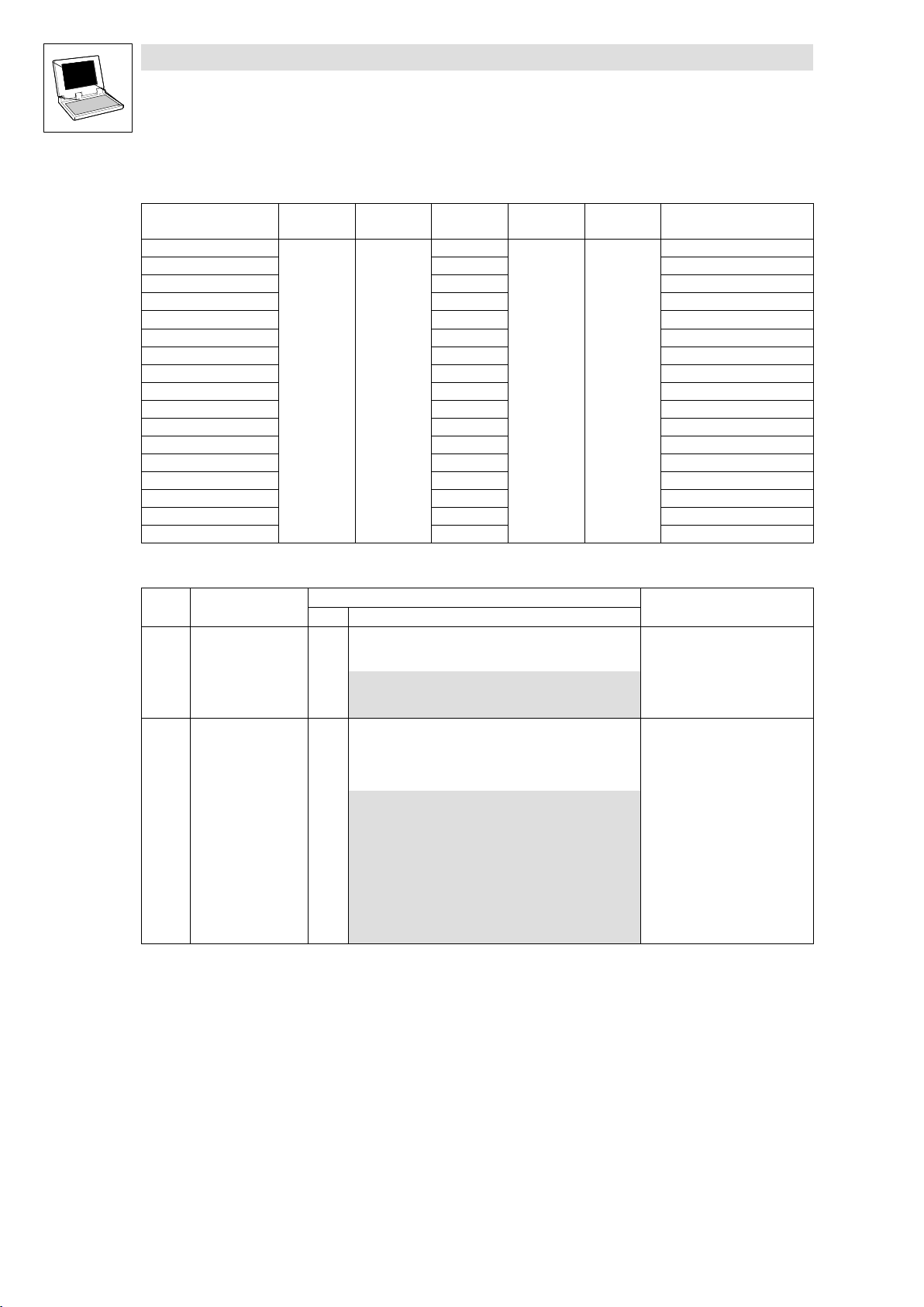
This documentation applies to the following Lenze PLC devices:
Type designation As from hardware version As from software version
9300 Servo PLC EVS93XX−xl 7A 8.0
9300 Servo PLC EVS93XX−xT 7A 8.0
What’s new?
Version Changes
1.4 07/2000 Revised edition for the 9300 Servo PLC as of software version V1.0
2.0 07/2001 Revised edition for the 9300 Servo PLC as of software version V2.0
3.0 01/2003 Revised edition for the 9300 Servo PLC as of software version V6.0
4.0/4.1 08/2006 Revised edition for the 9300 Servo PLC as of software version V7.0
5.0 10/2010 Revised edition for the 9300 Servo PLC as of software version V8.0
Important note:
The software is supplied to the user as described in this document. Any risks resulting from its quality or use remain the responsibility of the
user. The user must provide all safety measures protecting against possible maloperation.
We do not take any liability for direct or indirect damage, e.g. profit loss, order loss or any loss regarding business.
2010 Lenze Drive Systems GmbH
No part of this documentation may be copied or made available to third parties without the explicit written approval of Lenze Drive Systems
GmbH.
All information given in this documentation has been carefully selected and tested for compliance with the hardware and software described.
Nevertheless, discrepancies cannot be ruled out. We do not accept any responsibility or liability for any damage that may occur. Required
correction will be included in updates of this documentation.
All product names mentioned in this documentation are trademarks of the corresponding owners.
Version 5.0 10/2010
Page 3

9300 Servo PLC
Contents
1 Preface and general information 1−1 . . . . . . . . . . . . . . . . . . . . . . . . . . . . . . . . . . . . . . . . . . .
1.1 About this Manual 1−1 . . . . . . . . . . . . . . . . . . . . . . . . . . . . . . . . . . . . . . . . . . . . . . . . . . . . . . . . . . . . . . . .
1.1.1 Conventions used in this Manual 1−1 . . . . . . . . . . . . . . . . . . . . . . . . . . . . . . . . . . . . . . . . . . . . . .
1.1.2 System block descriptions 1−1 . . . . . . . . . . . . . . . . . . . . . . . . . . . . . . . . . . . . . . . . . . . . . . . . . . .
1.1.3 Pictographs in this Manual 1−2 . . . . . . . . . . . . . . . . . . . . . . . . . . . . . . . . . . . . . . . . . . . . . . . . . . .
1.1.4 Terminology used 1−2 . . . . . . . . . . . . . . . . . . . . . . . . . . . . . . . . . . . . . . . . . . . . . . . . . . . . . . . . .
1.2 System block introduction 1−3 . . . . . . . . . . . . . . . . . . . . . . . . . . . . . . . . . . . . . . . . . . . . . . . . . . . . . . . . . .
1.2.1 System block principle 1−3 . . . . . . . . . . . . . . . . . . . . . . . . . . . . . . . . . . . . . . . . . . . . . . . . . . . . . .
1.2.2 Node numbers 1−4 . . . . . . . . . . . . . . . . . . . . . . . . . . . . . . . . . . . . . . . . . . . . . . . . . . . . . . . . . . . .
1.2.3 Access via system variables 1−5 . . . . . . . . . . . . . . . . . . . . . . . . . . . . . . . . . . . . . . . . . . . . . . . . .
1.2.4 Access via absolute addresses 1−5 . . . . . . . . . . . . . . . . . . . . . . . . . . . . . . . . . . . . . . . . . . . . . . . .
1.2.5 Definition of inputs/outputs 1−6 . . . . . . . . . . . . . . . . . . . . . . . . . . . . . . . . . . . . . . . . . . . . . . . . . .
1.2.6 Linking of system blocks with DDS 1−7 . . . . . . . . . . . . . . . . . . . . . . . . . . . . . . . . . . . . . . . . . . . . .
1.2.7 Signal types and scalings 1−8 . . . . . . . . . . . . . . . . . . . . . . . . . . . . . . . . . . . . . . . . . . . . . . . . . . . .
2 System blocks 2−1 . . . . . . . . . . . . . . . . . . . . . . . . . . . . . . . . . . . . . . . . . . . . . . . . . . . . . . . . .
2.1 AIF1_IO_AutomationInterface (node number 41) 2−2 . . . . . . . . . . . . . . . . . . . . . . . . . . . . . . . . . . . . . . . . . .
2.1.1 Inputs_AIF1 2−2 . . . . . . . . . . . . . . . . . . . . . . . . . . . . . . . . . . . . . . . . . . . . . . . . . . . . . . . . . . . . . .
2.1.2 Outputs_AIF1 2−5 . . . . . . . . . . . . . . . . . . . . . . . . . . . . . . . . . . . . . . . . . . . . . . . . . . . . . . . . . . . .
2.2 AIF2_IO_AutomationInterface (node number 42) 2−7 . . . . . . . . . . . . . . . . . . . . . . . . . . . . . . . . . . . . . . . . . .
2.2.1 Inputs_AIF2 2−7 . . . . . . . . . . . . . . . . . . . . . . . . . . . . . . . . . . . . . . . . . . . . . . . . . . . . . . . . . . . . . .
2.2.2 Outputs_AIF2 2−9 . . . . . . . . . . . . . . . . . . . . . . . . . . . . . . . . . . . . . . . . . . . . . . . . . . . . . . . . . . . .
2.3 AIF3_IO_AutomationInterface (node number 43) 2−11 . . . . . . . . . . . . . . . . . . . . . . . . . . . . . . . . . . . . . . . . . .
2.3.1 Inputs_AIF3 2−11 . . . . . . . . . . . . . . . . . . . . . . . . . . . . . . . . . . . . . . . . . . . . . . . . . . . . . . . . . . . . . .
2.3.2 Outputs_AIF3 2−13 . . . . . . . . . . . . . . . . . . . . . . . . . . . . . . . . . . . . . . . . . . . . . . . . . . . . . . . . . . . .
2.4 AIF_IO_Management (node number 161) 2−15 . . . . . . . . . . . . . . . . . . . . . . . . . . . . . . . . . . . . . . . . . . . . . . .
2.4.1 Inputs_AIF_Management 2−15 . . . . . . . . . . . . . . . . . . . . . . . . . . . . . . . . . . . . . . . . . . . . . . . . . . . .
2.4.2 Outputs_AIF_Management 2−17 . . . . . . . . . . . . . . . . . . . . . . . . . . . . . . . . . . . . . . . . . . . . . . . . . . .
2.5 ANALOG1_IO (node number 11) 2−18 . . . . . . . . . . . . . . . . . . . . . . . . . . . . . . . . . . . . . . . . . . . . . . . . . . . . . .
2.5.1 Inputs_ANALOG1 (analog input) 2−18 . . . . . . . . . . . . . . . . . . . . . . . . . . . . . . . . . . . . . . . . . . . . . . .
2.5.2 Outputs_ANALOG1 (analog output) 2−19 . . . . . . . . . . . . . . . . . . . . . . . . . . . . . . . . . . . . . . . . . . . . .
2.6 ANALOG2_IO (node number 12) 2−20 . . . . . . . . . . . . . . . . . . . . . . . . . . . . . . . . . . . . . . . . . . . . . . . . . . . . . .
2.6.1 Inputs_ANALOG2 (analog input) 2−20 . . . . . . . . . . . . . . . . . . . . . . . . . . . . . . . . . . . . . . . . . . . . . . .
2.6.2 Outputs_ANALOG2 (analog output) 2−20 . . . . . . . . . . . . . . . . . . . . . . . . . . . . . . . . . . . . . . . . . . . . .
CAN1_IO (node number 31) . . . . . . . . . . . . . . . . . . . . . . . . . . . . . . . . . . . . . . . . . . . . . . . . . . . . . . . . .
CAN2_IO (node number 32) . . . . . . . . . . . . . . . . . . . . . . . . . . . . . . . . . . . . . . . . . . . . . . . . . . . . . . . . .
CAN3_IO (node number 33) . . . . . . . . . . . . . . . . . . . . . . . . . . . . . . . . . . . . . . . . . . . . . . . . . . . . . . . . .
CAN_Management (node number 101) . . . . . . . . . . . . . . . . . . . . . . . . . . . . . . . . . . . . . . . . . . . . . . . . .
CAN_Synchronization (node number 102) . . . . . . . . . . . . . . . . . . . . . . . . . . . . . . . . . . . . . . . . . . . . . . .
See "System bus (CAN) for Lenze PLCs" Manual.
L 9300 Servo PLC EN 5.0
i
Page 4

9300 Servo PLC
Contents
2.7 DCTRL_DriveControl (node number 121) 2−21 . . . . . . . . . . . . . . . . . . . . . . . . . . . . . . . . . . . . . . . . . . . . . . . .
2.7.1 Inputs_DCTRL 2−22 . . . . . . . . . . . . . . . . . . . . . . . . . . . . . . . . . . . . . . . . . . . . . . . . . . . . . . . . . . . .
2.7.2 Outputs_DCTRL 2−22 . . . . . . . . . . . . . . . . . . . . . . . . . . . . . . . . . . . . . . . . . . . . . . . . . . . . . . . . . . .
2.7.3 Quick stop (QSP) 2−23 . . . . . . . . . . . . . . . . . . . . . . . . . . . . . . . . . . . . . . . . . . . . . . . . . . . . . . . . . .
2.7.4 Operation disabled (DISABLE) 2−23 . . . . . . . . . . . . . . . . . . . . . . . . . . . . . . . . . . . . . . . . . . . . . . . . .
2.7.5 Controller inhibit (CINH) 2−24 . . . . . . . . . . . . . . . . . . . . . . . . . . . . . . . . . . . . . . . . . . . . . . . . . . . . .
2.7.6 Setting TRIP (TRIP−SET) 2−24 . . . . . . . . . . . . . . . . . . . . . . . . . . . . . . . . . . . . . . . . . . . . . . . . . . . . .
2.7.7 Resetting TRIP (TRIP−RESET) 2−25 . . . . . . . . . . . . . . . . . . . . . . . . . . . . . . . . . . . . . . . . . . . . . . . . .
2.7.8 Output of digital status signals 2−25 . . . . . . . . . . . . . . . . . . . . . . . . . . . . . . . . . . . . . . . . . . . . . . . .
2.7.9 Transfer of status/control word via AIF 2−27 . . . . . . . . . . . . . . . . . . . . . . . . . . . . . . . . . . . . . . . . . .
2.8 DFIN_IO_DigitalFrequency (node number 21) 2−28 . . . . . . . . . . . . . . . . . . . . . . . . . . . . . . . . . . . . . . . . . . . . .
2.8.1 Inputs_DFIN 2−28 . . . . . . . . . . . . . . . . . . . . . . . . . . . . . . . . . . . . . . . . . . . . . . . . . . . . . . . . . . . . .
2.9 DFOUT_IO_DigitalFrequency (node number 22) 2−35 . . . . . . . . . . . . . . . . . . . . . . . . . . . . . . . . . . . . . . . . . . .
2.9.1 Inputs_DFOUT / Outputs_DFOUT 2−35 . . . . . . . . . . . . . . . . . . . . . . . . . . . . . . . . . . . . . . . . . . . . . . .
2.10 DIGITAL_IO (node number 1) 2−39 . . . . . . . . . . . . . . . . . . . . . . . . . . . . . . . . . . . . . . . . . . . . . . . . . . . . . . . . .
2.10.1 Inputs_DIGITAL (digital inputs) 2−39 . . . . . . . . . . . . . . . . . . . . . . . . . . . . . . . . . . . . . . . . . . . . . . . .
2.10.2 Outputs_DIGITAL (digital outputs) 2−40 . . . . . . . . . . . . . . . . . . . . . . . . . . . . . . . . . . . . . . . . . . . . . .
2.11 FCODE_FreeCode (node number 141) 2−41 . . . . . . . . . . . . . . . . . . . . . . . . . . . . . . . . . . . . . . . . . . . . . . . . . .
2.12 MCTRL_MotorControl (node number 131) 2−44 . . . . . . . . . . . . . . . . . . . . . . . . . . . . . . . . . . . . . . . . . . . . . . .
2.12.1 Inputs_MCTRL 2−45 . . . . . . . . . . . . . . . . . . . . . . . . . . . . . . . . . . . . . . . . . . . . . . . . . . . . . . . . . . . .
2.12.2 Outputs_MCTRL 2−47 . . . . . . . . . . . . . . . . . . . . . . . . . . . . . . . . . . . . . . . . . . . . . . . . . . . . . . . . . .
2.12.3 Current controller 2−48 . . . . . . . . . . . . . . . . . . . . . . . . . . . . . . . . . . . . . . . . . . . . . . . . . . . . . . . . .
2.12.4 Torque setpoint / additional torque setpoint 2−49 . . . . . . . . . . . . . . . . . . . . . . . . . . . . . . . . . . . . . .
2.12.5 Torque limitation 2−50 . . . . . . . . . . . . . . . . . . . . . . . . . . . . . . . . . . . . . . . . . . . . . . . . . . . . . . . . . .
2.12.6 Maximum speed 2−51 . . . . . . . . . . . . . . . . . . . . . . . . . . . . . . . . . . . . . . . . . . . . . . . . . . . . . . . . . .
2.12.7 Speed controller 2−52 . . . . . . . . . . . . . . . . . . . . . . . . . . . . . . . . . . . . . . . . . . . . . . . . . . . . . . . . . .
2.12.8 Torque control with speed limitation 2−53 . . . . . . . . . . . . . . . . . . . . . . . . . . . . . . . . . . . . . . . . . . . .
2.12.9 Speed setpoint limitation 2−54 . . . . . . . . . . . . . . . . . . . . . . . . . . . . . . . . . . . . . . . . . . . . . . . . . . . .
2.12.10 Phase controller 2−54 . . . . . . . . . . . . . . . . . . . . . . . . . . . . . . . . . . . . . . . . . . . . . . . . . . . . . . . . . .
2.12.11 Quick stop (QSP) 2−55 . . . . . . . . . . . . . . . . . . . . . . . . . . . . . . . . . . . . . . . . . . . . . . . . . . . . . . . . . .
2.12.12 Field weakening 2−56 . . . . . . . . . . . . . . . . . . . . . . . . . . . . . . . . . . . . . . . . . . . . . . . . . . . . . . . . . .
2.12.13 Switching frequency changeover 2−56 . . . . . . . . . . . . . . . . . . . . . . . . . . . . . . . . . . . . . . . . . . . . . .
2.12.14 Feedback systems 2−57 . . . . . . . . . . . . . . . . . . . . . . . . . . . . . . . . . . . . . . . . . . . . . . . . . . . . . . . . .
2.12.15 Touch probe (TP) 2−58 . . . . . . . . . . . . . . . . . . . . . . . . . . . . . . . . . . . . . . . . . . . . . . . . . . . . . . . . . .
2.12.16 Manual adaptation of motor data 2−60 . . . . . . . . . . . . . . . . . . . . . . . . . . . . . . . . . . . . . . . . . . . . . .
2.12.17 Monitoring 2−62 . . . . . . . . . . . . . . . . . . . . . . . . . . . . . . . . . . . . . . . . . . . . . . . . . . . . . . . . . . . . . .
2.12.17.7 LP1 − monitoring of the motor phases 2−72 . . . . . . . . . . . . . . . . . . . . . . . . . . . . . . . . .
2.12.17.17 PL − monitoring of the rotor position adjustment 2−81 . . . . . . . . . . . . . . . . . . . . . . . . .
2.13 MCTRL_AUX_HighResFeedback (node number 181) 2−84 . . . . . . . . . . . . . . . . . . . . . . . . . . . . . . . . . . . . . . .
2.13.1 Inputs_MCTRL_AUX_HighResFeedback 2−84 . . . . . . . . . . . . . . . . . . . . . . . . . . . . . . . . . . . . . . . . .
2.13.2 Outputs_MCTRL_AUX_HighResFeedback 2−84 . . . . . . . . . . . . . . . . . . . . . . . . . . . . . . . . . . . . . . . .
2.14 STATEBUS_IO (node number 51) 2−85 . . . . . . . . . . . . . . . . . . . . . . . . . . . . . . . . . . . . . . . . . . . . . . . . . . . . . .
2.15 SYSTEM_FLAGS (system flags, node number 151) 2−86 . . . . . . . . . . . . . . . . . . . . . . . . . . . . . . . . . . . . . . . . .
2.15.1 Inputs SYSTEM_FLAGS 2−86 . . . . . . . . . . . . . . . . . . . . . . . . . . . . . . . . . . . . . . . . . . . . . . . . . . . . .
2.15.2 Outputs SYSTEM_FLAGS 2−87 . . . . . . . . . . . . . . . . . . . . . . . . . . . . . . . . . . . . . . . . . . . . . . . . . . . .
ii
9300 Servo PLC EN 5.0
L
Page 5

9300 Servo PLC
Contents
3 Appendix 3−1 . . . . . . . . . . . . . . . . . . . . . . . . . . . . . . . . . . . . . . . . . . . . . . . . . . . . . . . . . . . . .
3.1 PLC functionality 3−1 . . . . . . . . . . . . . . . . . . . . . . . . . . . . . . . . . . . . . . . . . . . . . . . . . . . . . . . . . . . . . . . . .
3.2 Extendability/networking 3−2 . . . . . . . . . . . . . . . . . . . . . . . . . . . . . . . . . . . . . . . . . . . . . . . . . . . . . . . . . . .
3.3 Memories 3−3 . . . . . . . . . . . . . . . . . . . . . . . . . . . . . . . . . . . . . . . . . . . . . . . . . . . . . . . . . . . . . . . . . . . . . .
3.3.1 Retain memory 3−4 . . . . . . . . . . . . . . . . . . . . . . . . . . . . . . . . . . . . . . . . . . . . . . . . . . . . . . . . . . .
3.3.2 Persistent memory 3−5 . . . . . . . . . . . . . . . . . . . . . . . . . . . . . . . . . . . . . . . . . . . . . . . . . . . . . . . .
3.3.3 Downloading data 3−6 . . . . . . . . . . . . . . . . . . . . . . . . . . . . . . . . . . . . . . . . . . . . . . . . . . . . . . . . .
3.4 System POUs 3−7 . . . . . . . . . . . . . . . . . . . . . . . . . . . . . . . . . . . . . . . . . . . . . . . . . . . . . . . . . . . . . . . . . . . .
3.5 System error messages 3−8 . . . . . . . . . . . . . . . . . . . . . . . . . . . . . . . . . . . . . . . . . . . . . . . . . . . . . . . . . . . .
3.5.1 Overview of system error messages, error sources and responses 3−9 . . . . . . . . . . . . . . . . . . . . . .
3.5.2 Response and its effects on the drive 3−12 . . . . . . . . . . . . . . . . . . . . . . . . . . . . . . . . . . . . . . . . . . .
3.5.3 System error message reset 3−12 . . . . . . . . . . . . . . . . . . . . . . . . . . . . . . . . . . . . . . . . . . . . . . . . .
3.5.4 Causes and remedies 3−13 . . . . . . . . . . . . . . . . . . . . . . . . . . . . . . . . . . . . . . . . . . . . . . . . . . . . . .
3.5.5 Fault analysis via the fault memory 3−17 . . . . . . . . . . . . . . . . . . . . . . . . . . . . . . . . . . . . . . . . . . . .
3.5.6 Fault analysis via the LED display of the PLC 3−19 . . . . . . . . . . . . . . . . . . . . . . . . . . . . . . . . . . . . .
3.5.7 Fault analysis via the 9371BB keypad 3−19 . . . . . . . . . . . . . . . . . . . . . . . . . . . . . . . . . . . . . . . . . .
3.5.8 Fault analysis via the LECOM status word C0150 3−19 . . . . . . . . . . . . . . . . . . . . . . . . . . . . . . . . . .
3.6 Code table 3−20 . . . . . . . . . . . . . . . . . . . . . . . . . . . . . . . . . . . . . . . . . . . . . . . . . . . . . . . . . . . . . . . . . . . . . .
3.6.1 Temporary codes 3−52 . . . . . . . . . . . . . . . . . . . . . . . . . . . . . . . . . . . . . . . . . . . . . . . . . . . . . . . . . .
3.6.2 RAM access via codes 3−52 . . . . . . . . . . . . . . . . . . . . . . . . . . . . . . . . . . . . . . . . . . . . . . . . . . . . . .
3.7 Attribute table 3−55 . . . . . . . . . . . . . . . . . . . . . . . . . . . . . . . . . . . . . . . . . . . . . . . . . . . . . . . . . . . . . . . . . . .
4 Index 4−1 . . . . . . . . . . . . . . . . . . . . . . . . . . . . . . . . . . . . . . . . . . . . . . . . . . . . . . . . . . . . . . . .
L 9300 Servo PLC EN 5.0
iii
Page 6

9300 Servo PLC
Contents
iv
9300 Servo PLC EN 5.0
L
Page 7
Preface and general information
1 Preface and general information
1.1 About this Manual
This Manual describes the system block functions which can be selected and parameterised in the
control configuration of the Drive PLC Developer Studio (DDS) for 9300 Servo PLC.
1.1.1 Conventions used in this Manual
This Manual uses the following conventions to distinguish between different types of information:
Information type Distinction (in text) Example
System block name bold The SB DIGITAL_IO...
System (block) variable identifier italics The input DIGIN_bIn1_b...
9300 Servo PLC
Tip!
Information about the conventions used for variable names of Lenze system blocks, function blocks
and functions can be obtained from the appendix of the DDS online documentation "Introduction
into IEC 61131−3 programming". The conventions ensure universal and uniform naming and support
the readability of PLC programs.
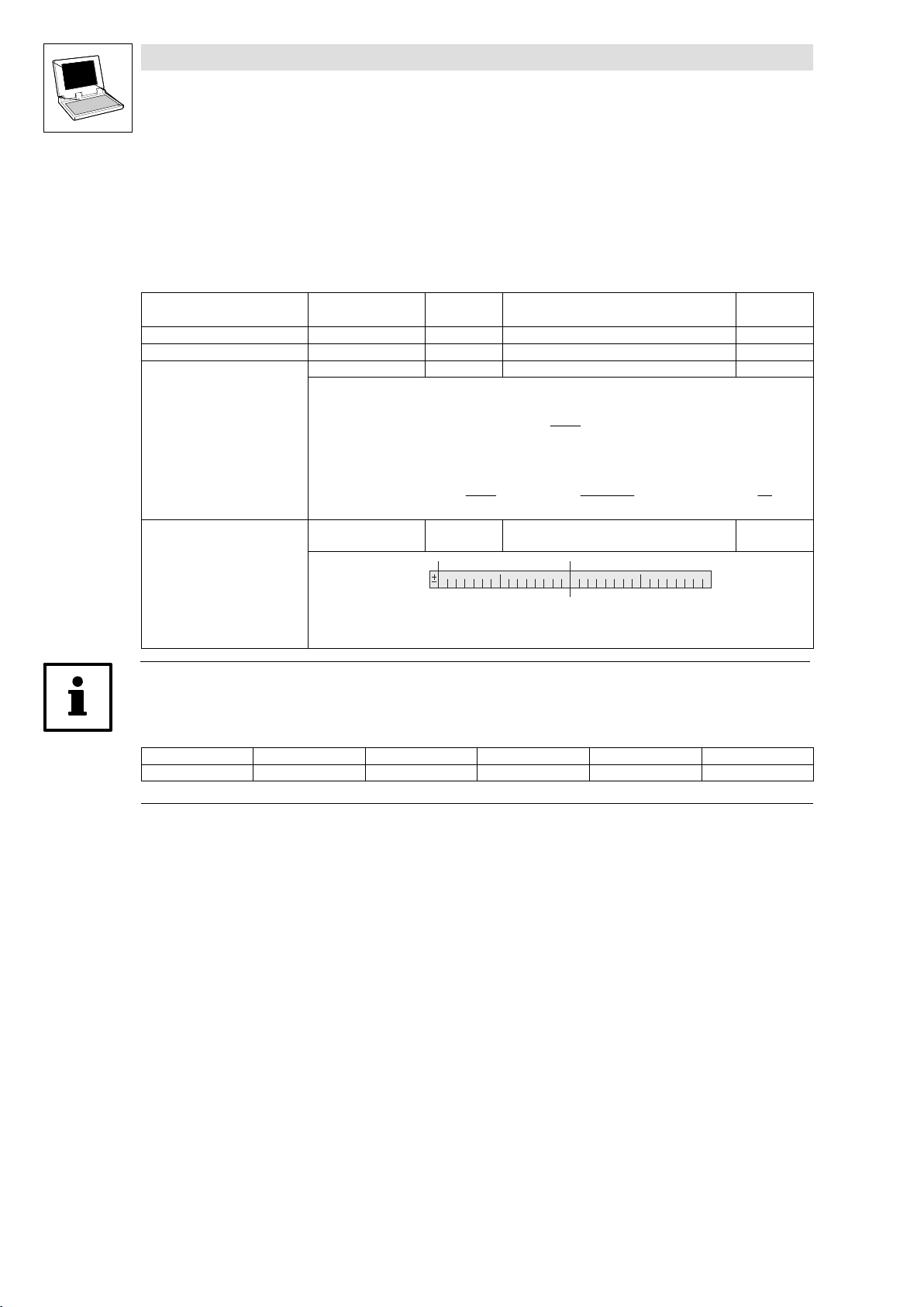
1.1.2 System block descriptions
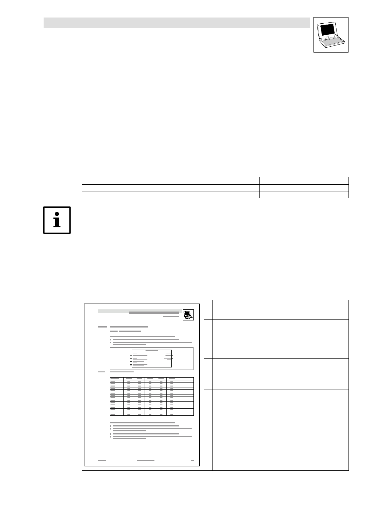
All system block descriptions given in this Manual have the same structure:
Headline with SB identifier
SB function and node number
Short description of the SB and its most important features
System block chart including all corresponding variables
Input variables
Output variables
Table giving information about input and output variables:
Identifier
Data type
Signal type
Address
Display code
Display format
Info
l
Detailed SB description
9300 Servo PLC EN 5.0
1−1
Page 8
9300 Servo PLC
Preface and general information
1.1.3 Pictographs in this Manual
Pictographs
used
Warning of material
damage
More notes Tip!
1.1.4 Terminology used
Term In this Manual used for
AIF Automation interface
DDS Drive PLC Developer Studio
FIF Function interface
GDC Global Drive Control (parameter setting program from Lenze)
SB System block
System bus System bus (CAN): Lenze standard bus system similar to CANopen
Signal words
Stop! Warns of potential damage to material.
Note!
Possible consequences if disregarded:
Damage of the PLC or its environment
Indicates a tip or note.
.
1−2
9300 Servo PLC EN 5.0
l
Page 9
1.2 System block introduction
For a long time, Lenze has followed the principle of describing controller functions with the aid of
function blocks (FBs). This principle can also be found in the IEC 61131−3 standard.
Functions which can be used as software functions in projects are stored in function libraries
as function blocks or functions.
In addition, quasi−hardware functions are available as system blocks (SBs).
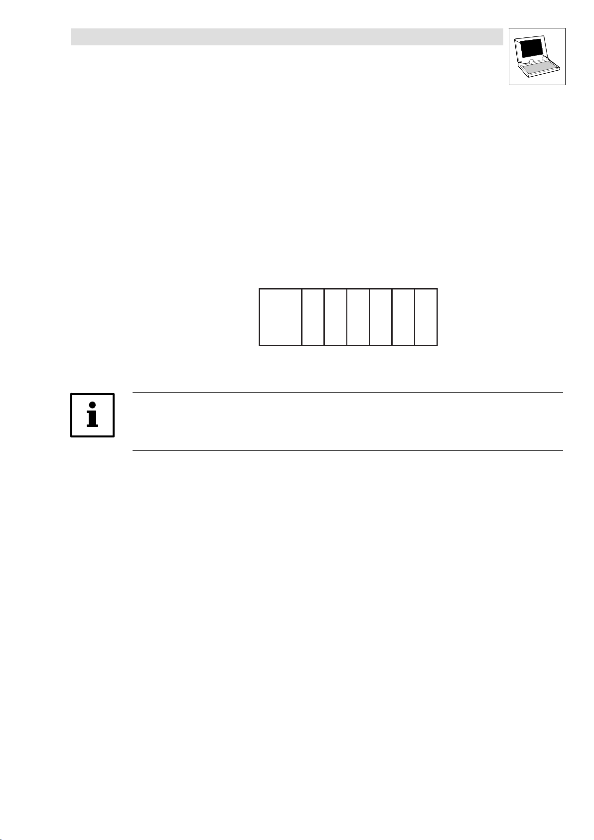
1.2.1 System block principle
The system−block principle can be explained by means of a PLC system in a rack:
The rack contains the CPU, digital I/Os, analog I/Os, counter card, positioning card, etc. as
additional cards:
9300 Servo PLC
Preface and general information
CPU
The CPU can directly access the additional cards and process the resulting information.
Additional cards have fixed addresses for access.
With Lenze PLC controllers, system blocks can be compared with these additional cards!
System blocks are special (hardware) function blocks permanently integrated into the
run−time system of the PLC.
SBs can address real hardware.
SBs are assigned/identified through so−called node numbers. (^ 1−4)
SB inputs and outputs are accessed via system variables or absolute memory addresses.
(^ 1−5)
Inputs/outputs are always classified from the program’s point of view. (^ 1−6)
Required SBs must be explicitly linked to the project via the control configuration of DDS.
(^ 1−7)
xxxxxx
x = Additional cards
l
9300 Servo PLC EN 5.0
1−3
Page 10
9300 Servo PLC
Preface and general information
1.2.2 Node numbers
The system blocks of the 9300 Servo PLC carry the following node numbers:
Node number System block Notes
1 DIGITAL_IO Digital inputs/outputs
11 ANALOG1_IO Analog inputs/outputs 1
12 ANALOG2_IO Analog inputs/outputs 2
21 DFIN_IO_DigitalFrequency Digital frequency input
22 DFOUT_IO_DigitalFrequency Digital frequency output
31 CAN1_IO
32 CAN2_IO
33 CAN3_IO
41 AIF1_IO_AutomationInterface
42 AIF2_IO_AutomationInterface
43 AIF3_IO_AutomationInterface
51 STATEBUS_IO State bus
60 OSC_Oscilloscope Oscilloscope function
101 CAN_Management System bus (CAN) management
102 CAN_Syncronization System bus (CAN) synchronisation
121 DCTRL_DriveControl Device control
131 MCTRL_MotorControl Motor control
141 FCODE_FreeCodes Free codes
151 SYSTEM_FLAGS System flags
161 AIF_IO_Management Automation interface management
171 VAR_PERSISTENT Persistent variables
1
SBs for system bus (CAN) are described in the "System bus (CAN) for Lenze PLC devices" manual.
The node number is part of the absolute SB address (see chapter 2). (^ 1−5)
181 MCTRL_AUX_HighResFeedback High−resolution encoder signal
System bus (CAN)
Automation interface
1
1
1
1−4
9300 Servo PLC EN 5.0
l
Page 11
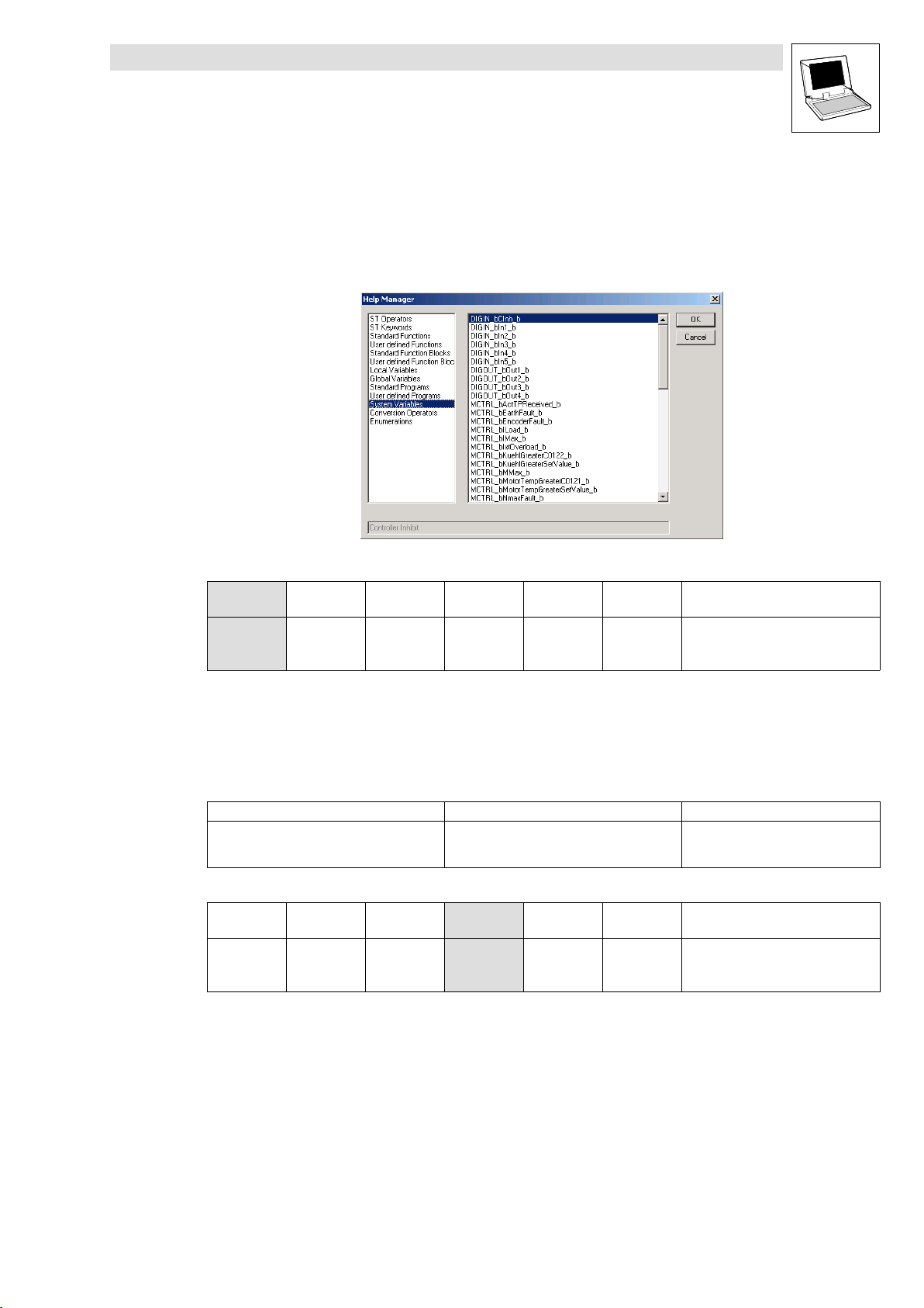
1.2.3 Access via system variables
You can use the system variables of a system block in your project after the system block has been
integrated into the control configuration of the DDS.
Open the input assistance in the DDS editors via <F2> to get a listing of all available system
variables:
9300 Servo PLC
Preface and general information
This Manual lists the system variables in the table for the corresponding system block:
Variable Data type Signal type Address Display
DIGIN_bIn1_b
... ... ...
DIGIN_bIn8_b %IX1.0.7 C0443/8
Example: Table with SB DIGITAL_IO inputs of the Drive PLC
Bool Binary
%IX1.0.0 C0443/1
1.2.4 Access via absolute addresses
System block inputs and outputs can also be accessed via absolute addresses according to the
IEC61131−3 standard:
For inputs use: For outputs use:
%IXa.b.c %QXa.b.c
This Manual lists the absolute addresses in the table for the corresponding system block:
Variable Data type Signal type Address Display
DIGIN_bIn1_b
... ... ...
DIGIN_bIn8_b %IX1.0.7 C0443/8
Example: Table with SB DIGITAL_IO inputs of the Drive PLC
Bool Binary
%IX1.0.0 C0443/1
code
code
Display
format
bin
Display
format
bin
Note
a = node number
b = word address
c = bit address
Note
l
9300 Servo PLC EN 5.0
1−5
Page 12
9300 Servo PLC
Preface and general information
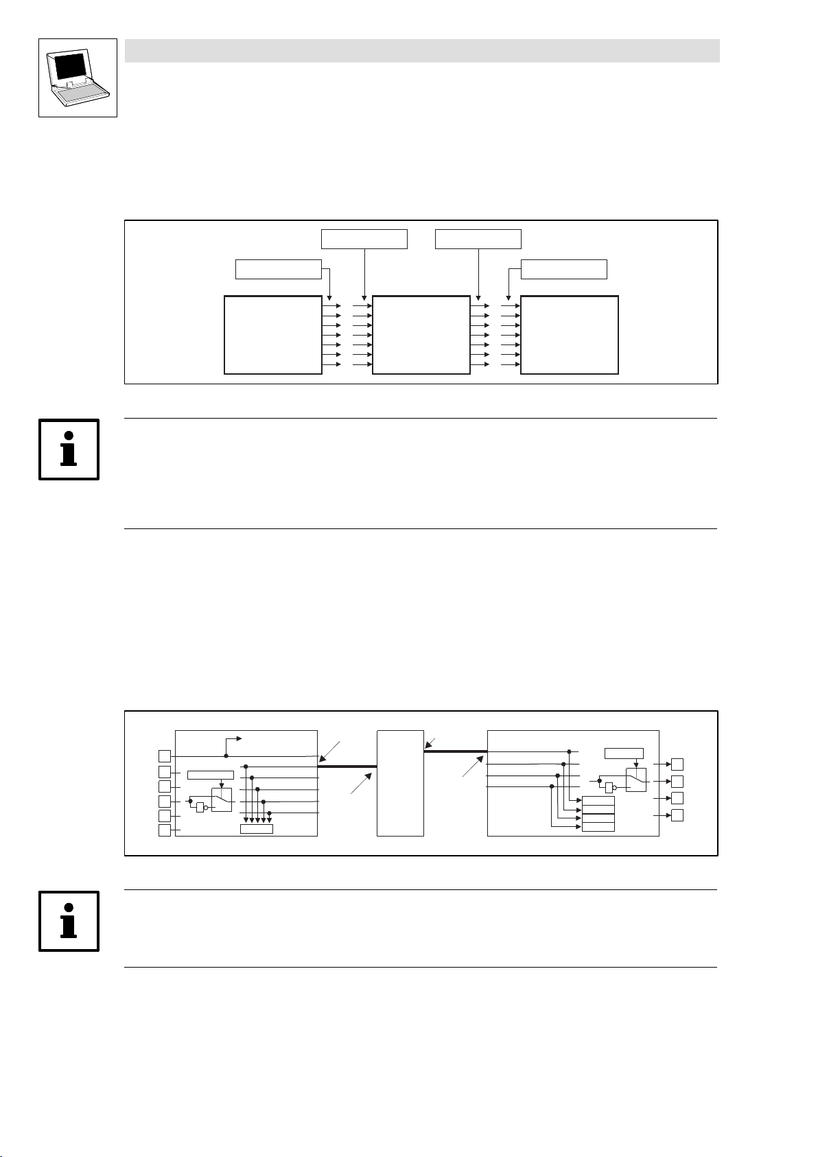
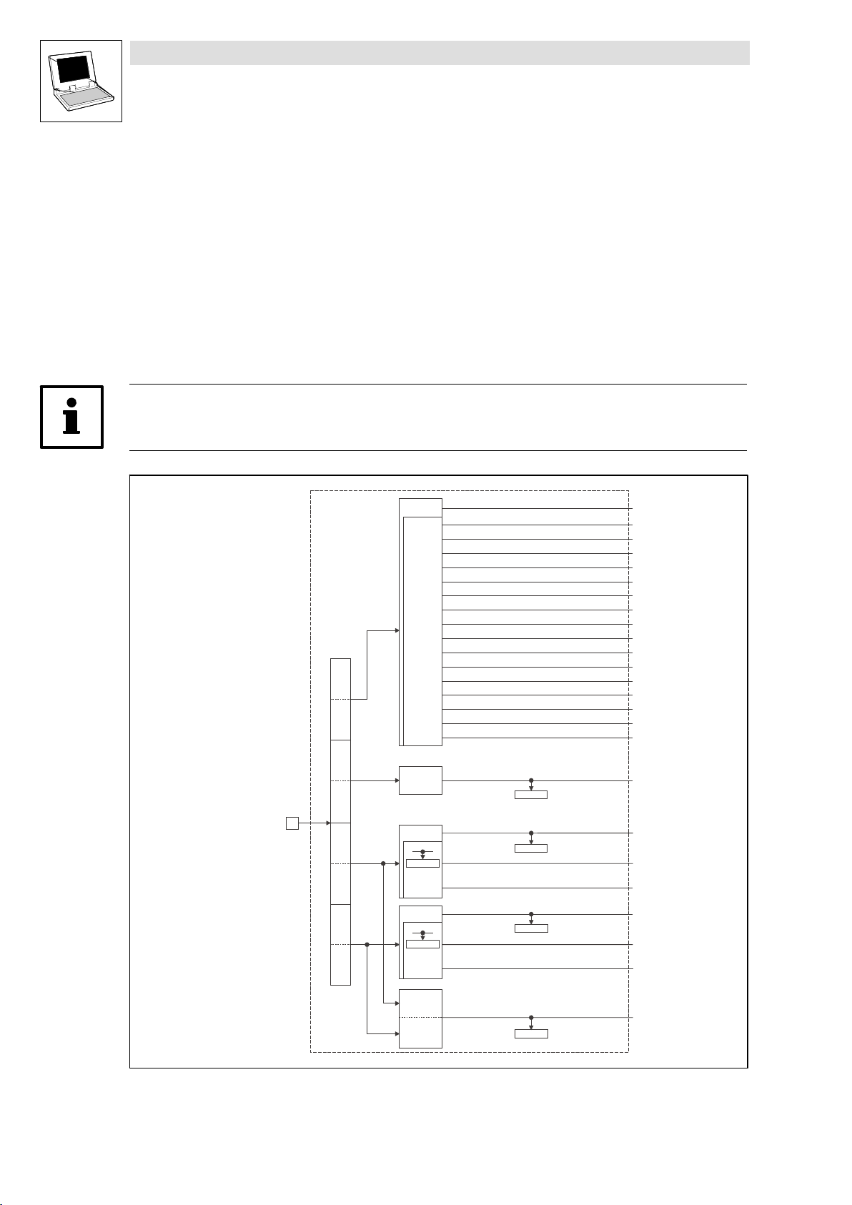
1.2.5 Definition of inputs/outputs
The application program is connected with the hardware by linking system blocks with program
organisation units (POUs):
SB-Output SB-Input
POU-Input POU-Output
SB
POU
Fig. 1−1 Principle: Linking of system blocks with a program organisation unit (POU)
Tip!
Inputs and outputs are always classified from the program’s point of view.
Logic SB inputs are hardware outputs of the PLC.
Logic SB outputs are hardware inputs of the PLC.
Example: System block DIGITAL_IO of the 9300 Servo PLC
If you want to use the digital input 1 and the digital output 1 of the 9300 Servo PLC, proceed as
follows:
1. Link the SB DIGITAL_IO explicitly with the DDS control configuration.
2. Access to digital input 1:
Assign the system variable DIGIN_bIn1_b to a POU input.
3. Access to digital output 1:
Assign the system variable DIGOUT_bOut1_b to a POU output.
POU
POU-OUT
SB-IN
SB-OUT
POU-IN
0
1
DCTRL -X5/28
DIGIN_bCInh_b
DIGIN_bIn1_b
DIGIN_bIn2_b
DIGIN_bIn3_b
DIGIN_bIn4_b
DIGIN_bIn5_b
C0443
DIGIN
X5
28
E1
C0114/1...5
E2
E3
1
E4
E5
DIGOUT_bOut1_b
DIGOUT_bOut2_b
DIGOUT_bOut3_b
DIGOUT_bOut4_b
SB
(^ 1−7)
C0444/1
C0444/2
C0444/3
C0444/4
DIGOUT
C0118/1...4
0
1
1
X5
A1
A2
A3
A4
Fig. 1−2 Principle: Linking of the 9300 Servo PLC system block DIGITAL_IO with a POU
Tip!
According to the IEC61131−3 standard, only one copy of the digital input 1 and the digital output 1
may be transferred.
1−6
9300 Servo PLC EN 5.0
l
Page 13
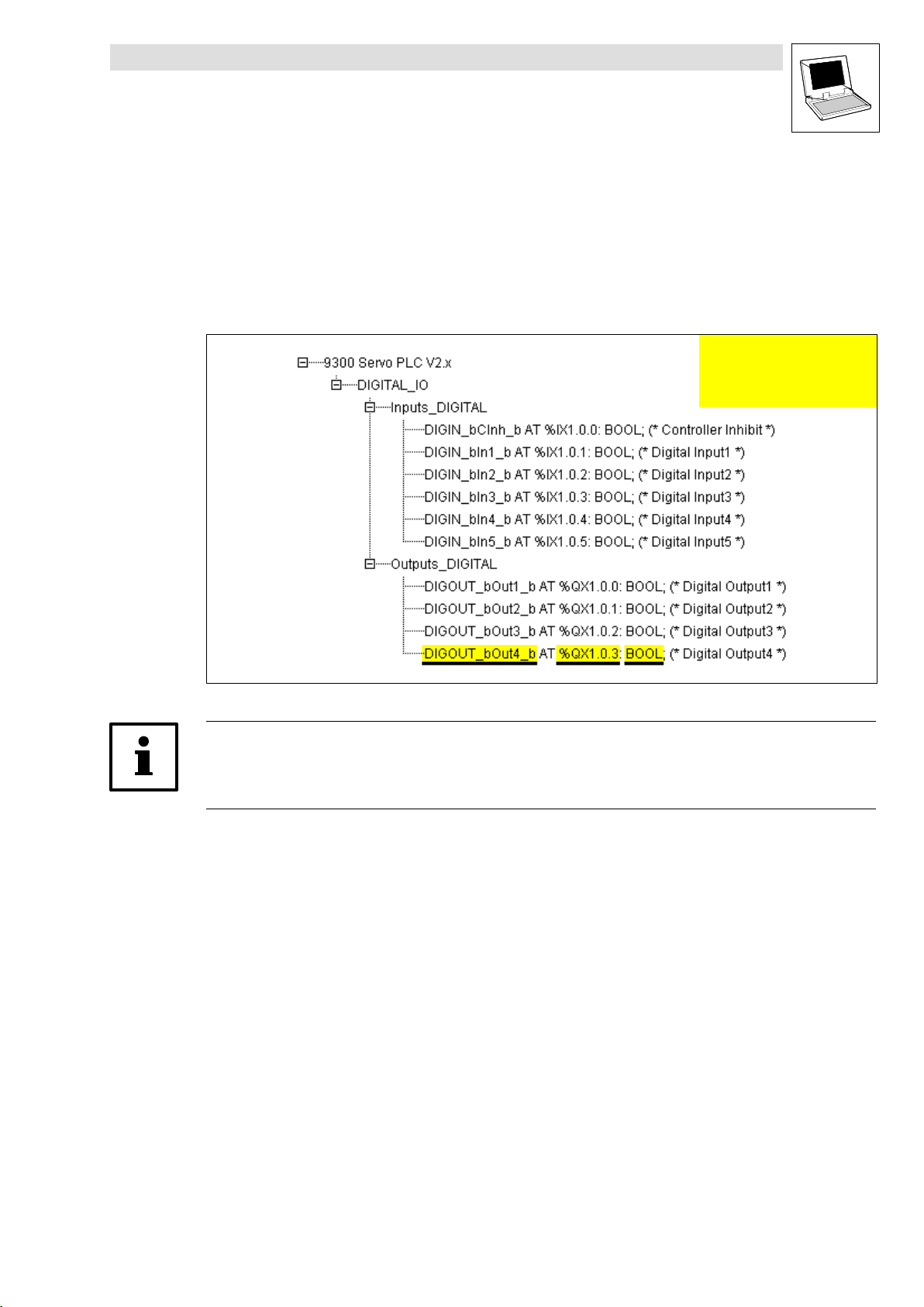
1.2.6 Linking of system blocks with DDS
The system blocks required must be explicitly linked to the project via the control configuration of the
DDS.
The control configuration is placed as an object in the Resources tab in the Object organiser.
The control configuration lists all inputs and outputs including the identifiers of the
corresponding I/O variable, the absolute address and the data type of the I/O variable for
every linked SB.
9300 Servo PLC
Preface and general information
Identifier of the I/O variable
Absolute address
Data type of the I/O variable
Fig. 1−3 Example: Control configuration for 9300 Servo PLC with linked SB DIGITAL_IO
Tip!
The control configuration provides a context menu for adding and deleting SBs which can be
activated via the right mouse key.
l
9300 Servo PLC EN 5.0
1−7
Page 14
9300 Servo PLC
Preface and general information
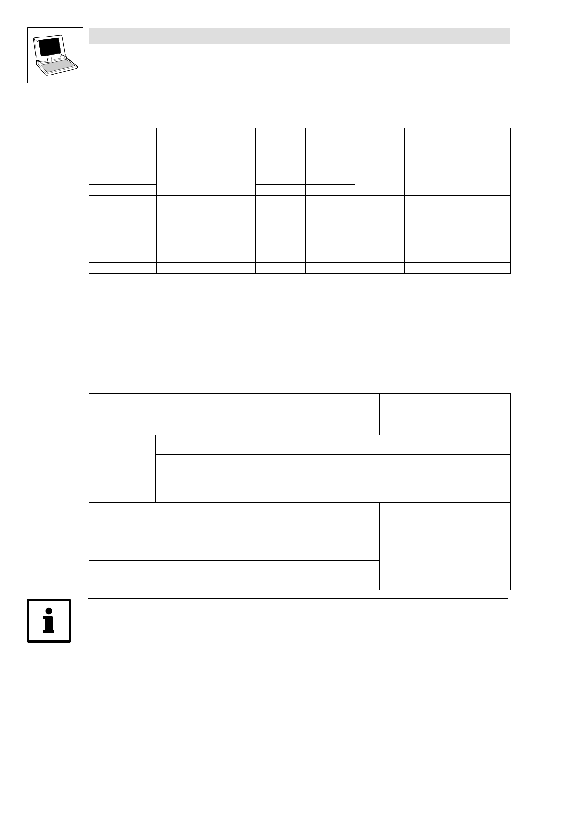
1.2.7 Signal types and scalings
Most inputs and outputs of Lenze function blocks/system blocks can be assigned to a certain signal
type. We distinguish between digital, analog, position and speed signals.
The identifier of the corresponding input/output variable has an ending (starting with an underscore).
It indicates the signal type.
Signal type Ending Memory
Analog _a (analog) 16 bits 100 % 16384 H
Digital _b (binary) 8 bits 0 FALSE; 1 TRUE G
Phase difference or speed
Phase−angle or position _p (position) 32 bits 1 motor revolution 65536 E
_v (velocity) 16 bits 15000 rpm 16384 F
Phase difference/speed ref. to 1 ms
Scaling example:
Speed (on motor side) + 15000 [rpm] +
1 motor revolution + 65536 [inc]
Variable value (..._v) +
space
Direction (0 clockwise rotation; 1 counter−clockwise rotation)
No. of motor revolutions (0 ... 32767)
Phase angle or position (0 ... 65535)
Scaling
(external value º internal value)
15000
60 [s]
15000
@ 65536 [inc] +
60 [s]
High Word Low Word 031
15000
60000 [ms]
@ 65536 [inc] + 16384
Previous
identification
inc
ƪ
ƫ
ms
Note!
Due to their scaling, analog signals have an asymmetrical resolution range (−200 % ... +199.99 %):
External value: −200 % −100 % 0 +100 % +199.99 %
Internal value: −32768 −16384 0 +16384 +32767
1−8
9300 Servo PLC EN 5.0
l
Page 15

2 System blocks
The following sections inform about the system blocks of the basic unit.
9300 Servo PLC
System blocks
L
9300 Servo PLC EN 5.0
2−1
Page 16
9300 Servo PLC
System blocks
2.1 AIF1_IO_AutomationInterface (node number 41)
2.1 AIF1_IO_AutomationInterface (node number 41)
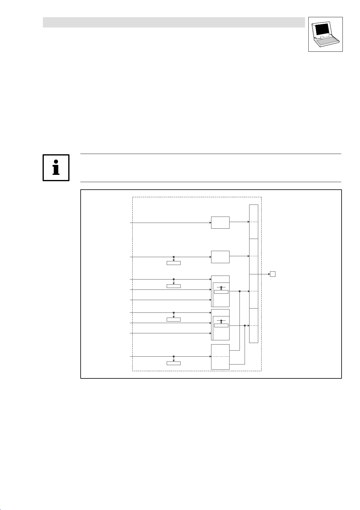
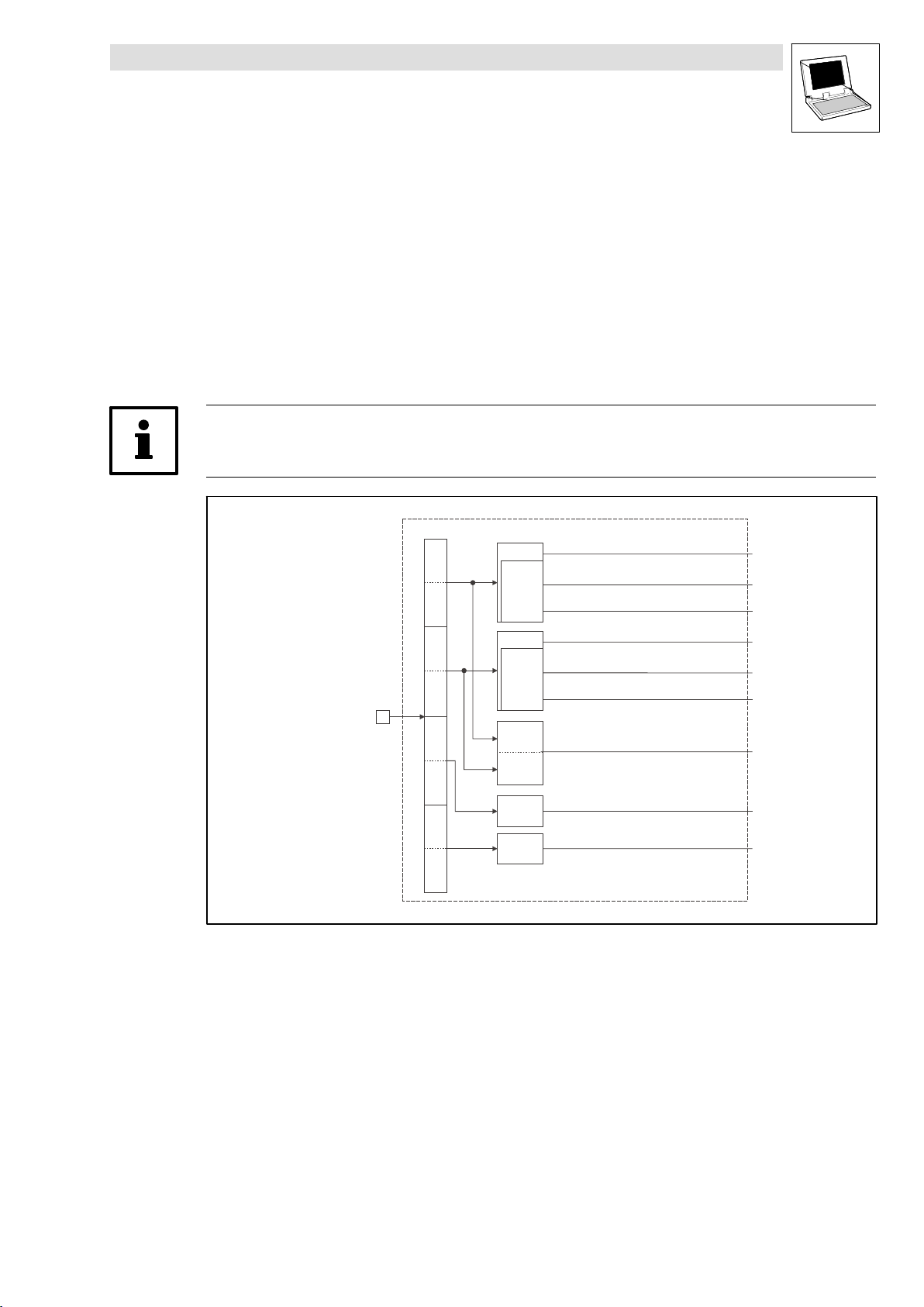
2.1.1 Inputs_AIF1
This SB is used as an interface for input signals (e.g. setpoints/actual values) from attached fieldbus
modules (e.g. INTERBUS, PROFIBUS−DP).
The process image is
– created in the cyclic task in a fixed time interval of 10 ms.
– created in an interval task within the time set for this task.
– read at the beginning of the task and written at its end.
Tip!
Please observe the Operating Instructions for the attached fieldbus module.
Automation
Interface
Inputs_AIF1
Byte
1
Controlword
Byte
2
Byte
3
Byte
4
Byte
5
Byte
6
Byte
7
Byte
8
16 Bit
16 binary
signals
16 Bit
16 Bit
C0855/1
16 binary
signals
16 Bit
C0855/2
16 binary
signals
C0856/1
C0856/2
C0856/3
AIF1_wDctrlCtrl
AIF1_bCtrlB0_b
AIF1_bCtrlB1_b
AIF1_bCtrlB2_b
AIF1_bCtrlQuickstop_b
AIF1_bCtrlB4_b
AIF1_bCtrlB5_b
AIF1_bCtrlB6_b
AIF1_bCtrlB7_b
AIF1_bCtrlDisable_b
AIF1_bCtrlCInhibit_b
AIF1_bCtrlTripSet_b
AIF1_bCtrlTripReset_b
AIF1_bCtrlB12_b
AIF1_bCtrlB13_b
AIF1_bCtrlB14_b
AIF1_bCtrlB15_b
AIF1_nInW1_a
AIF1_nInW2_a
AIF1_bInB0_b
…
AIF1_bInB15_b
AIF1_nInW3_a
AIF1_bIn16_b
…
AIF1_bIn31_b
Fig. 2−1 Inputs_AIF1
2−2
16 Bit
LowWord
16 Bit
HighWord
9300 Servo PLC EN 5.0
AIF1_dnInD1_p
C0857
L
Page 17
9300 Servo PLC
System blocks
2.1 AIF1_IO_AutomationInterface (node number 41)
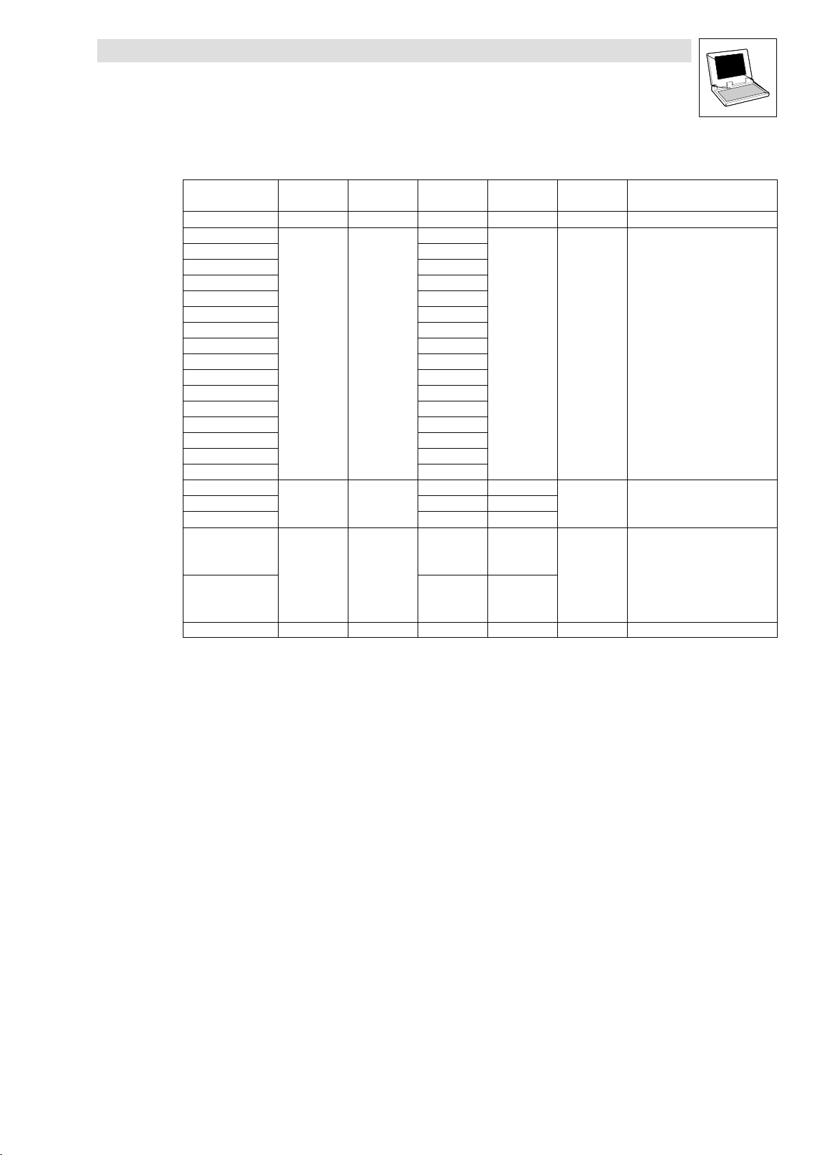
System variables
Variable Data type Signal type Address Display
AIF1_wDctrlCtrl Word − %IX41.0 C0136/3 hex
AIF1_bCtrlB0_b
AIF1_bCtrlB1_b
AIF1_bCtrlB2_b
AIF1_bCtrlQuickstop_b
AIF1_bCtrlB4_b
AIF1_bCtrlB5_b
AIF1_bCtrlB6_b
AIF1_bCtrlB7_b
AIF1_bCtrlDisable_b
AIF1_bCtrlCInhibit_b
AIF1_bCtrlTripSet_b
AIF1_bCtrlTripReset_b
AIF1_bCtrlB12_b
AIF1_bCtrlB13_b
AIF1_bCtrlB14_b
AIF1_bCtrlB15_b
AIF1_nInW1_a
AIF1_nInW2_a
AIF1_nInW3_a
AIF1_bInB0_b
...
AIF1_bInB15_b
AIF1_bInB16_b
...
AIF1_bInB31_b
AIF1_dnInD1_p Double integer Position %ID41.1 C0857 dec [inc]
Bool Binary
Integer Analog
Bool Binary
%IX41.0.0
%IX41.0.1
%IX41.0.2
%IX41.0.3
%IX41.0.4
%IX41.0.5
%IX41.0.6
%IX41.0.7
%IX41.0.8
%IX41.0.9
%IX41.0.10
%IX41.0.11
%IX41.0.12
%IX41.0.13
%IX41.0.14
%IX41.0.15
%IW41.1 C0856/1
%IW41.2 C0856/2
%IW41.3 C0856/3
%IX41.2.0
...
%IX41.2.15
%IX41.3.0
...
%IX41.3.15
code
C0136/3 bin
C0855/1
C0855/2
Display
format
dec [%]
hex
Note
L
9300 Servo PLC EN 5.0
2−3
Page 18
9300 Servo PLC
System blocks
2.1 AIF1_IO_AutomationInterface (node number 41)
User data
The received 8 bytes of user data are assigned to several variables of different data types
simultaneously. Thus the data can be evaluated in the PLC program as
binary information (1 bit)
control word/quasi−analog value (16 bits)
phase information (32 bits)
according to the requirements.
Byte Variable (1 bit) Variable (16 bits) Variable (32 bits)
1, 2
Notes:
3, 4
AIF1_bInB0_b
AIF1_bInB1_b
AIF1_bInB2_b
AIF1_bCtrlQuickstop_b
AIF1_bInB4_b
...
AIF1_bInB7_b
AIF1_bCtrlDisable_b
AIF1_bCtrlCInhibit_b
AIF1_bCtrlTripSet_b
AIF1_bCtrlTripReset_b
AIF1_bInB12_b
...
AIF1_bInB15_b
Drive PLC:
All variables assigned to byte 1/2 can be freely used in the PLC program.
9300 Servo PLC:
The assignment of the controller−internal control word to byte 1/2 is not a fixed assignment.
Byte 1/2 can, however, be used to write the signals for the quick stop (QSP), DISABLE, CINH, TRIP−SET and
TRIP−RESET functions to the SB DCTRL_DriveControl.
– To do this, connect the variable AIF1_wDctrlCtrl with the variable DCTRL_wAIF1Ctrl of the SB
DCTRL_DriveControl.
The signals can also be read and processed via the following variables:
– AIF1_bCtrlQuickstop_b
– AIF1_bCtrlDisable_b
– AIF1_bCtrlCInhibit_b
– AIF1_bCtrlTripSet_b
– AIF1_bCtrlTripReset_b
AIF1_wDctrlCtrl
AIF1_nInW1_a
2−4
5, 6 AIF1_bInB0_b
...
AIF1_bInB15_b
7, 8 AIF1_bInB16_b
...
AIF1_bInB31_b
AIF1_nInW2_a
AIF1_nInW3_a
9300 Servo PLC EN 5.0
AIF1_dnInD1_p
L
Page 19
9300 Servo PLC
System blocks
2.1 AIF1_IO_AutomationInterface (node number 41)
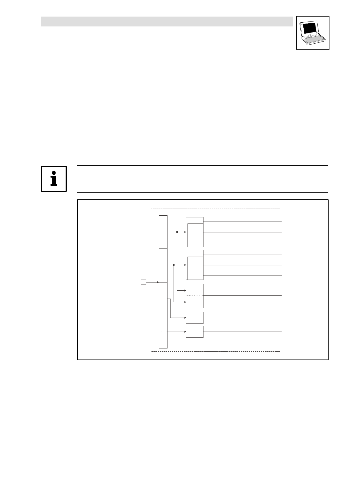
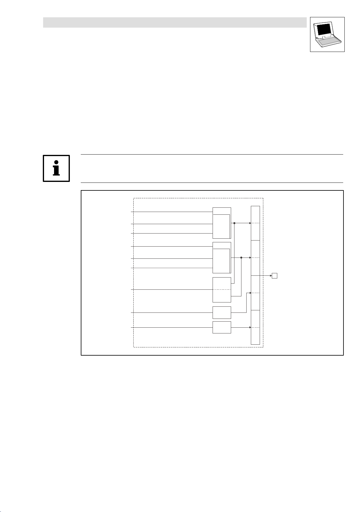
2.1.2 Outputs_AIF1
This SB is used as an interface for output signals (e.g. setpoints/actual values) to attached fieldbus
modules (e.g. INTERBUS, PROFIBUS−DP).
The process image is
– created in the cyclic task in a fixed time interval of 10 ms.
– created in an interval task within the time set for this task.
– read at the beginning of the task and written at its end.
Tip!
Please observe the Operating Instructions for the attached fieldbus module.
Outputs_AIF1
Fig. 2−2 Outputs_AIF1
AIF1_wDctrlStat
AIF1_nOutW1_a
AIF1_nOutW2__a
AIF1_bFDO0_b
…
AIF1_bFDO15_b
AIF1_nOutW3_a
AIF1_bFDO16_b
…
AIF1_bFDO31_b
AIF1_dnOutD1_p
C0858/1
C0858/2
C0858/3
C0859
16 Bit
16 Bit
16 Bit
C0151/4
16 binary
signals
16 Bit
C0151/4
16 binary
signals
16 Bit
LowWord
16 Bit
HighWord
Byte
Byte
Byte
Byte
Byte
Byte
Byte
Byte
1
2
3
4
5
6
7
8
Automation
Interface
L
9300 Servo PLC EN 5.0
2−5
Page 20
9300 Servo PLC
System blocks
2.1 AIF1_IO_AutomationInterface (node number 41)
System variables
Variable Data type Signal type Address Display
AIF1_wDctrlStat Word − %QW41.0 − −
AIF1_nOutW1_a
AIF1_nOutW2_a %QW41.2 C0858/2
AIF1_nOutW3_a %QW41.3 C0858/3
AIF1_bFDO0_b
.. ...
AIF1_bFDO15_b %QX41.2.15
AIF1_bFDO16_b %QX41.3.0
.. ...
AIF1_bFDO31_b %QX41.3.15
AIF1_dnOutD1_p Double integer Position %QD41.1 C0859 dec [inc]
Integer Analog
Bool Binary
%QW41.1 C0858/1
%QX41.2.0
code
C0151/4 hex
Display
format
dec [%]
Note
Display code in hex
as double word
User data
The 8 bytes of user data to be sent can be written to via several variables of different data types
simultaneously. Thus the data can be transferred by the PLC program as
binary information (1 bit)
status word/quasi−analog value (16 bits)
phase information (32 bits)
according to the requirements.
Byte Variable (1 bit) Variable (16 bits) Variable (32 bits)
1, 2
AIF1_wDctrlStat
Notes:
Drive PLC:
All variables assigned to byte 1/2 can be written to by the PLC program.
9300 Servo PLC:
Bytes 1 and 2 can be used to transfer the status word from the SB DCTRL_DriveControl.
To do this, connect the variable DCTRL_wStat of the SB DCTRL_DriveControl with the variable AIF1_wDctrlStat.
In addition to signals such as IMP and CINH, the SB DCTRL_DriveControl status word contains some freely
assignable signals which can be written to via the variables DCTRL_bStateB.._b of the SB DCTRL_DriveControl.
3, 4
5, 6 AIF1_bFDO0_b
...
AIF1_bFDO15_b
7, 8 AIF1_bFDO16_b
...
AIF1_bFDO31_b
AIF1_nOutW1_a
AIF1_nOutW2_a
AIF1_dnOutD1_p
AIF1_nOutW3_a
Tip!
Avoid simultaneous overwriting via different variable types to ensure data consistency.
Thus bytes 5 and 6 should only be written to
– by the variable AIF1_dnOutD1_p,
– by the variable AIF1_nOutW2_a or
– by the variables AIF1_bFDO0_b ... AIF1_bFDO15_b.
2−6
9300 Servo PLC EN 5.0
L
Page 21
9300 Servo PLC
System blocks
2.2 AIF2_IO_AutomationInterface (node number 42)
2.2 AIF2_IO_AutomationInterface (node number 42)
2.2.1 Inputs_AIF2
Automation interface (node number 42)
This SB is used as an interface for input signals (e.g. setpoints/actual values) from attached fieldbus
modules (e.g. INTERBUS, PROFIBUS−DP).
The process image is
– created in the cyclic task in a fixed time interval of 10 ms.
– created in an interval task within the time set for this task.
– read at the beginning of the task and written at its end.
Tip!
Please observe the Operating Instructions for the attached fieldbus module.
Fig. 2−3 Inputs_AIF2
Automation
Interface
Inputs_AIF2
Byte
1
Byte
2
Byte
3
Byte
4
Byte
5
Byte
6
Byte
7
Byte
8
16 Bit
16 binary
signals
16 Bit
16 binary
signals
16 Bit
LowWord
16 Bit
HighWord
16 Bit
16 Bit
AIF2_nInW1_a
AIF2_bInB0_b
...
AIF2_bInB15_b
AIF2_nInW2_a
AIF2_bInB16_b
...
AIF2_bInB31_b
AIF2_dnInD1_p
AIF2_nInW3_a
AIF2_nInW4_a
L
9300 Servo PLC EN 5.0
2−7
Page 22
9300 Servo PLC
System blocks
2.2 AIF2_IO_AutomationInterface (node number 42)
System variables
Variable Data type Signal type Address Display code Display
AIF2_nInW1_a
AIF2_nInW2_a %IW42.1
AIF2_nInW3_a %IW42.2
AIF2_nInW4_a %IW42.3
AIF2_bInB0_b
... ...
AIF2_bInB15_b %IX42.0.15
AIF2_bInB16_b %IX42.1.0
... ...
AIF2_bInB31_b %IX42.1.15
AIF2_dnInD1_p Double integer Position %ID42.0
Integer Analog
Bool Binary
%IW42.0
%IX42.0.0
format
Note
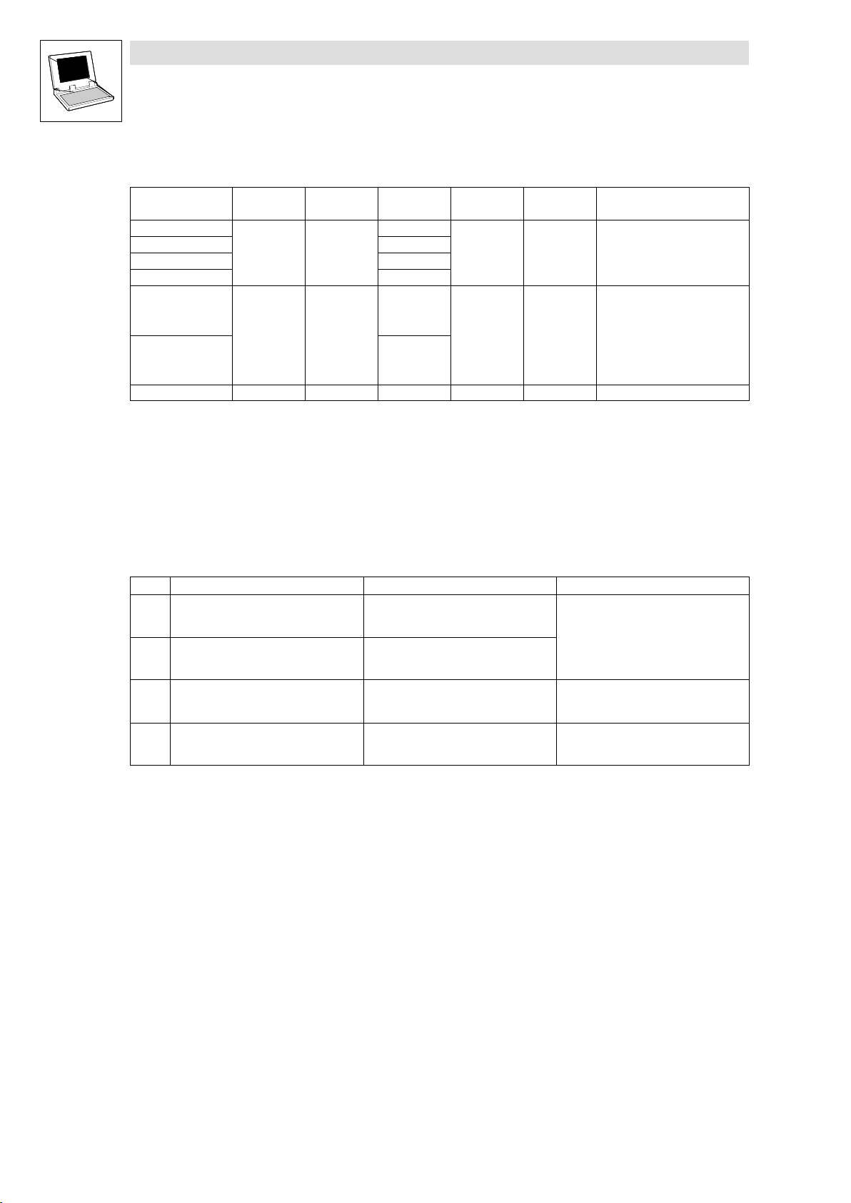
User data
The 4 first bytes of the received 8 bytes of user data are assigned to several variables of different data
types simultaneously. Thus the data can be evaluated in the PLC program as
binary information (1 bit)
quasi−analog value (16 bits)
angle information (32 bits)
according to the requirements.
Byte Variable (1 bit) Variable (16 bits) Variable (32 bits)
1, 2 AIF2_bInB0_b
...
AIF2_bInB15_b
3, 4 AIF2_bInB16_b
...
AIF2_bInB31_b
5, 6
AIF2_nInW1_a
AIF2_dnInD1_p
AIF2_nInW2_a
AIF2_nInW3_a
7, 8
AIF2_nInW4_a
2−8
9300 Servo PLC EN 5.0
L
Page 23

9300 Servo PLC
System blocks
2.2 AIF2_IO_AutomationInterface (node number 42)
2.2.2 Outputs_AIF2
This SB is used as an interface for output signals (e.g. setpoints/actual values) to attached fieldbus
modules (e.g. INTERBUS, PROFIBUS−DP).
The process image is
– created in the cyclic task in a fixed time interval of 10 ms.
– created in an interval task within the time set for this task.
– read at the beginning of the task and written at its end.
Tip!
Please observe the Operating Instructions for the attached fieldbus module.
Outputs_AIF2
AIF2_nOutW1_a
AIF2_bFDO0_b
...
AIF2_bFDO15_b
AIF2_nOutW2_a
AIF2_bFDO16_b
...
AIF2_bFDO31_b
AIF2_dnOutD1_p
AIF2_nOutW3_a
AIF2_nOutW4_a
16 Bit
16 binary
signals
16 Bit
16 binary
signals
16 Bit
LowWord
16 Bit
HighWord
16 Bit
16 Bit
Byte
Byte
Byte
Byte
Byte
Byte
Byte
Byte
1
2
3
4
5
6
7
8
Automation
Interface
Fig. 2−4 Outputs_AIF2
L
9300 Servo PLC EN 5.0
2−9
Page 24

9300 Servo PLC
System blocks
2.2 AIF2_IO_AutomationInterface (node number 42)
System variables
Variable Data type Signal type Address Display code Display
AIF2_nOutW1_a
AIF2_nOutW2_a %QW42.1
AIF2_nOutW3_a %QW42.2
AIF2_nOutW4_a %QW42.3
AIF2_bFDO0_b
... ...
AIF2_bFDO15_b %QX42.0.15
AIF2_bFDO16_b %QX42.1.0
... ...
AIF2_bFDO31_b %QX42.1.15
AIF2_dnOutD1_p Double integer Position %QD42.0
Integer Analog
Bool Binary
%QW42.0
%QX42.0.0
format
Note
User data
The first 4 bytes of the 8 bytes of user data to be sent can be written to via several variables of different
data types at the same time. Data can therefore be transferred by the PLC program as
binary information (1 bit)
quasi−analog value (16 bits)
angle information (32 bits)
according to the requirements.
Byte Variable (1 bit) Variable (16 bits) Variable (32 bits)
1, 2 AIF2_bFDO0_b
...
AIF2_bFDO15_b
3, 4 AIF2_bFDO16_b
...
AIF2_bFDO31_b
5, 6
AIF2_nOutW1_a
AIF2_dnOutD1_p
AIF2_nOutW2_a
AIF2_nOutW3_a
7, 8
AIF2_nOutW4_a
Tip!
Avoid simultaneous overwriting via different variable types to ensure data consistency.
Thus bytes 1 and 2 should only be written to
– by the variable AIF2_dnOutD1_p,
– by the variable AIF2_nOutW1_a or
– by the variables AIF2_bFDO0_b ... AIF2_bFDO15_b.
2−10
9300 Servo PLC EN 5.0
L
Page 25
9300 Servo PLC
System blocks
2.3 AIF3_IO_AutomationInterface (node number 43)
2.3 AIF3_IO_AutomationInterface (node number 43)
2.3.1 Inputs_AIF3
This SB is used as an interface for input signals (e.g. setpoints/actual values) from attached fieldbus
modules (e.g. INTERBUS, PROFIBUS−DP).
The process image is
– created in the cyclic task in a fixed time interval of 10 ms.
– created in an interval task within the time set for this task.
– read at the beginning of the task and written at its end.
Tip!
Please observe the Operating Instructions for the attached fieldbus module.
Fig. 2−5 Inputs_AIF3
Automation
Interface
Inputs_AIF3
Byte
1
Byte
2
Byte
3
Byte
4
Byte
5
Byte
6
Byte
7
Byte
8
16 Bit
16 binary
signals
16 Bit
16 binary
signals
16 Bit
LowWord
16 Bit
HighWord
16 Bit
16 Bit
AIF3_nInW1_a
AIF3_bInB0_b
...
AIF3_bInB15_b
AIF3_nInW2_a
AIF3_bInB16_b
...
AIF3_bInB31_b
AIF3_dnInD1_p
AIF3_nInW3_a
AIF3_nInW4_a
L
9300 Servo PLC EN 5.0
2−11
Page 26

9300 Servo PLC
System blocks
2.3 AIF3_IO_AutomationInterface (node number 43)
System variables
Variable Data type Signal type Address Display code Display
AIF3_nInW1_a
AIF3_nInW2_a %IW43.1
AIF3_nInW3_a %IW43.2
AIF3_nInW4_a %IW43.3
AIF3_bInB0_b
... ...
AIF3_bInB15_b %IX43.0.15
AIF3_bInB16_b %IX43.1.0
... ...
AIF3_bInB31_b %IX43.1.15
AIF3_dnInD1_p Double integer Position %ID43.0
Integer Analog
Bool Binary
%IW43.0
%IX43.0.0
format
Note
User data
The 4 first bytes of the received 8 bytes of user data are assigned to several variables of different data
types simultaneously. Thus the data can be evaluated in the PLC program as
binary information (1 bit)
quasi−analog value (16 bits)
angle information (32 bits)
according to the requirements.
Byte Variable (1 bit) Variable (16 bits) Variable (32 bits)
1, 2 AIF3_bInB0_b
...
AIF3_bInB15_b
3, 4 AIF3_bInB16_b
...
AIF3_bInB31_b
5, 6
AIF3_nInW1_a
AIF3_dnInD1_p
AIF3_nInW2_a
AIF3_nInW3_a
7, 8
AIF3_nInW4_a
2−12
9300 Servo PLC EN 5.0
L
Page 27
9300 Servo PLC
System blocks
2.3 AIF3_IO_AutomationInterface (node number 43)
2.3.2 Outputs_AIF3
This SB is used as an interface for output signals (e.g. setpoints/actual values) to attached fieldbus
modules (e.g. INTERBUS, PROFIBUS−DP).
The process image is
– created in the cyclic task in a fixed time interval of 10 ms.
– created in an interval task within the time set for this task.
– read at the beginning of the task and written at its end.
Tip!
Please observe the Operating Instructions for the attached fieldbus module.
Outputs_AIF3
AIF3_nOutW1_a
AIF3_bFDO0_b
...
AIF3_bFDO15_b
AIF3_nOutW2_a
AIF3_bFDO16_b
...
AIF3_bFDO31_b
AIF3_dnOutD1_p
AIF3_nOutW3_a
AIF3_nOutW4_a
16 Bit
16 binary
signals
16 Bit
16 binary
signals
16 Bit
LowWord
16 Bit
HighWord
16 Bit
16 Bit
Byte
Byte
Byte
Byte
Byte
Byte
Byte
Byte
1
2
3
4
5
6
7
8
Automation
Interface
Fig. 2−6 Outputs_AIF3
L
9300 Servo PLC EN 5.0
2−13
Page 28
9300 Servo PLC
System blocks
2.3 AIF3_IO_AutomationInterface (node number 43)
System variables
Variable Data type Signal type Address Display code Display
AIF3_nOutW1_a
AIF3_nOutW2_a %QW43.1
AIF3_nOutW3_a %QW43.2
AIF3_nOutW4_a %QW43.3
AIF3_bFDO0_b
... ...
AIF3_bFDO15_b %QX43.0.15
AIF3_bFDO16_b %QX43.1.0
... ...
AIF3_bFDO31_b %QX43.1.15
AIF3_dnOutD1_p Double integer Position %QD43.0
Integer Analog
Bool Binary
%QW43.0
%QX43.0.0
format
Note
User data
The first 4 bytes of the 8 bytes of user data to be sent can be written to via several variables of different
data types at the same time. Data can therefore be transferred by the PLC program as
binary information (1 bit)
quasi−analog value (16 bits)
angle information (32 bits)
according to the requirements.
Byte Variable (1 bit) Variable (16 bits) Variable (32 bits)
1, 2 AIF3_bFDO0_b
...
AIF3_bFDO15_b
3, 4 AIF3_bFDO16_b
...
AIF3_bFDO31_b
5, 6
AIF3_nOutW1_a
AIF3_dnOutD1_p
AIF3_nOutW2_a
AIF3_nOutW3_a
7, 8
AIF3_nOutW4_a
Tip!
Avoid simultaneous overwriting via different variable types to ensure data consistency.
Thus bytes 1 and 2 should only be written to
– by the variable AIF3_dnOutD1_p,
– by the variable AIF3_nOutW1_a or
– by the variables AIF3_bFDO0_b ... AIF3_bFDO15_b.
2−14
9300 Servo PLC EN 5.0
L
Page 29
9300 Servo PLC
System blocks
2.4 AIF_IO_Management (node number 161)
2.4 AIF_IO_Management (node number 161)
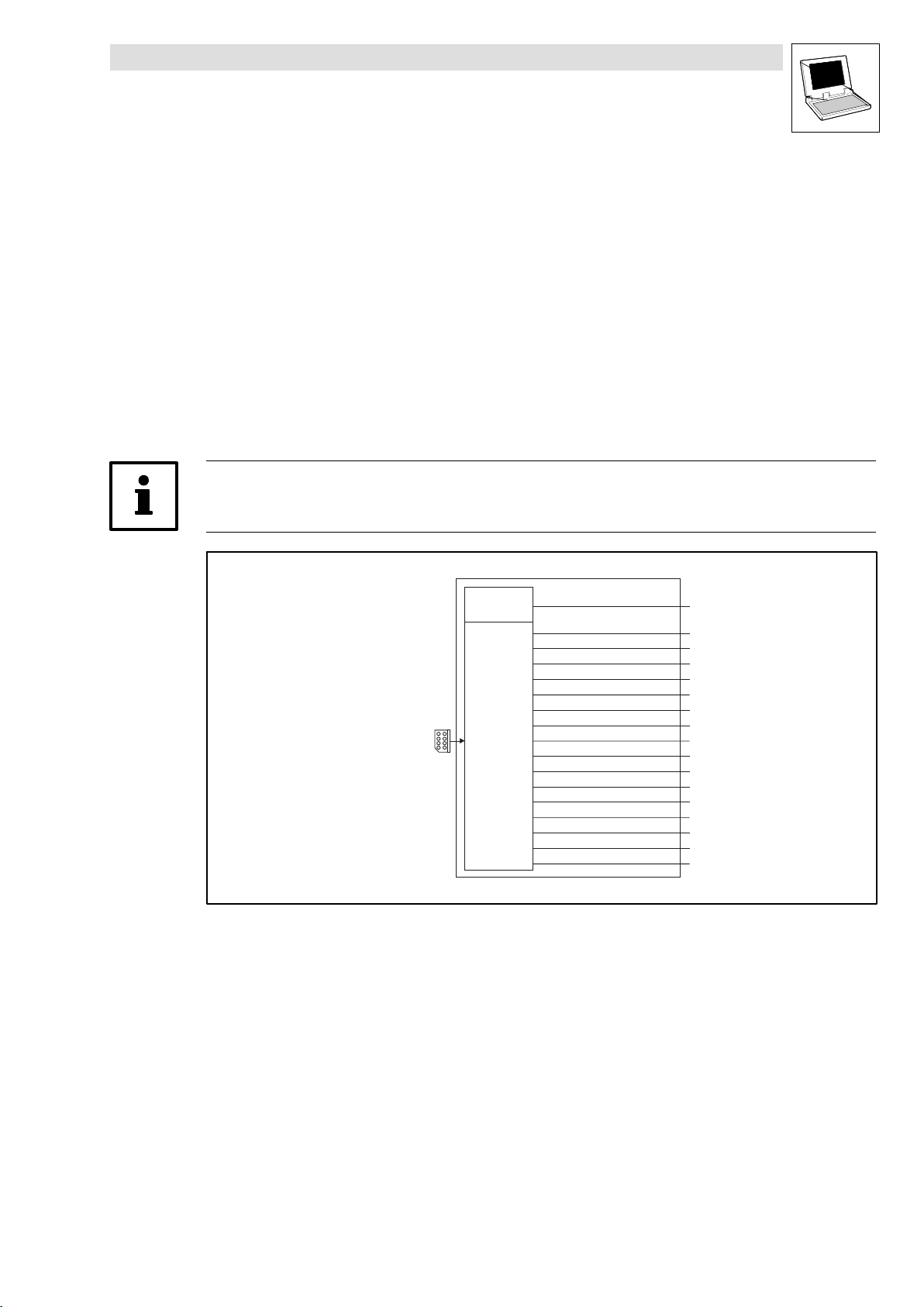
2.4.1 Inputs_AIF_Management
This SB monitors the communication of a communication module connected to the automation
interface (AIF).
In the event of an error, AIF_bCe0CommErr_b is set to TRUE and the communication error
"CE0" (LECOM no. 61) is set. The response to this can be configured under C0126 (Lenze
setting: off).
New AIF communication modules (e.g. 2133 and 2175) also use
AIF_bFieldBusStateBit0_b ... AIF_bFieldBusStateBit15_b to transfer an error number from the
communication module.
C2121 displays the status.
Tip!
Please observe the documentation for the attached communication module.
Automation
interface
Fig. 2−7 System block "Inputs_AIF_Management"
AIF
Communication
Error
AIF
Fieldbus State
Inputs_AIF_Management
AIF_bCe0CommErr_b
AIF_bFieldBusStateBit0_b
AIF_bFieldBusStateBit1_b
AIF_bFieldBusStateBit2_b
AIF_bFieldBusStateBit3_b
AIF_bFieldBusStateBit4_b
AIF_bFieldBusStateBit5_b
AIF_bFieldBusStateBit6_b
AIF_bFieldBusStateBit7_b
AIF_bFieldBusStateBit8_b
AIF_bFieldBusStateBit9_b
AIF_bFieldBusStateBit10_b
AIF_bFieldBusStateBit11_b
AIF_bFieldBusStateBit12_b
AIF_bFieldBusStateBit13_b
AIF_bFieldBusStateBit14_b
AIF_bFieldBusStateBit15_b
L
9300 Servo PLC EN 5.0
2−15
Page 30
9300 Servo PLC
System blocks
2.4 AIF_IO_Management (node number 161)
System variables
Variable Data type Signal type Address Display code Display
AIF_bCe0CommErr_b
AIF_bFieldBusStateBit0_b %IX161.1.0 Error number − bit 0
AIF_bFieldBusStateBit1_b %IX161.1.1 Error number − bit 1
AIF_bFieldBusStateBit2_b %IX161.1.2 Error number − bit 2
AIF_bFieldBusStateBit3_b %IX161.1.3 Error number − bit 3
AIF_bFieldBusStateBit4_b %IX161.1.4 Error number − bit 4
AIF_bFieldBusStateBit5_b %IX161.1.5 Error number − bit 5
AIF_bFieldBusStateBit6_b %IX161.1.6 Error number − bit 6
AIF_bFieldBusStateBit7_b %IX161.1.7 Error number − bit 7
AIF_bFieldBusStateBit8_b %IX161.1.8 Error number − bit 8
AIF_bFieldBusStateBit9_b %IX161.1.9 Error number − bit 9
AIF_bFieldBusStateBit10_b %IX161.1.10 Error number − bit 10
AIF_bFieldBusStateBit11_b %IX161.1.11 Error number − bit 11
AIF_bFieldBusStateBit12_b %IX161.1.12 Error number − bit 12
AIF_bFieldBusStateBit13_b %IX161.1.13 Error number − bit 13
AIF_bFieldBusStateBit14_b %IX161.1.14 Error number − bit 14
AIF_bFieldBusStateBit15_b %IX161.1.15 Error number − bit 15
Bool binary
%IX161.0.0 Communication error "CE0"
format
Notes
Codes
Code LCD
C0126 MONIT CE0 3
C2121 AIF: state
Possible settings
Lenze Selection
0 TRIP
2 Warning
3 Off
G
0 {dec} 255
Decimal value is bit−coded:
Bit 0 XCAN1_IN monitoring time
Bit 1 XCAN2_IN monitoring time
Bit 2 XCAN3_IN monitoring time
Bit 3 XCAN bus−off
Bit 4 XCAN operational
Bit 5 XCAN pre−operational
Bit 6 XCAN warning
Bit 7 Internally assigned
Info
Configuration for communication
error "CE0" with automation
interface
AIF−CAN: Status
Detailed information can be
found in the documentation for
the corresponding
communication module.
2−16
9300 Servo PLC EN 5.0
L
Page 31

9300 Servo PLC
System blocks
2.4 AIF_IO_Management (node number 161)
2.4.2 Outputs_AIF_Management
This SB transfers commands and messages to a fieldbus module connected to an automation
interface (AIF).
For this purpose C2120 provides a control word. The commands are specified as numbers. Some
command numbers are universally applicable for all fieldbus modules, others apply only for special
modules. The total number of commands available can amount to up to 16.
Tip!
Read the documentation for the attached fieldbus module.
Outputs_AIF_Management
AIF control word
Bit 8 … 15
AIF_wControl
Fig. 2−8 System block "Outputs_AIF_Management"
System variables
Variable Data type Signal type Address Display code Display
AIF_wControl Word %QX161.0 C2120
Codes
Code LCD
C2120 AIF: Control
Possible settings
Lenze Selection
0 No command
1 Read CAN codes + reinitialisation
2 Read XCAN codes
10 Read XCAN C2356/1 ... 4
11 Read XCAN C2357
12 Read XCAN C2375
13 Read XCAN C2376 ... C2378
14 Read XCAN C2382
255 Not assigned
Bit 7
Toggle-Bit (MSB)
Bit0…6
C2120
Note
format
Info
AIF command
L
9300 Servo PLC EN 5.0
2−17
Page 32

9300 Servo PLC
System blocks
2.5 ANALOG1_IO (node number 11)
2.5 ANALOG1_IO (node number 11)
2.5.1 Inputs_ANALOG1 (analog input)
The input is the interface for differential analog signals between terminals X6/1, 2. It can be used as
a setpoint input or as an actual value input.
X6
1
2
Fig. 2−9 Inputs_ANALOG1
System variables
C0034
Inputs_ANALOG1
AIN1_nIn_a
C0400
AIN1_bError_b
Variable Data type Signal type Address Display
code
AIN1_nIn_a Integer Analog %IW11.0 C0400 dec [%] Analog input 1
AIN1_bError_b Bool Binary %IX11.1.0 − − Only when C0034 = 1:
Display
format
Note
TRUE if I < 2 mA
Selection of master voltage/master current
C0034 can be used to set whether the input is to be used for a master voltage or a master
current:
Code LCD
C0034 Mst current 0 Selection: Master voltage/master
Possible settings
Lenze Selection
0 −10 V ... + 10 V (master voltage)
1 +4 mA ... +20 mA (master current)
2 −20 mA ... +20 mA
Info
current
Please also observe the jumper position X3 at the front of the 9300 Servo PLC in this
connection (see terminal assignment).
Use as a 4 ... 20 mA master current input
If the input is used as a master current input (C0034 =1), then AIN1_bError_b = TRUE as long
as the absolute value of the master current is < 2 mA, otherwise it is FALSE.
C0598 can be used to set the response for the case that the absolute value of the master
current is < 2 mA:
2−18
Code LCD
C0598 MONIT SD5 3 Monitoring configuration:
Possible settings
Lenze Selection
0 TRIP
2 Warning
3 Off
Info
Absolute master current value across
X6/1, 2 < 2 mA
9300 Servo PLC EN 5.0
L
Page 33

9300 Servo PLC
System blocks
2.5 ANALOG1_IO (node number 11)
Terminal assignment
Set via C0034 whether the input is to be used for a master voltage or a master current.
Set jumper bar X3 according to setting in C0034:
Stop!
Do not plug the jumper on 3−4! The PLC cannot be initialised in this case.
Terminal Use Jumper X3 Measuring range
X6/1, 2
Differential input for
master voltage
Differential input for
master current
6
4
2
6
4
2
5
3
1
5
3
1
C0034 = 0
Level:
Resolution:
Scaling:
C0034 = 1
Level:
Resolution:
Scaling:
C0034 = 2
Level:
Resolution:
Scaling:
−10 V ... +10 V
5 mV (11 bits + sign)
10 V 16384 100 %
+4 mA ... +20 mA
20 A (10 bits without sign)
+4 mA 0 0 %
+20 mA +16384 +100 %
−20 mA ... +20 mA
20 A (10 bits + sign)
20 mA 16384 100 %
2.5.2 Outputs_ANALOG1 (analog output)
The output can be used as a monitor output. Internal analog signals can be output as voltage signals
via terminal X6/62 and used, for instance, as display values or setpoints for slave drives.
AOUT1_nOut_a
Fig. 2−10 Outputs_ANALOG1
System variables
Variable Data type Signal type Address Display
AOUT1_nOut_a Integer Analog %QW11.0 C0434 dec [%] Analog output 1
Terminal assignment
Terminal Use Measuring range
X6/62 Analog output 1 (monitor 1) Level:
X6/7 Internal ground, GND −
Outputs_ANALOG1
C0434
code
Resolution:
Scaling:
X6
62
Display
format
−10 V ... +10 V (max. 2 mA)
20 mV (9 bits + sign)
10 V 16384 100 %
Note
L
9300 Servo PLC EN 5.0
2−19
Page 34

9300 Servo PLC
3
4
System blocks
2.6 ANALOG2_IO (node number 12)
2.6 ANALOG2_IO (node number 12)
2.6.1 Inputs_ANALOG2 (analog input)
The input is the interface for differential analog signals between terminals X6/3, 4.
X6
Fig. 2−11 Inputs_ANALOG2
System variables
Variable Data type Signal type Address Display
AIN2_nIn_a Integer Analog %IW12.0 C0405 dec [%] Analog input 2
Terminal assignment
Terminal Use Measuring range
X6/3, 4 Differential input for master voltage
(no effect of jumper X3)
2.6.2 Outputs_ANALOG2 (analog output)
The output can be used as a monitor output. Internal analog signals can be output as voltage signals
via terminal X6/63 and used, for instance, as display values or setpoints for slave drives.
AOUT2_nOut_a
Inputs_ANALOG2
AIN2_nIn_a
C0405
code
Level:
Resolution:
Scaling:
Outputs_ANALOG2
C0439
Display
format
−10 V ... +10 V
5 mV (11 bits + sign)
10 V 16384 100 %
X6
63
Note
Fig. 2−12 Outputs_ANALOG2
System variables
AOUT2_nOut_a Integer Analog %QW12.0 C0439 dec [%] Analog output 2
Terminal assignment
Terminal Use Measuring range
X6/63 Analog output 2 (monitor 2) Level:
X6/7 Internal ground, GND −
2−20
Variable Data type Signal type Address Display
code
Resolution:
Scaling:
9300 Servo PLC EN 5.0
Display
format
−10 V ... +10 V (max. 2 mA)
20 mV (9 bits + sign)
10 V 16384 100 %
Note
L
Page 35

9300 Servo PLC
System blocks
2.7 DCTRL_DriveControl (node number 121)
2.7 DCTRL_DriveControl (node number 121)
This SB controls the transition of the 9300 Servo PLC to certain states (e.g. TRIP, TRIP−RESET, quick
stop (QSP) or controller inhibit (CINH)).
The process image is created in the course of a fixed system task (interval: 2 ms).
DCTRL_wCAN1Ctrl
DCTRL_wAIF1Ctrl
DCTRL_bCInh1_b
DCTRL_bCInh2_b
DCTRL_bTripSet_b
DCTRL_bTripReset_b
DCTRL_bStateB0_b
DCTRL_bStateB2_b
DCTRL_b _bStateB3
DCTRL_b _bStateB4
DCTRL_bStateB5_b
DCTRL_bStateB14_b
DCTRL_bStateB15_b
C0878/1
C0878/2
C0878/3
C0878/4
16 Bit
16 Bit
C0135
C0136/1
16
C135.B3
C135.B8
C135.B9
X5/28
Bit10
Bit10
C135.B10
Bit11
Bit11
C135.B11
DCTRL_bImp_b
DCTRL_bNActEq0_b
DCTRL_bCInh_b
DCTRL_bStat1_b
DCTRL_bStat2_b
DCTRL_bStat4_b
DCTRL_bStat8_b
DCTRL_bWarn_b
DCTRL_bMess_b
Bit3
Bit3
Bit8
Bit8
Bit9
Bit9
DCTRL_DriveControl
QSP
>
1
DISABLE
>
1
>
1
CINH
TRIP-SET
>
1
TRIP-
>
1
RESET
>
1
STAT
0
1
2
3
4
5
6
7
8
9
10
11
12
13
14
15
DCTRL_bFail_b
DCTRL_bImp_b
DCTRL_bTrip_b
DCTRL_bQspIn_b
DCTRL_bRdy_b
DCTRL_bCwCCw_b
DCTRL_bNActEq0_b
DCTRL_bCInh_b
DCTRL_bStat1_b
DCTRL_bStat2_b
DCTRL_bStat4_b
DCTRL_bStat8_b
DCTRL_bWarn_b
DCTRL_bMess_b
DCTRL_bInit_b
DCTRL_bExternalFault_b
DCTRL_wFaultNumber
DCTRL_wStat
C0150
Fig. 2−13 DCTRL_DriveControl
Tip!
The SB DCTRL_DriveControl only affects the motor control and drive control of the
9300 Servo PLC, i.e. motor control/drive control and application program of the PLC are completely
independent of each other as long as the signals are not queried in the application program.
If, for instance, the motor control initiates a TRIP, the application program will not be stopped!
If, however, a TRIP is caused by a task overflow, the application program of the PLC will be
stopped as well!
L
9300 Servo PLC EN 5.0
2−21
Page 36

9300 Servo PLC
System blocks
2.7 DCTRL_DriveControl (node number 121)
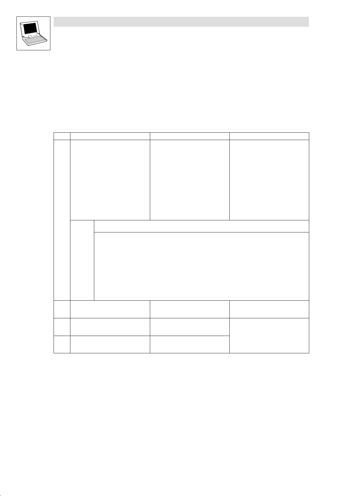
2.7.1 Inputs_DCTRL
System variables
Variables Data type Signal type Address Display
DCTRL_bFail_b
DCTRL_bImp_b %IX121.0.1 TRUE = power output stages with high
DCTRL_bTrip_b %IX121.0.2 TRUE = active fault
DCTRL_bQspIn_b %IX121.0.3 TRUE = quick stop (QSP) ^ 2−23
DCTRL_bRdy_b %IX121.0.4 TRUE = ready for operation
DCTRL_bCwCcw_b %IX121.0.5 FALSE = CW, TRUE = CCW
DCTRL_bNActEq0_b %IX121.0.6 TRUE = motor speed < C0019
DCTRL_bCInh_b %IX121.0.7 TRUE = RSP ^ 2−24
DCTRL_bStat1_b
DCTRL_bStat2_b
DCTRL_bStat4_b
DCTRL_bStat8_b
DCTRL_bWarn_b
DCTRL_bMess_b %IX121.0.13 TRUE = active message
DCTRL_bInit_b %IX121.0.14 TRUE = initialisation phase
DCTRL_bExternalFault_b %IX121.0.15 TRUE = external error ^ 2−26
DCTRL_wStat
DCTRL_wFaultNumber %IW121.2 C0168 Current error number ^ 3−8
2.7.2 Outputs_DCTRL
System variables
Bool Binary
Bool Binary
Bool Binary
Word −
Code
%IX121.0.0 TRUE = active error
%IX121.0.8
%IX121.0.9
%IX121.0.10
%IX121.0.11
%IX121.0.12 TRUE = active warning
%IW121.1 C0150
Display
Format
hex
resistance
Status signals ^ 2−25
Status word ^ 2−25
Note
Variable Data type Signal type Address Display
DCTRL_wCAN1Ctrl
DCTRL_wAIF1Ctrl %QW121.2 AIF control word
DCTRL_bCInh1_b
DCTRL_bCInh2_b
DCTRL_bTripSet_b
DCTRL_bTripReset_b
DCTRL_bStatB0_b
DCTRL_bStatB2_b
DCTRL_bStatB3_b
DCTRL_bStatB4_b
DCTRL_bStatB5_b
DCTRL_bStatB14_b
DCTRL_bStatB15_b
Word
Bool Binary
Bool Binary
%QW121.3 CAN control word
%QX121.0.1 C0878/1
%QX121.0.2 C0878/2
%QX121.0.3 C0878/3
%QX121.0.4 C0878/4
%QX121.1.0
%QX121.1.2
%QX121.1.3
%QX121.1.4
%QX121.1.5
%QX121.1.14
%QX121.1.15
Code
Display
Format
bin
Controller inhibit (CINH) ^ 2−23
TRIP−SET ^ 2−24
TRIP−RESET ^ 2−25
Status signals ^ 2−25
Note
2−22
9300 Servo PLC EN 5.0
L
Page 37

9300 Servo PLC
System blocks
2.7 DCTRL_DriveControl (node number 121)
2.7.3 Quick stop (QSP)
The QSP function is used to stop the drive independently of the selected setpoint within an adjustable
time interval.
Note!
Quick stop (QSP) will only be set if DCTRL_bQspIn_b is connected to MCTRL_bQspOut_b of
SB MCTRL_MotorControl:
DCTRL_bQspIn_b
Any Variable
OR
MCTRL_bQspOut_b
MCTRL_nHiMLim_a
MCTRL_nLoMLim_a
MCTRL_bNMSwt_b
C0907/3
C0906/4
C0906/3
C0907/2
The function can be controlled via the following 3 inputs (OR−linked):
– Control word CAN1_wDctrlCtrl of SB CAN1_IN
– Control word AIF_wDctrlCtrl of SB AIF1_IN
– Control word C0135, bit 3
C0136/1 indicates the control word C0135:
Code LCD
C0136 CTRLWORD
1 DCTRL_DriveControl
Possible settings
Lenze Selection
g
0 {hex} FFFF
Info
Control word
Hexadecimal value is bit−coded.
Speed is reduced to 0 within the deceleration time set under C0105:
Code LCD
C0105 QSP Tif 0.000 Deceleration time for quick stop (QSP)
Possible settings
Lenze Selection
0.000 {0.001 s} 999.900
Info
Referred to speed change
... 0
n
max
.
2.7.4 Operation disabled (DISABLE)
This function sets "Operation disabled (DISABLE)" in the drive, i.e. the power output stages are
inhibited and all speed/current/position controllers are reset. With "Operation disabled", the drive
cannot be started with the "Controller enable" command.
The function can be controlled via the following 3 inputs (OR−linked):
– Control word CAN1_wDctrlCtr of SB CAN1_IN
– Control word AIF_wDctrlCtrl of SB AIF1_IN
– Control word C0135, bit 8
C0136/1 indicates the control word C0135. (^ 2−23)
L
9300 Servo PLC EN 5.0
2−23
Page 38

9300 Servo PLC
System blocks
2.7 DCTRL_DriveControl (node number 121)
2.7.5 Controller inhibit (CINH)
This function sets "Controller inhibit (CINH)" in the drive, i.e. the power output stages are inhibited
and all speed/current/position controllers are reset.
The function can be controlled via the following 6 inputs (OR−linked):
– Terminal X5/28 (FALSE = controller inhibit active)
– Control word CAN1_wDctrlCtr of SB CAN1_IN
– Control word AIF_wDctrlCtrl of SB AIF1_IN
– Control word C0135, bit 9
– System variable DCTRL_bCInh1_b (TRUE = set controller inhibit)
– System variable DCTRL_bCInh2_b (TRUE = set controller inhibit)
C0136/1 indicates the control word C0135. (^ 2−23)
2.7.6 Setting TRIP (TRIP−SET)
This function sets "TRIP" in the drive and signals an "external error" (error message "EEr").
The function can be controlled via the following 4 inputs (OR−linked):
– Control word CAN1_wDctrlCtr of SB CAN1_IN
– Control word AIF_wDctrlCtrl of SB AIF1_IN
– Control word C0135, bit 10
– System variable DCTRL_bTripSet_b (TRUE = set TRIP)
C0136/1 indicates the control word C0135. (^ 2−23)
The response to TRIP can be set under C0581:
Code LCD
C0581 MONIT Eer 0 Monitoring configuration:
Possible settings
Lenze Selection
0 TRIP
1 Message
2 Warning
3 Off
Info
External error
2−24
9300 Servo PLC EN 5.0
L
Page 39

9300 Servo PLC
System blocks
2.7 DCTRL_DriveControl (node number 121)
2.7.7 Resetting TRIP (TRIP−RESET)
This function resets an active TRIP provided that the cause of malfunction is eliminated. If the cause
of malfunction is still active, there is no response.
The function can be controlled via the following 4 inputs (OR’d):
– Control word CAN1_wDctrlCtr of SB CAN1_IN
– Control word AIF_wDctrlCtrl of SB AIF1_IN
– Control word C0135, bit 11
– System variable DCTRL_bTripReset_b
Note!
The function can only be performed by the FALSE−TRUE edge of the signal resulting from the OR
operation!
A FALSE−TRUE edge cannot occur if one of the inputs is TRUE!
C0136/1 indicates the control word C0135. (^ 2−23)
2.7.8 Output of digital status signals
Via DCTRL_wStat a status word is output which consists of the signals generated from the SB
DCTRL_DriveControl and of signals from freely configurable SB inputs:
DCTRL_bStateB0_b
DCTRL_bStateB2_b
DCTRL_b _bStateB3
DCTRL_b _bStateB4
DCTRL_bStateB5_b
DCTRL_bStateB14_b
DCTRL_bStateB15_b
Fig. 2−14 Output of the status word DCTRL_wStat
DCTRL_bImp_b
DCTRL_bNActEq0_b
DCTRL_bCInh_b
DCTRL_bStat1_b
DCTRL_bStat2_b
DCTRL_bStat4_b
DCTRL_bStat8_b
DCTRL_bWarn_b
DCTRL_bMess_b
DCTRL_DriveControl
STAT
0
1
2
3
4
5
6
7
8
9
10
11
12
13
14
15
DCTRL_wStat
C0150
L
9300 Servo PLC EN 5.0
2−25
Page 40

9300 Servo PLC
System blocks
2.7 DCTRL_DriveControl (node number 121)
With C0150 you can display the status word:
Code LCD
C0150 Status word
Possible settings
Lenze Selection
g
Info
Status word DCTRL_wStat
FCODE_bC150Bit0_b ...
FCODE_bC150Bit15_b
0 {1} 65535
Decimal value is bit−coded:
Bit 00 Freely configurable 0
Bit 01 IMP (DCTRL_bImp_b)
Bit 02 Freely configurable 2
Bit 03 Freely configurable 3
Bit 04 Freely configurable 4
Bit 05 Freely configurable 5
Bit 06 n = 0 (DCTRL_bNActEq0_b)
Bit 07 RSP (DCTRL_bCInh_b)
Bit 08 Status (DCTRL_bStat1_b)
Bit 09 Status (DCTRL_bStat2_b)
Bit 10 Status (DCTRL_bStat4_b)
Bit 11 Status (DCTRL_bStat5_b)
Bit 12 Warning (DCTRL_bWarn_b)
Bit 13 Message (DCTRL_bMess_b)
Bit 14 Freely configurable 14
Bit 15 Freely configurable 15
DCTRL_bStateB0_b
DCTRL_bStateB2_b
DCTRL_bStateB3_b
DCTRL_bStateB4_b
DCTRL_bStateB5_b
DCTRL_bStateB14_b
DCTRL_bStateB15_b
The system variables DCTRL_bStat1_b ... DCTRL_bStat8_b display the status of the drive in
binary−coded form:
DCTRL_bStat8_b DCTRL_bStat4_b DCTRL_bStat2_b DCTRL_bStat1_b Status
0 0 0 0 Initialisation after connection of the supply voltage
0 0 0 1 Protection against unexpected start−up active (C0142 = 0)
0 0 1 1 Drive inhibited (controller inhibit)
0 1 1 0 Drive enabled
0 1 1 1 The triggering of a monitoring function resulted in a "message"
1 0 0 0 The triggering of a monitoring function resulted in a TRIP
1 0 1 0 The triggering of a monitoring function resulted in a FailQSP
0 = FALSE 1 = TRUE
2.7.8.1 TRIP status (DCTRL_bExternalFault_b)
If a "TRIP" is initiated in the drive (e.g. via the system variable DCTRL_bTripSet_b, C0135/bit 10 or
keypad), the system variable DCTRL_bExternalFault_b is set to TRUE.
DCTRL_bExternalFault_b is reset to FALSE as soon as the error source is reset.
2−26
9300 Servo PLC EN 5.0
L
Page 41

9300 Servo PLC
System blocks
2.7 DCTRL_DriveControl (node number 121)
2.7.9 Transfer of status/control word via AIF
If the control and/or status word of SB DCTRL_DriveControl is to be assigned to SB AIF1_IO, the
following program in the IEC1131−3 programming language IL can, for instance, be used:
LD DCTRL_wStat
ST AIF1_wDctrlStat /* writing the status word */
LD AIF1_wDctrlCtrl
ST DCTRL_wAIF1Ctrl /* writing the control word */
Tip!
The assignment of the status/control word depends on the communication module used and on the
transmission profile set (e.g. DRIVECOM).
L
9300 Servo PLC EN 5.0
2−27
Page 42

9300 Servo PLC
System blocks
2.8 DFIN_IO_DigitalFrequency (node number 21)
2.8 DFIN_IO_DigitalFrequency (node number 21)
2.8.1 Inputs_DFIN
This SB can convert a pulse current at the digital frequency input X9 into a speed value and scale it.
The transmission is very precise without offset and gain errors.
In addition, this SB provides the phase correction value DFIN_dnIncLastScan_p which is
required within the calling task for phase processing of touch probe processes.
(^ 2−33)
Fig. 2−15 DFIN_IO_DigitalFrequency
System variables
Variable Data type Signal type Address Display
DFIN_nIn_v Integer Velocity %IW21.0 C0426 dec [rpm] Value in inc/ms
DFIN_bEncFaultCable_b Bool Binary %IX21.1.0 − − TRUE = Monitoring
DFIN_bTPReceived_b Bool Binary %IX21.1.2 − − Receive touch probe (TP)
DFIN_dnIncLastScan_p Double integer Position %ID21.1 − − inc between TP and task start
X9
E5
C0427
C0425
4V
(X9/8) MONIT_SD3
MP
C0431
0
1
C0428 C0429
0
1
DFIN_IO_DigitalFrequency
C0426
DFIN_bEncFaultCable_b
TP/MP
-Ctrl
DFIN_bTPReceived_b
DFIN_dnIncLastScan_p
Code
DFIN_nIn_v
Display
Format
Note
"FaultEncCable" has been
triggered because X9/8 is not
supplied with voltage and the
digital frequency coupling is thus
interrupted.
2−28
Stop!
The digital frequency input X9 cannot be used if
you use the digital frequency output X10 (C0540 = 0, 1, 2) and
an incremental encoder/sin−cos encoder!
9300 Servo PLC EN 5.0
L
Page 43

9300 Servo PLC
System blocks
2.8 DFIN_IO_DigitalFrequency (node number 21)
Tip!
The process image is newly created for every task the SB is used in.
If DFIN_nIn_v, DFIN_dnIncLastScan_p and DFIN_bTPReceived_b are used in several tasks,
each task creates its own SB process image.
This process is different from the previous process image creation principle!
The digital frequency input X9 is dimensioned for TTL−level signals.
The input of a zero track is optional.
Configuration of the number of increments
The drive can be adapted to the connected encoder or upstream controller with digital
frequency cascade or digital frequency bus under C0425.
Code LCD
C0425 DFIN const 3 Number of increments of the encoder
Possible settings
Lenze Selection
0 256increments per revolution
1 512increments per revolution
2 1024increments per revolution
3 2048increments per revolution
4 4096increments per revolution
5 8192increments per revolution
6 16384increments per revolution
Info
input
L
9300 Servo PLC EN 5.0
2−29
Page 44

9300 Servo PLC
System blocks
2.8 DFIN_IO_DigitalFrequency (node number 21)
Configuration of the digital frequency input signal
The type of the digital frequency input signal is configured under C0427:
Code LCD
Possible settings
Info
Lenze Selection
C0427 DFIN function 0 Type of the digital frequency signal
0 2 phases
1 A = Speed / B = Direction
2 A or B = Speed or direction
C0427 = 0 (2 phases)
A
A
B
B
Z
Z
Track CW rotation CCW rotation
A leads track B by 90º
(DFIN_nIn_v = positive value)
lags behind track B by 90º
(DFIN_nIn_v = negative value)
B − −
Signal sequence with phase shift (CW rotation)
C0427 = 1 (A = Speed / B = Direction)
A
A
B
B
Z
Z
Track CW rotation CCW rotation
A transmits the speed transmits the speed
B = FALSE
(DFIN_nIn_v = positive value)
= TRUE
(DFIN_nIn_v = negative value)
Control of the direction of rotation via track B
C0427 = 2 (A or B = speed or direction)
A
A
B
B
Z
Z
Track CW rotation CCW rotation
A transmits the speed and the direction
= FALSE
of rotation
(DFIN_nIn_v = positive value)
B = FALSE transmits the speed and the direction
of rotation
(DFIN_nIn_v = negative value)
Control of the speed and the direction of rotation
via track A or track B
2−30
9300 Servo PLC EN 5.0
L
Page 45

9300 Servo PLC
System blocks
2.8 DFIN_IO_DigitalFrequency (node number 21)
Transmission function
DFIN_nIn_v + f[Hz] @
60
StrichzahlausC0425
@
15000
14
2
Example:
Input frequency = 200 kHz
C0425 = 3, this corresponds to 2048 increments/rev.
DFIN_nIn_v[rpm] + 200000Hz @
Signal adaptation
Finer resolutions can be achieved by adding a downstream FB (e.g. L_CONV from the
LenzeDrive.lib):
X9
(X9/8)
4V
MONIT_SD3
C0427
C0425
DF_IN
DFIN_nIn_v
C0426
DFIN_bEncFaultCable_b
60
+ 5859rpm
2048
nIn_a nOut_a
NNumerator
Ndenominator
L_CONV
0
TP/MP
1
E5
Fig. 2−16 Digital frequency input (DFIN_IO_DigitalFrequency) with downstream FB L_CONV for scaling
nOut_a + f[Hz] @
-Ctrl
C0428 C0429
StrichzahlausC0425
DFIN_bTPReceived_b
DFIN_dnIncLastScan_p
60
nNumerator
@
nDenominator
@
15000
14
2
L
9300 Servo PLC EN 5.0
2−31
Page 46

9300 Servo PLC
System blocks
2.8 DFIN_IO_DigitalFrequency (node number 21)
2.8.1.1 Technical data for the connection of X9
B
B
A
A
Z
Z
l = max. 50 m
Lamp control
GND
B
B
A
A
Z
Z
X9
1
1
2
2
3
3
4
4
5
5
6
6
7
7
8
8
9
9
mm
0.14
0.5
0.14
0.5
0.14
2
AWG
26
20
26
20
26
X10
1
1
2
2
3
3
4
4
5
5
6
6
7
7
8
8
9
9
Fig. 2−17 Connection of digital frequency output X10 with digital frequency input X9
Master drive
Slave drive
Cable cross−sections to be used
enable
GND
Note!
Digital frequency input (X8/X9) and digital frequency output (X10) cannot be used independently of
each other, i.e. either X8 or X9 is output to X10 (C0540 = 4, 5).
If the configuration under C0540 selects another output for X10 (C0540 = 0, 1, 2), the digital
frequency inputs X8/X9 are deactivated.
The connection is to be carried out as
shown in the wiring diagram:
Use cables which are twisted and
shielded in pairs.
Connect the shield at both ends.
Observe specified cable cross−sections.
Digital frequency input X9
Technical data
Connection: Sub−D male connector, 9−pole
Output frequency: 0 − 500 kHz
Current consumption: max. 6 mA per channel
Possible input signals: Incremental encoder with two 5 V complementary signals (TTL encoders), shifted by 90°
Encoder simulation of the master drive
Properties
Two−track with inverse 5 V signals and zero track
PIN 8 (LC) monitors the cable / the upstream drive controller:
– When PIN 8 is LOW, the "FaultEncCable" ("SD3") monitoring is triggered.
– If the monitoring is not required, this input can be connected to +5 V.
The digital frequency input is switched off with C0540 = 0, 1 or 2.
Assignment of the Sub−D male connector (X9)
PIN 1 2 3 4 5 6 7 8 9
Signal B A A +5 V GND Z Z LC B
Digital frequency output X10
See SB DFOUT_IO_DigitalFrequency. (^ 2−35)
2−32
9300 Servo PLC EN 5.0
L
Page 47

9300 Servo PLC
System blocks
2.8 DFIN_IO_DigitalFrequency (node number 21)
2.8.1.2 Touch probe (TP)
Process: The current phase value (digital frequency input value) is saved by a quick interrupt in the
operating system when a signal change occurs at the TP activating input (e.g. X5/E5).
X9
Fig. 2−18 Function chart of a TP
Time−equidistant start of an interval task
Angle signal
Touch probe configuration
Code LCD
C0428 DFIN TP sel. 0 Touch probe selection
C0429 TP delay 0 Touch probe delay
C0431 DFIN TP EDGE 0 Touch probe activation
C0427
C0425
4V
MONIT_SD3
(X9/8)
0
X5
E5
TP/MP
1
-Ctrl
C0428 C0429
Possible settings
Lenze Selection
0 Touch probe via zero pulse
1 Touch probe through digital input X5/E5
−32767 {1 inc} 32767
0 Activation with positive signal
1 Activation with negative signal
C0426
DF_IN
DFIN_nIn_v
DFIN_bEncFaultCable_b
DFIN_bTPReceived_b
DFIN_dnIncLastScan_p
nIn_a nOut_a
NNumerator
Ndenominator
L_CONV
Info
Compensation of delay times of
the TP signal source at X5/E5
For touch probe via digital input
X5/E5 (C0428 = 1)
L
9300 Servo PLC EN 5.0
2−33
Page 48

9300 Servo PLC
System blocks
2.8 DFIN_IO_DigitalFrequency (node number 21)
Functional sequence
1. The TP is activated via a signal change at the digital input X5/E5 or via a zero pulse (only if an
encoder is connected).
2. If a TP has occurred, DFIN_bTPReceived_b is set = TRUE.
3. After the start of the task, DFIN_dnIncLastScan_p indicates the number of increments [inc]
counted since the TP.
4. Then DFIN_bTPReceived_b is set = FALSE.
Note!
It is necessary that all three outputs (DFIN_nIn_v, DFIN_bTPReceived_b and
DFIN_dnIncLastScan_p) are processed in the task even if just one signal is required.
The polarity of the digital input X5/E5 configured under C0114/5 does not affect the edge
evaluation.
DFIN_nIn_v
The value DFIN_nIn_v is scaled in increments per millisecond.
(INT) 16384 corresponds to 15000 rpm. See chapter 1.2.7, "Signal types and scalings".
For every task in which DFIN_nIn_v is used the operating system creates an individual
integrator that is reset after every start of the task (task−internal process image).
For a safe TP generation, DFIN_nIn_v must not be used in the PLC_PRG.
Example (DFIN_nIn_v in a 10 ms task):
When the 10 ms task starts, the value of the integrator is stored in a local area of the task and
the integrator is reset. The value in the local area gives an average value in increments per 1
ms.
If a position value is to be derived from this value, then it must be multiplied by
SYSTEM_nTaskInterval / 4 to get the result in increments per 10 ms, as in the example.
Example: In a 1−ms task, SYSTEM_nTaskInterval has the value 4 (4 x 250 s = 1 ms).
In the Lenze FBs this process is already implemented.
2.8.1.3 Encoder cable monitoring ("FaultEncCable")
PIN 8 (LC) of the digital frequency input X9 monitors the cable / the upstream drive controller:
When PIN 8 is LOW, the "FaultEncCable" ("SD3") monitoring is triggered and the system
variable DFIN_bEncFaultCable_b is set to TRUE.
If the monitoring is not required, this input can be connected to +5 V.
(^ 1−8)
2−34
9300 Servo PLC EN 5.0
L
Page 49

9300 Servo PLC
System blocks
2.9 DFOUT_IO_DigitalFrequency (node number 22)
2.9 DFOUT_IO_DigitalFrequency (node number 22)
2.9.1 Inputs_DFOUT / Outputs_DFOUT
This SB converts internal speed signals into frequency signals and outputs them to X10.
The transmission is very precise with the remainder being considered (no offset and gain
errors).
DFOUT_nOut_v DFOUT_nIn_v
X7
X9
X8
Fig. 2−19 Digital frequency output (DF_OUT)
System variables
Variable Data type Signal type Address Display
DFOUT_nOut_v Integer Velocity %QW22.0 C0547
DFOUT_nIn_v Integer Velocity %IW22.0 − −
C0540
DFOUT_IO_DigitalFrequency
C0030
C0540
C1799
0
1
2
4
5
C0549
C0547
n
ma x
CTRL
C0545
Code
C0540
0
1
2
4
5
Display
Format
X10
Note
dec [%]
C0549
dec [rpm]
L
Tip!
The process image is newly created for every task the SB is used in.
If DFOUT_nIn_v and DFOUT_nOut_v are used in several tasks, an own process image of the
SB is created for each of these tasks.
This process is different from the previous process image creation principle!
The signals of the digital frequency output X10 are TTL−compatible.
The output signal corresponds to the simulation of an incremental encoder:
– Track A, track B and the zero track (if necessary) as well as the corresponding inverted
tracks are output with tracks shifted by 90°.
9300 Servo PLC EN 5.0
2−35
Page 50

9300 Servo PLC
System blocks
2.9 DFOUT_IO_DigitalFrequency (node number 22)
Configuration of the digital frequency output signal
The type of the digital frequency output signal is configured under C0540:
Code LCD
C0540 Function 2 Digital frequency output: Function
Possible settings
Lenze Selection
Info
X9 is inhibited if 0, 1, or 2 have
been selected.
DFOUT_nIn_v = 0 if 4 or 5 have
been selected.
The input signals are buffered
electrically.
0 DFOUT_nOut_v as %
1 DFOUT_nOut_v as rpm
2 Incremental encoder simulation + zero pulse
4 X9 is output on X10
5 X8 is output on X10
C0540 = 0 Output of an analog signal
Function The input signal DFOUT_nOut_v is interpreted as an analog signal [%] and is output as a frequency signal on the
Scaling 100 % (INT)16384 C0011 (n
Transmission function
Example
digital frequency output X10.
f[Hz] + DFOUT_nOut_v[%] @
DFOUT_nIn_v + f[Hz] @
DFOUT_nOut_v = 50 %
max)
StrichzahlausC0030
100
60
Strichzahl aus C0030
@
@
14
2
15000
C0011(n
60
max
)
C0030 = 3, this corresponds to a number of increments of 2048 increments/revolution
C0011 = 3000 rpm
2048
f[Hz] + 50% @
C0540 = 1 Output of a speed signal
Function The input signal DFOUT_nOut_v is interpreted as a speed signal [rpm] and is output as a frequency signal on the
Scaling 15000 rpm (INT)16384
Transmission function
Example
digital frequency output X10.
f[Hz] + DFOUT_nOut_v[rpm] @
DFOUT_nOut_v = 3000 rpm
100
3000
@
+ 51200Hz
60
Strichzahl aus C0030
60
C0030 = 3, this corresponds to a number of increments of 2048 increments/revolution
f[Hz] + 3000rpm @
C0540 = 2 Encoder simulation of the resolver with zero track in resolver position
Function The function is used if a resolver is connected to X7.
2048
60
+ 102400Hz
The encoder constant for the output X10 is set under C0030.
The output of the zero pulse referring to the rotor depends on how the resolver is attached to the motor.
The zero pulse can be shifted by +360 ° under C0545 (65536 inc = 360 °).
C0540 = 4 Direct output of X9
Function Use of X9 as a digital frequency input.
The input signal at X9 is electrically amplified and is directly output to X10.
The signals depend on the assignment of input X9.
C0030 and C0545 have no function.
The zero track is only output if it is also connected to X9.
C0540 = 5 Direct output of X8
Function Use of X8 as an input for incremental encoders or sin/cos encoders.
The input signal at X8 is electrically amplified and is directly output to X10.
The signals depend on the assignment of input X8.
C0030 and C0545 have no function.
The zero track is only output if it is also connected to X8.
2−36
9300 Servo PLC EN 5.0
L
Page 51

9300 Servo PLC
System blocks
2.9 DFOUT_IO_DigitalFrequency (node number 22)
Configuration of the encoder constant
The encoder constant of the encoder simulation can be set under C0030:
Code LCD
C0030 DFOUT const 3 Encoder constant
C1799 DFOUT fmax 1250 DF_OUT_DigitalFrequency:
Possible settings
Lenze Selection
0 256increments per revolution
1 512increments per revolution
2 1024increments per revolution
3 2048increments per revolution
4 4096increments per revolution
5 8192increments per revolution
6 16384increments per revolution
2.9.1.1 Technical data for the connection of X10
B
B
A
A
enable
Z
Z
l = max. 50 m
Lamp control
GND
B
B
A
A
Z
Z
X9
2
mm
1
1
0.14
2
2
3
3
4
4
0.5
5
5
6
6
0.14
7
7
0.5
8
8
0.14
9
9
X10
1
1
2
2
3
3
4
4
5
5
6
6
7
7
8
8
9
9
GND
AWG
26
20
26
20
26
Info
Maximum output frequency at X10
Note: The limitation of the maximum
output frequency at DFOUT is highly
non−linear. Hence:
C0540 1: Upstream limitation of the
value "DFOUT_nOut_v"
C0540 >1: Limitation on the motor
side via C0011.
(The non−linear resolution of the
limitation has no effect on the transfer
function of the DfOut)
The connection is to be carried out as
shown in the wiring diagram:
Use cables which are twisted and
shielded in pairs.
Connect the shield at both ends.
Observe specified cable cross−sections.
Fig. 2−20 Connection of digital frequency output X10 with digital frequency input X9
Master drive
Slave drive
Cable cross−sections to be used
Note!
Digital frequency input (X8/X9) and digital frequency output (X10) cannot be used independently of
each other, i.e. either X8 or X9 is output to X10 (C0540 = 4, 5).
If the configuration under C0540 selects another output for X10 (C0540 = 0, 1, 2), the digital
frequency inputs X8/X9 are deactivated.
L
9300 Servo PLC EN 5.0
2−37
Page 52

9300 Servo PLC
System blocks
2.9 DFOUT_IO_DigitalFrequency (node number 22)
Digital frequency output X10
Technical data
Connection: Sub−D female connector, 9−pole
Output frequency: 0 − 500 kHz
Ampacity: Max. 20 mA per channel
Load capacity: With a parallel connection, a maximum of 3 slave drives can be connected.
Properties
Two−track with inverse 5 V signals and zero track
When PIN 8 (EN) is LOW, the master drive is being initialised (e.g. if the mains was disconnected in the meantime).
The slave drive can thus monitor the master.
Assignment of the Sub−D connector (X10)
PIN 1 2 3 4 5 6 7 8 9
Signal B A A +5 V GND Z Z EN B
With a series connection, any number of slave drives can be connected.
A
A
B
B
Z
Z
Signal sequence with phase shift (CW rotation)
Track CW rotation CCW rotation
A leads track B by 90º
(DFIN_nIn_v = positive value)
B − −
lags behind track B by 90º
(DFIN_nIn_v = negative value)
Note!
The digital frequency output X10 has a system−dependent delay time Td which can be calculated
using the following formula:
= Task cycle time (process image cycle) − 1 ms
T
d
Example: If DFOUT_nOut_v is written to in a "10−ms task", the signal at X10 has a delay time T
9 ms (10 ms − 1 ms).
Digital frequency input X9
See SB DFIN_IO_DigitalFrequency. (^ 2−28)
of
d
2−38
9300 Servo PLC EN 5.0
L
Page 53

9300 Servo PLC
System blocks
2.10 DIGITAL_IO (node number 1)
2.10 DIGITAL_IO (node number 1)
2.10.1 Inputs_DIGITAL (digital inputs)
This SB reads in the signals at the terminals X5/E1 ... E5 and conditions them.
Fig. 2−21 Inputs_DIGITAL
System variables
Variable Data type Signal type Address Display
DIGIN_bCInh_b
DIGIN_bIn1_b %IX1.0.1
DIGIN_bIn2_b %IX1.0.2
DIGIN_bIn3_b %IX1.0.3
DIGIN_bIn4_b %IX1.0.4
DIGIN_bIn5_b %IX1.0.5
Electrical data of the input terminals
Terminal Use Measuring range
X5/28 Controller enable (RFR)
X5/E1
X5/E2
X5/E3
X5/E4 TP signal, actual motor speed
X5/E5 TP signal
X5/39 Ground (GND) of digital inputs and outputs
The terminal polarity of the inputs X5/E1 ... E5 can be configured under C0114:
Bool Binary
Interrupt−capable
Touch−probe−capable
1
2
X7 (resolver), X8 (encoder)
X9 (digital frequency input)
Inputs_DIGITAL
X5
28
E1
E2
E3
E4
E5
DCTRL-X5/28
DIGIN_bCInh_b
C0443
DIGIN_bIn1_b
DIGIN_bIn2_b
DIGIN_bIn3_b
DIGIN_bIn4_b
DIGIN_bIn5_b
code
Display
format
Note
C0114/1...5
0
1
1
%IX1.0.0 − − Controller inhibit (CINH) acts
directly on the DCTRL control.
C0443 bin
Freely
assignable
LOW level:
HIGH level:
Input current:
1
Response time of the interrupt task: < 250 s
2
Use of X5/E1 ... E3 as a touch probe input:
0 ... +4 V
+13 ... +30 V
8 mA per input (at 24 V)
See "Function library LenzeTpDrv.lib" manual
L
Code LCD
Possible settings
Info
Lenze Selection
C0114 DIGIN pol Terminal polarity
0 HIGH active
1 LOW active
1 1 X5/E1
2 1 X5/E2
3 0 X5/E3
4 0 X5/E4
5 0 X5/E5
9300 Servo PLC EN 5.0
2−39
Page 54

9300 Servo PLC
System blocks
2.10 DIGITAL_IO (node number 1)
2.10.2 Outputs_DIGITAL (digital outputs)
This SB conditions the digital signals and outputs them at terminals X5/A1 ... A4.
Fig. 2−22 Outputs_DIGITAL
System variables
Variable Data type Signal type Address Display
DIGOUT_bOut1_b
DIGOUT_bOut2_b
DIGOUT_bOut3_b
DIGOUT_bOut4_b %QX1.0.3 C0444/4
Electrical data of the output terminals
Terminal Use Measuring range
X5/A1
X5/A2
X5/A3
X5/A4
X5/39 Ground (GND) of digital inputs and outputs
The terminal polarity of the outputs X5/A1 ... A4 can be configured under C0118:
Bool Binary
Freely assignable
DIGOUT_bOut1_b
DIGOUT_bOut2_b
DIGOUT_bOut3_b
DIGOUT_bOut4_b
Outputs_DIGITAL
C0118/1...4
0
1
1
C0444/1...4
code
%QX1.0.0 C0444/1
%QX1.0.1 C0444/2
%QX1.0.2 C0444/3
LOW level:
HIGH level:
Output current:
Delay times:
X5
A1
A2
A3
A4
Display
Note
format
bin
0 ... +4 V
+13 ... +30 V
Max. 50 mA per output
(external resistance 480 at 24 V)
300 s with rising edge
100 s with falling edge
2−40
Code LCD
Possible settings
Info
Lenze Selection
C0118 DIGOUT pol Terminal polarity
0 HIGH active
1 LOW active
1 0 X5/A1
2 0 X5/A2
3 0 X5/A3
4 0 X5/A4
9300 Servo PLC EN 5.0
L
Page 55

9300 Servo PLC
System blocks
2.11 FCODE_FreeCode (node number 141)
2.11 FCODE_FreeCode (node number 141)
At Lenze, controller parameters are called codes. The PLC can be adapted to your application
without additional programming by changing codes.
This SB provides several variables for directly reading out the assigned "free" codes of the PLC and
for processing them in the PLC program.
FCODE_FreeCodes
C0017
C0026/1
C0026/2
C0027/1
C0027/2
C0032
C0037
C0108/1
C0108/2
C0109/1
C0109/2
C0141
C0250
C0471
C0472/1...20
C0473/1...10
C0474/1...5
C0475/1
C0475/2
C0135
rpm TO INT
%TOINT
INT
rpm TO INT
%TOINT
BOOL
DWORD
TO
BIT/BOOL
%TOINT
INT
DINT
INT
16 Bit
FCODE_nC17_a
FCODE_nC26_1_a
FCODE_nC26_2_a
FCODE_nC27_1_a
FCODE_nC27_2_a
FCODE_nC32_a
FCODE_nC37_a
FCODE_nC108_1_a
FCODE_nC108_2_a
FCODE_nC109_1_a
FCODE_nC109_2_a
FCODE_nC141_a
FCODE_bC250_b
FCODE_bC471Bit0_b
FCODE_bC471Bit31_b
FCODE_nC472_1_a
FCODE_nC472_20_a
FCODE_nC473_1_a
FCODE_nC473_10_a
FCODE_dnC474_1_p
FCODE_dnC474_5_p
FCODE_nC475_1_v
FCODE_nC475_2_v
FCODE_bC135Bit0_b
FCODE_bC135Bit15_b
...
...
...
...
...
Fig. 2−23 FCODE_FreeCodes
The PLC codes listed in the boxes ( ) on the left−hand side are assigned to the variables
listed on the right−hand side.
Code values are converted into variable values according to a fixed scaling routine.
In the code table, you can find the options that can be set and the Lenze settings. (^ 3−20)
Example
You can enter a percentage value [%] in PLC code C0472/1 (e.g. via the keypad). This value is directly
assigned to the variable FCODE_nC472_1_a (data type "integer") via a fixed scaling routine and can
be processed in the PLC program.
L
9300 Servo PLC EN 5.0
2−41
Page 56

9300 Servo PLC
System blocks
2.11 FCODE_FreeCode (node number 141)
System variables
Variable Data type Signal type Address Display
FCODE_nC17_a
FCODE_nC26_1_a
FCODE_nC26_2_a
FCODE_nC27_1_a
FCODE_nC27_2_a
FCODE_nC32_a
FCODE_nC37_a
FCODE_nC108_1_a
FCODE_nC108_2_a
FCODE_nC109_1_a
FCODE_nC109_2_a
FCODE_nC141_a
FCODE_bC250_b Bool Binary %IX141.13.0 − − Default = 0
FCODE_bC471Bit0_b
...
FCODE_bC471Bit15_b
FCODE_bC471Bit16_b
...
FCODE_bC471Bit31_b
FCODE_nC472_1_a
...
FCODE_nC472_20_a
FCODE_nC473_1_a
...
FCODE_nC473_10_a
FCODE_dnC474_1_p
...
FCODE_dnC474_5_p
FCODE_nC475_1_v
FCODE_nC475_2_v
FCODE_bC135Bit0_b
...
FCODE_bC135Bit15_b
Integer Analog
Bool Binary
Integer Analog
Integer Analog
Double integer Position
Integer Velocity
Bool Binary
%IW141.0
%IW141.2 Default = 0.00 %
%IW141.3 Default = 0.00 %
%IW141.4 Default = 100.00 %
%IW141.5 Default = 100.00 %
%IW141.6 Default = 1
%IW141.7 Default = 0 rpm
%IW141.8 Default = 100.00 %
%IW141.9 Default = 100.00 %
%IW141.10 Default = 0.00 %
%IW141.11 Default = 0.00 %
%IW141.12 Default = 0.00 %
%IX141.14.0
...
%IX141.14.15
%IX141.15.0
...
%IX141.15.15
%IW141.16
...
%IW141.35
%IW141.36
...
%IW141.45
%ID141.23
...
%ID141.27
%IW141.56
%IW141.57
%IX141.58.0
...
%IX141.58.15
code
− −
− − Default = 0
− −
− −
− − Default = 0
− − Default = 0
− − Default = 0
Display
format
Default = 50 rpm
Default = 0.00 %
C0472/3 = 100.00 %
Default = 0
C0473/1, 2 = 1
Note
2−42
9300 Servo PLC EN 5.0
L
Page 57

9300 Servo PLC
System blocks
2.11 FCODE_FreeCode (node number 141)
Note!
The free code C0470 is stored under the same memory address as C0471 and can thus be read out
via the variables FCODE_bC471Bit0_b ... FCODE_bC471Bit31_b assigned to code C0471.
Unlike code C0471, which can contain a 32−bit value, code C0470 is divided into 4 subcodes with
8 bits each:
Code LCD
C0470 FCODE 8bit Freely configurable code (digital
1 0 C0470/1 = C0471, bit 0 ... 7
2 0 C0470/2 = C0471, bit 8 ... 15
3 0 C0470/3 = C0471, bit 16 ... 23
4 0 C0470/4 = C0471, bit 24 ... 31
C0471 FCODE 32bit 0 Freely configurable code (digital
Possible settings
Lenze Selection
0 {hex} FFFF
0 {1} 4294967296
Info
signals)
C0470 has the same memory
address as C0471.
Hexadecimal value is
bit−coded.
signals)
Variables assigned via
FCODE_FreeCodes:
FCODE_bC471Bit0_b ...
FCODE_bC471Bit31_b
C0471 has the same memory
address as C0470.
L
9300 Servo PLC EN 5.0
2−43
Page 58

9300 Servo PLC
System blocks
2.12 MCTRL_MotorControl (node number 131)
2.12 MCTRL_MotorControl (node number 131)
This SB contains the control function for the driving machine. It consists of phase control, speed
control and motor control.
MCTRL_bQspOut_b
MCTRL_nHiMLim_a
MCTRL_nLoMLim_a
MCTRL_bNMSwt_b
MCTRL_nNAdapt_a
MCTRL_bILoad_b
MCTRL_nISet_a
MCTRL_nNSet_a
C0906/1
MCTRL_nPAdapt_a
C0906/9
MCTRL_dnPosSet_p
C0908
MCTRL_nPosLim_a
MCTRL_bPosOn_b
MCTRL_nNStartmLim_a
MCTRL_nMAdd_a
MCTRL_nFldWeak_a
Resolver
X7
Encoder
X8
C0907/3
C0906/4
C0906/3
C0907/2
C0907/4
C0906/8
C0105
+
100%
-
C0254
C0906/5
C0907/1
C0906/6
C0906/2
C0906/7
C0420
C0490 C0025
C0495
0
1
2
3
4
E4
C0490
OR
C0051
0
1
C0912 C0911
1
0
1
0
0
C0011 C0497
0
1
C0042
C0050
C0070
C0909
1
0
TP/MP
-Ctrl
C0910
C0072
C0070
C0071
C0576
C0579
C0596
MONIT nErr
MONIT-NMAX
Mot temp (X7 or X8)
Terminal (T1/T2)
Heatsink temp
1
0
0
C0086
VECT_CTRL
C0006
C0022
C0075
C0076
C0077
C0078
C0081
C0084
C0085
C0087
C0088
C0089
C0090
C0091
C0111
C0575
const
C0098
const
const
const
const
150°C
C0121
DIN44081
85°C
C0122
1
C0063
C0061
UG-VOLTAGE
MONIT-Sd2
MONIT-Sd6
MONIT-Sd7
MONIT-Sd8
MONIT-OH3
MONIT-OH7
MONIT-OH8
MONIT-OH
MONIT-OH4
C0053
Imotor
C0022
C0018
PWM
C0056
MONIT-LU
C0173
MONIT-OU
const
MONIT-OC1
const
MONIT-OC2
MONIT-OC5
>1,50I
NX
C0120
MONIT-OC6
C0127
MONIT-OC8
MCTRL_bMotorTempGreaterSetValue_b
MCTRL_bMotorTempGreaterC0121_b
MCTRL_bQspIn_b
MCTRL_nNSetIn_a
MCTRL_bMMax_b
MCTRL_nMSetIn_a
MCTRL_bIMax_b
MCTRL_nIAct_a
MCTRL_nDCVolt_a
MCTRL_nMAct_a
MCTRL_wMmaxC57
MCTRL_bUnderVoltage_b
MCTRL_bOverVoltage_b
MCTRL_bShortCircuit_b
MCTRL_bEarthFault_b
MCTRL_bIxtOverload_b
MCTRL_bI2xtMotorloadOc6_b
MCTRL_bI2xtMotorloadOc8_b
MCTRL_bSpeedLoopFault_b
MCTRL_nPos_a
MCTRL_nNAct_v
MCTRL_nNAct_a
MCTRL_dnPos_p
MCTRL_bNmaxFault_b
MCTRL_nNmaxC11
MCTRL_bActTPReceived_b
MCTRL_dnActIncLastScan_p
MCTRL_bResolverFault_b
MCTRL_bSensorFault_b
MCTRL_bEncoderFault_b
MCTRL_bSinCosFault_b
MCTRL_bPtcOverTemp_b
MCTRL_bKuehlGreaterSetValue_b
MCTRL_bKuehlGreaterC0122_b
Fig. 2−24 MCTRL_MotorControl
2−44
9300 Servo PLC EN 5.0
L
Page 59

9300 Servo PLC
System blocks
2.12 MCTRL_MotorControl (node number 131)
The process image is created in the course of a fixed system task (interval: 1 ms).
Exception: MCTRL_bActTPReceived_b, MCTRL_dnActIncLastScan_p and MCTRL_nNAct_v
are read into the process input image of the task in which they are actually used.
2.12.1 Inputs_MCTRL
System variables
Variable Data type Signal type Address Display
MCTRL_bQspIn_b Bool Binary
MCTRL_nNSetIn_a Integer Analog %IW131.1 C0050 dec [%]
MCTRL_bMMax_b Bool Binary %IX131.0.2 − −
MCTRL_nMSetIn_a Integer Analog %IW131.3 C0056 dec [%]
MCTRL_bIMax_b Bool Binary %IX131.0.1 − −
MCTRL_nIAct_a
MCTRL_nDCVolt_a %IW131.6
MCTRL_nMAct_a %IW131.4
MCTRL_wMmaxC57 Word − %IW131.16 − −
MCTRL_bUndervoltage_b
MCTRL_bOvervoltage_b %IX131.0.4 Monitoring: Overvoltage
MCTRL_bShortCiruit_b %IX131.0.5 Monitoring: Short circuit
MCTRL_bEarthFault_b %IX131.0.6 Monitoring: Earth fault
MCTRL_bIxtOverload_b %IX131.9.2 Monitoring: I x t overload
MCTRL_bSpeedLoop
Fault_b
MCTRL_nPos_a Integer Analog %IW131.7 − −
MCTRL_nNAct_v Integer Velocity %IW131.8 − − Actual speed value [inc/ms]
MCTRL_nNAct_a Integer Analog %IW131.2 − −
MCTRL_dnPos_p
MCTRL_bNmaxFault_b Bool Binary %IX131.0.7 − −
MCTRL_nNmaxC11 Integer − %IW131.15 − − Display of max. speed (C0011)
MCTRL_bActTP
Received_b
MCTRL_dnActIncLast
Scan_p
Integer Analog
Bool Binary
Double
Integer
Bool Binary %IX131.0.10 − − Receive touch probe (TP)
Double
Integer
Position %ID131.5 − − Rotor position of the motor
Position %ID131.6 − − inc between TP and task start
%IX131.0.0.
0
%IW131.5
%IX131.0.3
%IX131.9.4
Code
C0042 bin
− −
− −
Display
Format
Note
TRUE = Drive carries out quick stop
(QSP)
Speed setpoint
16384 100 % n
TRUE = Speed controller operates
within the limits.
Torque setpoint
16384 100 % M
TRUE = Drive operates at current limit
C0022
Actual motor current
16384 100 % I
DC voltage
max
max
max
(C0011)
(C0057)
(C0022)
16384 1000 V
Actual torque
16384 100 % M
Display of maximum torque
(C0057) x 10
Monitoring: Undervoltage
Monitoring: Speed out of tolerance
margin
Actual phase value as an analog signal
max
(C0057)
90° 100%
Actual speed value
16384 100 % n
Monitoring: Max. system speed
exceeded
max
(C0011)
L
9300 Servo PLC EN 5.0
2−45
Page 60

9300 Servo PLC
System blocks
2.12 MCTRL_MotorControl (node number 131)
Variable NoteDisplay
MCTRL_bResolverFault_b
MCTRL_bEncoderFault_b
MCTRL_bSensorFault_b
MCTRL_bSinCosFault_b
MCTRL_bMotorTemp
GreaterSetValue_b
MCTRL_bMotorTemp
GreaterC0121_b
MCTRL_bPtcOverTemp_b
MCTRL_bKuehl
GreaterSetValue_b
MCTRL_bKueh
GreaterC0122_b
MCTRL_bRotorPosition
Fault_b
MCTRL_bMotorphase
Fail_b
MCTRL_bI2xtMotorload
Oc6_b
MCTRL_bI2xtMotorload
Oc8_b
Bool Binary
AddressSignal typeData type
%IX131.0.8
%IX131.9.1 Monitoring: Encoder error
%IX131.9.0 Monitoring: Thermal sensor error
%IX131.9.3
%IX131.0.11
%IX131.0.12
%IX131.0.13
%IX131.0.14
%IX131.0.15
%IX131.9.5
%IX131.9.6
%IX131.9.7
%IX131.9.8
Display
Code
Format
− −
Monitoring: Resolver error
Monitoring: Absolute value encoder
error
Monitoring: Motor temperature
> 150 ºC
Monitoring: Motor temperature
> C0121
Monitoring: Motor overtemperature
(PTC)
Monitoring: Heatsink temperature
> 85 ºC
Monitoring: Heatsink temperature
> C0122
Monitoring: Error during last rotor
position adjustment
Monitoring: Motor phase failure
detection
Monitoring: I2t overload
Monitoring: I2t overload
2−46
9300 Servo PLC EN 5.0
L
Page 61

9300 Servo PLC
System blocks
2.12 MCTRL_MotorControl (node number 131)
2.12.2 Outputs_MCTRL
System variables
Variable Data type Signal type Address Display
MCTRL_bQspOut_b Bool Binary %QX131.0.0 C0907/3 bin
MCTRL_nHiMLim_a
MCTRL_nLoMLim_a %QW131.3 C0906/3
MCTRL_bNMSwt_b Bool Binary %QX131.0.1 C0907/2 bin
MCTRL_nNAdapt_a Integer Analog %QW131.12 − −
MCTRL_bILoad_b Bool Binary %QX131.0.3 C0907/4 bin
MCTRL_nISet_a
MCTRL_nNSet_a %QW131.1 C0906/1 Speed setpoint
MCTRL_nPAdapt_a %QW131.8 C0906/9
MCTRL_dnPosSet_p
MCTRL_nPosLim_a Integer Analog %QW131.9 C0906/5 dec [%]
MCTRL_bPosOn_b Bool Binary %QX131.0.2 C0907/1 − TRUE = Activate phase controller
MCTRL_nNStartMLim_a
MCTRL_nMAdd_a %QW131.2 C0906/2
MCTRL_nFldWeak_a %QW131.6 C0906/7 Motor control
Integer Analog
Integer Analog
Double
Integer
Integer Analog
Position %QD131.5 C0908 dec [inc]
%QW131.4 C0906/4
%QW131.7 C0906/8
%QW131.5 C0906/6
Code
Display
Format
dec [%]
dec [%]
dec [%]
Note
TRUE = Drive carries out quick stop
(QSP)
Upper torque limitation
in % of C0057
Lower torque limitation
in % of C0057
FALSE = Speed control
TRUE = Torque control
Adaptive proportional gain (Vp) of the
speed controller
TRUE = Integral action component of
the speed controller is accepted by
MCTRL_nISet_a
Integral action component of the
speed controller
Effect of C0254 on the proportional
) in %,
gain (V
p
The absolute value (without sign) is
processed.
Deviation of set phase to actual phase
for phase controller
Effect of the phase controller
In % of N
Lower speed limit for speed limitation
Additional torque setpoint or torque
setpoint
max
(C0011)
L
9300 Servo PLC EN 5.0
2−47
Page 62

9300 Servo PLC
System blocks
2.12 MCTRL_MotorControl (node number 131)
2.12.3 Current controller
Tip!
Select a matching motor from the "Motor selection list" under C0086. This automatically sets the
correct parameters for the current controller.
The "Motor selection list" can be found in the Mounting Instructions for the 9300 Servo PLC.
To adapt the current controller to the connected machine, set the controller’s proportional gain
under C0075 and the controller’s reset time under C0076:
Code LCD
C0075 Vp curr CTRL
C0076 Tn curr CTRL
Possible settings
Lenze Selection
Proportional gain of current controller
0.00 {0.01} 15.99
Reset time of current controller (T
0.5 {0.1 ms} 2000.0
2000 ms = switched off
Info
)
(V
pi
Dependent on C0086
If C0086 is changed, the value is
reset to the assigned Lenze
setting.
Dependent on C0086
If C0086 is changed, the value is
reset to the assigned Lenze
setting.
ni
)
2−48
9300 Servo PLC EN 5.0
L
Page 63

9300 Servo PLC
System blocks
2.12 MCTRL_MotorControl (node number 131)
2.12.4 Torque setpoint / additional torque setpoint
MCTRL_nMAdd_a is − depending on the setting of MCTRL_bNMSwt_b − used as a torque setpoint
or as an additional torque setpoint.
Torque setpoint
With MCTRL_bNMSwt_b = TRUE, the torque control is active.
MCTRL_nMAdd_a acts as a torque setpoint.
The speed controllers have a monitoring effect.
The torque setpoint is selected in [%] of the max. possible torque.
– Negative values mean a torque with CCW rotation of the motor.
– Positive values mean a torque with CW rotation of the motor.
The max. possible torque is set under C0057:
Code LCD
C0057 Max torque
Additional torque setpoint
With MCTRL_bNMSwt_b = FALSE, the speed control is active.
Possible settings
Lenze Selection
g
0.0 {0.1 Nm} 500.0
Info
Maximum possible torque of the drive
configuration
Dependent on C0022, C0086
MCTRL_nMAdd_a is added to the output of the speed controller.
The limits given by the torque limitation (MCTRL_nLoMLim_a and MCTRL_nHiMLim_a) cannot
be exceeded.
The additional torque setpoint can, for instance, be used for friction compensation or to add
acceleration (dv/dt).
L
9300 Servo PLC EN 5.0
2−49
Page 64

9300 Servo PLC
System blocks
2.12 MCTRL_MotorControl (node number 131)
2.12.5 Torque limitation
Via MCTRL_nLoMLim_a and MCTRL_nHiMLim_a you can set an external torque limitation. This
means that different torques can be selected for the quadrants "driving" and "braking".
MCTRL_nHiMLim_a is the upper torque limit in [%] of the max. possible torque.
MCTRL_nLoMLim_a is the lower torque limit in [%] of the max. possible torque.
The max. possible torque is set under C0057. (^ 2−49)
Stop!
Only set positive values in MCTRL_nHiMLim_a and negative values in MCTRL_nLoMLim_a,
otherwise the speed controller may be unable to perform its intended control function. This can result
in an uncontrolled acceleration of the drive.
Tip!
If MCTRL_nHiMLim_a is not assigned (free), the upper torque limit automatically is 100 % of
the max. possible torque.
If MCTRL_nLoMLim_a is not assigned (free), the lower torque limit automatically is −100 % of
the max. possible torque.
At quick stop (QSP) the torque limitation is deactivated, i.e. the drive is operated with 100 %.
2−50
9300 Servo PLC EN 5.0
L
Page 65

9300 Servo PLC
System blocks
2.12 MCTRL_MotorControl (node number 131)
2.12.6 Maximum speed
The maximum speed (n
) is set under C0011. This value is used as a reference for the absolute and
max
relative setpoints selected for the acceleration and deceleration times and for the upper and lower
speed limits.
n
Code LCD
= 100 % (INT) 16384
max
Possible settings
Lenze Selection
C0011 Nmax 3000 Maximum speed
500 {1 rpm} 16000
Info
Reference value for the absolute and
relative setpoint selection for the
acceleration and deceleration times.
For parameterisation via interface:
Large changes in one step should
only be made when the controller
is inhibited.
Tip!
MCTRL_nNmaxC11 displays the maximum speed set under C0011.
Use this system variable for programming your own speed scalings.
Example: C0011 = 3000 rpm MCTRL_nNmaxC11 = 3000
L
9300 Servo PLC EN 5.0
2−51
Page 66

9300 Servo PLC
System blocks
2.12 MCTRL_MotorControl (node number 131)
2.12.7 Speed controller
The speed controller is designed as an ideal PID controller.
Parameter setting
By selecting a motor under C0086 the parameters are preset, making most adaptations to the
application unnecessary.
The proportional gain V
– Enter approx. 50 % of the speed setpoint (100 % = 16384 = N
– Increase C0070 until the drive becomes unstable (pay attention to motor noise)
– Reduce C0070 until the drive runs stable again.
– Reduce C0070 to approx. half the value.
can be set under C0070:
p
max
).
Code LCD
C0070 Vp speed CTRL
The reset time T
Possible settings
Lenze Selection
Proportional gain of speed controller
0.0 {0.5} 255.0
can be set under C0071:
n
Info
)
(V
pn
Dependent on C0086
If C0086 is changed, the value is
reset to the assigned Lenze
setting.
– Reduce C0071 until the drive becomes unstable (pay attention to motor noise).
– Increase C0071, until the drive runs stable again.
– Increase C0071 to approx. twice the value.
Code LCD
C0071 Tn speed CTRL
The derivative gain T
Possible settings
Lenze Selection
Reset time of speed controller (T
1.0 {0.5 ms} 600.0
>512 ms = switched off
can be set under C0072:
d
Info
Dependent on C0086
If C0086 is changed, the value is
reset to the assigned Lenze
setting.
– Increase C0072 during operation until the drive reaches an optimum control performance.
Code LCD
C0072 Td speed CTRL
Via MCTRL_nNAdapt_a the proportional gain V
Possible settings
Lenze Selection
0.0 Derivative gain of speed controller
0.0 {0.1 ms} 32.0
can be changed using the PLC program:
p
Info
(Tdn)
)
nn
2−52
Vp = MCTRL_nNAdapt_a [%] C0070
Default: MCTRL_nNAdapt_a= 100 % Vp = 100 % C0070 = C0070
9300 Servo PLC EN 5.0
L
Page 67

9300 Servo PLC
System blocks
2.12 MCTRL_MotorControl (node number 131)
Signal limitation
If the drive outputs the maximum torque, the speed controller operates within the limitation.
The drive cannot follow the speed setpoint.
MCTRL_bMMax_b is set to TRUE.
Set integral action component
To select defined starting values for the torque, the integral action component of the speed controller
can be set externally (e.g. when using the brake control).
MCTRL_bILoad_b = TRUE
– The speed controller accepts the value at MCTRL_nISet_a for its integral action component.
– The value at MCTRL_nISet_a acts as a torque setpoint for the motor control.
MCTRL_bILoad_b = FALSE
– Function is switched off.
2.12.8 Torque control with speed limitation
Set MCTRL_bNMSwt_b = TRUE to activate this function.
For limiting the speed, a second speed controller (auxiliary speed controller) is connected.
MCTRL_nMAdd_a acts as a bipolar torque setpoint.
The speed controller 1 generates the upper speed limit.
– The upper speed limit is passed to MCTRL_nNSet_a in [%] of n
(positive sign for CW direction of rotation).
max
The speed controller 2 (auxiliary speed controller) generates the lower speed limit.
– The lower speed limit is passed to MCTRL_nNStartLim_a in [%] of n
(negative sign for CCW direction of rotation).
n
is selected under C0011. (^ 2−51)
max
max
Stop!
Use
the upper speed limit only for CW rotation (positive values) and
the lower speed limit only for CCW rotation (negative values),
otherwise the drive can accelerate in an uncontrolled way!
L
9300 Servo PLC EN 5.0
2−53
Page 68

9300 Servo PLC
System blocks
2.12 MCTRL_MotorControl (node number 131)
2.12.9 Speed setpoint limitation
The speed setpoint limitation can be set under C0909:
Code LCD
C0909 speed limit
Select the speed setpoint via MCTRL_nNSet_a in [%] of n
n
is selected under C0011. (^ 2−51)
max
2.12.10 Phase controller
The phase controller is needed, i.a., to ensure phase−synchronous operation and drift−free standstill.
Parameter setting
1. Assign MCTRL_nPosSet_a to a signal source which provides the phase difference between
set phase and actual phase.
2. Define a value > 0 for MCTRL_nPosLim_a.
3. Set MCTRL_bPosOn_b = TRUE.
4. Set the gain of the phase controller > 0 via C0254.
– Before setting C0254, select a proportional gain for the speed controller as high as possible
under C0070.
– Increase C0254 during operation until the drive shows the required control performance.
(^ 2−52)
Possible settings
Lenze Selection
1 Speed setpoint limitation
1 −175 % ... +175 %
2 0 % ... +175 %
3 −175 % ... 0 %
.
max
Info
Code LCD
C0254 Vp angle CTRL
Possible settings
Lenze Selection
0.4000 Gain of angle controller (Vp)
0.0000 {0.0001} 3.9999
Info
Effect of the phase controller
The output of the phase controller is added to the speed setpoint.
If the actual phase is lagging, the drive is accelerated.
If the actual phase is leading, the drive is decelerated until the desired phase synchronisation
is achieved.
The influence of the phase controller consists of:
Phase difference multiplied by the gain V
(C0254).
p
Additional influence via an analog signal at MCTRL_nPAdapt_a.
= C0254 MCTRL_nPAdapt_a / 16384)
(V
p
Limitation of the angle controller output to MCTRL_nPosLim_a.
Limitation of the phase controller output
This value limits the maximum compensation speed of the drive in the event of large phase
differences.
2−54
9300 Servo PLC EN 5.0
L
Page 69

9300 Servo PLC
System blocks
2.12 MCTRL_MotorControl (node number 131)
2.12.11 Quick stop (QSP)
The QSP function is used to stop the drive independently of the selected setpoint within an adjustable
time interval.
The QSP function is active if MCTRL_bQsp_b is set = TRUE.
If the SB DCTRL_DriveControl is to trigger QSP, the QSP function must be programmed as
follows:
DCTRL_bQspIn_b
Any Variable
Fig. 2−25 Programming of the QSP function if SB DCTRL_DriveControl is to trigger QSP
OR
MCTRL_bQspOut_b
MCTRL_nHiMLim_a
MCTRL_nLoMLim_a
MCTRL_bNMSwt_b
Function:
If torque control is selected, it will be deactivated. The drive is controlled by the speed
controller.
Speed is reduced to 0 within the deceleration time set under C0105:
Code LCD
C0105 QSP Tif
Possible settings
Lenze Selection
0.000 Deceleration time for quick stop (QSP)
0.000 {0.001 s} 999.900
The torque limits MCTRL_nLoMLim_a and MCTRL_nHiMLim_a are deactivated, i.e. the drive is
operated with
100 %. (^ 2−50)
The phase controller is activated. If the rotor position is shifted actively, the drive generates a
torque against this displacement if
– C0254 is set non−zero,
– MCTRL_nPosLim_a is triggered with a value > 0 %.
C0907/3
C0906/4
C0906/3
C0907/2
Info
Referred to speed change
... 0
n
max
.
L
Stop!
If the field is weakened manually (MCTRL_nFldWeak_a < 100 %), the drive cannot supply the
maximum torque.
9300 Servo PLC EN 5.0
2−55
Page 70

9300 Servo PLC
System blocks
2.12 MCTRL_MotorControl (node number 131)
2.12.12 Field weakening
Adjusting the field weakening range is not required if the motor type has been set under C0086. In
this case all necessary parameters are set automatically.
The motor is operated in the field weakening range if
the output voltage of the controller exceeds the rated motor voltage set under C0090.
the controller cannot increase the output voltage with increasing speed because of the mains
voltage / DC−bus voltage.
Under C0575 you can set a factor between 1 ... 8 to limit the maximum field weakening. "8" means
that the maximum field weakening is 8−fold.
Manual field weakening
The field can be weakened manually via MCTRL_nFldWeak_a.
For maximum excitation MCTRL_nFldWeak_a must be actuated with +100 % (= 16384).
If MCTRL_nFldWeak_a is not assigned (free), the field weakening is automatically +100 %.
Stop!
The available torque is reduced by the field weakening.
2.12.13 Switching frequency changeover
The following switching frequencies can be set for the inverter under C0018:
8 kHz for power−optimised operation maximum power output of the controller, but with
audible pulse operation.
16 kHz for noise−optimised operation inaudible pulse operation of the controller, but with
reduced power output (torque).
Automatic changeover between power−optimised and noise−optimised operation.
Code LCD
C0018 fchop
Automatic switching frequency changeover
You can use the automatic switching frequency changeover if you want to operate the drive in the
noise−optimised range but the torque available in this mode is not high enough for acceleration
processes.
Possible settings
Lenze Selection
1 Switching frequency
0 16/8 kHz automatic changeover Optimum noise reduction with
1 8 kHz sine Power−optimised operation
2 16 kHz sine Noise−optimised operation
Info
automatic changeover to 8 kHz
2−56
Condition M = f(I) Function
M < M
(I
) Controller operates with 16 kHz (noise−optimised)
r16
r16
M
(I
) < M < Mr8 (Ir8) Controller switches to 8 kHz (power−optimised)
r16
r16
M > M
max8
(I
) Controller operates with 8 kHz at its current limit
max8
9300 Servo PLC EN 5.0
L
Page 71

9300 Servo PLC
System blocks
2.12 MCTRL_MotorControl (node number 131)
2.12.14 Feedback systems
The following codes can be used to configure the feedback systems for position and speed
controllers:
Code LCD
[C0420] Encoder const
[C0490] Feedback pos
[C0495] Feedback n
C0497 Nact filter
Possible settings
Lenze Selection
512 Encoder: Constant for encoder input
1 {1 inc/rev} 8192
0 Feedback system for the position
IMPORTANT
X8
controller
C0490 = 0, 1, 2 can be mixed
with C0495 = 0, 1, 2.
C0490 = 3, 4 also sets C0495 to
the same value.
0 Resolver at X7
1 Encoder TTL at X8
2 Sin/cos encoder at X8
3 Absolute value encoder ST at X8
4 Absolute value encoder MT at X8
0 Feedback system for the speed
controller
C0495 = 0, 1, 2 can be mixed
with C0490 = 0, 1, 2.
C0495 = 3, 4 also sets C0490 to
the same value.
0 Resolver at X7
1 Encoder TTL at X8
2 Sin/cos encoder at X8
3 Absolute value encoder ST (single turn) at X8
4 Absolute value encoder MT (multi turn) at X8
2.0 Actual speed value filter time constant
0.0 {0.1 ms} 50.0
0 ms = switched off
PT1
L
9300 Servo PLC EN 5.0
2−57
Page 72

9300 Servo PLC
System blocks
2.12 MCTRL_MotorControl (node number 131)
2.12.15 Touch probe (TP)
Process: The current phase value (digital frequency input value) is saved by a quick interrupt in the
operating system when a signal change occurs at the TP activating input (e.g. X5/E4).
TP
j
Fig. 2−26 Function chart of a TP
Time−equidistant start of an interval task
Angle signal
Touch probe configuration
Code LCD
C0910 TP Delay
C0911 MCTRL TP sel
C0912 MCTRL TP EDGE
The feedback system generating the zero pulse is set under C0490. (^ 2−57)
MCTRL_dnActIncLastScan_p
Possible settings
Lenze Selection
0 Touch probe delay
−32767 {1 inc} 32767
0 Touch probe selection
0 Touch probe via zero pulse
1 Touch probe through digital input X5/E4
0 Touch probe activation
0 Rising edge TP2
1 Falling edge TP2
IMPORTANT
Compensation of delay times of
the TP signal source at X5/E4
For touch probe via digital input
X5/E4
(C0911 = 1)
2−58
9300 Servo PLC EN 5.0
L
Page 73

9300 Servo PLC
System blocks
2.12 MCTRL_MotorControl (node number 131)
Function sequence
1. The TP is activated via a signal change at a digital input (X5/E1 ... E4) or via a zero pulse at the
incremental encoder input X8 or the resolver input X7.
2. If a TP has occurred, MCTRL_bActTPReceived_b is set = TRUE.
3. After the start of the task MCTRL_dnActIncLastScan_p indicates the number of increments
[inc/ms] counted since the TP.
4. Then MCTRL_bActTPReceived_b is set = FALSE.
Note!
It is necessary that all three outputs (MCTRL_nNAct_v, MCTRL_bActTPReceived_b and
MCTRL_dnActIncLastScan_p) are processed in the task even if just one signal is required.
For more detailed information about the use of the digital inputs X5/E1 ... E3 for touch probe,
please refer to the "Function library LenzeTpDrv.lib" Manual.
MCTRL_nNAct_v
The value MCTRL_nNAct_v is scaled in increments per millisecond.
(INT) 16384 corresponds to 15000 rpm. See chapter 1.2.7, "Signal types and scalings".
(^ 1−8)
For every task in which MCTRL_nNAct_v is used the operating system creates an individual
integrator that is reset after every start of the task (task−internal process image).
For a safe TP generation, MCTRL_nNAct_v must not be used in the PLC_PRG.
Example (MCTRL_nNAct_v in a 10−ms task):
When the 10−ms task starts, the value of the integrator is saved in a local area of the task and
the integrator is reset. The value in the local area gives an average value in increments per
1 ms.
If a position value is to be derived from this value, then it must be multiplied by
SYSTEM_nTaskInterval / 4 to get the result in increments per
10 ms, as in the example.
Example: In a 1−ms task SYSTEM_nTaskInterval has the value 4 (4 x 0.250s = 1 ms)
In the Lenze FBs this process is already implemented.
L
9300 Servo PLC EN 5.0
2−59
Page 74

9300 Servo PLC
System blocks
2.12 MCTRL_MotorControl (node number 131)
2.12.16 Manual adaptation of motor data
If you use a motor not listed in the selection under C0086, select a motor with similar data under
C0086 and adapt the motor data manually.
Note!
If the physical limit of the drive is considerably exceeded when a motor is configured via C0086 (e.g.:
EVS9321−EI with motor C0086=41 or C0086=42), this may cause a "No program" or "float sys−T.
error".
For more detailed information about commissioning, please refer to the Mounting Instructions for the
9300 Servo PLC!
The following codes help you to manually adapt the motor data:
Code LCD
[C0006] Op mode
C0022 Imax current
C0077 Vp field CTRL
C0078 Tn field CTRL
[C0081] Mot power
Possible settings
Lenze Selection
Operating mode of the motor control
IMPORTANT
Dependent on C0086
If C0086 is changed, the value is
reset to the assigned Lenze setting
Change of C0006 sets C0086 = 0!
ESC (Extended Speed Control):
Speed control with increased
speed control steadiness for
operation with incremental
encoder only (not resolver!).
2 Servo async Y Servo control for asynchronous
3 Servo PM−SM Y Servo control for synchronous motors
22 Servo async Servo control for asynchronous
31 ASM Y − ESC Servo control for asynchronous
32 PM−SM Y − ESC Servo control for synchronous motors
33 ASM − ESC Servo control for asynchronous
I
motors in star connection
in star connection
motors in delta connection
motors in star connection, ESC
in star connection, ESC
motors in delta connection, ESC
limit
max
Dependent on C0086
If C0086 is changed, the value is
reset to the assigned Lenze setting
(1.5 * Imotor)
0 {0.01 A} 1.50 I
0.25 Gain of field controller (VpF)
0.00 {0.01} 15.99
15.0 Reset time of field controller (TnF)
1.0 {0.5 ms} 8000.0
8000 ms = switched off
Rated motor power according to
r
nameplate
Dependent on C0086
If C0086 is changed, the value is
reset to the assigned Lenze setting
Change sets C0086 = 0
0.01 {0.01 kW} 500.00
2−60
9300 Servo PLC EN 5.0
L
Page 75

9300 Servo PLC
System blocks
2.12 MCTRL_MotorControl (node number 131)
Code IMPORTANTPossible settingsLCDCode IMPORTANT
LCD
[C0084] Mot Rs
SelectionLenze
Stator resistance of the motor
Dependent on C0086
If C0086 is changed, the value is
reset to the assigned Lenze setting
Change sets C0086 = 0
0.00 {0.01 } 100.00
[C0085] Mot Ls
Leakage inductance of the motor
Dependent on C0086
If C0086 is changed, the value is
reset to the assigned Lenze setting
Change sets C0086 = 0
0.00 {0.01 mH} 200.00
[C0087] Mot speed
Rated motor speed
Dependent on C0086
If C0086 is changed, the value is
reset to the assigned Lenze setting
Change sets C0086 = 0
300 {1 rpm} 16000
[C0088] Mot current
Rated motor current
Dependent on C0086
If C0086 is changed, the value is
reset to the assigned Lenze setting
Change sets C0086 = 0
0.5 {0.1 A} 500.0
[C0089] Mot frequency
Rated motor frequency
Dependent on C0086
If C0086 is changed, the value is
reset to the assigned Lenze setting
Change sets C0086 = 0
10 {1 Hz} 1000
[C0090] Mot voltage
Rated motor voltage
Dependent on C0086
If C0086 is changed, the value is
reset to the assigned Lenze setting
Change sets C0086 = 0
50 {1 V} 500
[C0091] Mot cos phi
Motor cos
Dependent on C0086
If C0086 is changed, the value is
reset to the assigned Lenze setting
Change sets C0086 = 0
0.50 {0.01} 1.00
C0111 Rr tune
100 % Adjustment of the rotor resistance
(Particularly recommended for
non−Lenze motors and high field
weakening.)
Adjustment in % of the rated rotor
resistance of the motor.
50.00 {0.01 %} 199.99
L
9300 Servo PLC EN 5.0
2−61
Page 76

9300 Servo PLC
System blocks
2.12 MCTRL_MotorControl (node number 131)
2.12.17 Monitoring
The 9300 Servo PLC comprises two independent sectors, the motor control and the PLC.
Schnittstellen
Systembus (CAN)
Feldbusse
Leitfrequenz
analoge/digitale I/O
Speicher
(FLASH, EEPROM, RAM)
SPS-Programm
(nach IEC 61131-3, veränderbar)
Technologiefunktionen
Betriebssystem
Antriebssteuerung
Kommunikation
CAN
3
Gleichrichter
mController
Wechselrichter
Motorregelung
DSP
Digital Signal Processor
Normmotor
Asynchronmotor
3~
Synchronmotor
mit Resolver/Encoder
SIN/COS-Geber
The motor control is provided with several monitoring functions which protect the drive from
impermissible operating conditions.
If a monitoring function is activated,
the response set for this monitoring function is triggered.
a corresponding system variable is set to TRUE as long as the trigger condition for the
monitoring function is fulfilled.
The system variables of the monitoring functions can be processed in the application program of
the PLC.
The current error number is also indicated in the variable DCTRL_wFaultNumber of the PLC program.
3
2−62
9300 Servo PLC EN 5.0
L
Page 77

9300 Servo PLC
System blocks
2.12 MCTRL_MotorControl (node number 131)
The fault memory (C0168/x) stores the error messages with an offset which indicates the type of the
response:
No. of the error message Type of response
0xxx TRIP
1xxx Message
2xxx Warning
3xxx FAIL−QSP
Example: C0168/1 = 2061
x061:
The current error (subcode 1 of C0168) is a communication error (error message "CE0"/No.
"x061") between the AIF module and the PLC.
2xxx:
The response is a warning.
Tip!
Occurring faults generally do not affect the operating ability of the PLC!
For more detailed information about the error sources detected by the PLC as well as causes
& remedies, please refer to the appendix (chapter 3.5).
(^ 3−8)
L
9300 Servo PLC EN 5.0
2−63
Page 78

9300 Servo PLC
System blocks
2.12 MCTRL_MotorControl (node number 131)
Overview of system error messages of the motor control
Error
No. Display Code TRIP Message Warning FAIL−QSP Off
x011 OC1 Short circuit MCTRL_bShortCircuit_b
x012 OC2 Earth fault MCTRL_bEarthFault_b
x015 OC5 I x t overload MCTRL_bIxtOverload_b
x016 OC6 I2 x t overload MCTRL_bI2xtMotorloadOc6_b
x018 OC8 I2 x t overload MCTRL_bI2xtMotorloadOc8_b C0606
x020 OU Overvoltage MCTRL_bOvervoltage_b
x030 LU Undervoltage MCTRL_bUndervoltage_b
x032 LP1 Motor phase failure MCTRL_bMotorphaseFail_b C0597
x050 OH Heatsink temperature (fixed) MCTRL_bKuehlGreaterSet−
x053 OH3 Motor temperature (fixed) MCTRL_bMotorTempGreater−
x054 OH4 Heatsink temperature
x057 OH7 Motor temperature (adjustable) MCTRL_bMotorTemp−
x058 OH8 Motor temperature (PTC) MCTRL_bPtcOverTemp_b C0585
x082 Sd2 Resolver error MCTRL_bResolverFault_b C0586
x086 Sd6 Thermal sensor error MCTRL_bSensorFault C0594
x087 Sd7 Absolute value encoder error 1)MCTRL_bEncoderFault_b
x088 Sd8 Absolute value encoder error 1)MCTRL_bSinCosFault_b C0580
x089 PL Error during rotor position
x190 nErr Speed out of tolerance margin MCTRL_bSpeedLoopFault_b C0579
x200 NMAX Maximum speed exceeded MCTRL_bNmaxFault_b
x: 0 = TRIP, 1 = Message, 2 = Warning, 3 = FAIL−QSP
1)
When the error has been eliminated: Deenergise the controller completely!
Monitoring function System variable
Value_b
SetValue_b
MCTRL_bKuehlGreaterC0122_b C0582
(adjustable)
GreaterC0121_b
MCTRL_bRotorPositionFault_b
adjustment
Possible responses
Lenze setting Setting possible
C0583
C0584
2−64
9300 Servo PLC EN 5.0
L
Page 79

9300 Servo PLC
System blocks
2.12 MCTRL_MotorControl (node number 131)
Response and effect on the drive
Response Effect
TRIP
TRIP active: The power outputs U, V, W are switched to high resistance.
The drive is coasting (no control!).
TRIP reset: The drive runs to its setpoint along the set ramps.
Message
The drive restarts automatically when the message is no longer present!
Message active: The power outputs U, V, W are switched to high resistance.
0.5 s The drive is coasting (no control!).
0.5 s The drive is coasting (due to internal controller inhibit!). If required, restart program.
Message reset: The drive runs to its setpoint with the maximum torque.
Warning
The drive can be destroyed as a result of deactivated monitoring functions!
The failure merely is displayed, the drive runs on in a controlled manner.
FAIL−QSP − − −
The drive is decelerated to standstill along the QSP ramp (C0105).
Off − − −
The drive can be destroyed as a result of deactivated monitoring functions!
There is no response to the failure!
Keypad display
RDY IMP FAIL
= off = on
L
9300 Servo PLC EN 5.0
2−65
Page 80

9300 Servo PLC
System blocks
2.12 MCTRL_MotorControl (node number 131)
2.12.17.1 OC1 − short−circuit monitoring
This monitoring function protects the drive controller.
Error
No. Display TRIP Message Warning FAIL−QSP Off
x011 OC1 Short circuit MCTRL_bShortCircuit_b
Monitoring function System variable
Monitoring is actuated in the event of a short circuit in the motor phases. This can also be caused
by an interturn fault in the machine.
Monitoring can also respond during power−up if an earth fault occurs.
If monitoring responds, the drive controller has to be disconnected from the mains and the
short circuit has to be eliminated.
2.12.17.2 OC2 − earth−fault monitoring
This monitoring function protects the drive controller.
Error
No. Display TRIP Message Warning FAIL−QSP Off
x012 OC2 Earth fault MCTRL_bEarthFault_b
The 9300 Servo PLC is equipped with earth−fault detection as standard.
If monitoring is actuated, the drive controller has to be disconnected from the mains and the
earth fault has to be eliminated.
Possible causes of an earth fault:
Short circuit to frame of the machine
Short circuit of a phase to the shield
Short circuit of a phase to PE
Monitoring function System variable
Possible responses
Lenze setting
Setting possible
Possible responses
Lenze setting
Setting possible
2−66
9300 Servo PLC EN 5.0
L
Page 81

9300 Servo PLC
System blocks
2.12 MCTRL_MotorControl (node number 131)
2.12.17.3 OC5 − I x t overload monitoring
Error
No. Display TRIP Message Warning FAIL−QSP Off
x015 OC5 I x t overload MCTRL_bIxtOverload_b
Monitoring function System variable
Overcurrent diagram for OC5 fault message
The following diagram shows the maximum permissible overcurrent as a function of time:
Fig. 2−27 Overcurrent diagram
The maximum permissible overcurrent is dependent on the I
I
limit sender under C0022 150 % IN:
max
Within a period of 180 s, the arithmetic mean value of the motor current may not exceed 100
% of the rated device current.
I [%]
Motor
200
150
100
75
44
10 60 120 180
max
Possible responses
Lenze setting
Setting possible
t [s]
limit set under C0022. (^ 2−60)
Example: Arithmetic mean value to curve :
I
limit set under C0022 > 150 % Ir:
max
60 s @ 150 % ) 120 s @ 75 %
180 s
+ 100 %
Within a period of 60 s, the arithmetic mean value of the motor current may not exceed 70 %
of the rated device current.
Example: Arithmetic mean value to curve :
10 s @ 200 % ) 50 s @ 44 %
60 s
The current controller load is displayed in C0064:
Code LCD
C0064 Utilization
Possible settings
Lenze Selection
g
0 {1 %} 150
+ 70 %
IMPORTANT
Controller load I x t during the last
180 seconds
C0064 >100 % trips OC5.
TRIP−RESET is only possible if
C0064 < 95 %.
L
9300 Servo PLC EN 5.0
2−67
Page 82

9300 Servo PLC
Ȣ
ǒ
Ǔ
Ȥ
System blocks
2.12 MCTRL_MotorControl (node number 131)
2.12.17.4 OC6 − I2 x t overload monitoring
The I2 × t load of the motor is continuously calculated by the controller and displayed in C0066.
2
x t monitoring is dimensioned in such a way that it is triggered after 179 s in case of a motor with
I
a thermal motor time constant of 5 minutes, a motor current of 1.5 x I
100 %.
Two adjustable trigger thresholds serve to define different responses.
Adjustable response OC8 (TRIP, warning, off).
– The response is set in C0606.
– The trigger threshold is set in C0127.
– The OC8 response can be used for advance warning.
Fixed response OC6−TRIP.
– The trigger threshold is set in C0120.
Behaviour of the I2 x t monitoring Condition
I2 x t monitoring is deactivated.
C0066 = 0 % and
I2 x t monitoring is stopped.
The current value in C0066 is frozen.
I2 x t monitoring is deactivated.
The motor utilisation is displayed in C0066.
An error message OC6 or OC8 can only be reset if the I2 × t load has exceeded the set trigger
threshold by 5 %.
and a trigger threshold of
r
When C0120 = 0 % and C0127 = 0 %, set controller inhibit.
When C0120 = 0 % and C0127 = 0 %, activate controller enable.
Set C0606 = 3 (off) and C0127 > 0 %.
Calculate release time
IMActual motor current
IrRated motor current
y C0120 or C0127
t +*(C0128) @ ln
ȡ
ȧ
1 *
I
M
I
r
y ) 1
2
@ 100
ȣ
ȧ
The thermal loading capacity of the motor is expressed by the thermal motor time constant
(C0128). The value can be obtained from the rated motor data or contact the manufacturer of
the motor.
Read release time in the diagram
Diagram for detecting the release times of a motor with a thermal motor time constant of 5 min:
2
I t [%]
120
100
50
Fig. 2−28 I2 × t monitoring: Release times with different motor currents and trigger thresholds
Imot Motor current
I
r
I2tI2t load
t Time
I=3 ×I
mot r
0
0 100 200 300 400 500 600 700 800 900
Rated motor current
I=2 ×I
mot r
I=1.5 ×I
mot r
I=1 ×I
mot r
1000
t [s]
9300std105
2−68
9300 Servo PLC EN 5.0
L
Page 83

9300 Servo PLC
System blocks
2.12 MCTRL_MotorControl (node number 131)
2.12.17.5 OU − overvoltage monitoring
This function monitors the DC bus and protects the controller.
Error
No. Display TRIP Message Warning FAIL−QSP Off
x020 OU Overvoltage MCTRL_bOvervoltage_b
Monitoring function System variable
Possible responses
Lenze setting
Setting possible
Monitoring is actuated if the DC bus voltage at the terminals +UG and −UG exceeds a switch−off
threshold dependent on C0173, and it remains active until the value falls below the respective
switch−on threshold again.
The DC−bus voltage is set under C0173:
Code LCD
[C0173] UG limit 1 Adaptation of DC−bus voltage
Possible settings
Lenze Selection
0 Mains < 400 V; with or without brake unit
1 Mains = 400 V; with or without brake unit
2 Mains = 460 V; with or without brake unit
3 Mains = 480 V; without brake unit
4 Mains = 480 V; with brake unit
IMPORTANT
thresholds
Check during commissioning and
adapt if necessary
All drive components in
interconnected drives must have
the same thresholds
The switch−off and switch−on thresholds dependent on C0173 can be gathered from the
following table:
Setting of C0173 Switch−off threshold Switch−on threshold
0 Mains < 400 V; with or without brake unit 770 V 755 V
1 Mains = 400 V; with or without brake unit 770 V 755 V
2 Mains = 460 V; with or without brake unit 770 V 755 V
3 Mains = 480 V; without brake unit 770 V 755 V
4 Mains = 480 V; with brake unit 800 V 785 V
The switch−off threshold defines the voltage level of the DC−bus voltage, at which the pulse
inhibit is activated.
L
9300 Servo PLC EN 5.0
2−69
Page 84

9300 Servo PLC
System blocks
2.12 MCTRL_MotorControl (node number 131)
Braking torque derating
Without a braking system being connected (934X power supply module or 935X braking unit), the
braking torque is automatically derated when the DC−bus voltage reaches the following value:
Schwelle für Bremsmomentreduzierung + Abschaltschwelle * OV reduce
The "OV reduce" value is set under C0172:
Code LCD
[C0172] 0V reduce 10 Threshold for activating the braking
Example:
Possible settings
Lenze Selection
0 {10 V} 100
IMPORTANT
torque derating before OU trip
C0173 = 3 Switch−off threshold = 770 V
C0172 = 10 "OV reduce" = 10 V
Schwelle für Bremsmomentreduzierung + 770 V * 10 V + 760 V
The braking torque is derated as soon as the DC−bus voltage reaches or exceeds 760 V.
Braking with active braking torque derating generates clearly audible motor noise.
Tip!
If the monitoring system responds frequently, the drive dimensioning may be inappropriate (too
much braking energy being generated).
Remedy: Use 934X power supply module or (additional) 935X braking units.
When several controllers are operated simultaneously, a DC−bus connection may be useful. In
this way the braking energy generated by one drive can be used to drive another drive. Only
the energy difference is taken from the mains.
2−70
9300 Servo PLC EN 5.0
L
Page 85

9300 Servo PLC
System blocks
2.12 MCTRL_MotorControl (node number 131)
2.12.17.6 LU − undervoltage monitoring
This function monitors the DC bus and protects the controller.
Error
No. Display TRIP Message Warning FAIL−QSP Off
x030 LU Undervoltage MCTRL_bUndervoltage_b
Monitoring function System variable
Possible responses
Lenze setting
Setting possible
The monitoring responds if the DC−bus voltage at the terminals +UG and −UG falls below a switch−off
threshold dependent on C0173 and it remains active until the corresponding switch−on threshold has
again been exceeded.
The DC−bus voltage is set under C0173 (^ 2−69).
The switch−off and switch−on thresholds dependent on C0173 can be gathered from the
following table:
Setting of C0173 Switch−off threshold Switch−on threshold
0 Mains < 400 V; with or without brake unit 285 V 430 V
1 Mains = 400 V; with or without brake unit 285 V 430 V
2 Mains = 460 V; with or without brake unit 328 V 473 V
3 Mains = 480 V; without brake unit 342 V 487 V
4 Mains = 480 V; with brake unit 342 V 487 V
The switch−off threshold defines the voltage level of the DC−bus voltage, at which the pulse
inhibit is activated.
Tip!
If the undervoltage lasts longer than 3 s or if the drive is powered up, this is entered into the fault
memory.
This can be the case if the control module is supplied externally via the terminals X5/39 and
X5/59 and the mains is switched off.
If the undervoltage has been eliminated (reconnection to the mains), the entry is not updated
in the fault memory but deleted because this is not an error but a controller status.
Undervoltages which last for less than 3 s are interpreted as a fault (e.g. power system fault) and
entered into the fault memory. In this case the fault memory is updated.
L
9300 Servo PLC EN 5.0
2−71
Page 86

9300 Servo PLC
System blocks
2.12 MCTRL_MotorControl (node number 131)
2.12.17.7 LP1 − monitoring of the motor phases
This monitoring function checks if a motor phase has failed.
Note!
This monitoring function can only be used for asynchronous motors.
When this monitoring function is activated, the calculating time available for the user is
reduced.
Error
No. Display TRIP Message Warning FAIL−QSP Off
x032 LP1 Motor phase failure MCTRL_bMotorphaseFail_b
Monitoring function System variable
Possible responses
Lenze setting
Setting possible
The monitoring limit is set under C0599.
The response is set under C0597.
Code LCD
C0597 MONIT LP1
C0599 Limit LP1
Error acknowledgement
1. Check motor cables.
2. Execute TRIP−RESET.
Possible settings
Lenze Selection
3 Configuration of motor phase
0 TRIP
2 Warning
3 Off
5 LP1 fault monitoring limit
0.01 {0.01 %} 10.00
IMPORTANT
monitoring (LP1)
2−72
9300 Servo PLC EN 5.0
L
Page 87

9300 Servo PLC
System blocks
2.12 MCTRL_MotorControl (node number 131)
2.12.17.8 OH − heatsink temperature monitoring (fixed)
This monitoring function protects the drive controller.
Error
No. Display TRIP Message Warning FAIL−QSP Off
x050 OH Heatsink temperature (fixed) MCTRL_bKuehlGreaterSet−
Monitoring function System variable
Value_b
Possible responses
Lenze setting
Setting possible
MCTRL_bKuehlGreaterSetValue_b is derived from a comparator with hysteresis. The switch−off
threshold and the hysteresis are fixed:
The switch−off threshold is 85 °C
The hysteresis is 5 K, i.e. the value for switching on again is 80 ºC.
The following causes can bring about an actuation of the monitoring process:
Cause Remedy
The ambient temperature is too high. Mount a blower in the control cabinet.
The drive controller is overloaded in the arithmetic mean, i. e. overload
and recovery phase exceed 100%.
Mount a blower in the control cabinet.
Shorten overload phase.
Use a more powerful drive controller.
L
9300 Servo PLC EN 5.0
2−73
Page 88

9300 Servo PLC
System blocks
2.12 MCTRL_MotorControl (node number 131)
2.12.17.9 OH3 − motor temperature monitoring (fixed)
This monitoring function protects the motor against overheating.
Error
No. Display TRIP Message Warning FAIL−QSP Off
x053 OH3 Motor temperature (fixed) MCTRL_bMotorTempGreater−
Monitoring function System variable
SetValue_b
Possible responses
Lenze setting
Setting possible
MCTRL_bMotorTempGreaterSetValue_b is derived from a comparator with hysteresis. The
switch−off threshold and the hysteresis are fixed:
The switch−off threshold is 150 °C
The hysteresis is 15 K, i.e. the value for switching on again is 135 ºC.
This monitoring only applies to the temperature sensor specified by Lenze as it is, for instance,
included in the Lenze standard servo motor.
The Sub−D connectors X7 or X8 are available as inputs.
Stop!
The temperature sensor may either be connected to X7 or to X8; the respective other input for the
temperature sensor must be free!
This monitoring is active in the Lenze setting and is thus triggered when you use a non−Lenze servo
motor!
The response is set under C0583:
Code LCD
C0583 MONIT OH3 Monitoring configuration: Motor
Possible settings
Lenze Selection
0 TRIP
3 Off
IMPORTANT
temperature
(Motor temperature > fixed limit
temperature)
Dependent on C0086
2−74
9300 Servo PLC EN 5.0
L
Page 89

9300 Servo PLC
System blocks
2.12 MCTRL_MotorControl (node number 131)
2.12.17.10 OH4 − heatsink temperature monitoring (adjustable)
This monitoring function protects the drive controller.
Error
No. Display TRIP Message Warning FAIL−QSP Off
x054 OH4 Heatsink temperature (adjustable) MCTRL_bKuehlGreaterC0122_b
Monitoring function System variable
Possible responses
Lenze setting
Setting possible
This monitoring function is designed as an early warning stage before final disconnection of the drive
controller by means of TRIP (OH) via the monitoring function "heatsink temperature (fixed)".
(^ 2−73)
With this function the process can be influenced to avoid a switch−off of the controller at an
unfavourable moment.
Furthermore, for instance, additional fans, which would cause an unacceptable noise in
continuous operation, can also be switched on and off.
MCTRL_bKuehlGreaterC0122_b is derived from a comparator with hysteresis.
The operating threshold is set under C0122.
Hysteresis is 5 K (fixed), i. e. monitoring is reset at 5 K below the operation threshold that has
been set.
The response is set under C0582.
Code LCD
C0122 OH4 limit
C0582 MONIT OH4
Possible settings
Lenze Selection
85 Temperature threshold for heatsink
45 {1 °C} 85
2 Configuration of monitoring
2 Warning
3 Off
IMPORTANT
temperature prewarning
"Tht > C0122" (fault OH4)
L
9300 Servo PLC EN 5.0
2−75
Page 90

9300 Servo PLC
System blocks
2.12 MCTRL_MotorControl (node number 131)
2.12.17.11 OH7 − motor temperature monitoring (adjustable)
This monitoring function monitors the process.
Error
No. Display TRIP Message Warning FAIL−QSP Off
x057 OH7 Motor temperature (adjustable) MCTRL_bMotorTemp−
Monitoring function System variable
GreaterC0121_b
Possible responses
Lenze setting
Setting possible
This monitoring function is designed as an early warning stage before final disconnection of the drive
controller by means of TRIP (OH3) via the monitoring function "motor temperature (fixed)".
(^ 2−74)
With this function the process can be influenced to avoid a switch−off of the motor at an
unfavourable moment.
Furthermore, for instance, additional fans, which would cause an unacceptable noise in
continuous operation, can be switched on and off.
MCTRL_bMotorTempGreaterC0121_bis derived from a comparator with hysteresis.
The operating threshold is set under C0121.
Hysteresis is 15 K (fixed), i. e. monitoring is reset at 15 K below the operation threshold that
has been set.
The response is set under C0584.
Code LCD
C0121 OH7 limit 150 Temperature threshold for motor
C0584 MONIT OH7 Monitoring configuration: Motor
Possible settings
Lenze Selection
45 {1 °C} 150
2 Warning
3 Off
IMPORTANT
temperature prewarning
"TMot > C0121" (fault OH7)
temperature
(Motor temperature > variable limit
temperature C0121)
Dependent on C0086
Temperature monitoring via
resolver input
2−76
9300 Servo PLC EN 5.0
L
Page 91

9300 Servo PLC
System blocks
2.12 MCTRL_MotorControl (node number 131)
2.12.17.12 OH8 − motor temperature monitoring via T1, T2
This monitoring function protects the motor.
Error
No. Display TRIP Message Warning FAIL−QSP Off
x058 OH8 Motor temperature (PTC) MCTRL_bPtcOverTemp_b
Monitoring function System variable
Possible responses
Lenze setting
Setting possible
MCTRL_bPTCOverTemp_b is derived from the digital signal across the terminals T1, T2 next to the
power terminals UVW.
The switch−off threshold and the hysteresis depend on the encoder system (DIN 44081).
The response is set under C0585:
Code LCD
C0585 MONIT OH8 3 Monitoring configuration: Motor
Possible settings
Lenze Selection
0 TRIP
2 Warning
3 Off
IMPORTANT
temperature
(Motor temperature across T1/T2 too
high)
Temperature monitoring via PTC
input
Stop!
If you use the inputs T1, T2 to protect the motor, the monitoring response should not be "Warning"
or "Off" since the motor could be damaged or destroyed in the event of more overload!
L
9300 Servo PLC EN 5.0
2−77
Page 92

9300 Servo PLC
System blocks
2.12 MCTRL_MotorControl (node number 131)
2.12.17.13 Sd2 − resolver monitoring for open circuit
This monitoring function monitors the resolver feed cable and the resolver for open circuits and
protects the motor.
Error
No. Display TRIP Message Warning FAIL−QSP Off
x082 Sd2 Resolver error MCTRL_bResolverFault_b
Monitoring function System variable
Possible responses
Lenze setting
Setting possible
Stop!
If the monitoring is switched off, the machine can reach very high speeds in the event of faults (e. g.
system cable is disconnected or not correctly screwed), which can result in the damage of the motor
and of the driven machine! The same applies if "warning" is set as a response.
For commissioning, always use the Lenze setting C0586 = 0 (TRIP).
Only use the configuration C0586 = 2 (warning) and C0586 = 3 (monitoring switched off) if
monitoring is triggered without any obvious reason (e.g. due to long cables or intense
interference injection caused by other devices). Despite faulty feedback, the pulses are
enabled.
If a fault has occurred in the actual speed detection, it is possible that the overspeed monitoring
(NMAX) does not respond as expected.
This monitoring
– is automatically activated if the resolver is selected as an actual speed value encoder under
C0025 (C0025 = 10).
– is automatically deactivated if another actual speed value encoder is selected.
The response is set under C0586:
Code LCD
C0586 MONIT SD2 0 Monitoring configuration: Resolver
Possible settings
Lenze Selection
0 TRIP
2 Warning
3 Off
IMPORTANT
error
2−78
9300 Servo PLC EN 5.0
L
Page 93

9300 Servo PLC
System blocks
2.12 MCTRL_MotorControl (node number 131)
2.12.17.14 Sd6 − motor temperature sensor monitoring
This monitoring function checks whether the motor temperature sensor supplies values within the
measuring range of −50 ... +250 °C.
If the values are out of this measuring range, monitoring is triggered.
Error
No. Display TRIP Message Warning FAIL−QSP Off
x086 Sd6 Thermal sensor error MCTRL_bSensorFault
Monitoring function System variable
The response is set under C0586:
Code LCD
C0594 MONIT SD6 Monitoring configuration: Motor
Possible settings
Lenze Selection
0 TRIP
2 Warning
3 Off
2.12.17.15 Sd7 − absolute value encoder monitoring
This monitoring function repeatedly reads in the absolute value of the encoder when the PLC is
switched on to find out if the same value is transmitted to the drive.
If a deviation > 5 % is detected at the motor shaft, the monitoring (TRIP) is actuated.
Error
No. Display TRIP Message Warning FAIL−QSP Off
x087 Sd7 Absolute value encoder error MCTRL_bEncoderFault_b
Monitoring function System variable
Possible responses
Lenze setting
Setting possible
IMPORTANT
temperature sensor error
(X7 or X8)
Dependent on C0086
Possible responses
Lenze setting
Setting possible
L
9300 Servo PLC EN 5.0
2−79
Page 94

9300 Servo PLC
System blocks
2.12 MCTRL_MotorControl (node number 131)
2.12.17.16 Sd8 − sin/cos encoder monitoring during operation
This monitoring function performs a plausibility check to find out whether the encoder is available and
the sin/cos tracks supply plausible values with regard to each other.
Error
No. Display TRIP Message Warning FAIL−QSP Off
x088 Sd8 Absolute value encoder error MCTRL_bSinCosFault_b
Monitoring function System variable
Possible responses
Lenze setting
Setting possible
The following sin/cos encoder types are supported:
– Stegmann SCS 60/70 ST 512 single−turn absolute value encoder (512 inc/rev)
– Stegmann SCM 60/70 ST 512 multi−turn absolute value encoder (512 inc/rev)
The error "Sd8" can only be reset by mains switching.
It may be necessary that the encoder has to move a few angular degrees for triggering an
error.
The response is set under C0580:
Code LCD
C0580 MONIT SD8
Possible settings
Lenze Selection
3 Monitoring configuration: Sin/cos
0 TRIP
3 Off
IMPORTANT
encoder
Note!
If the encoder is to be monitored and, especially, if synchronous machines are used, the error
response should be set to "TRIP".
For further encoder reliability, the monitoring of following errors can, for example, additionally be
activated for positioning systems. This error response should also be set to "TRIP".
Apparent errors Hidden errors
Unplugged connectors, all encoder signals open.
Single open circuit, one of the following signals is missing:
– COS A
– RefCOS A
– SIN B
– RefSIN B
– GND
– VCC
Double open circuit with the following signal pairs:
– COS A and RefCOS A
– SIN B and RefSIN B
– COS A and SIN B
– RefCOS A and RefSIN B
– or all four signals (COS A, RefCOS A, SIN B, RefSIN B) open.
Short circuits, especially between the sine and cosine signals.
Cable/encoder interferences with intermediate values
"Semi"−short circuits (> 0 Ohm)
"Semi"−interruptions (< infinite)
2−80
9300 Servo PLC EN 5.0
L
Page 95

9300 Servo PLC
System blocks
2.12 MCTRL_MotorControl (node number 131)
2.12.17.17 PL − monitoring of the rotor position adjustment
This monitoring function monitors the correct execution of the rotor position adjustment.
Note!
The PL monitoring is only activated when a synchronous machine (C0006 = 3) is selected.
Error
No. Display TRIP Message Warning FAIL−QSP Off
x089 PL Error during rotor position adjustment MCTRL_bRotorPositionFault_b
Error triggering
Monitoring function System variable
Possible responses
Lenze setting
Setting possible
If an Sd7 error occurs during the rotor position adjustment with an absolute value encoder, a
TRIP will occur after the subsequent mains switching.
If a rotor position adjustment with any encoder is aborted (e.g. by C0095 = 0 or switch−off), a
TRIP will occur.
Error acknowledgement
Note!
For acknowledging the error, a synchronous machine (C0006 = 3) must be selected.
1. Activate rotor position adjustment with C0095 = 1.
2. Execute TRIP−RESET.
3. Re−execute the rotor position adjustment with controller enable.
L
9300 Servo PLC EN 5.0
2−81
Page 96

9300 Servo PLC
System blocks
2.12 MCTRL_MotorControl (node number 131)
2.12.17.18 nErr − speed monitoring (speed out of tolerance margin)
This monitoring function compares the actual speed value supplied by the speed encoder to the
speed setpoint on the speed controller. If the difference between the two speed values exceeds the
tolerance margin set in C0576, the monitoring function is actuated.
Error
No. Display TRIP Message Warning FAIL−QSP Off
x190 nErr Speed out of tolerance margin MCTRL_bSpeedLoopFault_b
Monitoring function System variable
Possible responses
Lenze setting
Setting possible
This monitoring function can be used to evaluate the speed following behaviour of the controller.
If the system deviation exceeds a certain value, this may indicate a drive problem. In this case,
the drive cannot follow the set speed setpoint for some reason. With operational controllers,
this may be caused by mechanical blockades on the load side, or by an insufficient motor
torque.
Furthermore, this monitoring function can be used for additional speed encoder protection in
speed−controlled operation. This monitoring function thus supplements the individual encoder
monitoring functions.
Errors on the encoder system bring about an incorrect actual speed value. This usually results
in a system deviation on the speed controller that is greater than that during normal operation.
The tolerance margin is set via C0576:
The response is set via C0579:
Code LCD
C0576 nErr Window 100 Tolerance margin for speed
C0579 MONIT nErr 3 Speed monitoring configuration
Possible settings
Lenze Selection
0 {1 %} 100
0 TRIP
1 Message
2 Warning
3 Off
4 FAIL−QSP
IMPORTANT
monitoring
Referred to n
100 % = lowest monitoring
sensitivity.
max
.
2−82
Note!
If the encoder is to be monitored, set the error response to "TRIP".
To ensure that there are no false alarms, it might be necessary to adapt the setpoint/quick
stop ramps (by means of longer time intervals) to the application.
The selected tolerance margin (C0576) should be at least twice as high as the system
deviation occurring during operation. The deviation can be determined by means of
appropriate tests during commissioning.
9300 Servo PLC EN 5.0
L
Page 97

9300 Servo PLC
System blocks
2.12 MCTRL_MotorControl (node number 131)
2.12.17.19 NMAX − speed monitoring (maximum speed exceeded)
This monitoring function monitors the process.
Error
No. Display TRIP Message Warning FAIL−QSP Off
x200 NMAX Maximum speed exceeded MCTRL_bNmaxFault_b
Monitoring function System variable
Possible responses
Lenze setting
Setting possible
The monitoring responds when the current speed exceeds the upper speed limit of the system or the
double value of C0011 (n
max
).
Stop!
For active loads (e. g. hoists) ensure torque−free operation of the drive. Special
system−specific measures are required!
If the actual speed value encoder fails, the monitoring may fail to respond.
The upper system speed is set under C0596:
Code LCD
C0596 NMAX limit
Possible settings
Lenze Selection
5500 Monitoring configuration: Max. speed
0 {1 rpm} 16000
IMPORTANT
of the machine
L
9300 Servo PLC EN 5.0
2−83
Page 98

9300 Servo PLC
System blocks
2.13 MCTRL_AUX_HighResFeedback (node number 181)
2.13 MCTRL_AUX_HighResFeedback (node number 181)
High−resolution encoder
Use this SB only after consulting with Lenze!
2.13.1 Inputs_MCTRL_AUX_HighResFeedback
Variable Data type Data type Address Display
MCTRL_AUX_
dnEncoderAngle
Double
integer
Position %ID181.0 High−resolution encoder position
2.13.2 Outputs_MCTRL_AUX_HighResFeedback
Variable Data type Data type Address Display
MCTRL_AUX_
wEncoderMask
Word − %QW181.0
code
code
Display
format
Display
format
Note
Note
Mask for high−resolution encoder
position
2−84
9300 Servo PLC EN 5.0
L
Page 99

9300 Servo PLC
System blocks
2.14 STATEBUS_IO (node number 51)
2.14 STATEBUS_IO (node number 51)
The state bus is a bus system specifically designed for Lenze controllers/PLCs.
This SB can set the state bus to LOW level and thus set all nodes connected to the state bus to a
previously selected status (e.g. TRIP, quick stop (QSP) or controller inhibit (CINH)).
The SB immediately detects when a node sets the state bus to LOW level and the corresponding
control signal can be processed in the PLC program.
Fig. 2−29 STATEBUS_IO
Variable
STATEBUS_bOut_b Bool Binary %QX51.0.4 C0441 bin LOW signal output
STATEBUS_bIn_b Bool Binary %IX51.0.6 − − LOW signal detection
Every device connected to the state bus can set the state bus to LOW level (multi−master
operation).
A maximum of 20 devices (controllers/PLCs) can be networked via the state bus.
9300 Servo PLC / 932X / 933X
Data type Signal type Address Display
L2L1 L3 PE +UG -UG
VU W ST 39 ST PE 28 A4PE
STATE_BUS_bOut_b
9300 Servo PLC / 932X / 933X
+10V
1
C0441
L2L1 L3 PE +UG -UG
VU W ST 39 ST PE 28 A4PE
STATEBUS_IO
STATE_BUS_bIn_b
code
ST
ST
X5
Display
format
L2L1 L3 PE +UG -UG
9300 Servo PLC / 932X / 933X
VU W ST 39 ST PE 28 A4PE
Note
Fig. 2−30 Networking via the state bus
Stop!
Do not connect an external voltage to terminals X5/ST!
L
9300 Servo PLC EN 5.0
2−85
Page 100

9300 Servo PLC
System blocks
2.15 SYSTEM_FLAGS (system flags, node number 151)
2.15 SYSTEM_FLAGS (system flags, node number 151)
System flags are global variables which are permanently integrated into the run−time system. They
include functions that facilitate programming.
2.15.1 Inputs SYSTEM_FLAGS
The following system flags are included in the DrivePLC:
Variable Data type Address Notes
SYSTEM_bClock01Hz
SYSTEM_bClock1Hz %IX151.0.8 1.0 Hz system clock
SYSTEM_bClock10Hz %IX151.1.0 10 Hz system clock
SYSTEM_bClock0100Hz %IX151.1.8 100 Hz system clock
SYSTEM_bTogCycleTask %IX151.2.0 Toggle flag cyclic task
SYSTEM_b1LoopCyclicTask %IX151.2.8 First loop cyclic task
SYSTEM_b1LoopTask2 %IX151.3.0 First loop task ID2
SYSTEM_b1LoopTask3 %IX151.3.8 First loop task ID3
SYSTEM_b1LoopTask4 %IX151.4.0 First loop task ID4
SYSTEM_b1LoopTask5 %IX151.4.8 First loop task ID5
SYSTEM_b1LoopTask6 %IX151.5.0 First loop task ID6
SYSTEM_b1LoopTask7 %IX151.5.8 First loop task ID7
SYSTEM_b1LoopTask8 %IX151.6.0 First loop task ID8
SYSTEM_b1LoopTask9 %IX151.6.8 First loop task ID9
SYSTEM_nTaskInterval
SYSTEM_nTaskID %IW151.8 ID−number of current task
Bool
Integer
%IX151.0.0 0.1 Hz system clock
%IW151.7 Interval of current task
Tip!
The system variables are not generated in simulation mode.
SYSTEM_bClockxHz
These system flags output a fixed clock pulse with an equal pulse/pause ratio.
The flag is toggled in real time.
When you use this system flag, take care with the frequency used for polling the flag (aliasing
effect). You should use at least twice the toggle frequency.
Note!
The system flags SYSTEM_bClockxHz must not be used to trigger event−controlled tasks. Use
time−controlled tasks for this.
Example:
You would like to use the system flag SYSTEM_bClock100Hz as a clock for a counter.
The pulse/pause ratio is 5 ms/5 ms.
2−86
To avoid an aliasing effect, the counter must always be polled with an INTERVAL TASK < 5 ms.
9300 Servo PLC EN 5.0
L
 Loading...