

Page 1
BA 11.5032−EN
.=<Q
Ä.=<Qä
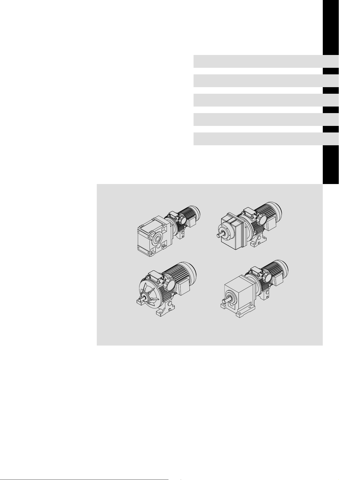
Operating Instructions
Gearbox
DISCO−Variable speed drive
l
Page 2

Product key
DISCO variable speed drive with rear−mounted gearbox − D −
Lengend for the product key
Gearbox type GST
GKS
GSS
Helical gearbox
Helical−bevel gearbox
Helical−worm gearbox
Gearbox size
Number of stages
Disco variable speed drive
Output design
A
R
Drive size Motor frame size
V
H
S
B
C
K
l
motor design
DISCO size
Solid shaft
Hollow shaft
Hollow shaft with shrink disk
Foot mounting, with centring
Foot mountin, without centring
Without foot, with centring
Without flange
With flange (through holes)
With flange (threaded holes)
2
l
BA 11.5032−EN 3.0
Page 3

DISCO variable speed drive without rear−mounted gearbox 11. 7 0 0 0.
Lengend for the product key
Product group
Product family 1
DISCO size
Free output shaft 1
0
no data
with motor
with free drive shaft
without motor
Standard
BA 11.5032−EN 3.0
l
3
Page 4
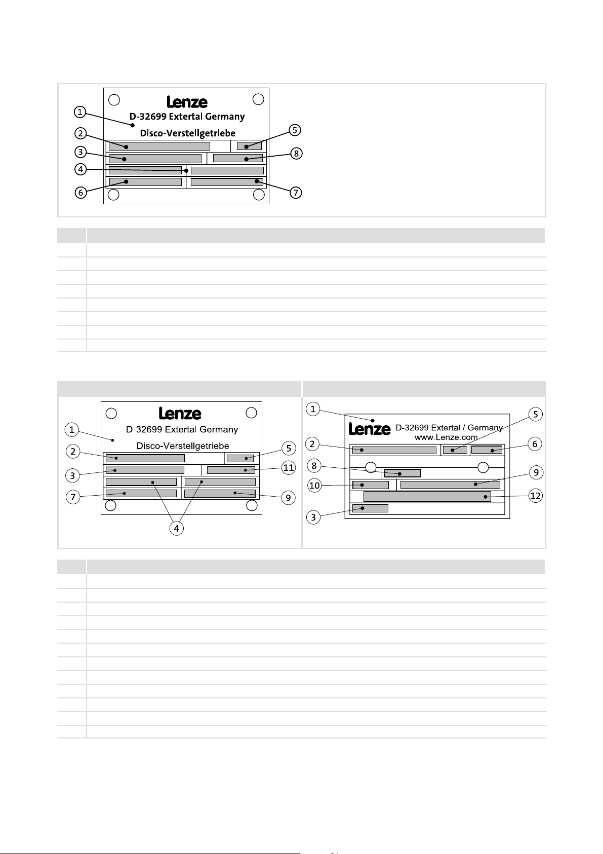
Nameplate
DISCO variable speed drive without rear−mounted gearbox
Pos. Contents
1 Production location / Name of product
2 Gearbox type
3 Order number
4 Rated speed:drive | output
5 Year of manufacture/ week of manufacture
6 Rated torque
7 Material number
8 Power
GT−DISCO−002.iso
DISCO variable speed drive with rear−mounted gearbox
DISCO nameplate Nameplate of rear−mounted gearbox
GT−DISCO−001.iso GT−DISCO−006.iso
Pos. Contents
1 Production location / Name of product
2 Gearbox type
3 Order number
4 Rated speed:drive | output
5 Year of manufacture/ week of manufacture
6 Mounting position / position of the system modules
7 Rated torque
8 Lubricant
9 Material number / serial number
10 Ratio
11 Power
12 Bar code
4
l
BA 11.5032−EN 3.0
Page 5

Document history
Material number Version Description
410700 1.0 09/1999 TD09 Completely revised
483298 1.1 12/2003 TD09 Revised description of the mounting position and position of the system blocks
13251318 2.0 10/2007 TD09 New nameplate: Compact unit and DISCO version
Table of oil grades and new representation of the positions of ventilation, oil
filler plug and oil drain plug
.=<Q 3.0 12/2008 TD09 New edition due to reorganisation of the company
0Fig. 0Tab. 0
BA 11.5032−EN 3.0
l
5
Page 6
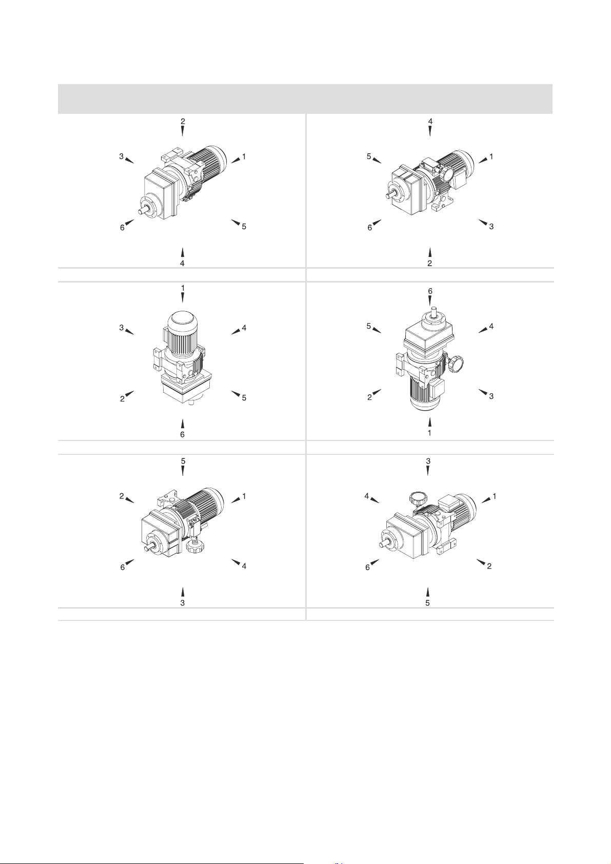
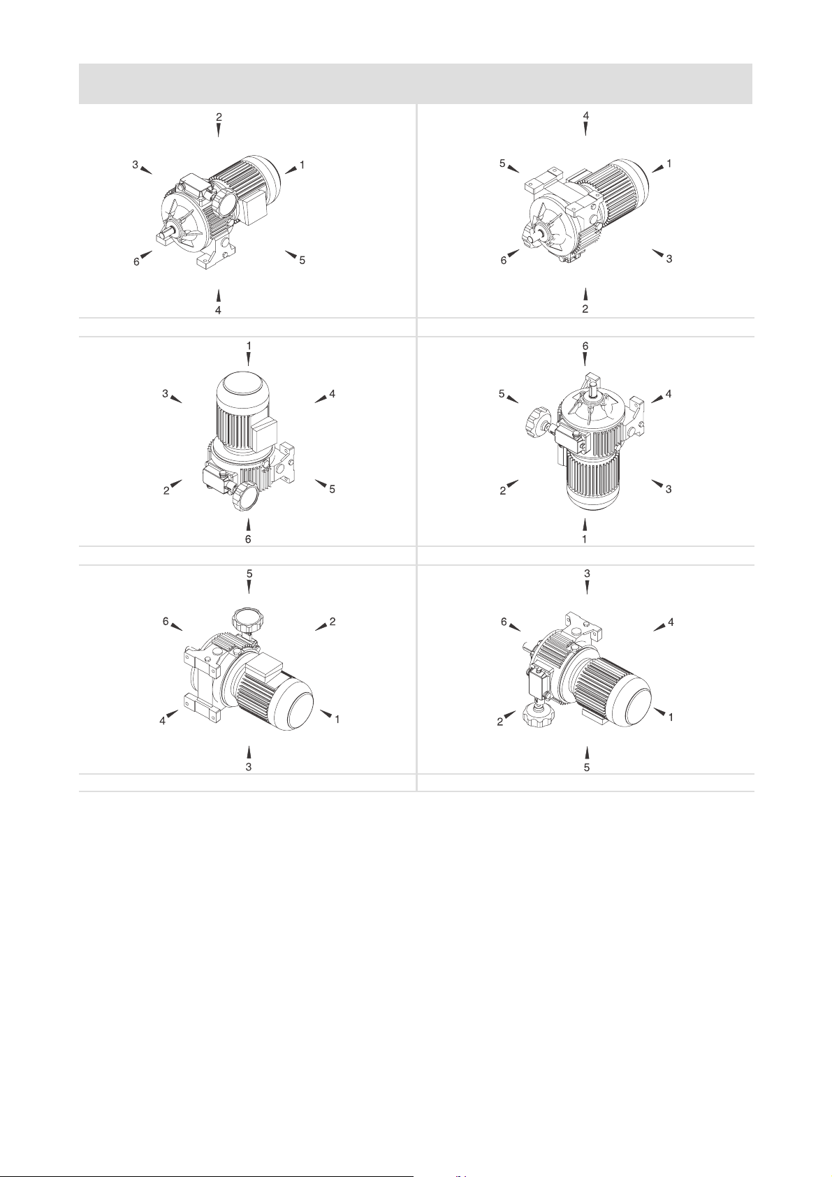
Mounting position (A−F) and position of system modules (1−6)
DISCO variable speed drive with helical gearbox
GST − 1D VDR (foot on variable speed drive)
Terminal box: 2, 3, 4, 5Spindle housing: 2, 3, 4, 5 Handwheel/adjusting device: 2, 3, 4, 5
A B
C D
E F
6
l
BA 11.5032−EN 3.0
Page 7

GST − D
Terminal box: 2, 3, 4, 5Spindle housing: 2, 3, 4, 5 Handwheel/adjusting device: 2, 3, 4, 5
A B
C D
E F
BA 11.5032−EN 3.0
l
7
Page 8
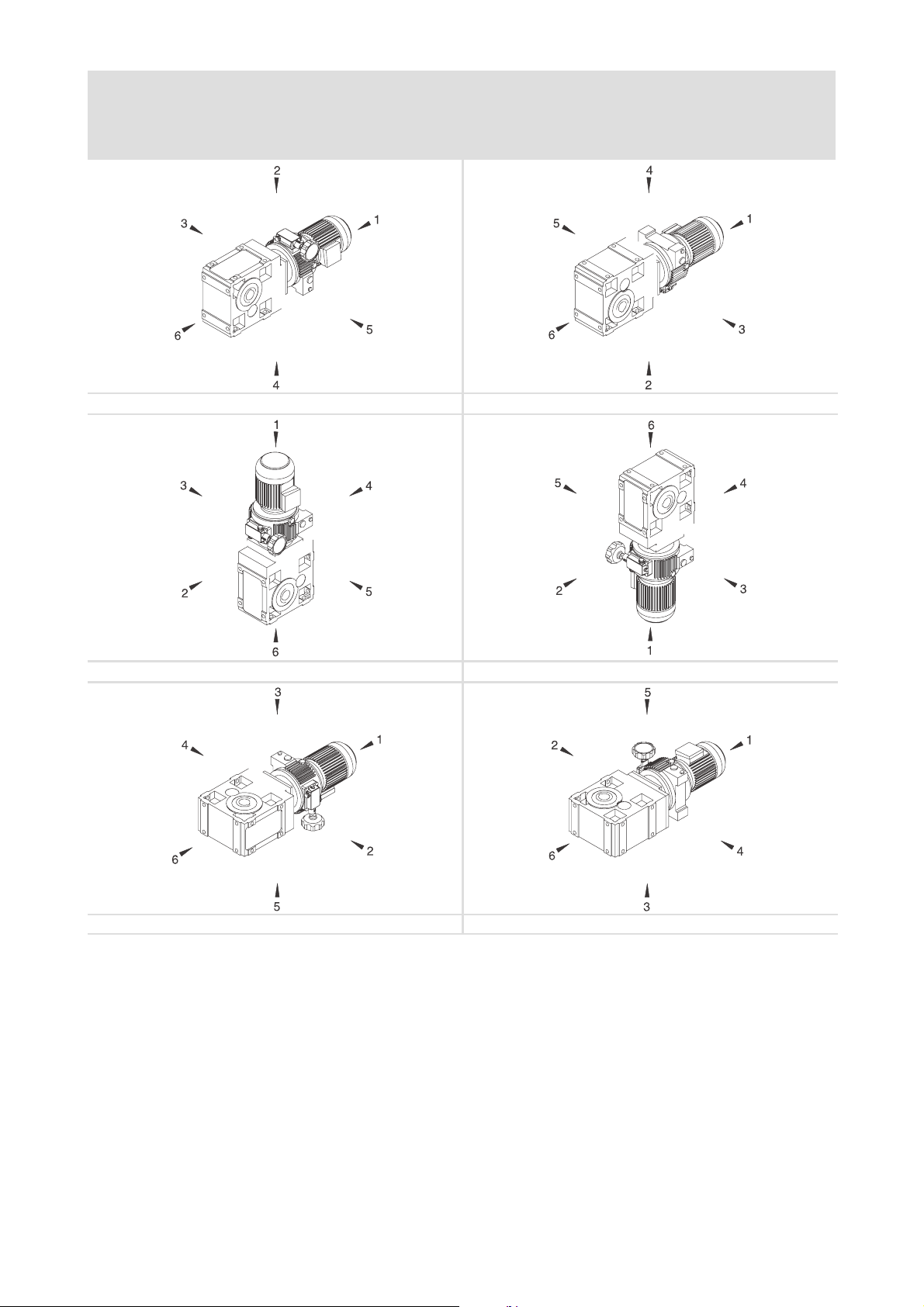
DISCO variable speed drive with helical−bevel gearbox and helical−worm gearbox
GKS − D / GSS − D
Solid shaft: 2, 3, 8 (3+5) Hollow shaft: 0 Hollow shaft with shrink disc: 3, 5
Flange: 2, 3, 8 (3+5) Without flange: 0
Terminal box: 2, 3, 4, 5 Spindle housing: 2, 3, 4, 5 Handwheel/adjusting device: 2, 3, 4, 5
A B
C D
E F
8
l
BA 11.5032−EN 3.0
Page 9
DISCO variable speed drive without rear−mounted gearbox
11.70
Terminal box: 2, 3, 4, 5Handwheel/adjusting device: 2, 3, 4, 5
A B
C D
E F
BA 11.5032−EN 3.0
l
9
Page 10

Contentsi
1 Preface and general information 12 . . . . . . . . . . . . . . . . . . . . . . . . . . . . . . . . . . . . . . . . . . . .
1.1 About these Operating Instructions 12 . . . . . . . . . . . . . . . . . . . . . . . . . . . . . . . . . . . . .
1.2 Terminology used 12 . . . . . . . . . . . . . . . . . . . . . . . . . . . . . . . . . . . . . . . . . . . . . . . . . . . .
1.3 Scope of supply 12 . . . . . . . . . . . . . . . . . . . . . . . . . . . . . . . . . . . . . . . . . . . . . . . . . . . . . .
1.4 Lenze drive systems 13 . . . . . . . . . . . . . . . . . . . . . . . . . . . . . . . . . . . . . . . . . . . . . . . . . . .
1.4.1 Labelling 13 . . . . . . . . . . . . . . . . . . . . . . . . . . . . . . . . . . . . . . . . . . . . . . . . . . . .
1.5 Legal regulations 13 . . . . . . . . . . . . . . . . . . . . . . . . . . . . . . . . . . . . . . . . . . . . . . . . . . . . .
2 Safety instructions 14 . . . . . . . . . . . . . . . . . . . . . . . . . . . . . . . . . . . . . . . . . . . . . . . . . . . . . . . . .
2.1 Personnel responsible for safety 14 . . . . . . . . . . . . . . . . . . . . . . . . . . . . . . . . . . . . . . . .
2.2 General safety information 14 . . . . . . . . . . . . . . . . . . . . . . . . . . . . . . . . . . . . . . . . . . . .
2.3 Definition of notes used 15 . . . . . . . . . . . . . . . . . . . . . . . . . . . . . . . . . . . . . . . . . . . . . . .
3 Technical data 16 . . . . . . . . . . . . . . . . . . . . . . . . . . . . . . . . . . . . . . . . . . . . . . . . . . . . . . . . . . . .
3.1 Product features 16 . . . . . . . . . . . . . . . . . . . . . . . . . . . . . . . . . . . . . . . . . . . . . . . . . . . . .
3.2 Transport weights 18 . . . . . . . . . . . . . . . . . . . . . . . . . . . . . . . . . . . . . . . . . . . . . . . . . . . .
3.3 Operating conditions 19 . . . . . . . . . . . . . . . . . . . . . . . . . . . . . . . . . . . . . . . . . . . . . . . . .
3.3.1 Temperatures 19 . . . . . . . . . . . . . . . . . . . . . . . . . . . . . . . . . . . . . . . . . . . . . . . .
3.3.2 Ambient conditions 19 . . . . . . . . . . . . . . . . . . . . . . . . . . . . . . . . . . . . . . . . . . .
4 Mechanical installation 20 . . . . . . . . . . . . . . . . . . . . . . . . . . . . . . . . . . . . . . . . . . . . . . . . . . . . .
4.1 Storage 20 . . . . . . . . . . . . . . . . . . . . . . . . . . . . . . . . . . . . . . . . . . . . . . . . . . . . . . . . . . . . .
4.2 Installation 20 . . . . . . . . . . . . . . . . . . . . . . . . . . . . . . . . . . . . . . . . . . . . . . . . . . . . . . . . . .
5 Electrical installation 21 . . . . . . . . . . . . . . . . . . . . . . . . . . . . . . . . . . . . . . . . . . . . . . . . . . . . . . .
5.1 Connection of main motor 21 . . . . . . . . . . . . . . . . . . . . . . . . . . . . . . . . . . . . . . . . . . . . .
5.2 Electrical adjusting device 21 . . . . . . . . . . . . . . . . . . . . . . . . . . . . . . . . . . . . . . . . . . . . .
5.2.1 Operational check 21 . . . . . . . . . . . . . . . . . . . . . . . . . . . . . . . . . . . . . . . . . . . .
6 Commissioning and operation 23 . . . . . . . . . . . . . . . . . . . . . . . . . . . . . . . . . . . . . . . . . . . . . . .
6.1 Before switching on 23 . . . . . . . . . . . . . . . . . . . . . . . . . . . . . . . . . . . . . . . . . . . . . . . . . .
6.2 During operation 23 . . . . . . . . . . . . . . . . . . . . . . . . . . . . . . . . . . . . . . . . . . . . . . . . . . . . .
7 Maintenance 24 . . . . . . . . . . . . . . . . . . . . . . . . . . . . . . . . . . . . . . . . . . . . . . . . . . . . . . . . . . . . .
7.1 Oil filling quantities for DISCO gearboxes 24 . . . . . . . . . . . . . . . . . . . . . . . . . . . . . . . .
7.1.1 Oil grades for DISCO variable speed drives 25 . . . . . . . . . . . . . . . . . . . . . . . .
7.1.2 Breather position, oil filling screw and drain plug 26 . . . . . . . . . . . . . . . . . .
7.2 Maintenance intervals 27 . . . . . . . . . . . . . . . . . . . . . . . . . . . . . . . . . . . . . . . . . . . . . . . .
7.3 Maintenance operations 27 . . . . . . . . . . . . . . . . . . . . . . . . . . . . . . . . . . . . . . . . . . . . . . .
7.3.1 Replacing the lubricant 27 . . . . . . . . . . . . . . . . . . . . . . . . . . . . . . . . . . . . . . . .
7.3.2 Spare parts list 27 . . . . . . . . . . . . . . . . . . . . . . . . . . . . . . . . . . . . . . . . . . . . . . .
7.4 Repair 27 . . . . . . . . . . . . . . . . . . . . . . . . . . . . . . . . . . . . . . . . . . . . . . . . . . . . . . . . . . . . . .
l 10
BA 11.5032−EN 3.0
Page 11

Contents i
8 Troubleshooting and fault elimination 28 . . . . . . . . . . . . . . . . . . . . . . . . . . . . . . . . . . . . . . .
9 Disposal 29 . . . . . . . . . . . . . . . . . . . . . . . . . . . . . . . . . . . . . . . . . . . . . . . . . . . . . . . . . . . . . . . . . .
10 Appendix 30 . . . . . . . . . . . . . . . . . . . . . . . . . . . . . . . . . . . . . . . . . . . . . . . . . . . . . . . . . . . . . . . .
10.1 Spare−parts list 30 . . . . . . . . . . . . . . . . . . . . . . . . . . . . . . . . . . . . . . . . . . . . . . . . . . . . . .
10.1.1 DISCO variable speed drive size 02 30 . . . . . . . . . . . . . . . . . . . . . . . . . . . . . .
10.1.2 DISCO variable speed drive size 03 32 . . . . . . . . . . . . . . . . . . . . . . . . . . . . . .
10.1.3 DISCO variable speed drive size 04−07 34 . . . . . . . . . . . . . . . . . . . . . . . . . . .
10.1.4 DISCO variable speed drive size 08−18 36 . . . . . . . . . . . . . . . . . . . . . . . . . . .
10.1.5 Speed adjustment mechanism, size 02−07 38 . . . . . . . . . . . . . . . . . . . . . . . .
10.1.6 Speed adjustment mechanisms, size 08−18 40 . . . . . . . . . . . . . . . . . . . . . . .
BA 11.5032−EN 3.0
l 11
Page 12

1
Preface and general information
About these Operating Instructions
1 Preface and general information
1.1 About these Operating Instructions
ƒ These Operating Instructions provide information about safety−relevant work on
and with DISCO variable speed drives. They contain safety instructions which must
be observed.
ƒ All personnel working on and with DISCO variable speed drives must have these
Operating Instructions available and observe the information and notes relevant for
them.
ƒ The Operating Instructions must always be in a complete and perfectly readable
state.
1.2 Terminology used
Term In the following text used for
DISCO Disco variable speed drive
Drive system Drive systems with DISCO variable speed drives and other drive
1.3 Scope of supply
ƒ The drive systems are combined individually according to a modular design. The
scope of supply can be obtained from the pertinent papers.
ƒ After receipt of the supply, check immediately whether it corresponds with the
accompanying papers. Lenze does not grant any warranty for subsequent claims.
Claim for
– visible transport damages immediately to the forwarder.
– visible deficiencies / incompleteness immediately to the responsible Lenze
subsidiary / agency.
components
12
l
BA 11.5032−EN 3.0
Page 13

1.4 Lenze drive systems
1.4.1 Labelling
Lenze drive systems are uniquely designated by the content of their nameplates.
Manufacturer
Lenze Drives GmbH
Postfach 10 13 52
D−31763 Hameln
Application as directed
ƒ Lenze drive systems
– are intended for use in machinery and plant,
– must only be used for the purposes ordered and confirmed,
– must only be operated under the ambient conditions prescribed in these
Operating Instructions,
– must not be operated beyond their corresponding power limits.
Preface and general information
Lenze drive systems
Labelling
1
Any other use shall be deemed inappropriate!
1.5 Legal regulations
Liability
ƒ The information, data, and notes in the Operating Instructions were state of the art
at the time of printing. Claims referring to drive systems which have already been
supplied cannot be derived from the information, illustrations, and descriptions.
ƒ We do not accept any liability for damage and operating interference caused by:
– inappropriate use,
– unauthorised modifications to the drive system,
– improper working on and with the drive system,
– operating faults,
– disregarding the Operating Instructions.
Warranty
ƒ Conditions of warranty: see terms of sale and delivery of Lenze Drive Systems
GmbH.
BA 11.5032−EN 3.0
ƒ Warranty claims must be made to Lenze immediately after detecting the deficiency
or fault.
ƒ The warranty is void where liability claims cannot be made.
l
13
Page 14

2
Safety instructions
Personnel responsible for safety
2 Safety instructions
2.1 Personnel responsible for safety
Operator
ƒ An operator is any natural or legal person who uses the drive system or on behalf of
whom the drive system is used.
ƒ The operator or his safety officer must ensure
– that all relevant regulations, instructions and legislation are observed.
– that only qualified personnel work with and on the drive system.
– that the personnel have the Operating Instructions available for all corresponding
operations.
– that non−qualified personnel are prohibited from working with and on the drive
system.
Skilled personnel
Skilled personnel are persons who − because of their education, experience, instructions,
and knowledge about corresponding standards and regulations, rules for the prevention
of accidents, and operating conditions − are authorised by the person responsible for the
safety of the plant to perform the required actions and who are able to recognise potential
hazards.
(See IEC 364, definition of skilled personnel)
2.2 General safety information
ƒ This safety information does not claimed to be complete. In case of questions and
problems, please contact your Lenze representative.
ƒ At the time of delivery the drive system meets the state of the art and ensures safe
basic operation.
ƒ The drive system is a source of danger for persons, for the drive system itself, and for
other material assets of the operator, if
– unqualified personnel works with and on the drive system,
– the drive system is used inappropriately.
14
ƒ The drive systems must be designed such that they perform their functions after
proper installation and with application as directed in fault−free operation and that
they do not cause hazards for persons. This also applies for their interaction with the
complete plant.
ƒ Be sure to take appropriate measures in the case of drive system failure so that no
material damage occurs.
ƒ Operate the drive system only when it is in a proper state.
ƒ Retrofittings, modifications, or redesigns of the drive system are basically
prohibited. Lenze must be contacted in all cases.
l
BA 11.5032−EN 3.0
Page 15

Safety instructions
Definition of notes used
2
2.3 Definition of notes used
The following pictographs and signal words are used in this documentation to indicate
dangers and important information:
Safety instructions
Structure of safety instructions:
} Danger!
(characterises the type and severity of danger)
Note
(describes the danger and gives information about how to prevent dangerous
situations)
Pictograph and signal word Meaning
{ Danger!
} Danger!
( Stop!
Danger of personal injury through dangerous electrical voltage.
Reference to an imminent danger that may result in death or
serious personal injury if the corresponding measures are not
taken.
Danger of personal injury through a general source of danger.
Reference to an imminent danger that may result in death or
serious personal injury if the corresponding measures are not
taken.
Danger of property damage.
Reference to a possible danger that may result in property damage
if the corresponding measures are not taken.
Application notes
Pictograph and signal word Meaning
) Note!
I Tip!
,
Important note to ensure troublefree operation
Useful tip for simple handling
Reference to another documentation
BA 11.5032−EN 3.0
l
15
Page 16

3
Technical data
Product features
3 Technical data
ƒ The most important technical data are provided on the nameplate (layout and
contents ^ page 4).
ƒ The product catalogues contain further technical data.
3.1 Product features
GT−DISCO−005.iso
Fig. 1 Layout of the DISCO variable speed drive
1 Pinion shaft 8 Clutch thrust collar
2 Left inner sun 9 Clutch collar
3 Right inner sun 10 Ball retainer ring
4 Disk spring 11 Pinion cage
5 Planet 13 Spindle
6 Slide block 14 Guide part
7 Thrust collar 15 Ball headed pin
The DISCO variable speed drive is a planetary gearbox, where all the functional parts run
in an oil bath. The planets, located in the pinion cage, rotate around the driving inner
sun. The speed and the force flow are transmitted from the drive shaft to the inner sun.
The flat, double−coned planets are driven by the inner sun, simultaneously rolling along
the outer rings which are fixed in the housing. So the planets don’t only rotate about
their own axes but also about the inner sun. They thus move the pinion cage with them,
which has a fixed connection with the output shaft.
The speed setting is altered by means of an adjustment spindle through rotating one of the
three outer rings on the housing. This moves the planets to a different radius of rotation,
depending on the size of the air gap between the outer rings. In this way, steplessly
adjustable output speeds are achieved. Supplementary gearboxes, in the form of single or
16
l
BA 11.5032−EN 3.0
Page 17

Technical data
Product features
multi−stage helical, conical or worm gearboxes, can be used to adjust output speed to the
requirements of the application.
( Stop!
The DISCO must only be changed to a fasterspeed while it is running!
Otherwise, the DISCO could be damaged!
Changing to a slowerspeed is allowed while the DISCO is standing still.
3
BA 11.5032−EN 3.0
l
17
Page 18

3
Technical data
Transport weights
3.2 Transport weights
DISCO with GST helical gearbox
Gearbox size
071−1 02 071−3 03 080−3 04 090−3 05 100−32 06 112−22 07 132−12 18 132−22 08
GST 04 < 18
GST 05 < 25 < 32 < 43
GST 06 < 36 < 40 < 51 < 67
GST 07 < 56 < 64 < 75 < 83 < 120 < 130
GST 09 < 99 < 110 < 127 < 150 < 161 < 223 < 230
GST 11 < 168 < 185 < 221 < 232 < 272 < 279
GST 14 < 296 < 333 < 343 < 406 < 413
Drive size
DISCO with GKS helical−bevel gearbox
Gearbox size
071−1 02 071−3 03 080−3 04 090−3 05 100−32 06 112−22 07 132−12 18 132−22 08
GKS 04 < 28
GKS 05 < 41 < 49 < 59
GKS 06 < 64 < 69 < 79 < 96
GKS 07 < 104 < 113 < 123 < 131 < 168 < 178
GKS 09 < 191 < 202 < 218 < 242 < 252 < 315 < 322
GKS 11 < 329 < 346 < 382 < 392 < 433 < 440
GKS 14 < 574 < 607 < 621 < 684 < 709
Drive size
DISCO with GSS helical−worm gearbox
Gearbox size
071−1 02 071−3 03 080−3 04 090−3 05 100−32 06 112−22 07
GSS 04 < 28
GSS 05 < 41 < 48 < 59
GSS 06 < 62 < 56 < 77 < 94
GSS 07 < 101 < 109 < 120 < 128 < 165 < 175
Drive size
DISCO type 11.700 / 11.710
DISCO
size
02 < 10 < 5
03 < 19 < 13
04 < 27 < 28 < 21
05 < 42 < 45 < 35
06 < 74 < 78 < 58
07 < 89 < 58
09 < 151 < 88
11 < 158 < 85
071−1 071−3 080−1 080−3 090−1 090−3 100−1 100−3 112−22 132−12 132−22
Weight in [kg] with oil filling, for mounting position A, all values are aproximate
Type 11.700 with motor size
Type
11.700
18
l
BA 11.5032−EN 3.0
Page 19

3.3 Operating conditions
3.3.1 Temperatures
ƒ DISCO: permissible ambient temperature −15 bis +40°C
ƒ Rear−mounted gearbox (see Operating Instructions for the gearbox)
ƒ Motor (see temperature class for the motor)
The operating temperature is determined by the power loss, the ambient temperature and
the cooling system!
3.3.2 Ambient conditions
ƒ DISCO variable speed drives are dust and hose−proof.
ƒ Motors corresponding to their degree of protection (s. nameplate and/or operating
instructions of the motor).
Technical data
Operating conditions
Temperatures
3
ƒ Ambient media − especially chemically aggressive − can damage shaft sealing rings
and lacquers (plastics in general). Abrasive media may damage the shaft sealing
rings.
BA 11.5032−EN 3.0
l
19
Page 20

4
Mechanical installation
Storage
4 Mechanical installation
} Danger!
Only transport the drive with transport equipment or hoists which are suitable
for this load (see transport weights, chapter 3.2). Ensure a safe fixing. Avoid
shocks!
The motors attached to the gearbox are partially equipped with eyebolts.
These are exclusively determined for motor/gearbox mounting and
dismounting and must not be used for the complete geared motor!
4.1 Storage
If you do not install the DISCO at once, please ensure proper storage conditions.
ƒ Up to one year:
– Without special measures in dry, dust−free enclosed rooms without direct sunlight.
– Store DISCO with ventilation in a manner that the breather screw is at the top.
– Shafts and bright surfaces are delivered with protection against corrosion.
ƒ Over one year:
– Please consult the factory.
4.2 Installation
Mount the drive systems on an even surface, free from distortion. If they are mounted on
a baseplate, then the baseplate must also be mounted without distortion. If this is not
done, then stresses appear in the gearbox housing and have a bad effect on the parallel
alignment of the shafts and thus on the bearing and tooth alignment.
The output shaft of the drive system must be well aligned with the machine shaft that is
to be driven. Small inaccuracies can be compensated by using a flexible coupling.
Couplings, gear wheels, sprockets etc. must only be fixed by screwing to the shaft ends of
the drive system. Driving them on can damage the ball bearings.
20
l
BA 11.5032−EN 3.0
Page 21

5 Electrical installation
{ Danger!
Electrical connections must only be carried out by skilled personnel!
{ Danger!
Always earth the drive!
If it is not possible to earth it via attached items (e.g. the motor) then the
gearbox must be earthed!
5.1 Connection of main motor
Electrical installation
Electrical adjusting device
5
To connect the motor correctly, you must follow:
ƒ the notes in the terminal box of the motor
ƒ the notes in the operating instructions of the motor
ƒ the technical data on the motor nameplate.
5.2 Electrical adjusting device
( Stop!
The DISCO must only be changed to a fasterspeed while it is running!
Otherwise, the DISCO could be damaged!
Changing to a slowerspeed is allowed while the DISCO is standing still.
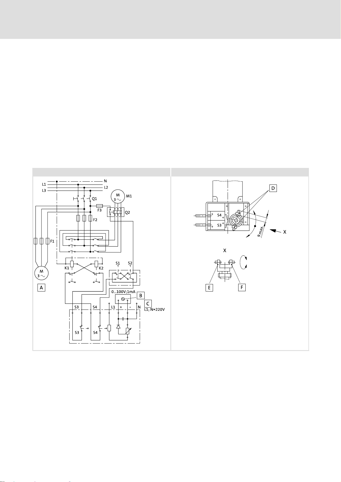
1. Connect the electrical adjustment device as shown in the circuit diagram (Fig. 2).
Ensure the right polarity of the adjustment motor!
2. It is vital to carry out a functional check in order to avoid damages to the DISCO.
– Check the positions of the adjustment motor and the limit−switch box, see page 6
Position of system blocks".
5.2.1 Operational check
Adjustment motor in position 5 / limit−switch box in position 3
1. Switch on the DISCO.
2. Increase the speed: counter−clockwise rotation of the actuator in the limit−switch
housing.
3. While the speed is increased activate the limit−switch S4 with an insulated
screwdriver.
BA 11.5032−EN 3.0
l
21
Page 22
5
Electrical installation
Electrical adjusting device
Operational check
4. The adjustment motor and actuator must stop.
5. If the actuator and adjustment motor do not stop, reverse the polarity of the
adjustment motor.
Adjustment motor in position 3 / limit−switch box in position 5
1. Switch on the DISCO.
2. Increase the speed: clockwise rotation of the actuator in the limit−switch housing.
3. While the speed is increased, activate the limit−switch S3 with an insulated
screwdriver.
4. The adjustment motor and actuator must stop.
5. If the actuator and adjustment motor do not stop, reverse the polarity of the
adjustment motor.
Adjustment motor in position 5 / limit−switch in position 3 Adjustment motor in position 3 / limit−switch in position 5
22
GT−DISCO−003.iso GT−DISCO−004.iso
Fig. 2 Circuit plan of the servo adjustment mechanism with potentiometer indicator
0 Driving motor 3 Actuator (the long lever activates S3)
1 Adjustable 4 Long lever
2 Auxiliary supply L1, N=230 V~ 5 Short lever
A1 Indicator 0...100V =/ 1000 W/V
(option)
F1, F2, F3 Fuses* Q2 Motor protection switch*
K1, K2 Reversing contactors* S1, S2 Pushbutton switches*
M1 Adjustment motor S3, S4 Limit switches
* not included in the scope of supply
Q1 Main switch*
l
BA 11.5032−EN 3.0
Page 23

Commissioning and operation
6 Commissioning and operation
( Stop!
Commissioning of the drive only by qualified staff!
6.1 Before switching on
Check:
ƒ Is the mechanical fixing o.k.?
ƒ Are the electrical connections o.k.?
ƒ Are all rotating parts and surfaces that may become hot protected against contact?
ƒ For gearboxes with breathing:
– Is the plug removed from the breather screw?
6
Before switching on
) Note!
Rear−mounted gearboxes must have separate ventilation, ^ Operating
Instruction of the gearbox!
6.2 During operation
( Stop!
During running−in, raised temperatures may occur over a period of 2 − 8 hours.
ƒ During operation, check the drive periodically and take special care of:
– unusual noises or temperatures,
– leakages,
– loose fixing elements,
– the condition of the electrical cables.
ƒ If any interference should occur, proceed according to the troubleshooting list in
chapter 8. If the interference cannot be eliminated, please contact the Lenze Service.
BA 11.5032−EN 3.0
l
23
Page 24
7
Maintenance
Oil filling quantities for DISCO gearboxes
7 Maintenance
The DISCO drives are supplied with oil filling.
) Note!
ƒ Lubricating instructions for rear−mounted gearboxes, see Operating
Instructions of the gearbox.
ƒ We recommend to check the oil level regularly!
ƒ If you use an oil not listed in Tab. 2, we recommend lubricants with the
following technical values:
– Viscosity: 32mm
– Flash point: ~ 210°C
– Pourpoint: ~ −30°C
– FZG test A8.3/90: damage force stage ³10
– Air release property: 5min. at 50°C
– Foam volume after air inlet at 25/95/25°C: 230/10/290 ml
2
/s ±10% at 40°C
7.1 Oil filling quantities for DISCO gearboxes
DISCO size
horizontal vertical
Spindle housing Output shaft
above side below below above
size 02
02 0,4 0,3 0,4 0,4 0,4
03 0,4 0,5 0,8 0,6 0,6
04 0,5 0,5 1,0 1,0 1,0
05 0,7 1,0 2,0 2,0 1,5
06/07 1,5 2,0 3,0 3,5 2,5
08 2,5 4,0 3,5 6,0 5,0
09 3,0 6,0 4,5 9,5 7,0
10/11 6,0 10,0 4,5 14,0 11,0
Tab. 1 Oil quantities − guide values
Mounting positions
size 02
size 03
sizes 03/04 K
sizes
02/03
GT−DISCO−008.iso
24
Oil sight glass Oil drain plug
K
Oil control plug Ventilation
Oil filler plug
l
BA 11.5032−EN 3.0
Page 25
Oil filling quantities for DISCO gearboxes
Oil grades for DISCO variable speed drives
7.1.1 Oil grades for DISCO variable speed drives
Maintenance
7
Manufacturer
Shell
Oil types
DISCO lifetime oil
Shell Tegula V 32
Astron HLP 32 / Pentran 32
LAMORA HLP 32
RENOLIN MR 10 VG 32 / RENOFLUID TF 1500
Degol GB 32
OSO 32 / BLASIA 32
Energol HL−XP 32 / Energol HLP−HM 32
Hyspin AWS 32 / Hyspin SP 32
TORQUE FLUID N 45
Wiolan HF 32
Rando Oil HD A−32
Tab. 2 Recommended oil grades for DISCO variable speed drives
BA 11.5032−EN 3.0
l
25
Page 26

7
Maintenance
Oil filling quantities for DISCO gearboxes
Breather position, oil filling screw and drain plug
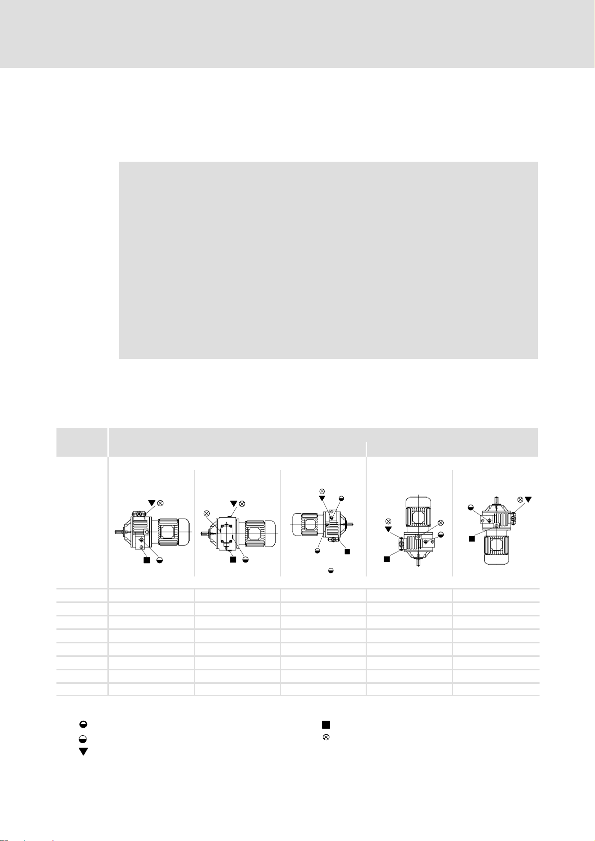
7.1.2 Breather position, oil filling screw and drain plug
GT−DISCO−007.cdr
Oil filling for gearboxes without ventilation Ventilation / oil filler plug
Oil drain plug Oil control plug
1) Facing the housing
2) In case of a position of the handle different from the shown one, the positions are facing the housing respectively
26
l
BA 11.5032−EN 3.0
Page 27

7.2 Maintenance intervals
ƒ The mechanical power transmission system is maintenance−free.
ƒ No oil change when DISCO lifetime oil is used.
If other oils are used, an oil change is necessary after every 2000 hours of operation.
ƒ Shaft seal rings:
– The operating life depends on the conditions of use.
– Replace leaking shaft seals to prevent further damage.
( Stop!
For drive systems: Also observe the maintenance intervals for the other drive
components!
7.3 Maintenance operations
Maintenance
Maintenance intervals
7
7.3.1 Replacing the lubricant
ƒ DISCO should be warm.
ƒ Secure the drive system and machinery against unintended movement or mains
power−up.
( Stop!
Rear−mounted gearboxes have separate lubrication; see the Operating
Instructions for gearboxes!
1. Drain lubricant through the outlet (^ Abb. in Tab. 1).
2. Insert oil drain plug with new seal.
3. Fill in lubricant through the inlet.
4. Fit the oil filler plug.
5. Dispose of the used oil according to current regulations.
7.3.2 Spare parts list
You find the spare parts list in the10appendix
7.4 Repair
Lenze recommends that repairs are carried out by the Lenze Service.
BA 11.5032−EN 3.0
l
27
Page 28

Troubleshooting and fault elimination8
8 Troubleshooting and fault elimination
Fault Possible cause Remedy
Drive does not start
Motor runs, gearbox does not
Unusual running noise
Excessive temperature
Loose fixing elements Vibrations Avoid vibrations
Voltage supply interrupted
Faulty electrical connection Check that supply voltage matches
Excessive load Reduce load
Coupling components are missing or
defective
Gearbox is defective Inform Lenze Service
Overload Reduce load
Damage to the gearbox or motor Inform Lenze Service
Overload Reduce load
Inadequate heat dissipation Improve cooling air flow
Lack of lubricant Top up lubricant according to regulations
Check connection
nameplate data
Check drive−machine assignment
Check mounting
Check drive−machine assignment
Check drive−machine assignment
Clean gearbox/motor
28
l
BA 11.5032−EN 3.0
Page 29

9 Disposal
Protect the environment! Valuable materials can be recycled.
What? Where?
Transport material Pallets Return to the manufacturer or
Lubricants Oil, grease Dispose according to current
Components Housing:
Disposal 9
forwarder
Packaging material Cardboard box to waste paper
Plastics to plastics recycling or
residual waste
Reuse or dispose of wood wool
regulations
Bearings, shafts, gear wheels:
Seals:
Cast iron
Steel
Hazardous waste
Separate different types of
material and dispose
BA 11.5032−EN 3.0
l
29
Page 30

10
Appendix
Spare−parts list
DISCO variable speed drive size 02
10 Appendix
10.1 Spare−parts list
10.1.1 DISCO variable speed drive size 02
4401
4420
4410
201
4421
220
221
1.07
1.03
4471
1.08
4424
4423
4425
30
l
BA 11.5032−EN 3.0
Page 31

Appendix 10
Pos. Name
0.25 Seal
0.26 Seal
0.28 Hexagon head cap screw
0.29
Locking washer for sizes 02−03
Spring washer for sizes 04−07
0.30 Cheese head screw
0.31 Spring washer
0.40 Oil sight glass
0.41 Locking screw
0.42 Angled breather tube
2.01 Cover
2.02 Shaft
2.04 Housing
2.05 Flange
2.06 Fan cover
2.07 Socket
2.08 Three−phase AC motor
2.09 Fan
2.10 Starting coupling
2.11 Flexible coupling
2.15 Deep−groove ball bearing
2.16 Deep−groove ball bearing
2.17 Inner ring
2.18 Shaft sealing ring
2.19 Circlip
2.20 Circlip
2.21 Circlip
2.22 Featherkey
2.23 Featherkey
2.24 Featherkey
2.25 Shim ring
2.27 Seal
2.28 Set screw
2.29 Set screw
2.30 Hexagon head cap screw
2.31
Locking washer for sizes 02−03
Spring washer for sizes 04−07
2.32 Cheese head screw
2.33 Seal
2.34 Cheese head screw
2.35 Spring washer
2.36 Hexagon head cap screw
2.37 Hexagon nut
2.38 Spring washer
3.01 Cover
3.03 Flange
3.05 Shaft
3.08 Hub
3.09 Pinion cage
3.10 Slide block
3.11 Socket
3.12 Washer
3.14 Clutch collar
3.15 Ball retainer ring
3.16 Clutch thrust collar
3.17 Flange
Pos. Name
3.19 Socket
3.26 Socket
3.27 Pressure spring
3.28 Deep−groove ball bearing
3.29 Deep−groove ball bearing
3.32 Deep−groove ball bearing
3.36 Shaft sealing ring
3.38 Circlip
3.39 Circlip
3.40 Circlip
3.41 Circlip
3.51 Circlip
3.52 Dowel pin
3.53 Hexagon head cap screw
3.56 Dowel pin
3.57 Dowel pin
3.58 Dowel pin
3.59 Cheese head screw
3.60 Spring washer
3.62 Cheese head screw
3.73 Set screw
3.76 Featherkey
3.78 Circlip
3.80 Seal
4.00 Spindle housing assembly
4.01 Spindle housing
4.02 Housing
4.03 Spindle
4.04 Guide part
4.05 Shaft
4.06 Ball headed pin
4.08 Socket
4.09 Adapter
4.10 Small worm−geared motor
4.12 Handwheel
4.13 Rotation−direction indicator
4.14 Setting indicator
4.15 Bevel
4.16 Bevel
4.17 Worm
4.20 Deep−groove ball bearing
4.21 Socket
4.22 Flange sleeve
4.23 Shaft sealing ring
4.24 Shaft sealing ring
4.25 Seal
4.26 Seal
4.27 Sealing ring
4.28 Circlip
4.29 Locking ring
4.31 Shim ring
4.32 Seeger ring
4.33 Dowel pin
4.34 Dowel pin
4.35 Dowel pin
4.36 Dowel pin
Pos. Name
4.37 Dowel pin
4.38 Dowel pin
4.39 Set screw
4.40 Set screw
4.41 Set screw
4.42 Conical plug
4.43 Protection cover
4.44
Hexagon head cap screw
Cheese head screw
4.45
Hexagon head cap screw
Cheese head screw
4.46 Spring washer
4.47 Cheese head screw
4.48 Circlip
4.51 Cover
4.52 Cheese head screw
4.53 Spring washer
4.55 Hub
4.56 Bell housing
4.57 Handle
4.58 Hexagon head cap screw
6.00 Inner sun assembly
6.01 Left inner sun
6.02 Right inner sun
6.03 Planet
6.04 Pressure disc
6.05 Disk spring
6.06 Circlip
201 Pinion
220 O−ring
221 Hexagon head cap screw
4401 Flange
4410 Shaft
4420 Deep−groove ball bearing
4421 Shaft sealing ring
4422 Circlip
4423 Deep−groove ball bearing
4424 Adapter disc
4425 Circlip
4471 Hexagon head cap screw
BA 11.5032−EN 3.0
l
31
Page 32

10
Appendix
DISCO variable speed drive size 03
10.1.2 DISCO variable speed drive size 03
4401
4410
201
4420
4421
220
221
4471
1.08
4422
4423
4425
32
l
BA 11.5032−EN 3.0
Page 33

Appendix 10
Pos. Name
0.25 Seal
0.26 Seal
0.28 Hexagon head cap screw
0.29
Locking washer for sizes 02−03
Spring washer for sizes 04−07
0.30 Cheese head screw
0.31 Spring washer
0.40 Oil sight glass
0.41 Locking screw
0.42 Angled breather tube
1.01 Housing
1.02 Thrust collar
1.03 Foot
1.04 Set screw
1.05 Seal−Lock hexagon nut
1.06 Dowel pin
1.07 Cheese head screw
1.08 Oil sight glass
2.01 Cover
2.02 Shaft
2.04 Housing
2.05 Flange
2.06 Fan cover
2.07 Socket
2.08 Three−phase AC motor
2.09 Fan
2.10 Starting coupling
2.11 Flexible coupling
2.15 Deep−groove ball bearing
2.16 Deep−groove ball bearing
2.17 Inner ring
2.18 Shaft sealing ring
2.19 Circlip
2.20 Circlip
2.21 Circlip
2.22 Featherkey
2.23 Featherkey
2.24 Featherkey
2.25 Shim ring
2.27 Seal
2.28 Set screw
2.29 Set screw
2.30 Hexagon head cap screw
2.31
Locking washer for sizes 02−03
Spring washer for sizes 04−07
2.32 Cheese head screw
2.33 Seal
2.34 Cheese head screw
2.35 Spring washer
2.36 Hexagon head cap screw
2.37 Hexagon nut
2.38 Spring washer
3.01 Cover
3.03 Flange
3.05 Shaft
3.08 Hub
Pos. Name
3.09 Pinion cage
3.10 Slide block
3.11 Socket
3.12 Washer
3.14 Clutch collar
3.15 Ball retainer ring
3.16 Clutch thrust collar
3.17 Flange
3.19 Socket
3.26 Socket
3.27 Pressure spring
3.28 Deep−groove ball bearing
3.29 Deep−groove ball bearing
3.32 Deep−groove ball bearing
3.36 Shaft sealing ring
3.38 Circlip
3.39 Circlip
3.40 Circlip
3.41 Circlip
3.51 Circlip
3.52 Dowel pin
3.53 Hexagon head cap screw
3.56 Dowel pin
3.57 Dowel pin
3.58 Dowel pin
3.59 Cheese head screw
3.60 Spring washer
3.62 Cheese head screw
3.73 Set screw
3.76 Featherkey
3.78 Circlip
3.80 Seal
4.00 Spindle housing assembly
4.01 Spindle housing
4.02 Housing
4.03 Spindle
4.04 Guide part
4.05 Shaft
4.06 Ball headed pin
4.08 Socket
4.09 Adapter
4.10 Small worm−geared motor
4.12 Handwheel
4.13 Rotation−direction indicator
4.14 Setting indicator
4.15 Bevel
4.16 Bevel
4.17 Worm
4.20 Deep−groove ball bearing
4.21 Socket
4.22 Flange sleeve
4.23 Shaft sealing ring
4.24 Shaft sealing ring
4.25 Seal
4.26 Seal
4.27 Sealing ring
Pos. Name
4.28 Circlip
4.29 Locking ring
4.31 Shim ring
4.32 Seeger ring
4.33 Dowel pin
4.34 Dowel pin
4.35 Dowel pin
4.36 Dowel pin
4.37 Dowel pin
4.38 Dowel pin
4.39 Set screw
4.40 Set screw
4.41 Set screw
4.42 Conical plug
4.43 Protection cover
4.44
Hexagon head cap screw
Cheese head screw
4.45
Hexagon head cap screw
Cheese head screw
4.46 Spring washer
4.47 Cheese head screw
4.48 Circlip
4.51 Cover
4.52 Cheese head screw
4.53 Spring washer
4.55 Hub
4.56 Bell housing
4.57 Handle
4.58 Hexagon head cap screw
201 Pinion
220 O−ring
221 Hexagon head cap screw
4401 Flange
4410 Shaft
4420 Deep−groove ball bearing
4421 Shaft sealing ring
4422 Circlip
4423 Deep−groove ball bearing
4424 Adapter disc
4425 Circlip
4471 Hexagon head cap screw
BA 11.5032−EN 3.0
l
33
Page 34

10
10.1.3 DISCO variable speed drive size 04−07
Appendix
DISCO variable speed drive size 04−07
4401
4421
4410
201
4420
220
221
4471
1.08
4425 4423 4422
34
l
BA 11.5032−EN 3.0
Page 35

Appendix 10
Pos. Name
0.25 Seal
0.26 Seal
0.28 Hexagon head cap screw
0.29
Locking washer for sizes 02−03
Spring washer for sizes 04−07
0.30 Cheese head screw
0.31 Spring washer
0.40 Oil sight glass
0.41 Locking screw
0.42 Angled breather tube
1.01 Housing
1.02 Thrust collar
1.03 Foot
1.04 Set screw
1.05 Seal−Lock hexagon nut
1.06 Dowel pin
1.07 Cheese head screw
1.08 Oil sight glass
2.01 Cover
2.02 Shaft
2.04 Housing
2.05 Flange
2.06 Fan cover
2.07 Socket
2.08 Three−phase AC motor
2.09 Fan
2.10 Starting coupling
2.11 Flexible coupling
2.15 Deep−groove ball bearing
2.16 Deep−groove ball bearing
2.17 Inner ring
2.18 Shaft sealing ring
2.19 Circlip
2.20 Circlip
2.21 Circlip
2.22 Featherkey
2.23 Featherkey
2.24 Featherkey
2.25 Shim ring
2.27 Seal
2.28 Set screw
2.29 Set screw
2.30 Hexagon head cap screw
2.31
Locking washer for sizes 02−03
Spring washer for sizes 04−07
2.32 Cheese head screw
2.33 Seal
2.34 Cheese head screw
2.35 Spring washer
2.36 Hexagon head cap screw
2.37 Hexagon nut
2.38 Spring washer
3.01 Cover
3.03 Flange
3.05 Shaft
3.08 Hub
Pos. Name
3.09 Pinion cage
3.10 Slide block
3.11 Socket
3.12 Washer
3.14 Clutch collar
3.15 Ball retainer ring
3.16 Clutch thrust collar
3.17 Flange
3.19 Socket
3.26 Socket
3.27 Pressure spring
3.28 Deep−groove ball bearing
3.29 Deep−groove ball bearing
3.32 Deep−groove ball bearing
3.36 Shaft sealing ring
3.38 Circlip
3.39 Circlip
3.40 Circlip
3.41 Circlip
3.51 Circlip
3.52 Dowel pin
3.53 Hexagon head cap screw
3.56 Dowel pin
3.57 Dowel pin
3.58 Dowel pin
3.59 Cheese head screw
3.60 Spring washer
3.62 Cheese head screw
3.73 Set screw
3.76 Featherkey
3.78 Circlip
3.80 Seal
4.00 Spindle housing assembly
4.01 Spindle housing
4.02 Housing
4.03 Spindle
4.04 Guide part
4.05 Shaft
4.06 Ball headed pin
4.08 Socket
4.09 Adapter
4.10 Small worm−geared motor
4.12 Handwheel
4.13 Rotation−direction indicator
4.14 Setting indicator
4.15 Bevel
4.16 Bevel
4.17 Worm
4.20 Deep−groove ball bearing
4.21 Socket
4.22 Flange sleeve
4.23 Shaft sealing ring
4.24 Shaft sealing ring
4.25 Seal
4.26 Seal
4.27 Sealing ring
Pos. Name
4.28 Circlip
4.29 Locking ring
4.31 Shim ring
4.32 Seeger ring
4.33 Dowel pin
4.34 Dowel pin
4.35 Dowel pin
4.36 Dowel pin
4.37 Dowel pin
4.38 Dowel pin
4.39 Set screw
4.40 Set screw
4.41 Set screw
4.42 Conical plug
4.43 Protection cover
4.44
Hexagon head cap screw
Cheese head screw
4.45
Hexagon head cap screw
Cheese head screw
4.46 Spring washer
4.47 Cheese head screw
4.48 Circlip
4.51 Cover
4.52 Cheese head screw
4.53 Spring washer
4.55 Hub
4.56 Bell housing
4.57 Handle
4.58 Hexagon head cap screw
6.00 Inner sun assembly
6.01 Left inner sun
6.02 Right inner sun
6.03 Planet
6.04 Pressure disc
6.05 Disk spring
6.06 Circlip
201 Pinion
220 O−ring
221 Hexagon head cap screw
4401 Flange
4410 Shaft
4420 Deep−groove ball bearing
4421 Shaft sealing ring
4422 Circlip
4423 Deep−groove ball bearing
4424 Adapter disc
4425 Circlip
4471 Hexagon head cap screw
BA 11.5032−EN 3.0
l
35
Page 36

10
Appendix
DISCO variable speed drive size 08−18
10.1.4 DISCO variable speed drive size 08−18
4401 4471
4421
4410
201
4420
220
221
4422 4423
4424
1.08
4425
36
l
BA 11.5032−EN 3.0
Page 37

Appendix 10
Pos. Name
0.25 Seal
0.26 Seal
0.28 Hexagon head cap screw
0.29
Locking washer for sizes 02−03
Spring washer for sizes 04−07
0.30 Cheese head screw
0.31 Spring washer
0.40 Oil sight glass
0.41 Locking screw
0.42 Angled breather tube
1.01 Housing
1.02 Thrust collar
1.03 Foot
1.04 Set screw
1.05 Seal−Lock hexagon nut
1.06 Dowel pin
1.07 Cheese head screw
1.08 Oil sight glass
2.01 Cover
2.02 Shaft
2.04 Housing
2.05 Flange
2.06 Fan cover
2.07 Socket
2.08 Three−phase AC motor
2.09 Fan
2.10 Starting coupling
2.11 Flexible coupling
2.15 Deep−groove ball bearing
2.16 Deep−groove ball bearing
2.17 Inner ring
2.18 Shaft sealing ring
2.19 Circlip
2.20 Circlip
2.21 Circlip
2.22 Featherkey
2.23 Featherkey
2.24 Featherkey
2.25 Shim ring
2.27 Seal
2.28 Set screw
2.29 Set screw
2.30 Hexagon head cap screw
2.31
Locking washer for sizes 02−03
Spring washer for sizes 04−07
2.32 Cheese head screw
2.33 Seal
2.34 Cheese head screw
2.35 Spring washer
2.36 Hexagon head cap screw
2.37 Hexagon nut
2.38 Spring washer
Pos. Name
3.01 Cover
3.03 Flange
3.05 Shaft
3.08 Hub
3.09 Pinion cage
3.10 Slide block
3.11 Socket
3.12 Washer
3.14 Clutch collar
3.15 Ball retainer ring
3.16 Clutch thrust collar
3.17 Flange
3.19 Socket
3.26 Socket
3.27 Pressure spring
3.28 Deep−groove ball bearing
3.29 Deep−groove ball bearing
3.32 Deep−groove ball bearing
3.36 Shaft sealing ring
3.38 Circlip
3.39 Circlip
3.40 Circlip
3.41 Circlip
3.51 Circlip
3.52 Dowel pin
3.53 Hexagon head cap screw
3.56 Dowel pin
3.57 Dowel pin
3.58 Dowel pin
3.59 Cheese head screw
3.60 Spring washer
3.62 Cheese head screw
3.73 Set screw
3.76 Featherkey
3.78 Circlip
3.80 Seal
6.00 Inner sun assembly
6.01 Left inner sun
6.02 Right inner sun
6.03 Planet
6.04 Pressure disc
6.05 Disk spring
6.06 Circlip
201 Pinion
220 O−ring
221 Hexagon head cap screw
Pos. Name
4401 Flange
4410 Shaft
4420 Deep−groove ball bearing
4421 Shaft sealing ring
4422 Circlip
4423 Deep−groove ball bearing
4424 Adapter disc
4425 Circlip
4471 Hexagon head cap screw
BA 11.5032−EN 3.0
l
37
Page 38

10
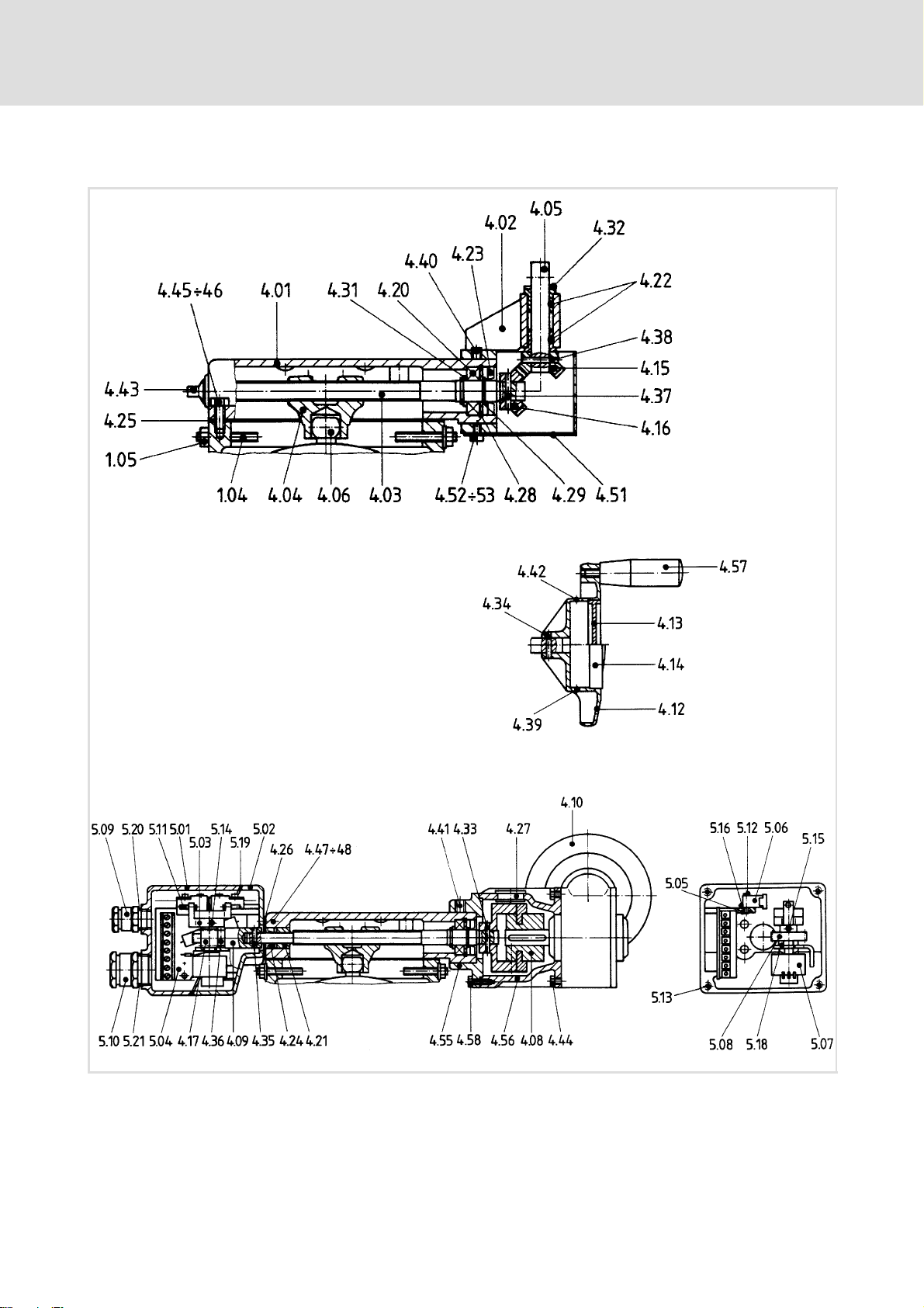
10.1.5 Speed adjustment mechanism, size 02−07
Appendix
Speed adjustment mechanism, size 02−07
38
l
BA 11.5032−EN 3.0
Page 39

Appendix 10
Pos. Name
4.00 Spindle housing assembly
4.01 Spindle housing
4.02 Housing
4.03 Spindle
4.04 Guide part
4.05 Shaft
4.06 Ball headed pin
4.08 Socket
4.09 Adapter
4.10 Small worm−geared motor
4.12 Handwheel
4.13 Rotation−direction indicator
4.14 Setting indicator
4.15 Bevel
4.16 Bevel
4.17 Worm
4.20 Deep−groove ball bearing
4.21 Socket
4.22 Flange sleeve
4.23 Shaft sealing ring
4.24 Shaft sealing ring
4.25 Seal
4.26 Seal
4.27 Sealing ring
4.28 Circlip
4.29 Locking ring
4.31 Shim ring
4.32 Seeger ring
4.33 Dowel pin
4.34 Dowel pin
4.35 Dowel pin
4.36 Dowel pin
4.37 Dowel pin
4.38 Dowel pin
4.39 Set screw
4.40 Set screw
4.41 Set screw
4.42 Conical plug
4.43 Protection cover
4.44
Hexagon head cap screw
Cheese head screw
4.45
Hexagon head cap screw
Cheese head screw
4.46 Spring washer
4.47 Cheese head screw
4.48 Circlip
4.51 Cover
4.52 Cheese head screw
4.53 Spring washer
4.55 Hub
4.56 Bell housing
4.57 Handle
4.58 Hexagon head cap screw
Pos. Name
5.00 Limit−switch assembly
5.01 Housing
5.02 Housing
5.03 Actuator
5.04 Board assembly
5.05 Plate
5.06 Microswitch
5.07 Potentiometer
5.08 Worm
5.09 Screw joint
5.10 Screw joint
5.11 Set screw
5.12 Cheese head screw
5.13 Screw
5.14 Set screw
5.15 Set screw
5.16 Adapter
5.18 Circlip
5.19 Seal
5.20 O−ring
5.21 O−ring
7.00 Spindle housing assembly
7.01 Spindle housing
7.03 Spindle
7.04 Guide part
7.23 O−ring
7.25 Seal
7.29 Keeper plate
7.31 Shim ring
7.75 Flange sleeve
BA 11.5032−EN 3.0
l
39
Page 40
10
10.1.6 Speed adjustment mechanisms, size 08−18
Appendix
Speed adjustment mechanisms, size 08−18
40
l
BA 11.5032−EN 3.0
Page 41

Appendix 10
Pos. Name
1.01 Housing
1.02 Thrust collar
1.03 Foot
1.04 Set screw
1.05 Seal−Lock hexagon nut
1.06 Dowel pin
1.07 Cheese head screw
1.08 Oil sight glass
4.00 Spindle housing assembly
4.01 Spindle housing
4.02 Housing
4.03 Spindle
4.04 Guide part
4.05 Shaft
4.06 Ball headed pin
4.08 Socket
4.09 Adapter
4.10 Small worm−geared motor
4.12 Handwheel
4.13 Rotation−direction indicator
4.14 Setting indicator
4.15 Bevel
4.16 Bevel
4.17 Worm
4.20 Deep−groove ball bearing
4.21 Socket
4.22 Flange sleeve
4.23 Shaft sealing ring
4.24 Shaft sealing ring
4.25 Seal
4.26 Seal
4.27 Sealing ring
4.28 Circlip
4.29 Locking ring
4.31 Shim ring
4.32 Seeger ring
4.33 Dowel pin
4.34 Dowel pin
4.35 Dowel pin
4.36 Dowel pin
4.37 Dowel pin
4.38 Dowel pin
4.39 Set screw
4.40 Set screw
4.41 Set screw
4.42 Conical plug
4.43 Protection cover
4.44
Hexagon head cap screw
Cheese head screw
4.45
Hexagon head cap screw
Cheese head screw
4.46 Spring washer
4.47 Cheese head screw
4.48 Circlip
4.51 Cover
4.52 Cheese head screw
Pos. Name
4.53 Spring washer
4.55 Hub
4.56 Bell housing
4.57 Handle
4.58 Hexagon head cap screw
5.00 Limit−switch assembly
5.01 Housing
5.02 Housing
5.03 Actuator
5.04 Board assembly
5.05 Plate
5.06 Microswitch
5.07 Potentiometer
5.08 Worm
5.09 Screw joint
5.10 Screw joint
5.11 Set screw
5.12 Cheese head screw
5.13 Screw
5.14 Set screw
5.15 Set screw
5.16 Adapter
5.18 Circlip
5.19 Seal
5.20 O−ring
5.21 O−ring
BA 11.5032−EN 3.0
l
41
Page 42

Notes!
42
l
BA 11.5032−EN 3.0
Page 43

Notes !
BA 11.5032−EN 3.0
l
43
Page 44

Q
Lenze Drives GmbH
Postfach 10 13 52
D−31763 Hameln
Germany
(
( Service
Ê Service
E−Mail Lenze@Lenze.de
Internet www.Lenze.com
+49(0)5154/ 82−0
008000/ 2446877 (24 h helpline)
+49(0)5154/ 82−28 00
BA 11.5032−EN 3.0 12/2008
© 2008
TD09
10987654321
 Loading...