

Page 1
MA_CSx0xx
.NGC
L−force Controls
Montageanleitung
Mounting Instructions
Instructions de montage
Ä.NGCä
Instrucciones para el montaje
Istruzioni per il montaggio
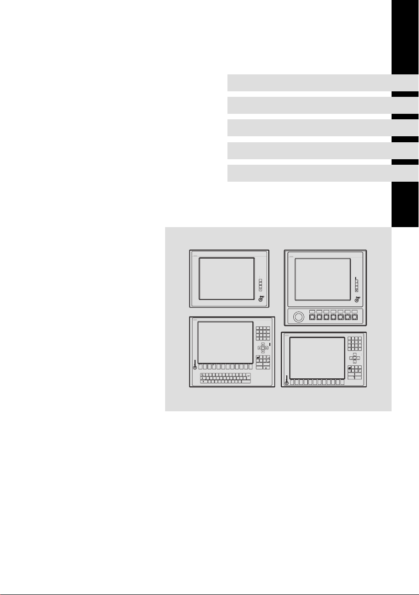
Industrial PC
Power
Fail
Status
F1
F2
+
F3
-
/
(
)
-
879
&
$
+
546
§
"
!
123
*
=
>
,
|
<
/
0
Power
Fail
Status
Bs
Entf
Bild
Einfg
Alt Gr
Bild
Pos 1
+
-
F4
F3F1 F2
F5
EWQ
T
R
OIPÜUZ
@
€
D
SA
GHJ
F
;
XY
NB
VC
M
,
μ
CS 5000 DVI ... CS 9000 DVI
Ende
Alt Strg
F9F8F6 F7 F10
F12
Esc
F11
*
~
+
Enter
Ä
LK
Ö
\?ß
_
:
Space
-
.
Q+R
ST
-
F1 F2 F5
F3 F4
Power
Fail
Status
F1
F2
+
F3
-
A
BCD
-
8
7
9
E
FGH
4
5
+6
I
JKL
3
1
2
*
M
NOP
,
.
0
/
Power
Pg Up
Fail
Status
Home
End
Pg Dn
EscDelIns
Bs
Menu
AltCtrl
Shift
Space
Alpha
Enter
@\Z
WVU
F11F10YXF9F8 F12
F7F6
Monitor Panel (Command Station)
Page 2

Lesen Sie zuerst diese Anleitung, bevor Sie mit den Arbeiten beginnen!
Beachten Sie die enthaltenen Sicherheitshinweise.
Ausführliche Informationen finden Sie in der Betriebsanleitung.
Read these instructions before you start working!
Follow the safety instructions given.
More detailed information can be found in the Operating Instructions.
Veuillez lire attentivement cette documentation avant toute action !
Les consignes de sécurité doivent impérativement être respectées.
Pour plus de détails, consulter les instructions de mise en service.
Lea estas instrucciones antes de empezar a trabajar.
Observe las instrucciones de seguridad indicadas.
El manual de instrucciones implica informaciónes detalladas.
Prima di iniziare qualsiasi intervento, leggere le presenti istruzioni.
Osservare le note di sicurezza.
Le istruzioni operative contengono informazioni dettagliati.
Page 3

Inhalt i
1 Über diese Dokumentation 4. . . . . . . . . . . . . . . . . . . . . . . . . . . . . . . . . . . . . . . . .
1.1 Verwendete Hinweise 4. . . . . . . . . . . . . . . . . . . . . . . . . . . . . . . . . . . . . . .
3 Sicherheitshinweise 5. . . . . . . . . . . . . . . . . . . . . . . . . . . . . . . . . . . . . . . . . . . . . . .
3.1 Allgemeine Sicherheitshinweise 5. . . . . . . . . . . . . . . . . . . . . . . . . . . . . .
3.2 Sicherheitshinweise für die Installation nach UL 6. . . . . . . . . . . . . . . . .
4 Produktbeschreibung 10. . . . . . . . . . . . . . . . . . . . . . . . . . . . . . . . . . . . . . . . . . . . .
4.1 Lieferumfang 10. . . . . . . . . . . . . . . . . . . . . . . . . . . . . . . . . . . . . . . . . . . . . .
4.2 Bedien− und Anzeigeelemente 10. . . . . . . . . . . . . . . . . . . . . . . . . . . . . . . .
5 Installation 11. . . . . . . . . . . . . . . . . . . . . . . . . . . . . . . . . . . . . . . . . . . . . . . . . . . . . .
5.1 Wichtige Hinweise 11. . . . . . . . . . . . . . . . . . . . . . . . . . . . . . . . . . . . . . . . . .
5.3 Montageschritte 12. . . . . . . . . . . . . . . . . . . . . . . . . . . . . . . . . . . . . . . . . . .
5.3.1 Montagewanne demontieren 12. . . . . . . . . . . . . . . . . . . . . . .
5.3.2 Montagewanne an Tragarm montieren 13. . . . . . . . . . . . . . .
5.3.3 Montagewanne an Wand montieren 15. . . . . . . . . . . . . . . . . .
5.4 Elektrische Installation 17. . . . . . . . . . . . . . . . . . . . . . . . . . . . . . . . . . . . . .
MA_CSx0xx DE/EN/FR/ES/IT 2.0
3
Page 4
1
Über diese Dokumentation
Verwendete Hinweise
1 Über diese Dokumentation
0Abb. 0Tab. 0
1.1 Verwendete Hinweise
Um auf Gefahren und wichtige Informationen hinzuweisen, werden in dieser
Dokumentation folgende Piktogramme und Signalwörter verwendet:
Sicherheitshinweise
Aufbau der Sicherheitshinweise:
Gefahr!
(kennzeichnet die Art und die Schwere der Gefahr)
Hinweistext
(beschreibt die Gefahr und gibt Hinweise, wie sie vermieden werden
kann)
Piktogramm und Signalwort Bedeutung
Gefahr!
Gefahr!
Stop!
Anwendungshinweise
Gefahr von Personenschäden durch gefährliche elektrische Spannung
Hinweis auf eine unmittelbar drohende Gefahr, die den
Tod oder schwere Verletzungen zur Folge haben kann,
wenn nicht die entsprechenden Maßnahmen getroffen
werden.
Gefahr von Personenschäden durch eine allgemeine
Gefahrenquelle
Hinweis auf eine unmittelbar drohende Gefahr, die den
Tod oder schwere Verletzungen zur Folge haben kann,
wenn nicht die entsprechenden Maßnahmen getroffen
werden.
Gefahr von Sachschäden
Hinweis auf eine mögliche Gefahr, die Sachschäden zur
Folge haben kann, wenn nicht die entsprechenden Maßnahmen getroffen werden.
Piktogramm und Signalwort Bedeutung
Hinweis!
Tipp!
4
Wichtiger Hinweis für die störungsfreie Funktion
Nützlicher Tipp für die einfache Handhabung
Verweis auf andere Dokumentation
MA_CSx0xx DE/EN/FR/ES/IT 2.0
Page 5

2 Sicherheitshinweise
2.1 Allgemeine Sicherheitshinweise
Auch zu Ihrer eigenen Sicherheit
Gefahr!
Wenn Sie die folgenden grundlegenden Sicherheitsmaßnahmen
missachten, kann dies zu schweren Personenschäden und
Sachschäden führen:
ƒ Lenze−Antriebs− und Automatisierungskomponenten ...
... ausschließlich bestimmungsgemäß verwenden.
... niemals trotz erkennbarer Schäden in Betrieb nehmen.
... niemals technisch verändern.
... niemals unvollständig montiert in Betrieb nehmen.
... niemals ohne erforderliche Abdeckungen betreiben.
... können während und nach dem Betrieb − ihrer Schutzart entsprechend −
spannungsführende, auch bewegliche oder rotierende Teile haben. Oberflächen können heiß sein.
ƒ Für Lenze−Antriebs− und Automatisierungskomponenten ...
... nur das zugelassene Zubehör verwenden.
... nur Original−Ersatzteile des Herstellers verwenden.
ƒ Alle Vorgaben der beiliegenden und zugehörigen Dokumentation
beachten.
Dies ist Voraussetzung für einen sicheren und störungsfreien Betrieb sowie
für das Erreichen der angegebenen Produkteigenschaften.
Die in diesem Dokument dargestellten verfahrenstechnischen Hinweise
und Schaltungsausschnitte sind Vorschläge, deren Übertragbarkeit auf die
jeweilige Anwendung überprüft werden muss. Für die Eignung der angegebenen Verfahren und Schaltungsvorschläge übernimmt der Hersteller keine
Gewähr.
ƒ Alle Arbeiten mit und an Lenze−Antriebs− und
Automatisierungskomponenten darf nur qualifiziertes Fachpersonal
ausführen.
Nach IEC 60364 bzw. CENELEC HD 384 sind dies Personen, ...
... die mit Aufstellung, Montage, Inbetriebsetzung und Betrieb des Produkts
vertraut sind.
... die über die entsprechenden Qualifikationen für ihre Tätigkeit verfügen.
... die alle am Einsatzort geltenden Unfallverhütungsvorschriften, Richtli-
nien und Gesetze kennen und anwenden können.
Sicherheitshinweise
Allgemeine Sicherheitshinweise
2
MA_CSx0xx DE/EN/FR/ES/IT 2.0
5
Page 6

2
2.2 Sicherheitshinweise für die Installation nach UL
Sicherheitshinweise
Sicherheitshinweise für die Installation nach UL
Original − Englisch
Approval
Underwriter Laboratories (UL), UL508 and CSA C22.2 No. 142−M1987, (UL File
Number E236341)
6
MA_CSx0xx DE/EN/FR/ES/IT 2.0
Page 7

Sicherheitshinweise
Sicherheitshinweise für die Installation nach UL
Ratings
ƒ Input 24 V DC, max. 65 W (65 VA)
ƒ Max. ambient temperature 40 °C
ƒ Environmental ratings: Type 1 Enclosure
ƒ Optional communication ratings:
– RS232−Connection: max. 3 A
– USB−Connection, PS/2−Connection: max. 1 A
– LAN−Connection: Standard ISDN or RJ45
– VGA−Connection, FBAS−Connection, DVI−Connector, DPL−Connection:
max. 4 A
– External Power Supply for DVI/USB Extender: max. 4 A
– Video−DSUB Connection for DVI/USB Extender: max. 4 A
– Data−DSUB Connection for DVI/USB Extender : max. 4 A
Warnings!
Conditions of acceptability
ƒ These devices are evaluated to meet environmental UL Type 1
Enclosure requirements, when all openings in the enclosure back
are closed (filled) by devices with suitable environmental type
ratings. This may be achieved by use of appropriate supporting
beam (support arm system), with suitable environmental ratings
or equivalent means.
ƒ Models CS5710 IPC and CS5710 DVI are rated for environmental
UL Type 1 Enclosure, when openings in the front are closed with
suitable devices (e.g. buttons, emergency off button, etc.).
ƒ The effects of condensation or high humidity shall be reduced by
the application of heat through continuous energization of the
equipment, with interruptions such that cooling to the point of
condensation does not occur.
ƒ The devices are intended for the use in a pollution degree 2 or
controlled environment only.
Field Wiring Markings
Wiring Terminal MSTB 2,5/3−STF−5,08:
ƒ Use Copper Wire only.
ƒ AWG 18 ... AWG 12 (0.82 mm
ƒ Torque 5...7 lb−in (0.5 ... 0.6 Nm)
2
... 3.3 mm2)
2
MA_CSx0xx DE/EN/FR/ES/IT 2.0
7
Page 8

2
Sicherheitshinweise
Sicherheitshinweise für die Installation nach UL
Original − Französisch
Homologation
Underwriter Laboratories (UL), UL508 et CSA C22.2 n° 142−M1987, (n° de dossier
UL E236341)
8
MA_CSx0xx DE/EN/FR/ES/IT 2.0
Page 9

Sicherheitshinweise
Sicherheitshinweise für die Installation nach UL
Caractéristiques assignées
ƒ Entrée 24 V CC, maximum 65 W (65 VA)
ƒ Température ambiante maximale : 40 °C
ƒ Evaluation environnementale : coffret de type 1
ƒ Caractéristiques de communication assignées (option) :
– Port RS232 : maximum 3 A
– Port USB, port PS/2 : maximum 1 A
– Port LAN : RNIS standard ou RJ45
– Port VGA, port FBAS, connecteur DVI, port DPL : maximum 4 A
– Alimentation externe pour carte d’extension DVI/USB : maximum 4 A
– Port vidéo DSUB pour carte d’extension DVI/USB : maximum 4 A
– Port de données DSUB pour carte d’extension DVI/USB : maximum 4 A
Warnings!
Conditions d’acceptabilité
ƒ Ces équipements sont évalués en vue de déterminer la
conformité aux exigences environnementales UL pour un coffret
de type 1, toutes les ouvertures à l’arrière du coffret étant
fermées (obturées) par des dispositifs appropriés. Pour cela, il
convient d’utiliser une traverse de support (système à bras
porteur) appropriée ou un système équivalent.
ƒ Les modèles CS5710 IPC et CS5710 DVI sont conçus pour un
coffret de type 1 (classification environnementale UL), toutes les
ouvertures à l’avant du coffret étant fermées par les dispositifs
adaptés (touches de commande, bouton d’arrêt d’urgence, etc.).
ƒ Les effets de la condensation ou d’une humidité importante
peuvent être compensés par la chaleur générée par une mise
sous tension continue de l’équipement. Les interruptions doivent
être contrôlées de façon à ce que le point de condensation ne soit
pas atteint durant les phases de refroidissement.
ƒ Les équipements sont destinés exclusivement à être utilisés dans
un environnement contrôlé, caractérisé par le degré de pollution
2.
Marquage du câblage à pied d’oeuvre
Bornier de câblage MSTB 2,5/3−STF−5,08 :
ƒ Utiliser exclusivement des conducteurs en cuivre.
ƒ AWG 18 ... AWG 12 (0,82 mm
ƒ Couple de 5 à 7 lb−in (0,5 ... 0,6 Nm)
2
... 3,3 mm2)
2
MA_CSx0xx DE/EN/FR/ES/IT 2.0
9
Page 10
3
Status
F1
Fail
+
-
F3
F2
Power
Produktbeschreibung
Lieferumfang
3 Produktbeschreibung
3.1 Lieferumfang
Anzahl Bezeichnung
1 Monitor Panel
1 Anschlussstecker für Spannungsversorgung
1 DVI−D−Kabel (Länge 2 m)
1 USB−Kabel (Länge 2 m)
1 Befestigungsadapter (Option)
1 DVD "PC based Automation"
1 Testbericht
1 Gerätepass
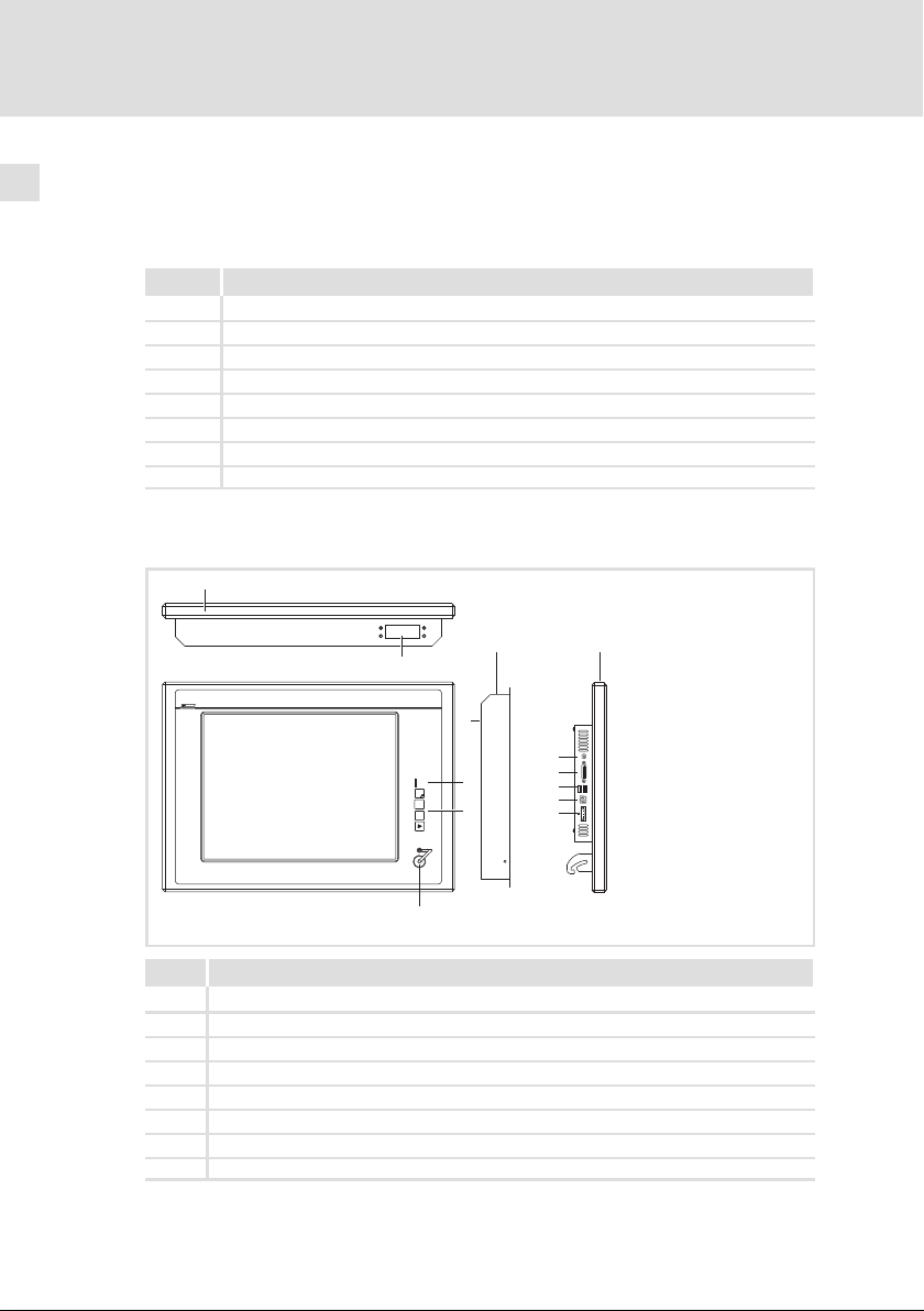
3.2 Bedien− und Anzeigeelemente
0
10
6
7
5
Pos. Beschreibung
Command Station (hier CS 5000 DVI)
Montagewanne
Bildschirm
Status−LEDs (Power, Fail, Status)
Frontseitige Bedienelemente
Frontseitiger USB−Anschluss (Option)
Montagewannen−Anschlussplatte (Option)
Typenschild
1
3
USB-A
USB-B
4
24 V DC
2
+
DVI
0V U
CS50x0−001
MA_CSx0xx DE/EN/FR/ES/IT 2.0
Page 11

4 Installation
4.1 Wichtige Hinweise
Stop!
Empfindlicher Dichtring am Frontrahmen
Während der Montage liegt der Dichtring des Frontrahmens frei
und kann beschädigt werden.
Mögliche Folgen:
ƒ Die in den Technischen Daten genannte Schutzart wird nicht
erreicht.
Schutzmaßnahmen:
ƒ Gehen Sie während der Montage sorgsam mit dem Dichtring um.
ƒ Schützen Sie den Dichtring vor UV−Strahlen.
ƒ Kontrollieren Sie den Dichtring jedes Mal auf Unversehrtheit,
bevor Sie das Gerät montieren.
Stop!
Kurzschluss und statische Entladungen
Das Gerät enthält Bauelemente, die bei Kurzschluss oder statischer
Entladung gefährdet sind.
Mögliche Folgen:
ƒ Das Gerät oder Teile davon werden zerstört.
Schutzmaßnahmen:
ƒ Bei allen Arbeiten am Gerät, immer Spannungsversorgung
abschalten. Dies gilt insbesondere:
– vor dem Anschließen / Abziehen von Steckverbindern.
– vor dem Stecken / Ziehen von Modulen.
ƒ Alle Personen, die Flachbaugruppen handhaben, müssen
ESD−Maßnahmen berücksichtigen.
ƒ Kontakte von Steckverbindern dürfen nicht berührt werden.
ƒ Flachbaugruppen dürfen nur an kontaktfreien Stellen angefasst
werden und nur auf geeigneten Unterlagen abgelegt werden
(z. B. auf ESD−Verpackung oder leitfähigem Schaumstoff).
ƒ Flachbaugruppen dürfen nur in ESD−Verpackungen transportiert
und gelagert werden.
Installation
Wichtige Hinweise
4
MA_CSx0xx DE/EN/FR/ES/IT 2.0
11
Page 12
4
Installation
Montageschritte
Montagewanne demontieren
4.2 Montageschritte
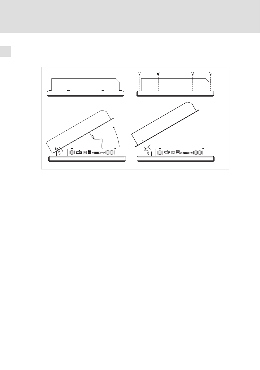
4.2.1 Montagewanne demontieren
0
0
1
0V U
0
2
0V U
CS50xx−004
So gehen Sie vor:
1. Gerät flach, mit der Montagewanne oben, auf eine mit einer Decke
gepolsterte Arbeitsfläche legen.
– Die Arbeitsfläche muss stabil, ausreichend groß und frei von jeglichen
Gegenständen sein. Der Touchscreen wird beschädigt, wenn er auf
Gegenstände, wie zum Beispiel Schrauben, gelegt wird.
2. Schrauben am Montagewannen−Rahmen entfernen.
3. Montagewanne an der Oberseite vorsichtig bis zur Sperre aufklappen
und Erdungskabel abziehen.
4. Montagewanne aus der Einhängung rasten und abnehmen.
Jetzt können Sie die Montagewanne an einem Tragarm ( 13) oder einer Wand
( 15) montieren.
12
MA_CSx0xx DE/EN/FR/ES/IT 2.0
Page 13
Montagewanne an Tragarm montieren
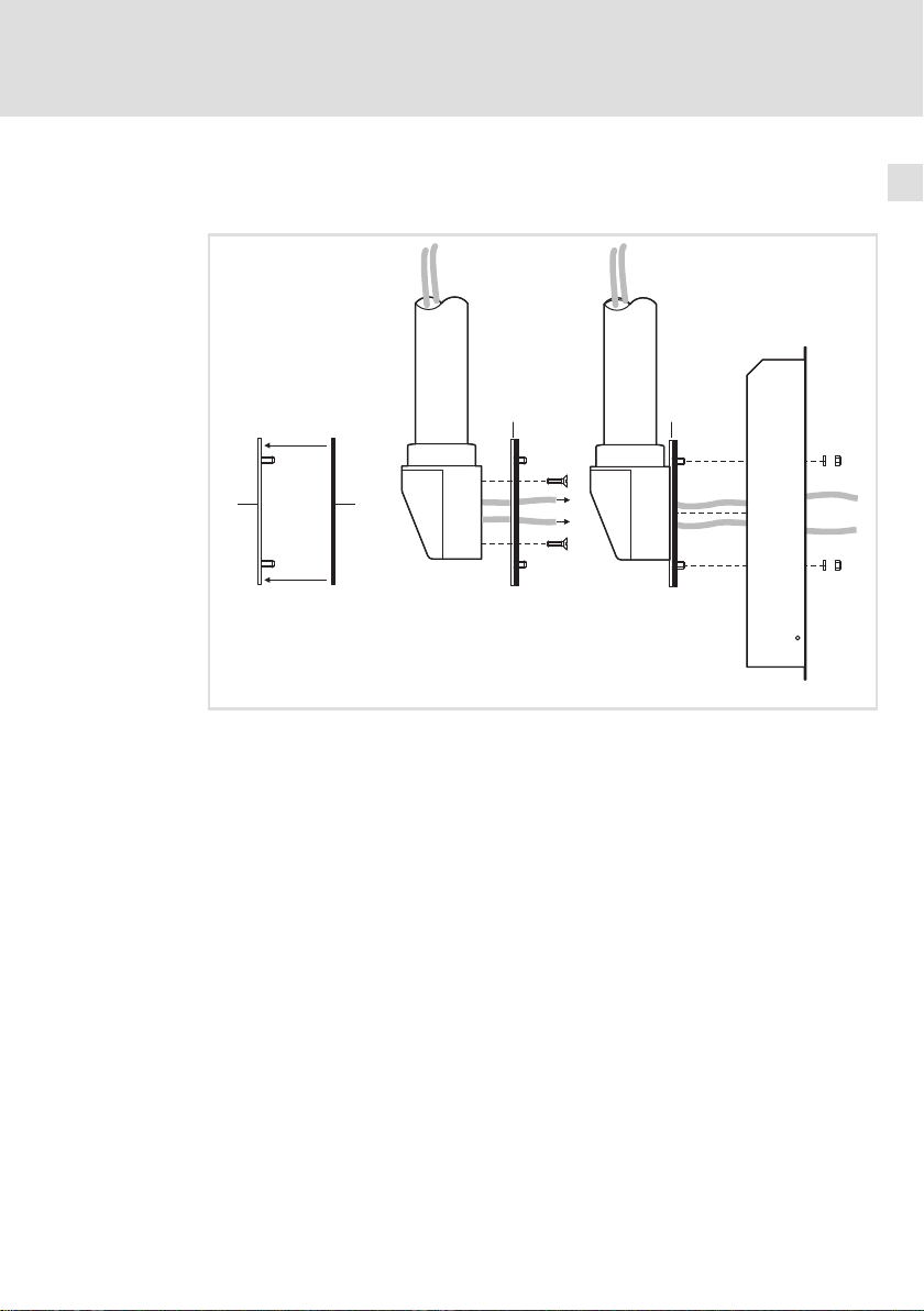
4.2.2 Montagewanne an Tragarm montieren
Ohne Anbauelement
Installation
Montageschritte
4
1
So gehen Sie vor:
1. Tragarmsystem auf fachgerechte Montage und ausreichende
Tragfähigkeit prüfen.
0
3
1
2
1
6
CS57x0−005
– Siehe Tragarm−Dokumentation.
2. Die selbstklebende Dichtung auf die Adapterplatte , auf die Seite mit
den Gewindebolzen, kleben.
3. Die Anschlusskabel aus dem Tragarm ziehen und die Adapterplatte
an den Tragarm schrauben.
– Schrauben siehe Tragarm−Dokumentation.
4. Montagewanne auf die Adapterplatte schrauben.
– 4 Muttern M5 mit Unterlegscheiben Æ 5.3 mm
Jetzt können Sie die Command Station anschließen ( 17).
MA_CSx0xx DE/EN/FR/ES/IT 2.0
13
Page 14
4
Installation
Montageschritte
Montagewanne an Tragarm montieren
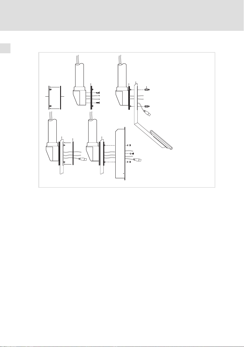
Mit Anbauelement
1
4
3
0
0
1
2
4
4
1
6
5
CS57x0−006
So gehen Sie vor:
1. Tragarmsystem auf fachgerechte Montage und ausreichende
Tragfähigkeit prüfen.
– Siehe Tragarm−Dokumentation.
2. Die selbstklebende Dichtung auf die Adapterplatte , auf die Seite mit
den Gewindebolzen, kleben.
3. Die Anschlusskabel aus dem Tragarm ziehen und die Adapterplatte
an den Tragarm schrauben.
– Schrauben siehe Tragarm−Dokumentation.
4. Anbauelement auf die Gewindebolzen der Adapterplatte schrauben.
– 4 Abstandsbolzen innen/außen M5 x 20 mm
5. Die zweite selbstklebende Dichtung auf das Anbauelement kleben.
6. Montagewanne auf das Anbauelement schrauben.
– 4 Muttern M5 mit Unterlegscheiben Æ 5.3 mm
– 4 Schrauben M5 x 8 mm mit Unterlegscheiben Æ 5.3 mm
Jetzt können Sie die Command Station anschließen ( 17).
14
MA_CSx0xx DE/EN/FR/ES/IT 2.0
Page 15
Montagewanne an Wand montieren
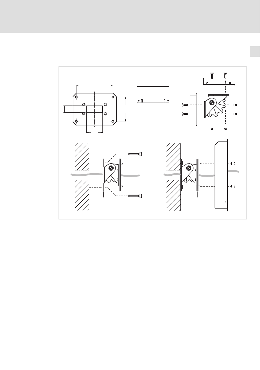
4.2.3 Montagewanne an Wand montieren
Ohne Anbauelement
Installation
Montageschritte
4
29.5
1
160
0
106
2
2
0
3
70
6
3 3
CS57x0−010
So gehen Sie vor:
1. Wand für die Montage der Wandhalterung vorbereiten.
– Der Montageort und das Montagematerial muss die mechanische
Verbindung dauerhaft gewährleisten.
2. Die selbstklebende Dichtung auf die Adapterplatte , auf die Seite mit
den Gewindebolzen, kleben.
3. Wandhalterung und die Adapterplatte an den Schwenkadapter
schrauben.
– 2 x 4 Senkkopfschrauben M5 x 16 mm mit Unterlegscheiben Æ 5.3 mm
und Muttern M5
4. Die Anschlusskabel durch den Schwenkadapter ziehen und den
Schwenkadapter an die Wand schrauben.
5. Montagewanne an den Schwenkadapter schrauben.
– 4 Muttern M5 mit Unterlegscheiben Æ 5.3 mm
Jetzt können Sie die Command Station anschließen ( 17).
MA_CSx0xx DE/EN/FR/ES/IT 2.0
15
Page 16
4
Installation
Montageschritte
Montagewanne an Wand montieren
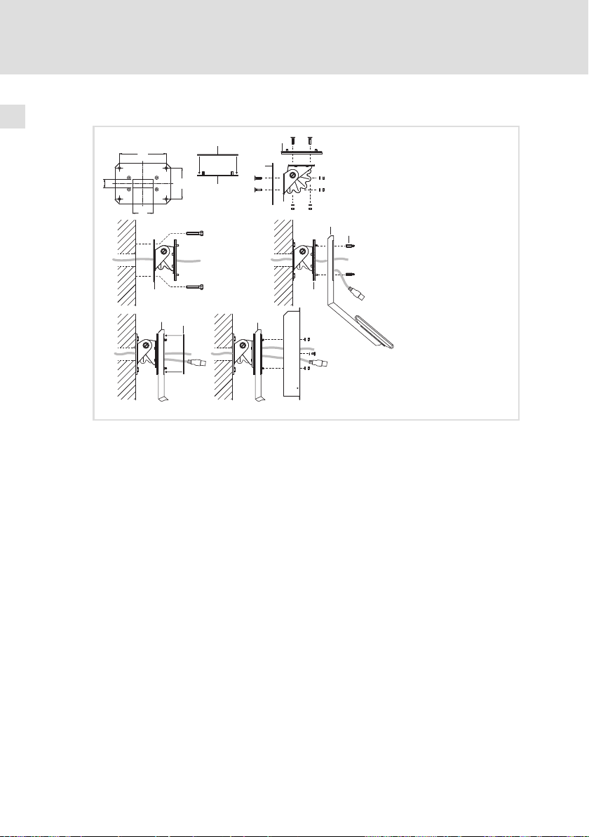
Mit Anbauelement
160
0
29.5
70
3
106
4
1
1
2
2
0
3
4
4
5
3
6
CS57x0−011
So gehen Sie vor:
1. Wand für die Montage der Wandhalterung vorbereiten.
– Der Montageort und das Montagematerial muss die mechanische
Verbindung dauerhaft gewährleisten.
2. Die selbstklebende Dichtung auf die Adapterplatte , auf die Seite mit
den Gewindebolzen, kleben.
3. Wandhalterung und die Adapterplatte an den Schwenkadapter
schrauben.
– 2 x 4 Senkkopfschrauben M5 x 16 mm mit Unterlegscheiben Æ 5.3 mm
und Muttern M5
4. Die Anschlusskabel durch den Schwenkadapter ziehen und den
Schwenkadapter an die Wand schrauben.
5. Anbauelement auf die Gewindebolzen des Schwenkadapters
schrauben.
– 4 Abstandsbolzen innen/außen M5 x 20 mm
6. Die zweite selbstklebende Dichtung auf das Anbauelement kleben.
7. Montagewanne auf das Anbauelement schrauben.
– 4 Muttern M5 mit Unterlegscheiben Æ 5.3 mm
– 4 Schrauben M5 x 8 mm mit Unterlegscheiben Æ 5.3 mm
Jetzt können Sie die Command Station anschließen ( 17).
16
MA_CSx0xx DE/EN/FR/ES/IT 2.0
Page 17
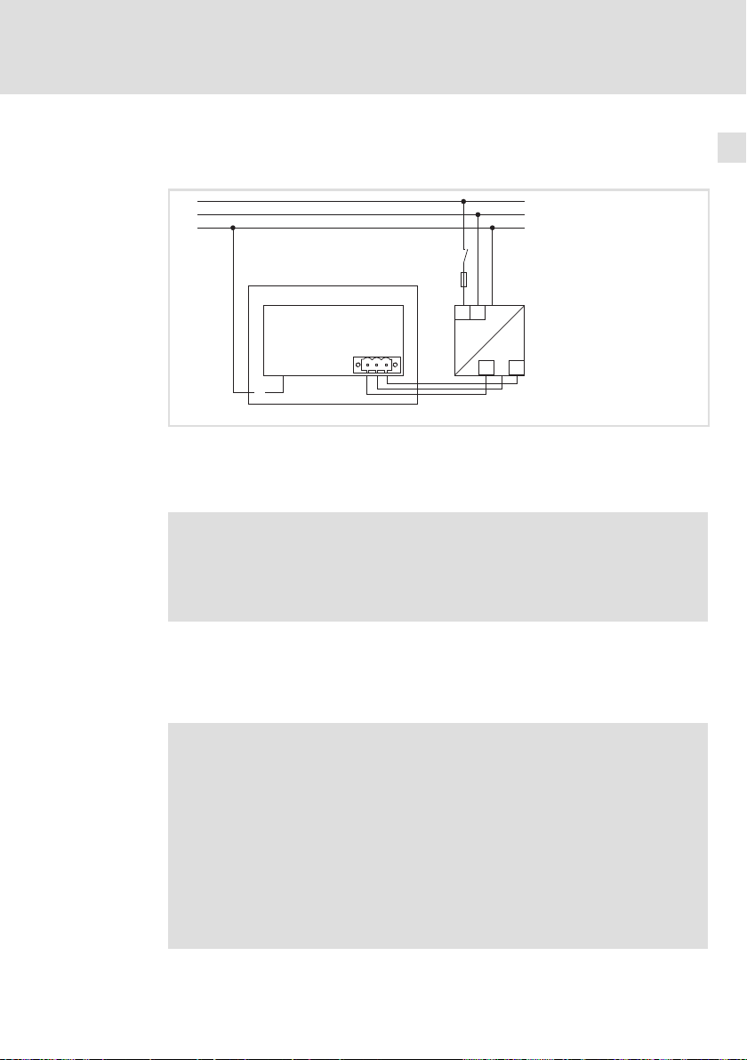
4.3 Elektrische Installation
Anschlussplan Versorgung
L1
N
PE
0
1
+
+
Montagewanne
Bildschirm
Netzteil
Hinweis!
Beachten Sie die maximal zulässige Eingangsspannung.
Sichern Sie das Gerät eingangsseitig fachgerecht gegen
Spannungsschwankungen und −spitzen ab.
0 V
PE +24V
Installation
Elektrische Installation
S
F
N
L1
+
~=
2
+
+24
0V
4
CS50x0−021
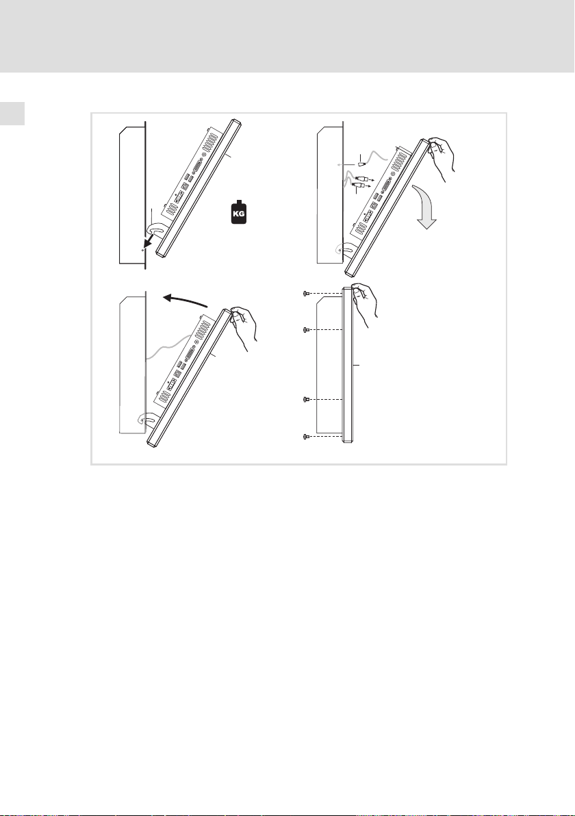
Versorgung und Peripheriegeräte anschließen
Zum Anschließen der Versorgung und der Peripherie muss der Bildschirm in die
Montagewanne eingehängt und abgeklappt werden.
Stop!
Bildschirm kann herunterfallen
Wenn der Bildschirm nicht mit der Montagewanne verschraubt ist,
kann er herunterfallen.
Mögliche Folgen:
ƒ Der Bildschirm wird beschädigt.
ƒ Verletzungen durch das herunterfallende Gerät.
Schutzmaßnahmen:
ƒ Bildschirm gegen Herunterfallen sichern.
MA_CSx0xx DE/EN/FR/ES/IT 2.0
17
Page 18
4
Installation
Elektrische Installation
1
0
0V U
2
}
max. 12 kg
3
+
}
4
0V U
}
}
00
0V U
So gehen Sie vor:
1. Bildschirm mit der Einhängung in die Montagewanne setzen und
während der folgenden Arbeitsschritte gegen Herunterfallen sichern.
2. Anschlusskabel stecken.
– PE−Anschlusskabel an der Montagewanne stecken
– Sonstige Anschlusskabel stecken (Versorgung, DVI, USB).
3. Bildschirm einklappen.
4. Bildschirm an der Montagewanne verschrauben.
Immer alle Schrauben montieren.
1
1
CS50x0−012
18
MA_CSx0xx DE/EN/FR/ES/IT 2.0
Page 19

Contents i
1 About this documentation 20. . . . . . . . . . . . . . . . . . . . . . . . . . . . . . . . . . . . . . . . . .
1.1 Notes used 20. . . . . . . . . . . . . . . . . . . . . . . . . . . . . . . . . . . . . . . . . . . . . . . .
3 Safety instructions 21. . . . . . . . . . . . . . . . . . . . . . . . . . . . . . . . . . . . . . . . . . . . . . . .
3.1 General safety information 21. . . . . . . . . . . . . . . . . . . . . . . . . . . . . . . . . . .
3.2 Safety instructions for the installation according to UL 22. . . . . . . . . . . .
4 Product description 26. . . . . . . . . . . . . . . . . . . . . . . . . . . . . . . . . . . . . . . . . . . . . . .
4.1 Scope of supply 26. . . . . . . . . . . . . . . . . . . . . . . . . . . . . . . . . . . . . . . . . . . .
4.2 Controls and displays 26. . . . . . . . . . . . . . . . . . . . . . . . . . . . . . . . . . . . . . . .
5 Installation 27. . . . . . . . . . . . . . . . . . . . . . . . . . . . . . . . . . . . . . . . . . . . . . . . . . . . . .
5.1 Important notes 27. . . . . . . . . . . . . . . . . . . . . . . . . . . . . . . . . . . . . . . . . . . .
5.3 Mounting steps 28. . . . . . . . . . . . . . . . . . . . . . . . . . . . . . . . . . . . . . . . . . . .
5.3.1 Removing the mounting frame 28. . . . . . . . . . . . . . . . . . . . . .
5.3.2 Fixing the mounting frame to the support arm 29. . . . . . . . .
5.3.3 Fixing the mounting frame to the wall 31. . . . . . . . . . . . . . . .
5.4 Electrical installation 33. . . . . . . . . . . . . . . . . . . . . . . . . . . . . . . . . . . . . . . .
MA_CSx0xx DE/EN/FR/ES/IT 2.0
19
Page 20
1
About this documentation
Notes used
1 About this documentation
0Fig. 0Tab. 0
1.1 Notes used
The following pictographs and signal words are used in this documentation to
indicate dangers and important information:
Safety instructions
Structure of safety instructions:
Danger!
(characterises the type and severity of danger)
Note
(describes the danger and gives information about how to prevent
dangerous situations)
Pictograph and signal word Meaning
Danger!
Danger!
Stop!
Application notes
Danger of personal injury through dangerous electrical
voltage.
Reference to an imminent danger that may result in
death or serious personal injury if the corresponding
measures are not taken.
Danger of personal injury through a general source of
danger.
Reference to an imminent danger that may result in
death or serious personal injury if the corresponding
measures are not taken.
Danger of property damage.
Reference to a possible danger that may result in
property damage if the corresponding measures are not
taken.
20
Pictograph and signal word Meaning
Note!
Tip!
Important note to ensure troublefree operation
Useful tip for simple handling
Reference to another documentation
MA_CSx0xx DE/EN/FR/ES/IT 2.0
Page 21

2 Safety instructions
2.1 General safety information
For your own safety
Danger!
Disregarding the following basic safety measures may lead to
severe personal injury and damage to material assets!
ƒ Lenze drive and automation components ...
... must only be used for the intended purpose.
... must never be operated if damaged.
... must never be subjected to technical modifications.
... must never be operated unless completely assembled.
... must never be operated without the covers/guards.
... can − depending on their degree of protection − have live, movable or
rotating parts during or after operation. Surfaces can be hot.
ƒ For Lenze drive and automation components ...
... only use approved accessories.
... only use original manufacturer spare parts.
ƒ All specifications of the corresponding enclosed documentation must be
observed.
This is vital for a safe and trouble−free operation and for achieving the
specified product features.
The procedural notes and circuit details provided in this document are
proposals which the user must check for suitability for his application. The
manufacturer does not accept any liability for the suitability of the specified
procedures and circuit proposals.
ƒ Only qualified skilled personnel are permitted to work with or on Lenze
drive and automation components.
According to IEC 60364 or CENELEC HD 384, these are persons ...
... who are familiar with the installation, assembly, commissioning and
operation of the product,
... possess the appropriate qualifications for their work,
... and are acquainted with and can apply all the accident prevent
regulations, directives and laws applicable at the place of use.
Safety instructions
General safety information
2
MA_CSx0xx DE/EN/FR/ES/IT 2.0
21
Page 22

2
2.2 Safety instructions for the installation according to UL
Safety instructions
Safety instructions for the installation according to UL
Original − English
Approval
Underwriter Laboratories (UL), UL508 and CSA C22.2 No. 142−M1987, (UL File
Number E236341)
22
MA_CSx0xx DE/EN/FR/ES/IT 2.0
Page 23

Safety instructions
Safety instructions for the installation according to UL
Ratings
ƒ Input 24 V DC, max. 65 W (65 VA)
ƒ Max. ambient temperature 40 °C
ƒ Environmental ratings: Type 1 Enclosure
ƒ Optional communication ratings:
– RS232−Connection: max. 3 A
– USB−Connection, PS/2−Connection: max. 1 A
– LAN−Connection: Standard ISDN or RJ45
– VGA−Connection, FBAS−Connection, DVI−Connector, DPL−Connection:
max. 4 A
– External Power Supply for DVI/USB Extender: max. 4 A
– Video−DSUB Connection for DVI/USB Extender: max. 4 A
– Data−DSUB Connection for DVI/USB Extender : max. 4 A
Warnings!
Conditions of acceptability
ƒ These devices are evaluated to meet environmental UL Type 1
Enclosure requirements, when all openings in the enclosure back
are closed (filled) by devices with suitable environmental type
ratings. This may be achieved by use of appropriate supporting
beam (support arm system), with suitable environmental ratings
or equivalent means.
ƒ Models CS5710 IPC and CS5710 DVI are rated for environmental
UL Type 1 Enclosure, when openings in the front are closed with
suitable devices (e.g. buttons, emergency off button, etc.).
ƒ The effects of condensation or high humidity shall be reduced by
the application of heat through continuous energization of the
equipment, with interruptions such that cooling to the point of
condensation does not occur.
ƒ The devices are intended for the use in a pollution degree 2 or
controlled environment only.
Field Wiring Markings
Wiring Terminal MSTB 2,5/3−STF−5,08:
ƒ Use Copper Wire only.
ƒ AWG 18 ... AWG 12 (0.82 mm
ƒ Torque 5...7 lb−in (0.5 ... 0.6 Nm)
2
... 3.3 mm2)
2
MA_CSx0xx DE/EN/FR/ES/IT 2.0
23
Page 24

2
Safety instructions
Safety instructions for the installation according to UL
Original − French
Homologation
Underwriter Laboratories (UL), UL508 et CSA C22.2 n° 142−M1987, (n° de dossier
UL E236341)
24
MA_CSx0xx DE/EN/FR/ES/IT 2.0
Page 25

Safety instructions
Safety instructions for the installation according to UL
Caractéristiques assignées
ƒ Entrée 24 V CC, maximum 65 W (65 VA)
ƒ Température ambiante maximale : 40 °C
ƒ Evaluation environnementale : coffret de type 1
ƒ Caractéristiques de communication assignées (option) :
– Port RS232 : maximum 3 A
– Port USB, port PS/2 : maximum 1 A
– Port LAN : RNIS standard ou RJ45
– Port VGA, port FBAS, connecteur DVI, port DPL : maximum 4 A
– Alimentation externe pour carte d’extension DVI/USB : maximum 4 A
– Port vidéo DSUB pour carte d’extension DVI/USB : maximum 4 A
– Port de données DSUB pour carte d’extension DVI/USB : maximum 4 A
Warnings!
Conditions d’acceptabilité
ƒ Ces équipements sont évalués en vue de déterminer la
conformité aux exigences environnementales UL pour un coffret
de type 1, toutes les ouvertures à l’arrière du coffret étant
fermées (obturées) par des dispositifs appropriés. Pour cela, il
convient d’utiliser une traverse de support (système à bras
porteur) appropriée ou un système équivalent.
ƒ Les modèles CS5710 IPC et CS5710 DVI sont conçus pour un
coffret de type 1 (classification environnementale UL), toutes les
ouvertures à l’avant du coffret étant fermées par les dispositifs
adaptés (touches de commande, bouton d’arrêt d’urgence, etc.).
ƒ Les effets de la condensation ou d’une humidité importante
peuvent être compensés par la chaleur générée par une mise
sous tension continue de l’équipement. Les interruptions doivent
être contrôlées de façon à ce que le point de condensation ne soit
pas atteint durant les phases de refroidissement.
ƒ Les équipements sont destinés exclusivement à être utilisés dans
un environnement contrôlé, caractérisé par le degré de pollution
2.
Marquage du câblage à pied d’oeuvre
Bornier de câblage MSTB 2,5/3−STF−5,08 :
ƒ Utiliser exclusivement des conducteurs en cuivre.
ƒ AWG 18 ... AWG 12 (0,82 mm
ƒ Couple de 5 à 7 lb−in (0,5 ... 0,6 Nm)
2
... 3,3 mm2)
2
MA_CSx0xx DE/EN/FR/ES/IT 2.0
25
Page 26

3
Status
F1
Fail
+
-
F3
F2
Power
Product description
Scope of supply
3 Product description
3.1 Scope of supply
Quantity Name
1 Monitor panel
1 Connection plug for voltage supply
1 DVI−D cable (length 2 m)
1 USB cable (length 2 m)
1 Fixing adapter (option)
1 DVD "PC based Automation"
1 Test report
1 Device pass card
3.2 Controls and displays
0
26
6
5
Pos. Description
Command Station (here CS 5000 DVI)
Mounting frame
Screen
Status LEDs (Power, Fail, Status)
Front face control elements
Front face USB port (option)
Mounting frame connecting plate (option)
Nameplate
1
2
7
+
3
4
DVI
USB-A
USB-B
24 V DC
0V U
CS50x0−001
MA_CSx0xx DE/EN/FR/ES/IT 2.0
Page 27

4 Installation
4.1 Important notes
Stop!
Sensitive front frame gasket
During mounting, the gasket of the front frame is exposed and can
be damaged.
Possible consequences:
ƒ The degree of protection provided by the enclosure mentioned in
the technical data is not attained.
Protective measures:
ƒ Handle the gasket with care during mounting.
ƒ Protect the gasket against ultraviolet rays.
ƒ Each time before you mount the device, check whether the
gasket is intact.
Stop!
Short circuit and static discharge
The device contains components which are endangered in the case
of short circuit or static discharge.
Possible consequences:
ƒ The device or parts of it will be destroyed.
Protective measures:
ƒ Always switch off the voltage supply when working on the
device. This particularly applies:
– Before connecting / disconnecting connectors.
– Before plugging in / plugging out modules.
ƒ All persons handling printed circuit boards have to take account
of ESD measures.
ƒ Contacts of plug connectors must not be touched.
ƒ Printed circuit boards may be touched only at places free from
electrical contacts and may be placed only on appropriate
materials (e.g. on ESD packaging or conductive foam material).
ƒ Printed circuit boards may only be transported and stored in ESD
packaging.
Installation
Important notes
4
MA_CSx0xx DE/EN/FR/ES/IT 2.0
27
Page 28

4
Installation
Mounting steps
Removing the mounting frame
4.2 Mounting steps
4.2.1 Removing the mounting frame
0
0
1
0V U
0
2
0V U
CS50xx−004
How to proceed:
1. Lay the device flat, with the mounting frame upwards, on a work
surface cushioned with a blanket.
– The work surface must be stable, sufficiently large, and free of any
objects. The touchscreen will be damaged when being laid on objects as
for instance screws.
2. Remove screws from the mounting frame.
3. Open the mounting frame at the top carefully until it locks and pull the
earthing cable .
4. Unlatch the mounting frame from the attachment and remove it.
Now you can mount the mounting frame to a support arm ( 29) or to a wall.
( 31)
28
MA_CSx0xx DE/EN/FR/ES/IT 2.0
Page 29

Fixing the mounting frame to the support arm
4.2.2 Fixing the mounting frame to the support arm
Without add−on component
Installation
Mounting steps
4
1
How to proceed:
1. Check support arm system for professional mounting and sufficient
carrying capacity.
0
3
1
2
1
6
CS57x0−005
– See support arm documentation.
2. Stick the self−adhesive seal on the adapter plate on the side with the
threaded bolts.
3. Pull the connecting cables out of the support arm and screw the
adapter plate to the support arm .
– For screws see support arm documentation.
4. Screw the mounting frame to the adapter plate .
– 4 nuts M5 with washers Æ 5.3 mm
Now you can connect the Command Station ( 33).
MA_CSx0xx DE/EN/FR/ES/IT 2.0
29
Page 30

4
Installation
Mounting steps
Fixing the mounting frame to the support arm
With add−on component
1
4
3
0
0
1
2
4
4
1
6
5
CS57x0−006
How to proceed:
1. Check support arm system for professional mounting and sufficient
carrying capacity.
– See support arm documentation.
2. Stick the self−adhesive seal on the adapter plate on the side with the
threaded bolts.
3. Pull the connecting cables out of the support arm and screw the
adapter plate to the support arm .
– For screws see support arm documentation.
4. Screw the add−on component to the threaded bolts of the adapter plate
.
– 4 spacer bolts on the inside/outside M5 x 20 mm
5. Stick the second self−adhesive seal on the add−on component .
6. Screw the mounting frame to the add−on component .
– 4 nuts M5 with washers Æ 5.3 mm
– 4 screws M5 x 8 mm with washers Æ 5.3 mm
Now you can connect the Command Station ( 33).
30
MA_CSx0xx DE/EN/FR/ES/IT 2.0
Page 31

Fixing the mounting frame to the wall
4.2.3 Fixing the mounting frame to the wall
Without add−on component
Installation
Mounting steps
4
29.5
1
160
0
106
2
2
0
3
70
6
3 3
CS57x0−010
How to proceed:
1. Prepare the wall for mounting the wall bracket .
– The mounting location and the installation material must provide for a
permanent mechanical connection.
2. Stick the self−adhesive seal on the adapter plate on the side with the
threaded bolts.
3. Screw the wall bracket and the adapter plate to the swivel adapter .
– 2 x 4 countersunk head screws M5 x 16 mm with washers Æ 5.3 mm
and nuts M5
4. Pull the connecting cable through the swivel adapter and screw the
swivel adapter to the wall.
5. Screw the mounting frame to the swivel adapter .
– 4 nuts M5 with washers Æ 5.3 mm
Now you can connect the Command Station ( 33).
MA_CSx0xx DE/EN/FR/ES/IT 2.0
31
Page 32

4
Installation
Mounting steps
Fixing the mounting frame to the wall
With add−on component
160
0
29.5
70
3
106
4
1
1
2
2
0
3
4
4
5
3
6
CS57x0−011
How to proceed:
1. Prepare the wall for mounting the wall bracket .
– The mounting location and the installation material must provide for a
permanent mechanical connection.
2. Stick the self−adhesive seal on the adapter plate on the side with the
threaded bolts.
3. Screw the wall bracket and the adapter plate to the swivel adapter .
– 2 x 4 countersunk head screws M5 x 16 mm with washers Æ 5.3 mm
and nuts M5
4. Pull the connecting cable through the swivel adapter and screw the
swivel adapter to the wall.
5. Screw the add−on component to the threaded bolts of the swivel
adapter .
– 4 spacer bolts on the inside/outside M5 x 20 mm
6. Stick the second self−adhesive seal on the add−on component .
7. Screw the mounting frame to the add−on component .
– 4 nuts M5 with washers Æ 5.3 mm
– 4 screws M5 x 8 mm with washers Æ 5.3 mm
Now you can connect the Command Station ( 33).
32
MA_CSx0xx DE/EN/FR/ES/IT 2.0
Page 33

4.3 Electrical installation
Terminal diagram supply
L1
N
PE
0
1
+
+
Mounting frame
Screen
Power supply unit
Note!
Observe the max. permissible input voltage.
Professionally fuse the device on the input side against voltage
variations and voltage peaks.
0 V
PE +24V
Installation
Electrical installation
S
F
N
L1
+
~=
2
+
+24
0V
4
CS50x0−021
Connecting the supply and peripheral devices
For connecting the supply and the peripherals, the screen must be fitted into the
mounting frame and hinged down.
Stop!
Screen may fall down
If the screen is not screwed together with the mounting frame it
may fall down.
Possible consequences:
ƒ The screen is damaged.
ƒ Injuries by the falling device.
Protective measures:
ƒ Secure screen against falling down.
MA_CSx0xx DE/EN/FR/ES/IT 2.0
33
Page 34

4
Installation
Electrical installation
1
0
0V U
2
}
max. 12 kg
3
+
}
4
0V U
}
}
00
0V U
How to proceed:
1. Place screen in the mounting frame using the attachment and
secure it against falling down during the following worksteps.
2. Plug in the connection cable .
– Plug in the PE connection cable on the mounting frame
– Plug in other connection cables (supply, DVI, USB).
3. Retract screen.
4. Screw screen to the mounting frame.
Always fit all screws.
1
1
CS50x0−012
34
MA_CSx0xx DE/EN/FR/ES/IT 2.0
Page 35

Sommaire i
1 Présentation du document 36. . . . . . . . . . . . . . . . . . . . . . . . . . . . . . . . . . . . . . . . .
1.1 Consignes utilisées 36. . . . . . . . . . . . . . . . . . . . . . . . . . . . . . . . . . . . . . . . .
3 Consignes de sécurité 37. . . . . . . . . . . . . . . . . . . . . . . . . . . . . . . . . . . . . . . . . . . . . .
3.1 Consignes générales de sécurité 37. . . . . . . . . . . . . . . . . . . . . . . . . . . . . . .
3.2 Consignes de sécurité pour l’installation selon UL 38. . . . . . . . . . . . . . . .
4 Description du produit 42. . . . . . . . . . . . . . . . . . . . . . . . . . . . . . . . . . . . . . . . . . . . .
4.1 Equipement livré 42. . . . . . . . . . . . . . . . . . . . . . . . . . . . . . . . . . . . . . . . . . .
4.2 Eléments de commande et d’affichage 42. . . . . . . . . . . . . . . . . . . . . . . . .
5 Installation 43. . . . . . . . . . . . . . . . . . . . . . . . . . . . . . . . . . . . . . . . . . . . . . . . . . . . . .
5.1 Remarques importantes 43. . . . . . . . . . . . . . . . . . . . . . . . . . . . . . . . . . . . .
5.3 Opérations de montage 45. . . . . . . . . . . . . . . . . . . . . . . . . . . . . . . . . . . . . .
5.3.1 Démontage du châssis de montage 45. . . . . . . . . . . . . . . . . . .
5.3.2 Montage du châssis sur bras porteur 46. . . . . . . . . . . . . . . . . .
5.3.3 Montage mural du châssis 48. . . . . . . . . . . . . . . . . . . . . . . . . .
5.4 Installation électrique 50. . . . . . . . . . . . . . . . . . . . . . . . . . . . . . . . . . . . . . .
MA_CSx0xx DE/EN/FR/ES/IT 2.0
35
Page 36

1
Présentation du document
Consignes utilisées
1 Présentation du document
0Fig. 0Tab. 0
1.1 Consignes utilisées
Pour indiquer des risques et des informations importantes, la présente
documentation utilise les mots et pictogrammes suivants :
Consignes de sécurité
Présentation des consignes de sécurité
Danger !
(Le pictogramme indique le type de risque.)
Explication
(L’explication décrit le risque et les moyens de l’éviter.)
Pictogramme et mot associé Explication
Danger !
Danger !
Stop !
Consignes d’utilisation
Situation dangereuse pour les personnes en raison
d’une tension électrique élevée
Indication d’un danger imminent qui peut avoir pour
conséquences des blessures mortelles ou très graves en
cas de non−respect des consignes de sécurité
correspondantes
Situation dangereuse pour les personnes en raison d’un
danger d’ordre général
Indication d’un danger imminent qui peut avoir pour
conséquences des blessures mortelles ou très graves en
cas de non−respect des consignes de sécurité
correspondantes
Risques de dégâts matériels
Indication d’un risque potentiel qui peut avoir pour
conséquences des dégâts matériels en cas de
non−respect des consignes de sécurité correspondantes
36
Pictogramme et mot associé Explication
Remarque
importante !
Conseil !
Remarque importante pour assurer un fonctionnement
correct
Conseil utile pour faciliter la mise en uvre
Renvoi à une autre documentation
MA_CSx0xx DE/EN/FR/ES/IT 2.0
Page 37

2 Consignes de sécurité
2.1 Consignes générales de sécurité
Conseils pour assurer votre sécurité
Danger !
Le non−respect des consignes fondamentales de sécurité suivantes
peut entraîner des blessures et des dommages matériels graves.
ƒ Les composants d’entraînement et d’automatisation Lenze ...
... doivent exclusivement être utilisés conformément à leur fonction.
... ne doivent jamais être mis en service si des dommages sont décelés.
... ne doivent jamais être modifiés d’un point de vue technique.
... ne doivent jamais être mis en service s’ils ne sont pas montés
intégralement.
... ne doivent jamais être mis en service sans le capot obligatoire.
... peuvent − selon l’indice de protection − contenir des pièces sous tension, en
mouvement ou en rotation. Les surfaces peuvent être brûlantes.
ƒ Pour les composants d’entraînement et d’automatisation Lenze ...
... utiliser uniquement les accessoires homologués pour le produit.
... utiliser uniquement les pièces détachées d’origine proposées par le
constructeur.
ƒ Respecter les consignes et les indications contenues dans la
documentation concernée.
Il s’agit de la condition préalable pour garantir un fonctionnement sûr et
fiable et pour obtenir les caractéristiques du produit indiquées.
Les procédures à suivre et les plans de raccordement fournis constituent des
recommandations dont l’adéquation avec l’application concernée doit être
vérifiée. Lenze n’assumera aucune responsabilité pour les dommages liés à
un problème d’adéquation des procédures et plans de raccordements
indiqués.
ƒ Les travaux réalisés avec et au niveau des composants d’entraînement et
d’automatisation Lenze ne doivent être exécutés que par un personnel
qualifié et habilité.
Selon les normes CEI 60364 ou CENELEC HD 384, ces personnes doivent ...
... connaître parfaitement l’installation, le montage, la mise en service et le
fonctionnement du produit.
... posséder les qualifications appropriées pour l’exercice de leur activité.
... connaître toutes les prescriptions pour la prévention d’accidents,
directives et lois applicables sur le lieu d’utilisation et être en mesure de les
appliquer.
Consignes de sécurité
Consignes générales de sécurité
2
MA_CSx0xx DE/EN/FR/ES/IT 2.0
37
Page 38

2
Consignes de sécurité
Consignes de sécurité pour l’installation selon U
L
2.2 Consignes de sécurité pour l’installation selon U
Original − Anglais
Approval
Underwriter Laboratories (UL), UL508 and CSA C22.2 No. 142−M1987, (UL File
Number E236341)
L
38
MA_CSx0xx DE/EN/FR/ES/IT 2.0
Page 39

Consignes de sécurité
Consignes de sécurité pour l’installation selon U
Ratings
ƒ Input 24 V DC, max. 65 W (65 VA)
ƒ Max. ambient temperature 40 °C
ƒ Environmental ratings: Type 1 Enclosure
ƒ Optional communication ratings:
– RS232−Connection: max. 3 A
– USB−Connection, PS/2−Connection: max. 1 A
– LAN−Connection: Standard ISDN or RJ45
– VGA−Connection, FBAS−Connection, DVI−Connector, DPL−Connection:
max. 4 A
– External Power Supply for DVI/USB Extender: max. 4 A
– Video−DSUB Connection for DVI/USB Extender: max. 4 A
– Data−DSUB Connection for DVI/USB Extender : max. 4 A
Warnings!
Conditions of acceptability
ƒ These devices are evaluated to meet environmental UL Type 1
Enclosure requirements, when all openings in the enclosure back
are closed (filled) by devices with suitable environmental type
ratings. This may be achieved by use of appropriate supporting
beam (support arm system), with suitable environmental ratings
or equivalent means.
ƒ Models CS5710 IPC and CS5710 DVI are rated for environmental
UL Type 1 Enclosure, when openings in the front are closed with
suitable devices (e.g. buttons, emergency off button, etc.).
ƒ The effects of condensation or high humidity shall be reduced by
the application of heat through continuous energization of the
equipment, with interruptions such that cooling to the point of
condensation does not occur.
ƒ The devices are intended for the use in a pollution degree 2 or
controlled environment only.
Field Wiring Markings
Wiring Terminal MSTB 2,5/3−STF−5,08:
ƒ Use Copper Wire only.
ƒ AWG 18 ... AWG 12 (0.82 mm
ƒ Torque 5...7 lb−in (0.5 ... 0.6 Nm)
2
... 3.3 mm2)
2
L
MA_CSx0xx DE/EN/FR/ES/IT 2.0
39
Page 40

2
Consignes de sécurité
Consignes de sécurité pour l’installation selon U
Original − Français
Homologation
Underwriter Laboratories (UL), UL508 et CSA C22.2 n° 142−M1987, (n° de dossier
UL E236341)
L
40
MA_CSx0xx DE/EN/FR/ES/IT 2.0
Page 41

Consignes de sécurité
Consignes de sécurité pour l’installation selon U
Caractéristiques assignées
ƒ Entrée 24 V CC, maximum 65 W (65 VA)
ƒ Température ambiante maximale : 40 °C
ƒ Evaluation environnementale : coffret de type 1
ƒ Caractéristiques de communication assignées (option) :
– Port RS232 : maximum 3 A
– Port USB, port PS/2 : maximum 1 A
– Port LAN : RNIS standard ou RJ45
– Port VGA, port FBAS, connecteur DVI, port DPL : maximum 4 A
– Alimentation externe pour carte d’extension DVI/USB : maximum 4 A
– Port vidéo DSUB pour carte d’extension DVI/USB : maximum 4 A
– Port de données DSUB pour carte d’extension DVI/USB : maximum 4 A
L
Warnings!
Conditions d’acceptabilité
ƒ Ces équipements sont évalués en vue de déterminer la
conformité aux exigences environnementales UL pour un coffret
de type 1, toutes les ouvertures à l’arrière du coffret étant
fermées (obturées) par des dispositifs appropriés. Pour cela, il
convient d’utiliser une traverse de support (système à bras
porteur) appropriée ou un système équivalent.
ƒ Les modèles CS5710 IPC et CS5710 DVI sont conçus pour un
coffret de type 1 (classification environnementale UL), toutes les
ouvertures à l’avant du coffret étant fermées par les dispositifs
adaptés (touches de commande, bouton d’arrêt d’urgence, etc.).
ƒ Les effets de la condensation ou d’une humidité importante
peuvent être compensés par la chaleur générée par une mise
sous tension continue de l’équipement. Les interruptions doivent
être contrôlées de façon à ce que le point de condensation ne soit
pas atteint durant les phases de refroidissement.
ƒ Les équipements sont destinés exclusivement à être utilisés dans
un environnement contrôlé, caractérisé par le degré de pollution
2.
Marquage du câblage à pied d’oeuvre
Bornier de câblage MSTB 2,5/3−STF−5,08 :
ƒ Utiliser exclusivement des conducteurs en cuivre.
ƒ AWG 18 ... AWG 12 (0,82 mm
ƒ Couple de 5 à 7 lb−in (0,5 ... 0,6 Nm)
2
... 3,3 mm2)
2
MA_CSx0xx DE/EN/FR/ES/IT 2.0
41
Page 42

3
Status
F1
Fail
+
-
F3
F2
Power
Description du produit
Equipement livré
3 Description du produit
3.1 Equipement livré
Quantité Désignation
1 Monitor Panel (écran de supervision)
1 Connecteur d’alimentation
1 Câble DVI−D (longueur : 2 m)
1 Câble USB (longueur : 2 m)
1 Adaptateur de fixation (option)
1 DVD "PC based Automation"
1 Rapport d’essai
1 Carte d’identification de l’appareil
3.2 Eléments de commande et d’affichage
0
42
6
1
7
+
3
4
DVI
USB-A
USB-B
24 V DC
5
Pos. Description
Command Station (unité de commande) (ici : CS 5000 DVI)
Châssis de montage
Ecran
LEDs d’état (Power, Fail, Status)
Eléments de commande sur la face avant
Port USB sur la face avant (option)
Plaque de raccordement du châssis de montage (option)
Plaque signalétique
2
0V U
CS50x0−001
MA_CSx0xx DE/EN/FR/ES/IT 2.0
Page 43

4 Installation
4.1 Remarques importantes
Stop !
Joint d’étanchéité fragile sur cadre avant
Pendant les opérations de montage, le joint d’étanchéité du cadre
avant n’est pas protégé et risque alors d’être endommagé.
Risques encourus :
ƒ L’indice de protection indiqué sous "Spécifications techniques"
n’est pas atteint.
Mesures de protection :
ƒ Pendant le montage, manipuler le joint d’étanchéité avec soin.
ƒ Protéger le joint d’étancheité contre les rayons UV.
ƒ Avant chaque montage de l’appareil, vérifier l’intégrité du joint
d’étanchéité.
Installation
Remarques importantes
4
MA_CSx0xx DE/EN/FR/ES/IT 2.0
43
Page 44

4
Installation
Remarques importantes
Stop !
Court−circuits et décharges électrostatiques
L’appareil comprend des composants sensibles aux court−circuits ou
aux décharges électrostatiques.
Risques encourus :
ƒ Destruction de l’appareil ou de ces composants
Mesures de protection :
ƒ Veiller à ce que l’appareil soit hors tension avant tous travaux sur
celui−ci. Ceci est valable en particulier dans les cas de figure
suivants :
– Avant le raccordement/retrait de connecteurs enfichables
– Avant l’enfichage/le retrait de modules
ƒ Toute personne manipulant des cartes électroniques doit
respecter les mesures relatives aux décharges électrostatiques
(ESD).
ƒ Ne pas toucher les contacts électriques des connecteurs
enfichables.
ƒ Toucher les cartes électroniques uniquement là où il n’y a pas de
contacts électriques et les poser obligatoirement sur des
supports appropriés (exemples : emballage ESD ou mousse
synthétique conductrice).
ƒ Utiliser impérativement les emballages ESD pour transporter ou
stocker des cartes électroniques.
44
MA_CSx0xx DE/EN/FR/ES/IT 2.0
Page 45

Démontage du châssis de montage
4.2 Opérations de montage
4.2.1 Démontage du châssis de montage
Installation
Opérations de montage
4
0
0
1
0V U
0
2
0V U
CS50xx−004
Procéder aux opérations suivantes :
1. Positionner l’appareil à plat, le châssis de montage vers le haut, sur une
surface de travail recouverte d’une couverture.
– La surface de travail doit être stable, suffisamment grande et exempte
de tout objet. L’écran tactile risque d’être endommagé s’il est posé sur
des vis par exemple.
2. Retirer les vis du cadre du châssis de montage.
3. Ouvrir avec précaution le châssis de montage vers le haut jusqu’à sa
position d’ouverture totale (dispositif d’arrêt) et retirer le câble de mise à
la terre .
4. Sortir le châssis de montage du dispositif de fixation et l’enlever.
Le châssis de montage peut maintenant être monté sur un bras porteur ( 46)
ou sur le mur ( 48).
MA_CSx0xx DE/EN/FR/ES/IT 2.0
45
Page 46

4
4.2.2 Montage du châssis sur bras porteur
Installation
Opérations de montage
Montage du châssis sur bras porteur
Sans élément d’assemblage
1
Procéder aux opérations suivantes :
1. Vérifier si le système à bras porteur est correctement monté et si sa
capacité de charge est suffisante.
0
3
1
2
1
6
CS57x0−005
– Voir la documentation du bras porteur.
2. Coller le joint autocollant sur la plaque de montage (du côté des
goujons filetés).
3. Retirer le câble du bras porteur et fixer la plaque de montage sur le
bras porteur à l’aide des vis.
– Pour les vis, voir la documentation du bras porteur.
4. Fixer le châssis sur la plaque de montage à l’aide des vis.
– 4 écrous M5 avec rondelles Æ 5.3 mm
L’unité Command Station peut maintenant être raccordée ( 50).
46
MA_CSx0xx DE/EN/FR/ES/IT 2.0
Page 47

Avec élément d’assemblage
Installation
Opérations de montage
Montage du châssis sur bras porteur
4
1
4
3
0
0
1
2
4
4
1
6
5
CS57x0−006
Procéder aux opérations suivantes :
1. Vérifier si le système à bras porteur est correctement monté et si sa
capacité de charge est suffisante.
– Voir la documentation du bras porteur.
2. Coller le joint autocollant sur la plaque de montage (du côté des
goujons filetés).
3. Retirer le câble du bras porteur et fixer la plaque de montage sur le
bras porteur à l’aide des vis.
– Pour les vis, voir la documentation du bras porteur.
4. Fixer l’élément d’assemblage sur les goujons filetés de la plaque de
montage .
– 4 boulons intérieurs/extérieurs M5 x 20 mm
5. Coller le deuxième joint autocollant sur l’élément d’assemblage .
6. Fixer le châssis de montage sur l’élément d’assemblage à l’aide des
vis.
– 4 écrous M5 avec rondelles Æ 5.3 mm
– 4 vis M5 x 8 mm avec rondelles Æ 5.3 mm
L’unité Command Station peut maintenant être raccordée ( 50).
MA_CSx0xx DE/EN/FR/ES/IT 2.0
47
Page 48

4
4.2.3 Montage mural du châssis
Installation
Opérations de montage
Montage mural du châssis
Sans élément d’assemblage
29.5
1
160
0
106
2
2
0
3
70
6
3 3
CS57x0−010
Procéder aux opérations suivantes :
1. Préparer le mur pour le montage du dispositif de fixation murale .
– Le lieu d’installation et le matériel de montage doivent garantir une
liaison mécanique durable.
2. Coller le joint autocollant sur la plaque de montage (du côté des
goujons filetés).
3. Visser le dispositif de fixation murale et la plaque de montage sur
l’adaptateur pivotant .
– 2 x 4 vis à tête fraisée M5 x 16 mm avec rondelles Æ 5.3 mm et écrous
M5
4. Faire passer le câble de raccordement à travers l’adaptateur pivotant et
fixer ce dernier sur le mur à l’aide des vis.
5. Fixer le châssis de montage sur l’adaptateur pivotant à l’aide des vis.
– 4 écrous M5 avec rondelles Æ 5.3 mm
L’unité Command Station peut maintenant être raccordée ( 50).
48
MA_CSx0xx DE/EN/FR/ES/IT 2.0
Page 49

Avec élément d’assemblage
Installation
Opérations de montage
Montage mural du châssis
4
160
0
29.5
70
3
106
4
1
1
2
2
0
3
4
4
5
3
6
CS57x0−011
Procéder aux opérations suivantes :
1. Préparer le mur pour le montage du dispositif de fixation murale .
– Le lieu d’installation et le matériel de montage doivent garantir une
liaison mécanique durable.
2. Coller le joint autocollant sur la plaque de montage (du côté des
goujons filetés).
3. Visser le dispositif de fixation murale et la plaque de montage sur
l’adaptateur pivotant .
– 2 x 4 vis à tête fraisée M5 x 16 mm avec rondelles Æ 5.3 mm et écrous
M5
4. Faire passer le câble de raccordement à travers l’adaptateur pivotant et
fixer ce dernier sur le mur à l’aide des vis.
5. Fixer l’élément d’assemblage sur les goujons filetés de l’adaptateur
pivotant .
– 4 boulons intérieurs/extérieurs M5 x 20 mm
6. Coller le deuxième joint autocollant sur l’élément d’assemblage .
7. Fixer le châssis de montage sur l’élément d’assemblage à l’aide des
vis.
– 4 écrous M5 avec rondelles Æ 5.3 mm
– 4 vis M5 x 8 mm avec rondelles Æ 5.3 mm
L’unité Command Station peut maintenant être raccordée ( 50).
MA_CSx0xx DE/EN/FR/ES/IT 2.0
49
Page 50

4
Installation
Installation électrique
4.3 Installation électrique
Plan de raccordement de l’alimentation
L1
N
PE
0
1
+
+
Châssis de montage
Ecran
Bloc d’alimentation
0 V
PE +24V
S
F
N
L1
+
~=
2
+
0V
+24
CS50x0−021
50
Remarque importante !
Respecter la tension d’entrée maximale admissible.
Protéger l’appareil de manière adaptée côté entrée contre les
fluctuations de tension et les pointes de tension.
Raccordement de l’alimentation et des appareils périphériques
Pour raccorder l’alimentation et l’environnement périphérique, il faut d’abord
insérer l’écran dans le châssis, puis le rabattre.
Stop !
Risque de chute d’écran
L’écran risque de tomber s’il n’est pas fixé dans le châssis de
montage à l’aide des vis.
Risques encourus :
ƒ Endommagement de l’écran
ƒ Blessures liées à la chute de l’appareil
Mesures de protection :
ƒ Protéger l’écran contre les chutes.
MA_CSx0xx DE/EN/FR/ES/IT 2.0
Page 51

Installation
Installation électrique
4
1
0
0V U
2
}
max. 12 kg
3
+
}
4
0V U
}
}
00
0V U
Procéder aux opérations suivantes :
1. Positionner l’écran avec le dispositif de fixation dans le châssis de
montage et procéder aux opérations suivantes afin de le protéger
contre les chutes.
2. Enficher le câble de raccordement .
– Enficher le câble de raccordement PE dans le châssis de montage.
– Enficher les autres câbles de raccordement (alimentation, DVI, USB).
3. Remettre l’écran dans le châssis de montage.
4. Fixer l’écran dans le châssis de montage à l’aide des vis.
Monter impérativement toutes les vis.
1
1
CS50x0−012
MA_CSx0xx DE/EN/FR/ES/IT 2.0
51
Page 52

Contenidoi
1 Acerca de esta documentación 53. . . . . . . . . . . . . . . . . . . . . . . . . . . . . . . . . . . . . .
1.1 Indicaciones utilizadas 53. . . . . . . . . . . . . . . . . . . . . . . . . . . . . . . . . . . . . .
3 Instrucciones de seguridad 54. . . . . . . . . . . . . . . . . . . . . . . . . . . . . . . . . . . . . . . . .
3.1 Instrucciones generales de seguridad 54. . . . . . . . . . . . . . . . . . . . . . . . . .
3.2 Instrucciones de seguridad para la instalación según UL 55. . . . . . . . . . .
4 Descripción del producto 59. . . . . . . . . . . . . . . . . . . . . . . . . . . . . . . . . . . . . . . . . .
4.1 Alcance del suministro 59. . . . . . . . . . . . . . . . . . . . . . . . . . . . . . . . . . . . . .
4.2 Elementos de mando y visualización 59. . . . . . . . . . . . . . . . . . . . . . . . . . .
5 Instalación 60. . . . . . . . . . . . . . . . . . . . . . . . . . . . . . . . . . . . . . . . . . . . . . . . . . . . . . .
5.1 Indicaciones importantes 60. . . . . . . . . . . . . . . . . . . . . . . . . . . . . . . . . . . .
5.3 Pasos para el montaje 62. . . . . . . . . . . . . . . . . . . . . . . . . . . . . . . . . . . . . . .
5.3.1 Desmontar marco de montaje 62. . . . . . . . . . . . . . . . . . . . . . .
5.3.2 Montar marco de montaje en el brazo portante 63. . . . . . . . .
5.3.3 Montar marco de montaje en la pared 65. . . . . . . . . . . . . . . .
5.4 Instalación eléctrica 67. . . . . . . . . . . . . . . . . . . . . . . . . . . . . . . . . . . . . . . . .
52
MA_CSx0xx DE/EN/FR/ES/IT 2.0
Page 53

Acerca de esta documentación
Indicaciones utilizadas
1
1 Acerca de esta documentación
0Fig. 0Tab. 0
1.1 Indicaciones utilizadas
Para indicar peligros e información importante, se utilizan en esta
documentación los siguientes términos indicativos y símbolos:
Instrucciones de seguridad
Estructura de las instrucciones de seguridad:
¡Peligro!
(indican el tipo y la gravedad del peligro)
Texto indicativo
(describe el peligro y da instrucciones para evitarlo)
Pictograma y término indicativo Significado
Riesgo de daños personales por voltaje eléctrico
¡Peligro!
¡Peligro!
¡Alto!
Instrucciones de uso
Indica un peligro inminente que puede causar la muerte
o lesiones graves si no se toman las medidas adecuadas.
Riesgo de daños personales por una fuente de riesgo
general
Indica un peligro inminente que puede causar la muerte
o lesiones graves si no se toman las medidas adecuadas.
Peligro de daños materiales
Indica un posible riesgo que puede ocasionar daños
materiales si no se toman las medidas adecuadas.
Pictograma y término indicativo Significado
¡Aviso!
¡Sugerencia!
MA_CSx0xx DE/EN/FR/ES/IT 2.0
Nota importante para el funcionamiento sin fallos
Sugerencia útil para facilitar la operación
Referencia a otra documentación
53
Page 54

2
Instrucciones de seguridad
Instrucciones generales de seguridad
2 Instrucciones de seguridad
2.1 Instrucciones generales de seguridad
También para su propia seguridad
¡Peligro!
Si no se observan las siguientes instrucciones básicas de seguridad,
pueden ocasionarse serios daños a personas y materiales:
ƒ Los componentes de accionamiento y automatización de Lenze ...
... sólo deben utilizarse de la manera adecuada.
... nunca deben ponerse en funcionamiento si existen daños visibles.
... nunca deben someterse a modificaciones técnicas.
... nunca deben ponerse en funcionamiento si no están completamente
montados.
... nunca deben ponerse en funcionamiento sin las cubiertas necesarias.
... pueden incluir durante y después del funcionamiento, y dependiendo de su
grado de protección, piezas vivas, así como móviles y giratorias. Las
superficies pueden estar calientes.
ƒ Para componentes de accionamiento y automatización de Lenze ...
... sólo utilizar los accesorios permitidos.
... sólo utilizar piezas de recambio originales del fabricante.
ƒ Observe todas las indicaciones de la documentación adjunta y la
documentación correspondiente.
Es requisito esencial para un funcionamiento seguro y sin fallos, así como
para lograr las características declaradas del producto.
Las indicaciones técnicas de procedimiento y secciones de conexión
presentadas en este documento son propuestas, cuya transferabilidad a la
aplicación correspondiente deberá ser comprobada. El fabricante no se hace
responsable de la aptitud de los procedimientos y propuestas de conexión
que se indican.
ƒ Todos los trabajos con y en componentes de accionamiento y
automatización de Lenze sólo deben ser realizados por personal experto
cualificado.
Según IEC 60364 o resp. CENELEC HD 384 se trata de personas, ...
... que conocen la instalación, el montaje, la puesta en marcha y la operación
del producto.
... que disponen de las cualificaciones correspondientes a su trabajo.
... que conocen y saben aplicar todas las normas de prevención de accidentes,
directivas y leyes aplicables en el lugar de uso.
54
MA_CSx0xx DE/EN/FR/ES/IT 2.0
Page 55

Instrucciones de seguridad
Instrucciones de seguridad para la instalación según U
2
L
2.2 Instrucciones de seguridad para la instalación según U
Original − Inglés
Approval
Underwriter Laboratories (UL), UL508 and CSA C22.2 No. 142−M1987, (UL File
Number E236341)
L
MA_CSx0xx DE/EN/FR/ES/IT 2.0
55
Page 56

2
Instrucciones de seguridad
Instrucciones de seguridad para la instalación según U
Ratings
ƒ Input 24 V DC, max. 65 W (65 VA)
ƒ Max. ambient temperature 40 °C
ƒ Environmental ratings: Type 1 Enclosure
ƒ Optional communication ratings:
– RS232−Connection: max. 3 A
– USB−Connection, PS/2−Connection: max. 1 A
– LAN−Connection: Standard ISDN or RJ45
– VGA−Connection, FBAS−Connection, DVI−Connector, DPL−Connection:
max. 4 A
– External Power Supply for DVI/USB Extender: max. 4 A
– Video−DSUB Connection for DVI/USB Extender: max. 4 A
– Data−DSUB Connection for DVI/USB Extender : max. 4 A
L
Warnings!
Conditions of acceptability
ƒ These devices are evaluated to meet environmental UL Type 1
Enclosure requirements, when all openings in the enclosure back
are closed (filled) by devices with suitable environmental type
ratings. This may be achieved by use of appropriate supporting
beam (support arm system), with suitable environmental ratings
or equivalent means.
ƒ Models CS5710 IPC and CS5710 DVI are rated for environmental
UL Type 1 Enclosure, when openings in the front are closed with
suitable devices (e.g. buttons, emergency off button, etc.).
ƒ The effects of condensation or high humidity shall be reduced by
the application of heat through continuous energization of the
equipment, with interruptions such that cooling to the point of
condensation does not occur.
ƒ The devices are intended for the use in a pollution degree 2 or
controlled environment only.
Field Wiring Markings
Wiring Terminal MSTB 2,5/3−STF−5,08:
ƒ Use Copper Wire only.
ƒ AWG 18 ... AWG 12 (0.82 mm
ƒ Torque 5...7 lb−in (0.5 ... 0.6 Nm)
2
... 3.3 mm2)
56
MA_CSx0xx DE/EN/FR/ES/IT 2.0
Page 57

Instrucciones de seguridad
Instrucciones de seguridad para la instalación según U
Original − Francés
Homologation
Underwriter Laboratories (UL), UL508 et CSA C22.2 n° 142−M1987, (n° de dossier
UL E236341)
L
2
MA_CSx0xx DE/EN/FR/ES/IT 2.0
57
Page 58

2
Instrucciones de seguridad
Instrucciones de seguridad para la instalación según U
Caractéristiques assignées
ƒ Entrée 24 V CC, maximum 65 W (65 VA)
ƒ Température ambiante maximale : 40 °C
ƒ Evaluation environnementale : coffret de type 1
ƒ Caractéristiques de communication assignées (option) :
– Port RS232 : maximum 3 A
– Port USB, port PS/2 : maximum 1 A
– Port LAN : RNIS standard ou RJ45
– Port VGA, port FBAS, connecteur DVI, port DPL : maximum 4 A
– Alimentation externe pour carte d’extension DVI/USB : maximum 4 A
– Port vidéo DSUB pour carte d’extension DVI/USB : maximum 4 A
– Port de données DSUB pour carte d’extension DVI/USB : maximum 4 A
L
Warnings!
Conditions d’acceptabilité
ƒ Ces équipements sont évalués en vue de déterminer la
conformité aux exigences environnementales UL pour un coffret
de type 1, toutes les ouvertures à l’arrière du coffret étant
fermées (obturées) par des dispositifs appropriés. Pour cela, il
convient d’utiliser une traverse de support (système à bras
porteur) appropriée ou un système équivalent.
ƒ Les modèles CS5710 IPC et CS5710 DVI sont conçus pour un
coffret de type 1 (classification environnementale UL), toutes les
ouvertures à l’avant du coffret étant fermées par les dispositifs
adaptés (touches de commande, bouton d’arrêt d’urgence, etc.).
ƒ Les effets de la condensation ou d’une humidité importante
peuvent être compensés par la chaleur générée par une mise sous
tension continue de l’équipement. Les interruptions doivent être
contrôlées de façon à ce que le point de condensation ne soit pas
atteint durant les phases de refroidissement.
ƒ Les équipements sont destinés exclusivement à être utilisés dans
un environnement contrôlé, caractérisé par le degré de pollution
2.
Marquage du câblage à pied d’oeuvre
Bornier de câblage MSTB 2,5/3−STF−5,08 :
ƒ Utiliser exclusivement des conducteurs en cuivre.
ƒ AWG 18 ... AWG 12 (0,82 mm
ƒ Couple de 5 à 7 lb−in (0,5 ... 0,6 Nm)
2
... 3,3 mm2)
58
MA_CSx0xx DE/EN/FR/ES/IT 2.0
Page 59

Descripción del producto
Status
F1
Fail
+
-
F3
F2
Power
3 Descripción del producto
3.1 Alcance del suministro
Cantidad Denominación
1 Panel monitor
1 Conector para el suministro de voltaje
1 Cable DVI−D (longitud 2 m)
1 Cable USB (longitud 2 m)
1 Adaptador de sujeción (opcional)
1 DVD "PC based Automation"
1 Informe de ensayo
1 Pasaporte del equipo
3.2 Elementos de mando y visualización
0
6
Alcance del suministro
1
2
3
Pos. Descripción
Command Station (aquí CS 5000 DVI)
Marco para el montaje
Pantalla
LEDs de estado (Power, Fail, Status)
Elementos de mando frontales
Conexión USB frontal (opcional)
Placa de conexión para el marco de montaje (opcional)
Placa de características
MA_CSx0xx DE/EN/FR/ES/IT 2.0
5
7
+
USB-A
USB-B
24 V DC
DVI
0V U
CS50x0−001
3
4
59
Page 60

4
Instalación
Indicaciones importantes
4 Instalación
4.1 Indicaciones importantes
¡Alto!
Anillo obturador sensible en el marco frontal.
Durante el montaje, el anillo obturador del marco frontal queda
expuesto y puede resultar dañado.
Posibles consecuencias:
ƒ No se alcanzará el tipo de protección indicado en los datos
técnicos.
Medidas de protección:
ƒ Tenga cuidado con el anillo obturador durante el montaje.
ƒ Proteja el anillo obturador contra rayos UV.
ƒ Compruebe siempre que el anillo obturador esté en perfecto
estado antes de montar el equipo.
60
MA_CSx0xx DE/EN/FR/ES/IT 2.0
Page 61

Instalación
Indicaciones importantes
¡Alto!
Cortocircuito y descargas estáticas
El equipo contiene elementos que pueden resultar dañados en caso
de cortocircuito o descarga estática.
Posibles consecuencias:
ƒ El equipo o partes de éste podrían resultar dañados.
Medidas de protección:
ƒ Siempre desconectar el suministro de voltaje al trabajar en el
equipo. Esto es especialmente de aplicación:
– antes de enchufar/desenchufar conectores.
– antes de enchufar/desenchufar módulos.
ƒ Todas las personas que trabajen con subconjuntos planos, deben
tener en cuenta las medidas relativas a las descargas
electrostáticas (ESD).
ƒ No se deben tocar los contactos de conectores enchufables.
ƒ Los subconjuntos planos sólo deben tocarse en puntos libres de
contacto y colocarse solamente sobre bases adecuadas (p.e.
sobre embalaje ESD o goma−espuma conductora).
ƒ Los subconjuntos planos sólo deben ser transportados en
embalajes ESD.
4
MA_CSx0xx DE/EN/FR/ES/IT 2.0
61
Page 62

4
Instalación
Pasos para el montaje
Desmontar marco de montaje
4.2 Pasos para el montaje
4.2.1 Desmontar marco de montaje
0
0
1
0V U
0
2
0V U
CS50xx−004
Proceda de la siguiente manera:
1. Colocar el equipo de manera llana, con el marco de montaje hacia
arriba, sobre una superficie de trabajo protegida con una manta.
– La superficie de trabajo debe ser estable, suficientemente grande y
estar libre de cualquier objeto. La pantalla táctil podría resultar dañada
si se coloca sobre objetos, como por ejemplo tornillos.
2. Retirar los tornillos del borde del marco de montaje.
3. Abrir el marco de montaje con cuidado, por el lado superior, hasta el
cierre y sacar el cable de puesta a tierra .
4. Desenganchar el marco de montaje del enganche y retirarlo.
A continuación puede montar el marco de montaje en un brazo portante
( 63)o en la pared ( 65).
62
MA_CSx0xx DE/EN/FR/ES/IT 2.0
Page 63

Pasos para el montaje
Montar marco de montaje en el brazo portante
4.2.2 Montar marco de montaje en el brazo portante
Sin elemento adicional
Instalación
4
1
Proceda de la siguiente manera:
1. Comprobar que el sistema de brazo portante esté montado
correctamente y tenga suficiente capacidad de carga.
0
3
1
2
1
6
CS57x0−005
– Véase la documentación del brazo portante.
2. Pegar la junta autoadhesiva sobre la placa adaptadora , en el lado con
el perno roscado.
3. Extraer los cables de conexión del brazo portante y atornillar la placa
adaptadora al brazo portante .
– Tornillos, véase la documentación del brazo portante.
4. Atornillar el marco de montaje sobre la placa adaptadora .
– 4 tuercas M5 con arandelas Æ 5.3 mm
Ahora puede proceder a conectar la Command Station ( 67).
MA_CSx0xx DE/EN/FR/ES/IT 2.0
63
Page 64

4
Instalación
Pasos para el montaje
Montar marco de montaje en el brazo portante
Con elemento adicional
1
4
3
0
0
1
2
4
4
1
6
5
CS57x0−006
Proceda de la siguiente manera:
1. Comprobar que el sistema de brazo portante esté montado
correctamente y tenga suficiente capacidad de carga.
– Véase la documentación del brazo portante.
2. Pegar la junta autoadhesiva sobre la placa adaptadora , en el lado con
el perno roscado.
3. Extraer los cables de conexión del brazo portante y atornillar la placa
adaptadora al brazo portante .
– Tornillos, véase la documentación del brazo portante.
4. Atornillar el elemento adicional en el perno roscado de la placa
adaptadora .
– 4 pernos distanciadores interior/exterior M5 x 20 mm
5. Pegar la segunda junta autoadhesiva sobre el elemento adicional .
6. Atornillar el marco de montaje sobre la placa adaptadora .
– 4 tuercas M5 con arandelas Æ 5.3 mm
– 4 tornillos M5 x 8 mm con arandelas Æ 5.3 mm
Ahora puede proceder a conectar la Command Station ( 67).
64
MA_CSx0xx DE/EN/FR/ES/IT 2.0
Page 65

Montar marco de montaje en la pared
4.2.3 Montar marco de montaje en la pared
Sin elemento adicional
Instalación
Pasos para el montaje
4
29.5
1
160
0
106
2
2
0
3
70
6
3 3
CS57x0−010
Proceda de la siguiente manera:
1. Preparar la pared para el montaje en el soporte de pared .
– El lugar y el material de montaje deben garantizar la unión mecánica de
forma duradera.
2. Pegar la junta autoadhesiva sobre la placa adaptadora , en el lado con
el perno roscado.
3. Atornillar el soporte de pared y la placa adaptadora en el adaptador
giratorio .
– 2 x 4 tornillos de cabeza avellanada M5 x 16 mm con arandelas
Æ 5.3 mm y tuercas M5
4. Pasar los cables de conexión por el adaptador giratorio y atornillar el
adaptador giratorio a la pared.
5. Atornillar el marco de montaje al adaptador giratorio .
– 4 tuercas M5 con arandelas Æ 5.3 mm
Ahora puede proceder a conectar la Command Station ( 67).
MA_CSx0xx DE/EN/FR/ES/IT 2.0
65
Page 66

4
Instalación
Pasos para el montaje
Montar marco de montaje en la pared
Con elemento adicional
160
0
29.5
70
3
106
4
1
1
2
2
0
3
4
4
5
3
6
CS57x0−011
Proceda de la siguiente manera:
1. Preparar la pared para el montaje en el soporte de pared .
– El lugar y el material de montaje deben garantizar la unión mecánica de
forma duradera.
2. Pegar la junta autoadhesiva sobre la placa adaptadora , en el lado con
el perno roscado.
3. Atornillar el soporte de pared y la placa adaptadora en el adaptador
giratorio .
– 2 x 4 tornillos de cabeza avellanada M5 x 16 mm con arandelas
Æ 5.3 mm y tuercas M5
4. Pasar los cables de conexión por el adaptador giratorio y atornillar el
adaptador giratorio a la pared.
5. Atornillar el elemento adicional en el perno roscado del adaptador
giratorio .
– 4 pernos distanciadores interior/exterior M5 x 20 mm
6. Pegar la segunda junta autoadhesiva sobre el elemento adicional .
7. Atornillar el marco de montaje sobre la placa adaptadora .
– 4 tuercas M5 con arandelas Æ 5.3 mm
– 4 tornillos M5 x 8 mm con arandelas Æ 5.3 mm
Ahora puede proceder a conectar la Command Station ( 67).
66
MA_CSx0xx DE/EN/FR/ES/IT 2.0
Page 67

4.3 Instalación eléctrica
Esquema de conexiones del suministro
L1
N
PE
0
1
+
+
Marco para el montaje
Pantalla
Fuente de red
¡Aviso!
Observe el voltaje de entrada máximo permitido.
Asegure el equipo en el lado de entrada de forma adecuada contra
oscilaciones y picos de tensión.
0 V
PE +24V
Instalación
Instalación eléctrica
S
F
N
L1
+
~=
2
+
+24
0V
4
CS50x0−021
Conectar suministro y equipos periféricos
Para conectar el suministro y los equipos periféricos, la pantalla debe estar
colgada en el marco de montaje y la tapa cerrada.
¡Alto!
La pantalla puede caer
Si la pantalla no está atornillada al marco de montaje se puede caer.
Posibles consecuencias:
ƒ La pantalla puede resultar dañada.
ƒ Lesiones ocasionadas durante la caída del equipo.
Medidas de protección:
ƒ Asegurar la pantalla contra posibles caídas.
MA_CSx0xx DE/EN/FR/ES/IT 2.0
67
Page 68

4
Instalación
Instalación eléctrica
1
0
0V U
2
}
max. 12 kg
3
+
}
4
0V U
}
}
00
0V U
Proceda de la siguiente manera:
1. Colocar la pantalla con el enganche en el marco de montaje y
asegurarla contra una posible caída durante los siguientes pasos.
2. Insertar cable de conexión .
– Insertar cable de conexión de PE en el marco de montaje.
– Insertar los demás cables de conexión (alimentación, DVI, USB).
3. Tapar pantalla.
4. Atornillar la pantalla en el marco de montaje.
Montar siempre todos los tornillos.
1
1
CS50x0−012
68
MA_CSx0xx DE/EN/FR/ES/IT 2.0
Page 69

Sommario i
1 Informazioni sul manuale 70. . . . . . . . . . . . . . . . . . . . . . . . . . . . . . . . . . . . . . . . . .
1.1 Avvertenze utilizzate 70. . . . . . . . . . . . . . . . . . . . . . . . . . . . . . . . . . . . . . . .
3 Informazioni sulla sicurezza 71. . . . . . . . . . . . . . . . . . . . . . . . . . . . . . . . . . . . . . . .
3.1 Note generali di sicurezza 71. . . . . . . . . . . . . . . . . . . . . . . . . . . . . . . . . . . .
3.2 Informazioni sulla sicurezza per l’installazione secondo UL o UR 72. . . .
4 Descrizione del prodotto 76. . . . . . . . . . . . . . . . . . . . . . . . . . . . . . . . . . . . . . . . . . .
4.1 Oggetto della fornitura 76. . . . . . . . . . . . . . . . . . . . . . . . . . . . . . . . . . . . . .
4.2 Elementi di comando e visualizzazione 76. . . . . . . . . . . . . . . . . . . . . . . . .
5 Installazione 77. . . . . . . . . . . . . . . . . . . . . . . . . . . . . . . . . . . . . . . . . . . . . . . . . . . . .
5.1 Note importanti 77. . . . . . . . . . . . . . . . . . . . . . . . . . . . . . . . . . . . . . . . . . . .
5.3 Procedura di montaggio 79. . . . . . . . . . . . . . . . . . . . . . . . . . . . . . . . . . . . .
5.3.1 Smontaggio del telaio di montaggio 79. . . . . . . . . . . . . . . . . .
5.3.2 Installazione del telaio di montaggio al braccio di supporto 80
5.3.3 Installazione del telaio di montaggio a parete 82. . . . . . . . . .
5.4 Installazione elettrica 84. . . . . . . . . . . . . . . . . . . . . . . . . . . . . . . . . . . . . . .
MA_CSx0xx DE/EN/FR/ES/IT 2.0
69
Page 70

1
Informazioni sul manuale
Avvertenze utilizzate
1 Informazioni sul manuale
0Fig. 0Tab. 0
1.1 Avvertenze utilizzate
Per segnalare pericoli ed informazioni importanti, nella presente
documentazione sono riportati i seguenti simboli e parole di segnalazione:
Note di sicurezza
Struttura delle note di sicurezza:
Pericolo!
(indica il tipo e la gravità del pericolo)
Testo della nota
(descrive il pericolo e fornisce indicazioni su come può essere
evitato)
Simbolo e parola di segnalazione Significato
Pericolo!
Pericolo!
Stop!
Note di utilizzo
Pericolo di danni alle persone dovuti a tensione elettrica
Segnala una situazione di pericolo che può provocare
morte o gravi lesioni se non vengono osservate le
necessarie misure precauzionali.
Pericolo di danni alle persone dovuti a una fonte
generica di pericolo
Segnala una situazione di pericolo che può provocare
morte o gravi lesioni se non vengono osservate le
necessarie misure precauzionali.
Pericolo di danni materiali
Segnala un possibile pericolo che può provocare danni
materiali se non vengono osservate le necessarie misure
precauzionali.
70
Simbolo e parola di segnalazione Significato
Avvertenza:
Suggerimento:
Avvertenza importante per assicurare un corretto
funzionamento dell’apparecchiatura
Utile suggerimento per un più semplice utilizzo
Rimando ad altra documentazione
MA_CSx0xx DE/EN/FR/ES/IT 2.0
Page 71

Informazioni sulla sicurezza
2 Informazioni sulla sicurezza
2.1 Note generali di sicurezza
Anche per la propria sicurezza
Pericolo!
La mancata osservanza delle seguenti misure fondamentali di
sicurezza può provocare gravi danni a persone e cose.
ƒ Relativamente ai componenti di azionamento e automazione Lenze,
osservare quanto segue:
utilizzare tali componenti esclusivamente in conformità agli usi preposti
non mettere mai in funzione tali componenti in caso di danni evidenti
non effettuare in nessun caso modifiche tecniche
non mettere mai in funzione tali componenti in caso di montaggio
incompleto
non azionare mai tali componenti senza le coperture richieste
in funzione del grado di protezione, durante o dopo il funzionamento tali
componenti possono presentare parti sotto tensione, mobili o rotanti; le
superfici possono essere ustionanti.
ƒ Per i componenti di azionamento e automazione Lenze, utilizzare ...
... solo gli accessori omologati
... solo le parti di ricambio originali del costruttore.
ƒ Osservare tutte le istruzioni e avvertenze fornite nella documentazione in
dotazione e pertinente.
Solo in questo modo è possibile assicurare un funzionamento sicuro e senza
problemi, nonché caratteristiche del prodotto conformi alle specifiche.
Le specifiche, le procedure e gli schemi di collegamento forniti nel presente
documento sono suggerimenti per i quali è necessario verificare
l’applicabilità al singolo caso. Il produttore non si assume alcuna
responsabilità per l’idoneità delle procedure e degli schemi di collegamento
proposti.
ƒ Tutti gli interventi relativi ai componenti di azionamento e automazione
Lenze devono essere eseguiti esclusivamente da personale specializzato
qualificato.
Secondo la normativa IEC 60364, ovvero CENELEC HD 384, per personale
qualificato si intende:
personale che ha acquisito familiarità con l’installazione, il montaggio, la
messa in servizio e il funzionamento del prodotto;
personale che dispone delle necessarie qualifiche grazie all’esperienza
maturata;
2
Note generali di sicurezza
MA_CSx0xx DE/EN/FR/ES/IT 2.0
71
Page 72

2
2.2 Informazioni sulla sicurezza per l’installazione secondo U
Informazioni sulla sicurezza
Informazioni sulla sicurezza per l’installazione secondo UL o U
personale che conosce ed è in grado di applicare tutte le disposizioni
antinfortunistiche, le direttive e le norme vigenti nel luogo di installazione.
Originale − Inglese
Approval
Underwriter Laboratories (UL), UL508 and CSA C22.2 No. 142−M1987, (UL File
Number E236341)
o U
L
R
R
72
MA_CSx0xx DE/EN/FR/ES/IT 2.0
Page 73

Informazioni sulla sicurezza
Informazioni sulla sicurezza per l’installazione secondo UL o U
Ratings
ƒ Input 24 V DC, max. 65 W (65 VA)
ƒ Max. ambient temperature 40 °C
ƒ Environmental ratings: Type 1 Enclosure
ƒ Optional communication ratings:
– RS232−Connection: max. 3 A
– USB−Connection, PS/2−Connection: max. 1 A
– LAN−Connection: Standard ISDN or RJ45
– VGA−Connection, FBAS−Connection, DVI−Connector, DPL−Connection:
max. 4 A
– External Power Supply for DVI/USB Extender: max. 4 A
– Video−DSUB Connection for DVI/USB Extender: max. 4 A
– Data−DSUB Connection for DVI/USB Extender : max. 4 A
Warnings!
Conditions of acceptability
ƒ These devices are evaluated to meet environmental UL Type 1
Enclosure requirements, when all openings in the enclosure back
are closed (filled) by devices with suitable environmental type
ratings. This may be achieved by use of appropriate supporting
beam (support arm system), with suitable environmental ratings
or equivalent means.
ƒ Models CS5710 IPC and CS5710 DVI are rated for environmental
UL Type 1 Enclosure, when openings in the front are closed with
suitable devices (e.g. buttons, emergency off button, etc.).
ƒ The effects of condensation or high humidity shall be reduced by
the application of heat through continuous energization of the
equipment, with interruptions such that cooling to the point of
condensation does not occur.
ƒ The devices are intended for the use in a pollution degree 2 or
controlled environment only.
Field Wiring Markings
Wiring Terminal MSTB 2,5/3−STF−5,08:
ƒ Use Copper Wire only.
ƒ AWG 18 ... AWG 12 (0.82 mm
ƒ Torque 5...7 lb−in (0.5 ... 0.6 Nm)
2
... 3.3 mm2)
2
R
MA_CSx0xx DE/EN/FR/ES/IT 2.0
73
Page 74

2
Informazioni sulla sicurezza
Informazioni sulla sicurezza per l’installazione secondo UL o U
Originale − Francese
Homologation
Underwriter Laboratories (UL), UL508 et CSA C22.2 n° 142−M1987, (n° de dossier
UL E236341)
R
74
MA_CSx0xx DE/EN/FR/ES/IT 2.0
Page 75

Informazioni sulla sicurezza
Informazioni sulla sicurezza per l’installazione secondo UL o U
Caractéristiques assignées
ƒ Entrée 24 V CC, maximum 65 W (65 VA)
ƒ Température ambiante maximale : 40 °C
ƒ Evaluation environnementale : coffret de type 1
ƒ Caractéristiques de communication assignées (option) :
– Port RS232 : maximum 3 A
– Port USB, port PS/2 : maximum 1 A
– Port LAN : RNIS standard ou RJ45
– Port VGA, port FBAS, connecteur DVI, port DPL : maximum 4 A
– Alimentation externe pour carte d’extension DVI/USB : maximum 4 A
– Port vidéo DSUB pour carte d’extension DVI/USB : maximum 4 A
– Port de données DSUB pour carte d’extension DVI/USB : maximum 4 A
R
Warnings!
Conditions d’acceptabilité
ƒ Ces équipements sont évalués en vue de déterminer la
conformité aux exigences environnementales UL pour un coffret
de type 1, toutes les ouvertures à l’arrière du coffret étant
fermées (obturées) par des dispositifs appropriés. Pour cela, il
convient d’utiliser une traverse de support (système à bras
porteur) appropriée ou un système équivalent.
ƒ Les modèles CS5710 IPC et CS5710 DVI sont conçus pour un
coffret de type 1 (classification environnementale UL), toutes les
ouvertures à l’avant du coffret étant fermées par les dispositifs
adaptés (touches de commande, bouton d’arrêt d’urgence, etc.).
ƒ Les effets de la condensation ou d’une humidité importante
peuvent être compensés par la chaleur générée par une mise
sous tension continue de l’équipement. Les interruptions doivent
être contrôlées de façon à ce que le point de condensation ne soit
pas atteint durant les phases de refroidissement.
ƒ Les équipements sont destinés exclusivement à être utilisés dans
un environnement contrôlé, caractérisé par le degré de pollution
2.
Marquage du câblage à pied d’oeuvre
Bornier de câblage MSTB 2,5/3−STF−5,08 :
ƒ Utiliser exclusivement des conducteurs en cuivre.
ƒ AWG 18 ... AWG 12 (0,82 mm
ƒ Couple de 5 à 7 lb−in (0,5 ... 0,6 Nm)
2
... 3,3 mm2)
2
MA_CSx0xx DE/EN/FR/ES/IT 2.0
75
Page 76

3
Status
F1
Fail
+
-
F3
F2
Power
Descrizione del prodotto
Oggetto della fornitura
3 Descrizione del prodotto
3.1 Oggetto della fornitura
Quantità Denominazione
1 Monitor Panel
1 Connettore di collegamento per alimentazione
1 Cavo DVI−D (lunghezza 2 m)
1 Cavo USB (lunghezza 2 m)
1 Adattatore di fissaggio (opzionale)
1 DVD "PC based Automation"
1 Rapporto di prova
1 Libretto dell’apparecchio
3.2 Elementi di comando e visualizzazione
0
76
6
1
7
+
3
4
DVI
USB-A
USB-B
24 V DC
5
Pos. Descrizione
Command Station (qui CS 5000 DVI)
Telaio di montaggio
Schermo
LED di stato (Power, Fail, Status)
Elementi di comando del pannello frontale
Presa USB frontale (opzionale)
Piastra di collegamento per telaio di montaggio (opzionale)
Targhetta
2
0V U
CS50x0−001
MA_CSx0xx DE/EN/FR/ES/IT 2.0
Page 77

4 Installazione
4.1 Note importanti
Stop!
Anello di tenuta sensibile sul telaio frontale
Durante il montaggio l’anello di tenuta del telaio frontale è esposto
e può danneggiarsi.
Possibili conseguenze:
ƒ Il grado di protezione riportato nei dati tecnici non viene
raggiunto.
Misure di protezione:
ƒ Durante il montaggio maneggiare con cautela l’anello di tenuta.
ƒ Proteggere l’anello di tenuta dai raggi UV.
ƒ Prima di montare l’apparecchio, controllare ogni volta l’integrità
dell’anello di tenuta.
Installazione
Note importanti
4
MA_CSx0xx DE/EN/FR/ES/IT 2.0
77
Page 78

4
Installazione
Note importanti
Stop!
Cortocircuito e scariche elettrostatiche
L’apparecchio include componenti che sono in pericolo in caso di
cortocircuito o scariche elettrostatiche.
Possibili conseguenze:
ƒ Distruzione dell’apparecchio o di sue parti.
Misure di protezione:
ƒ Quando si eseguono interventi sull’apparecchio, scollegare
sempre l’alimentazione. Questo vale in particolare:
– prima di collegare / scollegare connettori a innesto.
– prima di inserire / disinserire moduli.
ƒ Tutte le persone che maneggiano schede a circuiti stampati
devono osservare le misure di protezione ESD.
ƒ Non toccare i contatti di connettori a innesto.
ƒ Le schede a circuiti stampati possono essere toccate solo nei
punti privi di contatti e collocate solo su superfici di appoggio
adeguate (ad es. su materiale d’imballaggio ESD o schiuma
conduttiva).
ƒ Le schede a circuiti stampati possono essere trasportate e
conservate solo in imballaggi ESD idonei.
78
MA_CSx0xx DE/EN/FR/ES/IT 2.0
Page 79

Smontaggio del telaio di montaggio
4.2 Procedura di montaggio
4.2.1 Smontaggio del telaio di montaggio
Installazione
Procedura di montaggio
4
0
0
1
0V U
0
2
0V U
CS50xx−004
Procedere come segue:
1. Posizionare l’apparecchio in piano, con il telaio di montaggio in alto, su
una superficie ammortizzata con una coperta.
– La superficie di lavoro deve essere stabile, sufficientemente ampia e
priva di qualsiasi oggetto. Il touchscreen si danneggia se viene
appoggiato su oggetti, quali ad esempio viti.
2. Rimuovere le viti dal telaio di montaggio.
3. Aprire con cautela il telaio di montaggio dal lato superiore, finché non si
blocca, quindi sfilare il cavo di messa a terra .
4. Staccare il telaio di montaggio dal relativo attacco e rimuoverlo.
Ora è possibile installare il telaio di montaggio su un braccio di supporto
( 80)oppure a una parete ( 82).
MA_CSx0xx DE/EN/FR/ES/IT 2.0
79
Page 80

4
4.2.2 Installazione del telaio di montaggio al braccio di supporto
Installazione
Procedura di montaggio
Installazione del telaio di montaggio al braccio di supporto
Senza elemento aggiuntivo
1
Procedere come segue:
1. Controllare che il sistema del braccio di supporto sia stato montato
professionalmente e che abbia una capacità di portata sufficiente.
0
3
1
2
1
6
CS57x0−005
– Vedere la documentazione del braccio di supporto.
2. Applicare la guarnizione autoadesiva sulla piastra di adattamento ,
sul lato con i perni filettati.
3. Tirare i cavi di collegamento fuori dal braccio di supporto e avvitare la
piastra di adattamento al braccio di supporto .
– Per le viti, vedere la documentazione del braccio di supporto.
4. Avvitare il telaio di montaggio alla piastra di adattamento .
– 4 dadi M5 con rondelle Æ 5.3 mm
Ora è possibile collegare la Command Station ( 84).
80
MA_CSx0xx DE/EN/FR/ES/IT 2.0
Page 81

Installazione del telaio di montaggio al braccio di supporto
Con elemento aggiuntivo
Installazione
Procedura di montaggio
4
1
4
3
0
0
1
2
4
4
1
6
5
CS57x0−006
Procedere come segue:
1. Controllare che il sistema del braccio di supporto sia stato montato
professionalmente e che abbia una capacità di portata sufficiente.
– Vedere la documentazione del braccio di supporto.
2. Applicare la guarnizione autoadesiva sulla piastra di adattamento ,
sul lato con i perni filettati.
3. Tirare i cavi di collegamento fuori dal braccio di supporto e avvitare la
piastra di adattamento al braccio di supporto .
– Per le viti, vedere la documentazione del braccio di supporto.
4. Avvitare l’elemento aggiuntivo ai perni filettati della piastra di
adattamento .
– 4 perni distanziatori interno/esterno M5 x 20 mm
5. Applicare la seconda guarnizione autoadesiva sull’elemento aggiuntivo
.
6. Avvitare il telaio di montaggio all’elemento aggiuntivo .
– 4 dadi M5 con rondelle Æ 5.3 mm
– 4 viti M5 x 8 mm con rondelle Æ 5.3 mm
Ora è possibile collegare la Command Station ( 84).
MA_CSx0xx DE/EN/FR/ES/IT 2.0
81
Page 82

4
4.2.3 Installazione del telaio di montaggio a parete
Installazione
Procedura di montaggio
Installazione del telaio di montaggio a parete
Senza elemento aggiuntivo
29.5
1
160
0
106
2
2
0
3
70
6
3 3
CS57x0−010
Procedere come segue:
1. Preparare la parete per il montaggio del supporto a parete .
– La posizione di montaggio e il materiale di installazione devono
garantire una connessione meccanica permanente.
2. Applicare la guarnizione autoadesiva sulla piastra di adattamento ,
sul lato con i perni filettati.
3. Avvitare il supporto a parete e la piastra di adattamento
all’adattatore basculante .
– 2 x 4 viti a testa svasata M5 x 16 mm con rondelle Æ 5.3 mm e dadi M5
4. Tirare il cavo di collegamento attraverso l’adattatore basculante e
avvitare l’adattatore basculante alla parete.
5. Avvitare il telaio di montaggio all’adattatore basculante .
– 4 dadi M5 con rondelle Æ 5.3 mm
Ora è possibile collegare la Command Station ( 84).
82
MA_CSx0xx DE/EN/FR/ES/IT 2.0
Page 83

Installazione del telaio di montaggio a parete
Con elemento aggiuntivo
Installazione
Procedura di montaggio
4
160
0
29.5
70
3
106
4
1
1
2
2
0
3
4
4
5
3
6
CS57x0−011
Procedere come segue:
1. Preparare la parete per il montaggio del supporto a parete .
– La posizione di montaggio e il materiale di installazione devono
garantire una connessione meccanica permanente.
2. Applicare la guarnizione autoadesiva sulla piastra di adattamento ,
sul lato con i perni filettati.
3. Avvitare il supporto a parete e la piastra di adattamento
all’adattatore basculante .
– 2 x 4 viti a testa svasata M5 x 16 mm con rondelle Æ 5.3 mm e dadi M5
4. Tirare il cavo di collegamento attraverso l’adattatore basculante e
avvitare l’adattatore basculante alla parete.
5. Avvitare l’elemento aggiuntivo ai perni filettati dell’adattatore
basculante .
– 4 perni distanziatori interno/esterno M5 x 20 mm
6. Applicare la seconda guarnizione autoadesiva sull’elemento aggiuntivo
.
7. Avvitare il telaio di montaggio all’elemento aggiuntivo .
– 4 dadi M5 con rondelle Æ 5.3 mm
– 4 viti M5 x 8 mm con rondelle Æ 5.3 mm
Ora è possibile collegare la Command Station ( 84).
MA_CSx0xx DE/EN/FR/ES/IT 2.0
83
Page 84

4
Installazione
Installazione elettrica
4.3 Installazione elettrica
Schema di collegamento dell’alimentazione
L1
N
PE
0
1
+
+
Telaio di montaggio
Schermo
Alimentatore
0 V
PE +24V
S
F
N
L1
+
~=
2
+
0V
+24
CS50x0−021
84
Avvertenza:
Osservare la tensione in ingresso massima ammissibile.
Proteggere l’apparecchio con fusibile sul lato d’ingresso contro
oscillazioni e picchi di tensione.
Collegamento di alimentazione e periferiche
Per collegare l’alimentazione e le periferiche, lo schermo deve essere fissato al
telaio di montaggio e agganciato verso il basso.
Stop!
Lo schermo può cadere
Se non è avvitato al telaio di montaggio, lo schermo può cadere.
Possibili conseguenze:
ƒ Danneggiamento dello schermo.
ƒ Lesioni provocate dalla caduta dell’apparecchio.
Misure di protezione:
ƒ Fissare correttamente lo schermo proteggendolo contro
eventuali cadute.
MA_CSx0xx DE/EN/FR/ES/IT 2.0
Page 85

Installazione
Installazione elettrica
4
1
0
0V U
2
}
max. 12 kg
3
+
}
4
0V U
}
}
00
0V U
Procedere nel seguente modo:
1. Posizionare lo schermo con l’attacco nel telaio di montaggio e
proteggerlo contro eventuali cadute durante le operazioni seguenti.
2. Inserire il cavo di collegamento .
– Inserire il cavo di collegamento PE nel telaio di montaggio
– Inserire gli altri cavi di collegamento (alimentazione, DVI, USB).
3. Chiudere lo schermo nel telaio di montaggio.
4. Avvitare lo schermo al telaio di montaggio.
Montare sempre tutte le viti.
1
1
CS50x0−012
MA_CSx0xx DE/EN/FR/ES/IT 2.0
85
Page 86

F
(
Ê
ü
© 02/2014
Lenze Automation GmbH
Postfach 10 13 52, D−31763 Hameln
Hans−Lenze−Str. 1, D−31855 Aerzen
Germany
+495154 82−0
+495154 82−2800
lenze@lenze.com
www.lenze.com
Service Lenze Service GmbH
(
Ê
Breslauer Straße 3, D−32699 Extertal
Germany
0080002446877 (24 h helpline)
+49515482−1112
service@lenze.com
MA_CSx0xx § .NGC § DE/EN/FR/ES/IT § 2.0 § TD06
10987654321
 Loading...