

Page 1
BA_CPCx8xx
.ND;
Ä.ND;ä
L−force Controls
Operating Instructions
Industrial PC
CPC 2800
Control cabinet PC (CPC)
Page 2

Please read these instructions before you start working!
Follow the enclosed safety instructions.
Page 3

Contents i
1 About this documentation 5. . . . . . . . . . . . . . . . . . . . . . . . . . . . . . . . . . . . . . . . . . . . . . . . . . . . . .
1.1 Document history 5. . . . . . . . . . . . . . . . . . . . . . . . . . . . . . . . . . . . . . . . . . . . . . . . . . . . .
1.2 Conventions used 6. . . . . . . . . . . . . . . . . . . . . . . . . . . . . . . . . . . . . . . . . . . . . . . . . . . . . .
1.3 Notes used 7. . . . . . . . . . . . . . . . . . . . . . . . . . . . . . . . . . . . . . . . . . . . . . . . . . . . . . . . . . .
2 Safety instructions 8. . . . . . . . . . . . . . . . . . . . . . . . . . . . . . . . . . . . . . . . . . . . . . . . . . . . . . . . . . . . .
2.1 General safety information 8. . . . . . . . . . . . . . . . . . . . . . . . . . . . . . . . . . . . . . . . . . . . .
2.2 Product−specific safety instructions 11. . . . . . . . . . . . . . . . . . . . . . . . . . . . . . . . . . . . . .
2.3 Safety instructions for the installation according to UL 12. . . . . . . . . . . . . . . . . . . . . .
3 Product description 14. . . . . . . . . . . . . . . . . . . . . . . . . . . . . . . . . . . . . . . . . . . . . . . . . . . . . . . . . . . . .
3.1 Scope of supply 14. . . . . . . . . . . . . . . . . . . . . . . . . . . . . . . . . . . . . . . . . . . . . . . . . . . . . . . .
3.2 Application as directed 15. . . . . . . . . . . . . . . . . . . . . . . . . . . . . . . . . . . . . . . . . . . . . . . .
3.3 Device features 16. . . . . . . . . . . . . . . . . . . . . . . . . . . . . . . . . . . . . . . . . . . . . . . . . . . . . . . .
3.4 Identification 17. . . . . . . . . . . . . . . . . . . . . . . . . . . . . . . . . . . . . . . . . . . . . . . . . . . . . . . . .
3.5 Controls and displays 19. . . . . . . . . . . . . . . . . . . . . . . . . . . . . . . . . . . . . . . . . . . . . . . . . . .
3.6 Options 20. . . . . . . . . . . . . . . . . . . . . . . . . . . . . . . . . . . . . . . . . . . . . . . . . . . . . . . . . . . . . .
3.6.1 ACU UPS control unit 20. . . . . . . . . . . . . . . . . . . . . . . . . . . . . . . . . . . . . . . . . .
3.7 Baseboard 21. . . . . . . . . . . . . . . . . . . . . . . . . . . . . . . . . . . . . . . . . . . . . . . . . . . . . . . . . . . .
4 Technical data 22. . . . . . . . . . . . . . . . . . . . . . . . . . . . . . . . . . . . . . . . . . . . . . . . . . . . . . . . . . . . . . . . .
4.1 General data and operating conditions 22. . . . . . . . . . . . . . . . . . . . . . . . . . . . . . . . . .
4.2 Electrical data 24. . . . . . . . . . . . . . . . . . . . . . . . . . . . . . . . . . . . . . . . . . . . . . . . . . . . . . . . .
4.3 Mechanical data 25. . . . . . . . . . . . . . . . . . . . . . . . . . . . . . . . . . . . . . . . . . . . . . . . . . . . .
5 Mechanical installation 26. . . . . . . . . . . . . . . . . . . . . . . . . . . . . . . . . . . . . . . . . . . . . . . . . . . . . . . . .
5.1 Important notes 26. . . . . . . . . . . . . . . . . . . . . . . . . . . . . . . . . . . . . . . . . . . . . . . . . . . . . . .
5.2 Mounting steps 26. . . . . . . . . . . . . . . . . . . . . . . . . . . . . . . . . . . . . . . . . . . . . . . . . . . . . . .
6 Electrical installation 27. . . . . . . . . . . . . . . . . . . . . . . . . . . . . . . . . . . . . . . . . . . . . . . . . . . . . . . . . . .
6.1 Important notes 27. . . . . . . . . . . . . . . . . . . . . . . . . . . . . . . . . . . . . . . . . . . . . . . . . . . . . . .
6.2 Wiring according to EMC 28. . . . . . . . . . . . . . . . . . . . . . . . . . . . . . . . . . . . . . . . . . . . . . . .
6.3 Connecting the supply and peripheral devices 29. . . . . . . . . . . . . . . . . . . . . . . . . . . . . .
6.3.1 Terminal diagram supply 29. . . . . . . . . . . . . . . . . . . . . . . . . . . . . . . . . . . . . . .
6.3.2 24 V connection (X101) 29. . . . . . . . . . . . . . . . . . . . . . . . . . . . . . . . . . . . . . . .
6.3.3 UPS−PACK connection (X102) 30. . . . . . . . . . . . . . . . . . . . . . . . . . . . . . . . . . . .
6.3.4 Monitor interface (X109) 30. . . . . . . . . . . . . . . . . . . . . . . . . . . . . . . . . . . . . . .
6.3.5 PS/2 interface (X108) 30. . . . . . . . . . . . . . . . . . . . . . . . . . . . . . . . . . . . . . . . . .
6.3.6 Serial interface (X103) 30. . . . . . . . . . . . . . . . . . . . . . . . . . . . . . . . . . . . . . . . .
6.3.7 Ethernet interface (X107) 31. . . . . . . . . . . . . . . . . . . . . . . . . . . . . . . . . . . . . .
6.3.8 USB interface (X104, X105, X106) 31. . . . . . . . . . . . . . . . . . . . . . . . . . . . . . . .
6.3.9 Communication interface (MC card) 31. . . . . . . . . . . . . . . . . . . . . . . . . . . . . .
BA_CPCx8xx EN 3.0
3
Page 4

Contentsi
7 Maintenance 32. . . . . . . . . . . . . . . . . . . . . . . . . . . . . . . . . . . . . . . . . . . . . . . . . . . . . . . . . . . . . . . . . .
7.1 Regular checks 32. . . . . . . . . . . . . . . . . . . . . . . . . . . . . . . . . . . . . . . . . . . . . . . . . . . . . . . .
7.2 Cleaning 33. . . . . . . . . . . . . . . . . . . . . . . . . . . . . . . . . . . . . . . . . . . . . . . . . . . . . . . . . . . . .
7.3 Repair 34. . . . . . . . . . . . . . . . . . . . . . . . . . . . . . . . . . . . . . . . . . . . . . . . . . . . . . . . . . . . . . .
7.3.1 Remove the PC housing 34. . . . . . . . . . . . . . . . . . . . . . . . . . . . . . . . . . . . . . . .
7.3.2 Mount the PC housing 34. . . . . . . . . . . . . . . . . . . . . . . . . . . . . . . . . . . . . . . . .
7.3.3 Battery change 34. . . . . . . . . . . . . . . . . . . . . . . . . . . . . . . . . . . . . . . . . . . . . . .
7.3.4 Fuse change 35. . . . . . . . . . . . . . . . . . . . . . . . . . . . . . . . . . . . . . . . . . . . . . . . . .
8 Index 37. . . . . . . . . . . . . . . . . . . . . . . . . . . . . . . . . . . . . . . . . . . . . . . . . . . . . . . . . . . . . . . . . . . . . . . . .
4
BA_CPCx8xx EN 3.0
Page 5

0Fig. 0Tab. 0
1 About this documentation
Contents
This documentation provides you with information about the intended use of the
Industrial PC.
The present manual is part of the "PC−based automation" manual collection which you can
find on the DVDs of the same name.
Target group
This documentation is directed at qualified skilled personnel according to IEC 60364.
Qualified skilled personnel are persons who have the required qualifications to carry out
all activities involved in installing, mounting, commissioning, and operating the product.
Tip!
Information and auxiliary devices related to the Lenze products can be found
in the download area at
http://www.Lenze.com
About this documentation
Document history
1
Validity
These instructions are valid for
ƒ CPC 2800 control cabinet PC
1.1 Document history
Material number Version Description
.ND; 3.0 01/2014 TD06 UL note (French language)
13433077 2.0 03/2013 TD29 General revision
13391189 1.3 10/2011 TD29 Revision of sections "Changing the battery" and
13370123 1.2 07/2011 TD29 Pin assignment of SUB−D plug corrected
13370123 1.1 02/2011 TD29 First edition
"Changing the fuse"
BA_CPCx8xx EN 3.0
5
Page 6

1
About this documentation
Conventions used
1.2 Conventions used
This documentation uses the following conventions to distinguish between different
types of information:
Type of information Identification Examples/notes
Spelling of numbers
Decimal separator Point In general, the decimal point is used.
Warnings
UL warnings
UR warnings
Text
Program name » « PC software
Icons
Page reference Reference to another page with additional
Documentation reference Reference to another documentation with
For instance: 1234.56
Given in English and French
For example: »Engineer«, »Global Drive
Control« (GDC)
information
For instance: 16 = see page 16
additional information
For example: EDKxxx = see
documentation EDKxxx
6
BA_CPCx8xx EN 3.0
Page 7

About this documentation
Notes used
1
1.3 Notes used
The following pictographs and signal words are used in this documentation to indicate
dangers and important information:
Safety instructions
Structure of safety instructions:
Danger!
(characterises the type and severity of danger)
Note
(describes the danger and gives information about how to prevent dangerous
situations)
Pictograph and signal word Meaning
Danger!
Danger!
Stop!
Danger of personal injury through dangerous electrical voltage.
Reference to an imminent danger that may result in death or
serious personal injury if the corresponding measures are not
taken.
Danger of personal injury through a general source of danger.
Reference to an imminent danger that may result in death or
serious personal injury if the corresponding measures are not
taken.
Danger of property damage.
Reference to a possible danger that may result in property
damage if the corresponding measures are not taken.
Application notes
Pictograph and signal word Meaning
Note!
Tip!
Special safety instructions and application notes
Pictograph and signal word Meaning
Warnings!
Warnings!
Important note to ensure troublefree operation
Useful tip for simple handling
Reference to another documentation
Safety note or application note for the operation according to
UL or CSA requirements.
The measures are required to meet the requirements according
to UL or CSA.
BA_CPCx8xx EN 3.0
7
Page 8

2
Safety instructions
General safety information
2 Safety instructions
2.1 General safety information
Scope
The following general safety instructions apply to all Lenze drive and automation
components.
The product−specific safety and application notes given in this documentation must be
observed!
For your own safety
Danger!
Disregarding the following basic safety measures may lead to severe personal
injury and damage to material assets!
ƒ Lenze drive and automation components ...
... must only be used for the intended purpose.
... must never be operated if damaged.
... must never be subjected to technical modifications.
... must never be operated unless completely assembled.
... must never be operated without the covers/guards.
... can − depending on their degree of protection − have live, movable or rotating parts
during or after operation. Surfaces can be hot.
ƒ For Lenze drive and automation components ...
... only use approved accessories.
... only use original manufacturer spare parts.
ƒ All specifications of the corresponding enclosed documentation must be observed.
This is vital for a safe and trouble−free operation and for achieving the specified product
features.
The procedural notes and circuit details provided in this document are proposals which
the user must check for suitability for his application. The manufacturer does not
accept any liability for the suitability of the specified procedures and circuit proposals.
ƒ Only qualified skilled personnel are permitted to work with or on Lenze drive and
automation components.
According to IEC 60364 or CENELEC HD 384, these are persons ...
... who are familiar with the installation, assembly, commissioning and operation of
the product,
... possess the appropriate qualifications for their work,
... and are acquainted with and can apply all the accident prevent regulations, directives
and laws applicable at the place of use.
8
BA_CPCx8xx EN 3.0
Page 9

Safety instructions
General safety information
Transport, storage
ƒ Transport and storage in a dry, low−vibration environment without aggressive
atmosphere; preferably in the packaging provided by the manufacturer.
– Protect against dust and shocks
– Comply with climatic conditions according to the technical data.
Mechanical installation
ƒ Install the product according to the regulations of the corresponding
documentation. In particular observe the section "Operating conditions" in the
chapter "Technical data".
ƒ Provide for a careful handling and avoid mechanical overload. During handling
neither bend components, nor change the insulation distances.
ƒ The product contains electrostatic sensitive devices which can easily be damaged by
short circuit or static discharge (ESD). Thus, electronic components and contacts
must not be touched unless ESD measures are taken beforehand.
.
2
Electrical installation
ƒ Carry out the electrical installation according to the relevant regulations (e. g. cable
cross−sections, fusing, connection to the PE conductor). Additional notes are
included in the documentation.
ƒ When working on live products, observe the applicable national regulations for the
prevention of accidents (e.g. BGV 3).
ƒ The documentation contains notes for the EMC−compliant installation (shielding,
earthing, arrangement of filters and installation of the cables). The manufacturer of
the system or machine is responsible for the compliance with the limit values
required in connection with EMC legislation.
ƒ For compliance with the limit values for radio interference emission at the site of
installation, the components − if specified in the technical data − have to be mounted
in housings (e. g. control cabinets). The housings have to enable an EMC−compliant
installation. In particular observe that for example control cabinet doors preferably
have a circumferential metallic connection to the housing. Reduce openings or
cutouts through the housing to a minimum.
ƒ Only plug in or remove pluggable terminals in the deenergised state!
Commissioning
ƒ If required, you have to equip the system with additional monitoring and protective
devices in accordance with the respective valid safety regulations (e. g. law on
technical equipment, regulations for the prevention of accidents).
BA_CPCx8xx EN 3.0
9
Page 10

2
Safety instructions
General safety information
Maintenance and servicing
ƒ The components are maintenance−free if the required operating conditions are
observed.
ƒ If the cooling air is polluted, the cooling surfaces may be contaminated or the air
vents may be blocked. Under these operating conditions, the cooling surfaces and air
vents must be cleaned at regular intervals. Never use sharp objects for this purpose!
ƒ After the system has been disconnected from the supply voltage, live components
and power connections must not be touched immediately because capacitors may
be charged. Please observe the corresponding notes on the device.
Disposal
ƒ Recycle or dispose of the product according to the applicable regulations.
ƒ This device contains a battery. According to European legislation you are obliged to
dispose of batteries separately via the take−back systems specified.
10
BA_CPCx8xx EN 3.0
Page 11

Safety instructions
Product−specific safety instructions
2
2.2 Product−specific safety instructions
ƒ The device is classified as a class A device and can cause radio interference in
residential areas. In this case, the operator may have to take special measures. Any
costs arising from these measures have to be paid by the operator.
ƒ In the event of a fault, unplug the power connector immediately and send back the
device to the manufacturer. The address can be found on the self−addressed
envelope included in this documentation. Please use the original packaging to
return the device!
ƒ Printed circuit boards which might be damaged by short circuit or electrostatic
discharge (ESD) must be handled appropriately.
ƒ The BIOS of the mainboard is configured by the factory. After the BIOS has been
updated, malfunctions are possible. Please address to our service.
ƒ If the optionally ACU UPS power supply is used:
– Before commissioning the basic device, establish the connection between the
power supply unit and the capacitor/battery pack.
– Observe that the basic device is only deenergised if the mains cable and the supply
cable of the capacitor/battery pack have been disconnected.
– If the basic device is disconnected from the mains for a longer time, the supply
cable of a battery pack has to be disconnected, so that the rechargeable batteries
are not damaged by a possible exhaustive discharge.
– If stored, the rechargeable batteries lose energy in the course of time. Thus the
rechargeable batteries have to be charged completely by the basic device at the
latest after half a year of storage.
– The rechargeable batteries of the battery pack may not be charged with external
battery chargers, but only with the ACU UPS power supply of the basic device!
BA_CPCx8xx EN 3.0
11
Page 12

2
Safety instructions
Safety instructions for the installation according to UL
2.3 Safety instructions for the installation according to UL
Original − English
Approval
Underwriter Laboratories (UL), UL508 and CSA C22.2 No. 142−M1987, (UL File Number
E236341)
Ratings
ƒ Input 18 ... 30 V DC , max. 4 A
ƒ ACCU−Pack and CAPS−Pack: max 0.6 A
ƒ Max. ambient temperature 50 °C.
ƒ Optional communication ratings:
– RS232−Connection: max. 3 A
– USB−Connection: max. 1 A
– PS/2−Connection: max. 1 A
– LAN−Connection: Standard ISDN or RJ45
– DVI−Connection: max. 1 A
Warnings!
Field Wiring Markings
Wiring Terminal MSTB 2,5/3−STF−5,08:
ƒ Use copper wire only.
ƒ AWG 18 ... AWG 12 (0.82 mm
ƒ Torque 5...7 lb−in (0.5 ... 0.6 Nm)
Battery
ƒ Replace battery with any from the list below, Part No. CR 2450 only. Use of
another battery may present a risk of fire or explosion.
Recommended CR2450 (R/C, BBVC2) types:
Renata Part.no. CR2450N, Sony Corp. part no. CR2450B, Toshiba part no.
CR2450, Varta part no. CR2450, Matsushita part no. CR2450
ƒ Battery may explode if mistreated. Do not recharge, disassemble, dispose of
in fire or heat above 100 °C (212 °F).
ƒ Dispose of used battery according to the regulation of recycling or waste.
2
... 3.3 mm2)
12
BA_CPCx8xx EN 3.0
Page 13

Safety instructions
Safety instructions for the installation according to UL
Original − French
Homologation
Underwriter Laboratories (UL), UL508 et CSA C22.2 n° 142−M1987, (n° de dossier UL
E236341)
Caractéristiques assignées
ƒ Alimentation 18 ... 30 V CC , 4 A max.
ƒ Pack ACCU et CAPS : maximum 0,6 A
ƒ Température ambiante maximale : 50 °C.
ƒ Caractéristiques de communication assignées (option) :
– Port RS232 : maximum 3 A
– Port USB : maximum 1 A
– Port PS/2 : maximum 1 A
– Port LAN : RNIS standard ou RJ45
– Port DVI : maximum 1 A
2
Warnings!
Marquage du câblage à pied d’oeuvre
Bornier de câblage MSTB 2,5/3−STF−5,08 :
ƒ Utiliser exclusivement des conducteurs en cuivre.
ƒ AWG 18 ... AWG 12 (0.82 mm
ƒ Couple de 5 à 7 lb−in (0,5 ... 0,6 Nm)
Batterie
ƒ Remplacer la batterie par l’un des types répertoriés dans la liste ci−dessous,
n° de référence CR 2450 uniquement. L’utilisation d’une autre batterie
présente un risque d’incendie ou d’explosion.
Types CR2450 recommandés (R/C, BBVC2) :
Renata référence CR2450N, Sony Corp. référence CR2450B, Toshiba
référence CR2450, Varta référence CR2450, Matsushita référence CR2450
ƒ Toute utilisation non conforme de la batterie entraîne un risque d’explosion.
Ne pas recharger, démonter, jeter au feu ni exposer la batterie à une chaleur
supérieure à 100 °C (212 °F).
ƒ Eliminer la batterie conformément à la réglementation en vigueur en
matière de recyclage ou de traitement des déchets.
2
... 3.3 mm2)
BA_CPCx8xx EN 3.0
13
Page 14

3
Product description
Scope of supply
3 Product description
3.1 Scope of supply
QuantityName
1 Control cabinet PC
1 Connection plug for voltage supply
1 DVD "PC based Automation"
1 Test report
1 Device pass card
Note!
After receipt of the delivery, check immediately whether the items match the
accompanying papers. We do not accept any liability for deficiencies claimed
subsequently.
Claim
ƒ visible transport damage immediately to the forwarder
ƒ visible deficiencies/incompleteness immediately to your Lenze
representative.
14
BA_CPCx8xx EN 3.0
Page 15

3.2 Application as directed
The industrial PC is used as directed if it is solely used for implementing control and
operating concepts or for presenting information in usual industrial and commercial
fields. A different use, or one beyond these purposes, is not permissible.
A use that is not intended also includes a use harbouring fatal risks or dangers which,
without the provision of exceptionally high safety measures, may result in death, injury or
damage to material assets.
The industrial PC in particular must not be used ...
ƒ in private areas.
ƒ in potentially explosive atmospheres.
ƒ in areas with harmful gases, oils, acids, radiation, etc.
ƒ in applications where vibration and impact loads occur, exceeding the requirements
of EN 50178.
Product description
Application as directed
3
ƒ for performing safety functions, for instance
– in air traffic control / in flight−control systems
– for the monitoring/control of nuclear reactions
– for the monitoring/control of means of mass transport
– for the monitoring/control of medical systems
– for the monitoring/control of weapon systems
Higher−level safety systems must be used to guarantee the protection of persons and
material assets!
BA_CPCx8xx EN 3.0
15
Page 16

3
Product description
Device features
3.3 Device features
Design l PC housing made of powder−coated sheet steel and aluminium
Mounting l For installation in control cabinets
Electrical supply l 24 V DC voltage supply
Computer unit l ETX module with
Ports l 1 x DVI−I
CPC 2800
l Lithium battery for buffering the real time clock (RTC)
â
– Intel
Atom N270, 1.6 GHz, 512 kB L2 Cache
â
– Chipset: Intel
– Ethernet controller: Intel
– Integrated with Intel
(GMA950, DirectX
or
– Intelâ Core Duo, 1.66 GHz, 512 kB L2 Cache
– Chipset: Intel
– Ethernet controller: Intel
– Integrated with Intel
(GMA950, DirectX
l 1 x PS/2
l 1 x LAN (Ethernet)
l 3 x USB type A (V 2.0)
l 1 x serial (RS232)
l 2 x MC card slot
l 1 x Compact Flash slot (type I)
945GSE, Intelâ ICH7M
â
945GM, Intelâ ICH7M
â
82562V, 10/100 MBit Ethernet
â
Graphics Media Accelerator
â
9, PS 2.0)
â
82562VZ, 10/100 MBit Ethernet
â
Graphics Media Accelerator
â
9, PS 2.0)
Accessories
ƒ MC card
ƒ Battery pack (ACCU PACK)
ƒ Capacitor pack (CAPS PACK)
ƒ DVI/USB extender
16
BA_CPCx8xx EN 3.0
Page 17

Product description
107AT12345
Identification
3
3.4 Identification
31855 Aerzen; Germany
Made in Germany
Type
CPC 2800 type code EP8GAC 00000 x x x x x 00− x x xx x x x x 000
Processor
C = Intel
9 = Intel
Main memory
4 = ³1024 MB
5 = ³2048 MB
107AT12345
Type designation
Type code (catalogue/order no.)
Technical data
Customised material number
Bar code with serial number
Manufacturer address
Certification
CE mark
â
Atomä 1.6 GHz
â
Coreä Duo 1.66 GHz (smart cool)
DVIUSB−012
Internal mass storage
0 = no mass storage
1 = hard disk, 6.4 cm (2.5"), ³80 GB, for continuous operation
2 = hard disk, 6.4 cm (2.5"), ³80 GB, extended temp. range
3 = hard disk, 6.4 cm (2.5"), ³160 GB
MC card slot 1
0 = without
9 = MC−CAN2
B = MC−CAN2 (with Light API licence)
1 = MC−ETH
D = MC−ISI
C = MC−MPI
5 = MC−PBM
6 = MC−PBS
8 = MC−PND
MC card slot 2
0 = without
9 = MC−CAN2
B = MC−CAN2 (with Light API licence)
1 = MC−ETH
D = MC−ISI
C = MC−MPI
5 = MC−PBM
6 = MC−PBS
8 = MC−PND
BA_CPCx8xx EN 3.0
17
Page 18

3
Product description
Identification
000xxxxxxxx00−xxxxx00000EP8GACCPC 2800 type code
DVD drive
0 = without
1 = DVD writer drive
UPS
0 = without
1 = ACU UPS control unit
External memory card
00 = without
C3 = Compact Flash ³512 MB
C6 = Compact Flash ³4 GB
C7 = Compact Flash ³8 GB
Operating system
0 = without
4 = Windowsâ CE 6 Prof.
5 = Windows
6 = Windows
7 = Windows
â
Embedded Std. 2009 on Compact Flash
â
Embedded Std. 2009 on hard disk
â
XP on hard disk
Control technology runtime software
0 = without
1 = LPC1000 (V2.x)
2 = MPC1200 (V2.x)
Visualisation runtime licence type
0 = without
1 = VisiWinNETâ Compact
2 = VisiWinNET
Number of power tags for visualisation
0 = without
1 = 50 power tags
2 = 100 power tags
3 = 250 power tags
4 = 500 power tags
5 = 1000 power tags
6 = 2000 power tags
7 = 4000 power tags
8 = 64000 power tags
Customer version variant
â
Standard
18
BA_CPCx8xx EN 3.0
Page 19

Product description
Controls and displays
3
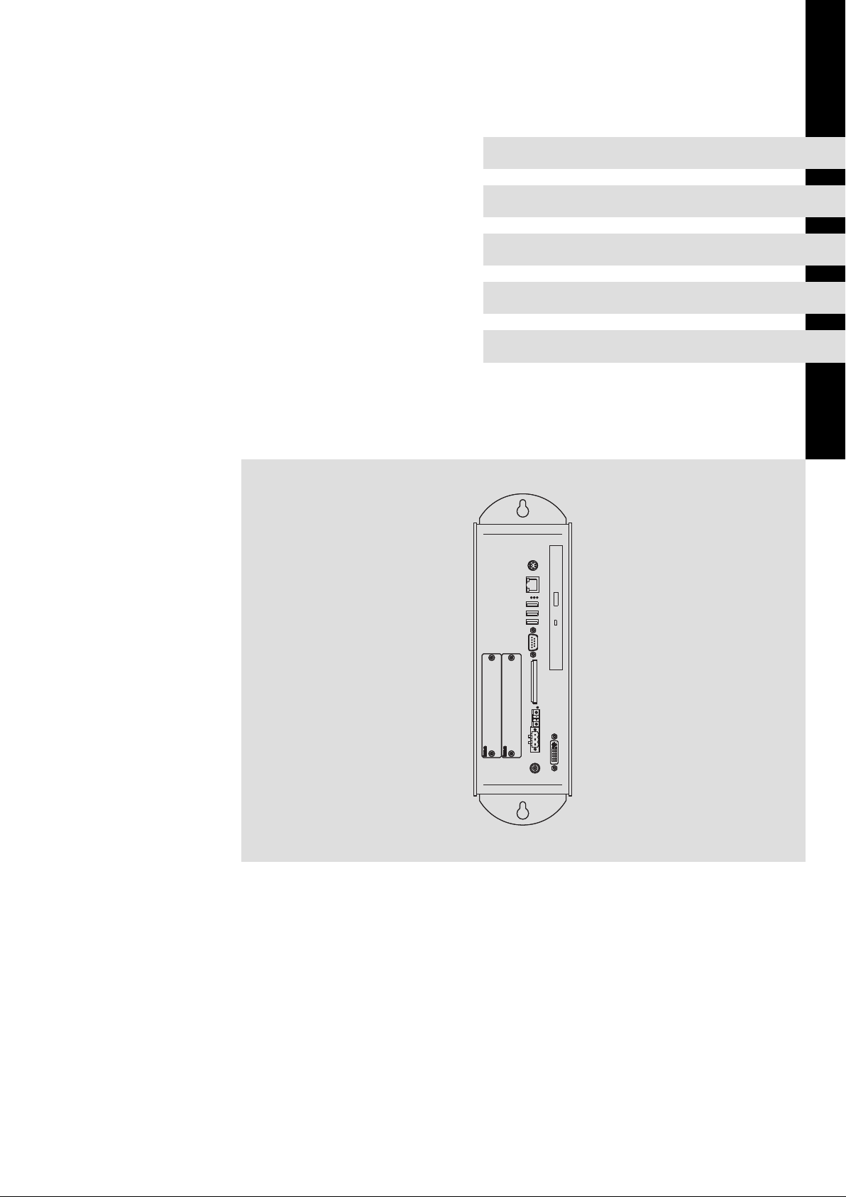
3.5 Controls and displays
0
1
2
3
0
4
5
6
7
8
9
:
;
CPC2700−001
Pos. Description
Control cabinet PC
DVD drive (optional)
PS/2
LAN (Ethernet)
Status LEDs
Error (red):
l Is lit if a power supply failure has occurred;
HD (yellow):
l Indicates access to a storage medium.
Power (green):
l Is lit when the supply voltage is present.
l Flashes (
l Is blinking (
l Is blinking (
UPS.
l Is blinking (
empty or missing).
l Blinks 4 x per second if the ACCU−PACK causes a short circuit or if the CAPS−PACK is completely
discharged.
USB
RS 232
CF Card
MC Card
ACU UPS
24 V DC
DVI
−
) in the case of a hardware error.
−−−−−−−
−−−−−
) when the ACU UPS (optional) is being charged.
−
−−−−−−
) when there is a supply voltage failure and the device is being supplied by the ACU
−−
−−−
) when the supply voltage of the ACU UPS is too low (e.g. rechargeable battery is
−
BA_CPCx8xx EN 3.0
19
Page 20

3
Product description
Options
ACU UPS control unit
3.6 Options
3.6.1 ACU UPS control unit
Description
The optional ACU UPS control unit in connection with a battery or capacitor pack adds a
UPS functionality to the Industrial PC of the EL 1800−9800, CS 5800−9800, CPC 2800, and
3241 C series.
The ACU UPS control unit is either pre−equipped by the factory or can be refitted by the
Lenze Service staff.
Features of the ACU UPS control unit
with battery pack (ACCU PACK) with capacitor pack (CAPS PACK)
l Bridges a short−term mains failure or mains
fluctuations and shuts down the PC.
l Software−based configuration
l Documentation for the battery pack
ACCU-Pack
l Data backup in the event of mains failure.
l Not suitable for Windows XP and Windows
Embedded Standard 2009.
l Software−based configuration
l Documentation for the capacitor pack
EPC50
ACU
0
S
3
Before
instruction
opening,
manual.
read
the
1
U
S
V
2
FAN3
FAN2
USB-µCON
CR2450
20
BLIGHT
T4A
F1
POWER
19
1
2
ACCU
RESET
4
CS57x0−042
2700 battery pack or 2701 capacitor pack (accessories)
Connection cable (included in delivery of battery pack/capacitor pack)
Port on industrial PC
ACU UPS control unit
Baseboard
20
BA_CPCx8xx EN 3.0
Page 21

3.7 Baseboard
Product description
Baseboard
3
HARDDISK / CD-ROM
POWER
FLAT-PANEL-LVDS
0
VGA
X3
X4
FAN0
1
5
FAN3
FAN2
2
CR2450
20
BLIGHT
USB-µCON
T4A
4
F1
POWER
Hard disk
CPU module
Battery ( 34)
ACU UPS control unit ( 20)
Fuse ( 35)
Socket connector for MC card
19
X1 X2
3
1
2
ACCU
RESET
CF-CARD
COM1
RT
USB_B
USB_C
GE
GN
USB_A
FAN1
MOUSE
x8xx_001
BA_CPCx8xx EN 3.0
21
Page 22

4
Technical data
General data and operating conditions
4 Technical data
4.1 General data and operating conditions
General data
Conformity and approval
Conformity
CE
Approbation
UL UL 508
Other
RoHS − Products lead−free in accordance with CE Directive
EN 61000−6−4
EN 61000−6−2
CSA C22.2
EMC Directive Class A, industrial premises
Programmable Controllers (File−No. E236341)
2011/65/EU
Protection of persons and equipment
Safety VDE0805 (EN60950),
Enclosure
Class of protection 3
EMC
Noise emission EN 61000−6−4
Noise immunity Zone B EN 61000−6−2
* Due to the high−energy single current pulses, a surge requires a suitable external connection with lightning
protection elements like for instance lightning conductors and overvoltage arresters.
VDE0870, UL
EN 60529
UL 508 (NEMA 250) Type 1 enclosure
IP20
Class A (industrial premises)
Industrial premises
EN 61000−4−2 ESD; severity: 3, i.e.
EN 61000−4−3 RF interference (housing)
EN 61000−4−4 Burst, severity: 3
EN 61000−4−5 Surge, severity 3 *
EN 61000−4−6 RF conducted
8 kV in the case of air discharge,
4 kV in the case of contact discharge
80 MHz 1000 MHz, 10 V/m 80 % AM (1 kHz)
150 kHz 80 MHz, 10 V/m 80 % AM (1 kHz)
22
BA_CPCx8xx EN 3.0
Page 23

Technical data
General data and operating conditions
Operating conditions
Mounting conditions
Place of installation
Mounting position Vertically with the ventilation slots at the top/bottom
Ambient conditions
Climatic
Storage
Transport −10 ... +60 °C
Operation Equipment−dependent ( 23)
Relative humidity 10 ... 90 %, no condensation
Site altitude
StoragetTransport < 12000 m amsl
Operation < 3000 m amsl
Control cabinet
−10 ... +60 °C
4
Note!
The failure probability of an electronic component increases with the ambient
temperature to which the component is subjected. Regarding the
serviceability and reliability, particular attention should be paid to the cooling
of the device. For every application, you should take care to keep the heating
of the device as low as possible.
ƒ We recommend to use forced−ventilated systems with "Smart Cool" fan
control to ensure sufficient heat dissipation.
The fan control monitors the internal temperature of the device and the
functioning of the fan. When a preset maximum temperature is exceeded,
the control system switches on the fan. When the fan speed falls below a
minimum speed, the control system signals a fault.
ƒ Systems with passive cooling via heatsinks should only be used if it is
guaranteed that there is always sufficient convection (e.g. by means of
external fan modules in the control cabinets or the installation of the device
in air−conditioned areas).
Permissible ambient temperatures for fanless systems
Standard device l With standard
Processor [°C]
Intelâ Atomä N270,
1.6 GHz
hard disk
5 ... 40 5 ... 45 0 ... 45 5 ... 40
l With hard disk for
continuous
operation (24/7)
1)
l With hard disk for
extended
temperature
range
l Up to 1 GB RAM
l With CF card
l With DVD writer
drive
BA_CPCx8xx EN 3.0
23
Page 24

4
Technical data
Electrical data
Permissible ambient temperatures for systems with "Smart Cool" cooling
Standard device l With standard
Processor [°C]
Intelâ Coreä Duo
1.66 GHz at max.
50 % CPU utilisation
2)
Intelâ Coreä Duo
1.66 GHz at max.
100 % CPU
utilisation
1) We recommend replacing the hard disk after 30,000 operating hours or after 5 years.
2) The CPU utilisation can be determined via the Windows task manager (register "System performance")
2)
hard disk
5 ... 45 5 ... 45 0 ... 45 5 ... 40
5 ... 40 5 ... 40 0 ... 40 5 ... 40
l With hard disk for
continuous
operation (24/7)
1)
l With hard disk for
extended
temperature
range
l Up to 1 GB RAM
l With CF card
l With DVD writer
drive
4.2 Electrical data
Standard device
Supply
CPC 2800 24 (+18 ... 30)
1) Without ACU UPS control unit, DVD−Drive, MC card, and USB consumer
2) With ACU UPS Control Unit DC +20 ... 30 V
ACU UPS control unit (option)
Type
ACU UPS 12 / 5 10 10 ... 600
1)
Subject to charging
Voltage Current at 24 V
Intelâ Core
Duoä
[V DC] [A] [A] [years]
2)
Operating voltage Max. current Charging current in operating
1.4 0.8 35 34 > 6 (25 °C)
[V DC] [mA] [mA]
1)
Intelâ Atomä Type Type Service life
At 5 V At 12 V
Fuse Buffer battery
range
1)
Approx. 250
24
BA_CPCx8xx EN 3.0
Page 25

4.3 Mechanical data
Versions and weights
Device housing Side cover Mass
CPC 2800 Powder−coated sheet steel Powder−coated aluminium 3.5
*)
Without optional accessories (hard disk, DVD drive, etc.)
Technical data
Mechanical data
4
*)
[kg]
280
178
All dimensions in millimetres.
340
9
21
101
30
310
40
CPC2700−003
BA_CPCx8xx EN 3.0
25
Page 26

5
Mechanical installation
Important notes
5 Mechanical installation
5.1 Important notes
The installation must be carried out by qualified, skilled personnel familiar with the
applicable national standards.
Proceed as follows for the mounting:
1. Check that the installation location meets the operating conditions specified in the
technical data.
2. Prepare the control cabinet mounting plate.
– Observe the dimensions and mounting clearances ( 25).
– There must be sufficient space for inserting disks into or ejecting them from the
DVD drive.
– The ventilation slots must not be covered.
3. Screw the device onto the mounting plate.
– The mounting location and the installation material must guarantee a permanent
mechanical connection.
5.2 Mounting steps
Proceed as follows for the mounting:
1. Check that the installation location meets the operating conditions specified in the
technical data ( 22).
2. Prepare the control cabinet mounting plate.
– Observe the dimensions and mounting clearances ( 25).
– There must be sufficient space for inserting disks into or ejecting them from the
DVD drive.
– The ventilation slots must not be covered.
3. Screw the device onto the mounting plate.
– The mounting location and the installation material must guarantee a permanent
mechanical connection.
26
BA_CPCx8xx EN 3.0
Page 27

6 Electrical installation
6.1 Important notes
The installation must be carried out by qualified, skilled personnel familiar with the
applicable national standards.
Stop!
Short circuit and static discharge
The device contains components which are endangered in the case of short
circuit or static discharge.
Possible consequences:
ƒ The device or parts of it will be destroyed.
Protective measures:
ƒ Always switch off the voltage supply when working on the device. This
particularly applies:
– Before connecting / disconnecting connectors.
– Before plugging in / plugging out modules.
ƒ All persons handling printed circuit boards have to take account of ESD
measures.
ƒ Contacts of plug connectors must not be touched.
ƒ Printed circuit boards may be touched only at places free from electrical
contacts and may be placed only on appropriate materials (e.g. on ESD
packaging or conductive foam material).
ƒ Printed circuit boards may only be transported and stored in ESD packaging.
Electrical installation
Important notes
6
BA_CPCx8xx EN 3.0
27
Page 28

6
Electrical installation
Wiring according to EMC
6.2 Wiring according to EMC
General notes l The electromagnetic compatibility of the system depends on the type and accuracy of the
installation. Please especially note the following:
– Structure
– Shielding
– Earthing
l In the case of a differing installation it is required for evaluating the conformity to the EMC
Directive to check the system with regard to compliance with the EMC limit values. This for
instance applies to:
– The use of unshielded cables
l The end user is responsible for compliance with the EMC Directive.
– If you observe the following measures, you can be sure that no EMC problems will occur
during operation and that the EMC Directive or the EMC law is met.
– If devices which do not meet the CE requirement with regard to noise immunity
EN 61000−4−2 are actuated near the system, these devices can be affected
electromagnetically by the system.
Structure l Connect device to the earthed mounting plate:
– Mounting plates with an electroconductive surface (zinc−coated or stainless steel) allow for
continuous contacting.
– Coated plates are not suitable for an EMC−compliant installation.
l If you use several mounting plates:
– Connect mounting plates to each other on a large surface and in a conductive manner (e.g.
by means of copper strips).
l When installing the cables, observe a spatial separation of signal and mains cables.
l Route the cables as near to the reference potential as possible. Freely suspended cables act
like aerials.
Shielding l Preferably only use cables with a braid.
l The coverage of the shield should be more than 80%.
l In the case of data lines for a serial coupling, always use metallic or metallised plugs. Connect
the shield of the data line on the connector shell.
Earthing l Earth all metallically conductive components by the use of corresponding cables from a
central earthing point (PE rail).
l Comply with the minimum cross−sections defined in the safety instructions:
– With regard to EMC, however, not the cable cross−section, but the surface of the cable and
of the extensive contacting is decisive.
28
BA_CPCx8xx EN 3.0
Page 29

Connecting the supply and peripheral devices
6.3 Connecting the supply and peripheral devices
6.3.1 Terminal diagram supply
L1
N
PE
0
0VUSV
PE +24 V
+
23
Electrical installation
Terminal diagram supply
S
F
N
L1
+
~=
1
+
+24
0V
6
IPC
Power supply unit
Battery pack (Option)
Capacitor pack (Option)
Note!
ƒ Observe the max. permissible input voltage.
Professionally fuse the device on the input side against voltage fluctuations
and voltage peaks.
ƒ The IPC boots up as soon as the supply voltage is applied.
After the operating system has been shut down, the IPC switches off
automatically. For restarting, the supply voltage has to be disconnected for a
short time.
6.3.2 24 V connection (X101)
Description Connection type Cable type
0V U
DC 24 V connection
IPC001
3−pole Phoenix Combicon
socket
Elx7xx−006
Cable (conductor
cross−section max. 2.5 mm
with Phoenix Combicon plug,
MSTB 2.5 / 3−STF−5.08
2
)
BA_CPCx8xx EN 3.0
PE connection M4 Recessed head screw
IPC001
Separate earthing conductor
(min. 2.5 mm
2
) with ring
cable lug
29
Page 30

6
Electrical installation
Connecting the supply and peripheral devices
UPS−PACK connection (X102)
6.3.3 UPS−PACK connection (X102)
Description Connection type Cable type
Terminal for Battery pack /
Capacitor pack
IPC001
6.3.4 Monitor interface (X109)
Description Connection type Cable type
Monitor connection with DVI
interface or with VGA
interface and adapter
IPC001
2−pin socket
DVI−I socket
In the scope of supply of the
pack; length 2.5 m; extension
available
DVI−I single link (18+5)
DVI−I double link (24+5)
DVI−D single link (18+1)
DVI−D double link (24+1)
DVI−A no link (12+5)
VGA cable with DVI−I
plug−to−VGA socket adapter
6.3.5 PS/2 interface (X108)
IPC001
6.3.6 Serial interface (X103)
1
6
IPC001
Description Connection type Cable type
PS/2 mouse
PS/2 connection 6−pin, mini DIN
Description Connection type Cable type
RS232 connection
Pin 1: DCD
Pin 2: RxD
Pin 3: TxD
Pin 4: DTR
Pin 5: GND
Pin 6: DSR
Pin 7: RTS
Pin 8: CTS
Pin 9: RI
9−pin Sub−D plug
(a keyboard and a mouse can
be connected via a PS/2 Y
cable)
Control cable, shielded, with
9−pin Sub−D socket
30
BA_CPCx8xx EN 3.0
Page 31

6.3.7 Ethernet interface (X107)
Description Connection type Cable type
Ethernet connection
10/100 Mbps
Green LED (SPEED):
on = 100 MBPS
off = 10 Mbps
Yellow LED (LINK/ACTIVITY):
on or blinking = LINK
/ACTIVITY
off = no LINK
IPC001
Note!
If the RJ45 plug connection is exposed to oscillating or vibrating stress:
ƒ Use a strain relief in the immediate vicinity of the RJ45 socket.
ƒ Select the contact surface on which the device is mounted as fixing point of
the strain relief.
ƒ Comply with the related minimum bending radius of the cable used.
Electrical installation
Connecting the supply and peripheral devices
Ethernet interface (X107)
Network cable CAT5 S/UTP or
RJ45 socket
CAT5e S/FTP (recommended),
cable length: max. 100 m
6
6.3.8 USB interface (X104, X105, X106)
Description Connection type Cable type
USB 2.0 host connection
Max. load: 5 V/500 mA
IPC001
6.3.9 Communication interface (MC card)
Description Connection type Cable type
Interface for MC card Socket connector −
EL100−013
USB−A socket USB cable with USB−A plug
BA_CPCx8xx EN 3.0
31
Page 32

7
Maintenance
Regular checks
7 Maintenance
Stop!
Short circuit and static discharge
The device contains components which are endangered in the case of short
circuit or static discharge.
Possible consequences:
ƒ The device or parts of it will be destroyed.
Protective measures:
ƒ Always switch off the voltage supply when working on the device. This
particularly applies:
– Before connecting / disconnecting connectors.
– Before plugging in / plugging out modules.
ƒ All persons handling printed circuit boards have to take account of ESD
measures.
ƒ Contacts of plug connectors must not be touched.
ƒ Printed circuit boards may be touched only at places free from electrical
contacts and may be placed only on appropriate materials (e.g. on ESD
packaging or conductive foam material).
ƒ Printed circuit boards may only be transported and stored in ESD packaging.
7.1 Regular checks
The device is free of maintenance. Nevertheless, visual inspections should be carried out
at regular intervals which must not be too long, depending on the ambient conditions.
Please check the following:
ƒ Does the environment of the device meet the operating conditions specified in the
Technical data?
ƒ Is the heat dissipation of the device not impeded by dust or dirt?
ƒ Are the mechanical and electrical connections o.k.?
32
BA_CPCx8xx EN 3.0
Page 33

7.2 Cleaning
Stop!
ƒ Before cleaning, disconnect the device from the power supply.
Maintenance
Cleaning
Sensitive surfaces and components
The device can be damaged if it is not appropriately cleaned.
Possible consequences:
ƒ The housing gets scratched or dull if you use alcoholic, solvent−containing or
scouring cleaning agents.
ƒ Electrical components can be damaged ...
– by a short circuit caused by humidity.
– by static discharge.
Protective measures:
ƒ Observe the following notes.
7
ƒ Clean the device with a clean, lint−free and soft cloth. Do not use liquid or foaming
detergent since it may enter the housing or terminals.
BA_CPCx8xx EN 3.0
33
Page 34

7
7.3 Repair
7.3.1 Remove the PC housing
Maintenance
Repair
Remove the PC housing
0
1
0
1. Remove the mains cable ( 29).
2. Loosen the four screws on the left side of the housing.
cpc2700−005
3. Remove the cover .
7.3.2 Mount the PC housing
1. Place the cover on the left side of the housing.
2. Attach the cover with the four screws .
7.3.3 Battery change
3. Plug on the mains cable ( 29).
Danger!
Danger of fire and explosion
On the baseboard there is a battery for buffering the clock (RTC) when the
device has been switched off.
Possible consequences:
ƒ The use of other batteries than the approved ones or improper handling can
result in a fire, explosion, or environmental damage.
Protective measures:
ƒ The battery may only be replaced by an approved battery type according to
the following list.
ƒ The battery may not be recharged or opened. Furthermore it may not be
thrown into a fire or be heated above 100 °C (212 °F).
34
Approved types:
ƒ Matsushita CR2450, Renata CR2450N, Sony Corp. CR2450B, Toshiba CR2450, Varta
CR2450
BA_CPCx8xx EN 3.0
Page 35

Maintenance
Repair
Fuse change
FAN3
M
C-
CAN2
CA
N2
CAN1
How to proceed:
1. Remove the MC Card, if inserted.
2. Remove the old battery from the support.
3. Insert a new approved battery into the support so that the positive pole is at the
top.
FAN2
BLIGHT
USB-µCON
T4A
F1
POWER
+
CR2450
0
20
19
1
2
ACCU
RESET
CF-CARD
ELx7xx−017
7
According to European legislation you are obliged to dispose of batteries separately, using
the take−back systems specified.
7.3.4 Fuse change
Stop!
Damage of the device by non−permissible fuse possible
The baseboard in the device is protected by a fuse which will be damaged if
the supply voltage applied is too high.
Possible consequences:
ƒ The device can be damaged if a non−approved fuse is installed.
Protective measures:
ƒ The fuse may only be replaced by an approved type.
Approved types:
ƒ Littelfuse 0454 004
BA_CPCx8xx EN 3.0
35
Page 36

7
Maintenance
Repair
Fuse change
FAN3
M
C-
CAN
2
CAN2
CAN1
FAN2
CR2450
20
BLIGHT
0
USB-µCON
T4A
F1
POWER
19
1
2
ACCU
RESET
CF-CARD
ELx7xx−018
How to proceed:
1. Remove the MC Card, if inserted.
2. Remove the old fuse from the support.
3. Insert a new approved fuse into the support.
36
BA_CPCx8xx EN 3.0
Page 37

8 Index
A
ACU UPS control unit, 20
Ambient conditions
− Climatic, 23
− Site altitude, 23
Application as directed, 15
Approbation, 22
B
Back−up battery, change, 34
Baseboard, 21
Battery, change, 34
Battery pack, 20
C
Capacitor pack, 20
Class of protection, 22
Cleaning, 33
COM connection, 30
Conformity, 22
Controls, 19
D
Danger
− Short circuit, 27, 32
− Static discharge, 27, 32
Definition of notes used, 7
Device
− overview, 19
− radio interference, 11
− version, 25
− weight, 25
Displays, 19
Disposal, 10
DVI port, 30
E
Electrical data, 24
Electrical installation, 27
− COM, 30
− EMC−compliant wiring, 28
− Ethernet, 31
− LAN, 31
− Mains, 29
− MC card, 31
− Monitor, 30
− PS/2, 30
− RS232, 30
− Terminal diagram, 29
− UPS, 30
− USB, internal, 31
EMC, 22
− earthing, 28
− shielding, 28
− structure, 28
EMC−compliant wiring, 28
Enclosure, 22
Error behaviour, 11
Ethernet connection, 31
F
Fault, behaviour, 11
Fuse, change, 35
G
General data, 22
I
Identification, 17
Installation, CE−typical drive
system
− earthing, 28
− shielding, 28
− structure, 28
Installation, electrical, 27
Installation, mechanical, 26
L
LAN connection, 31
Index 8
M
Mains connection, 29
Maintenance, 32
− Back−up battery, 34
− Cleaning, 33
− Fuse, 35
− Mount the PC housing, 34
− Regular checks, 32
− Remove the PC housing, 34
− Repair, 34
MC card, 31
Mechanical data, 25
− version, device, 25
− weight, device, 25
Mechanical installation, 26
Monitor port, 30
Mounting conditions
− Mounting position, 23
− Place of installation, 23
N
Nameplate, 17
Nameplate data, 17
Noise emission, 22
Noise immunity, 22
Notes, definition, 7
O
Operating conditions, 23
− Mounting conditions, mounting
position, 23
− mounting conditions, Place of
installation, 23
Overview, 19
P
PC housing
− Mount, 34
− Remove, 34
Product description, 14
− application as directed, 15
PS/2 connection, 30
BA_CPCx8xx EN 3.0
37
Page 38

Index8
R
Radio interference, 11
Regular checks, 32
Repair, 34
RS232 connection, 30
S
Safety, 22
Safety instructions, 8
− application as directed, 15
− definition, 7
− layout, 7
Scope of supply, 14
Shielding, EMC, 28
Short circuit, 27, 32
Site altitude, 23
Static discharge, 27, 32
Supply, 24
T
Technical data, 22
− Electrical data, 24
− General data, 22
− mechanical data, 25
− Operating conditions, 23
Temperatures, 23
Terminal diagram, 29
Type code, 17
− finding, 17
U
UPS, 20
UPS connection, 30
USB connection, internal, 31
V
Validity, documentation, 5
Version, device, 25
Voltage supply, 24
W
Weight, device, 25
38
BA_CPCx8xx EN 3.0
Page 39

F
(
Ê
ü
© 01/2014
Lenze Automation GmbH
Postfach 10 13 52, D−31763 Hameln
Hans−Lenze−Str. 1, D−31855 Aerzen
Germany
+495154 82−0
+495154 82−2800
lenze@lenze.com
www.lenze.com
Service Lenze Service GmbH
Breslauer Straße 3, D−32699 Extertal
Germany
(
Ê
0080002446877 (24 h helpline)
+49515482−1112
service@lenze.com
BA_CPCx8xx § .ND; § EN § 3.0 § TD06
10987654321
 Loading...