

Page 1
MA_CPCx8xx
.ND<
L−force Controls
Montageanleitung
Mounting Instructions
Instructions de montage
Ä.ND<ä
Instrucciones para el montaje
Istruzioni per il montaggio
Industrial PC
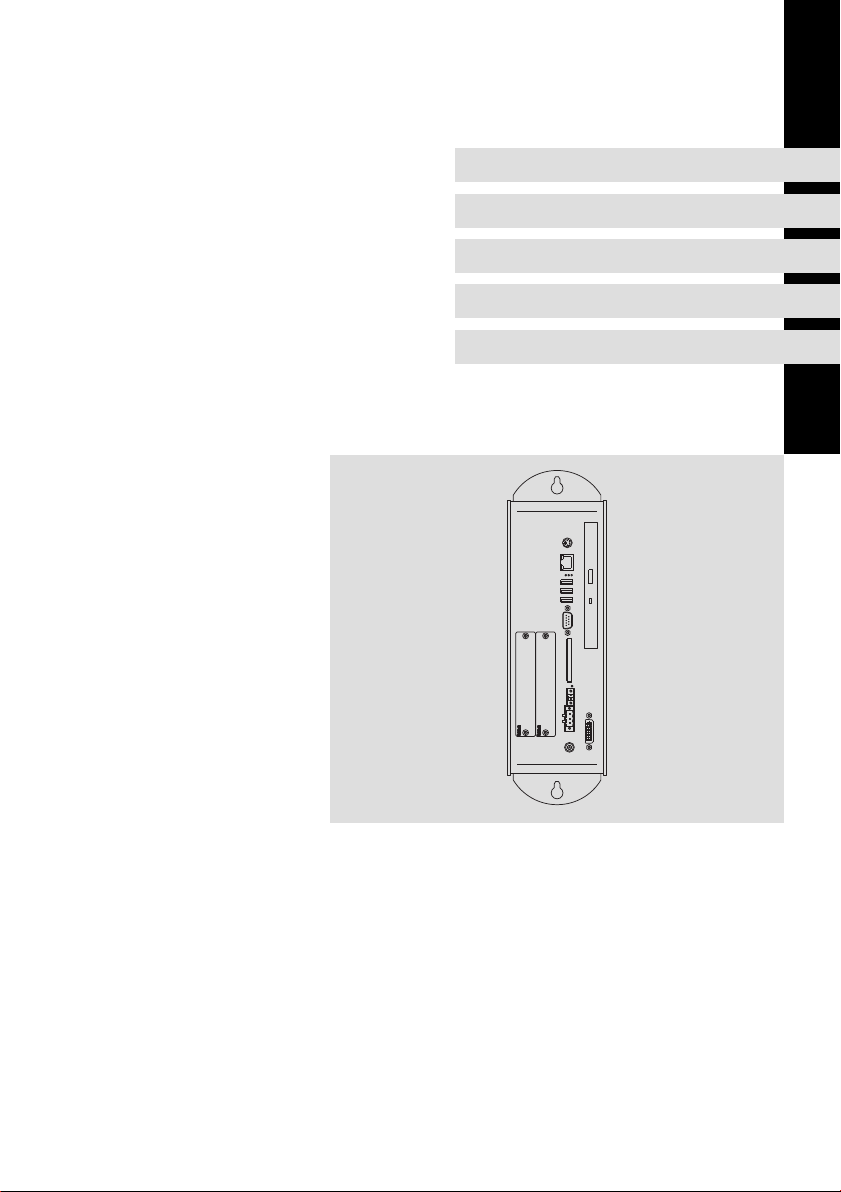
CPC 2800
Control Cabinet PC (CPC)
Page 2

Lesen Sie zuerst diese Anleitung, bevor Sie mit den Arbeiten beginnen!
Beachten Sie die enthaltenen Sicherheitshinweise.
Ausführliche Informationen finden Sie in der Betriebsanleitung.
Read these instructions before you start working!
Follow the safety instructions given.
More detailed information can be found in the Operating Instructions.
Veuillez lire attentivement cette documentation avant toute action !
Les consignes de sécurité doivent impérativement être respectées.
Pour plus de détails, consulter les instructions de mise en service.
Lea estas instrucciones antes de empezar a trabajar.
Observe las instrucciones de seguridad indicadas.
El manual de instrucciones implica informaciónes detalladas.
Prima di iniziare qualsiasi intervento, leggere le presenti istruzioni.
Osservare le note di sicurezza.
Le istruzioni operative contengono informazioni dettagliati.
Page 3

Inhalt i
1 Über diese Dokumentation 4. . . . . . . . . . . . . . . . . . . . . . . . . . . . . . . . . . . . . . . . .
1.1 Verwendete Hinweise 4. . . . . . . . . . . . . . . . . . . . . . . . . . . . . . . . . . . . . . .
2 Sicherheitshinweise 5. . . . . . . . . . . . . . . . . . . . . . . . . . . . . . . . . . . . . . . . . . . . . . .
2.1 Allgemeine Sicherheitshinweise 5. . . . . . . . . . . . . . . . . . . . . . . . . . . . . .
2.2 Sicherheitshinweise für die Installation nach UL 6. . . . . . . . . . . . . . . . .
3 Produktbeschreibung 8. . . . . . . . . . . . . . . . . . . . . . . . . . . . . . . . . . . . . . . . . . . . .
3.1 Lieferumfang 8. . . . . . . . . . . . . . . . . . . . . . . . . . . . . . . . . . . . . . . . . . . . . .
3.2 Bedien− und Anzeigeelemente 9. . . . . . . . . . . . . . . . . . . . . . . . . . . . . . . .
4 Installation 11. . . . . . . . . . . . . . . . . . . . . . . . . . . . . . . . . . . . . . . . . . . . . . . . . . . . . .
4.1 Wichtige Hinweise 11. . . . . . . . . . . . . . . . . . . . . . . . . . . . . . . . . . . . . . . . . .
4.2 Abmessungen 12. . . . . . . . . . . . . . . . . . . . . . . . . . . . . . . . . . . . . . . . . . . . . .
4.3 Montageschritte 12. . . . . . . . . . . . . . . . . . . . . . . . . . . . . . . . . . . . . . . . . . .
4.4 Elektrische Installation 13. . . . . . . . . . . . . . . . . . . . . . . . . . . . . . . . . . . . . .
MA_CPCx8xx DE/EN/FR/ES/IT 2.0
3
Page 4
1
Über diese Dokumentation
Verwendete Hinweise
1 Über diese Dokumentation
0Abb. 0Tab. 0
1.1 Verwendete Hinweise
Um auf Gefahren und wichtige Informationen hinzuweisen, werden in dieser
Dokumentation folgende Piktogramme und Signalwörter verwendet:
Sicherheitshinweise
Aufbau der Sicherheitshinweise:
Gefahr!
(kennzeichnet die Art und die Schwere der Gefahr)
Hinweistext
(beschreibt die Gefahr und gibt Hinweise, wie sie vermieden werden
kann)
Piktogramm und Signalwort Bedeutung
Gefahr!
Gefahr!
Stop!
Anwendungshinweise
Gefahr von Personenschäden durch gefährliche elektrische Spannung
Hinweis auf eine unmittelbar drohende Gefahr, die den
Tod oder schwere Verletzungen zur Folge haben kann,
wenn nicht die entsprechenden Maßnahmen getroffen
werden.
Gefahr von Personenschäden durch eine allgemeine
Gefahrenquelle
Hinweis auf eine unmittelbar drohende Gefahr, die den
Tod oder schwere Verletzungen zur Folge haben kann,
wenn nicht die entsprechenden Maßnahmen getroffen
werden.
Gefahr von Sachschäden
Hinweis auf eine mögliche Gefahr, die Sachschäden zur
Folge haben kann, wenn nicht die entsprechenden Maßnahmen getroffen werden.
Piktogramm und Signalwort Bedeutung
Hinweis!
Tipp!
4
Wichtiger Hinweis für die störungsfreie Funktion
Nützlicher Tipp für die einfache Handhabung
Verweis auf andere Dokumentation
MA_CPCx8xx DE/EN/FR/ES/IT 2.0
Page 5

2 Sicherheitshinweise
2.1 Allgemeine Sicherheitshinweise
Auch zu Ihrer eigenen Sicherheit
Gefahr!
Wenn Sie die folgenden grundlegenden Sicherheitsmaßnahmen
missachten, kann dies zu schweren Personenschäden und
Sachschäden führen:
ƒ Lenze−Antriebs− und Automatisierungskomponenten ...
... ausschließlich bestimmungsgemäß verwenden.
... niemals trotz erkennbarer Schäden in Betrieb nehmen.
... niemals technisch verändern.
... niemals unvollständig montiert in Betrieb nehmen.
... niemals ohne erforderliche Abdeckungen betreiben.
... können während und nach dem Betrieb − ihrer Schutzart entsprechend −
spannungsführende, auch bewegliche oder rotierende Teile haben. Oberflächen können heiß sein.
ƒ Für Lenze−Antriebs− und Automatisierungskomponenten ...
... nur das zugelassene Zubehör verwenden.
... nur Original−Ersatzteile des Herstellers verwenden.
ƒ Alle Vorgaben der beiliegenden und zugehörigen Dokumentation
beachten.
Dies ist Voraussetzung für einen sicheren und störungsfreien Betrieb sowie
für das Erreichen der angegebenen Produkteigenschaften.
Die in diesem Dokument dargestellten verfahrenstechnischen Hinweise
und Schaltungsausschnitte sind Vorschläge, deren Übertragbarkeit auf die
jeweilige Anwendung überprüft werden muss. Für die Eignung der angegebenen Verfahren und Schaltungsvorschläge übernimmt der Hersteller keine
Gewähr.
ƒ Alle Arbeiten mit und an Lenze−Antriebs− und
Automatisierungskomponenten darf nur qualifiziertes Fachpersonal
ausführen.
Nach IEC 60364 bzw. CENELEC HD 384 sind dies Personen, ...
... die mit Aufstellung, Montage, Inbetriebsetzung und Betrieb des Produkts
vertraut sind.
... die über die entsprechenden Qualifikationen für ihre Tätigkeit verfügen.
... die alle am Einsatzort geltenden Unfallverhütungsvorschriften, Richtli-
nien und Gesetze kennen und anwenden können.
Sicherheitshinweise
Allgemeine Sicherheitshinweise
2
MA_CPCx8xx DE/EN/FR/ES/IT 2.0
5
Page 6

2
Sicherheitshinweise
Sicherheitshinweise für die Installation nach UL
2.2 Sicherheitshinweise für die Installation nach UL
Original − Englisch
Approval
Underwriter Laboratories (UL), UL508 and CSA C22.2 No. 142−M1987, (UL File
Number E236341)
Ratings
ƒ Input 18 ... 30 V DC , max. 4 A
ƒ ACCU−Pack and CAPS−Pack: max 0.6 A
ƒ Max. ambient temperature 50 °C.
ƒ Optional communication ratings:
– RS232−Connection: max. 3 A
– USB−Connection: max. 1 A
– PS/2−Connection: max. 1 A
– LAN−Connection: Standard ISDN or RJ45
– DVI−Connection: max. 1 A
Warnings!
Field Wiring Markings
Wiring Terminal MSTB 2,5/3−STF−5,08:
ƒ Use copper wire only.
ƒ AWG 18 ... AWG 12 (0.82 mm
ƒ Torque 5...7 lb−in (0.5 ... 0.6 Nm)
Battery
ƒ Replace battery with any from the list below, Part No. CR 2450
only. Use of another battery may present a risk of fire or
explosion.
Recommended CR2450 (R/C, BBVC2) types:
Renata Part.no. CR2450N, Sony Corp. part no. CR2450B, Toshiba
part no. CR2450, Varta part no. CR2450, Matsushita part no.
CR2450
ƒ Battery may explode if mistreated. Do not recharge, disassemble,
dispose of in fire or heat above 100 °C (212 °F).
ƒ Dispose of used battery according to the regulation of recycling
or waste.
2
... 3.3 mm2)
6
MA_CPCx8xx DE/EN/FR/ES/IT 2.0
Page 7

Sicherheitshinweise
Sicherheitshinweise für die Installation nach UL
Original − Französisch
Homologation
Underwriter Laboratories (UL), UL508 et CSA C22.2 n° 142−M1987, (n° de dossier
UL E236341)
Caractéristiques assignées
ƒ Alimentation 18 ... 30 V CC , 4 A max.
ƒ Pack ACCU et CAPS : maximum 0,6 A
ƒ Température ambiante maximale : 50 °C.
ƒ Caractéristiques de communication assignées (option) :
– Port RS232 : maximum 3 A
– Port USB : maximum 1 A
– Port PS/2 : maximum 1 A
– Port LAN : RNIS standard ou RJ45
– Port DVI : maximum 1 A
Warnings!
Marquage du câblage à pied d’oeuvre
Bornier de câblage MSTB 2,5/3−STF−5,08 :
ƒ Utiliser exclusivement des conducteurs en cuivre.
ƒ AWG 18 ... AWG 12 (0.82 mm
ƒ Couple de 5 à 7 lb−in (0,5 ... 0,6 Nm)
Batterie
ƒ Remplacer la batterie par l’un des types répertoriés dans la liste
ci−dessous, n° de référence CR 2450 uniquement. L’utilisation
d’une autre batterie présente un risque d’incendie ou
d’explosion.
Types CR2450 recommandés (R/C, BBVC2) :
Renata référence CR2450N, Sony Corp. référence CR2450B,
Toshiba référence CR2450, Varta référence CR2450, Matsushita
référence CR2450
ƒ Toute utilisation non conforme de la batterie entraîne un risque
d’explosion. Ne pas recharger, démonter, jeter au feu ni exposer
la batterie à une chaleur supérieure à 100 °C (212 °F).
ƒ Eliminer la batterie conformément à la réglementation en
vigueur en matière de recyclage ou de traitement des déchets.
2
... 3.3 mm2)
2
MA_CPCx8xx DE/EN/FR/ES/IT 2.0
7
Page 8

3
Produktbeschreibung
Lieferumfang
3 Produktbeschreibung
3.1 Lieferumfang
Anzahl Bezeichnung
1 Schaltschrank−PC
1 Anschlussstecker für Spannungsversorgung
1 DVD "PC based Automation"
1 Testbericht
1 Gerätepass
8
MA_CPCx8xx DE/EN/FR/ES/IT 2.0
Page 9
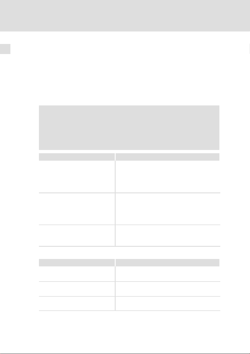
3.2 Bedien− und Anzeigeelemente
0
Produktbeschreibung
Bedien− und Anzeigeelemente
0
3
1
2
3
4
5
6
7
8
9
:
;
Pos. Beschreibung
Schaltschrank−PC
DVD−Laufwerk (Option)
PS/2
LAN (Ethernet)
MA_CPCx8xx DE/EN/FR/ES/IT 2.0
CPC2700−001
9
Page 10

3
Produktbeschreibung
Bedien− und Anzeigeelemente
BeschreibungPos.
Status−LEDs
Error (rot):
l Leuchtet, wenn ein Fehler in der Stromversorgung vorliegt;
HD (gelb):
l Zeigt den Zugriff auf ein Speichermedien an.
Power (grün):
l Leuchtet, wenn die Versorgungsspannung vorhanden ist.
l Blitzt (
l Blinkt (
l Blinkt (
ACU USV versorgt wird.
l Blinkt (
leer oder fehlt).
l Blinkt 4 x pro Sekunde, wenn das ACCU−PACK einen Kurzschluss verursacht oder das
CAPS−PACK völlig entleert ist.
USB
RS 232
CF−Card
MC−Card
ACU USV
24 V DC
DVI
−
), wenn ein Hardwarefehler vorliegt.
−−−−−−−
−−−−−
), wenn die ACU USV (Option) lädt.
−
−−−−−−
), wenn die Versorgungsspannung ausgefallen ist und das Gerät von der
−−
−−−
), bei einer zu niedrigen Versorgungsspannung durch die ACU USV (z. B. Akku
−
10
MA_CPCx8xx DE/EN/FR/ES/IT 2.0
Page 11

4 Installation
4.1 Wichtige Hinweise
ƒ Damit eine ausreichende Wärmeabfuhr gewährleistet ist, darf das Gerät
nur senkrecht, mit den Belüftungsöffnungen oben und unten, an eine
Schaltschrankwand geschraubt werden.
ƒ Bei der lüfterlosen Variante muss die rückseitige Gehäuseplatte plan auf
der Schaltschrankwand aufliegen, um darüber zusätzlich Wärme
abzuführen. Die rückseitige Gehäuseplatte kann eine
Oberflächentemperatur von bis zu 65 °C erreichen.
Stop!
Kurzschluss und statische Entladungen
Das Gerät enthält Bauelemente, die bei Kurzschluss oder statischer
Entladung gefährdet sind.
Mögliche Folgen:
ƒ Das Gerät oder Teile davon werden zerstört.
Schutzmaßnahmen:
ƒ Bei allen Arbeiten am Gerät, immer Spannungsversorgung
abschalten. Dies gilt insbesondere:
– vor dem Anschließen / Abziehen von Steckverbindern.
– vor dem Stecken / Ziehen von Modulen.
ƒ Alle Personen, die Flachbaugruppen handhaben, müssen
ESD−Maßnahmen berücksichtigen.
ƒ Kontakte von Steckverbindern dürfen nicht berührt werden.
ƒ Flachbaugruppen dürfen nur an kontaktfreien Stellen angefasst
werden und nur auf geeigneten Unterlagen abgelegt werden
(z. B. auf ESD−Verpackung oder leitfähigem Schaumstoff).
ƒ Flachbaugruppen dürfen nur in ESD−Verpackungen transportiert
und gelagert werden.
Installation
Wichtige Hinweise
4
MA_CPCx8xx DE/EN/FR/ES/IT 2.0
11
Page 12
4
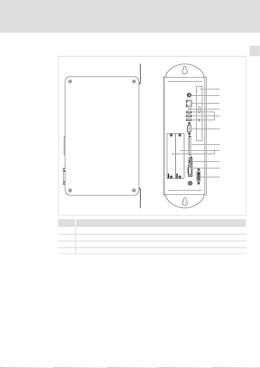
4.2 Abmessungen
Installation
Abmessungen
280
Alle Maße in Millimeter.
4.3 Montageschritte
So gehen Sie bei der Montage vor:
1. Kontrollieren, dass der Einbauort die in den Technischen Daten
genannten Einsatzbedingungen gewährleistet.
2. Schaltschrank−Montageplatte vorbereiten.
– Abmessungen und Einbaufreiräume beachten ( 12).
– Zum Laden/Entladen des DVD−Laufwerks muss ausreichend Platz
vorhanden sein.
– Die Belüftungsöffnungen dürfen nicht abgedeckt sein.
3. Gerät an der Montageplatte festschrauben.
– Der Montageort und das Montagematerial muss die mechanischen
Verbindungen dauerhaft gewährleisten.
178
340
9
21
101
30
310
40
CPC2700−003
12
MA_CPCx8xx DE/EN/FR/ES/IT 2.0
Page 13
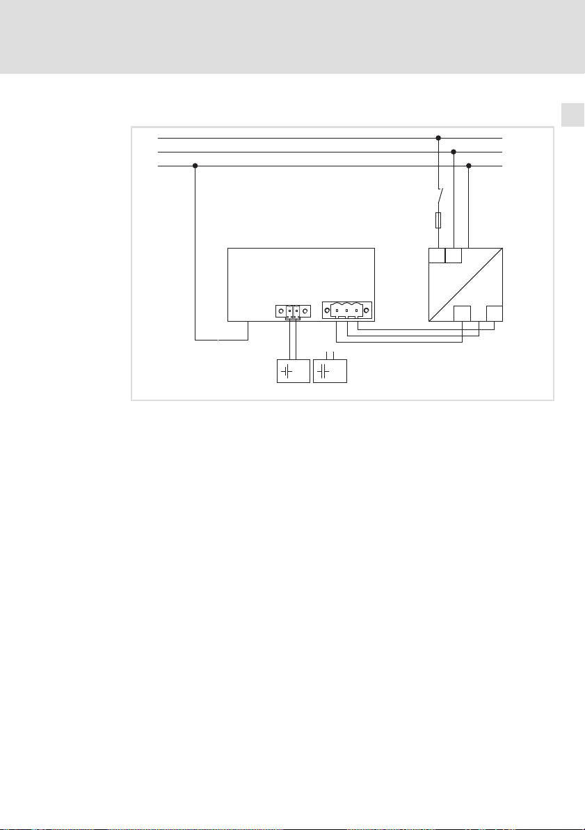
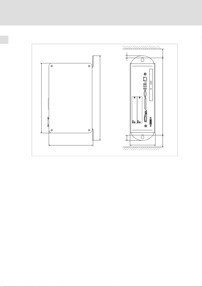
4.4 Elektrische Installation
L1
N
PE
0
+
0VUSV
PE +24 V
23
Installation
Elektrische Installation
S
F
N
L1
+
~=
1
+
0V
4
+24
IPC
Netzteil
Batteriepack (Option)
Kondensatorpack (Option)
MA_CPCx8xx DE/EN/FR/ES/IT 2.0
Elx7xx−006
13
Page 14

Contentsi
1 About this documentation 15. . . . . . . . . . . . . . . . . . . . . . . . . . . . . . . . . . . . . . . . . .
1.1 Notes used 15. . . . . . . . . . . . . . . . . . . . . . . . . . . . . . . . . . . . . . . . . . . . . . . .
2 Safety instructions 16. . . . . . . . . . . . . . . . . . . . . . . . . . . . . . . . . . . . . . . . . . . . . . . .
2.1 General safety information 16. . . . . . . . . . . . . . . . . . . . . . . . . . . . . . . . . . .
2.2 Safety instructions for the installation according to UL 17. . . . . . . . . . . .
3 Product description 19. . . . . . . . . . . . . . . . . . . . . . . . . . . . . . . . . . . . . . . . . . . . . . .
3.1 Scope of supply 19. . . . . . . . . . . . . . . . . . . . . . . . . . . . . . . . . . . . . . . . . . . .
3.2 Controls and displays 20. . . . . . . . . . . . . . . . . . . . . . . . . . . . . . . . . . . . . . . .
4 Installation 22. . . . . . . . . . . . . . . . . . . . . . . . . . . . . . . . . . . . . . . . . . . . . . . . . . . . . .
4.1 Important notes 22. . . . . . . . . . . . . . . . . . . . . . . . . . . . . . . . . . . . . . . . . . . .
4.2 Dimensions 23. . . . . . . . . . . . . . . . . . . . . . . . . . . . . . . . . . . . . . . . . . . . . . . .
4.3 Mounting steps 23. . . . . . . . . . . . . . . . . . . . . . . . . . . . . . . . . . . . . . . . . . . .
4.4 Electrical installation 24. . . . . . . . . . . . . . . . . . . . . . . . . . . . . . . . . . . . . . . .
14
MA_CPCx8xx DE/EN/FR/ES/IT 2.0
Page 15
About this documentation
Notes used
1
1 About this documentation
0Fig. 0Tab. 0
1.1 Notes used
The following pictographs and signal words are used in this documentation to
indicate dangers and important information:
Safety instructions
Structure of safety instructions:
Danger!
(characterises the type and severity of danger)
Note
(describes the danger and gives information about how to prevent
dangerous situations)
Pictograph and signal word Meaning
Danger!
Danger!
Stop!
Application notes
Danger of personal injury through dangerous electrical
voltage.
Reference to an imminent danger that may result in
death or serious personal injury if the corresponding
measures are not taken.
Danger of personal injury through a general source of
danger.
Reference to an imminent danger that may result in
death or serious personal injury if the corresponding
measures are not taken.
Danger of property damage.
Reference to a possible danger that may result in
property damage if the corresponding measures are not
taken.
Pictograph and signal word Meaning
Note!
Tip!
MA_CPCx8xx DE/EN/FR/ES/IT 2.0
Important note to ensure troublefree operation
Useful tip for simple handling
Reference to another documentation
15
Page 16

2
Safety instructions
General safety information
2 Safety instructions
2.1 General safety information
For your own safety
Danger!
Disregarding the following basic safety measures may lead to
severe personal injury and damage to material assets!
ƒ Lenze drive and automation components ...
... must only be used for the intended purpose.
... must never be operated if damaged.
... must never be subjected to technical modifications.
... must never be operated unless completely assembled.
... must never be operated without the covers/guards.
... can − depending on their degree of protection − have live, movable or
rotating parts during or after operation. Surfaces can be hot.
ƒ For Lenze drive and automation components ...
... only use approved accessories.
... only use original manufacturer spare parts.
ƒ All specifications of the corresponding enclosed documentation must be
observed.
This is vital for a safe and trouble−free operation and for achieving the
specified product features.
The procedural notes and circuit details provided in this document are
proposals which the user must check for suitability for his application. The
manufacturer does not accept any liability for the suitability of the specified
procedures and circuit proposals.
ƒ Only qualified skilled personnel are permitted to work with or on Lenze
drive and automation components.
According to IEC 60364 or CENELEC HD 384, these are persons ...
... who are familiar with the installation, assembly, commissioning and
operation of the product,
... possess the appropriate qualifications for their work,
... and are acquainted with and can apply all the accident prevent
regulations, directives and laws applicable at the place of use.
16
MA_CPCx8xx DE/EN/FR/ES/IT 2.0
Page 17

Safety instructions
Safety instructions for the installation according to UL
2
2.2 Safety instructions for the installation according to UL
Original − English
Approval
Underwriter Laboratories (UL), UL508 and CSA C22.2 No. 142−M1987, (UL File
Number E236341)
Ratings
ƒ Input 18 ... 30 V DC , max. 4 A
ƒ ACCU−Pack and CAPS−Pack: max 0.6 A
ƒ Max. ambient temperature 50 °C.
ƒ Optional communication ratings:
– RS232−Connection: max. 3 A
– USB−Connection: max. 1 A
– PS/2−Connection: max. 1 A
– LAN−Connection: Standard ISDN or RJ45
– DVI−Connection: max. 1 A
Warnings!
Field Wiring Markings
Wiring Terminal MSTB 2,5/3−STF−5,08:
ƒ Use copper wire only.
ƒ AWG 18 ... AWG 12 (0.82 mm
ƒ Torque 5...7 lb−in (0.5 ... 0.6 Nm)
Battery
ƒ Replace battery with any from the list below, Part No. CR 2450
only. Use of another battery may present a risk of fire or
explosion.
Recommended CR2450 (R/C, BBVC2) types:
Renata Part.no. CR2450N, Sony Corp. part no. CR2450B, Toshiba
part no. CR2450, Varta part no. CR2450, Matsushita part no.
CR2450
ƒ Battery may explode if mistreated. Do not recharge, disassemble,
dispose of in fire or heat above 100 °C (212 °F).
ƒ Dispose of used battery according to the regulation of recycling
or waste.
2
... 3.3 mm2)
MA_CPCx8xx DE/EN/FR/ES/IT 2.0
17
Page 18

2
Safety instructions
Safety instructions for the installation according to UL
Original − French
Homologation
Underwriter Laboratories (UL), UL508 et CSA C22.2 n° 142−M1987, (n° de dossier
UL E236341)
Caractéristiques assignées
ƒ Alimentation 18 ... 30 V CC , 4 A max.
ƒ Pack ACCU et CAPS : maximum 0,6 A
ƒ Température ambiante maximale : 50 °C.
ƒ Caractéristiques de communication assignées (option) :
– Port RS232 : maximum 3 A
– Port USB : maximum 1 A
– Port PS/2 : maximum 1 A
– Port LAN : RNIS standard ou RJ45
– Port DVI : maximum 1 A
18
Warnings!
Marquage du câblage à pied d’oeuvre
Bornier de câblage MSTB 2,5/3−STF−5,08 :
ƒ Utiliser exclusivement des conducteurs en cuivre.
ƒ AWG 18 ... AWG 12 (0.82 mm
ƒ Couple de 5 à 7 lb−in (0,5 ... 0,6 Nm)
Batterie
ƒ Remplacer la batterie par l’un des types répertoriés dans la liste
ci−dessous, n° de référence CR 2450 uniquement. L’utilisation
d’une autre batterie présente un risque d’incendie ou
d’explosion.
Types CR2450 recommandés (R/C, BBVC2) :
Renata référence CR2450N, Sony Corp. référence CR2450B,
Toshiba référence CR2450, Varta référence CR2450, Matsushita
référence CR2450
ƒ Toute utilisation non conforme de la batterie entraîne un risque
d’explosion. Ne pas recharger, démonter, jeter au feu ni exposer
la batterie à une chaleur supérieure à 100 °C (212 °F).
ƒ Eliminer la batterie conformément à la réglementation en
vigueur en matière de recyclage ou de traitement des déchets.
2
... 3.3 mm2)
MA_CPCx8xx DE/EN/FR/ES/IT 2.0
Page 19

3 Product description
3.1 Scope of supply
Quantity Name
1 Control cabinet PC
1 Connection plug for voltage supply
1 DVD "PC based Automation"
1 Test report
1 Device pass card
Product description
Scope of supply
3
MA_CPCx8xx DE/EN/FR/ES/IT 2.0
19
Page 20

3
3.2 Controls and displays
Product description
Controls and displays
1
2
3
0
0
4
5
6
7
8
9
:
;
20
Pos. Description
Control cabinet PC
DVD drive (optional)
PS/2
LAN (Ethernet)
CPC2700−001
MA_CPCx8xx DE/EN/FR/ES/IT 2.0
Page 21

Product description
Controls and displays
DescriptionPos.
Status LEDs
Error (red):
l Is lit if a power supply failure has occurred;
HD (yellow):
l Indicates access to a storage medium.
Power (green):
l Is lit when the supply voltage is present.
l Flashes (
l Is blinking (
l Is blinking (
supplied by the ACU UPS.
l Is blinking (
battery is empty or missing).
l Blinks 4 x per second if the ACCU−PACK causes a short circuit or if the CAPS−PACK is
completely discharged.
USB
RS 232
CF Card
MC Card
ACU UPS
24 V DC
DVI
−
) in the case of a hardware error.
−−−−−−−
−−−−−
) when the ACU UPS (optional) is being charged.
−
−−−−−−
) when there is a supply voltage failure and the device is being
−−
−−−
) when the supply voltage of the ACU UPS is too low (e.g. rechargeable
−
3
MA_CPCx8xx DE/EN/FR/ES/IT 2.0
21
Page 22

4
Installation
Important notes
4 Installation
4.1 Important notes
ƒ To ensure sufficient dissipation of heat, the device may only be attached
to the control cabinet wall in a vertical position with the ventilation slots
at the top and bottom.
ƒ If a fanless variant is used, the rear housing plate must lie flat against the
control cabinet wall to dissipate additional heat. The rear housing plate
can have a surface temperature of up to 65 °C.
Stop!
Short circuit and static discharge
The device contains components which are endangered in the case
of short circuit or static discharge.
Possible consequences:
ƒ The device or parts of it will be destroyed.
Protective measures:
ƒ Always switch off the voltage supply when working on the
device. This particularly applies:
– Before connecting / disconnecting connectors.
– Before plugging in / plugging out modules.
ƒ All persons handling printed circuit boards have to take account
of ESD measures.
ƒ Contacts of plug connectors must not be touched.
ƒ Printed circuit boards may be touched only at places free from
electrical contacts and may be placed only on appropriate
materials (e.g. on ESD packaging or conductive foam material).
ƒ Printed circuit boards may only be transported and stored in ESD
packaging.
22
MA_CPCx8xx DE/EN/FR/ES/IT 2.0
Page 23

4.2 Dimensions
Installation
Dimensions
4
280
All dimensions in millimetres.
4.3 Mounting steps
Proceed as follows for the mounting:
1. Check that the installation location meets the operating conditions
specified in the technical data.
2. Prepare the control cabinet mounting plate.
– Observe the dimensions and mounting clearances ( 23).
– There must be sufficient space for inserting disks into or ejecting them
from the DVD drive.
– The ventilation slots must not be covered.
3. Screw the device onto the mounting plate.
– The mounting location and the installation material must guarantee a
permanent mechanical connection.
178
340
9
21
101
30
310
40
CPC2700−003
MA_CPCx8xx DE/EN/FR/ES/IT 2.0
23
Page 24

4
Installation
Electrical installation
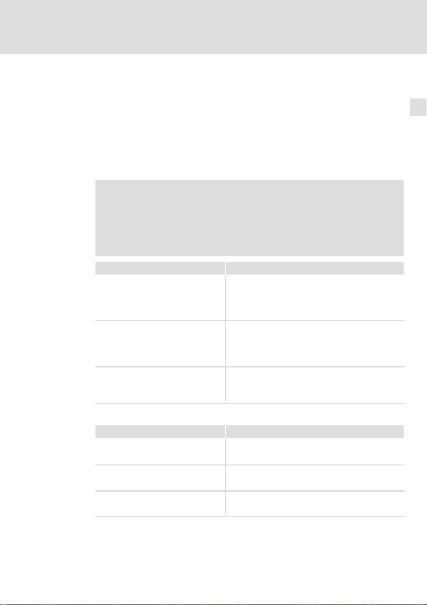
4.4 Electrical installation
L1
N
PE
IPC
Power supply unit
Battery pack (Option)
Capacitor pack (Option)
S
F
N
L1
0
+
~=
0VUSV
PE +24 V
+
1
+
+24
0V
23
Elx7xx−006
24
MA_CPCx8xx DE/EN/FR/ES/IT 2.0
Page 25

Sommaire i
1 Présentation du document 26. . . . . . . . . . . . . . . . . . . . . . . . . . . . . . . . . . . . . . . . .
1.1 Consignes utilisées 26. . . . . . . . . . . . . . . . . . . . . . . . . . . . . . . . . . . . . . . . .
2 Consignes de sécurité 27. . . . . . . . . . . . . . . . . . . . . . . . . . . . . . . . . . . . . . . . . . . . . .
2.1 Consignes générales de sécurité 27. . . . . . . . . . . . . . . . . . . . . . . . . . . . . . .
2.2 Consignes de sécurité pour l’installation selon UL 28. . . . . . . . . . . . . . . .
3 Description du produit 30. . . . . . . . . . . . . . . . . . . . . . . . . . . . . . . . . . . . . . . . . . . . .
3.1 Equipement livré 30. . . . . . . . . . . . . . . . . . . . . . . . . . . . . . . . . . . . . . . . . . .
3.2 Eléments de commande et d’affichage 31. . . . . . . . . . . . . . . . . . . . . . . . .
4 Installation 33. . . . . . . . . . . . . . . . . . . . . . . . . . . . . . . . . . . . . . . . . . . . . . . . . . . . . .
4.1 Remarques importantes 33. . . . . . . . . . . . . . . . . . . . . . . . . . . . . . . . . . . . .
4.2 Encombrements 34. . . . . . . . . . . . . . . . . . . . . . . . . . . . . . . . . . . . . . . . . . . .
4.3 Opérations de montage 34. . . . . . . . . . . . . . . . . . . . . . . . . . . . . . . . . . . . . .
4.4 Installation électrique 35. . . . . . . . . . . . . . . . . . . . . . . . . . . . . . . . . . . . . . .
MA_CPCx8xx DE/EN/FR/ES/IT 2.0
25
Page 26

1
Présentation du document
Consignes utilisées
1 Présentation du document
0Fig. 0Tab. 0
1.1 Consignes utilisées
Pour indiquer des risques et des informations importantes, la présente
documentation utilise les mots et pictogrammes suivants :
Consignes de sécurité
Présentation des consignes de sécurité
Danger !
(Le pictogramme indique le type de risque.)
Explication
(L’explication décrit le risque et les moyens de l’éviter.)
Pictogramme et mot associé Explication
Danger !
Danger !
Stop !
Consignes d’utilisation
Situation dangereuse pour les personnes en raison
d’une tension électrique élevée
Indication d’un danger imminent qui peut avoir pour
conséquences des blessures mortelles ou très graves en
cas de non−respect des consignes de sécurité
correspondantes
Situation dangereuse pour les personnes en raison d’un
danger d’ordre général
Indication d’un danger imminent qui peut avoir pour
conséquences des blessures mortelles ou très graves en
cas de non−respect des consignes de sécurité
correspondantes
Risques de dégâts matériels
Indication d’un risque potentiel qui peut avoir pour
conséquences des dégâts matériels en cas de
non−respect des consignes de sécurité correspondantes
26
Pictogramme et mot associé Explication
Remarque
importante !
Conseil !
Remarque importante pour assurer un fonctionnement
correct
Conseil utile pour faciliter la mise en uvre
Renvoi à une autre documentation
MA_CPCx8xx DE/EN/FR/ES/IT 2.0
Page 27

2 Consignes de sécurité
2.1 Consignes générales de sécurité
Conseils pour assurer votre sécurité
Danger !
Le non−respect des consignes fondamentales de sécurité suivantes
peut entraîner des blessures et des dommages matériels graves.
ƒ Les composants d’entraînement et d’automatisation Lenze ...
... doivent exclusivement être utilisés conformément à leur fonction.
... ne doivent jamais être mis en service si des dommages sont décelés.
... ne doivent jamais être modifiés d’un point de vue technique.
... ne doivent jamais être mis en service s’ils ne sont pas montés
intégralement.
... ne doivent jamais être mis en service sans le capot obligatoire.
... peuvent − selon l’indice de protection − contenir des pièces sous tension, en
mouvement ou en rotation. Les surfaces peuvent être brûlantes.
ƒ Pour les composants d’entraînement et d’automatisation Lenze ...
... utiliser uniquement les accessoires homologués pour le produit.
... utiliser uniquement les pièces détachées d’origine proposées par le
constructeur.
ƒ Respecter les consignes et les indications contenues dans la
documentation concernée.
Il s’agit de la condition préalable pour garantir un fonctionnement sûr et
fiable et pour obtenir les caractéristiques du produit indiquées.
Les procédures à suivre et les plans de raccordement fournis constituent des
recommandations dont l’adéquation avec l’application concernée doit être
vérifiée. Lenze n’assumera aucune responsabilité pour les dommages liés à
un problème d’adéquation des procédures et plans de raccordements
indiqués.
ƒ Les travaux réalisés avec et au niveau des composants d’entraînement et
d’automatisation Lenze ne doivent être exécutés que par un personnel
qualifié et habilité.
Selon les normes CEI 60364 ou CENELEC HD 384, ces personnes doivent ...
... connaître parfaitement l’installation, le montage, la mise en service et le
fonctionnement du produit.
... posséder les qualifications appropriées pour l’exercice de leur activité.
... connaître toutes les prescriptions pour la prévention d’accidents,
directives et lois applicables sur le lieu d’utilisation et être en mesure de les
appliquer.
Consignes de sécurité
Consignes générales de sécurité
2
MA_CPCx8xx DE/EN/FR/ES/IT 2.0
27
Page 28

2
Consignes de sécurité
Consignes de sécurité pour l’installation selon U
L
2.2 Consignes de sécurité pour l’installation selon U
Original − Anglais
Approval
Underwriter Laboratories (UL), UL508 and CSA C22.2 No. 142−M1987, (UL File
Number E236341)
Ratings
ƒ Input 18 ... 30 V DC , max. 4 A
ƒ ACCU−Pack and CAPS−Pack: max 0.6 A
ƒ Max. ambient temperature 50 °C.
ƒ Optional communication ratings:
– RS232−Connection: max. 3 A
– USB−Connection: max. 1 A
– PS/2−Connection: max. 1 A
– LAN−Connection: Standard ISDN or RJ45
– DVI−Connection: max. 1 A
Warnings!
Field Wiring Markings
Wiring Terminal MSTB 2,5/3−STF−5,08:
ƒ Use copper wire only.
ƒ AWG 18 ... AWG 12 (0.82 mm
ƒ Torque 5...7 lb−in (0.5 ... 0.6 Nm)
Battery
ƒ Replace battery with any from the list below, Part No. CR 2450
only. Use of another battery may present a risk of fire or
explosion.
Recommended CR2450 (R/C, BBVC2) types:
Renata Part.no. CR2450N, Sony Corp. part no. CR2450B, Toshiba
part no. CR2450, Varta part no. CR2450, Matsushita part no.
CR2450
ƒ Battery may explode if mistreated. Do not recharge, disassemble,
dispose of in fire or heat above 100 °C (212 °F).
ƒ Dispose of used battery according to the regulation of recycling
or waste.
2
... 3.3 mm2)
L
28
MA_CPCx8xx DE/EN/FR/ES/IT 2.0
Page 29

Consignes de sécurité
Consignes de sécurité pour l’installation selon U
Original − Français
Homologation
Underwriter Laboratories (UL), UL508 et CSA C22.2 n° 142−M1987, (n° de dossier
UL E236341)
Caractéristiques assignées
ƒ Alimentation 18 ... 30 V CC , 4 A max.
ƒ Pack ACCU et CAPS : maximum 0,6 A
ƒ Température ambiante maximale : 50 °C.
ƒ Caractéristiques de communication assignées (option) :
– Port RS232 : maximum 3 A
– Port USB : maximum 1 A
– Port PS/2 : maximum 1 A
– Port LAN : RNIS standard ou RJ45
– Port DVI : maximum 1 A
L
Warnings!
Marquage du câblage à pied d’oeuvre
Bornier de câblage MSTB 2,5/3−STF−5,08 :
ƒ Utiliser exclusivement des conducteurs en cuivre.
ƒ AWG 18 ... AWG 12 (0.82 mm
ƒ Couple de 5 à 7 lb−in (0,5 ... 0,6 Nm)
Batterie
ƒ Remplacer la batterie par l’un des types répertoriés dans la liste
ci−dessous, n° de référence CR 2450 uniquement. L’utilisation
d’une autre batterie présente un risque d’incendie ou
d’explosion.
Types CR2450 recommandés (R/C, BBVC2) :
Renata référence CR2450N, Sony Corp. référence CR2450B,
Toshiba référence CR2450, Varta référence CR2450, Matsushita
référence CR2450
ƒ Toute utilisation non conforme de la batterie entraîne un risque
d’explosion. Ne pas recharger, démonter, jeter au feu ni exposer
la batterie à une chaleur supérieure à 100 °C (212 °F).
ƒ Eliminer la batterie conformément à la réglementation en
vigueur en matière de recyclage ou de traitement des déchets.
2
... 3.3 mm2)
2
MA_CPCx8xx DE/EN/FR/ES/IT 2.0
29
Page 30

3
Description du produit
Equipement livré
3 Description du produit
3.1 Equipement livré
Quantité Désignation
1 PC en armoire électrique
1 Connecteur d’alimentation
1 DVD "PC based Automation"
1 Rapport d’essai
1 Carte d’identification de l’appareil
30
MA_CPCx8xx DE/EN/FR/ES/IT 2.0
Page 31

Eléments de commande et d’affichage
3.2 Eléments de commande et d’affichage
0
Description du produit
0
3
1
2
3
4
5
6
7
8
9
:
;
Pos. Description
PC en armoire électrique
Lecteur de DVD (option)
PS/2
LAN (Ethernet)
MA_CPCx8xx DE/EN/FR/ES/IT 2.0
CPC2700−001
31
Page 32

3
Description du produit
Eléments de commande et d’affichage
DescriptionPos.
LEDs d’état
Error (LED rouge) :
l Cette LED s’allume en cas d’erreur d’alimentation.
HD (LED jaune) :
l Cette LED indique l’accès à un support de données.
Power (LED verte) :
l Cette LED indique que l’appareil est alimenté.
l La LED scintille (
l La LED clignote (
l La LED clignote (
coupure de la tension d’alimentation.
l La LED clignote (
trop faible (exemples : accu vide ou non connecté).
l La LED clignote 4 x par seconde en cas de court−circuit du pack ACCU ou de décharge
complète du pack CAPS.
USB
RS 232
CF−Card
MC−Card
ACU USV
24 V CC
DVI
−
) si une erreur matérielle s’est produite.
−−−−−−−
−−−−−
) lorsque l’option ACU USV est chargée.
−
−−−−−−
) lorsque l’appareil est alimenté via l’option ACU USV en cas de
−−
−−−
) lorsque la tension d’alimentation fournie par l’option ACU USV est
−
32
MA_CPCx8xx DE/EN/FR/ES/IT 2.0
Page 33

4 Installation
4.1 Remarques importantes
ƒ Fixer impérativement l’appareil en position verticale, les orifices de
ventilation vers le haut et vers le bas, afin d’assurer une ventilation
suffisante pour évacuer la chaleur dissipée par l’appareil.
ƒ En utilisant la variante sans ventilateur, la plaque arrière du boîtier doit
être posée sur l’armoire électrique avec une planéité maximale afin
d’assurer une évacuation supplémentaire de la chaleur. La plaque arrière
du boîtier risque d’atteindre des températures allant jusqu’à 65 °C.
Stop !
Court−circuits et décharges électrostatiques
L’appareil comprend des composants sensibles aux court−circuits ou
aux décharges électrostatiques.
Risques encourus :
ƒ Destruction de l’appareil ou de ces composants
Mesures de protection :
ƒ Veiller à ce que l’appareil soit hors tension avant tous travaux sur
celui−ci. Ceci est valable en particulier dans les cas de figure
suivants :
– Avant le raccordement/retrait de connecteurs enfichables
– Avant l’enfichage/le retrait de modules
ƒ Toute personne manipulant des cartes électroniques doit
respecter les mesures relatives aux décharges électrostatiques
(ESD).
ƒ Ne pas toucher les contacts électriques des connecteurs
enfichables.
ƒ Toucher les cartes électroniques uniquement là où il n’y a pas de
contacts électriques et les poser obligatoirement sur des
supports appropriés (exemples : emballage ESD ou mousse
synthétique conductrice).
ƒ Utiliser impérativement les emballages ESD pour transporter ou
stocker des cartes électroniques.
Installation
Remarques importantes
4
MA_CPCx8xx DE/EN/FR/ES/IT 2.0
33
Page 34

4
4.2 Encombrements
Installation
Encombrements
280
Cotes en [mm]
4.3 Opérations de montage
Procéder aux opérations de montage suivantes :
1. Vérifier que l’emplacement correspond aux conditions d’utilisation
indiquées sous "Spécifications techniques".
2. Préparer la plaque de montage de l’armoire électrique.
– Tenir compte des encombrements et des espaces de montage ( 34).
– Assurer un espace suffisant pour accéder au lecteur de DVD.
– Ne pas couvrir les orifices de ventilation.
3. Fixer l’appareil sur la plaque de montage à l’aide des vis.
– Le lieu d’installation et le matériel de montage doivent garantir une
liaison mécanique durable.
178
340
9
21
101
30
310
40
CPC2700−003
34
MA_CPCx8xx DE/EN/FR/ES/IT 2.0
Page 35

4.4 Installation électrique
L1
N
PE
0
+
0VUSV
PE +24 V
23
Installation
Installation électrique
S
F
N
L1
+
~=
1
+
0V
4
+24
PC industriel
Bloc d’alimentation
Pack de piles (option)
Pack de condensateurs (option)
MA_CPCx8xx DE/EN/FR/ES/IT 2.0
Elx7xx−006
35
Page 36

Contenidoi
1 Acerca de esta documentación 37. . . . . . . . . . . . . . . . . . . . . . . . . . . . . . . . . . . . . .
1.1 Indicaciones utilizadas 37. . . . . . . . . . . . . . . . . . . . . . . . . . . . . . . . . . . . . .
2 Instrucciones de seguridad 38. . . . . . . . . . . . . . . . . . . . . . . . . . . . . . . . . . . . . . . . .
2.1 Instrucciones generales de seguridad 38. . . . . . . . . . . . . . . . . . . . . . . . . .
2.2 Instrucciones de seguridad para la instalación según UL 39. . . . . . . . . . .
3 Descripción del producto 41. . . . . . . . . . . . . . . . . . . . . . . . . . . . . . . . . . . . . . . . . .
3.1 Alcance del suministro 41. . . . . . . . . . . . . . . . . . . . . . . . . . . . . . . . . . . . . .
3.2 Elementos de mando y visualización 42. . . . . . . . . . . . . . . . . . . . . . . . . . .
4 Instalación 44. . . . . . . . . . . . . . . . . . . . . . . . . . . . . . . . . . . . . . . . . . . . . . . . . . . . . . .
4.1 Indicaciones importantes 44. . . . . . . . . . . . . . . . . . . . . . . . . . . . . . . . . . . .
4.2 Dimensiones 45. . . . . . . . . . . . . . . . . . . . . . . . . . . . . . . . . . . . . . . . . . . . . . .
4.3 Pasos para el montaje 45. . . . . . . . . . . . . . . . . . . . . . . . . . . . . . . . . . . . . . .
4.4 Instalación eléctrica 46. . . . . . . . . . . . . . . . . . . . . . . . . . . . . . . . . . . . . . . . .
36
MA_CPCx8xx DE/EN/FR/ES/IT 2.0
Page 37

Acerca de esta documentación
Indicaciones utilizadas
1
1 Acerca de esta documentación
0Fig. 0Tab. 0
1.1 Indicaciones utilizadas
Para indicar peligros e información importante, se utilizan en esta
documentación los siguientes términos indicativos y símbolos:
Instrucciones de seguridad
Estructura de las instrucciones de seguridad:
¡Peligro!
(indican el tipo y la gravedad del peligro)
Texto indicativo
(describe el peligro y da instrucciones para evitarlo)
Pictograma y término indicativo Significado
Riesgo de daños personales por voltaje eléctrico
¡Peligro!
¡Peligro!
¡Alto!
Instrucciones de uso
Indica un peligro inminente que puede causar la muerte
o lesiones graves si no se toman las medidas adecuadas.
Riesgo de daños personales por una fuente de riesgo
general
Indica un peligro inminente que puede causar la muerte
o lesiones graves si no se toman las medidas adecuadas.
Peligro de daños materiales
Indica un posible riesgo que puede ocasionar daños
materiales si no se toman las medidas adecuadas.
Pictograma y término indicativo Significado
¡Aviso!
¡Sugerencia!
MA_CPCx8xx DE/EN/FR/ES/IT 2.0
Nota importante para el funcionamiento sin fallos
Sugerencia útil para facilitar la operación
Referencia a otra documentación
37
Page 38

2
Instrucciones de seguridad
Instrucciones generales de seguridad
2 Instrucciones de seguridad
2.1 Instrucciones generales de seguridad
También para su propia seguridad
¡Peligro!
Si no se observan las siguientes instrucciones básicas de seguridad,
pueden ocasionarse serios daños a personas y materiales:
ƒ Los componentes de accionamiento y automatización de Lenze ...
... sólo deben utilizarse de la manera adecuada.
... nunca deben ponerse en funcionamiento si existen daños visibles.
... nunca deben someterse a modificaciones técnicas.
... nunca deben ponerse en funcionamiento si no están completamente
montados.
... nunca deben ponerse en funcionamiento sin las cubiertas necesarias.
... pueden incluir durante y después del funcionamiento, y dependiendo de su
grado de protección, piezas vivas, así como móviles y giratorias. Las
superficies pueden estar calientes.
ƒ Para componentes de accionamiento y automatización de Lenze ...
... sólo utilizar los accesorios permitidos.
... sólo utilizar piezas de recambio originales del fabricante.
ƒ Observe todas las indicaciones de la documentación adjunta y la
documentación correspondiente.
Es requisito esencial para un funcionamiento seguro y sin fallos, así como
para lograr las características declaradas del producto.
Las indicaciones técnicas de procedimiento y secciones de conexión
presentadas en este documento son propuestas, cuya transferabilidad a la
aplicación correspondiente deberá ser comprobada. El fabricante no se hace
responsable de la aptitud de los procedimientos y propuestas de conexión
que se indican.
ƒ Todos los trabajos con y en componentes de accionamiento y
automatización de Lenze sólo deben ser realizados por personal experto
cualificado.
Según IEC 60364 o resp. CENELEC HD 384 se trata de personas, ...
... que conocen la instalación, el montaje, la puesta en marcha y la operación
del producto.
... que disponen de las cualificaciones correspondientes a su trabajo.
... que conocen y saben aplicar todas las normas de prevención de accidentes,
directivas y leyes aplicables en el lugar de uso.
38
MA_CPCx8xx DE/EN/FR/ES/IT 2.0
Page 39

Instrucciones de seguridad
Instrucciones de seguridad para la instalación según U
2
L
2.2 Instrucciones de seguridad para la instalación según U
Original − Inglés
Approval
Underwriter Laboratories (UL), UL508 and CSA C22.2 No. 142−M1987, (UL File
Number E236341)
Ratings
ƒ Input 18 ... 30 V DC , max. 4 A
ƒ ACCU−Pack and CAPS−Pack: max 0.6 A
ƒ Max. ambient temperature 50 °C.
ƒ Optional communication ratings:
– RS232−Connection: max. 3 A
– USB−Connection: max. 1 A
– PS/2−Connection: max. 1 A
– LAN−Connection: Standard ISDN or RJ45
– DVI−Connection: max. 1 A
Warnings!
Field Wiring Markings
Wiring Terminal MSTB 2,5/3−STF−5,08:
ƒ Use copper wire only.
ƒ AWG 18 ... AWG 12 (0.82 mm
ƒ Torque 5...7 lb−in (0.5 ... 0.6 Nm)
Battery
ƒ Replace battery with any from the list below, Part No. CR 2450
only. Use of another battery may present a risk of fire or
explosion.
Recommended CR2450 (R/C, BBVC2) types:
Renata Part.no. CR2450N, Sony Corp. part no. CR2450B, Toshiba
part no. CR2450, Varta part no. CR2450, Matsushita part no.
CR2450
ƒ Battery may explode if mistreated. Do not recharge, disassemble,
dispose of in fire or heat above 100 °C (212 °F).
ƒ Dispose of used battery according to the regulation of recycling or
waste.
2
... 3.3 mm2)
L
MA_CPCx8xx DE/EN/FR/ES/IT 2.0
39
Page 40

2
Instrucciones de seguridad
Instrucciones de seguridad para la instalación según U
Original − Francés
Homologation
Underwriter Laboratories (UL), UL508 et CSA C22.2 n° 142−M1987, (n° de dossier
UL E236341)
Caractéristiques assignées
ƒ Alimentation 18 ... 30 V CC , 4 A max.
ƒ Pack ACCU et CAPS : maximum 0,6 A
ƒ Température ambiante maximale : 50 °C.
ƒ Caractéristiques de communication assignées (option) :
L
– Port RS232 : maximum 3 A
– Port USB : maximum 1 A
– Port PS/2 : maximum 1 A
– Port LAN : RNIS standard ou RJ45
– Port DVI : maximum 1 A
40
Warnings!
Marquage du câblage à pied d’oeuvre
Bornier de câblage MSTB 2,5/3−STF−5,08 :
ƒ Utiliser exclusivement des conducteurs en cuivre.
ƒ AWG 18 ... AWG 12 (0.82 mm
ƒ Couple de 5 à 7 lb−in (0,5 ... 0,6 Nm)
Batterie
ƒ Remplacer la batterie par l’un des types répertoriés dans la liste
ci−dessous, n° de référence CR 2450 uniquement. L’utilisation
d’une autre batterie présente un risque d’incendie ou d’explosion.
Types CR2450 recommandés (R/C, BBVC2) :
Renata référence CR2450N, Sony Corp. référence CR2450B,
Toshiba référence CR2450, Varta référence CR2450, Matsushita
référence CR2450
ƒ Toute utilisation non conforme de la batterie entraîne un risque
d’explosion. Ne pas recharger, démonter, jeter au feu ni exposer la
batterie à une chaleur supérieure à 100 °C (212 °F).
ƒ Eliminer la batterie conformément à la réglementation en vigueur
en matière de recyclage ou de traitement des déchets.
2
... 3.3 mm2)
MA_CPCx8xx DE/EN/FR/ES/IT 2.0
Page 41

3 Descripción del producto
3.1 Alcance del suministro
Cantidad Denominación
1 PC para armarios eléctricos
1 Conector para el suministro de voltaje
1 DVD "PC based Automation"
1 Informe de ensayo
1 Pasaporte del equipo
Descripción del producto
Alcance del suministro
3
MA_CPCx8xx DE/EN/FR/ES/IT 2.0
41
Page 42

3
3.2 Elementos de mando y visualización
Descripción del producto
Elementos de mando y visualización
0
1
2
3
0
4
5
6
7
8
9
:
;
42
Pos. Descripción
PC para armarios eléctricos
Unidad de DVD (opcional)
PS/2
LAN (Ethernet)
CPC2700−001
MA_CPCx8xx DE/EN/FR/ES/IT 2.0
Page 43

Descripción del producto
Elementos de mando y visualización
DescripciónPos.
LEDs de estado
Error (rojo):
l Se enciende cuando hay un error en el suministro eléctrico.
HD (amarillo):
l Indica el acceso a un medio de memoria.
Power (verde):
l Se enciende cuando hay suministro de voltaje.
l Destellea (
l Parpadea (
l Parpadea (
alimentado por el SAI ACU.
l Parpadea (
batería vacía o no existente).
l Parpadea 4 veces por segundo cuando el ACCU−PACK ha generado un cortocircuito o el
CAPS−PACK está totalmente vacío.
USB
RS 232
CF Card
MC Card
SAI ACU
24 V DC
DVI
−
), cuando hay un error de hardware.
−−−−−−−
−−−−−
), cuando se está cargando el SAI ACU (opcional).
−
−−−−−−
), cuando ha fallado el suministro de voltaje y el equipo está siendo
−−
−−−
), cuando el suministro de voltaje desde el SAI ACU es insuficiente (p.e.
−
3
MA_CPCx8xx DE/EN/FR/ES/IT 2.0
43
Page 44

4
Instalación
Indicaciones importantes
4 Instalación
4.1 Indicaciones importantes
ƒ Para garantizar una eliminación de calor suficiente, el equipo sólo debe
montarse en posición vertical, con las aberturas de ventilación hacia
arriba y abajo, atornillado a una pared del armario eléctrico.
ƒ En la variante sin ventilador, la placa trasera de la carcasa debe estar
colocada de forma llana sobre la pared del armario eléctrico para poder
eliminar calor a través de ella también. La placa trasera de la carcasa
puede alcanzar una temperatura superficial de hasta 65 °C.
¡Alto!
Cortocircuito y descargas estáticas
El equipo contiene elementos que pueden resultar dañados en caso
de cortocircuito o descarga estática.
Posibles consecuencias:
ƒ El equipo o partes de éste podrían resultar dañados.
Medidas de protección:
ƒ Siempre desconectar el suministro de voltaje al trabajar en el
equipo. Esto es especialmente de aplicación:
– antes de enchufar/desenchufar conectores.
– antes de enchufar/desenchufar módulos.
ƒ Todas las personas que trabajen con subconjuntos planos, deben
tener en cuenta las medidas relativas a las descargas
electrostáticas (ESD).
ƒ No se deben tocar los contactos de conectores enchufables.
ƒ Los subconjuntos planos sólo deben tocarse en puntos libres de
contacto y colocarse solamente sobre bases adecuadas (p.e.
sobre embalaje ESD o goma−espuma conductora).
ƒ Los subconjuntos planos sólo deben ser transportados en
embalajes ESD.
44
MA_CPCx8xx DE/EN/FR/ES/IT 2.0
Page 45

4.2 Dimensiones
Instalación
Dimensiones
4
280
178
Todas las medidas en milímetros.
4.3 Pasos para el montaje
Para el montaje, proceda de la siguiente manera:
1. Controle que el lugar de montaje garantice las condiciones de uso que se
indican en los datos técnicos.
2. Preparar la placa de montaje del armario eléctrico.
– Observar dimensiones y espacios libres para el montaje ( 45).
– Debe haber espacio suficiente para cargar/descargar la unidad de DVD.
– Las aberturas de ventilación no deben estar tapadas.
3. Atornillar el equipo en la placa de montaje.
– El lugar y el material de montaje deben garantizar las uniones
mecánicas de forma duradera.
340
9
21
101
30
310
40
CPC2700−003
MA_CPCx8xx DE/EN/FR/ES/IT 2.0
45
Page 46

4
Instalación
Instalación eléctrica
4.4 Instalación eléctrica
L1
N
PE
IPC
Fuente de red
Pack de baterías (opcional)
Pack de condensadores (opcional)
S
F
N
L1
0
+
~=
0VUSV
PE +24 V
+
1
+
+24
0V
23
Elx7xx−006
46
MA_CPCx8xx DE/EN/FR/ES/IT 2.0
Page 47

Sommario i
1 Informazioni sul manuale 48. . . . . . . . . . . . . . . . . . . . . . . . . . . . . . . . . . . . . . . . . .
1.1 Avvertenze utilizzate 48. . . . . . . . . . . . . . . . . . . . . . . . . . . . . . . . . . . . . . . .
2 Informazioni sulla sicurezza 49. . . . . . . . . . . . . . . . . . . . . . . . . . . . . . . . . . . . . . . .
2.1 Note generali di sicurezza 49. . . . . . . . . . . . . . . . . . . . . . . . . . . . . . . . . . . .
2.2 Informazioni sulla sicurezza per l’installazione secondo UL o UR 51. . . .
3 Descrizione del prodotto 53. . . . . . . . . . . . . . . . . . . . . . . . . . . . . . . . . . . . . . . . . . .
3.1 Oggetto della fornitura 53. . . . . . . . . . . . . . . . . . . . . . . . . . . . . . . . . . . . . .
3.2 Elementi di comando e visualizzazione 54. . . . . . . . . . . . . . . . . . . . . . . . .
4 Installazione 56. . . . . . . . . . . . . . . . . . . . . . . . . . . . . . . . . . . . . . . . . . . . . . . . . . . . .
4.1 Note importanti 56. . . . . . . . . . . . . . . . . . . . . . . . . . . . . . . . . . . . . . . . . . . .
4.2 Dimensioni 57. . . . . . . . . . . . . . . . . . . . . . . . . . . . . . . . . . . . . . . . . . . . . . . .
4.3 Procedura di montaggio 57. . . . . . . . . . . . . . . . . . . . . . . . . . . . . . . . . . . . .
4.4 Installazione elettrica 58. . . . . . . . . . . . . . . . . . . . . . . . . . . . . . . . . . . . . . .
MA_CPCx8xx DE/EN/FR/ES/IT 2.0
47
Page 48

1
Informazioni sul manuale
Avvertenze utilizzate
1 Informazioni sul manuale
0Fig. 0Tab. 0
1.1 Avvertenze utilizzate
Per segnalare pericoli ed informazioni importanti, nella presente
documentazione sono riportati i seguenti simboli e parole di segnalazione:
Note di sicurezza
Struttura delle note di sicurezza:
Pericolo!
(indica il tipo e la gravità del pericolo)
Testo della nota
(descrive il pericolo e fornisce indicazioni su come può essere
evitato)
Simbolo e parola di segnalazione Significato
Pericolo!
Pericolo!
Stop!
Note di utilizzo
Pericolo di danni alle persone dovuti a tensione elettrica
Segnala una situazione di pericolo che può provocare
morte o gravi lesioni se non vengono osservate le
necessarie misure precauzionali.
Pericolo di danni alle persone dovuti a una fonte
generica di pericolo
Segnala una situazione di pericolo che può provocare
morte o gravi lesioni se non vengono osservate le
necessarie misure precauzionali.
Pericolo di danni materiali
Segnala un possibile pericolo che può provocare danni
materiali se non vengono osservate le necessarie misure
precauzionali.
48
Simbolo e parola di segnalazione Significato
Avvertenza:
Suggerimento:
Avvertenza importante per assicurare un corretto
funzionamento dell’apparecchiatura
Utile suggerimento per un più semplice utilizzo
Rimando ad altra documentazione
MA_CPCx8xx DE/EN/FR/ES/IT 2.0
Page 49

Informazioni sulla sicurezza
2 Informazioni sulla sicurezza
2.1 Note generali di sicurezza
Anche per la propria sicurezza
Pericolo!
La mancata osservanza delle seguenti misure fondamentali di
sicurezza può provocare gravi danni a persone e cose.
ƒ Relativamente ai componenti di azionamento e automazione Lenze,
osservare quanto segue:
utilizzare tali componenti esclusivamente in conformità agli usi preposti
non mettere mai in funzione tali componenti in caso di danni evidenti
non effettuare in nessun caso modifiche tecniche
non mettere mai in funzione tali componenti in caso di montaggio
incompleto
non azionare mai tali componenti senza le coperture richieste
in funzione del grado di protezione, durante o dopo il funzionamento tali
componenti possono presentare parti sotto tensione, mobili o rotanti; le
superfici possono essere ustionanti.
ƒ Per i componenti di azionamento e automazione Lenze, utilizzare ...
... solo gli accessori omologati
... solo le parti di ricambio originali del costruttore.
ƒ Osservare tutte le istruzioni e avvertenze fornite nella documentazione in
dotazione e pertinente.
Solo in questo modo è possibile assicurare un funzionamento sicuro e senza
problemi, nonché caratteristiche del prodotto conformi alle specifiche.
Le specifiche, le procedure e gli schemi di collegamento forniti nel presente
documento sono suggerimenti per i quali è necessario verificare
l’applicabilità al singolo caso. Il produttore non si assume alcuna
responsabilità per l’idoneità delle procedure e degli schemi di collegamento
proposti.
ƒ Tutti gli interventi relativi ai componenti di azionamento e automazione
Lenze devono essere eseguiti esclusivamente da personale specializzato
qualificato.
Secondo la normativa IEC 60364, ovvero CENELEC HD 384, per personale
qualificato si intende:
personale che ha acquisito familiarità con l’installazione, il montaggio, la
messa in servizio e il funzionamento del prodotto;
personale che dispone delle necessarie qualifiche grazie all’esperienza
maturata;
2
Note generali di sicurezza
MA_CPCx8xx DE/EN/FR/ES/IT 2.0
49
Page 50

2
Informazioni sulla sicurezza
Note generali di sicurezza
personale che conosce ed è in grado di applicare tutte le disposizioni
antinfortunistiche, le direttive e le norme vigenti nel luogo di installazione.
50
MA_CPCx8xx DE/EN/FR/ES/IT 2.0
Page 51

Informazioni sulla sicurezza
Informazioni sulla sicurezza per l’installazione secondo UL o U
2
R
2.2 Informazioni sulla sicurezza per l’installazione secondo UL o U
Originale − Inglese
Approval
Underwriter Laboratories (UL), UL508 and CSA C22.2 No. 142−M1987, (UL File
Number E236341)
Ratings
ƒ Input 18 ... 30 V DC , max. 4 A
ƒ ACCU−Pack and CAPS−Pack: max 0.6 A
ƒ Max. ambient temperature 50 °C.
ƒ Optional communication ratings:
– RS232−Connection: max. 3 A
– USB−Connection: max. 1 A
– PS/2−Connection: max. 1 A
– LAN−Connection: Standard ISDN or RJ45
– DVI−Connection: max. 1 A
Warnings!
Field Wiring Markings
Wiring Terminal MSTB 2,5/3−STF−5,08:
ƒ Use copper wire only.
ƒ AWG 18 ... AWG 12 (0.82 mm
ƒ Torque 5...7 lb−in (0.5 ... 0.6 Nm)
Battery
ƒ Replace battery with any from the list below, Part No. CR 2450
only. Use of another battery may present a risk of fire or
explosion.
Recommended CR2450 (R/C, BBVC2) types:
Renata Part.no. CR2450N, Sony Corp. part no. CR2450B, Toshiba
part no. CR2450, Varta part no. CR2450, Matsushita part no.
CR2450
ƒ Battery may explode if mistreated. Do not recharge, disassemble,
dispose of in fire or heat above 100 °C (212 °F).
ƒ Dispose of used battery according to the regulation of recycling
or waste.
2
... 3.3 mm2)
R
MA_CPCx8xx DE/EN/FR/ES/IT 2.0
51
Page 52

2
Informazioni sulla sicurezza
Informazioni sulla sicurezza per l’installazione secondo UL o U
Originale − Francese
Homologation
Underwriter Laboratories (UL), UL508 et CSA C22.2 n° 142−M1987, (n° de dossier
UL E236341)
Caractéristiques assignées
ƒ Alimentation 18 ... 30 V CC , 4 A max.
ƒ Pack ACCU et CAPS : maximum 0,6 A
ƒ Température ambiante maximale : 50 °C.
ƒ Caractéristiques de communication assignées (option) :
R
– Port RS232 : maximum 3 A
– Port USB : maximum 1 A
– Port PS/2 : maximum 1 A
– Port LAN : RNIS standard ou RJ45
– Port DVI : maximum 1 A
52
Warnings!
Marquage du câblage à pied d’oeuvre
Bornier de câblage MSTB 2,5/3−STF−5,08 :
ƒ Utiliser exclusivement des conducteurs en cuivre.
ƒ AWG 18 ... AWG 12 (0.82 mm
ƒ Couple de 5 à 7 lb−in (0,5 ... 0,6 Nm)
Batterie
ƒ Remplacer la batterie par l’un des types répertoriés dans la liste
ci−dessous, n° de référence CR 2450 uniquement. L’utilisation
d’une autre batterie présente un risque d’incendie ou
d’explosion.
Types CR2450 recommandés (R/C, BBVC2) :
Renata référence CR2450N, Sony Corp. référence CR2450B,
Toshiba référence CR2450, Varta référence CR2450, Matsushita
référence CR2450
ƒ Toute utilisation non conforme de la batterie entraîne un risque
d’explosion. Ne pas recharger, démonter, jeter au feu ni exposer
la batterie à une chaleur supérieure à 100 °C (212 °F).
ƒ Eliminer la batterie conformément à la réglementation en
vigueur en matière de recyclage ou de traitement des déchets.
2
... 3.3 mm2)
MA_CPCx8xx DE/EN/FR/ES/IT 2.0
Page 53

3 Descrizione del prodotto
3.1 Oggetto della fornitura
Quantità Denominazione
1 PC per armadio elettrico
1 Connettore di collegamento per alimentazione
1 DVD "PC based Automation"
1 Rapporto di prova
1 Libretto dell’apparecchio
Descrizione del prodotto
Oggetto della fornitura
3
MA_CPCx8xx DE/EN/FR/ES/IT 2.0
53
Page 54

3
3.2 Elementi di comando e visualizzazione
Descrizione del prodotto
Elementi di comando e visualizzazione
0
1
2
3
0
4
5
6
7
8
9
:
;
54
Pos. Descrizione
PC per armadio elettrico
Unità DVD (opzionale)
PS/2
LAN (Ethernet)
CPC2700−001
MA_CPCx8xx DE/EN/FR/ES/IT 2.0
Page 55

Descrizione del prodotto
Elementi di comando e visualizzazione
DescrizionePos.
LED di stato
Error (rosso):
l Acceso quando si è verificato un errore nell’alimentazione di corrente;
HD (giallo):
l Mostra l’accesso a un supporto di memoria.
Power (verde):
l Acceso quando l’alimentazione è disponibile.
l Lampeggia in modo intermittente (
l Lampeggia (
carica.
l Lampeggia (
corrente dal gruppo di continuità a batteria.
l Lampeggia (
continuità (ad es. batteria scarica o mancante).
l Lampeggia 4 volte al secondo quando il gruppo batterie (ACCU−PACK) provoca un
cortocircuito o il gruppo condensatore (CAPS−PACK) è completamente scarico.
USB
RS 232
Scheda CF
Scheda MC
ACU UPS
24 V
DVI
−−−−−
) quando il sistema ACU UPS (gruppo di continuità opzionale) è in
−
−−−−−−
) quando l’alimentazione di rete si è interrotta e il dispositivo riceve
−−
−−−
) in caso di tensione d’alimentazione troppo bassa dal gruppo di
−
−
) in caso di guasto all’hardware.
−−−−−−−
3
MA_CPCx8xx DE/EN/FR/ES/IT 2.0
55
Page 56

4
Installazione
Note importanti
4 Installazione
4.1 Note importanti
ƒ Per assicurare una dissipazione di calore sufficiente, l’apparecchio può
essere avvitato alla parete dell’armadio elettrico solo in verticale, con le
aperture di ventilazione sopra o sotto.
ƒ In caso di variante senza ventola, la piastra posteriore della custodia deve
essere collocata piana contro la parete dell’armadio elettrico, per
dissipare ulteriore calore. La piastra posteriore può raggiungere una
temperatura superficiale di massimo 65 °C.
Stop!
Cortocircuito e scariche elettrostatiche
L’apparecchio include componenti che sono in pericolo in caso di
cortocircuito o scariche elettrostatiche.
Possibili conseguenze:
ƒ Distruzione dell’apparecchio o di sue parti.
Misure di protezione:
ƒ Quando si eseguono interventi sull’apparecchio, scollegare
sempre l’alimentazione. Questo vale in particolare:
– prima di collegare / scollegare connettori a innesto.
– prima di inserire / disinserire moduli.
ƒ Tutte le persone che maneggiano schede a circuiti stampati
devono osservare le misure di protezione ESD.
ƒ Non toccare i contatti di connettori a innesto.
ƒ Le schede a circuiti stampati possono essere toccate solo nei
punti privi di contatti e collocate solo su superfici di appoggio
adeguate (ad es. su materiale d’imballaggio ESD o schiuma
conduttiva).
ƒ Le schede a circuiti stampati possono essere trasportate e
conservate solo in imballaggi ESD idonei.
56
MA_CPCx8xx DE/EN/FR/ES/IT 2.0
Page 57

4.2 Dimensioni
Installazione
Dimensioni
4
280
178
Tutte le quote sono in millimetri.
4.3 Procedura di montaggio
Per il montaggio, procedere nel seguente modo:
1. Verificare che il luogo di installazione sia conforme alle condizioni
operative riportate nei dati tecnici.
2. Preparare la piastra di montaggio per armadio elettrico.
– Osservare le dimensioni e le quote di rispetto ( 57).
– Deve esservi spazio sufficiente per inserire i dischi nell’unità DVD ed
espellerli da quest’ultima.
– Le aperture di ventilazione non devono essere ostruite.
3. Avvitare l’apparecchio sulla piastra di montaggio.
– La posizione di montaggio e il materiale di installazione devono
garantire una connessione meccanica permanente.
340
9
21
101
30
310
40
CPC2700−003
MA_CPCx8xx DE/EN/FR/ES/IT 2.0
57
Page 58

4
Installazione
Installazione elettrica
4.4 Installazione elettrica
L1
N
PE
IPC
Alimentatore
Gruppo batterie (opzionale)
Gruppo condensatore (opzionale)
S
F
N
L1
0
+
~=
0VUSV
PE +24 V
+
1
+
+24
0V
23
Elx7xx−006
58
MA_CPCx8xx DE/EN/FR/ES/IT 2.0
Page 59

F
(
Ê
ü
© 02/2014
Lenze Automation GmbH
Postfach 10 13 52, D−31763 Hameln
Hans−Lenze−Str. 1, D−31855 Aerzen
Germany
+495154 82−0
+495154 82−2800
lenze@lenze.com
www.lenze.com
Service Lenze Service GmbH
(
Ê
Breslauer Straße 3, D−32699 Extertal
Germany
0080002446877 (24 h helpline)
+49515482−1112
service@lenze.com
MA_CPCx8xx § .ND< § DE/EN/FR/ES/IT § 2.0 § TD06
10987654321
 Loading...