

Page 1
Automation Systems
Controller-based
Automation
Visualisation
_ _ _ _ _ _ _ _ _ _ _ _ _ _ _ _ _ _ _ _ _ _ _ _ _ _ _ _ _ _
System Manual EN
Ä.O<Aä>
13462732
L
Page 2

Contents
_ _ _ _ _ _ _ _ _ _ _ _ _ _ _ _ _ _ _ _ _ _ _ _ _ _ _ _ _ _ _ _ _ _ _ _ _ _ _ _ _ _ _ _ _ _ _ _ _ _ _ _ _ _ _ _ _ _ _ _ _ _ _ _
1 About this documentation _ _ _ _ _ _ _ _ _ _ _ _ _ _ _ _ _ _ _ _ _ _ _ _ _ _ _ _ _ _ _ _ _ _ _ _ _ _ _ 4
1.1 Document history _ _ _ _ _ _ _ _ _ _ _ _ _ _ _ _ _ _ _ _ _ _ _ _ _ _ _ _ _ _ _ _ _ _ _ _ _ _ _ _ _ _ _ _ 6
1.2 Conventions used _ _ _ _ _ _ _ _ _ _ _ _ _ _ _ _ _ _ _ _ _ _ _ _ _ _ _ _ _ _ _ _ _ _ _ _ _ _ _ _ _ _ _ _ 7
1.3 Terminology used _ _ _ _ _ _ _ _ _ _ _ _ _ _ _ _ _ _ _ _ _ _ _ _ _ _ _ _ _ _ _ _ _ _ _ _ _ _ _ _ _ _ _ _ 8
1.4 Definition of the notes used _ _ _ _ _ _ _ _ _ _ _ _ _ _ _ _ _ _ _ _ _ _ _ _ _ _ _ _ _ _ _ _ _ _ _ _ _ _ 11
2Safety instructions _ _ _ _ _ _ _ _ _ _ _ _ _ _ _ _ _ _ _ _ _ _ _ _ _ _ _ _ _ _ _ _ _ _ _ _ _ _ _ _ _ _ _ _ 12
3 Controller-based Automation: Central motion control _ _ _ _ _ _ _ _ _ _ _ _ _ _ _ _ _ _ _ _ _ _ _ _ 13
4System description _ _ _ _ _ _ _ _ _ _ _ _ _ _ _ _ _ _ _ _ _ _ _ _ _ _ _ _ _ _ _ _ _ _ _ _ _ _ _ _ _ _ _ 15
4.1 Visualisation system structure _ _ _ _ _ _ _ _ _ _ _ _ _ _ _ _ _ _ _ _ _ _ _ _ _ _ _ _ _ _ _ _ _ _ _ _ _ 15
4.1.1 Stand-alone application _ _ _ _ _ _ _ _ _ _ _ _ _ _ _ _ _ _ _ _ _ _ _ _ _ _ _ _ _ _ _ _ _ _ _ _ 16
4.1.2 Integrated control system _ _ _ _ _ _ _ _ _ _ _ _ _ _ _ _ _ _ _ _ _ _ _ _ _ _ _ _ _ _ _ _ _ _ _ 17
4.1.3 Client/server system _ _ _ _ _ _ _ _ _ _ _ _ _ _ _ _ _ _ _ _ _ _ _ _ _ _ _ _ _ _ _ _ _ _ _ _ _ _ 18
4.2 System components _ _ _ _ _ _ _ _ _ _ _ _ _ _ _ _ _ _ _ _ _ _ _ _ _ _ _ _ _ _ _ _ _ _ _ _ _ _ _ _ _ _ _ 19
4.2.1 Controller: "Controller-based Automation" (control technology version 3.x) _ _ _ _ _ _ _ 19
4.2.2 Industrial PCs (IPC): "PC-based Automation" (control technology version 2.x) _ _ _ _ _ _ _ 19
4.2.3 Runtime software _ _ _ _ _ _ _ _ _ _ _ _ _ _ _ _ _ _ _ _ _ _ _ _ _ _ _ _ _ _ _ _ _ _ _ _ _ _ _ 20
4.2.3.1 "Logic" and "Motion" runtime software _ _ _ _ _ _ _ _ _ _ _ _ _ _ _ _ _ _ _ _ _ 20
4.2.3.2 "Visu" runtime software _ _ _ _ _ _ _ _ _ _ _ _ _ _ _ _ _ _ _ _ _ _ _ _ _ _ _ _ _ 21
4.2.3.3 "Visu" runtime software - licence information _ _ _ _ _ _ _ _ _ _ _ _ _ _ _ _ _ 25
4.2.4 Field devices _ _ _ _ _ _ _ _ _ _ _ _ _ _ _ _ _ _ _ _ _ _ _ _ _ _ _ _ _ _ _ _ _ _ _ _ _ _ _ _ _ _ 26
4.2.4.1 Direct access to the field devices _ _ _ _ _ _ _ _ _ _ _ _ _ _ _ _ _ _ _ _ _ _ _ _ _ 27
4.2.4.2 Access to the control system and the field devices connected _ _ _ _ _ _ _ _ _ 28
4.2.5 Engineering tool»VisiWinNET®« _ _ _ _ _ _ _ _ _ _ _ _ _ _ _ _ _ _ _ _ _ _ _ _ _ _ _ _ _ _ _ 29
4.2.5.1 »VisiWinNET®« Smart _ _ _ _ _ _ _ _ _ _ _ _ _ _ _ _ _ _ _ _ _ _ _ _ _ _ _ _ _ _ _ 29
4.2.6 Backup of visualisation data (UPS functionality) _ _ _ _ _ _ _ _ _ _ _ _ _ _ _ _ _ _ _ _ _ _ _ 31
4.3 Network topologies _ _ _ _ _ _ _ _ _ _ _ _ _ _ _ _ _ _ _ _ _ _ _ _ _ _ _ _ _ _ _ _ _ _ _ _ _ _ _ _ _ _ _ 32
4.3.1 Channels _ _ _ _ _ _ _ _ _ _ _ _ _ _ _ _ _ _ _ _ _ _ _ _ _ _ _ _ _ _ _ _ _ _ _ _ _ _ _ _ _ _ _ _ 32
4.3.2 Browsing variables _ _ _ _ _ _ _ _ _ _ _ _ _ _ _ _ _ _ _ _ _ _ _ _ _ _ _ _ _ _ _ _ _ _ _ _ _ _ _ 34
4.3.3 EtherCAT® _ _ _ _ _ _ _ _ _ _ _ _ _ _ _ _ _ _ _ _ _ _ _ _ _ _ _ _ _ _ _ _ _ _ _ _ _ _ _ _ _ _ _ 35
4.3.4 CANopen® _ _ _ _ _ _ _ _ _ _ _ _ _ _ _ _ _ _ _ _ _ _ _ _ _ _ _ _ _ _ _ _ _ _ _ _ _ _ _ _ _ _ _ 37
4.3.5 PROFIBUS® _ _ _ _ _ _ _ _ _ _ _ _ _ _ _ _ _ _ _ _ _ _ _ _ _ _ _ _ _ _ _ _ _ _ _ _ _ _ _ _ _ _ _ 40
4.3.6 PROFINET® _ _ _ _ _ _ _ _ _ _ _ _ _ _ _ _ _ _ _ _ _ _ _ _ _ _ _ _ _ _ _ _ _ _ _ _ _ _ _ _ _ _ _ 43
4.3.7 Ethernet _ _ _ _ _ _ _ _ _ _ _ _ _ _ _ _ _ _ _ _ _ _ _ _ _ _ _ _ _ _ _ _ _ _ _ _ _ _ _ _ _ _ _ _ 46
4.3.8 Further bus systems _ _ _ _ _ _ _ _ _ _ _ _ _ _ _ _ _ _ _ _ _ _ _ _ _ _ _ _ _ _ _ _ _ _ _ _ _ _ 49
4.2.5.2 »VisiWinNET®« Professional _ _ _ _ _ _ _ _ _ _ _ _ _ _ _ _ _ _ _ _ _ _ _ _ _ _ _ 30
4.2.5.3 Visualisation kit _ _ _ _ _ _ _ _ _ _ _ _ _ _ _ _ _ _ _ _ _ _ _ _ _ _ _ _ _ _ _ _ _ _ 30
4.2.6.1 Capacitor pack (CAPS-PACK) _ _ _ _ _ _ _ _ _ _ _ _ _ _ _ _ _ _ _ _ _ _ _ _ _ _ _ 31
4.2.6.2 Battery pack (ACCU-PACK) _ _ _ _ _ _ _ _ _ _ _ _ _ _ _ _ _ _ _ _ _ _ _ _ _ _ _ _ 31
2 Lenze · Controller-based Automation - Visualisation · System Manual · DMS 1.5 EN · 04/2014 · TD17
Page 3

Contents
_ _ _ _ _ _ _ _ _ _ _ _ _ _ _ _ _ _ _ _ _ _ _ _ _ _ _ _ _ _ _ _ _ _ _ _ _ _ _ _ _ _ _ _ _ _ _ _ _ _ _ _ _ _ _ _ _ _ _ _ _ _ _ _
5 Commissioning _ _ _ _ _ _ _ _ _ _ _ _ _ _ _ _ _ _ _ _ _ _ _ _ _ _ _ _ _ _ _ _ _ _ _ _ _ _ _ _ _ _ _ _ _ 50
6 Remote maintenance and diagnostics _ _ _ _ _ _ _ _ _ _ _ _ _ _ _ _ _ _ _ _ _ _ _ _ _ _ _ _ _ _ _ _ _ 51
6.1 Remote maintenance with an external router _ _ _ _ _ _ _ _ _ _ _ _ _ _ _ _ _ _ _ _ _ _ _ _ _ _ _ _ _ 51
6.2 Remote maintenance with a separate remote PC _ _ _ _ _ _ _ _ _ _ _ _ _ _ _ _ _ _ _ _ _ _ _ _ _ _ _ 52
6.3 Log-in on an IPC of the x800 device series (PC-based automation) _ _ _ _ _ _ _ _ _ _ _ _ _ _ _ _ _ _ 53
6.4 Computer access via Telnet _ _ _ _ _ _ _ _ _ _ _ _ _ _ _ _ _ _ _ _ _ _ _ _ _ _ _ _ _ _ _ _ _ _ _ _ _ _ _ 53
6.5 File transfer via FTP _ _ _ _ _ _ _ _ _ _ _ _ _ _ _ _ _ _ _ _ _ _ _ _ _ _ _ _ _ _ _ _ _ _ _ _ _ _ _ _ _ _ _ 54
6.6 Web server/»WebConfig« _ _ _ _ _ _ _ _ _ _ _ _ _ _ _ _ _ _ _ _ _ _ _ _ _ _ _ _ _ _ _ _ _ _ _ _ _ _ _ _ 55
6.7 »Virtual Network Computing (VNC)«: Redirecting screen contents/entries _ _ _ _ _ _ _ _ _ _ _ _ _ 56
7Appendix _ _ _ _ _ _ _ _ _ _ _ _ _ _ _ _ _ _ _ _ _ _ _ _ _ _ _ _ _ _ _ _ _ _ _ _ _ _ _ _ _ _ _ _ _ _ _ _ _ 57
7.1 Information regarding the FDA conformance _ _ _ _ _ _ _ _ _ _ _ _ _ _ _ _ _ _ _ _ _ _ _ _ _ _ _ _ _ 57
8Glossary _ _ _ _ _ _ _ _ _ _ _ _ _ _ _ _ _ _ _ _ _ _ _ _ _ _ _ _ _ _ _ _ _ _ _ _ _ _ _ _ _ _ _ _ _ _ _ _ _ 58
Index _ _ _ _ _ _ _ _ _ _ _ _ _ _ _ _ _ _ _ _ _ _ _ _ _ _ _ _ _ _ _ _ _ _ _ _ _ _ _ _ _ _ _ _ _ _ _ _ _ _ _ 61
Your opinion is important to us _ _ _ _ _ _ _ _ _ _ _ _ _ _ _ _ _ _ _ _ _ _ _ _ _ _ _ _ _ _ _ _ _ _ _ _ _ 63
Lenze · Controller-based Automation - Visualisation · System Manual · DMS 1.5 EN · 04/2014 · TD17 3
Page 4

1 About this documentation
_ _ _ _ _ _ _ _ _ _ _ _ _ _ _ _ _ _ _ _ _ _ _ _ _ _ _ _ _ _ _ _ _ _ _ _ _ _ _ _ _ _ _ _ _ _ _ _ _ _ _ _ _ _ _ _ _ _ _ _ _ _ _ _
1 About this documentation
This system manual contains some information relating to the system structure ...
• of the controller-based visualisation technology (control technology release 3.x), and
• of the PC-based visualisation technology (control technology release 2.x).
As a higher-level system manual, the document provides an overview of the visualisation
technology's system components and their interaction.
Detailed information on the components, target systems and the Engineering software to be used
can be found in the manuals for the related components and devices as well as in the
communication manuals of the supported bus systems.
This manual is part of the "Controller-based Automation" manual collection. It consists of the
following sets of documentation:
Documentation type Subject
System manuals System overview/sample topologies
• Controller-based Automation
• Visualisation
Communication manuals
Online helps
Reference manuals
Online helps
Software manuals
Online helps
Bus systems
• Controller-based Automation EtherCAT®
• Controller-based Automation CANopen®
• Controller-based Automation PROFIBUS®
• Controller-based Automation PROFINET®
Lenze Controller:
• Controller 3200 C
• Controller c300
• Controller p300
• Controller p500
Lenze Engineering Tools:
• »PLC Designer«: Programming
• »Engineer«: Inverter configuration
• »VisiWinNET® Smart«: Visualisation
• »Backup & Restore«: Back up/restore data
"PC-based Automation" system manual
Here you'll find more information relating to the designs and configuration options of
the Lenze Industrial PCs.
4 Lenze · Controller-based Automation - Visualisation · System Manual · DMS 1.5 EN · 04/2014 · TD17
Page 5

1 About this documentation
_ _ _ _ _ _ _ _ _ _ _ _ _ _ _ _ _ _ _ _ _ _ _ _ _ _ _ _ _ _ _ _ _ _ _ _ _ _ _ _ _ _ _ _ _ _ _ _ _ _ _ _ _ _ _ _ _ _ _ _ _ _ _ _
More technical documentation for Lenze components
Further information on Lenze products which can be used in conjunction with Controller-based
Automation can be found in the following sets of documentation:
Mounting & wiring Symbols:
Mounting instructions
• Controller
• Communication cards (MC-xxx)
• I/O system 1000 (EPM-Sxxx)
• Inverter, Servo Drives
•Communication modules
Operating instructions
• Controller
• Servo system ECS (ECSxE, ECSxM)
Sample applications/Using application templates
Online help/software manuals
• Application Sample i700
• Application Samples
• ApplicationTemplate
Parameterisation, configuration, commissioning
Online help/reference manuals
• Controller
• Inverter, Servo Drives
• I/O system 1000 (EPM-Sxxx)
Online help/communication manuals
• Bus systems
•Communication modules
Operating instructions
• Servo system ECS (ECSxE, ECSxM)
Printed documentation
Online help in the Lenze Engineering
Tool (also available as PDF file at
www.lenze.com
.)
Tip!
Current documentation and software updates with regard to Lenze products can be found
in the download area at:
www.lenze.com
Target group
This documentation addresses to all persons who want to be pr ovided with an overvi ew of PC -based
visualisation with a Lenze Industrial PC (IPC)/controller.
Information on validity
The information in this documentation applies to the Lenze automation system.
"Controller-based Automation" (from software version 3.x):
• Panel Controller p300/p500
• Cabinet Controller 3231 C/3241 C (with an external monitor panel/display)
"PC-based Automation" (from software release 2.x):
•HMI series EL 100
• Industrial PCs: EL 1800-9800, CS 5800-9800 and CPC 2800
Lenze · Controller-based Automation - Visualisation · System Manual · DMS 1.5 EN · 04/2014 · TD17 5
Page 6

1 About this documentation
1.1 Document history
_ _ _ _ _ _ _ _ _ _ _ _ _ _ _ _ _ _ _ _ _ _ _ _ _ _ _ _ _ _ _ _ _ _ _ _ _ _ _ _ _ _ _ _ _ _ _ _ _ _ _ _ _ _ _ _ _ _ _ _ _ _ _ _
1.1 Document history
Version Description
1.0 10/2009 TD11 First edition
1.1 08/2010 TD11 Update for the "Controller-based Automation" 3.x Lenze automation system
• Lenze Controller 3200 C supplemented.
1.2 02/2011 TD11 Update for the "PC-based Automation" 2.5 Lenze automation system
• Industrial PC x800 supplemented.
1.3 07/2011 TD11 Update for the Lenze automation system "Controller-based Automation" 3.1
• Updated for new software version.
1.4 06/2012 TD11 Update for the Lenze automation system "Controller-based Automation" 3.3
• Supplemented by Controllers p500 (panel controllers).
1.5 04/2014 TD17 Update for the Lenze automation system "Controller-based Automation" 3.8
• Controller p300 (panel controller) supplemented.
6
Lenze · Controller-based Automation - Visualisation · System Manual · DMS 1.5 EN · 04/2014 · TD17
Page 7

1 About this documentation
1.2 Conventions used
_ _ _ _ _ _ _ _ _ _ _ _ _ _ _ _ _ _ _ _ _ _ _ _ _ _ _ _ _ _ _ _ _ _ _ _ _ _ _ _ _ _ _ _ _ _ _ _ _ _ _ _ _ _ _ _ _ _ _ _ _ _ _ _
1.2 Conventions used
This documentation uses the following conventions to highlight different types of information:
Type of information Writing Examples/notes
Spelling of numbers
Decimal Normal spelling Example: 1234
Decimal separator Point The decimal point is always used.
For example: 1234.56
Hexadecimal 0x[0 ... 9, A ... F] Example: 0x60F4
Binary
• Nibble
Text
Version information Text colour blue All information that only applies to or from a certain
Program name » « »PLC Designer«...
Window area Italics The Message window... / The Options dialog box...
Variable identifier By setting bEnable to TRUE...
Control element Bold The OK button... / The Copy command... / The Properties
Sequence of menu
commands
Shortcut <Bold> Use <F1> to open the online help.
Hyperlink underlined
Icons
Page reference ( 11) Optically highlighted reference to another page. In this
Step-by-step instructions
0b[0, 1] Example: ’0b0110’
Example: ’0b0110.0100’
software version of the inverter is marked correspondingly in
this documentation.
Example: This function extension is available from software
version V3.0!
tab... / The Name input field...
If several commands must be used in sequence to carry out a
function, the individual commands are separated by an
arrow. Select File
If a key combination is required for a command, a "+" is
placed between the key identifiers: With <Shift>+<ESC>...
Optically highlighted reference to another topic. It is
activated with a mouse-click in this online documentation.
online documentation activated via mouse-click.
Step-by-step instructions are marked by a pictograph.
Open to...
Lenze · Controller-based Automation - Visualisation · System Manual · DMS 1.5 EN · 04/2014 · TD17 7
Page 8

1 About this documentation
1.3 Terminology used
_ _ _ _ _ _ _ _ _ _ _ _ _ _ _ _ _ _ _ _ _ _ _ _ _ _ _ _ _ _ _ _ _ _ _ _ _ _ _ _ _ _ _ _ _ _ _ _ _ _ _ _ _ _ _ _ _ _ _ _ _ _ _ _
1.3 Terminology used
Term Meaning
Controller The Industrial PC (IPC) or controller is the central component of the automation
IPC
Engineering PC The Engineering PC and the Engineering tools installed serve to configure and
Fieldbus node Devices integrated in the bus system as, for instance, Controller and inverter
Field device
HMI Human Machine Interface (HMI) is a synonym for MMI (Man - Machine -
system which controls the Logic and Motion functionalities by means of the
runtime software.
The controller communicates with the field devices via the fieldbus.
parameterise the system "Controller-based Automation".
The Engineering PC communicates with the controller via Ethernet.
Interface). The term stands for the user interface of a machine.
Via the HMI, the operator can operate the machine, monitor system states, and,
if necessary, intervene in the process. Information is either provided by means of
hardware via operator panels with signal lamps, display fields, and buttons, or,
by means of software, via a visualisation system running on a terminal.
The HMI communicates with the machine PLC via different communication
paths.
Simplified description of the exchange of information:
operator <-> HMI <-> machine
In this context, the term Supervisory Control And Data Acquisition (SCADA
often used.
Inverter Generic term for Lenze frequency inverter, servo inverter
MPI The multi-point interface is used for connecting programming units, operator
OPC tunnel OPC tunnel
PLC Programmable Logic Controller
SCADA Supervisory Control And Data Acquisition (SCADA)
PLC Programmable Logic Controller (PLC)
Bus systems
CAN CAN (Controller Area Network) is an asynchronous, serial fieldbus system.
panels, and other SIMATIC-S7 devices. The MPI is based on the EIA-485 standard
(formerly RS-485) and operates at a baud rate of 187.5 kbps - 12 Mbps.
The voltage supply gets the interface from the control system via the MPI line.
The interface is hardware-compatible with the Profibus interface on Siemens
control systems.
Different manufacturers offer PCI plug-in cards, PCMCIA plug-in cards, USB
adapters, or Ethernet adapters for communication via MPI. All S7 stations can be
interconnected via the MPI bus.
The MPI bus is not standardised, but a Siemens-specific bus. The multi-point
interface is a communication interface integrated in every SIMATIC®-S7
automation device (SIMATIC® S7/M7, and C7). It can be easily used for simple
networks.
( 60)
• A SCADA system is a process visualisation or host system on which several
machines or lines are interconnected.
• Central alarm management, archiving of data, the creation of time control
software programs, and a messaging service (SMS, e-mail, text-to-speech)
are typical of a SCADA system.
HMI
( 8)
) is
8
Lenze · Controller-based Automation - Visualisation · System Manual · DMS 1.5 EN · 04/2014 · TD17
Page 9
1 About this documentation
1.3 Terminology used
_ _ _ _ _ _ _ _ _ _ _ _ _ _ _ _ _ _ _ _ _ _ _ _ _ _ _ _ _ _ _ _ _ _ _ _ _ _ _ _ _ _ _ _ _ _ _ _ _ _ _ _ _ _ _ _ _ _ _ _ _ _ _ _
Term Meaning
CANopen® is a communication protocol based on CAN. The Lenze system bus
(CAN on board) operates with a subset of this communication protocol.
CANopen® is a registered community trademark of the CAN user organisation
CiA® (CAN in Automation e. V.).
EtherCAT® (Ethernet for Controller and Automation Technology) is an Ethernetbased fieldbus system which fulfils the application profile for industrial realtime systems.
EtherCAT® is a registered trademark and patented technology, licensed by
Beckhoff Automation GmbH, Germany.
Ethernet specifies the software (protocols) and hardware (cables, connectors,
etc.) for wired data networks. In the form of "Industrial Ethernet", the Ethernet
standard is applied in industrial production plants.
Standard Ethernet is specified in accordance with IEEE 802.3 by the Institute of
Electrical and Electronics Engineers (IEEE), USA.
PROFIBUS® (Process Field Bus) is a widely used fieldbus system for the
automation of machines and production lines.
PROFIBUS® is a registered trademark and patented technology licensed by the
PROFIBUS & PROFINET International (PI) user organisation.
PROFINET® (Process Field Network) is a real-time capable fieldbus system based
on Ethernet.
PROFINET® is a registered trademark and patented technology licensed by the
PROFIBUS & PROFINET International user organisation (PI).
IEC 61131 programming languages
With the Lenze »PLC Designer«, programming of the PLC according to IEC 61131-3 can be carried out. The IEC 61131
standard describes the following programming languages:
SFC Sequential function chart (SFC) is one of the five programming languages
standardised in DIN EN 61131-3.
• SFC is used for programming a PLC control system in the form of a Petri net.
• Under Siemens STEP® 7, sequential function chart is known as S7 GRAPH.
IL Instruction lists (IL) are mainly used for logic operations of control inputs and
outputs. Typically, a (digital) input is loaded into the working register
(accumulator) (load digital input 0, "LD %IX0.0"), linked with other inputs,
co nstants , or memory v alu es (e xcl usive-OR memor y bi t 3, " XOR %MX 0.3" ), a nd is
written to an output (store digital output 1, "ST %QX0.1").
CFC CFC (Continuous Function Chart) is a language similar to FBD.
• FBD editors are network-oriented and arrange the function blocks
automatically. CFC enables the free arrangement of all function blocks, which
makes it possible to program feedback loops without interim variables.
• CFC is convenient for representing application overviews.
FBD Function block diagram (FBD) is a graphical programming language within
STEP® 7 and there corresponds to the function block language as PLC
programming language in accordance with EN 61131-3 [1] to a large extent.
The function block diagram (FBD) has been defined as a project planning tool for
sequence control systems in the former DIN 40719. [1]
Grafcet in accordance with EN 60848 has replaced FBD. Both languages are
similar to the sequential function chart (SFC) as PLC programming language in
accordance with EN 61131-3. With Siemens STEP® 7 this language is called S7GRAPH.
LD Ladder diagram is a graphical programming language standardised in the IEC
standard DIN EN 61131-3, that represents a graphical diagram based on circuit
diagrams.
• LD is primarily used for programmable logic controllers.
• If the elements are connected in series this is an AND operation. If the
elements are connected in parallel this is an OR operation. A line across the
element indicates a negation of the element.
• Inputs are represented as two vertical parallel lines, outputs are represented
as two opposite curved lines.
Lenze · Controller-based Automation - Visualisation · System Manual · DMS 1.5 EN · 04/2014 · TD17 9
Page 10

1 About this documentation
1.3 Terminology used
_ _ _ _ _ _ _ _ _ _ _ _ _ _ _ _ _ _ _ _ _ _ _ _ _ _ _ _ _ _ _ _ _ _ _ _ _ _ _ _ _ _ _ _ _ _ _ _ _ _ _ _ _ _ _ _ _ _ _ _ _ _ _ _
Term Meaning
ST ST allows a more structured programming than IL and therefore replaces IL more
Windows® operating systems
Windows® CE The Windows® CE operating system (abbreviation: WinCE) is a resource-saving
Windows® XP Windows® XP is an operating system for Microsoft® PCs. A "Home" and a
Windows® XP Embedded Windows® XP Embedded is based on Windows® XP Professional, but has a
and more. Many software developers continue programming with IL because of
the increased memory requirements of the ST programs (after compilation).
When using smaller PLCs, the memory limits will be reached sooner in the event
of increased memory requirements.
variant of Microsoft® Windows® for PDA and embedded systems.
Windows® CE uses a different Microsoft® Windows® kernel. Therefore
conventional Windows® programs do not run under Windows® CE.
Windows® CE supports the processor architectures Intel x86, MIPS, ARM, and
Hitachi SuperH.
"Professional" version are available. Windows® XP is the technical successor of
Windows® 2000 with Windows® NT® operating system kernel. Furthermore,
Windows® XP has replaced Windows® Me of the MS-DOS line in the "Home
Edition" version as product for home and private users.
The "Professional" version is used in industrial applications. This version contains
functions such as remote control, file encryption (EFS), central maintenance by
means of guidelines or the use of several processors.
modular (component-based) structure.
Like this, IPC manufacturers can only install the Windows® XP elements really
required on their IPC to save resources.
• Certainly, a Windows® XP Embedded installation is always bigger than a
Windows® CE installation, but it is much smaller than a Windows® XP full
version. Thus, Windows® XP Embedded combines the advantages of a small
system which can be used on Industrial PCs without a hard disk, with the
advantages that a Windows® XP system offers compared to Windows® CE.
• Windows® XP Embedded is equipped with a so-called "write" filter. In this
way, individual files (FBWF: File-Based Write Filter) or a whole partition (EWF:
Enhanced Write Filter) can be protected against write access. The data to be
written is redirected into the main memory instead of the storage medium
(e.g. CF card).
• After a restart, the system will be in the original state again. This protects the
system against unintended changes. Furthermore, the "write" filter positively
affects the service life of the memory card since the number of real accesses
can be clearly reduced.
10
Lenze · Controller-based Automation - Visualisation · System Manual · DMS 1.5 EN · 04/2014 · TD17
Page 11

1 About this documentation
1.4 Definition of the notes used
_ _ _ _ _ _ _ _ _ _ _ _ _ _ _ _ _ _ _ _ _ _ _ _ _ _ _ _ _ _ _ _ _ _ _ _ _ _ _ _ _ _ _ _ _ _ _ _ _ _ _ _ _ _ _ _ _ _ _ _ _ _ _ _
1.4 Definition of the notes used
The following signal words and symbols are used in this documentation to indicate dangers and
important information:
Safety instructions
Layout of the safety instructions:
Pictograph and signal word!
(characterise the type and severity of danger)
Note
(describes the danger and gives information about how to prevent dangerous
situations)
Pictograph Signal word Meaning
Danger! Danger of personal injury through dangerous electrical voltage
Danger! Danger of personal injury through a general source of danger
Stop! Danger of property damage
Application notes
Pictograph Signal word Meaning
Note! Important note to ensure trouble-free operation
Refere nce to an i mmin ent d ange r tha t may resu lt in deat h or serio us pe rsonal in jury
if the corresponding measures are not taken.
Refere nce to an i mmin ent d ange r tha t may resu lt in deat h or serio us pe rsonal in jury
if the corresponding measures are not taken.
Reference to a possible danger that may result in property damage if the
corresponding measures are not taken.
Tip! Useful tip for easy handling
Reference to another document
Lenze · Controller-based Automation - Visualisation · System Manual · DMS 1.5 EN · 04/2014 · TD17 11
Page 12

2 Safety instructions
_ _ _ _ _ _ _ _ _ _ _ _ _ _ _ _ _ _ _ _ _ _ _ _ _ _ _ _ _ _ _ _ _ _ _ _ _ _ _ _ _ _ _ _ _ _ _ _ _ _ _ _ _ _ _ _ _ _ _ _ _ _ _ _
2 Safety instructions
Please observe the following safety instructions when you want to commission an inverter or
system using the Industrial PC.
Read the documentation supplied with the system components thoroughly before
starting to commission the devices and the Industrial PC!
The system manual contains safety instructions which must be observed!
Danger!
According to today's scientific knowledge it is not possible to ensure absolute freedom
from defects of a software.
If necessary, systems with built-in inverters must be provided with additional
monitoring and protective equipment complying with the relevant safety regulations
(e.g. law on technical equipment, regulations for the prevention of accidents) in each
case, so that an impermissible operating status does not endanger persons or facilities.
During commissioning persons must keep a safe distance from the motor or the
machine parts driven by the motor. Otherwise there would be a risk of injury by the
moving machine parts.
Stop!
If you change parameters in the engineering software while a device is connected online,
the changes will be directly accepted by the device.
A wrong parameter setting can cause unpredictable motor movements.
By an unintended direction of rotation, too high speed, or jerky operation, the driven
machine parts may be damaged.
12 Lenze · Controller-based Automation - Visualisation · System Manual · DMS 1.5 EN · 04/2014 · TD17
Page 13
3 Controller-based Automation: Central motion control
_ _ _ _ _ _ _ _ _ _ _ _ _ _ _ _ _ _ _ _ _ _ _ _ _ _ _ _ _ _ _ _ _ _ _ _ _ _ _ _ _ _ _ _ _ _ _ _ _ _ _ _ _ _ _ _ _ _ _ _ _ _ _ _
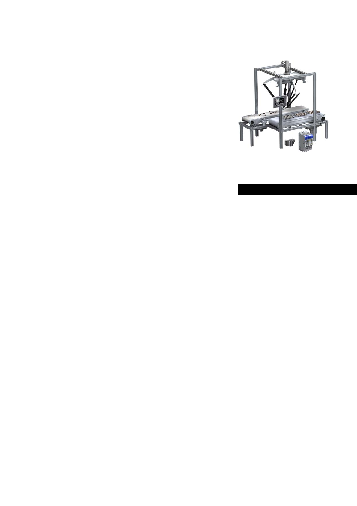
3 Controller-based Automation: Central motion control
The Lenze automation system "Controller-based Automation" serves to create complex automation
solutions with central motion control. Here, the controller is the control centre of the system.
System structure of the Controller-based Automation: "All from one single source"
[3-1] Example configuration (EtherCAT bus system): 3200 C controller with I/O system 1000 and i700 servo inverter
Lenze · Controller-based Automation - Visualisation · System Manual · DMS 1.5 EN · 04/2014 · TD17 13
Page 14

3 Controller-based Automation: Central motion control
_ _ _ _ _ _ _ _ _ _ _ _ _ _ _ _ _ _ _ _ _ _ _ _ _ _ _ _ _ _ _ _ _ _ _ _ _ _ _ _ _ _ _ _ _ _ _ _ _ _ _ _ _ _ _ _ _ _ _ _ _ _ _ _
Lenze provides especially coordinated system components:
• Engineering software
The Lenze Engineering tools on your Engineering PC (Windows® operating system) serve to
parameterise, configure, and diagnose the system. The Engineering PC communicates with the
controller via Ethernet.
•Controller
The Lenze controller is available as Panel Controller with integrated touch display and as
Cabinet Controller in control cabinet design.
Cabinet Controllers provide a direct coupling of the I/O system 100 via the integrated backplane
bus.
The Runtime software
These software versions are available:
• "Logic": Sequence control in the controller, motion control in the inverter
• "Motion": Sequence control and motion control in the controller, inverter as actuating drive
• "Visu": Optional visualisation of the automation system, can be used separately or in addition
to "Logic" or "Motion"
An external monitor panel/display can be connected to the Cabinet Controller 3231 C/
3241 C.
• Without software: Controller as single component with operating system only
•Bus systems
EtherCAT is a standard "on board" bus system of the Controller-based Automation. EtherCAT
enables the control of all nodes (Motion/Logic) on one common fieldbus.
Optionally, CANopen, PROFIBUS and PROFINET can be used as extended topologies.
The Controllers c300/p300 have a CANopen interface "on board" as well (in addition to
EtherCAT).
• Inverter (e.g. Servo Inverter i700)
( 20) provides the control and/or visualisation of motion sequences.
"Logic & Motion" runtime software
The "Controller-based Automation" system allows for the central control of devices for Logic and
Motion applications. The runtime software runs on the controller.
In case of Logic applications, the sequence control is carried out in the controller and the motion
control is carried out in the inverter.
In case of Motion applications , the sequence control and motion control are carried out in the
controller. The inverter is used as actuating drive.
• Motion applications make special demands on the cycle time and real-time capability of the bus
system between the controller and the subordinate fieldbus nodes.
• this is for instance the case if the field devices, for example, are to move in a synchronised way
or if position setpoints are to be transmitted.
14 Lenze · Controller-based Automation - Visualisation · System Manual · DMS 1.5 EN · 04/2014 · TD17
Page 15

4 System description
4.1 Visualisation system structure
_ _ _ _ _ _ _ _ _ _ _ _ _ _ _ _ _ _ _ _ _ _ _ _ _ _ _ _ _ _ _ _ _ _ _ _ _ _ _ _ _ _ _ _ _ _ _ _ _ _ _ _ _ _ _ _ _ _ _ _ _ _ _ _
4 System description
This chapter describes the use of an Industrial PC as a visualisation device and the required
components.
4.1 Visualisation system structure
The field of visualisation technology distinguishes between three system architectures. The system
structure describes where to find the control system, the visualisation application, and the operator
device in the system.
Depending on the application ...
• control, visualisation, and operation can be carried out from one common controller.
Integrated control system
• the system structure can be composed of different devices (optionally from different
manufacturers in each case).
Stand-alone application
Since the system architectures are independent of the communication between the »VisiWinNET®«
visualisation system and the field devices, they can be freely combined.
( 17)
( 16)
More information regarding the communication with field devices can be found here:
Field devices
( 26)
Lenze · Controller-based Automation - Visualisation · System Manual · DMS 1.5 EN · 04/2014 · TD17 15
Page 16
4 System description
4.1 Visualisation system structure
_ _ _ _ _ _ _ _ _ _ _ _ _ _ _ _ _ _ _ _ _ _ _ _ _ _ _ _ _ _ _ _ _ _ _ _ _ _ _ _ _ _ _ _ _ _ _ _ _ _ _ _ _ _ _ _ _ _ _ _ _ _ _ _
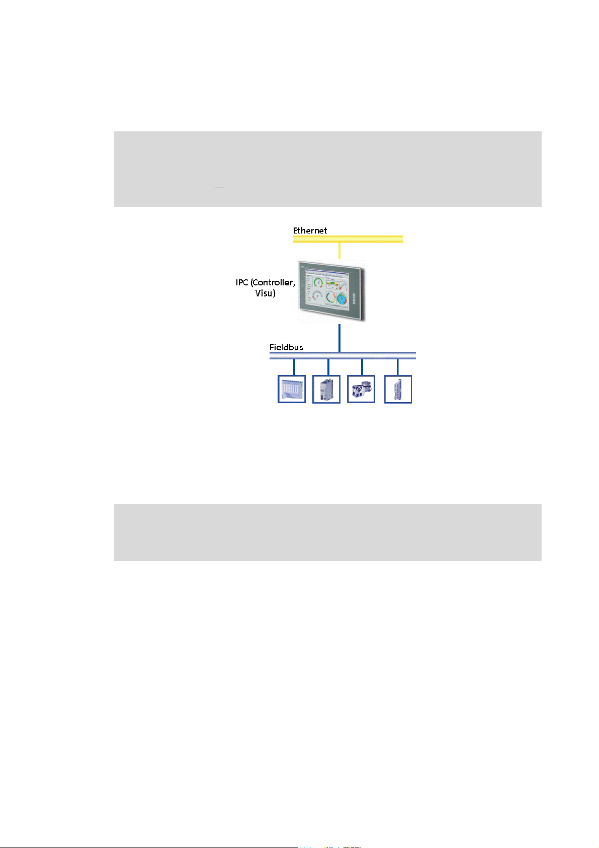
4.1.1 Stand-alone application
The control system (controller) and visualisation (Visu) run on separate controllers, respectively.
• The visualisation IPC (Visu IPC) directly communicates with an external control system and the
lower-level field devices. A fieldbus or a higher-level Ethernet network are used for
communication.
• The visualisation can access variables of the control system and (depending on the bus system)
in addition can directly access parameters of the field devices.
• For the visualisation, a Panel PC/Industrial PC Embedded Line or a control cabinet PC with an
external monitor panel can be used.
16
Lenze · Controller-based Automation - Visualisation · System Manual · DMS 1.5 EN · 04/2014 · TD17
Page 17
4 System description
4.1 Visualisation system structure
_ _ _ _ _ _ _ _ _ _ _ _ _ _ _ _ _ _ _ _ _ _ _ _ _ _ _ _ _ _ _ _ _ _ _ _ _ _ _ _ _ _ _ _ _ _ _ _ _ _ _ _ _ _ _ _ _ _ _ _ _ _ _ _
4.1.2 Integrated control system
Note!
The integrated control system is only provided for IPCs/controllers with an integrated
monitor panel or
display.
for IPCs/controllers with a DVI interface for an external monitor panel/
The control system (Logic/Motion) and the visualisation run on the same IPC (controller, Visu).
The visualisation (Visu) ...
• is directly coupled to the control system (Logic/Motion);
• can access variables of the control system and (depending on the bus system) in addition can
directly access the parameters of the field devices.
"Controller-based Automation" system manual
Here you'll find more information relating to the visualisation as part of a control
system.
Lenze · Controller-based Automation - Visualisation · System Manual · DMS 1.5 EN · 04/2014 · TD17 17
Page 18
4 System description
4.1 Visualisation system structure
_ _ _ _ _ _ _ _ _ _ _ _ _ _ _ _ _ _ _ _ _ _ _ _ _ _ _ _ _ _ _ _ _ _ _ _ _ _ _ _ _ _ _ _ _ _ _ _ _ _ _ _ _ _ _ _ _ _ _ _ _ _ _ _
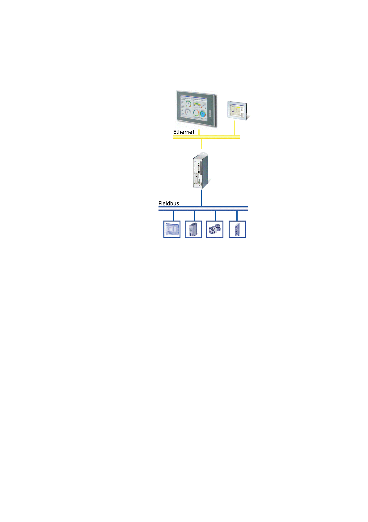
4.1.3 Client/server system
The client/server system is a classical SCADA application (Supervisory Control and Data Acquisition).
• A central server, IPC (controller) for data management (alarm, recipe, trend management) is
typical of this application.
• Operation and monitoring of the machine/system can be carried out via an optional number of
client devices.
18
Lenze · Controller-based Automation - Visualisation · System Manual · DMS 1.5 EN · 04/2014 · TD17
Page 19

4 System description
4.2 System components
_ _ _ _ _ _ _ _ _ _ _ _ _ _ _ _ _ _ _ _ _ _ _ _ _ _ _ _ _ _ _ _ _ _ _ _ _ _ _ _ _ _ _ _ _ _ _ _ _ _ _ _ _ _ _ _ _ _ _ _ _ _ _ _
4.2 System components
4.2.1 Controller: "Controller-based Automation" (control technology version 3.x)
Lenze offers a range of different controllers in cabinet and panel design. Depending on the
application, the controllers are provided with different processors, panel sizes, and runtime modes.
More information about Lenze controllers in the "Controller-based Automation" system
can be found in the following sets of documentation:
• "Controller-based Automation" system manual
• Controller reference manual
4.2.2 Industrial PCs (IPC): "PC-based Automation" (control technology version 2.x)
The platform strategy of the Lenze Industrial PCs provides for individual system concepts with
regard to the power, display size, and function, producing various designs from which you can select
the platform for your automation solution customised for each case.
This universal and scalable IPC platform is complemented by HMIs which are provided in fixed
configurations and can also fulfil automation functions in a restricted way.
More information about Lenze Industrial PCs in the "PC-based Automation" system can
be found in the following sets of documentation:
• "PC-based Automation" system manual
• Industrial PC (IPC) software manual
Lenze · Controller-based Automation - Visualisation · System Manual · DMS 1.5 EN · 04/2014 · TD17 19
Page 20

4 System description
4.2 System components
_ _ _ _ _ _ _ _ _ _ _ _ _ _ _ _ _ _ _ _ _ _ _ _ _ _ _ _ _ _ _ _ _ _ _ _ _ _ _ _ _ _ _ _ _ _ _ _ _ _ _ _ _ _ _ _ _ _ _ _ _ _ _ _
4.2.3 Runtime software
The Industrial PC is the core of the visualisation system. To perform the tasks required, the Industrial
PC requires the so-called "runtime software".
The runtime software for instance comprises the operating system (Windows® CE). Moreover,
further software components are required which, for example, execute the control tasks of the IPC
or the visualisation application of the different applications.
These software versions are available:
• "Logic": Sequence control in the controller, motion control in the inverter
• "Motion": Sequence control and motion control in the controller, inverter as actuating drive
• "Visu": visualisation of the automation system, can be used separately or in addition to "Logic"
or "Motion"
An external monitor panel/display can be connected to the Cabinet Controller 3231 C/3241 C.
• Without software: controller as single component with operating system only
The runtime software and the licence required for using the software are usually ordered together
with the Industrial PC.
4.2.3.1 "Logic" and "Motion" runtime software
Logic Motion
The controller controls...
• simple motion sequences;
• by logically
Logic applications are suitable for the control of inverters
without
• execute simple motion sequences;
• can only be controlled via PLC functionality.
combined control signals.
a Motion functionality which ...
"Controller-based Automation" system manual
Here you'll find more information relating to the "Logic" and "Motion" runtime software.
The controller controls extensive motion sequences.
The runtime software "Motion" ...
• contains the PLCopen library;
• contains the "Logic" mode;
• supports "SoftMotion".
Motion applications are suitable...
• for the control of inverters executing complex motion
sequences of multi-axes in several dimensions;
• ...for the control of devices that are to traverse
synchronously;
• for the transfer of setpoints.
20
Lenze · Controller-based Automation - Visualisation · System Manual · DMS 1.5 EN · 04/2014 · TD17
Page 21

4 System description
4.2 System components
_ _ _ _ _ _ _ _ _ _ _ _ _ _ _ _ _ _ _ _ _ _ _ _ _ _ _ _ _ _ _ _ _ _ _ _ _ _ _ _ _ _ _ _ _ _ _ _ _ _ _ _ _ _ _ _ _ _ _ _ _ _ _ _
4.2.3.2 "Visu" runtime software
All visualisation applications are executed within a runtime
environment (runtime). The licence required for this purpose
depends on the hardware operating system.
The "Visu" runtime software is not pre-installed on the Lenze Industrial PCs, but is loaded to the IPC
together with the visualisation application. By means of »VisiWinNET®«, the program parts
required are automatically compiled.
If you use the »VisiWinNET®« compact runtime software, the download is carried out directly from
»VisiWinNET®«. In the case of the other runtime variants, »VisiWinNET®« creates a setup file which,
apart from the actual runtime software, also contains the complete visualisation application, which
must be installed on the respective target system.
Depending on the target system/operating system which is to be used for the visualisation process,
various versions of the runtime software with different functional ranges are provided.
Lenze · Controller-based Automation - Visualisation · System Manual · DMS 1.5 EN · 04/2014 · TD17 21
Page 22

4 System description
4.2 System components
_ _ _ _ _ _ _ _ _ _ _ _ _ _ _ _ _ _ _ _ _ _ _ _ _ _ _ _ _ _ _ _ _ _ _ _ _ _ _ _ _ _ _ _ _ _ _ _ _ _ _ _ _ _ _ _ _ _ _ _ _ _ _ _
»VisiWinNET®« Compact CE
This runtime system for Windows® CE systems only requires a small amount of memory space and
is specially designed for systems with a lower processor power. Typical scopes of application are the
machine-oriented operation and monitoring with low demands with regard to the visualisation.
They are used in stand-alone applications and integrated control systems.
The following Lenze devices can be used:
•Controller:
• Panel Controller p300/p500
• Cabinet Controller 3231 C/3241 C (with an external monitor panel/display)
• Industrial PCs:
• Embedded Line EL 1800 - 9800
• Command Station CS 5800 - 9800
• Control cabinet PC CPC 2800
•HMIs:
•EL 100
• EL 100 PLC
»VisiWinNET®« Compact XP
This runtime system for Windows® XP Embedded systems only requires a small amount of memory
space and is specially designed for systems with a lower processor power. Typical scopes of
application are the machine-oriented operation and monitoring on Industrial PCs, where
customised applications run alongside with the visualisation software. They are used in stand-alone
applications.
The following Lenze devices can be used:
• Cabinet Controller 3241 C (with an external monitor panel/display)
• Industrial PCs:
• Embedded Line EL 1800 - 9800
• Command Station CS 5800 - 9800
• Control cabinet PC CPC 2800
»VisiWinNET®« Standard XP
This runtime system for Windows® XP or Windows® XP Embedded is designed for a medium to high
performance class. It is used in stand-alone applications.
The following Lenze devices can be used:
• Cabinet Controller 3241 C (with an external monitor panel/display)
• Industrial PCs:
• Embedded Line EL 1800 - 9800
• Command Station CS 5800 - 9800
• Control cabinet PC CPC 2800
22
Lenze · Controller-based Automation - Visualisation · System Manual · DMS 1.5 EN · 04/2014 · TD17
Page 23

4 System description
4.2 System components
_ _ _ _ _ _ _ _ _ _ _ _ _ _ _ _ _ _ _ _ _ _ _ _ _ _ _ _ _ _ _ _ _ _ _ _ _ _ _ _ _ _ _ _ _ _ _ _ _ _ _ _ _ _ _ _ _ _ _ _ _ _ _ _
»VisiWinNET®« Standard Client/Server (C/S)
This runtime system for Windows® XP as client/server system offers the whole functional range of
the »VisiWinNET®« standard. However, all information used commonly is managed centrally on one
server.
So-called "Terminal Clients" serve as clients. They are simple Industrial PCs and HMIs under
Windows® CE or Windows® XP without a special runtime software, to which only the visualisation
application must be imported.
As an alternative, "Thin Clients" can also be used, which do not require any further installation, since
the application completely runs in the server in this case.
The following Lenze devices are suitable for the use as server:
• Industrial PCs:
• Embedded Line EL 1800 - 9800
• Command Station CS 5800 - 9800
• Cabinet Controller 3231 C/3241 C (with an external monitor panel/display)
The following Lenze devices are suitable for the use as client:
•Controller:
• Panel Controller p300/p500
• Cabinet Controller 3231 C/3241 C (with an external monitor panel/display)
• Industrial PCs:
• Embedded Line EL 1800 - 9800
• Command Station CS 5800 - 9800
• Control cabinet PC CPC 2800
•HMIs:
•EL 100
• EL 100 PLC
• Thin clients:
• Embedded Line EL 1800 - 9800 TC
• Command Station CS 5800 - 9800 TC
Lenze · Controller-based Automation - Visualisation · System Manual · DMS 1.5 EN · 04/2014 · TD17 23
Page 24

4 System description
4.2 System components
_ _ _ _ _ _ _ _ _ _ _ _ _ _ _ _ _ _ _ _ _ _ _ _ _ _ _ _ _ _ _ _ _ _ _ _ _ _ _ _ _ _ _ _ _ _ _ _ _ _ _ _ _ _ _ _ _ _ _ _ _ _ _ _
Functional range of the runtime software variants
Application Easy operation &
Target system Windows® CE Windows® XP
Runtime version Compact CE Compact XP Standard XP Standard XP / CS
Client / server Only client - -
Development system(s) »VisiWinNET®« Smart / Professional »VisiWinNET®«
Microsoft® Visual Studio .NET
Required
Use of Word, Excel, and Outlook -
Printing Only PCL printers
History / archive / trend Online history
Alarm history
Logging Restricted Restricted
Number of pages Depending on
Object per image Depending on
System is OPC server - -
Connection via OPC
Connection via driver Yes (only
Number of process variables Max. 2000 Max. 2000 Unlimited Unlimited
Logic Under »VisiWinNET®« Smart restricted
Recipes XML XML XML / MDB XML / MDB
Colour gradients - Option Option Option
Transparent objects - Option Option Option
FDA Restricted Restricted
Database handling Only if application has been developed with
: Function available
-: Function not available
monitoring
under Windows®
CE
(depending on
the memory
capacity)
the memory
capacity
the memory
capacity
»VisiWinNET®«
drivers)
With »VisiWinNET®« Professional, individual system
Operation &
monitoring
under Windows®
XP
Embedded
Only for »VisiWinNET®« Professional
Online history
(depending on
the memory
capacity)
Depending on
the memory
capacity
Depending on
the memory
capacity
Yes (only
»VisiWinNET®«
drivers)
extensions can be integrated.
»VisiWinNET®« Professional.
Visualisation
under
Windows® XP for
complex machine
operation
Windows® XP Windows® XP or
Online history Online history
Client/server
applications for
control room
solutions
Windows® Server
2003
Professional
Unlimited Unlimited
Unlimited Unlimited
24
"Controller-based Automation" system manual
Here you'll find more information relating to the visualisation as part of a control
system.
Lenze · Controller-based Automation - Visualisation · System Manual · DMS 1.5 EN · 04/2014 · TD17
Page 25

4 System description
4.2 System components
_ _ _ _ _ _ _ _ _ _ _ _ _ _ _ _ _ _ _ _ _ _ _ _ _ _ _ _ _ _ _ _ _ _ _ _ _ _ _ _ _ _ _ _ _ _ _ _ _ _ _ _ _ _ _ _ _ _ _ _ _ _ _ _
4.2.3.3 "Visu" runtime software - licence information
A licence is required for executing the "Visu" runtime software.
The licence information indicates which runtime software version
(Compact, Standard, etc.) may be used, how many clients are
allowed to log on to a client/server system, and how many
variables (power tags) can be displayed via the visualisation.
Depending on the device type, the licence information is stored in different ways.
•Controller:
• Panel Controller p300/p500
• Cabinet Controller 3231 C/3241 C (with an external monitor panel/display)
• Industrial PCs:
• Embedded Line EL 1800 - 9800
• Command Station CS 5800 - 9800
• Control cabinet PC CPC 2800
Under Windows® XP, the licence information can optionally be provided via a "Dongle" for the USB
interface or via a licence file that is connected to the MAC address of the network interface card. The
licence file is used by default.
Under Windows® CE, solely the use of the licence file is possible. The licence desired is specified with
the order, so that the device can be delivered in a fully configured state.
The EL 100 and EL 100 PLC HMIs are provided with a Visu licence by default (»VisiWinNET®« compact
CE with a fixed number of power tags). This makes a separate dongle/separate licence file
dispensable.
Lenze · Controller-based Automation - Visualisation · System Manual · DMS 1.5 EN · 04/2014 · TD17 25
Page 26

4 System description
4.2 System components
_ _ _ _ _ _ _ _ _ _ _ _ _ _ _ _ _ _ _ _ _ _ _ _ _ _ _ _ _ _ _ _ _ _ _ _ _ _ _ _ _ _ _ _ _ _ _ _ _ _ _ _ _ _ _ _ _ _ _ _ _ _ _ _
4.2.4 Field devices
The following field devices are supported:
•Inverter:
• i700 servo inverter
• Inverter Drives 8400 / 8400 motec / 8400 protec
• Servo Drives 9400 Highline
• ECS servo system
• 8200 vector frequency inverter
• 9300 servo inverters
• Further field devices:
• I/O system 1000
• I/O system IP20 compact/modular
• Other devices for which an applicable device description file is available.
• Control systems:
• Logic & Motion
• Siemens Simatic® S7 300/400
•VIPA
•SAIA
• Other control systems for which an OPC server or a »VisiWinNET®« direct driver is available.
Basically, two different scenarios with external control systems must be distinguished for the data
to be visualised. This may lead to restricted access possibilities.
More information relating to the system structure and the control system (Logic &
Motion) can be found in the following sets of documentation:
• "PC-based Automation" system manual (control technology V2.x)
• "Controller-based Automation" system manual (control technology V3.x)
26
Lenze · Controller-based Automation - Visualisation · System Manual · DMS 1.5 EN · 04/2014 · TD17
Page 27

4 System description
4.2 System components
_ _ _ _ _ _ _ _ _ _ _ _ _ _ _ _ _ _ _ _ _ _ _ _ _ _ _ _ _ _ _ _ _ _ _ _ _ _ _ _ _ _ _ _ _ _ _ _ _ _ _ _ _ _ _ _ _ _ _ _ _ _ _ _
4.2.4.1 Direct access to the field devices
• The controller and the IPC (Visu) access the fieldbus independently of each other.
• The visualisation (Visu) can access the parameters of the field devices and the parameters of the
controller.
Note!
• Direct access to the field devices connected to the fieldbus ensures a maximum
independence of the two systems, but is rarely reasonable in practical operation.
• The configuration with independent control and visualisation systems is only
recommended for systems without
• Depending on the bus system used, several bus masters that are independent of each other can
be used.
• The visualisation may impact the real-time capability of the bus. Therefore this configuration is
only suitable for Motion systems to a limited extent. (It also depends on the bus system used)
Direct access to field devices is possible for the following bus systems:
•CANopen
Details regarding the suitability of the respective field devices can be found here:
Network topologies
( 32)
a Lenze control system!
Lenze · Controller-based Automation - Visualisation · System Manual · DMS 1.5 EN · 04/2014 · TD17 27
Page 28

4 System description
4.2 System components
_ _ _ _ _ _ _ _ _ _ _ _ _ _ _ _ _ _ _ _ _ _ _ _ _ _ _ _ _ _ _ _ _ _ _ _ _ _ _ _ _ _ _ _ _ _ _ _ _ _ _ _ _ _ _ _ _ _ _ _ _ _ _ _
4.2.4.2 Access to the control system and the field devices connected
• When using the Lenze control technology, the visualisation can directly access the field devices
without any further impact, using the Industrial PC as gateway. When different control systems
are used, this is usually not possible. Therefore it is recommended to only use data of the
controller.
• To display field device data in the visualisation, the controller must import these data cyclically
and transfer them to a transfer section (e.g. a data block) which is only accessed by the
visualisation. This ensures field device data access without any further effects.
28
Lenze · Controller-based Automation - Visualisation · System Manual · DMS 1.5 EN · 04/2014 · TD17
Page 29

4 System description
4.2 System components
_ _ _ _ _ _ _ _ _ _ _ _ _ _ _ _ _ _ _ _ _ _ _ _ _ _ _ _ _ _ _ _ _ _ _ _ _ _ _ _ _ _ _ _ _ _ _ _ _ _ _ _ _ _ _ _ _ _ _ _ _ _ _ _
4.2.5 Engineering tool»VisiWinNET®«
With »VisiWinNET®«, Lenze provides a scalable Engineering tool to create visualisation applications
according to individual requirements and load them on the Industrial PCs.
»VisiWinNET®« is provided in the versions »VisiWinNET®« Smart and »VisiWinNET®« Professional.
4.2.5.1 »VisiWinNET®« Smart
For easy interface creation, »VisiWinNET®« Smart provides a user-friendly visualisation system. It
can be used as a flexible tool for the creation of simple applications or for service purposes.
»VisiWinNET®« Smart is provided with an individual full-graphics integrated development
environment and supports the user by ready-made templates. One of the system's strong points is
the possibility of combining it with »VisiWinNET®« Professional.
Functions
Suitable for machine-oriented applications.
Lenze · Controller-based Automation - Visualisation · System Manual · DMS 1.5 EN · 04/2014 · TD17 29
Page 30

4 System description
4.2 System components
_ _ _ _ _ _ _ _ _ _ _ _ _ _ _ _ _ _ _ _ _ _ _ _ _ _ _ _ _ _ _ _ _ _ _ _ _ _ _ _ _ _ _ _ _ _ _ _ _ _ _ _ _ _ _ _ _ _ _ _ _ _ _ _
4.2.5.2 »VisiWinNET®« Professional
»VisiWinNET®« Professional is completely integrated into the Microsoft® Visual Studio .NET
integrated development environment and provides the basis for the creation of visualisation and
SCADA applications with a high functionality.
The ready-made templates and modules can be used to smoothly create applications via "drag and
drop". If required, the system permits individual program-related changes on the basis of Visual
Basic .NET and C#. This serves to solve company-specific and complex tasks when the standard
visualisation functions are not sufficient.
Functions
• For complex applications
• For client/server systems with SCADA applications
• For individual and company-related programming
• For the connection to databases or other Microsoft® Office programs
• For the use of complex report functions
• For establishing an individual visualisation kit
4.2.5.3 Visualisation kit
The .NET functions and object-oriented programming enable the creation of individual control
elements and machine modules. Using ready-made modules, individual visualisation kits can be
implemented according to your personal requirements. In both systems, applications, except for
scripts, can be edited reciprocally.
The easy handling of »VisiWinNET®« Smart and the openness of the more complex »VisiWinNET®«
Professional provide substantial advantages when projects are edited reciprocally.
Note!
30
»VisiWinNET®« Professional is an expert system that requires special program
knowledge and goes far beyond the creation of a drag-and-drop system.
»VisiWinNET®«This is why Professional is not available as a pure catalog product.
Lenze · Controller-based Automation - Visualisation · System Manual · DMS 1.5 EN · 04/2014 · TD17
Page 31

4 System description
4.2 System components
_ _ _ _ _ _ _ _ _ _ _ _ _ _ _ _ _ _ _ _ _ _ _ _ _ _ _ _ _ _ _ _ _ _ _ _ _ _ _ _ _ _ _ _ _ _ _ _ _ _ _ _ _ _ _ _ _ _ _ _ _ _ _ _
4.2.6 Backup of visualisation data (UPS functionality)
The Controllers 3221 C/3231 C back up the visualisation data cyclically every 60 seconds. The
visualisation data backed up are therefore not exactly up-to-date after a voltage failure. Depending
on the time at which the voltage failure occurs, the data status backed up may be out-of-date for up
to 59 seconds (the interval between two backup processes is 60 seconds).
When a voltage failure occurs, the Controllers 3241 C back up the visualisation data on the SD card
in an exactly isochronous fashion if a capacitor pack (CAPS-PACK) is connected.
The Controllers p300/p500 are equipped with implemented UPS for the buffering of visualisation
data.
The EL 100 and EL 100 PLC HMIs are provided with an internal capacitor for buffering the current
supply. Like this, remanent PLC variables can be saved with mains failure protection.
Operating instructions for controllers / Industrial PCs / HMI
Here, further information can be found.
4.2.6.1 Capacitor pack (CAPS-PACK)
The capacitor pack serves to buffer the current supply of the controller/IPC for some seconds. Like
this, current fluctuations can be compensated.
In the case of a power failure, the capacitors ensure the current supply. Within this protected time,
specially marked variable contents (remanent PLC variables) can be saved.
The following controllers and Industrial PCs can be equipped with a capacitor pack (CAPS-PACK) for
backup:
• Controller 3241 C
• EL 1800 - 9800
• CS 5800 - 9800
• CPC 2800
4.2.6.2 Battery pack (ACCU-PACK)
The battery pack serves to bridge longer power failures. Within this protected time, further data
from the visualisation can be saved (in addition to the remanent PLC variables).
Alarms, batch protocols, trends, or recipe data can be saved. If this data has been defined as
remanent memory data it will be written to the memory card via a cache of a variable size.
If a power failure occurs, the battery pack activates an alarm and all data in the cache will be saved.
When the system is restarted, the data saved with mains failure protection will still be available.
The following controllers and Industrial PCs can be equipped with a battery pack (ACCU-PACK) for
backup:
• Controller 3241 C
• EL 1800 - 9800
• CS 5800 - 9800
• CPC 2800
Lenze · Controller-based Automation - Visualisation · System Manual · DMS 1.5 EN · 04/2014 · TD17 31
Page 32

4 System description
4.3 Network topologies
_ _ _ _ _ _ _ _ _ _ _ _ _ _ _ _ _ _ _ _ _ _ _ _ _ _ _ _ _ _ _ _ _ _ _ _ _ _ _ _ _ _ _ _ _ _ _ _ _ _ _ _ _ _ _ _ _ _ _ _ _ _ _ _
4.3 Network topologies
The Lenze visualisation system supports different control and bus systems connected via
»VisiWinNET®« channels. Depending on the control or bus system used, the communication and
network options are different.
Communication has an impact on the usability of the operating systems and device lines.
4.3.1 Channels
The following »VisiWinNET®« communication channel types are distinguished:
• »VisiWinNET®« driver (direct driver)
•OPC server
Note!
There is no OPC server available for PROFIBUS and PROFINET.
Controller p300:
• The OPC communication for »VisiWinNET« is exclusively available for Controller p300
without
• Otherwise, only the Lenze "Logic&Motion" direct driver can be used for the data
exchange between »VisiWinNET« and PLC.
PLC.
32
Depending on the bus system, there will be either a »VisiWinNET®« driver (direct driver) or an OPC
server available.
Lenze · Controller-based Automation - Visualisation · System Manual · DMS 1.5 EN · 04/2014 · TD17
Page 33

4 System description
4.3 Network topologies
_ _ _ _ _ _ _ _ _ _ _ _ _ _ _ _ _ _ _ _ _ _ _ _ _ _ _ _ _ _ _ _ _ _ _ _ _ _ _ _ _ _ _ _ _ _ _ _ _ _ _ _ _ _ _ _ _ _ _ _ _ _ _ _
Direct drivers... OPC servers...
• are contained in the scope of supply of the
»VisiWinNET®« development packages.
• are transferred from the Engineering PC to the
Industrial PC when the visualisation application is
downloaded.
• are specially tailored to »VisiWinNET®« and can only
be used for this software program.
• can be universally used and offer an open interface.
Like this, it is basically possible to integrate other
control or bus systems into »VisiWinNET®« if a
suitable OPC server is available.
• usually must be installed separately.
Stand-alone application
( 16)
Integrated control system ( 17)
Remote access
Remote access allows you to separate the control system and visualisation on physically separated
IPCs. The system structure is basically similar to a Client/server system
( 18).
• Remote access may be reasonable if a control system runs on a control cabinet PC, but no
monitor is available. In contrast to the client/server system, it is not possible to implement
several operator terminals.
• Depending on the fieldbus, direct drivers (optimised for remote access) or remote-capable OPC
servers can be used.
Channels
Lenze · Controller-based Automation - Visualisation · System Manual · DMS 1.5 EN · 04/2014 · TD17 33
( 32)
Page 34

4 System description
4.3 Network topologies
_ _ _ _ _ _ _ _ _ _ _ _ _ _ _ _ _ _ _ _ _ _ _ _ _ _ _ _ _ _ _ _ _ _ _ _ _ _ _ _ _ _ _ _ _ _ _ _ _ _ _ _ _ _ _ _ _ _ _ _ _ _ _ _
4.3.2 Browsing variables
For defining the variables to be displayed, »VisiWinNET®« allows you to "browse" variables.
Depending on the bus system and the control system type, there are different file formats available
from which »VisiWinNET®« can take the variable information and offer it for selection.
• In the case of CANopen, this is for instance an EDS file containing the parameters of the
corresponding device.
• This can also be the project file of a control program (e.g. Logic & Motion, CoDeSys, STEP 7®
program), containing the variables of the control.
Tip!
The »VisiWinNET®« project wizard helps you to select the right browser.
Browsing online/offline
With an automation system that is already completely available, some browsers allow you to
browse the system from »VisiWinNET®« (online "browsing").
In practical operation, online "browsing" is rarely used because the system is often not yet complete
and still has to be commissioned.
As an alternative, offline browsing is possible, which requires special device description files that
contain the parameter information of a specific device type. Depending on the control and bus
system, these files differ from each other.
The following chapters describe the way of browsing and the file types that can be used.
34
Lenze · Controller-based Automation - Visualisation · System Manual · DMS 1.5 EN · 04/2014 · TD17
Page 35

4 System description
4.3 Network topologies
_ _ _ _ _ _ _ _ _ _ _ _ _ _ _ _ _ _ _ _ _ _ _ _ _ _ _ _ _ _ _ _ _ _ _ _ _ _ _ _ _ _ _ _ _ _ _ _ _ _ _ _ _ _ _ _ _ _ _ _ _ _ _ _
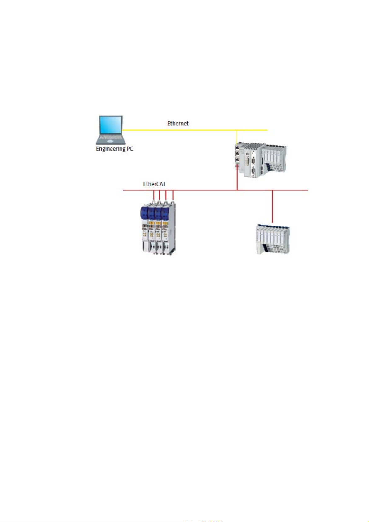
4.3.3 EtherCAT®
Note!
For Industrial PCs of the EL 1xx, EL x8xx, CS x8xx, and CPC x8xx series in control
technology release 2.5, the EtherCAT bus system is not
The EtherCAT bus system only allows one single master. Since the master functionality is typically
assigned to the control system, it is not possible that another controller accesses field devices
independently of the control system.
The Lenze controllers 3231 C/3241 C and p300/p500 are equipped with an "on board" EtherCAT
interface.
provided.
[4-1] Sample configuration: Controller 3200 C with EtherCAT
For more information on the use of EtherCAT®, please see the following sets of
documentation:
• "Controller-based Automation" system manual
• "Controller-based Automation - EtherCAT®" communication manual
Tip!
Lenze offers complete solutions for EtherCAT as part of the "Logic & Motion" control
technology.
Furthermore, »VisiWinNET®« can be used together with other EtherCAT control systems via
Ethernet if appropriate OPC servers or »VisiWinNET®« direct drivers are available.
Lenze · Controller-based Automation - Visualisation · System Manual · DMS 1.5 EN · 04/2014 · TD17 35
Page 36

4 System description
4.3 Network topologies
_ _ _ _ _ _ _ _ _ _ _ _ _ _ _ _ _ _ _ _ _ _ _ _ _ _ _ _ _ _ _ _ _ _ _ _ _ _ _ _ _ _ _ _ _ _ _ _ _ _ _ _ _ _ _ _ _ _ _ _ _ _ _ _
Available runtime software for Lenze controllers
Controller Runtime
Software
3231 C
3241 C
p300
p500
1) Available from »VisiWinNET®« version 6.4.
Windows®
Compact CE
Logic
Motion
Visu
Access Driver type Driver name Communication
Field devices OPC
PLC variables
(Logic & Motion)
IPC parameters OPC
OPC
Lenze.Digitec.OPCTunnel.DA )
Lenze.OPC_EtherCAT_CE
Lenze.Digitec.OPCTunnel.DA )
CoDeSys.OPC.DA )
Lenze.Digitec.OPCTunnel.DA )
type
EtherCAT OPC
Tunnel
EtherCAT OPC
Server
SoftPLC OPC
Tunnel
SoftPLC OPC
Server
Datamanager
OPC tunnel
Browser
Offline
(EDS/DCF/GDC 1))
Offline
(EDS/DCF/GDC 1))
Offline
(SYM)
Online/offline
(SYM)
Offline
(EDS/DCF)
36
Lenze · Controller-based Automation - Visualisation · System Manual · DMS 1.5 EN · 04/2014 · TD17
Page 37

4 System description
4.3 Network topologies
_ _ _ _ _ _ _ _ _ _ _ _ _ _ _ _ _ _ _ _ _ _ _ _ _ _ _ _ _ _ _ _ _ _ _ _ _ _ _ _ _ _ _ _ _ _ _ _ _ _ _ _ _ _ _ _ _ _ _ _ _ _ _ _
4.3.4 CANopen®
Note!
• Due to the access mechanisms of the CAN bus, the real-time capability of the bus may
be influenced by the visualisation if visualisation and control system communicate
independently of each other with the field devices via CAN. Therefore, this
constellation is only with restrictions suitable for the use in Motion systems.
This restriction does not apply to the Lenze Logic & Motion control system!
• As an alternative, it is recommended to access the variables of the field devices via
Ethernet and control system IPC.
Access to the control system and the field devices connected
Controller p300 ...
• are equipped with an integrated CAN communication interface (on board);
• only support the CAN master functionality
The optional MC-CAN2 communication card is not supported by controllers p300.
.
( 28)
Visualisation applications with CANopen are available for the following Lenze devices:
•HMI series EL 100
• Industrial PCs: EL 1800-9800, CS 5800-9800 and CPC 2800
The Industrial PCs use an OPC server for communication.
• Cabinet Controller 3231 C/3241 C (with an external monitor panel/display)
• Panel Controller p300/p500
Under Windows® CE, a direct driver is provided for communication.
Lenze · Controller-based Automation - Visualisation · System Manual · DMS 1.5 EN · 04/2014 · TD17 37
Page 38

4 System description
4.3 Network topologies
_ _ _ _ _ _ _ _ _ _ _ _ _ _ _ _ _ _ _ _ _ _ _ _ _ _ _ _ _ _ _ _ _ _ _ _ _ _ _ _ _ _ _ _ _ _ _ _ _ _ _ _ _ _ _ _ _ _ _ _ _ _ _ _
Functions
• Direct access to field devices via CANopen.
Access to the control system and the field devices connected
( 28)
• Control system access via CAN if the control systems have an SDO object directory.
• Control system access via Ethernet if an OPC server is available.
• SDO and PDO access (only with direct drivers).
• Visualisation variables can be imported from EDS/DCF/GDC files.
For more information regarding the use of CANopen®, please see the following sets of
documentation:
• "Controller-based Automation" system manual
• "Controller-based Automation - CANopen®" communication manual
Runtime software available for the corresponding device series
Hardware HMI Industrial PCs Controller
Device series EL 100
Example illustration
EL 100 PLC
Embedded
Line
EL 1800 -
9800
Command
Station
CS 5800 -
9800
Control
cabinet PC
CPC 2800 3231 C 3241 C p300 p500
Cabinet Controller Panel Controller
"Visu" runtime software
»VisiWinNET®«
Compact CE
»VisiWinNET®«
Compact XP
»VisiWinNET®«
Standard XP
»VisiWinNET®«
Standard
Client/server XP
Communication
CAN interface
(on board)
MC-CAN2
(optional)
: Function available
-: Function not available
1) For 3231 C/3241 C, only with external monitor panel/display at DVI interface.
2) Controllers p300 only support the CAN master functionality
- -
- -
- -
----- 2) -
- -
.
1) 1)
1) --
1) --
1) --
38
Lenze · Controller-based Automation - Visualisation · System Manual · DMS 1.5 EN · 04/2014 · TD17
Page 39

4 System description
4.3 Network topologies
_ _ _ _ _ _ _ _ _ _ _ _ _ _ _ _ _ _ _ _ _ _ _ _ _ _ _ _ _ _ _ _ _ _ _ _ _ _ _ _ _ _ _ _ _ _ _ _ _ _ _ _ _ _ _ _ _ _ _ _ _ _ _ _
Overview of the communication drivers and browsers available
Device series Runtime
Access Driver type Driver name Communication
Software
Controller
3231 C
3241 C
p300
p500
Windows® CE
Logic
Motion
Visu
Field devices OPC
PLC variables
OPC
(Logic & Motion)
Parameter of the
OPC
controller/IPC
EL 1800-9800
CS 5800-9800
CPC 2800
Windows® XP
Visu
Windows® CE
Field devices OPC
Field devices OPC
Logic
Motion
Visu
PLC variables
OPC
(Logic & Motion)
Parameter of the
OPC
controller/IPC
EL 100 Field devices Direct driver
EL 100 PLC Field devices Direct driver
PLC variables
Direct driver
(Logic & Motion)
1) Function is available from »VisiWinNET®« version 6.4!
Lenze.Digitec.OPCTunnel.DA
Lenze.OPC_CANbus_CE
Lenze.Digitec.OPCTunnel.DA
CoDeSys.OPC.DA
Lenze.Digitec.OPCTunnel.DA )
Lenze OPC system bus server
Lenze.Digitec.OPCTunnel.DA
Lenze.OPC_CANbus_CE
Lenze.Digitec.OPCTunnel.DA
CoDeSys.OPC.DA
Lenze.Digitec.OPCTunnel.DA )
Lenze CAN CE driver
Lenze CAN CE driver
Driver for CoDeSys runtimes
1)
1)
1)
1)
type
1)
CAN OPC tunnel Offline
CAN OPC server Offline
1)
SoftPLC OPC
Tunnel
SoftPLC OPC
Server
Datamanager
OPC tunnel
Lenze system bus
OPC server
1)
CAN OPC tunnel Offline
CAN OPC server Offline
1)
SoftPLC OPC
Tunnel
SoftPLC OPC
Server
Datamanager
OPC tunnel
»VisiWinNET®«
LenzeCAN Driver
»VisiWinNET®«
Lenze CAN Driver
»VisiWinNET®«
CoDeSys driver
Browser
(EDS/DCF/GDC 1))
(EDS/DCF/GDC 1))
Offline
(SYM)
Online/offline
(SYM)
Offline
(EDS/DCF)
Offline
(EDS/DCF/GDC1))
(EDS/DCF/GDC 1))
(EDS/DCF/GDC 1))
Offline
(SYM)
Online/offline
(SYM)
Offline
(EDS/DCF)
Offline
(EDS/DCF1)/GDC)
Offline
(EDS/DCF1)/GDC)
Offline
(SYM)
Lenze · Controller-based Automation - Visualisation · System Manual · DMS 1.5 EN · 04/2014 · TD17 39
Page 40

4 System description
4.3 Network topologies
_ _ _ _ _ _ _ _ _ _ _ _ _ _ _ _ _ _ _ _ _ _ _ _ _ _ _ _ _ _ _ _ _ _ _ _ _ _ _ _ _ _ _ _ _ _ _ _ _ _ _ _ _ _ _ _ _ _ _ _ _ _ _ _
4.3.5 PROFIBUS®
Visualisation applications with PROFIBUS are available for the following Lenze devices:
•HMI series EL 100
• Industrial PCs: EL 1800-9800, CS 5800-9800 and CPC 2800
The Industrial PCs use an OPC server for communication.
• Cabinet Controller 3231 C/3241 C (with an external monitor panel/display)
• Panel Controller p300/p500
Under Windows® CE, a direct driver is provided for communication.
The connection of the visualisation to PROFIBUS makes use of the properties that the MPI protocol
is "tunnelled" on PROFIBUS and the connection of an MPI node to PROFIBUS is identical as regards
the hardware. Thus a direct connection to a Siemens S7 control is possible without logging on a
separate PROFIBUS node in the control configuration.
For this purpose, the Industrial PCs are equipped with a communication card (MC-MPI), whereas the
interface is already available on-board for the EL 100 with the MPI variant.
To facilitate the creation of an application in »VisiWinNET®«, the variables can be imported from an
S7-PLC program. Communication drivers are available for all runtime systems.
Functions
• Access to Siemens S7-300/400 control systems via PROFIBUS (MPI)
• Access to other controls via Ethernet if an OPC server or »VisiWinNET®« direct driver is available.
• Visualisation variables can be imported from STEP 7®.
40
Lenze · Controller-based Automation - Visualisation · System Manual · DMS 1.5 EN · 04/2014 · TD17
Page 41

4 System description
4.3 Network topologies
_ _ _ _ _ _ _ _ _ _ _ _ _ _ _ _ _ _ _ _ _ _ _ _ _ _ _ _ _ _ _ _ _ _ _ _ _ _ _ _ _ _ _ _ _ _ _ _ _ _ _ _ _ _ _ _ _ _ _ _ _ _ _ _
Note!
The data of the connected PROFIBUS slaves cannot be directly accessed!
As an alternative, the control system can access variables of the field devices. The control
system automatically reads in the variables and provides them to the visualisation in a
transfer area.
Access to the control system and the field devices connected
( 28)
For more information regarding the use of PROFIBUS®, please see the following sets of
documentation:
• "Controller-based Automation" system manual
• "Controller-based Automation - PROFIBUS®" communication manual
Runtime software available for the corresponding device series
Hardware HMI Industrial PCs Controller
Embedded
Line
Device series EL 100
Example illustration
"Visu" runtime software
»VisiWinNET®«
Compact CE
»VisiWinNET®«
Compact XP
»VisiWinNET®«
Standard XP
»VisiWinNET®«
Standard
Client/server XP
Communication
MPI
(on board)
MC-MPI
(optional)
MC-PBM, master
(optional)
MC-PBS, slave
(optional)
: Function available
-: Function not available
1) For 3231 C/3241 C, only with external monitor panel/display at DVI interface.
EL 100 PLC
- -
- -
- -
----- -
- -
- -
- -
EL 1800 -
9800
Command
Station
CS 5800 -
9800
Control
cabinet PC
CPC 2800 3231 C 3241 C p300 p500
Cabinet Controller Panel Controller
1) 1)
1) --
1) --
1) --
Lenze · Controller-based Automation - Visualisation · System Manual · DMS 1.5 EN · 04/2014 · TD17 41
Page 42

4 System description
4.3 Network topologies
_ _ _ _ _ _ _ _ _ _ _ _ _ _ _ _ _ _ _ _ _ _ _ _ _ _ _ _ _ _ _ _ _ _ _ _ _ _ _ _ _ _ _ _ _ _ _ _ _ _ _ _ _ _ _ _ _ _ _ _ _ _ _ _
Overview of the communication drivers and browsers available
Device series Runtime
Software
Controller
3231 C
Windows® CE
Visu
3241 C
p300
p500
EL 100
EL 100 PLC
EL 1800-9800
CS 5800-9800
Windows® XP
Visu
CPC 2800
Windows® CE
Visu
Windows® CE
Logic
Motion
1) Function is available from »VisiWinNET®« version 6.4!
Access Driver type Driver name Communication
type
PLC variables
(external control)
Direct driver
Lenze MPI CE driver
»VisiWinNET®«
LenzeMPI Driver
(Basic datatypes
syntax /
Instruction list
AWL syntax)
PLC variables
(external control)
Direct driver
»VisiWinNET®« driver S7 for
Lenze MC MPI
»VisiWinNET®«
LenzeMPI Driver
(Basic datatypes
syntax /
Instruction list
AWL syntax)
PLC variables
(external control)
Direct driver
»VisiWinNET®« driver S7 for
Lenze MC MPI
»VisiWinNET®«
LenzeMPI Driver
(Basic datatypes
syntax /
Instruction list
AWL syntax))
PLC variables
(Logic & Motion)
OPC
Lenze.Digitec.OPCTunnel.DA
CoDeSys.OPC.DA
1)
1)
SoftPLC OPC
Tunnel
SoftPLC OPC
Server
IPC parameters OPC
Lenze.Digitec.OPCTunnel.DA )
Datamanager
OPC tunnel
Browser
Offline
(SDF, IL)
Offline
(SDF, IL)
Offline
(SDF, IL)
Offline
(SYM)
Online/offline
(SYM)
Offline
(EDS/DCF)
42
Lenze · Controller-based Automation - Visualisation · System Manual · DMS 1.5 EN · 04/2014 · TD17
Page 43

4 System description
4.3 Network topologies
_ _ _ _ _ _ _ _ _ _ _ _ _ _ _ _ _ _ _ _ _ _ _ _ _ _ _ _ _ _ _ _ _ _ _ _ _ _ _ _ _ _ _ _ _ _ _ _ _ _ _ _ _ _ _ _ _ _ _ _ _ _ _ _
4.3.6 PROFINET®
Visualisation applications with PROFINET are available for the following Lenze devices:
•HMI series EL 100
• Industrial PCs: EL 1800-9800, CS 5800-9800 and CPC 2800
The Industrial PCs use an OPC server for communication.
• Cabinet Controller 3231 C/3241 C (with an external monitor panel/display)
• Panel Controller p300/p500
[4-2] Basic structure of a visualisation system with PROFINET
Here, the PROFINET property is used, that each PROFINET switch allows for the connection of
standard Ethernet devices to PROFINET and real time on the bus is nevertheless ensured. This
provides the possibility of using the RFC1006 protocol (MPI via TCP/IP). The advantages of this
solution are that no special PROFINET interface is required and the visualisation does not need to be
logged on explicitly as PROFINET node in the control configuration.
The Lenze Industrial PCs, the controllers, and the EL100 HMI series are provided with an "on board"
Ethernet interface suitable for connection to a PROFINET switch.
To facilitate the creation of applications in »VisiWinNET®«, all variables can be imported from an S7PLC program. Communication drivers are available for all runtime systems.
Lenze · Controller-based Automation - Visualisation · System Manual · DMS 1.5 EN · 04/2014 · TD17 43
Page 44

4 System description
4.3 Network topologies
_ _ _ _ _ _ _ _ _ _ _ _ _ _ _ _ _ _ _ _ _ _ _ _ _ _ _ _ _ _ _ _ _ _ _ _ _ _ _ _ _ _ _ _ _ _ _ _ _ _ _ _ _ _ _ _ _ _ _ _ _ _ _ _
Functions
• Access to Siemens S7-300/400 control systems via PROFIBUS (MPI)
• Access to VIPA control systems via PROFINET (RFC1006)
• Visualisation variables can be imported from STEP7®
Note!
The data of the PROFINET field devices connected cannot be accessed directly! As an
alternative, the variables of the field devices should be accessed via the control system.
Access to the control system and the field devices connected
From the view of wiring, a PROFINET network is not a bus in the true sense, but a "switched"
Ethernet with point-to-point connections.
• This structure is described below. The real time data transfer runs via the connections printed in
violet.
• The connections printed in yellow are purely used for Ethernet data transfer. Data are also
transferred via PROFINET without real time interferences.
( 28)
For more information regarding the use of PROFINET®, please see the following sets of
documentation:
• "Controller-based Automation" system manual
• "Controller-based Automation - PROFINET®" communication manual
44
Lenze · Controller-based Automation - Visualisation · System Manual · DMS 1.5 EN · 04/2014 · TD17
Page 45

4 System description
4.3 Network topologies
_ _ _ _ _ _ _ _ _ _ _ _ _ _ _ _ _ _ _ _ _ _ _ _ _ _ _ _ _ _ _ _ _ _ _ _ _ _ _ _ _ _ _ _ _ _ _ _ _ _ _ _ _ _ _ _ _ _ _ _ _ _ _ _
Runtime software available for the corresponding device series
Hardware HMI Industrial PCs Controller
Embedded
Line
Device series EL 100
Example illustration
EL 100 PLC
EL 1800 -
9800
"Visu" runtime software
»VisiWinNET®«
Compact CE
»VisiWinNET®«
- -
Compact XP
»VisiWinNET®«
- -
Standard XP
»VisiWinNET®«
- -
Standard
Client/server XP
Communication
Ethernet interface
(on board)
MC-PND,
- -
I/O device
(optional)
: Function available
-: Function not available
1) For 3231 C/3241 C, only with external monitor panel/display at DVI interface.
Command
Station
CS 5800 -
9800
Control
cabinet PC
CPC 2800 3231 C 3241 C p300 p500
Cabinet Controller Panel Controller
1) 1)
1) --
1) --
1) --
Overview of the communication drivers and browsers available
Device series Runtime
Software
Controller
3231 C
3241 C
p300
p500
EL 100
EL 100 PLC
EL 1800-9800
CS 5800-9800
CPC 2800
Windows® CE
Visu
Windows® XP
Visu
Windows® CE
Visu
Access Driver type Driver name Communication
type
PLC variables
(external control)
Direct driver
»VisiWinNET®« driver for
Siemens S7 TCP/IP
»VisiWinNET®«
LenzeMPI Driver
(Basic datatypes
syntax /
Instruction list
AWL syntax)
PLC variables
(external control)
Direct driver
»VisiWinNET®« driver for
Siemens S7 TCP/IP
»VisiWinNET®«
LenzeMPI Driver
(Basic datatypes
syntax /
Instruction list
AWL syntax)
PLC variables
(external control)
Direct driver
»VisiWinNET®« driver for
Siemens S7 TCP/IP
»VisiWinNET®«
LenzeMPI Driver
(Basic datatypes
syntax /
Instruction list
AWL syntax))
Browser
Offline
(SDF, IL)
Offline
(SDF, IL)
Offline
(SDF, IL)
Lenze · Controller-based Automation - Visualisation · System Manual · DMS 1.5 EN · 04/2014 · TD17 45
Page 46

4 System description
4.3 Network topologies
_ _ _ _ _ _ _ _ _ _ _ _ _ _ _ _ _ _ _ _ _ _ _ _ _ _ _ _ _ _ _ _ _ _ _ _ _ _ _ _ _ _ _ _ _ _ _ _ _ _ _ _ _ _ _ _ _ _ _ _ _ _ _ _
4.3.7 Ethernet
Most control systems are equipped with an integrated Ethernet connection. Since Ethernet is much
more powerful than most fieldbuses, it is recommended to access the control system via Ethernet
(and not via the lower-level fieldbus system).
This option has been described in the previous bus-specific chapters. There is no general possibility
of accessing optional field devices via Ethernet because Ethernet only describes the physical bus
features, but not the transmission protocol. Depending on the field device to be addressed, different
Ethernet protocols are required.
Lenze supports the RFC1006 Ethernet protocol which is based on TCP/IP and is supported by many
control system manufacturers. Control systems by the following manufacturers can be accessed via
RFC1006:
• Siemens S7-300/400
•VIPA
•SAIA
In addition, drivers for access to the following control systems are available:
• Industrial PCs (PC-based Automation): 3S Smart Software Solutions (CoDeSys V2.x)
• Controller (Controller-based Automation): 3S Smart Software Solutions (CoDeSys V3.x)
46
Lenze · Controller-based Automation - Visualisation · System Manual · DMS 1.5 EN · 04/2014 · TD17
Page 47

4 System description
4.3 Network topologies
_ _ _ _ _ _ _ _ _ _ _ _ _ _ _ _ _ _ _ _ _ _ _ _ _ _ _ _ _ _ _ _ _ _ _ _ _ _ _ _ _ _ _ _ _ _ _ _ _ _ _ _ _ _ _ _ _ _ _ _ _ _ _ _
Runtime software available for the corresponding device series
Hardware HMI Industrial PCs Controller
Embedded
Line
Device series EL 100
Example illustration
EL 100 PLC
EL 1800 -
9800
"Visu" runtime software
»VisiWinNET®«
Compact CE
»VisiWinNET®«
- -
Compact XP
»VisiWinNET®«
- -
Standard XP
»VisiWinNET®«
- -
Standard
Client/server XP
Communication
Ethernet interface
(on board)
: Function available
-: Function not available
1) For 3231 C/3241 C, only with external monitor panel/display at DVI interface.
Command
Station
CS 5800 -
9800
Control
cabinet PC
CPC 2800 3231 C 3241 C p300 p500
Cabinet Controller Panel Controller
1) 1)
1) --
1) --
1) --
Lenze · Controller-based Automation - Visualisation · System Manual · DMS 1.5 EN · 04/2014 · TD17 47
Page 48

4 System description
4.3 Network topologies
_ _ _ _ _ _ _ _ _ _ _ _ _ _ _ _ _ _ _ _ _ _ _ _ _ _ _ _ _ _ _ _ _ _ _ _ _ _ _ _ _ _ _ _ _ _ _ _ _ _ _ _ _ _ _ _ _ _ _ _ _ _ _ _
Overview of the communication drivers and browsers available
Device series Runtime
Software
Controller
3231 C
Windows® CE
Visu
3241 C
p300
p500
EL 100
EL 100 PLC
EL 1800-9800
CS 5800-9800
Windows® XP
Visu
CPC 2800
Windows® CE
Visu
1) Function is available from »VisiWinNET®« version 6.4!
Access Driver type Driver name Communication
type
PLC variables
(external control)
Direct driver
»VisiWinNET®« driver for
Siemens S7 TCP/IP
»VisiWinNET®«
LenzeMPI Driver
(Basic datatypes
syntax /
Instruction list
AWL syntax)
PLC variables
(external control)
Direct driver
»VisiWinNET®« driver for
Siemens S7 TCP/IP
»VisiWinNET®«
LenzeMPI Driver
(Basic datatypes
syntax /
Instruction list
AWL syntax)
PLC variables
(external control)
Direct driver
»VisiWinNET®« driver for
Siemens S7 TCP/IP
»VisiWinNET®«
LenzeMPI Driver
(Basic datatypes
syntax /
Instruction list
AWL syntax))
PLC variables
(CoDeSys)
PLC variables
(Logic & Motion)
OPC
OPC
OPC
CoDeSys.OPC.DA )
Lenze.Digitec.OPCTunnel.DA
CoDeSys.OPC.DA
1)
SoftPLC OPC
Server
1)
SoftPLC OPC
Tunnel
SoftPLC OPC
Server
Browser
Offline
(SDF, IL)
Offline
(SDF, IL)
Offline
(SDF, IL)
Offline
(SDF, IL)
Online/offline
(SYM)
Online/offline
(SYM)
48
Lenze · Controller-based Automation - Visualisation · System Manual · DMS 1.5 EN · 04/2014 · TD17
Page 49

4 System description
4.3 Network topologies
_ _ _ _ _ _ _ _ _ _ _ _ _ _ _ _ _ _ _ _ _ _ _ _ _ _ _ _ _ _ _ _ _ _ _ _ _ _ _ _ _ _ _ _ _ _ _ _ _ _ _ _ _ _ _ _ _ _ _ _ _ _ _ _
4.3.8 Further bus systems
In addition to access via own direct drivers, »VisiWinNET®« also allows you to access field devices
via standardised OPC servers. If a standardised OPC server is available, any devices can be integrated
in »VisiWinNET®«.
Note!
Lenze only ensures the correct system function for communication systems for which
Lenze offers corresponding drivers and OPC servers in »VisiWinNET®«.
Lenze accepts no system responsibility for drivers and OPC servers not originating from
Lenze!
Lenze · Controller-based Automation - Visualisation · System Manual · DMS 1.5 EN · 04/2014 · TD17 49
Page 50

5 Commissioning
_ _ _ _ _ _ _ _ _ _ _ _ _ _ _ _ _ _ _ _ _ _ _ _ _ _ _ _ _ _ _ _ _ _ _ _ _ _ _ _ _ _ _ _ _ _ _ _ _ _ _ _ _ _ _ _ _ _ _ _ _ _ _ _
5 Commissioning
For commissioning the visualisation system you need an Engineering PC. This can be a standard
laptop.
The programs required for configuring, parameterising, and commissioning the visualisation
system are installed on the Engineering PC.
Engineering tool»VisiWinNET®«
( 29)
[5-1] Example configuration with IPCs of the EL series
[5-2] Example configuration with 3200 C controllers (connected to each other via an internal switch)
The Engineering PC...
• is connected with the Industrial PC (IPC)/controller via Ethernet.
• is used to transfer the runtime software to the IPC/controller.
The Engineering PC is not required for operating the visualisation system. It can be used to configure
an optional number of Industrial PCs.
"»VisiWinNET®« - Getting started" software manual/online help
Here you'll find more information relating to the commissioning of an Industrial PC/
controller as visualisation device.
50 Lenze · Controller-based Automation - Visualisation · System Manual · DMS 1.5 EN · 04/2014 · TD17
Page 51

6 Remote maintenance and diagnostics
6.1 Remote maintenance with an external router
_ _ _ _ _ _ _ _ _ _ _ _ _ _ _ _ _ _ _ _ _ _ _ _ _ _ _ _ _ _ _ _ _ _ _ _ _ _ _ _ _ _ _ _ _ _ _ _ _ _ _ _ _ _ _ _ _ _ _ _ _ _ _ _
6 Remote maintenance and diagnostics
For a remote maintenance of a Controller, the standard mechanisms for remote maintenance of a
PC can be used.
The standard mechanisms ...
• are based on Ethernet protocol and the protocols used for Ethernet;
• can be used between the Engineering/remote maintenance PC (Remote PC) and the
corresponding Lenze controller, IPC, or HMI.
The Engineering PC and remote PC are either connected directly to each other, or via remote
connection.
The following access mechanisms to a Lenze controller, Industrial PC, or HMI can be used ...
• with direct connection between the PCs within a local network;
• with a remote connection.
6.1 Remote maintenance with an external router
Establishing a remote connection requires an external router which establishes the remote
connection between two network segments.
The router has to be configured separately and has to be connected to the Lenze controller, IPC, or
HMI by one of the following types of connection:
•DSL
•ISDN
•Analog (modem)
Remote maintenance via an external router for instance is advisable if remote maintenance is
required for several controllers, IPCs, or HMIs.
Lenze · Controller-based Automation - Visualisation · System Manual · DMS 1.5 EN · 04/2014 · TD17 51
Page 52

6 Remote maintenance and diagnostics
6.2 Remote maintenance with a separate remote PC
_ _ _ _ _ _ _ _ _ _ _ _ _ _ _ _ _ _ _ _ _ _ _ _ _ _ _ _ _ _ _ _ _ _ _ _ _ _ _ _ _ _ _ _ _ _ _ _ _ _ _ _ _ _ _ _ _ _ _ _ _ _ _ _
6.2 Remote maintenance with a separate remote PC
Note!
Setting a remote maintenance may endanger the IT safety!
• This is particularly relevant if the remote PC is connected to an Ethernet network.
• Contact your IT administrator to take the necessary safety measures.
[6-1] Sample configuration: Remote maintenance of a Controller 3200 C
• The Engineering PC accesses the separate remote PC via an internet connection.
• The remote PC is connected to the Lenze controller, IPC, or HMI via Ethernet.
• On the remote PC, the Lenze engineering tools (such as »EASY Starter«, »PLC Designer«) are
installed.
• The remote PC can be controlled from the Engineering PC via screen redirection.
»Virtual Network Computing (VNC)«: Redirecting screen contents/entries
The screen contents of the controller, IPC, or HMI are redirected to the remote PC. This makes it
possible to actuate the functions of the device, for instance the same programs as for the local
connection via Ethernet can be used.
A basic overview of the different dial-in programs can be found in the following section.
( 56)
52
Lenze · Controller-based Automation - Visualisation · System Manual · DMS 1.5 EN · 04/2014 · TD17
Page 53

6 Remote maintenance and diagnostics
6.3 Log-in on an IPC of the x800 device series (PC-based automation)
_ _ _ _ _ _ _ _ _ _ _ _ _ _ _ _ _ _ _ _ _ _ _ _ _ _ _ _ _ _ _ _ _ _ _ _ _ _ _ _ _ _ _ _ _ _ _ _ _ _ _ _ _ _ _ _ _ _ _ _ _ _ _ _
6.3 Log-in on an IPC of the x800 device series (PC-based automation)
An RAS server runs on the IPCs. A user can log-in via modem/ISDN card on this RAS server. If
someone dials-in from a remote maintenance PC via this medium, the IPC executes a password
check and then activates the connection.
Further information about the function and configuration of RAS servers can be found in
the following documentations:
• Industrial PC - Parameter setting & Configuration
• HMI EL 100 with Windows® CE - HMI for visualisation/with control technology
6.4 Computer access via Telnet
Telnet is a standard mechanism for experts to change system settings.
Telnet ...
• enables the access to the Controller data (example: Contents of the SD card);
• requires an existing local connection or remote connection.
Note!
Controller p300:
• These devices come with a deactivated Telnet in the Lenze standard setting.
• The function can be activated via the »WebConfig«. The activation of the function can
influence the real-time behaviour.
• After a restart of the Controller, the function is deactivated again.
Lenze · Controller-based Automation - Visualisation · System Manual · DMS 1.5 EN · 04/2014 · TD17 53
Page 54

6 Remote maintenance and diagnostics
6.5 File transfer via FTP
_ _ _ _ _ _ _ _ _ _ _ _ _ _ _ _ _ _ _ _ _ _ _ _ _ _ _ _ _ _ _ _ _ _ _ _ _ _ _ _ _ _ _ _ _ _ _ _ _ _ _ _ _ _ _ _ _ _ _ _ _ _ _ _
6.5 File transfer via FTP
The File Transfer Protocol (FTP) is a network protocol for the transfer of data within networks.
• FTP makes it possible to exchange files between the Lenze controller, IPC, or HMI and other PCs.
• The controller, IPC, or HMI data can be accessed via FTP connection.
• FTP requires an existing connection or a remote connection.
• In order to be able to transfer files with Windows® via FTP, the Windows® Explorer can be used
which comes with an integrated FTP support.
Note!
FTP must be used for system-diagnostic purposes only. Deleting or changing system files
causes malfunctions of the controller!
Controller p300:
• These devices come with a deactivated FTP in the Lenze standard setting.
• The function can be activated via the »WebConfig«. The activation of the function can
influence the real-time behaviour.
• After a restart of the Controller, the function is deactivated again.
Further information relating to the function and configuration of FTP and web server/
»WebConfig« can be found in the reference manual:
• Controller - Parameter setting & configuration
54
Lenze · Controller-based Automation - Visualisation · System Manual · DMS 1.5 EN · 04/2014 · TD17
Page 55

6 Remote maintenance and diagnostics
6.6 Web server/»WebConfig«
_ _ _ _ _ _ _ _ _ _ _ _ _ _ _ _ _ _ _ _ _ _ _ _ _ _ _ _ _ _ _ _ _ _ _ _ _ _ _ _ _ _ _ _ _ _ _ _ _ _ _ _ _ _ _ _ _ _ _ _ _ _ _ _
6.6 Web server/»WebConfig«
The Lenze controllers, IPCs, and HMIs are provided with an integrated web server. The web server
makes it possible to parameterise the devices via »WebConfig«.
• The controller, IPC, and HMI parameters can be displayed/altered via web browser.
• In order to parameterise a controller, IPC, or HMI in a web-based fashion, a remote connection
(via Ethernet by specifying the IP address) to the desired device has to be established.
Further information on how to redirect screen contents can be found in the following
documentation:
"HMI EL 1xx" device series:
• HMI EL 100 with Windows® CE - HMI for visualisation/with control technology
Controller 3200 C / p300 / p500 :
• Controller - Parameter setting & configuration
Lenze · Controller-based Automation - Visualisation · System Manual · DMS 1.5 EN · 04/2014 · TD17 55
Page 56

6 Remote maintenance and diagnostics
6.7 »Virtual Network Computing (VNC)«: Redirecting screen contents/entries
_ _ _ _ _ _ _ _ _ _ _ _ _ _ _ _ _ _ _ _ _ _ _ _ _ _ _ _ _ _ _ _ _ _ _ _ _ _ _ _ _ _ _ _ _ _ _ _ _ _ _ _ _ _ _ _ _ _ _ _ _ _ _ _
6.7 »Virtual Network Computing (VNC)«: Redirecting screen contents/entries
For remote maintenance of a Lenze controller, IPC, and HMI, the screen contents can be redirected
to the Engineering PC. This makes it possible to view all keyboard entries/mouse movements of the
local PC on the remote PC.
The remote PC can be operated as if you were directly in front of it. However, the quality of the
remote connection is very important, since the display speed of the screen content strongly depends
on it. A bad connection may render program operation using the mouse impossible since you can no
longer track the movements of the mouse pointer. In such cases, use the command line based
protocols like FTP and telnet, depending on the function to be executed.
• Screen content can be redirected via a local connection or a remote connection.
• The »Virtual Network Computing (VNC)« software is installed on the controllers, IPCs, and HMIs
by default.
Further information on how to redirect screen contents can be found in the following
documentation:
"HMI EL 1xx" device series:
• HMI EL 100 with Windows® CE - HMI for visualisation/with control technology
Controller 3200 C / p300 / p500 :
• Controller - Parameter setting & configuration
»Virtual Network Computing (VNC)«
»Virtual Network Computing (VNC)« is a software developed by Olivetti & Oracle Research
Laboratory (from 1999 AT&T), which shows the screen content of a remote computer (with the VNC
server software running) on a local computer (with the VNC viewer software running). The
keyboard/mouse movements of the local computer can be viewed on the remote computer.
Alternatively, a "read only" mode can be set, where local entries have no impact on the remote
computer.
VNC can be found under "Open source licence"; the source code is provided free of charge for
purposes of advancement. The VNC server is already installed by default on controllers 3231 C/
3241 C, p300/p500, the devices of the EL 100 HMI series, and Industrial PCs EL x800.
The Engineering PC requires the corresponding VNC viewer software. The VNC viewer software is
provided on the CD that is part of the scope of supply of the devices.
As an alternative, the VNC viewer software is available in the download area at www.lenze.com
.
56
Lenze · Controller-based Automation - Visualisation · System Manual · DMS 1.5 EN · 04/2014 · TD17
Page 57

7 Appendix
7.1 Information regarding the FDA conformance
_ _ _ _ _ _ _ _ _ _ _ _ _ _ _ _ _ _ _ _ _ _ _ _ _ _ _ _ _ _ _ _ _ _ _ _ _ _ _ _ _ _ _ _ _ _ _ _ _ _ _ _ _ _ _ _ _ _ _ _ _ _ _ _
7 Appendix
7.1 Information regarding the FDA conformance
»VisiWinNET®« can provide a visualisation that complies with FDA regulations 21 CFR part 11 of the
Food and Drug Administration. These regulations are applicable to machines exported into the U.S..
Industry therefore demands that the operating system and, in some cases, also the production
machines must contain data backup functions and functions protecting against the manipulation
of data.
A basic demand of the FDA is that electronic data shall be equivalent to paper data and that
electronic signatures shall have the same significance and unambiguousness as handwritten
signatures. The system should provide an easy but yet effective protection against manipulation,
although it is commonly known that electronic data and even paper data can almost always be
subsequently changed or deleted in the event of a criminal intent.
Using »VisiWinNET®«, completely FDA-compliant visualisation applications can be created by
means of the following functions:
•User management
• Recording of all parameter changes
• Start / stop recording
• Managing/changing passwords
• Saving encoded data in a database.
Lenze · Controller-based Automation - Visualisation · System Manual · DMS 1.5 EN · 04/2014 · TD17 57
Page 58

8 Glossary
_ _ _ _ _ _ _ _ _ _ _ _ _ _ _ _ _ _ _ _ _ _ _ _ _ _ _ _ _ _ _ _ _ _ _ _ _ _ _ _ _ _ _ _ _ _ _ _ _ _ _ _ _ _ _ _ _ _ _ _ _ _ _ _
8Glossary
A
Application Implementation of a concrete function (e.g. speed control) on an individual
Application Samples Predefined application samples/sample projects for commissioning Lenze
Application templates Lenze application template for creating standardised modular applications in
B
Bus server Fieldbus-specific OPC server according to DRIVECOM specification.
C
CAL Abbreviation for "CAN Application Layer". Communication standard (CiA DS
CAN Abbreviation for "Controller Area Network". Serial, message-oriented (not
CANopen Communication profile (CiA DS-301, version 4.01), developed under the CiA
CiA Abbreviation for "CAN in Automation (e. V.)": International manufacturer and
COM Abbreviation for "Component Object Model": Architecture developed by
Communication module Device extension which for instance extends an inverter by a communication
Control Element with optional graphical user interface providing prefabricated
Control element Element with optional graphical user interface providing prefabricated
device.
inverters.
the »PLC Designer«.
OPC
DRIVECOM
201-207) which provides the objects, protocols and services for the event or
polling-controlled transfer of CAN messages and the transfer of greater data
areas between CAN nodes. Furthermore, CAL offers powerful processes for an
automatic assignment of message identifiers, the initialisation of network
nodes and the assignment of an individual identification to network nodes.
node-oriented) bus system for max. 127 nodes.
umbrella association ("CAN in Automation") in conformity with CAL ("CAN
Application Layer").
user organisation with the target to worldwide distribute the knowledge of
the internationally standardised CAN bus system (ISO 11898) and promote its
technical further development.
Internet: http://www.can-cia.org/
Microsoft ® for the co-operation of individual executable software
components (objects) which communicate with each other in a similar
manner and are not connected until the program is running.
interface and which can neither fulfil a function nor is able to communicate
without a device.
functions for the user.
functions for the user.
58 Lenze · Controller-based Automation - Visualisation · System Manual · DMS 1.5 EN · 04/2014 · TD17
Page 59

8 Glossary
_ _ _ _ _ _ _ _ _ _ _ _ _ _ _ _ _ _ _ _ _ _ _ _ _ _ _ _ _ _ _ _ _ _ _ _ _ _ _ _ _ _ _ _ _ _ _ _ _ _ _ _ _ _ _ _ _ _ _ _ _ _ _ _
D
DCOM Abbreviation for "Distributed Component Object Model": COM where the
DRIVECOM "DRIVECOM User Group e.V.": International association of manufacturers for
DriveServer Lenze software by means of which a simple integration of drives into open
I
Item Communication object (variable) from the control system/fieldbus.
executable objects are distributed to different computers within one local
area network.
COM
drive technology, universities and institutes with the objective of developing
a simple integration of drives into open automation structures.
www.drivecom.org
automation structures on the basis of OPC ("OLE for Process Control") can be
carried out.
OPC
Can be available in different formats (e.g. integer, bit, array, char).
M
Machine application Implementation of a function which is generated by the interaction of several
communication-capable devices. A machine application is defined by the
(device) applications involved and the exchange of application variables
between them.
N
NMT Abbreviation for "Network Management Telegram": Services and protocols for
initialisation, configuration, management and network monitoring within a
CAN network according to the master/slave principle.
CAN
Lenze · Controller-based Automation - Visualisation · System Manual · DMS 1.5 EN · 04/2014 · TD17 59
Page 60

8 Glossary
_ _ _ _ _ _ _ _ _ _ _ _ _ _ _ _ _ _ _ _ _ _ _ _ _ _ _ _ _ _ _ _ _ _ _ _ _ _ _ _ _ _ _ _ _ _ _ _ _ _ _ _ _ _ _ _ _ _ _ _ _ _ _ _
O
Object-oriented programming
(OOP)
OLE Abbreviation for "Object Linking and Embedding": Insertion of functional
OPC Abbreviation for "OLE for Process Control": Defines an interface based on the
OPC tunnel OPC server and OPC client can be on different PCs networked via Ethernet.
Object-oriented programming (OOP) is a procedure for structuring computer
programs where data belonging together and the corresponding program
logic are combined to objects (separate units).
Conceptually, a program then no longer (as with procedural programming)
sequentially processes individual functional areas of an algorithm which
changes a certain number of data, but the program logic is developed in the
communication and the internal status changes of the objects of which the
program is composed.
Advantages of object-oriented programming:
- Modularisation of codes
- Easier maintainability and reusability of individual modules
Higher flexibility of the entire program, in particular, in the field of user
guidance because programs of this kind are less obliged to force certain
operating sequences upon the user.
objects into other applications, e.g. a Microsoft® Excel table into a Microsoft®
Word document.
Microsoft® Windows® technologies OLE, COM and DCOM which enables data
exchange between different automation devices and PC programs without
driver and interface problems.
The OPC server provides the data and the OPC client receives the data.
Communication between the PCs requires a special DCOM configuration. For
OPC communication from several computers, Lenze uses an OPC tunnel that
does not require any configuration.
P
PLC Designer Lenze Engineering tool for programming the PLC according to IEC 61131.
Power tag In the »VisiWinNET®« visualisation, a "Power tag" describes the variables
available.
A "Power tag" can represent different variable types. It is possible to combine
up to 32 bit variables in a long word in the PLC and to transfer them as one
variable.
Within »VisiWinNET®«, the user can then use the long word for BIT operations
such as in a checkbox or for activation of alarm messages.
With 2000 power tags, thus theoretically a maximum of 64kBit variables are
available to the user.
The number of power tags limits the number of internal »VisiWinNET®«
variables in the same way as the variables communicated via the bus (external
variables).
PLC Abbreviation for "Programmable Logic Controller".
Property Parameter of a control/control element, e.g. colour or size
60 Lenze · Controller-based Automation - Visualisation · System Manual · DMS 1.5 EN · 04/2014 · TD17
Page 61

Index
Index
_ _ _ _ _ _ _ _ _ _ _ _ _ _ _ _ _ _ _ _ _ _ _ _ _ _ _ _ _ _ _ _ _ _ _ _ _ _ _ _ _ _ _ _ _ _ _ _ _ _ _ _ _ _ _ _ _ _ _ _ _ _ _ _
A
Access to the control system and the field devices connected 28
Application notes 11
B
Backing up visualisation data (UPS functionality) 31
Backup of visualisation data (UPS functionality) 31
Battery pack (ACCU-PACK) 31
Browsing online/offline 34
Browsing variables 34
C
CANopen 37
Capacitor pack (CAPS-PACK) 31
Channels 32
Client/server system 18
Commissioning 50
Computer access via Telnet 53
Controller (Controller-based Automation) 19
Controller-based Automation 19
D
Diagnostics 51
Direct access to the field devices 27
E
E-mail to Lenze 63
EtherCAT 35
Ethernet 46
P
PC-based Automation 19
PROFIBUS 40
PROFINET 43
R
Redirecting screen contents/entries 56
Remote access 33
Remote maintenance and diagnostics 51
Remote maintenance with a separate remote PC 52
Remote maintenance with an external router 51
Runtime software 20
Runtime software variants (functional range) 24
S
Safety 12
Safety instructions 11
Stand-alone application 16
Structure of the safety instructions 11
System components 19
System description 15
System structure of the Controller-based Automation 13
T
Target group 5
telnet 53
U
UPS functionality 31
F
FDA conformance 57
Feedback to Lenze 63
Field devices 26
File Transfer Protocol (FTP) 54
File transfer via FTP 54
Functional range of the runtime software variants 24
I
Industrial PCs/IPC (PC-based Automation) 19
Integrated control system 17
L
Layout of the safety instructions 11
Logic (runtime software) 20
Log-in on an IPC of the x800 device series (PC-based
automation)
53
M
Motion (runtime software) 20
N
Network topologies 32
V
Validity of the documentation for device series 5
Virtual Network Computing (VNC) 56
VisiWinNET® 29
VisiWinNET® Compact CE 22
VisiWinNET® Compact XP 22
VisiWinNET® Professional 30
VisiWinNET® Smart 29
VisiWinNET® Standard Client/Server (C/S) 23
VisiWinNET® Standard XP 22
Visu (licence information) 25
Visu (runtime software) 21
Visualisation (system structure) 15
Visualisation kit 30
Visualisation system structure 15
VNC viewer software 56
W
Web server/»WebConfig« 55
Lenze · Controller-based Automation - Visualisation · System Manual · DMS 1.5 EN · 04/2014 · TD17 61
Page 62

Your opinion is important to us
)(('%$&.
These instructions were created to the best of our knowledge and
belief to give you the best possible support for handling our product.
Perhaps we have not succeeded in achieving this objective in every
respect. If you have suggestions for improvement, please e-mail us
to:
feedback-docu@lenze.com
Thank you very much for your support.
Your Lenze documentation team
63
Page 63

Controller-based Automation - Visualisation · System Manual · GHBPCBAUTVISU · 13462732 · DMS 1.5 EN · 04/2014 · TD17
Lenze Automation GmbH
Postfach 10 13 52, D-31763 Hameln
Hans-Lenze-Straße 1, D-31855 Aerzen
Germany
+49 5154 82-0
+49 5154 82-2800
lenze@lenze.com
www.lenze.com
Service
Lenze Service GmbH
Breslauer Straße 3, D-32699 Extertal
Germany
008000 24 46877 (24 h helpline)
+49 5154 82-1112
service@lenze.com
L
 Loading...