

Page 1

KHBCANPCBAUTO
13383676
Ä.GEmä
L-force Controls
Communication manual
PC-based Automation
CANopen control technology
Commissioning & Configuration
L
Page 2

2 L DMS 4.2 EN 07/2011 TD17
Page 3

Control technology | CANopen communication manual
Contents
1 About this documentation . . . . . . . . . . . . . . . . . . . . . . . . . . . . . . . . . . . . . . . . . . . . . . . . . . . . . . . . . 6
1.1 Document history
1.2 Conventions used
1.3 Terminology used
1.4 Notes used
2 Safety instructions
3 The "PC-based Automation" system
4 System bus (CAN) / CANopen
4.1 CANopen (Logic) / CANopen (Motion)
4.1.1 Combination with other bus systems
4.1.2 Field devices
4.2 CANopen Hardware for your Industrial PC
5 Technical data
5.1 General data
5.2 Technical data of the MC-CAN2 communication card
5.3 Bus cable specification
5.4 Bus cable length
5.4.1 Total cable length
5.4.2 Segment cable length
5.4.3 Check use of repeater
. . . . . . . . . . . . . . . . . . . . . . . . . . . . . . . . . . . . . . . . . . . . . . . . . . . . . . . . . . . . . . . . . . . . . . 11
. . . . . . . . . . . . . . . . . . . . . . . . . . . . . . . . . . . . . . . . . . . . . . . . . . . . . . . . . . . . . . . . . . . . 20
. . . . . . . . . . . . . . . . . . . . . . . . . . . . . . . . . . . . . . . . . . . . . . . . . . . . . . . . . . . . . . . 8
. . . . . . . . . . . . . . . . . . . . . . . . . . . . . . . . . . . . . . . . . . . . . . . . . . . . . . . . . . . . . . . 9
. . . . . . . . . . . . . . . . . . . . . . . . . . . . . . . . . . . . . . . . . . . . . . . . . . . . . . . . . . . . . . . 10
. . . . . . . . . . . . . . . . . . . . . . . . . . . . . . . . . . . . . . . . . . . . . . . . . . . . . . . . . . . . . . . .12
. . . . . . . . . . . . . . . . . . . . . . . . . . . . . . . . . . . . . . . . . . . . . . . . . 13
. . . . . . . . . . . . . . . . . . . . . . . . . . . . . . . . . . . . . . . . . . . . . . . . . . . . . . . 15
. . . . . . . . . . . . . . . . . . . . . . . . . . . . . . . . . . . . . . . . . . . . 15
. . . . . . . . . . . . . . . . . . . . . . . . . . . . . . . . . . . . . . . . . . . . . . . . . . . . . . . . . . . . . 17
. . . . . . . . . . . . . . . . . . . . . . . . . . . . . . . . . . . . . . . . . . . . . . . . . . . . . . . . . . . . . . . . . . . . 20
. . . . . . . . . . . . . . . . . . . . . . . . . . . . . . . . . . . . . . . . . . . . . . . . . . . . . . . . . . 21
. . . . . . . . . . . . . . . . . . . . . . . . . . . . . . . . . . . . . . . . . . . . . . . . . . . . . . . . . . . . . . . . 22
. . . . . . . . . . . . . . . . . . . . . . . . . . . . . . . . . . . . . . . . . . . . . . . . . . . . . . . 22
. . . . . . . . . . . . . . . . . . . . . . . . . . . . . . . . . . . . . . . . . . . . . . . . . . . . 23
. . . . . . . . . . . . . . . . . . . . . . . . . . . . . . . . . . . . . . . . . . . . . . . . . . . . 24
. . . . . . . . . . . . . . . . . . . . . . . . . . . . . . . . . . . . . 16
. . . . . . . . . . . . . . . . . . . . . . . . . . . . . . . . . . . . . . . . 18
. . . . . . . . . . . . . . . . . . . . . . . . . . . . . 21
6 Planning the CANopen network
6.1 Example of an overview screen
6.2 Device specifications of the field devices
6.2.1 Special features of the Servo Drives 9400
6.2.2 Special features of the Inverter Drives 8400
6.2.3 Special features for the I/O-System IP20 (EPM-Txxx)
6.2.4 Special features of the I/O-System 1000 (EPM-Sxxx)
6.2.5 Special features of the 8200 vector frequency inverter
6.2.6 Special features of the ECS servo system
7 Preparing the field devices
7.1 Installing field devices
7.2 Setting node addresses and the baud rate
7.3 Connecting the Engineering PC to the Industrial PC
. . . . . . . . . . . . . . . . . . . . . . . . . . . . . . . . . . . . . . . . . . . . . . . . . . . . 25
. . . . . . . . . . . . . . . . . . . . . . . . . . . . . . . . . . . . . . . . . . . . . . . . . . 28
. . . . . . . . . . . . . . . . . . . . . . . . . . . . . . . . . . . . . . . . . . . . . . . . . . . . . . . . . 37
. . . . . . . . . . . . . . . . . . . . . . . . . . . . . . . . . . . . . . . . . . . . . . . . . . . . . . . . . . . 37
. . . . . . . . . . . . . . . . . . . . . . . . . . . . . . . . . . . . . . . . . 29
. . . . . . . . . . . . . . . . . . . . . . . . . . . . . . . . . 30
. . . . . . . . . . . . . . . . . . . . . . . . . . . . . . . 31
. . . . . . . . . . . . . . . . . . . . . . . 32
. . . . . . . . . . . . . . . . . . . . . . . 33
. . . . . . . . . . . . . . . . . . . . . 34
. . . . . . . . . . . . . . . . . . . . . . . . . . . . . . . . . . 35
. . . . . . . . . . . . . . . . . . . . . . . . . . . . . . . . . . . . . . . . 37
. . . . . . . . . . . . . . . . . . . . . . . . . . . . . . . 38
DMS 4.2 EN 07/2011 TD17 L 3
Page 4

Control technology | CANopen communication manual
8 Commissioning the CANopen Logic bus. . . . . . . . . . . . . . . . . . . . . . . . . . . . . . . . . . . . . . . . . . . . . . 40
8.1 Overview of the commissioning steps
8.2 Creating a project folder
8.3 Commissioning of field devices
8.3.1 Going online
8.3.2 Commissioning the Servo Drives 9400
8.3.3 Commissioning of 8400 Inverter Drives
8.3.4 Commissioning of I/O system IP20 (EPM-Txxx)
8.3.5 Commissioning of I/O system 1000 (EPM-Sxxx)
8.3.6 Commissioning of 8200 vector frequency inverter
8.3.7 Commissioning of ECS devices
8.4 Creating a PLC program
8.5 Configuring the CAN master
8.6 Integrating field devices (slaves) into the PLC program
8.7 Setting of CAN parameters and CAN mapping
8.7.1 Special features of the 9400 Servo Drives
8.7.2 Special features of the 8400 Inverter Drives
8.7.3 Special features of the I/O modules IP20 "1×counter/16×digital input" and
"SSI interface" . . . . . . . . . . . . . . . . . . . . . . . . . . . . . . . . . . . . . . . . . . . . . . . . . . . . . . . . . . . 63
8.7.4 Special features of the 8200 vector frequency inverter
8.7.5 Special features of the ECS servo system
. . . . . . . . . . . . . . . . . . . . . . . . . . . . . . . . . . . . . . . . . . . . . . . . . . . . . . . . . 41
. . . . . . . . . . . . . . . . . . . . . . . . . . . . . . . . . . . . . . . . . . . . . . . . . . . . . . . . . . . . 43
. . . . . . . . . . . . . . . . . . . . . . . . . . . . . . . . . . . . . . . . . . . . . . . . . . . . . . . . . . 54
. . . . . . . . . . . . . . . . . . . . . . . . . . . . . . . . . . . . . . . . . . . . . . . . . . . . . 57
. . . . . . . . . . . . . . . . . . . . . . . . . . . . . . . . . . . . . . . . . . . . 40
. . . . . . . . . . . . . . . . . . . . . . . . . . . . . . . . . . . . . . . . . . . . . . . . . . 42
. . . . . . . . . . . . . . . . . . . . . . . . . . . . . . . . . . . . 44
. . . . . . . . . . . . . . . . . . . . . . . . . . . . . . . . . . . 47
. . . . . . . . . . . . . . . . . . . . . . . . . . . . 50
. . . . . . . . . . . . . . . . . . . . . . . . . . . 51
. . . . . . . . . . . . . . . . . . . . . . . . . 52
. . . . . . . . . . . . . . . . . . . . . . . . . . . . . . . . . . . . . . . . . . . . 53
. . . . . . . . . . . . . . . . . . . . . . . . . . . . 59
. . . . . . . . . . . . . . . . . . . . . . . . . . . . . . . . . . . . 60
. . . . . . . . . . . . . . . . . . . . . . . . . . . . . . . . . 63
. . . . . . . . . . . . . . . . . . . . . . . . . . . . . . . 63
. . . . . . . . . . . . . . . . . . . . . 63
. . . . . . . . . . . . . . . . . . . . . . . . . . . . . . . . . . 64
8.8 Creating a program code to control the device
8.8.1 Special features of the Servo Drives 9400
8.8.2 Special features of the Inverter Drives 8400
8.8.3 Special features of the I/O system IP20 (EPM-Txxx)
8.8.4 Special features of the I/O system 1000 (EPM-Sxxx)
8.8.5 Special features of the 8200 vector frequency inverter
8.8.6 Special features of the ECS servo system
8.9 Preparing the restart
8.9.1 Special features of the Servo Drives 9400
8.9.2 Special features of the Inverter Drives 8400
8.9.3 Special features of the I/O-System IP20 (EPM-Txxx)
8.9.4 Special features of the I/O-System 1000 (EPM-Sxxx)
8.9.5 Special features of the ECS servo system
. . . . . . . . . . . . . . . . . . . . . . . . . . . . . . . . . . . . . . . . . . . . . . . . . . . . . . . . . . . . 68
. . . . . . . . . . . . . . . . . . . . . . . . . . . . . . . . . . . . 65
. . . . . . . . . . . . . . . . . . . . . . . . . . . . . . . . . 65
. . . . . . . . . . . . . . . . . . . . . . . . . . . . . . . 65
. . . . . . . . . . . . . . . . . . . . . . . . 66
. . . . . . . . . . . . . . . . . . . . . . . 66
. . . . . . . . . . . . . . . . . . . . . 66
. . . . . . . . . . . . . . . . . . . . . . . . . . . . . . . . . . 67
. . . . . . . . . . . . . . . . . . . . . . . . . . . . . . . . . 69
. . . . . . . . . . . . . . . . . . . . . . . . . . . . . . . 69
. . . . . . . . . . . . . . . . . . . . . . . 70
. . . . . . . . . . . . . . . . . . . . . . . 71
. . . . . . . . . . . . . . . . . . . . . . . . . . . . . . . . . . 72
4 L DMS 4.2 EN 07/2011 TD17
Page 5

Control technology | CANopen communication manual
9 Commissioning the CANopen Motion bus. . . . . . . . . . . . . . . . . . . . . . . . . . . . . . . . . . . . . . . . . . . . 73
9.1 Overview of the commissioning steps
9.2 Commissioning of field devices
9.3 Creating a PLC program
9.4 Creating a Motion task
9.5 Creating a control configuration
9.6 Creating a program code to control the Motion drives
9.7 Preparing the restart
9.8 Optimisation of signal propagation delays (for HighLine CiA402 only)
9.8.1 Example 1: 3 drives in 1 ms at 1 Mbit/s
9.8.2 Example 2: 4 drives in 2 ms at 1 Mbps
10 CANopen with PROFIBUS
11 The function library LenzeCANdrive.lib
12 Defining the minimum cycle time of the PLC project
12.1 Calculating the total access time to the peripheral devices (T
12.2 Detecting the task utilisation of the application (T
12.2.1 Display of the system utilisation in the »PLC Designer«with the task Editor
12.2.2 Detecting the task utilisation
. . . . . . . . . . . . . . . . . . . . . . . . . . . . . . . . . . . . . . . . . . . . . . . . . . . . . . . . . . 75
. . . . . . . . . . . . . . . . . . . . . . . . . . . . . . . . . . . . . . . . . . . . . . . . . . . . . . . . . . 78
. . . . . . . . . . . . . . . . . . . . . . . . . . . . . . . . . . . . . . . . . . . . . . . . . . . . . . . . . . . . 82
. . . . . . . . . . . . . . . . . . . . . . . . . . . . . . . . . . . . . . . . . . . . . . . . . . . . . . . . . . 85
. . . . . . . . . . . . . . . . . . . . . . . . . . . . . . . . . . . . . . . . . . . . 73
. . . . . . . . . . . . . . . . . . . . . . . . . . . . . . . . . . . . . . . . . . . . . . . . . . 74
. . . . . . . . . . . . . . . . . . . . . . . . . . . . . . . . . . . . . . . . . . . . . . . . . 79
. . . . . . . . . . . . . . . . . . . . . . . . . . . . . 82
. . . . . . . . . . . . . . . . . . . . . . . . . . . . . . . . . . . 83
. . . . . . . . . . . . . . . . . . . . . . . . . . . . . . . . . . . . 84
. . . . . . . . . . . . . . . . . . . . . . . . . . . . . . . . . . . . . . . . . . . . . . 86
. . . . . . . . . . . . . . . . . . . . . . . . . . . . . . . . . . 87
Task utilisation
. . . . . . . . . . . . . . . . . . . . . . . . . . . . . . . . . . . . . . . . . . . . . 89
. . . . . . . . . . . . . . 83
Correction
). . . . . . . . . . . . . . . . . . . . 88
) . . . . . . . . . . . . . 87
. 88
12.3 Calculating the minimum cycle time
12.4 Optimising the system
13 Diagnostics
13.1 Reading codes
13.2 Viewing the logbook of the IPC
13.3 Error messages if communication card MC-CAN2 is not available
13.4 Searching the CANopen bus for nodes using the Engineering PC
13.5 The global variable
14 Parameter reference
14.1 Parameters of the MC-CAN2 communication card in slot 1
14.2 Parameters of the MC-CAN2 communication card in slot 2
15 Appendix
15.1 »PCAN-View« for diagnostic purposes
15.2 Use »PCAN-View« to set all nodes to the "Operational" state.
15.3 Notes on visualisation using »VisiWinNET®«
. . . . . . . . . . . . . . . . . . . . . . . . . . . . . . . . . . . . . . . . . . . . . . . . . . . . . . . . . . . . . . . . . . . . . . . 92
. . . . . . . . . . . . . . . . . . . . . . . . . . . . . . . . . . . . . . . . . . . . . . . . . . . . . . . . . . . . . . . . . . 92
. . . . . . . . . . . . . . . . . . . . . . . . . . . . . . . . . . . . . . . . . . . . . . . . . . . . . . . . . . . . . . . 96
. . . . . . . . . . . . . . . . . . . . . . . . . . . . . . . . . . . . . . . . . . . . . . . . . . . . . . . . . . . . . . . . . . . . . . . . 99
. . . . . . . . . . . . . . . . . . . . . . . . . . . . . . . . . . . . . . . . . . . . . . . . . . . . . . . . . . 91
wState. . . . . . . . . . . . . . . . . . . . . . . . . . . . . . . . . . . . . . . . . . . . . . . . . . . . . . . 94
. . . . . . . . . . . . . . . . . . . . . . . . . . . . . . . . . . . . . . . . . . . . . 90
. . . . . . . . . . . . . . . . . . . . . . . . . . . . . . . . . . . . . . . . . . . . . . . . . . . 92
. . . . . . . . . . . . . . . . . . . . . . . . . . . . . . . . . . . . . . . . . . . . 99
. . . . . . . . . . . . . . . . . . . . . . . . . . . . . . . . . . . . . . 102
. . . . . . . . . . . . . . . . . . 93
. . . . . . . . . . . . . . . . . . . 93
. . . . . . . . . . . . . . . . . . . . . . . . 97
. . . . . . . . . . . . . . . . . . . . . . . . 98
. . . . . . . . . . . . . . . . . . . . . . 101
16 Index
DMS 4.2 EN 07/2011 TD17 L 5
. . . . . . . . . . . . . . . . . . . . . . . . . . . . . . . . . . . . . . . . . . . . . . . . . . . . . . . . . . . . . . . . . . . . . . . . . . . . 103
Page 6

Control technology | CANopen communication manual
About this documentation
1 About this documentation
This documentation ...
provides detailed information on how to commission, configure and diagnose the
CANopen bus system in the field of Lenze control technology.
belongs to the "PC based Automation" manual collection which includes the following
documentation:
Documentation Subject
System manuals
"PC-based Automation"
Communication manuals
"PC-based Automation"
(Software) manual
"PC-based Automation"
Operating Instructions
"Embedded Line Panel PC"
Operating Instructions
"Command Station"
Operating Instructions
"Control Cabinet PC"
Operating Instructions
"HMI EL 100"
Further software manuals • »Global Drive Control« (»GDC«)
• Control technology - System structure & Configuration
• Control technology - System structure & Components
• CANopen control technology
• PROFIBUS control technology
• EtherCAT control technology
• Industrial PC - Parameterisation & Configuration
• EL x8xx - Built-in panel PC with TFT display
• CS x8xx - tand-alone operator terminal
• CPC x8xx - ontrol cabinet PC
• EL 1xx - HMI with Windows
–IPC as gateway - Parameterisation & Configuration
• »Engineer«
• »PLC Designer« / »PLC Designer - SoftMotion« / »PLC Designer - CANopen
for runtime systems«
• »VisiWinNET® Smart«
® CE
6 L DMS 4.2 EN 07/2011 TD17
Page 7

Control technology | CANopen communication manual
About this documentation
Further technical documentations for Lenze components
More information about Lenze components that can be used together with "PC-based
Automation" can be found in the following documents:
Mounting & wiring Legend:
MAs for the Inverter Drives 8400 Printed documentation
MAs for the Servo Drives 9400 Online Help/PDF
MA EPM-Txxx (I/O system IP20) Abbreviations used:
MA EPM-Sxxx (I/O system 1000) SHB System manual
MA 8200 vector BA Operating Instructions
Wiring according to EMC, 8200 vector MA Mounting Instructions
MAs for the ECS servo system SW Software manual
MA communication card MC-CAN2 KHB Communication manual
MA communication card MC-ETC
MA communication card MC-ETH
MA communication card MC-PBM
MA communication card MC-PBS
MA communication card MC-MPI
MAs for communication modules
Parameter setting, configuration, commissioning
SW Inverter Drive 8400
BaseLine / StateLine / HighLine / TopLine
SW Servo Drive 9400 HighLine / PLC
Commissioning guide 9400 HighLine
SHB I/O system IP20 (EPM-Txxx)
SHB I/O system 1000 (EPM-Sxxx)
SHB 8200 vector
BAs for the ECS servo system
KHBs for communication modules
Programming
SW 9400 function library
Creating a network
KHBs for communication modules
Tip!
Documentation and software updates on Lenze products can be found in the
download area at:
http://ww.Lenze.com
DMS 4.2 EN 07/2011 TD17 L 7
Page 8

Control technology | CANopen communication manual
About this documentation
Document history
Target group
This documentation is intended for all persons who plan, install, commission and maintain
the networking of devices in the field of control technology.
1.1 Document history
Material no. Version Description
- 1.0 06/2008 TD17 First edition
- 2.0 09/2008 TD17 Amended by chapter "CANopen with PROFIBUS
13296254 3.0 06/2009 TD17 General revision
13317281 4.0 10/2009 TD17 General revision
13369325 4.1 01/2011 TD17 Update for control technology release 2.5
13383676 4.2 07/2011 TD17 Chapter Error messages if communication card MC-CAN2 is not
available ( 93) supplemented.
" ( 85).
Your opinion is important to us!
These instructions were created to the best of our knowledge and belief to give you the
best possible support for handling our product.
If you have suggestions for improvement, please e-mail us to:
feedback-docu@Lenze.de
Thank you for your support.
Your Lenze documentation team
8 L DMS 4.2 EN 07/2011 TD17
Page 9

1.2 Conventions used
This documentation uses the following conventions to distinguish between different types
of information:
Type of information Writing Examples/notes
Spelling of numbers
Decimal separator Point The decimal point is always used.
Text
Version information Blue text colour All information valid for or from a certain software
Program name » « The Lenze PC software »Engineer«...
Window Italics The Message window... / The Options dialog box...
Variable identifier By setting bEnable to TRUE...
Control element Bold The OK button... / the Copy command... / the
Sequence of menu
commands
Shortcut <Bold> Use <F1> to open the online help.
Program code Courier
Keyword Courier bold
Control technology | CANopen communication manual
About this documentation
Conventions used
For example: 1234.56
version, is indicated accordingly in this
documentation.
Example: This function extension is available from
software version V3.0!
Characteristics tab... / the Name input field...
If the execution of a function requires several
commands in a row, the individual commands are
separated by an arrow: Select File
If a key combination is required for a command, a "+"
is placed between the key identifiers: With
<Shift>+<ESC>...
IF var1 < var2 THEN
a = a + 1
END IF
Open to ...
Hyperlink underlined
Symbols
Page reference ( 9) Optically highlighted reference to another page. It is
Step-by-step instructions
Optically highlighted reference to another topic. It is
activated with a mouse-click in this documentation.
activated with a mouse-click in this documentation.
Step-by-step instructions are indicated by a
pictograph.
DMS 4.2 EN 07/2011 TD17 L 9
Page 10

Control technology | CANopen communication manual
About this documentation
Terminology used
1.3 Terminology used
Term Meaning
»Engineer« Lenze engineering tools supporting you during the entire life cycle of a machine
»Global Drive Control« (GDC)
»PLC Designer«
Code "Container" for one or several parameters used for Lenze Servo Drives parameter
Subcode If a code contains several parameters, they are stored in "subcodes".
IPC Industrial PC
PLC Programmable Logic Controller
- from the planning phase to maintenance.
setting or monitoring.
In the documentation the diagonal slash "/" is used as a separator between the
designation of the code and subcode (e.g. "C00118/3").
10 L DMS 4.2 EN 07/2011 TD17
Page 11

1.4 Notes used
The following signal words and symbols are used in this documentation to indicate
dangers and important information:
Safety instructions
Structure of safety instructions:
Pictograph and signal word!
(characterises the type and severity of danger)
Note
(describes the danger and gives information about how to prevent dangerous
situations)
Control technology | CANopen communication manual
About this documentation
Notes used
Pictograph Signal word Meaning
Danger! Danger of personal injuries through dangerous electrical voltage
Danger! Danger of personal injury through a general source of danger
Stop! Danger of damages to material assets
Application notes
Pictograph Signal word Meaning
Note! Important note for trouble-free operation
Reference to an imminent danger that may result in death or serious
personal injury if the corresponding measures are not taken.
Reference to an imminent danger that may result in death or serious
personal injury if the corresponding measures are not taken.
Reference to a possible danger that may result in damage to material assets
if the corresponding measures are not taken.
Tip! Useful tip for easy handling
Reference to another documentation
DMS 4.2 EN 07/2011 TD17 L 11
Page 12

Control technology | CANopen communication manual
Safety instructions
2 Safety instructions
Please observe the following safety instructions when you want to commission a controller
or system using the Industrial PC.
Read the documentation supplied with the system components thoroughly
before starting to commission the devices and the Industrial PC!
The system manual contains safety instructions which must be observed!
Danger!
According to our present level of knowledge it is not possible to ensure the
absolute freedom from errors of a software.
If necessary, systems with built-in controllers must be provided with additional
monitoring and protective equipment according to relevant safety regulations
(e.g. law on technical equipment, regulations for the prevention of accidents) so
that an impermissible operating status does not endanger persons or facilities.
During commissioning persons must keep a safe distance from the motor or the
machine parts driven by the motor. Otherwise there would be a risk of injury by
the moving machine parts.
Stop!
If you change parameters in an engineering tool during an existing online
connection to a device, the changes are directly added to the device!
A wrong parameter setting can cause unpredictable motor movements. By
unintentional direction of rotation, too high speed or jerky operation, the driven
machine parts may be damaged!
12 L DMS 4.2 EN 07/2011 TD17
Page 13
Control technology | CANopen communication manual
3 The "PC-based Automation" system
Industrial PCs (IPCs) become more and more important in the field of automation
technology. Due to their scaling options and various combinations of visualisation and
control on one device, Industrial PCs provide clear advantages for many applications.
Lenze Industrial PCs are available with the following software equipment:
Industrial PC as component (optional with operating system) without any further
software
Industrial PC as visualisation system
Industrial PC as control and visualisation system
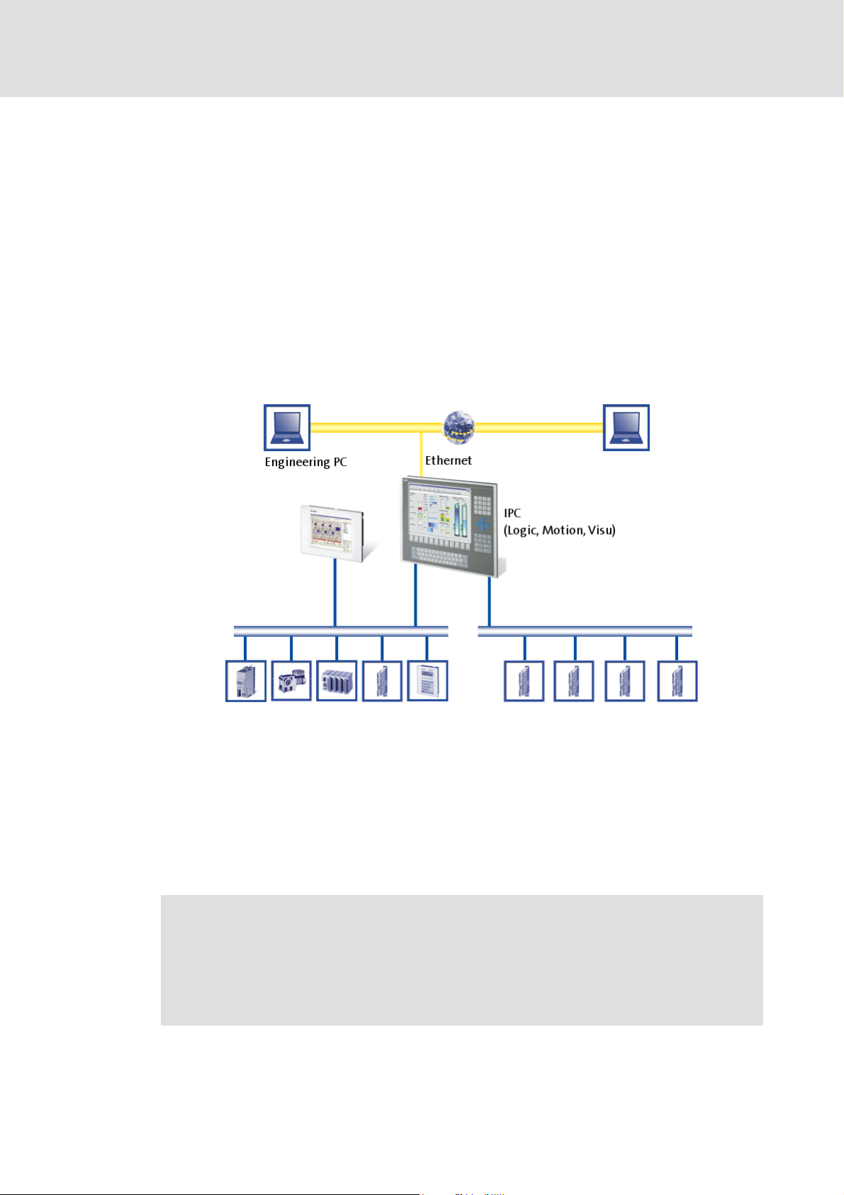
The "PC-based Automation" system enables the central control of Logic and Motion
systems.
The "PC-based Automation" system
For this purpose, Lenze provides coordinated system components:
Industrial PCs as control and visualisation system
– The IPC is the central component of the "PC-based Automation" which control the
Logic and Motion functionalities by means of the runtime software.
– The IPC communicates with the field devices via the fieldbus.
– The IPCs are available in different designs.
Note!
Moreover, the Z EL 1xx PLC HMI series is part of the "PC-based Automation"
system. These devices differ considerably from the Industrial PCs in performance
and various other details. However, the devices of the EL 1xx PLC HMI series are
able to perform smaller control tasks.
DMS 4.2 EN 07/2011 TD17 L 13
Page 14

Control technology | CANopen communication manual
The "PC-based Automation" system
Engineering tools for the Engineering PC
– The Engineering PC communicates with the IPC via Ethernet.
– Different engineering tools serve to configure and parameterise the system.
Fieldbuses
Field devices
14 L DMS 4.2 EN 07/2011 TD17
Page 15
Control technology | CANopen communication manual
4 System bus (CAN) / CANopen
Lenze device series 8200 vector, 9300 and ECS have an on-board system bus (CAN)
connection. The protocol used there is a subset of CANopen. Thus the devices are not
CANopen-conform but can be driven by a CANopen-compatible control under "L-force
Controls" - also in connection with other CANopen-compatible nodes.
4.1 CANopen (Logic) / CANopen (Motion)
System bus (CAN) / CANopen
CANopen (Logic) / CANopen (Motion)
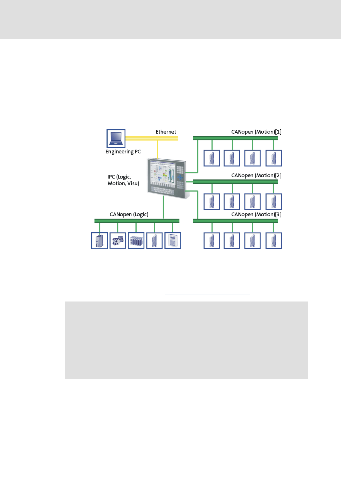
Due to the demands on the real-time behaviour of the bus system and the limited transfer
capacity, the CANopen bus must be divided into a Logic and a Motion bus.
The Logic bus and the Motion buses can be connected to many different field devices.
To establish a CANopen bus, use the Communication card MC-CAN2
( 18).
Note!
Depending on the required Motion node number and bus cycle time, up to 4
Motion buses can be established.
Only 2 buses are possible for the CS x8xx Command Station IPC series.
Conventions for "PC-based Automation"
• Interface CAN1: CANopen (Logic) or CANopen (Motion)
• Interface CAN2 ... 4: CANopen (Motion)
DMS 4.2 EN 07/2011 TD17 L 15
Page 16

Control technology | CANopen communication manual
System bus (CAN) / CANopen
CANopen (Logic) / CANopen (Motion)
CANopen (Logic)
The Logic bus is used to operate controllers which
carry out simple movements,
do not have a Motion functionality,
are controlled via PLC functionalities only.
CANopen (Motion)
The Motion bus is used to control controllers which carry out e.g. synchronised
movements.
The "L-force Motion" runtime software contains the PLCopen libraries and supports the
SoftMotion control to control the "Servo Drives 9400 HighLine CiA402" series and the
"ECSxM" axis module.
4.1.1 Combination with other bus systems
The CANopen bus system can be combined with PROFIBUS. This makes sense if not all field
devices are available for the same bus system or a Motion bus (CANopen) is required in
parallel to the PROFIBUS (as Logic bus). The bus systems are synchronised in the control.
Note!
• A mixed operation is only possible with Industrial PCs which have two
additional slots for communcation cards. A mixed operation is not possible
with the "Command Station".
• Release 2.5 does not facilitate a combination of PROFIBUS and EtherCAT.
• In the control configuration, the PROFIBUS master must be in the first
position – upstream to the CANopen motion nodes.
16 L DMS 4.2 EN 07/2011 TD17
Page 17

4.1.2 Field devices
The Lenze control system supports the following Logic/Motion components:
Standard device Logic Motion
Industrial PCs EL x1xx PLC z -
Servo Drives 9400 HighLine 1) z -
Inverter Drives 8400 BaseLine z -
I/O system IP20 EPM-Txxx z -
I/O system 1000 EPM-Sxxx z -
Frequency inverter 8200 vector z -
ECS servo system
(from firmware version 2.0)
1) with technology application (TA)
Control technology | CANopen communication manual
System bus (CAN) / CANopen
CANopen (Logic) / CANopen (Motion)
EL x8xx zz
CS x8xx zz
CPC x8xx zz
HighLine CiA402 zz
PLC z -
StateLine z -
HighLine z -
TopLine z -
ECSxE z -
ECSXS (Speed & Torque) z -
ECSxP (Posi & Shaft) z -
ECSxM (Motion) - z
ECSxA (Application) z -
DMS 4.2 EN 07/2011 TD17 L 17
Page 18
Control technology | CANopen communication manual
System bus (CAN) / CANopen
CANopen Hardware for your Industrial PC
4.2 CANopen Hardware for your Industrial PC
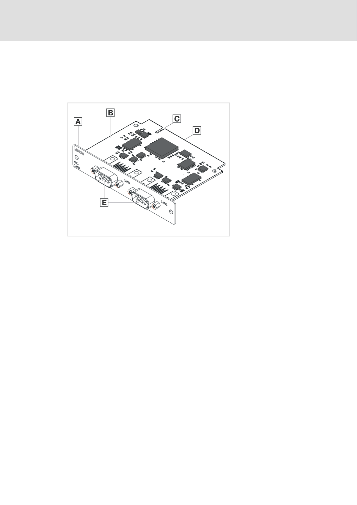
Communication card MC-CAN2
The MC-CAN2 communication card is a plug-in card to connect an Industrial PC to a CAN
fieldbus. It has two independent CAN bus connections.
A Front panel
B Board
C Coding
D Connection
E Fieldbus connection
MC-CAN2-001
Technical data of the MC-CAN2 communication card
( 21)
18 L DMS 4.2 EN 07/2011 TD17
Page 19
Control technology | CANopen communication manual
System bus (CAN) / CANopen
CANopen Hardware for your Industrial PC
Possible applications
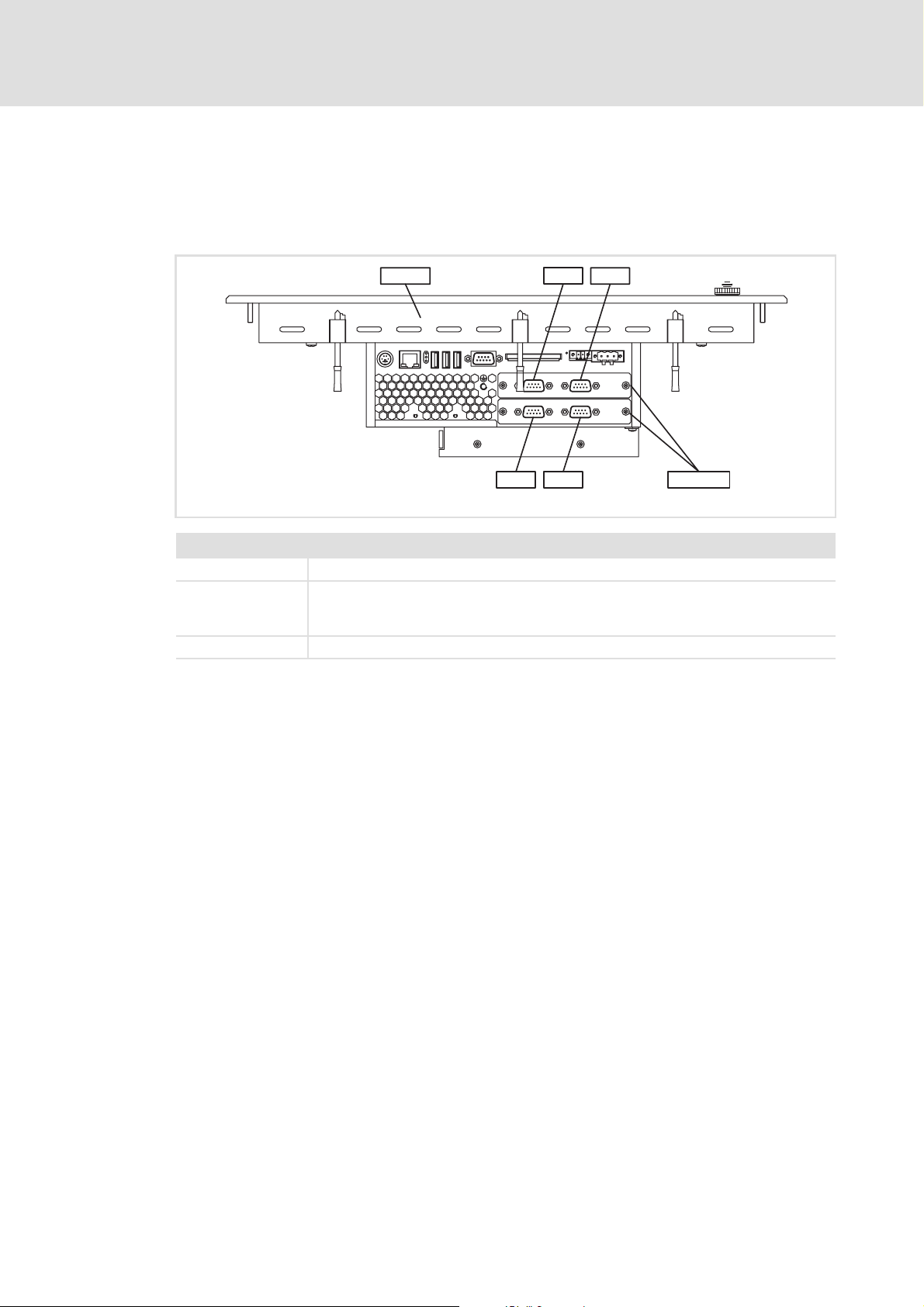
The MC-CAN2 communication card can be plugged into slot 1 and slot 2 of the Industrial
PC. Your Industrial PC can have several CANopen communication cards.
Example: The EL x8xx Industrial PC with MC-CAN2 in slots 1 and 2
EL x8xx
Legend
EL x8xx Industrial PC of the EL x8xx series
CAN1 ... 4 CAN bus connections
•CAN1: CANopen (Logic) or CANopen (Motion)
• CAN2 ... 4: CANopen (Motion)
MC-CAN2 Communication card MC-CAN2
CAN3
CAN1
CAN4
CAN2
l
l
MC-CAN2
MC-CAN2_ELx8xx
DMS 4.2 EN 07/2011 TD17 L 19
Page 20

Control technology | CANopen communication manual
Technical data
General data
5 Technical data
5.1 General data
Field Values
Communication profile CANopen (DS301, V4.02)
Standards CAN, ISO 11898 / EN 50325-4
Network topology Line, terminated at both ends with 120 Ω
(e.g. terminated with Sub-D plug of type EWZ0046)
Max. number of nodes 127
Adjustable node addresses 1 ... 127
(adjustable for Lenze communication modules via DIP switches)
Baud rates [kbps] • 10
•20
•50
• 125
• 250
• 500
• 1000
Parameter data Max. 10 client and server SDO channels with 1 ... 8 bytes
Cycle time - Motion/CNC task 1 ... 16 ms
Max. number of drives/ms on the
Motion bus
Signal propagation delay - drive
control drive
Cross communication Only possible with CANopen (Logic)
Number of DI + DO (bits/ms) 384 (max. 6 PDOs/ms on the Logic bus)
Cycle synchronisation with locked
PLL (Jitter)
Max. 3 drives/ms
4 cycles
In case of CANopen (Motion) the communication is executed centrally via
the Industrial PC.
+/-10 μs
20 L DMS 4.2 EN 07/2011 TD17
Page 21
Control technology | CANopen communication manual
Technical data of the MC-CAN2 communication card
5.2 Technical data of the MC-CAN2 communication card
Field Values
Type within the network Master or slave
Max. number of nodes 63
Max. baud rate [kbit/s] 1000
Bus length See Bus cable length
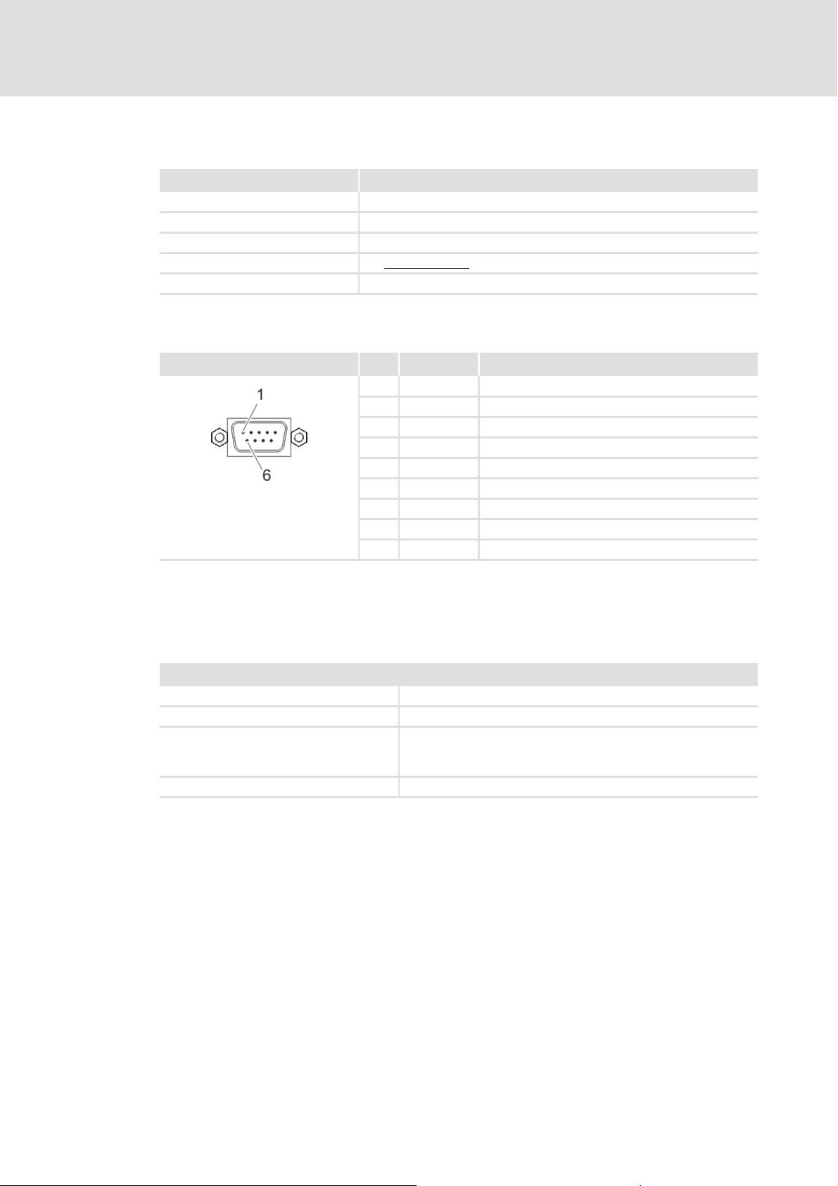
Connection SUB-D, 9-pole plug
CANopen bus connection (SUB-D, 9-pole plug)
View Pin Assignment Description
1free -
2LO CAN-LOW
3CG CAN-Ground
4free -
5free -
6CG CAN-Ground
7HI CAN-HIGH
8free -
9free -
( 22)
Technical data
5.3 Bus cable specification
We recommend to use CAN cables according to ISO 11898-2:
CAN cables according to ISO 11898-2
Cable type Paired cable with shield
Impedance 120 Ω (95 ... 140 Ω)
Cable resistance / cross-section
Cable length ≤ 300 m:
Cable length 301 ... 1000 m:
Signal propagation delay ≤ 5 ns/m
≤ 70 mΩ/m / 0.25 ... 0.34 mm
≤ 40 mΩ/m / 0.5 mm
2
(AWG20)
2
(AWG22)
DMS 4.2 EN 07/2011 TD17 L 21
Page 22

Control technology | CANopen communication manual
Technical data
Bus cable length
5.4 Bus cable length
Note!
• It is absolutely necessary to comply with the permissible cable lengths.
• Observe the reduction of the total cable length due to the signal delay of the
repeater.Check use of repeater
• If the total cable lengths of the nodes are different at the same baud rate, the
smaller value must be used to determine the max. cable length.
5.4.1 Total cable length
The total cable length is also specified by the baud rate.
Baud rate [kbps] Max. bus length [m]
10 8075 - 5000 5000 7434 -
20 4012 - 2500 2500 3934 -
50 1575 1620 1000 1000 1534 1500
125 600 600 500 500 614 630
250 275 260 250 250 274 290
500 112 90 80 80 104 120
1000 12 5 25 25 9 25
9400 Servo
Drives
Inverter
Drives 8400
( 24)
I/O-System
IP20
(EPM-Txxx)
CAN gateway
I/O-System
1000
(EPM-Sxxx)
CANopen bus
coupler
8200 vector
frequency
inverter
Servo System
ECS
22 L DMS 4.2 EN 07/2011 TD17
Page 23

Control technology | CANopen communication manual
5.4.2 Segment cable length
The segment cable length is determined by the used cable cross-section and the number of
nodes. Repeaters divide the total cable length into segments. Without a repeater, the
segment cable length corresponds to the total cable length.
Technical data
Bus cable length
Max. number of
nodes per segment
2 240 m 430 m 650 m 940 m
5 230 m 420 m 640 m 920 m
10 230 m 410 m 620 m 900 m
20 210 m 390 m 580 m 850 m
32 200 m 360 m 550 m 800 m
63 170 m 310 m 470 m 690 m
100 150 m 270 m 410 m 600 m
Cable cross-section (interpolation is permissible)
0.25 mm
(AWG 24)
2
0.50 mm
(AWG 21)
2
0.75 mm
(AWG 19)
2
1.00 mm
(AWG 18)
Example: Selection help
Given:
Total cable length to be
implemented
Number of nodes 63
Results
Max. possible baud rate 250 kbps
Required cable cross-section
(interpolated)
Cable cross-section - standard CAN
cable
200 m
(derived from table Total cable length
0.30 mm
(derived from table Segment cable length
0.34 mm
Bus cable specification
2
(AWG23)
2
(AWG22)
( 21)
( 22))
( 23))
2
DMS 4.2 EN 07/2011 TD17 L 23
Page 24

Control technology | CANopen communication manual
Technical data
Bus cable length
5.4.3 Check use of repeater
Compare the values from the tables Total cable length
( 23).
( 22) and Segment cable length
If the total segment cable length is shorter than the total cable length to be
implemented, either repeaters must be used or the cable cross-section must be
increased.
If, due to the use of repeaters, the max. possible total cable length is reduced to a value
smaller than the total cable length to be implemented, either the cable cross-section
must be increased and the number of repeaters must be reduced or the baud rate must
be reduced.
The use of another repeater is recommended as ...
– Service interface
Advantage: Trouble-free coupling during bus operation is possible.
– Calibration interface
Advantage: The calibration/programming unit remains electrically isolated.
Example
Given
Total cable length to be
implemented
Number of nodes 32
Cable cross-section 0.50 mm
Baud rate 125 kbit/s
Used repeater Lenze repeater EMF2176IB
Reduction of the max. total cable
length per repeater (EMF2176IB)
450 m
30 m
2
(AWG 21)
Results
Max. possible total cable length 600 m
(cp. table Total cable length
Max. segment cable length 360 m
(cp. table Segment cable length
Comparison The max. segment cable length is shorter than the total cable length to be
implemented.
Conclusion After the determined max. segment cable length of 360 m at the latest, a
repeater must be used.
Results with 1 repeater
Max. possible total cable length 570 m
(Reduction of the Total cable length
Total segment cable length 720 m
Comparison Both the possible total cable length and the segment cable length are longer
than the total cable length to be implemented.
Conclusion One repeater suffices to implement the total cable length of 450 m.
( 22))
( 23))
( 22) by 30 m)
24 L DMS 4.2 EN 07/2011 TD17
Page 25

Control technology | CANopen communication manual
6 Planning the CANopen network
Before establishing a CANopen network, create a plan of your Logic bus and/or your
Motion buses.
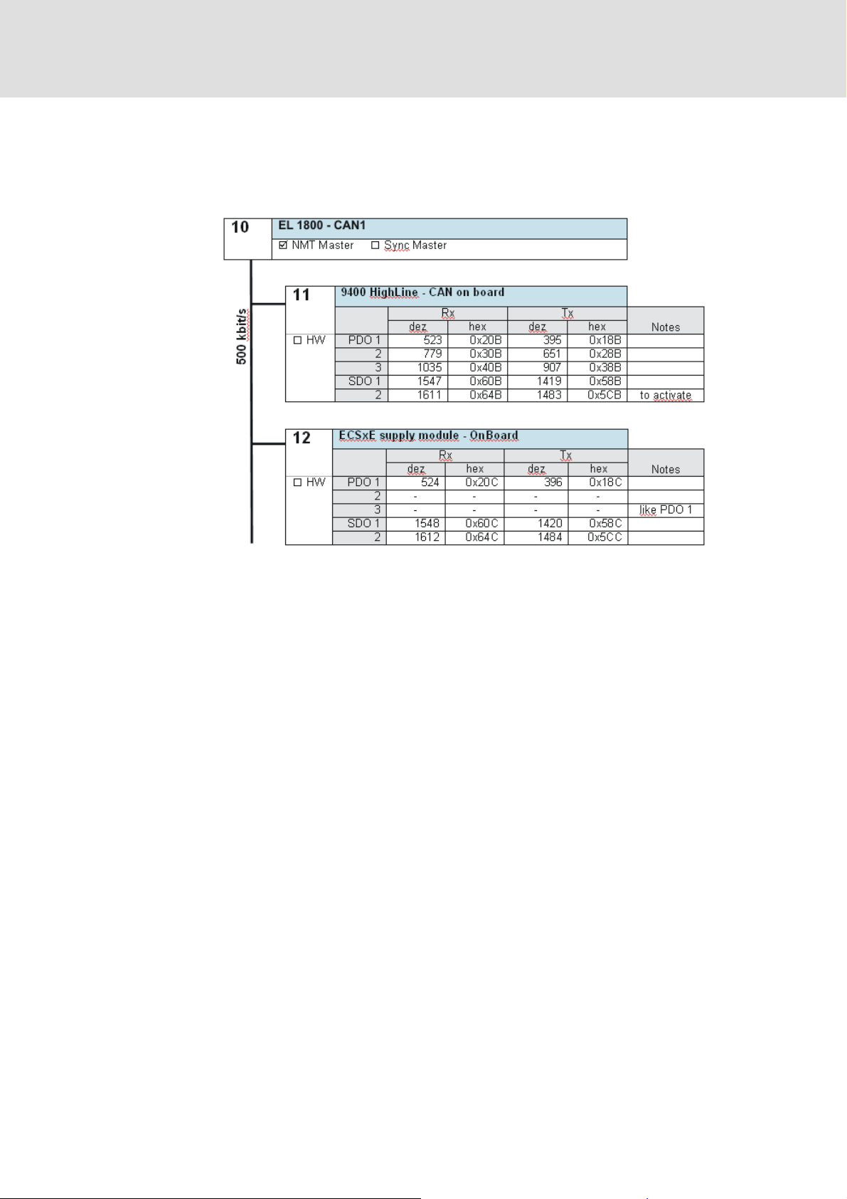
For this purpose, create an overview screen of the planned CANopen network with all field
devices to be implemented. Start with the Industrial PC and arrange the other field devices
below it. (see Example of an overview screen
Provide the following data for each device:
Type Type designation of the field device
Used CAN interface of the device "Logic before Motion":
• Always connect an existing Logic bus to the 1st CAN interface (CAN1).
• Motion buses, however, can be connected to every CAN interface.
CANopen (Logic) / CANopen (Motion)
Unambiguous CAN node address • If system bus (CAN) devices are used, max. 63 nodes/node addresses are
Baud rate • The baud rate applies to all nodes of the CANopen network.
Master role of the device
(NMT master/sync master)
CAN objects and COB-IDs • Plan your COB-IDs according to the CANopen DS301 communication profile.
possible.
• With CANopen-compliant devices, up to 127 nodes/node addresses are
possible.
Note: Do not use the node address 1, in order to avoid unintentional mistakes
and conflicts with a device containing the factory adjustment.
• 50, 125, 250 and 500 kbit/s are supported by all device types of the system.
• Observe the dependency between bus cable length and baud rate. Bus
cable length ( 22)
•An NMT master
In this state, process data can be communicated. Generally, there can be an
optional number of NMT masters on one CANopen bus.
• A sync master
simultaneous processing of process data and/or a simultaneous task start in
all sync receivers.
• Via CAN synchronisation you can influence the exact time of the following
events in the field device:
–Acceptance and transmission of sync-controlled PDOs
–Starting time of the task of the application (only possible for Servo Drives
9400)
• You only need to use CAN synchronisation on the Logic bus if an exact
simultaneity in the range of milliseconds is of importance. A mere operating
periphery (operator button, control lamps, etc.) does not require CAN
synchronisation.
This convention is optimised for the communication with a central master
device.COB-IDs acc. to DS301
• Up to 4 PDOs per device can be identified with this scheme. If you require
more, e.g. for a modular I/O system with more than 8 modules, you can add
them later.
• You can easily assign the node during the bus diagnostics by means of the
COB-IDs.
• COB-ID = basic identifier + node address
Planning the CANopen network
( 28)).
( 15)
sets itself and then the NMT slaves to the "Operational" state.
cyclically sends a sync telegram providing for an exactly
( 26)
DMS 4.2 EN 07/2011 TD17 L 25
Page 26

Control technology | CANopen communication manual
Planning the CANopen network
Observe device-specific information on CAN configuration provided in the
documentation of the field devices to be integrated.
COB-IDs acc. to DS301
Object Direction Basic identifier
from the drive to the drive Dec Hex
NMT 0 0
Sync 128 80
Time Stamp 256 100
Emergency z 128 80
PDO1
(process data channel 1)
PDO2
(process data channel 2)
PDO3
(process data channel 3)
PDO4
(process data channel 4)
SDO
(parameter data channel 1)
NMT Error Control z 1792 700
TPDO1
RPDO1
TPDO2
RPDO2
TPDO3
RPDO3
TPDO4
RPDO4
z 384 180
z 640 280
z 896 380
z 1152 480
z 1408 580
z 512 200
z 768 300
z 1024 400
z 1280 500
z 1536 600
Note!
In system bus (CAN) devices, two SDO channels are permanently active, in
CANopen devices, only one by default.
When using CANopen devices, activate a second SDO channel for accesses of the
»Engineer« or »Global Drive Control«. Otherwise the communication with the
device will be interfered if you go online with the »Engineer« or the »Global
Drive Control«, while the IPC has also access.
26 L DMS 4.2 EN 07/2011 TD17
Page 27

Control technology | CANopen communication manual
Planning the CANopen network
The COB-IDs for your CANopen network can be calculated according to the following
formula:
COB-ID = basic identifier + node address
Basic identifier - 9400 Servo Drives
Basic identifier - 8400 Inverter Drives ( 31)
Basic identifier - I/O system IP20 (EPM-Txxx) ( 32)
Basic identifier - I/O system 1000 (EPM-Sxxx) ( 33)
Basic identifier - 8200 vector with fieldbus function module CANopen E82ZAFUC0xx
( 34)
Basic identifier - ECS servo system ( 36)
( 30)
DMS 4.2 EN 07/2011 TD17 L 27
Page 28
Control technology | CANopen communication manual
Planning the CANopen network
Example of an overview screen
6.1 Example of an overview screen
The illustration shows you an example of an overview screen for planning a CANopen
network:
28 L DMS 4.2 EN 07/2011 TD17
Page 29

Control technology | CANopen communication manual
6.2 Device specifications of the field devices
When planning your CANopen network, consider the device specifications of the
implemented field devices.
Overview of the device specifications when being operated subordinate to a control
Servo Drives 9400 Inverter Drives 8400 I/O-System IP20
CAN interface on board and/or
Available PDOs 4 Transmit (Tx) +
Can unused PDOs be
deactivated?
Can PDO COB-IDs be freely
selected?
Can PDO transfer characteristics
be adjusted?
Available SDO channels 1 ex works (fixed),
Can SDO COB-IDs be freely
selected?
CANopen module
4 Receive (Rx)
yes yes yes
yes yes yes
yes yes yes
9 further can be activated
only for channel 2 ... 10 no no
Planning the CANopen network
Device specifications of the field devices
(EPM-Txxx)
on board on board
3 Transmit (Tx) +
3 Receive (Rx)
2 ex works (fixed) 2 ex works
10 Transmit (Tx) +
10 Receive (Rx)
(Only possible with V1.3
in CANopen mode.)
I/O-System 1000
(EPM-Sxxx)
CAN interface on board Fieldbus fu nction module
Available PDOs 10 Transmit (Tx) +
10 Receive (Rx)
Can unused PDOs be
deactivated?
Can PDO COB-IDs be freely
selected?
Can PDO transfer characteristics
be adjusted?
Available SDO channels 1 ex works (fixed),
Can SDO COB-IDs be freely
selected?
yes yes no
yes yes yes
yes yes yes
1 more can be activated
no no no
8200 vector frequency
inverter
CANopen E82ZAFUC0xx
3 Transmit (Tx) +
3 Receive (Rx)
1 ex works (fixed),
1 more can be activated
ECS servo system
2 x CAN on board:
•Terminal X4: Motion
bus (CAN)
• Terminal X14: System
bus (CAN)
1 Transmit (Tx) +
1 Receive (Rx)
2 ex works (fixed)
DMS 4.2 EN 07/2011 TD17 L 29
Page 30

Control technology | CANopen communication manual
Planning the CANopen network
Device specifications of the field devices
6.2.1 Special features of the Servo Drives 9400
The parameter data channel 1 is always active.
The optional parameter data channels 2 ... 10 can be activated via the subcodes of the
codes Cxx372 and Cxx373.
SDO identifier Code
CANopen SDO server Rx identifier C00372: CAN on board
C13372: Module in slot 1
C14372: Module in slot 2
CANopen SDO server Tx identifier C00373: CAN on board
C13373: Module in slot 1
C14373: Module in slot 2
If bit 31 is set (0x8nnnnnnn
), the corresponding SDO server is deactivated.
hex
In order to change the COB-ID of a currently active parameter data channel, you have
to first deactivate it and then activate it with a changed COB-ID. Both processes must
be rendered effective by a "Reset Node" command via C00002.
Basic identifier - 9400 Servo Drives
The default setting of the basic identifier is as follows:
Object Direction Basic identifier
NMT 0 0
Sync 1) 128 80
Emergency z 128 80
PDO1
(process data channel 1)
PDO2
(process data channel 2)
PDO3
(process data channel 3)
PDO4
(process data channel 4)
SDO1
(parameter data channel 1)
SDO2 ... 10
(parameter data channel 2 ... 10)
Node guarding, heartbeat z 1792 700
TPDO1
RPDO1
TPDO2
RPDO2
TPDO3
RPDO3
TPDO4
RPDO4
TSDO1
RSDO1
TSDOx
RSDOx
from the drive to the drive dec hex
z 384 180
z 512 200
z 640 280
z 768 300
z 896 380
z 1024 400
z 1152 480
z 1280 500
z 1408 580
z 1536 600
z 1472 5C0
z 1600 640
1) When creating the sync transmit/receive identifier manually, observe the use of the emergency telegram because of
the same COB-ID.
30 L DMS 4.2 EN 07/2011 TD17
Page 31

Control technology | CANopen communication manual
6.2.2 Special features of the Inverter Drives 8400
Basic identifier - 8400 Inverter Drives
The default setting of the basic identifier is as follows:
Object Direction Basic identifier
from the drive to the drive dec hex
NMT 00
Sync 1) 128 80
Emergency z 128 80
PDO1
(process data channel 1)
PDO2
(process data channel 2)
PDO3
(process data channel 3)
SDO1
(parameter data channel 1)
SDO2
(parameter data channel 2)
Heartbeat z 1792 700
Boot-up 2) z 1792 700
TPDO1
RPDO1
TPDO2
RPDO2
TPDO3
RPDO3
TSDO1
RSDO1
TSDO2
RSDO2
z 384 180
z 640 280
z 768 300
z 1408 580
z 1472 5C0
Planning the CANopen network
Device specifications of the field devices
z 512 200
z 641 281
z 769 301
z 1536 600
z 1600 640
1) When creating the sync transmit/receive identifier manually, observe the use of the emergency telegram because of
the same COB-ID.
2) When the boot-up identifier is set manually, observe the use of heartbeat because of the same COB-ID.
DMS 4.2 EN 07/2011 TD17 L 31
Page 32

Control technology | CANopen communication manual
Planning the CANopen network
Device specifications of the field devices
6.2.3 Special features for the I/O-System IP20 (EPM-Txxx)
EPM T110 V1.2 has fixed parameter data channels, in CANopen mode as well.
EPM T110 V1.3 has only one parameter data channel in CANopen mode.
Basic identifier - I/O system IP20 (EPM-Txxx)
The default setting of the basic identifier is as follows:
Object Direction Basic identifier
from the drive to the drive dec hex
NMT 0 0
Sync 1) 128 80
Emergency z 128 80
PDO1
(process data channel 1)
PDO2
(process data channel 2)
PDO3
(process data channel 3)
PDO4
(process data channel 4)
PDO5
(process data channel 1)
PDO6
(process data channel 2)
PDO7
(process data channel 3)
PDO8
(process data channel 4)
PDO9
(process data channel 1)
PDO10
(process data channel 2)
SDO1
(parameter data channel 1)
Node guarding z 1792 700
TPDO1
RPDO1
TPDO2
RPDO2
TPDO3
RPDO3
TPDO4
RPDO4
TPDO5
RPDO5
TPDO6
RPDO6
TPDO7
RPDO7
TPDO8
RPDO8
TPDO9
RPDO9
TPDO10
RPDO10
TSDO1
RSDO1
z 384 180
z 640 280
z 896 380
z 1152 480
z 1664 680
z 448 1C0
z 704 2C0
z 960 3C0
z 1216 4C0
z 1728 6C0
z 1408 580
z 512 200
z 768 300
z 1024 400
z 1280 500
z 1920 780
z 576 240
z 832 340
z 1088 440
z 1344 540
z 1984 7C0
z 1536 600
1) When creating the sync transmit/receive identifier manually, observe the use of the emergency telegram because of
the same COB-ID.
32 L DMS 4.2 EN 07/2011 TD17
Page 33

Control technology | CANopen communication manual
Device specifications of the field devices
6.2.4 Special features of the I/O-System 1000 (EPM-Sxxx)
Basic identifier - I/O system 1000 (EPM-Sxxx)
The default setting of the basic identifier is as follows:
Object Direction Basic identifier
from the drive to the drive dec hex
NMT 0 0
Sync 1) 128 80
Emergency z 128 80
PDO1
(process data channel 1)
PDO2
(process data channel 2)
PDO3
(process data channel 3)
PDO4
(process data channel 4)
PDO5
(process data channel 1)
PDO6
(process data channel 2)
PDO7
(process data channel 3)
PDO8
(process data channel 4)
PDO9
(process data channel 1)
PDO10
(process data channel 2)
SDO1
(parameter data channel 1)
Node guarding z 1792 700
TPDO1
RPDO1
TPDO2
RPDO2
TPDO3
RPDO3
TPDO4
RPDO4
TPDO5
RPDO5
TPDO6
RPDO6
TPDO7
RPDO7
TPDO8
RPDO8
TPDO9
RPDO9
TPDO10
RPDO10
TSDO1
RSDO1
z 384 180
z 640 280
z 896 380
z 1152 480
z 1664 680
z 448 1C0
z 704 2C0
z 960 3C0
z 1216 4C0
z 1728 6C0
z 1408 580
Planning the CANopen network
z 512 200
z 768 300
z 1024 400
z 1280 500
z 1920 780
z 576 240
z 832 340
z 1088 440
z 1344 540
z 1984 7C0
z 1536 600
1) When creating the sync transmit/receive identifier manually, observe the use of the emergency telegram because of
the same COB-ID.
DMS 4.2 EN 07/2011 TD17 L 33
Page 34

Control technology | CANopen communication manual
Planning the CANopen network
Device specifications of the field devices
6.2.5 Special features of the 8200 vector frequency inverter
Basic identifier - 8200 vector with fieldbus function module CANopen E82ZAFUC0xx
The default setting of the basic identifier is as follows:
Object Direction Basic identifier
from the drive to the drive dec hex
NMT 0 0
Sync 1) 128 80
Emergency z 128 80
PDO1
(process data channel 1)
PDO2
(process data channel 2)
PDO3
(process data channel 3)
SDO1
(parameter data channel 1)
SDO2
(parameter data channel 2)
Node guarding z 1792 700
TPDO1
RPDO1
TPDO2
RPDO2
TPDO3
RPDO3
TSDO1
RSDO1
TSDO2
RSDO2
z 384 180
z 512 200
z 640 280
z 768 300
z 896 380
z 1024 400
z 1408 580
z 1536 600
z 1472 5C0
z 1600 640
1) When creating the sync transmit/receive identifier manually, observe the use of the emergency telegram because of
the same COB-ID.
34 L DMS 4.2 EN 07/2011 TD17
Page 35

Control technology | CANopen communication manual
6.2.6 Special features of the ECS servo system
Modules of the ECS servo system
Module Type Application software CANopen CAN interface
Power supply module ECSxE - z -X4
Axis module ECSXS "Speed and Torque" z -X4
ECSxP "Posi and Shaft" z -X4
ECSxM "Motion" - z X4
ECSxA "Application" (PLC) z -X4 or X14
Capacitor module ECSxK - No CAN communication
Special features of the ECSxE power supply module
In case of ECSxE power supply modules one refers to CAN1 and CAN3. In fact, here there is
one single process data channel (PDO). It is referred to as CAN1 if it operates in a synccontrolled manner and as CAN3 if it operates in a time or event-controlled manner. CAN1
and CAN3 cannot be used at the same time. The change-over of the transmission mode
and therefore between CAN1 and CAN3 is effected in C0360. The ECSxE power supply
module has no CAN2.
Planning the CANopen network
Device specifications of the field devices
Logic Motion
For historical reasons, the ECSxE power supply module has several subcodes for setting the
PDO properties.
Code Subcodes Description
C0353 1, 3 Mode for ID creation (COB-ID) CAN-IN/OUT
C0354 1, 3 ID offset CAN-IN/OUT
C0355 1, 3 CAN-IN/OUT identifier (COB-IDs), read only
C0356 1, 3, 4 CAN3-IN/OUT time settings: cycle time, activation delay
C0357 1, 3 CAN-IN monitoring
The existence of these subcodes does not
mean that they are independent PDOs. The
respective subcode that is effective depends on the setting in C0360. The subcodes 2 with
regard to CAN2 do not have any effect.
DMS 4.2 EN 07/2011 TD17 L 35
Page 36

Control technology | CANopen communication manual
Planning the CANopen network
Device specifications of the field devices
Basic identifier - ECS servo system
The default setting of the basic identifier is as follows:
Object Direction Basic identifier
from the drive to the drive dec hex
NMT 00
Sync 128 80
PDO1
(process data channel 1)
PDO2
(process data channel 2)
PDO3
(process data channel 3)
SDO1
(parameter data channel 1)
SDO2
(parameter data channel 2)
Heartbeat z 1792 700
Boot-up 1) z 1792 700
TPDO1
RPDO1
TPDO2
RPDO2
TPDO3
RPDO3
TSDO1
RSDO1
TSDO2
RSDO2
z 384 180
z 512 200
z 640 280
z 641 281
z 768 300
z 769 301
z 1408 580
z 1536 600
z 1472 5C0
z 1600 640
1) When the boot-up identifier is set manually, observe the use of heartbeat because of the same COB-ID.
Devices with two active parameter data channels (SDO) respond with a fieldbus scan in the
address range 1 ... 127 with two node addresses each (with offset 64).
36 L DMS 4.2 EN 07/2011 TD17
Page 37

Control technology | CANopen communication manual
7 Preparing the field devices
7.1 Installing field devices
Install the field devices according to the data given in the device-specific mounting
instructions.
Make sure that ...
the CANopen installation complies with your overview screen.
all devices are supported by the control technology system on the Logic bus and Motion
bus.
in case of devices with several CAN interfaces, the correct interfaces are connected to
the fieldbus.
a terminating resistor is connected to the first and last node.
Preparing the field devices
Installing field devices
the fieldbus is not unintentionally interrupted in switchable CAN connectors.
7.2 Setting node addresses and the baud rate
Set the intended node address and baud rate at the field devices.
The easiest way to do this is using the DIP switches (if provided at the device).
Mark the devices the settings of which you have changed in your overview screen.
Attach address labels to the devices.
Note!
• Each node address must be unambiguous and may only be assigned once in
the CANopen network.
• The baud rate must be set identically for all nodes.
• Observe the dependency between bus cable length and baud rate. Bus
cable length ( 22)
DMS 4.2 EN 07/2011 TD17 L 37
Page 38

Control technology | CANopen communication manual
Preparing the field devices
Connecting the Engineering PC to the Industrial PC
7.3 Connecting the Engineering PC to the Industrial PC
To commission the field devices, an online connection is required between the Engineering
PC and the field device. To establish an online connection between an Engineering PC and
a field device (like a controller), two ways are possible:
Direct coupling IPC as gateway
If the control is not started yet, directly connect the Engineering PC to the CANopen bus to
commission the field devices. To activate the Engineering PC, use e.g. the USB system bus
adapter (EMF2177IB). Then the download times are optimal and is it not necessary to
commission the control first.
As soon as the control has been commissioned, no direct coupling should be used anymore
since it may disturb the real-time capability of the bus. This especially applies to the bus
line CANopen Motion bus. Here, the transmission of the sync telegram on time can be
prevented so that an increased jitter on the fieldbus may be the result.
Moreover, each field device requires a second parameter data channel in case of an
independent bus access by two masters. For some device types, the parameter data
channel must be installed separately, e.g. in case of the 9400 Servo Drives.
As an option, some controllers can operate two independent CAN interfaces (e.g. ECS servo
system). In this case, one interface can be used for the connection with the control system,
the other for direct coupling of the Engineering PC. Thus, two buses are created which are
physically independent. In this case, the real-time capability of the nodes at the Motion bus
cannot be influenced even with direct coupling. However, the wiring effort increases.
38 L DMS 4.2 EN 07/2011 TD17
Page 39

Control technology | CANopen communication manual
Preparing the field devices
Connecting the Engineering PC to the Industrial PC
The communication speed with the field devices, when being commissioned, mainly
depends on whether the control is running or stopped. In the latter case, the total
bandwidth of the bus is available for the gateway so that the speed advantage in case of
direct coupling would only be marginal. Thus, the use of the IPC as gateway within the
scope of the control technology should be clearly preferred.
Depending on the standard device and connection type used, detailed
information about establishing a connection and "going online" can be found in
the documentation listed below:
• (Software) manual/online help "PC-based Automation"
Industrial PC - Parameter setting & Configuration
• Software manual/online help "PC based automation"
IPC as gateway - Parameter setting & Configuration
• Software manual/online help »Global Drive Control«
IPC as gateway - Parameterisation & Configuration
• Software manual/online help L-force »Engineer«
DMS 4.2 EN 07/2011 TD17 L 39
Page 40

Control technology | CANopen communication manual
Commissioning the CANopen Logic bus
Overview of the commissioning steps
8 Commissioning the CANopen Logic bus
This chapter provides information on commissioning the Lenze control system using the
CANopen Logic bus.
Depending on the field devices used, the following Lenze engineering tools are required:
»PLC Designer«
»Engineer«
»Global Drive Control« (GDC)
Tip!
For using other fieldbus systems, you may require further engineering software.
More information can be found in the corresponding communication manuals.
8.1 Overview of the commissioning steps
Step Activity Lenze software to be used
1. Creating a project folder
2. Commissioning of field devices
Going online
3. Creating a PLC program
4. Configuring the CAN master ( 57) »PLC Designer«
5. Integrating field devices (slaves) into the PLC program
6. Setting of CAN parameters and CAN mapping ( 60) »PLC Designer«
7. Creating a program code to control the device
8. Preparing the restart
Commissioning the Servo Drives 9400
Commissioning of 8400 Inverter Drives
Commissioning of I/O system IP20 (EPM-Txxx)
Commissioning of I/O system 1000 (EPM-Sxxx)
Commissioning of 8200 vector frequency inverter
Commissioning of ECS devices
( 43)
( 41)
( 54) »PLC Designer«
( 68) »PLC Designer«
The individual commissioning steps are described in the following. Observe the given
instructions step-by-step to commission your system.
( 42)
( 53)
»Engineer« or
»Global Drive Control«
( 44)
( 47)
( 50)
( 51)
( 52)
( 59) »PLC Designer«
( 65) »PLC Designer«
(depending on the used
device)
More detailed information about how to work with the Lenze engineering tools
can be found in the corresponding manuals and online helps.
40 L DMS 4.2 EN 07/2011 TD17
Page 41

Control technology | CANopen communication manual
8.2 Creating a project folder
Create a project folder on the engineering PC.
Use this project folder to store the below data generated in the different project
configuration steps:
Project data created in the »Engineer« or »GDC«
The project file created in the »PLC Designer«
Project data of other engineering tools
Tip!
Create a separate project folder for every PROFIBUS configuration for storing the
project files.
Commissioning the CANopen Logic bus
Creating a project folder
DMS 4.2 EN 07/2011 TD17 L 41
Page 42

Control technology | CANopen communication manual
Commissioning the CANopen Logic bus
Commissioning of field devices
8.3 Commissioning of field devices
Parameterise the Lenze field devices connected to the CANopen bus either with the
»Engineer« or with the »GDC«, depending on the device.
The CANopen is exclusively configured with the »PLC Designer«
( 54).
Observe the information on commissioning provided in the documentation of
the field devices.
Tip!
We recommend to commission each field device individually and then integrate
them into the PLC program.
How to commission the field devices:
1. To commission the field devices, you have to go online.
Going online
2. Make the basic settings and CAN settings of the devices integrated in the CANopen
network.
Commissioning the Servo Drives 9400
Commissioning of 8400 Inverter Drives ( 47)
Commissioning of I/O system IP20 (EPM-Txxx) ( 50)
Commissioning of I/O system 1000 (EPM-Sxxx) ( 51)
Commissioning of 8200 vector frequency inverter ( 52)
Commissioning of ECS devices ( 53)
( 43)
( 44)
42 L DMS 4.2 EN 07/2011 TD17
Page 43

8.3.1 Going online
Standard device Going online with connection via
Industrial PC »Global Drive Control« or
Servo Drives 9400 »Engineer« • IPC as gateway
Inverter Drives 8400 »Engineer« • IPC as gateway
I/O system IP20 (EPM-Txxx) »Engineer« or
I/O system 1000 (EPM-Sxxx) »Engineer« • IPC as gateway
8200 vector frequency inverter »Engineer« or
ECS servo system (ECSxE/S/P/M/A) »Global Drive Control« • IPC as gateway
Control technology | CANopen communication manual
Commissioning the CANopen Logic bus
Commissioning of field devices
Ethernet
»WebConfig«
• Diagnostic adapter
• Ethernet module E94AYCEN
• CANopen module E94AYCCA
• CAN device interface
• CAN device interface
• IPC as gateway
»Global Drive Control«
»Global Drive Control«
• CAN device interface
• CAN device interface
• IPC as gateway
• CANopen module E82ZAFUCxxx
• CAN device interface 1)
• CANopen module EMF2178IB
• CAN device interface 1)
1) CANopen only with system bus adapter EMF2177IB (if required, observe standard device specifications!)
Note!
When selecting the connection type, please observe the notes in chapter
"Connecting the Engineering PC to the Industrial PC
" ( 38).
We recommend to use the connection type "IPC as gateway".
Depending on the standard device and connection type used, detailed
information about establishing a connection and "going online" can be found in
the documentation listed below:
• (Software) manual/online help "PC-based Automation"
Industrial PC - Parameter setting & Configuration
• Software manual/online help "PC based automation"
IPC as gateway - Parameter setting & Configuration
• Software manual/online help »Global Drive Control«
IPC as gateway - Parameter setting & Configuration
• Software manual/online help L-force »Engineer«
DMS 4.2 EN 07/2011 TD17 L 43
Page 44

Control technology | CANopen communication manual
Commissioning the CANopen Logic bus
Commissioning of field devices
8.3.2 Commissioning the Servo Drives 9400
How to commission the Servo Drives 9400:
1. Start the »Engineer«.
2. Open and create an »Engineer« project.
• Enter an axis consisting of Servo Drive 9400, device modules, application, and
motor. Type and version of the planned device must comply with the real
device.
3. Set the intended node address and baud rate.
• Hardware setting via DIP switch or
• in the parameter list via codes:
- For "CAN on board" interface: C00350 and C00351
- For CANopen module in slot 1: C13350 and C13351
- For CANopen module in slot 2: C14350 and C14351
The codes can only be parameterised if the node address "0" and the baud rate "0"
are set via the DIP switches (all DIP switches in OFF position).
A change of node address and baud rate gets only effective after a CAN reset node.
4. Set the sync phase position.
• When the "CAN on board" interface is used, set C01122 = 120 μs.
• When a CANopen module is used, set C01122 = 300 μs.
5. Go online with the Servo Drive 9400 and transfer the application to the device.
6. Make the motor rotate and, if required, parameterise the controller settings.
44 L DMS 4.2 EN 07/2011 TD17
Page 45

Control technology | CANopen communication manual
Commissioning the CANopen Logic bus
Commissioning of field devices
7. Connect the signal which are to be communicated with the IPC with ports via the
FB Editor of the »Engineer«. If possible, use the predefined multiplexers and ports
for this purpose.
• If the possible settings of the predefined multiplexers are not sufficient for your
purposes, activate the FB Editor and draw lines.
• Ports are the variables of the application which can be communicated
outwards. In one port, several signals can be combined to a structure. If the
predefined ports are not sufficient for your purposes, you can change the
structure of the ports or define your own ports under the Ports tab. Before this,
you must activate the application in the FB Editor.
• When the function block interconnection is completed and all required ports are
defined, update the project.
• Retransfer the application to the Servo Drive 9400. Execute a "CAN Reset Node"
on the correct interface via C00002. The device now expects its initialisation
through the control. The green CAN-LED at the Servo Drive 9400 or CAN module
is blinking.
DMS 4.2 EN 07/2011 TD17 L 45
Page 46

Control technology | CANopen communication manual
Commissioning the CANopen Logic bus
Commissioning of field devices
8. Export the EDS file.
• To clearly identify the EDS file in the »PLC Designer« during import, clearly
rename the device before export
precede each device name in the »Engineer« with the project name.)
• The »PLC Designer« only displays the device name contained in the EDS file.
Highlight the CAN interface of the Servo Drive 9400 to be connected to the control
in the project tree. Then select the "EDS export …" command from the context
menu.
in the »Engineer«. (you can e.g. manually
9. Save the file to any folder, logically to your total project directory. You should not
change the suggested file name. The »Engineer« reports that the file has been
created.
You must reimport the EDS file after doing the following in the »Engineer« …
• replacing the component,
• changing the module assembly,
• replacing the application,
• adding, deleting, renaming a port under the Ports tab or changing its
application variables,
• adding, deleting function blocks that can be parameterised in the FB Editor or
changing their code number range,
• adding, deleting, or changing user codes in the FB Editor.
If you reimport the EDS file, you should overwrite the existing EDS file. It is not
reasonable to create several file versions with the same device name since you
cannot distinguish them in the »PLC Designer«.
46 L DMS 4.2 EN 07/2011 TD17
Page 47

Control technology | CANopen communication manual
8.3.3 Commissioning of 8400 Inverter Drives
Note!
The basic identifiers for calculating the PDO COB-IDs do not comply with the
DS301 profile. In this case, adapt the COB-IDs accordingly.
Commissioning the CANopen Logic bus
Commissioning of field devices
Basic identifier - 8400 Inverter Drives
( 31)
How to commission the Inverter Drives 8400:
1. Start the »Engineer«.
2. Open or create an »Engineer« project.
• Enter an axis consisting of Inverter Drive 8400, device modules, application, and
motor. Type and version of the planned device must comply with the real
device.
3. Set the intended node address and baud rate.
• Hardware setting via DIP switch or
• in the parameter list via the codes C00350 (node address) and C00351 (baud
rate).
The codes can only be parameterised if the node address "0" and the baud rate "0"
are set via the DIP switches (all DIP switches in OFF position).
A change of node address and baud rate gets only effective after a CAN reset node.
4. Go online with the Inverter Drive 8400 and transfer the application to the device.
5. Make the motor rotate and, if required, parameterise the controller settings.
DMS 4.2 EN 07/2011 TD17 L 47
Page 48

Control technology | CANopen communication manual
Commissioning the CANopen Logic bus
Commissioning of field devices
6. Set "CAN" under the Application Parameters tab in the Control mode field:
48 L DMS 4.2 EN 07/2011 TD17
Page 49

Control technology | CANopen communication manual
Commissioning the CANopen Logic bus
Commissioning of field devices
7. Export the EDS file.
• To clearly identify the EDS file in the »PLC Designer« during import, clearly
rename the device before export
precede each device name in the »Engineer« with the project name.)
• The »PLC Designer« only displays the device name contained in the EDS file.
Highlight the CAN interface of the Inverter Drive 8400 to be connected to the
control in the project tree. Then select the "EDS export …" command from the
context menu.
in the »Engineer«. (you can e.g. manually
8. Save the file to any folder, logically to your total project directory. You should not
change the suggested file name. The »Engineer« reports that the file has been
created.
You must reimport the EDS file after doing the following in the »Engineer« …
• replacing the application,
• adding, deleting, renaming a port under the Ports tab or changing its
application variables,
• adding, deleting function blocks that can be parameterised in the FB Editor or
changing their code number range.
If you reimport the EDS file, you should overwrite the existing EDS file. It is not
reasonable to create several file versions with the same device name since you
cannot distinguish them in the »PLC Designer«.
DMS 4.2 EN 07/2011 TD17 L 49
Page 50

Control technology | CANopen communication manual
Commissioning the CANopen Logic bus
Commissioning of field devices
8.3.4 Commissioning of I/O system IP20 (EPM-Txxx)
Note!
CAN settings must be made in the »PLC Designer« since the settings are
transferred from the control to the I/O system.
The I/O system can be parameterised in three ways:
Parameter setting with the »Engineer«
1. Start the »Engineer«.
2. Open or create an »Engineer« project.
3. Insert the I/O system as component.
4. Go online with the I/O system via the CANopen bus.
5. Parameterise the I/O system.
6. Save the parameter set with mains failure protection via C16380.
Parameter setting with the »Global Drive Control«
1. Start the »GDC«.
2. Start the search for controllers at the CANopen bus and select the found I/O
system.
Or first select the I/O system offline and then go online.
3. Parameterise the I/O system.
4. Save the parameter set with mains failure protection via CANopen Index 1010.
Parameter setting from the control
In this case you can implement the I/O system immediately into the PLC program and
enter the required values into the Control Configuration under the Service Data
Objects tab.
This is appropriate if you only want to change a few parameters compared to the Lenze
default setting and know the values to be set.
50 L DMS 4.2 EN 07/2011 TD17
Page 51

Control technology | CANopen communication manual
8.3.5 Commissioning of I/O system 1000 (EPM-Sxxx)
Note!
CAN settings must be made in the »PLC Designer« since the settings are
transferred from the control to the I/O system.
The I/O system can be parameterised in two ways:
Parameter setting with the »Engineer«
1. Start the »Engineer«.
2. Open or create an »Engineer« project.
3. Insert the I/O system as component.
4. Go online with the I/O system via the CANopen bus.
Commissioning the CANopen Logic bus
Commissioning of field devices
5. Parameterise the I/O system.
6. Save the parameter set with mains failure protection via CANopen Index 1010.
Parameter setting from the control
In this case you can implement the I/O system immediately into the PLC program and enter
the required values into the Control Configuration under the Service Data Objects tab.
DMS 4.2 EN 07/2011 TD17 L 51
Page 52

Control technology | CANopen communication manual
Commissioning the CANopen Logic bus
Commissioning of field devices
8.3.6 Commissioning of 8200 vector frequency inverter
Note!
• For CAN communication, plug on the fieldbus function module CANopen
(E82ZAFUCxxx).
• CAN settings must be made in the »PLC Designer« since the settings are
transferred from the control to the 8200 vector frequency inverter.
Parameter setting with the »Global Drive Control«
1. Start the »GDC«.
2. Start the search for controllers at the CANopen bus and select the found 8200
vector frequency inverter.
Or first select the suitable 8200 vector frequency inverter with fieldbus function
module CANopen (E82ZAFUCxxx) offline and then go online.
3. Parameterise the inverter.
4. Save the parameter set with mains failure protection.
5. Go offline.
52 L DMS 4.2 EN 07/2011 TD17
Page 53

Control technology | CANopen communication manual
8.3.7 Commissioning of ECS devices
Note!
• In the ECS servo system, each device has a parameter memory which is only
created once when the parameter setting is created via the »Global Drive
Control«. This is the difference to CANopen devices where the
parameterisation is written into the field device at each system start.
• The EMF2221IB card module serves to read parameters saved on an SD card
or SmartMedia card into every ECS device.
• Only 1 receive-PDO and 1 transmit-PDO are available.
• The basic identifiers for calculating the PDO COB-IDs do not comply with the
DS301 profile. In this case, adapt the COB-IDs accordingly.
Basic identifier - ECS servo system
• The device has two permanent SDO channels.
Commissioning the CANopen Logic bus
Commissioning of field devices
( 31)
Parameter setting with the »Global Drive Control«
1. Start the »GDC«.
2. Start the search for controllers at the CANopen bus and select the found ECS device.
Or first select the suitable ECS device offline and then go online.
3. Parameterise the ECS device.
4. Save the parameter set with mains failure protection via C0003 = 1.
DMS 4.2 EN 07/2011 TD17 L 53
Page 54

Control technology | CANopen communication manual
Commissioning the CANopen Logic bus
Creating a PLC program
8.4 Creating a PLC program
The »PLC Designer« serves to illustrate the field device topology in the control
configuration.
Tip!
The »PLC Designer« serves to configure CANopen nodes and nodes on other
fieldbus systems.
CANopen with PROFIBUS
( 85)
How to create a PLC program in the »PLC Designer«:
1. Create a new »PLC Designer« project:
• Menu command: FileNew
2. Select the suitable target system from the Target Settings dialog box:
Target system Application with Industrial PC
EL x8xx CS x8xx CPC x8xx EL 1xx PLC
L-force Logic x800 V8.xx.xx zzz -
L-force Logic EL1xx V1.xx ---z
The target systems of the release 2.2/2.3 (L-force Logic/Motion x700) can also be
used for device series EL x8xx, CS x8xx, and CPC x8xx.
3. Confirm the configuration of the target system setting by clicking the OK button.
54 L DMS 4.2 EN 07/2011 TD17
Page 55

4. Create a block:
Note!
The block must contain at least one instruction to function properly.
Control technology | CANopen communication manual
Commissioning the CANopen Logic bus
Creating a PLC program
DMS 4.2 EN 07/2011 TD17 L 55
Page 56

Control technology | CANopen communication manual
Commissioning the CANopen Logic bus
Creating a PLC program
5. Create the control configuration:
•Open the Resources dialog box:
•Open the PLC Configuration dialog box:
Setting Description
Automatic calculation of addresses Every newly added module automatically gets an address which results from
Check for overlapping addresses During the compilation of the project, a check for address overlapping is
Save configuration files in project The data of the configuration file(s) *.cfg and device files on which the
the address of the module integrated before and the size of this module. If a
module is removed from the configuration, the addresses of the subsequent
modules are adapted automatically.
The ExtrasCalculate addresses menu command serves to recalculate the
addresses starting with the currently selected node (module).
carried out and overlapping addresses are indicated.
current control configuration is based are stored in the project.
Note!
We recommend to keep the standard setting. In case of a manual address
allocation, you must ensure that each object address is non-ambiguous in the
entire control configuration.
Detailed information on this can be found in the documentation/online help of
the »PLC Designer«.
56 L DMS 4.2 EN 07/2011 TD17
Page 57

Control technology | CANopen communication manual
8.5 Configuring the CAN master
Note!
An Industrial PC in the CANopen network must be configured in the »PLC
Designer« since the complete configuration of the IPC is written to the Servo
Drives 9400 when the IPC is started. During this process, previous »Engineer«
settings are overwritten.
1. Add the bus interface to the PLC configuration:
Commissioning the CANopen Logic bus
Configuring the CAN master
The "CanMaster" subelement represents the CAN interface of the IPC which is
connected to the Logic bus (typically CAN1).
2. Change to the CAN parameters tab:
DMS 4.2 EN 07/2011 TD17 L 57
Page 58

Control technology | CANopen communication manual
Commissioning the CANopen Logic bus
Configuring the CAN master
Note!
The baud rate set in »PLC Designer« overwrites the baud rate set for the field
devices via »WebConfig«/»Engineer«/»Global Drive Control«.
In a CANopen network, set the same baud rate for all nodes.
• Set the planned baud rate and node address (node ID).
• If you want to use the CAN synchronisation at the Logic bus, set a checkmark in
the "Activate" input field. This is only required if at least one PDO with synccontrolled processing is used on the fieldbus and/or if you want to achieve that
the applications run in synchronism in several controllers (slaves).
• The sync cycle time can be set in the "Com. Cycle Period" input field.
Enter an integer multiple of the cycle time of the assigned task (see 3., module
parameters) as sync cycle time.
• Activate the DSP support. This is required so that the IPC CANopen-conform
Logic initialises field devices.
3. Specify the "UpdateTask" and its corresponding cycle time in the Module
parameters tab by double-clicking the "Value" field:
• As "UpdateTask", enter the name of the task which accesses the CAN bus. If
more than one task has access to the CAN bus, enter the task with the shortest
cycle time.
• All CAN telegrams are received and transmitted within the time base of this
task. This also applies to the sync telegram which however is not transmitted
more frequently than the set sync cycle time.
• Communication from different tasks is not possible.
4. Your PLC program is now ready for the Logic field devices to be integrated.
Save your PLC project.
58 L DMS 4.2 EN 07/2011 TD17
Page 59

Control technology | CANopen communication manual
Commissioning the CANopen Logic bus
Integrating field devices (slaves) into the PLC program
8.6 Integrating field devices (slaves) into the PLC program
Note!
• EDS files regarding the I/O system IP20 (EPM-Txxx), the I/O system 1000
(EPM-Sxxx), Frequency Inverters 8200 with CANopen fieldbus function
modules (E82ZAFUCxxx), and other ECS devices can be found on the Internet
in the Services & Downloads area of the Lenze homepage. Please be sure to
always use the latest EDS file and also observe the software versions.
• EDS files for Servo Drives 9400 and Inverter Drives 8400 must be created via
the »Engineer«.
See:
Commissioning the Servo Drives 9400
Commissioning of 8400 Inverter Drives ( 47)
• You can also integrate EDS files for devices of other manufacturers into the
PLC program.
( 44)
How to integrate field devices into the PLC program:
1. Import the device-specific EDS file in the »PLC Designer« via the menu item
ExtrasAdd configuration file.
2. Add the corresponding field device as a "subelement" below the CAN master via
the Control configuration.
The field device appears in the selection list with the same name as during the
export of the EDS file in the »Engineer«, extended by the name of the interface and
device type.
3. Give the entered element a name which …
• only contains the characters A ... Z, a ... z, 0 ... 9 and _ ,
• does not start with a digit.
Example:
DMS 4.2 EN 07/2011 TD17 L 59
Page 60

Control technology | CANopen communication manual
Commissioning the CANopen Logic bus
Setting of CAN parameters and CAN mapping
8.7 Setting of CAN parameters and CAN mapping
How to set CAN parameters and CAN mapping:
1. Change to the CAN parameters tab of the corresponding slave:
– Set the CAN node address and baud rate in accordance with the settings of the field
devices.
– Set node guarding, emergency telegram, and communication cycle if you need them
for your application.
– CAN Logic bus slaves provide the monitoring function of the communication cycle
(area: "Communication Cycle"). The function can be switched on/off in the »PLC
Designer« interface. If no sync telegram is received within the set monitoring time,
the slave triggers an error message.
Note!
Switching on/off the monitoring function of the communication cycle in the
»PLC Designer« is transmitted incorrectly to the slave or not at all. The last active
state is kept in the slave (once active, always active).
60 L DMS 4.2 EN 07/2011 TD17
Page 61

Control technology | CANopen communication manual
Commissioning the CANopen Logic bus
Setting of CAN parameters and CAN mapping
2. Change to the Receive PDO-Mapping / Send PDO-Mapping tab:
• Here, configure the PDOs the field device is to receive and transmit. Define the
transmission properties.
• The ports of the application are on the left, the available PDOs of the used
interface are on the right. Define suitable transmission properties for the PDOs
to be filled. Remove the PDOs which cannot be transmitted.
• Mapped variables in the PDOs also appear in the control configuration tree.
• We recommend to set the "cyclic - synchronous" transmission type and to
specify the number of syncs at which the PDOs are to be sent.
• The settings of the event time via the "PDO properties - ..." dialog are not
evaluated.
Note!
If you operate a fieldbus without CAN synchronisation, please observe the
following:
• The control system always transmits asynchronous PDOs from an unsolicited
task in an event-controlled way. To achieve a time-controlled transmission of
asynchronous PDOs by the control system, you must assign the CAN master
to a cyclic task.
• The control does not support any monitoring times for asynchronous receive-
PDOs. This is only possible with field devices.
DMS 4.2 EN 07/2011 TD17 L 61
Page 62

Control technology | CANopen communication manual
Commissioning the CANopen Logic bus
Setting of CAN parameters and CAN mapping
Cross communication between the slaves
When the CAN bus is used for control, a cross communication between the slaves is
possible.
For this purpose, you must configure the CAN communication and the PDO mapping in the
»Engineer« or in the »Global Drive Control« and write it into the controller.
Since the mapping for the cross communication between the slaves is not available in the
control configuration, you must set the "Not initialise" option in the »PLC Designer« in the
CAN parameters tab:
Thus, the CAN and mapping settings in the slave drives will not be overwritten by the
control when the PLC program starts.
Note!
In addition to the cross communication between the slaves, the communication
to the master in the »Engineer« or in the »Global Drive Control« must be
configured as well. Also this part of the PDO mapping will not be written
anymore when the "Not initialise" option is active.
62 L DMS 4.2 EN 07/2011 TD17
Page 63

Control technology | CANopen communication manual
8.7.1 Special features of the 9400 Servo Drives
The mapping required for cross-communication between the control and the slaves must
be created in the »PLC Designer«. When the PLC is started, the complete configuration /
PDO mapping is written to the Servo Drives 9400. During this process, previous mapping
entries from the »Engineer« are overwritten.
Commissioning the CANopen Logic bus
Setting of CAN parameters and CAN mapping
Please also observe the notes regarding Cross communication between the slaves
8.7.2 Special features of the 8400 Inverter Drives
The mapping required for cross-communication between the control and the slaves must
be created in the »PLC Designer«. When the PLC is started, the complete configuration /
PDO mapping is written to the Inverter Drives 9400. During this process, previous mapping
entries from the »Engineer« are overwritten.
Please also observe the notes regarding Cross communication between the slaves
8.7.3 Special features of the I/O modules IP20 "1×counter/16×digital input" and "SSI interface"
The I/O modules support the system bus (CAN) and CANopen operating modes. In
connection with the control technology, set CANopen.
The module 1×counter/16×digital input always assigns the next to last and the SSI
interface module always the last of the PDOs used.
The modules cannot be assigned to PDO1 and PDO2. Thus, only eight of these modules
can be maximally used in a system.
The modules assign a whole PDO (8 bytes) each.
( 62).
( 62).
8.7.4 Special features of the 8200 vector frequency inverter
The standard mapping corresponds to the Lenze setting of the 8200 vector frequency
inverter.
In the standard setting, sync-controlled PDOs are used.
DMS 4.2 EN 07/2011 TD17 L 63
Page 64

Control technology | CANopen communication manual
Commissioning the CANopen Logic bus
Setting of CAN parameters and CAN mapping
8.7.5 Special features of the ECS servo system
1. Set the process data transfer in the ECS device.
Process data channel CAN3 (event-controlled/cyclic without sync telegram):
• C0360 = 0
• Use individual addressing from C0354: C0353/3 = 1
• COB-ID of the receive-PDO1: C0354/5 = 128 + node address
• COB-ID of the transmit-PDO1: C0354/6 = node address
• Transmit-cycle time: C0356/3
Process data channel CAN1 (synchronised/cyclic with sync telegram):
• C0360 = 1
• Use addressing from C0350: C0353/1 = 0
2. Trigger a "CAN reset node": C0358 = 1
3. Save the parameter set: C0003 = 1
64 L DMS 4.2 EN 07/2011 TD17
Page 65

Control technology | CANopen communication manual
Creating a program code to control the device
8.8 Creating a program code to control the device
Note!
All program blocks which are operated with an SDO communication must be
called up in a Logic task. Otherwise, jobs will get lost.
1. Create the program code to control the field device. The device must be used in the
program code so that the SDO initialisation can take place.
If you insert more devices in the control configuration, the addresses of the
existing % variables may change. Thus, do not use any % variables directly in the
program code but allocate separate names:
Commissioning the CANopen Logic bus
2. Compile the program and transfer it to the control system.
8.8.1 Special features of the Servo Drives 9400
When the program starts, the control initialises the Servo Drive 9400. The controller
changes to the "Operational" state.
8.8.2 Special features of the Inverter Drives 8400
When the program starts, the control initialises the Inverter Drive 8400. The frequency
inverter changes to the "Operational" state.
DMS 4.2 EN 07/2011 TD17 L 65
Page 66

Control technology | CANopen communication manual
Commissioning the CANopen Logic bus
Creating a program code to control the device
8.8.3 Special features of the I/O system IP20 (EPM-Txxx)
The I/O modules support the system bus (CAN) and CANopen operating modes. In
connection with the control technology, set CANopen.
When the program starts, the control initialises the I/O system. It changes to the
"Operational" state.
While the control initialises the I/O system, »Engineer« or »Global Drive Control« must
not be online on the same SDO channel.
Operate the I/O system in the "CANopen" mode.
If you operate it in the "Lenze system bus" mode, specify in the program code that a
"reset node" is transmitted after initialisation. Do not use the SDO "reset node" under
the Service Data Objects tab as the control would try endlessly to initialise the I/O
system.
8.8.4 Special features of the I/O system 1000 (EPM-Sxxx)
When the program starts, the control initialises the I/O system. It changes to the
"Operational" state.
When the control initialises the I/O system, the »Engineer« must not be online on the
same SDO channel.
Set the "Reset Node" command under the "Service Data Objects" tab.
8.8.5 Special features of the 8200 vector frequency inverter
When the program is started, the control initialises the 8200 vector frequency inverter.
The fieldbus function module CANopen (E82ZAFUCxxx) connected to the 8200 vector
frequency inverter changes to the "Operational" state. The lower green LED is lit
constantly.
While the control initialises the 8200 vector frequency inverter, the »Global Drive
Control« must not be online on the same SDO channel.
66 L DMS 4.2 EN 07/2011 TD17
Page 67

Control technology | CANopen communication manual
8.8.6 Special features of the ECS servo system
When the program is started, the control initialises the ECS device:
– The control transmits, as common for CANopen, the CAN settings. However, the
device as a Lenze system bus device does not accept these settings.
– The control transmits the SDOs of the Service Data Objects tab if you changed
anything there.
– The control transmits an "NMT Start Remote Node" telegram. The device changes to
the "Operational" state.
While the control initialises the ECS device, the »Global Drive Control« must not be
online on the same SDO channel.
The ECSxE and ECSxM devices support toggle bit monitoring, which can cause the "TRIP
CE4" error.
– You can either program that the control cyclically changes the state of bit 0 in each
transmitted PDO. The first transmitted control word must be 0 after the initialisation
phase is completed, or
– deactivate the toggle bit monitoring function in the device:
for ECSxE with C0595 = 3, for ECSxM with C3160 = 3.
Commissioning the CANopen Logic bus
Creating a program code to control the device
DMS 4.2 EN 07/2011 TD17 L 67
Page 68

Control technology | CANopen communication manual
Commissioning the CANopen Logic bus
Preparing the restart
8.9 Preparing the restart
In the control technology system you can use the control to transmit the entire parameter
setting via SDO initialisation to the field devices when the machine is switched on.
According to DS301, the control always initialises the CAN parameters of the field devices.
Moreover, it can initialise further parameters. The values for this must be stored in the
control configuration under the Service Data Objects tab.
Usually, the control only transmits those SDO projects for which you have stored another
value than the standard value. The control does not
values in the field device. Thus, not all parameters changed there may be set correctly.
If you want that a factory adjustment is carried out in the field device before SDO
initialisation, go to the Parameter tab and set a checkmark at "Reset Node".
compare these values with the existing
Note!
When a node is reset, the parameter setting in the field device which you have
made with the »Engineer« or the »Global Drive Control« gets lost. For this reason
you have to transmit all parameter values manually to the Service Data Objects
tab. This only makes sense when commissioning is completed and all
parameters are optimised. If you change something afterwards via the
»Engineer« or the »Global Drive Control«, you have to maintain it in the PLC
program.
The Service Data Objects tab contains the codes which are written in the EDS file. The EDS
file contains all write codes.
68 L DMS 4.2 EN 07/2011 TD17
Page 69

Control technology | CANopen communication manual
8.9.1 Special features of the Servo Drives 9400
Servo Drives 9400 are not purely parameterisable devices. They require an application
download, where several files are transmitted to the memory module.
To operate a Servo Drive 9400,
plug on the memory module.
transmit the application using the »Engineer«. For this, you must keep the original
»Engineer« project.
transmit the application using the L-force »Loader«. For this, you must export and keep
the required files from the »Engineer« project:
Commissioning the CANopen Logic bus
Preparing the restart
8.9.2 Special features of the Inverter Drives 8400
Inverter Drives 8400 are purely parameterisable devices.
To operate an Inverter Drive 8400, you can transmit the application using the »Engineer«.
For this, you must keep the original »Engineer« project.
DMS 4.2 EN 07/2011 TD17 L 69
Page 70

Control technology | CANopen communication manual
Commissioning the CANopen Logic bus
Preparing the restart
8.9.3 Special features of the I/O-System IP20 (EPM-Txxx)
Note!
For the SDO initialisation of the I/O system, please observe that ...
• a factory adjustment sets the I/O system to the system bus mode.
– In connection with control technology, set CANopen.
• when being in the system bus mode, the I/O system only accepts changed
CAN settings after a "reset node" has been executed.
• the control does not transmit a "reset node" after the SDO initialisation,
unless you have programmed it accordingly.
Thus the following strategies are possible for the I/O system restart:
Automatic:
You want the control to automatically initialise the I/O system after the device has
been replaced.
– Operate the I/O system in CANopen mode.
– Enter all required parameter values in the Control Configuration under the Service
Data Objects tab.
– Go to the Parameters tab and do not
the control does not execute a factory adjustment.
– Go to the Parameters tab and set a checkmark at Create all SDOs in order that the
control initialises all parameters.
– After changing the I/O system:
Set the node address and baud rate at the coding switch for the CANopen mode and
then start the control.
set a checkmark at "Reset Node" in order that
Using the »Engineer« or the »Global Drive Control«:
1. You have implemented the I/O system successfully into the PLC program.
2. You have parameterised some codes of the I/O system using the »Engineer« or the
»Global Drive Control«.
3. You do not want to transmit the parameter setting to the control configuration now,
since you can assume that after a possible device replacement a project planning tool
will be available.
– Operate the I/O system in CANopen mode.
– Go to the Parameters tab and do not
the control does not execute a factory adjustment.
– Keep the »Engineer« project or the »Global Drive Control« file at the machine.
– After changing the I/O system:
Set the node address and baud rate at the coding switch for the CANopen mode and
transmit the archived parameter setting to the I/O system. Then start the control.
set a checkmark at "Reset Node" in order that
70 L DMS 4.2 EN 07/2011 TD17
Page 71

Control technology | CANopen communication manual
Automatic with factory adjustment:
With an automatic restart, a factory adjustment is executed.
– Enter all required parameter values in the Control Configuration under the Service
Data Objects tab.
– Set the checkmark at "Reset Node" in order that the control executes the factory
adjustment. This causes the I/O system to change to the "Lenze System Bus" mode
and remains there.
– Program a "Reset Node" in your program code. Do not
under the Service Data Objects tab. Otherwise the initialisation will be repeated
endlessly.
– After changing the I/O system:
Set the node address and baud rate at the coding switch for the CANopen mode and
then start the control.
8.9.4 Special features of the I/O-System 1000 (EPM-Sxxx)
Commissioning the CANopen Logic bus
Preparing the restart
use the SDO "Reset Node"
There are different viable strategies for the I/O system restart:
Automatic:
You want the control to automatically initialise the I/O system after the device has
been replaced.
– Enter all required parameter values in the Control Configuration under the Service
Data Objects tab.
– Go to the Parameters tab and do not
the control does not execute a factory adjustment.
– Go to the Parameters tab and set a checkmark at Create all SDOs in order that the
control initialises all parameters.
– After changing the I/O system:
Set the node address and baud rate at the coding switch and then start the control.
Using the »Engineer«:
1. You have implemented the I/O system successfully into the PLC program.
2. You have parameterised some CANopen indexes of the I/O system using the
»Engineer«.
3. You do not want to transmit the parameter setting to the control configuration now,
since you can assume that after a possible device replacement a project planning tool
will be available.
– Operate the I/O system in CANopen mode.
– Go to the Parameters tab and do not
the control does not execute a factory adjustment.
– Save the »Engineer« project near the machine.
– After changing the I/O system:
Set the node address and baud rate at the coding switch and transmit the archived
parameter setting to the I/O system. Then start the control.
set a checkmark at "Reset Node" in order that
set a checkmark at "Reset Node" in order that
DMS 4.2 EN 07/2011 TD17 L 71
Page 72

Control technology | CANopen communication manual
Commissioning the CANopen Logic bus
Preparing the restart
Automatic with factory adjustment:
With an automatic restart, a factory adjustment is executed.
– Enter all required parameter values in the Control Configuration under the Service
Data Objects tab.
– Set a checkmark at Reset Node for the control to perform the factory adjustment.
– Set the "Reset Node" command under the "Service Data Objects" tab.
– After changing the I/O system:
Set the node address and baud rate at the coding switch and then start the control.
8.9.5 Special features of the ECS servo system
In the ECS servo system, each device has a parameter memory which is only created
once when the parameter setting is created via the »Global Drive Control«. This is the
difference to CANopen devices where the parameterisation is written into the field
device at each system start.
The EMF2221IB card module serves to read parameters saved on an SD card or
SmartMedia card into every ECS device.
When using ECS devices, you cannot set all codes/parameters via the Service Data
Objects tab as the EDS files do not contain all codes/parameters.
72 L DMS 4.2 EN 07/2011 TD17
Page 73

Control technology | CANopen communication manual
Commissioning the CANopen Motion bus
9 Commissioning the CANopen Motion bus
This chapter provides information on commissioning the Lenze control system using the
CANopen Motion bus.
Depending on the field devices used, the following Lenze engineering tools are required:
»PLC Designer«
»Engineer«
»Global Drive Control« (GDC)
Tip!
For using other fieldbus systems, you may require further engineering software.
More information can be found in the corresponding communication manuals.
Overview of the commissioning steps
9.1 Overview of the commissioning steps
Step Activity Lenze software to be used
1. Commissioning of field devices
2. Creating a PLC program
3. Creating a Motion task
4. Creating a control configuration
5. Creating a program code to control the Motion drives
6. Preparing the restart
7. Optimisation of signal propagation delays (for HighLine CiA402 only)
( 83)
( 82) »PLC Designer«
( 74) »Engineer« or
( 75) »PLC Designer«
( 78) »PLC Designer«
( 79) »PLC Designer«
»Global Drive Control«
(depending on the used
device)
( 82) »PLC Designer«
»PLC Designer«
DMS 4.2 EN 07/2011 TD17 L 73
Page 74

Control technology | CANopen communication manual
Commissioning the CANopen Motion bus
Commissioning of field devices
9.2 Commissioning of field devices
Not all parameters required for operating a Motion drive are set automatically via the
control.
Set the following parameters manually via the »Engineer« or the »Global Drive Control«:
Servo Drives 9400 HighLine CiA402:
– Homing mode (C02640, to be set machine-dependent)
– Touch-probe interface (to be set machine-dependent)
– The behaviour is automatically set via the control after the home position is
detected.
– Sync phase position:
- When the "CAN on board" interface is used, set C01122 = 120 μs.
- When a CANopen module is used, set C01122 = 300 μs.
ECSxM axis module:
– Touch-probe source (C0428, to be set machine-dependent)
– Touch-probe dead time compensation (C0429, to be set machine-dependent)
– Touch-probe edge (C0431, to be set machine-dependent)
– Homing mode (C3010, to be set machine-dependent)
– Synchronisation phase (C01122=0.46ms = (Lenze setting))
– Control of a possibly existing holding brake (0x60FB/2 | Brake control)
Depending on the setting of this parameter, the holding brake is applied for a short
time after the conclusion of the home position path. In order to avoid this, set the
bit 2 in this parameter (disable stop => does not apply the brake in standstill).
74 L DMS 4.2 EN 07/2011 TD17
Page 75

Control technology | CANopen communication manual
9.3 Creating a PLC program
The »PLC Designer« serves to illustrate the field device topology in the control
configuration.
Tip!
The »PLC Designer« serves to configure CANopen nodes and nodes on other
fieldbus systems.
Commissioning the CANopen Motion bus
Creating a PLC program
CANopen with PROFIBUS
( 85)
How to create a PLC program in the »PLC Designer«:
1. Create a new »PLC Designer« project:
• Menu command: FileNew
2. In the Target settings dialog box, select the L-force Motion x800 V8.xx.xx target
system:
The target systems of the release 2.2/2.3 (L-force Logic/Motion x700) can also be
used for device series EL x8xx, CS x8xx, and CPC x8xx.
3. Confirm the configuration of the target system setting by clicking the OK button.
DMS 4.2 EN 07/2011 TD17 L 75
Page 76

Control technology | CANopen communication manual
Commissioning the CANopen Motion bus
Creating a PLC program
4. Create a block:
Note!
The block must contain at least one instruction to function properly.
76 L DMS 4.2 EN 07/2011 TD17
Page 77

Control technology | CANopen communication manual
5. Create the control configuration:
•Open the Resources dialog box:
•Open the PLC Configuration dialog box:
Commissioning the CANopen Motion bus
Creating a PLC program
Setting Description
Automatic calculation of addresses Every newly added module automatically gets an address which results from
the address of the module integrated before and the size of this module. If a
module is removed from the configuration, the addresses of the subsequent
modules are adapted automatically.
The ExtrasCalculate addresses menu command serves to recalculate the
addresses starting with the currently selected node (module).
Check for overlapping addresses During the compilation of the project, a check for address overlapping is
carried out and overlapping addresses are indicated.
Save configuration files in project The data of the configuration file(s) *.cfg and device files on which the
current control configuration is based are stored in the project.
Note!
We recommend to keep the standard setting. In case of a manual address
allocation, you must ensure that each object address is non-ambiguous in the
entire control configuration.
Detailed information on this topic can be found in the documentation/online
help of the »PLC Designer«.
DMS 4.2 EN 07/2011 TD17 L 77
Page 78

Control technology | CANopen communication manual
Commissioning the CANopen Motion bus
Creating a Motion task
9.4 Creating a Motion task
How to create a Motion task:
1. Go to the »PLC Designer« and change to Task Configuration.
2. Insert a new task and assign an appropriate task name (e.g. "Motion task")
• in the "Name" input field and
• in the task configurator tree (left window). A mouse-click on "NewTask" will
activate the name for editing.
3. Enter an appropriate cycle time in milliseconds in the "Type" area under "Features"
in the "Interval" input field.
The cycle time to be entered depends on the number of Motion axes and the
runtime of the PLC application. In case of a small PLC application, the minimum
cycle time (T
rate of the CANopen bus.
) is determined by the number of Motion axes due to the transfer
cycl
T
[ms] = number of Motion axes / 3
cycl
4. Add a program call to the task (e.g. "Motion_PRG").
The following task configuration is the result:
5. Compile the new project completely.
Menu bar: ProjectCompile all
78 L DMS 4.2 EN 07/2011 TD17
Page 79

Control technology | CANopen communication manual
9.5 Creating a control configuration
How to create a control configuration:
1. Go to »PLC Designer« and change to control configuration.
2. Add the "BusInterface_CAN " subelement to the "PLC Configuration" basic node.
The "BusInterface_CAN" subelement generally represents the fieldbus connection
via the CANopen (Motion) interfaces of the IPC.
3. Add the H "Axis_Group_CAN" subelement to the "BusInterface_CAN" element.
The "Axis_Group_CAN" subelement represents the single CANopen (Motion)
interface of the IPC (the special Sub-D plug).
4. Assign a task to "Axis_Group_CAN" (e.g. the "Motion task" created before).
Note!
Commissioning the CANopen Motion bus
Creating a control configuration
To prevent the sync telegram from jittering, all Motion phases must be assigned
to the same task.
5. Enter the suitable controller number in the "Controller No." field in the "Specific
Settings" area.
This serves to define the number of the CANopen interface via which the Motion
drives are to be controlled. The following assignment applies:
CAN interface Controller no. Notes
CAN1 0 The CAN1 connection is usually used for the Logic bus. Thus
CAN2 1
CAN3 2
CAN4 3
6. Set the corresponding baud rate of the Motion axes in the "Baud Rate" input field
in the "Specific settings" area.
7. Add the "Drive" subelement to the " Axis_Group_CAN ".
8. Assign an appropriate name for the "Drive" Motion drive (e.g. "Drive_vertical") in
the task configurator tree (left window). With a mouse-click on "Drive", the name
is activated for editing.
9. Adapt the "Drive ID".
the first Motion bus mostly is CAN2.
The "Drive ID" corresponds to the node number of the Motion drive.
10. Enter the value 66536 into the "Increments" input field in the "Conversion Factor"
area.
11. Repeat the steps 7 to 10 until the required number of Motion drives is reached.
DMS 4.2 EN 07/2011 TD17 L 79
Page 80

Control technology | CANopen communication manual
Commissioning the CANopen Motion bus
Creating a control configuration
12. The following control configuration is the result with a minimum configuration
with one drive:
13. A single rotary axis Motion drive (type: rotary, 360° / revolution, ratio 1:1) shall
then be configured as follows:
80 L DMS 4.2 EN 07/2011 TD17
Page 81

Control technology | CANopen communication manual
Commissioning the CANopen Motion bus
Creating a control configuration
When using a linear axis Motion drive (type: linear), you can define the positions of
the software limit switches in the "Settings for linear drive" area.
DMS 4.2 EN 07/2011 TD17 L 81
Page 82

Control technology | CANopen communication manual
Commissioning the CANopen Motion bus
Creating a program code to control the Motion drives
9.6 Creating a program code to control the Motion drives
This depends on the automation task, the use of PLCopen blocks or the CNC programming.
Note!
All SoftMotion function blocks, SoftMotion functions, and the read/write block
parameters that access the SoftMotion drives (e.g. MC_WriteParameter,
MC_WriteBoolParameter, LenzeECSReadParameter, LenzeECSWriteParameter)
may only be called from the Motion task.
If they are called from another task, their execution may be incorrect.
See also "Creating a program code to control the device
9.7 Preparing the restart
Save parameter set of the drive via the »Engineer« or the »Global Drive Control«.
Please also see "Preparing the restart
" (chapter [8.8] ( 65)).
" (chapter [8.9] ( 68)).
82 L DMS 4.2 EN 07/2011 TD17
Page 83

Control technology | CANopen communication manual
Commissioning the CANopen Motion bus
Optimisation of signal propagation delays (for HighLine CiA402 only)
9.8 Optimisation of signal propagation delays (for HighLine CiA402 only)
An optimised setting is possible at a low packing density of the telegrams on the fieldbus.
An optimised setting serves to achieve shorter signal propagation delays (Control
Drive Control) when the packing density is < 0.7:
(Sum of all telegram runtimes) / (set sync cycle time) < 0.7
Telegram runtimes
Telegram/data object Telegram runtime at 500 kbits/s Telegram runtime at 1 Mbits/s
Sync telegram 100 μs 50 μs
Actual value PDO 240 μs 120 μs
Setpoint PDO 240 μs 120 μs
SDO 240 μs 120 μs
9.8.1 Example 1: 3 drives in 1 ms at 1 Mbit/s
Set sync cycle time (C1121): 1000 μs
Set sync phase position (C1122): 120 μs
Telegram runtimes
1 sync telegram 50 μs
1 actual value PDO per drive 360 μs (120 μs x 3 )
1 setpoint PDO per drive 360 μs (120 μs x 3)
1 SDO 120 μs
Sum of all telegram runtimes 890 μs
This results in the following telegram order within one cycle:
Packing density: 890 μs / 1000 μs = 0.89
Use standard setting.
DMS 4.2 EN 07/2011 TD17 L 83
Page 84

Control technology | CANopen communication manual
Commissioning the CANopen Motion bus
Optimisation of signal propagation delays (for HighLine CiA402 only)
9.8.2 Example 2: 4 drives in 2 ms at 1 Mbps
Set sync cycle time (C1121): 2000 μs
Set sync phase position (C1122): 120 μs
Telegram runtimes
1 sync telegram 50 μs
1 actual value PDO per drive 480 μs (120 μs x 4 )
1 setpoint PDO per drive 480 μs (120 μs x 4)
1 SDO 120 μs
Sum of all telegram runtimes 1130 μs
This results in the following telegram order within one cycle:
Packing density: 1130 μs / 2000 μs = 0.565
standard setting or optimised setting possible.
Calculation of the sync phase position for the optimised setting
Sync phase position (C1122) = sync cycle time (C1121) / 2
Thus the following results for example 2:
Sync phase position (C1122): 2000 μs / 2 = 1000 μs
84 L DMS 4.2 EN 07/2011 TD17
Page 85

Control technology | CANopen communication manual
10 CANopen with PROFIBUS
The CANopen bus system can be combined with PROFIBUS. This makes sense if not all field
devices are available for the same bus system or a Motion bus (CANopen) is required in
parallel to the PROFIBUS (as Logic bus). The bus systems are synchronised in the control.
Note!
• A mixed operation is only possible with Industrial PCs which have two
additional slots for communcation cards. A mixed operation is not possible
with the "Command Station".
• Release 2.5 does not facilitate a combination of PROFIBUS and EtherCAT.
• In the control configuration, the PROFIBUS master must be in the first
position – upstream to the CANopen motion nodes.
CANopen with PROFIBUS
"PROFIBUS control technology" communication manual
Here you can find detailed information on how to commission PROFIBUS
components.
Addressing the CANopen and PROFIBUS nodes
The addresses for input and output objects of the PROFIBUS and CANopen stations are
automatically allocated in the »PLC Designer« (standard setting):
Note!
We recommend to keep the standard setting. In case of a manual address
allocation, you must ensure that each object address is non-ambiguous in the
entire control configuration.
Detailed information on this topic can be found in the documentation/online
help of the »PLC Designer«.
DMS 4.2 EN 07/2011 TD17 L 85
Page 86

Control technology | CANopen communication manual
The function library LenzeCANdrive.lib
11 The function library LenzeCANdrive.lib
The LenzeCANdrive.lib function library supports the SoftMotion control to control the
"Servo Drives 9400 HighLine CiA402" series and the "ECSxM" axis module.
Features
• RegulatorOn, DriveStart
• Error message and acknowledgement
• Reading and writing of SoftMotion and drive parameters:
– Access via index 0xaabb
(only required for writing) or
– use of MC_Read/Write(Bool)Parameter with parameter number ddaabbcc
– use of the function blocks LenzeECSReadParameter and LenzeECSWriteParameter to
directly access Lenze codes or
– use of the function blocks SMC_ReadCANParameter and SMC_WriteCANParameter
to address standard CAN objects via the index/subindex.
and subindex 0xcc
hex
with the length 0xdd
hex
in bytes
hex
hex
or
• Reading of drive parameters (as string) with LenzeECSReadString
• Any ratio factors (dwRatioTechUnitsDenom/iRatioTechUnitsNum)
• Linear or rotary axes
• Control modes: position, velocity (9400), torque (9400)
– Use SMC_SetControllerMode to change the mode.
• Drive-internal homing
– ECSxM: Configure C3010, C0935, C0936
Note: During the homing mode, the current position is not
drive!
– Configure 9400: 6098
• Latching: 1 channel (trigger number = 1), only ECSxM
• ECSxM: Depending on the settings in code C3175 the hardware limit switches are
monitored by the control (C3175 = 3) or the drive.
• Configuration from file is possible
• Configuration from dialogs in the PLC configuration is possible
• Supported sync generators (to be set in the PLC configuration, AxisGroup: PLC, 1st drive,
sync device)
hex
, 6099
hex
, 609A
hex
indicated by the ECS
Detailed information on the LenzeCANdrive.lib function library is provided in the
online help of the »PLC Designer« and the software manual »PLC Designer -
SoftMotion«.
86 L DMS 4.2 EN 07/2011 TD17
Page 87

Control technology | CANopen communication manual
Defining the minimum cycle time of the PLC project
Calculating the total access time to the peripheral devices (T
12 Defining the minimum cycle time of the PLC project
This chapter will inform you on how the minimum cycle time of the PLC project can be
defined.
The calculation of the minimum cycle time is divided into the following steps:
Correction
)
1. Calculating the total access time T
Correction
to the peripheral devices.
Calculating the total access time to the peripheral devices (T
2. Detecting the task utilisation T
Task utilisation
Detecting the task utilisation of the application (T
of the application during operation.
Task utilisation
3. Calculating the minimum cycle time.
Calculating the minimum cycle time
( 90)
4. Optimising the system.
Optimising the system
( 91)
12.1 Calculating the total access time to the peripheral devices (T
The cycle times depend on the number of configured field devices and the IPC hardware
used.
Configuration Access time with processor
CAN master (Logic) 80 μs
per axis (Motion) 60 μs
Correction
) ( 88)
Correction
ATOM 1.6 GHz
)
) ( 87)
Example
Access times Industrial PC (ATOM 1.6 GHz) with 9 Motion axes
Access time CAN master
+ access time 9 Motion axes
= total access time 620 μs
80 μs
540 μs
DMS 4.2 EN 07/2011 TD17 L 87
Page 88

Control technology | CANopen communication manual
Defining the minimum cycle time of the PLC project
Detecting the task utilisation of the application (T
Task utilisation
)
12.2 Detecting the task utilisation of the application (T
The time T
this the system is commissioned on the basis of cycle times that are sufficiently long, and
afterwards it is optimised.
In order to detect the task utilisation, use the task editor in the »PLC Designer«.
12.2.1 Display of the system utilisation in the »PLC Designer«with the task Editor
Task utilisation
cannot be calculated. It is determined in the running system. For
Task utilisation
)
Note!
In order to be able to display the utilisation for all tasks, the IEC 61131
SysTaskInfo library must be included in the project.
The task editor contains a dialog window consisting of two parts.
The left part represents the tasks in a configuration tree.
If the Task configuration entry is highlighted, the utilisation for all tasks is shown in bar
diagrams in the right dialog window.
How to display the system utilisation:
1. Select the Resources tab:
2. Open the Task configuration in the online mode of the »PLC Designer«:
88 L DMS 4.2 EN 07/2011 TD17
Page 89

Control technology | CANopen communication manual
Detecting the task utilisation of the application (T
12.2.2 Detecting the task utilisation
Initial situation
A project has been completely created with, for instance, a Motion task and two tasks of
lower priority.
Defining the minimum cycle time of the PLC project
Task utilisation
)
How to detect the task utilisation T
1. For a first measurement of T
system are set to 'long'.
• Example: Motion task = 10 ms, all other cyclic tasks = 20 ms
2. Log in and load project.
3. After the system has started up completely, press the Reset button on the Task
processing tab.
• The displayed task runtimes are reset.
4. Read the maximum computing time of the task with the highest priority that is
shown in the task configuration (T
Task utilisation
Task utilisation
the cycle times of all cyclic tasks in the PLC
Task utilisation
:
).
DMS 4.2 EN 07/2011 TD17 L 89
Page 90

Control technology | CANopen communication manual
Defining the minimum cycle time of the PLC project
Calculating the minimum cycle time
12.3 Calculating the minimum cycle time
Note!
A safety factor of 1.5 is included in the calculation of the minimum cycle time.
The minimum cycle time T
for a system results from the sum of the times detected
min
before, multiplied by the safety factor:
T
> safety factor x ( T
min
Task utilisation
+ T
Correction
)
Example
Configuration: Industrial PC (ATOM 1.6 GHz) with 9 Motion axes
Detected access time Result
Calculated correction value T
Value read from task configuration: T
Actual required computing time 1120 μs
Minimum cycle time including a safety factor of 1.5 T
Actual cycle time 2000 μs
Correction
Task utilisation
min
620 μs
(80 μs + (9 x 60 μs))
500 μs
1680 μs
90 L DMS 4.2 EN 07/2011 TD17
Page 91

Control technology | CANopen communication manual
12.4 Optimising the system
How to optimise the system:
1. Log in and load project.
2. Check the task processing times.
3. Optimising cycle times:
• If required technologically, the cycle times of the remaining tasks with lower
priorities can be decreased.
• Condition: No task with a low priority may assign more than 60 percent of the
corresponding cycle time in its task utilisation.
Defining the minimum cycle time of the PLC project
Optimising the system
DMS 4.2 EN 07/2011 TD17 L 91
Page 92

Control technology | CANopen communication manual
Diagnostics
Reading codes
13 Diagnostics
13.1 Reading codes
The »Engineer« and the »Global Drive Control« contain the corresponding diagnostic
codes.
13.2 Viewing the logbook of the IPC
In the web browser you have access to the logbook of the PC. Use the display filter to search
for entries concerning CANopen.
Note!
"ClearLog" deletes the complete logbook on the IPC without any prompt.
92 L DMS 4.2 EN 07/2011 TD17
Page 93

Control technology | CANopen communication manual
Error messages if communication card MC-CAN2 is not available
13.3 Error messages if communication card MC-CAN2 is not available
If no communication card MC-CAN2 has been inserted into the industrial PC, error messages occur during the download of the »PLC Designer« project.
Remedy: Insert the communication card MC-CAN2 into the industrial PC.
13.4 Searching the CANopen bus for nodes using the Engineering PC
1. First directly connect your notebook via the USB system bus adapter EMF2177IB to
the CANopen bus.
2. Start the program »System bus configurator«:
• in the »Engineer« in the menu bar under "Online"
• or under "Start - Programs - Lenze - Communication"
Diagnostics
3. Activate the USB system bus adapter (EMF2177IB).
4. Check the following under the "Settings" tab:
• baud rate = as on the devices
• parameter data channel = 0:
The entire address range is scanned. Devices responding on several SDO
channels are displayed with several node addresses.
Example:
5. Click the Communication diagnostics button on the Common tab to start the
search.
DMS 4.2 EN 07/2011 TD17 L 93
Page 94

Control technology | CANopen communication manual
Diagnostics
The global variable wState
13.5 The global variable wState
When Motion nodes are used for control, »PLC Designer« displays the current status of the
control acceleration in the global variable wState of the "AxisGroup" structure.
The value of the wState variable has the following meaning:
Status of the AxisGroup State of the system
wState = 0 •Initial state
•Project loaded
• PLC in stop
wState = 1...99 • System is starting up
•Project loaded
•PLC started
wState = 100 • System has started up successfully
wState > 1000 • Error occurred during startup, compare error message in
g_strBootupError
Example for a faulty acceleration:
94 L DMS 4.2 EN 07/2011 TD17
Page 95

Control technology | CANopen communication manual
Diagnostics
The global variable wState
Additional information on the type of error occurred are provided in the global variables of
the SM_DriveBasic.lib function library.
The g_strBootupError variable, for instance, contains an error text:
Here, an SDO access of the control has not been responded by the slave.
DMS 4.2 EN 07/2011 TD17 L 95
Page 96

Control technology | CANopen communication manual
Parameter reference
14 Parameter reference
This chapter adds the parameters of the MC-CAN2 communication card to the parameter
list provided in the online documentation for the Industrial PC:
Parameters of the MC-CAN2 communication card in slot 1
Parameters of the MC-CAN2 communication card in slot 2 ( 98)
( 97)
Note!
• Several MC-CAN2 communication cards can be used per Industrial PC. The
designation of the card in the »WebConfig« is MC-CAN2.
• Depending on the used slot, the code numbers differ by an offset of '500'.
Hence, for a communication card in slot 2, an offset of '500' has been added
to the code numbers of a card in slot 1.
Tip!
General information about parameters is provided in the online documentation for
the Industrial PC.
96 L DMS 4.2 EN 07/2011 TD17
Page 97

Control technology | CANopen communication manual
Parameters of the MC-CAN2 communication card in slot 1
14.1 Parameters of the MC-CAN2 communication card in slot 1
The parameters are listed in numerically ascending order.
Parameter reference
C1031
C1032
C1033
C1034
C1035
Parameter | Name:
C1031 | Device: Identification
Identification of the card
; Read access Write access CINH PLC-STOP No transfer
Parameter | Name:
C1032 | Device: Version
Version number of the card
; Read access Write access CINH PLC-STOP No transfer
Parameter | Name:
C1033 | Device: Name
Device name of the card
; Read access Write access CINH PLC-STOP No transfer
Parameter | Name:
C1034 | Device: Software version
Software version of the card
; Read access Write access CINH PLC-STOP No transfer
Parameter | Name:
C1035 | Device: Hardware version
Hardware version of the card
; Read access Write access CINH PLC-STOP No transfer
Data type: VISIBLE_STRING
Index: 23544
Data type: VISIBLE_STRING
Index: 23543
Data type: VISIBLE_STRING
Index: 23542
Data type: VISIBLE_STRING
Index: 23541
Data type: VISIBLE_STRING
Index: 23540
= 5BF8
d
= 5BF7
d
= 5BF6
d
= 5BF5
d
= 5BF4
d
h
h
h
h
h
C1036
C1037
C1038
Parameter | Name:
C1036 | Device: Serial number
Serial number of the card
; Read access Write access CINH PLC-STOP No transfer
Parameter | Name:
C1037 | Device: Manufacturer
Manufacturer of the card
; Read access Write access CINH PLC-STOP No transfer
Parameter | Name:
C1038 | Device: Manufacturing date
Manufacturing date of the card
; Read access Write access CINH PLC-STOP No transfer
Data type: VISIBLE_STRING
Index: 23539
Data type: VISIBLE_STRING
Index: 23538
Data type: VISIBLE_STRING
Index: 23537
= 5BF3
d
= 5BF2
d
= 5BF1
d
h
h
h
DMS 4.2 EN 07/2011 TD17 L 97
Page 98

Control technology | CANopen communication manual
Parameter reference
Parameters of the MC-CAN2 communication card in slot 2
14.2 Parameters of the MC-CAN2 communication card in slot 2
The parameters are listed in numerically ascending order.
C1531
C1532
C1533
C1534
C1535
Parameter | Name:
C1531 | Device: Identification
Identification of the card
; Read access Write access CINH PLC-STOP No transfer
Parameter | Name:
C1532 | Device: Version
Version number of the card
; Read access Write access CINH PLC-STOP No transfer
Parameter | Name:
C1533 | Device: Name
Device name of the card
; Read access Write access CINH PLC-STOP No transfer
Parameter | Name:
C1534 | Device: Software version
Software version of the card
; Read access Write access CINH PLC-STOP No transfer
Parameter | Name:
C1535 | Device: Hardware version
Hardware version of the card
; Read access Write access CINH PLC-STOP No transfer
Data type: VISIBLE_STRING
Index: 23044
Data type: VISIBLE_STRING
Index: 23043
Data type: VISIBLE_STRING
Index: 23042
Data type: VISIBLE_STRING
Index: 23041
Data type: VISIBLE_STRING
Index: 23040
= 5A04
d
= 5A03
d
= 5A02
d
= 5A01
d
= 5A00
d
h
h
h
h
h
C1536
C1537
C1538
Parameter | Name:
C1536 | Device: Serial number
Serial number of the card
; Read access Write access CINH PLC-STOP No transfer
Parameter | Name:
C1537 | Device: Manufacturer
Manufacturer of the card
; Read access Write access CINH PLC-STOP No transfer
Parameter | Name:
C1538 | Device: Manufacturing date
Manufacturing date of the card
; Read access Write access CINH PLC-STOP No transfer
Data type: VISIBLE_STRING
Index: 23039
Data type: VISIBLE_STRING
Index: 23038
Data type: VISIBLE_STRING
Index: 23037
= 59FF
d
= 59FE
d
= 59FD
d
h
h
h
98 L DMS 4.2 EN 07/2011 TD17
Page 99

Control technology | CANopen communication manual
15 Appendix
This chapter describes how to use the »PCAN-View« program for diagnostics of your
CANopen network.
»PCAN-View« is the basic version of the »PCAN-Explorer« program for Windows® of PEAK
System Technik GmbH. The program permits a simultaneous transmission and receipt of
CAN messages which can be sent manually and periodically. Errors on the bus system and
memory overflows of the controlled CAN hardware are displayed.
Finally important information on visualisation using »VisiWinNET®« is provided.
15.1 »PCAN-View« for diagnostic purposes
Monitor telegram traffic on the CANopen bus
1. First directly connect your Engineering PC via the USB system bus adapter
EMF2177IB to the CANopen bus.
Appendix
»PCAN-View« for diagnostic purposes
2. Start the program »PCAN-View«.
3. Connect the »PCAN-View« with "Connect to CAN Hardware" according to the USB
system bus adapter and the baud rate.
Example:
DMS 4.2 EN 07/2011 TD17 L 99
Page 100

Control technology | CANopen communication manual
Appendix
»PCAN-View« for diagnostic purposes
Now the CAN telegrams are constantly displayed in the "Receive" and "Transmit"
windows:
On the basis of the IDs displayed and the IDs in your overview you can assign the telegrams
to the devices.
If no telegrams are displayed, there may be several causes:
• Is your Engineering PC connected to the correct CANopen bus?
• Is the correct system bus adapter activated under "System control, CAN hardware“?
• What does it say in the status bar of the »PCAN-View«?
If it says "Bus Heavy" mostly a node with an incorrect baud rate interferes with the bus
communication.
• Are the devices in the "Operational" state?
100 L DMS 4.2 EN 07/2011 TD17
 Loading...