

Page 1
Automation Systems
Controller-based
Automation
CANopen®
_ _ _ _ _ _ _ _ _ _ _ _ _ _ _ _ _ _ _ _ _ _ _ _ _ _ _ _ _ _ _ _
Communication Manual DE
Ä.O5÷ä
13462098
L
Page 2

Contents
_ _ _ _ _ _ _ _ _ _ _ _ _ _ _ _ _ _ _ _ _ _ _ _ _ _ _ _ _ _ _ _ _ _ _ _ _ _ _ _ _ _ _ _ _ _ _ _ _ _ _ _ _ _ _ _ _ _ _ _ _ _ _ _
1 About this documentation _ _ _ _ _ _ _ _ _ _ _ _ _ _ _ _ _ _ _ _ _ _ _ _ _ _ _ _ _ _ _ _ _ _ _ _ _ _ _ 5
1.1 Document history _ _ _ _ _ _ _ _ _ _ _ _ _ _ _ _ _ _ _ _ _ _ _ _ _ _ _ _ _ _ _ _ _ _ _ _ _ _ _ _ _ _ _ _ 7
1.2 Conventions used _ _ _ _ _ _ _ _ _ _ _ _ _ _ _ _ _ _ _ _ _ _ _ _ _ _ _ _ _ _ _ _ _ _ _ _ _ _ _ _ _ _ _ _ 8
1.3 Terminology used _ _ _ _ _ _ _ _ _ _ _ _ _ _ _ _ _ _ _ _ _ _ _ _ _ _ _ _ _ _ _ _ _ _ _ _ _ _ _ _ _ _ _ _ 9
1.4 Definition of the notes used _ _ _ _ _ _ _ _ _ _ _ _ _ _ _ _ _ _ _ _ _ _ _ _ _ _ _ _ _ _ _ _ _ _ _ _ _ _ 10
2Safety instructions _ _ _ _ _ _ _ _ _ _ _ _ _ _ _ _ _ _ _ _ _ _ _ _ _ _ _ _ _ _ _ _ _ _ _ _ _ _ _ _ _ _ _ _ 11
3 Controller-based Automation: Central motion control _ _ _ _ _ _ _ _ _ _ _ _ _ _ _ _ _ _ _ _ _ _ _ _ 12
4 System bus (CAN) / CANopen _ _ _ _ _ _ _ _ _ _ _ _ _ _ _ _ _ _ _ _ _ _ _ _ _ _ _ _ _ _ _ _ _ _ _ _ _ _ 15
4.1 CANopen (Logic) / CANopen (Motion) _ _ _ _ _ _ _ _ _ _ _ _ _ _ _ _ _ _ _ _ _ _ _ _ _ _ _ _ _ _ _ _ _ 16
4.2 Field devices _ _ _ _ _ _ _ _ _ _ _ _ _ _ _ _ _ _ _ _ _ _ _ _ _ _ _ _ _ _ _ _ _ _ _ _ _ _ _ _ _ _ _ _ _ _ _ 17
4.3 CANopen hardware for Lenze Controllers _ _ _ _ _ _ _ _ _ _ _ _ _ _ _ _ _ _ _ _ _ _ _ _ _ _ _ _ _ _ _ 18
4.4 Lenze Engineering tools _ _ _ _ _ _ _ _ _ _ _ _ _ _ _ _ _ _ _ _ _ _ _ _ _ _ _ _ _ _ _ _ _ _ _ _ _ _ _ _ _ 19
5 Technical data _ _ _ _ _ _ _ _ _ _ _ _ _ _ _ _ _ _ _ _ _ _ _ _ _ _ _ _ _ _ _ _ _ _ _ _ _ _ _ _ _ _ _ _ _ _ 20
5.1 General data _ _ _ _ _ _ _ _ _ _ _ _ _ _ _ _ _ _ _ _ _ _ _ _ _ _ _ _ _ _ _ _ _ _ _ _ _ _ _ _ _ _ _ _ _ _ _ 20
5.2 Technical data of the MC-CAN2 communication card _ _ _ _ _ _ _ _ _ _ _ _ _ _ _ _ _ _ _ _ _ _ _ _ _ 21
5.3 Bus cable specification _ _ _ _ _ _ _ _ _ _ _ _ _ _ _ _ _ _ _ _ _ _ _ _ _ _ _ _ _ _ _ _ _ _ _ _ _ _ _ _ _ 21
5.4 Bus cable length _ _ _ _ _ _ _ _ _ _ _ _ _ _ _ _ _ _ _ _ _ _ _ _ _ _ _ _ _ _ _ _ _ _ _ _ _ _ _ _ _ _ _ _ _ 22
5.4.1 Total cable length _ _ _ _ _ _ _ _ _ _ _ _ _ _ _ _ _ _ _ _ _ _ _ _ _ _ _ _ _ _ _ _ _ _ _ _ _ _ _ 22
5.4.2 Segment cable length _ _ _ _ _ _ _ _ _ _ _ _ _ _ _ _ _ _ _ _ _ _ _ _ _ _ _ _ _ _ _ _ _ _ _ _ _ 22
5.4.3 Use of repeaters _ _ _ _ _ _ _ _ _ _ _ _ _ _ _ _ _ _ _ _ _ _ _ _ _ _ _ _ _ _ _ _ _ _ _ _ _ _ _ _ 23
6 Planning the CANopen network _ _ _ _ _ _ _ _ _ _ _ _ _ _ _ _ _ _ _ _ _ _ _ _ _ _ _ _ _ _ _ _ _ _ _ _ 25
6.1 COB-IDs acc. to DS301 _ _ _ _ _ _ _ _ _ _ _ _ _ _ _ _ _ _ _ _ _ _ _ _ _ _ _ _ _ _ _ _ _ _ _ _ _ _ _ _ _ _ 26
6.2 Example of an overview screen _ _ _ _ _ _ _ _ _ _ _ _ _ _ _ _ _ _ _ _ _ _ _ _ _ _ _ _ _ _ _ _ _ _ _ _ _ 27
6.3 Device specifications of the field devices _ _ _ _ _ _ _ _ _ _ _ _ _ _ _ _ _ _ _ _ _ _ _ _ _ _ _ _ _ _ _ _ 28
6.3.1 Special features of the 9400 Servo Drives _ _ _ _ _ _ _ _ _ _ _ _ _ _ _ _ _ _ _ _ _ _ _ _ _ _ 29
6.3.2 Special features of the 8400 Inverter Drives _ _ _ _ _ _ _ _ _ _ _ _ _ _ _ _ _ _ _ _ _ _ _ _ _ 30
6.3.3 Special features of the I/O system 1000 (EPM-Sxxx) _ _ _ _ _ _ _ _ _ _ _ _ _ _ _ _ _ _ _ _ _ 31
6.4 Special case: Delayed switch-on of one or more slaves _ _ _ _ _ _ _ _ _ _ _ _ _ _ _ _ _ _ _ _ _ _ _ _ 32
7 Preparing the field devices _ _ _ _ _ _ _ _ _ _ _ _ _ _ _ _ _ _ _ _ _ _ _ _ _ _ _ _ _ _ _ _ _ _ _ _ _ _ _ 33
7.1 Installing field devices _ _ _ _ _ _ _ _ _ _ _ _ _ _ _ _ _ _ _ _ _ _ _ _ _ _ _ _ _ _ _ _ _ _ _ _ _ _ _ _ _ _ 33
7.2 Setting node addresses and baud rate _ _ _ _ _ _ _ _ _ _ _ _ _ _ _ _ _ _ _ _ _ _ _ _ _ _ _ _ _ _ _ _ _ 33
7.3 Connecting the Engineering PC to the Lenze Controller _ _ _ _ _ _ _ _ _ _ _ _ _ _ _ _ _ _ _ _ _ _ _ _ 34
2 Lenze · Controller-based Automation · CANopen® Communication Manual · DMS 6.3 EN · 04/2014 · TD17
Page 3

Contents
_ _ _ _ _ _ _ _ _ _ _ _ _ _ _ _ _ _ _ _ _ _ _ _ _ _ _ _ _ _ _ _ _ _ _ _ _ _ _ _ _ _ _ _ _ _ _ _ _ _ _ _ _ _ _ _ _ _ _ _ _ _ _ _
8 Commissioning of the CANopen Logic bus _ _ _ _ _ _ _ _ _ _ _ _ _ _ _ _ _ _ _ _ _ _ _ _ _ _ _ _ _ _ _ 36
8.1 Sample projects (Application Samples) _ _ _ _ _ _ _ _ _ _ _ _ _ _ _ _ _ _ _ _ _ _ _ _ _ _ _ _ _ _ _ _ _ 36
8.2 Overview of the commissioning steps _ _ _ _ _ _ _ _ _ _ _ _ _ _ _ _ _ _ _ _ _ _ _ _ _ _ _ _ _ _ _ _ _ 37
8.3 Create a project folder _ _ _ _ _ _ _ _ _ _ _ _ _ _ _ _ _ _ _ _ _ _ _ _ _ _ _ _ _ _ _ _ _ _ _ _ _ _ _ _ _ _ 38
8.4 Commissioning the field devices _ _ _ _ _ _ _ _ _ _ _ _ _ _ _ _ _ _ _ _ _ _ _ _ _ _ _ _ _ _ _ _ _ _ _ _ 39
8.5 Creating a PLC program with a target system (Logic) _ _ _ _ _ _ _ _ _ _ _ _ _ _ _ _ _ _ _ _ _ _ _ _ _ 40
8.6 Configuring the communication parameters _ _ _ _ _ _ _ _ _ _ _ _ _ _ _ _ _ _ _ _ _ _ _ _ _ _ _ _ _ 42
8.7 Importing missing devices / device description files _ _ _ _ _ _ _ _ _ _ _ _ _ _ _ _ _ _ _ _ _ _ _ _ _ 44
8.8 Creating a control configuration (adding field devices) _ _ _ _ _ _ _ _ _ _ _ _ _ _ _ _ _ _ _ _ _ _ _ _ 45
8.9 Setting of CAN parameters and PDO mapping _ _ _ _ _ _ _ _ _ _ _ _ _ _ _ _ _ _ _ _ _ _ _ _ _ _ _ _ 50
8.9.1 Cross communication between the slaves _ _ _ _ _ _ _ _ _ _ _ _ _ _ _ _ _ _ _ _ _ _ _ _ _ _ 53
8.9.2 Special features of the I/O system 1000 (EPM-Sxxx) _ _ _ _ _ _ _ _ _ _ _ _ _ _ _ _ _ _ _ _ _ 54
8.10 Creating the program code for controlling the Logic field device _ _ _ _ _ _ _ _ _ _ _ _ _ _ _ _ _ _ _ 57
8.11 Preparing the restart _ _ _ _ _ _ _ _ _ _ _ _ _ _ _ _ _ _ _ _ _ _ _ _ _ _ _ _ _ _ _ _ _ _ _ _ _ _ _ _ _ _ 59
8.11.1 Special features of the 9400 Servo Drives HighLine _ _ _ _ _ _ _ _ _ _ _ _ _ _ _ _ _ _ _ _ _ 60
8.11.2 Special features of the 8400 Inverter Drives _ _ _ _ _ _ _ _ _ _ _ _ _ _ _ _ _ _ _ _ _ _ _ _ _ 60
8.11.3 Special features of the I/O system 1000 (EPM-Sxxx) _ _ _ _ _ _ _ _ _ _ _ _ _ _ _ _ _ _ _ _ _ 61
8.12 Compiling the PLC program code _ _ _ _ _ _ _ _ _ _ _ _ _ _ _ _ _ _ _ _ _ _ _ _ _ _ _ _ _ _ _ _ _ _ _ _ 64
8.13 Logging in on the Lenze Controller with the »PLC Designer« _ _ _ _ _ _ _ _ _ _ _ _ _ _ _ _ _ _ _ _ _ 64
8.14 Starting the PLC program _ _ _ _ _ _ _ _ _ _ _ _ _ _ _ _ _ _ _ _ _ _ _ _ _ _ _ _ _ _ _ _ _ _ _ _ _ _ _ _ 64
8.15 Start parameters of the Servo Drives 9400 HighLine CiA 402 _ _ _ _ _ _ _ _ _ _ _ _ _ _ _ _ _ _ _ _ _ 64
9 Commissioning of the CANopen Motion bus _ _ _ _ _ _ _ _ _ _ _ _ _ _ _ _ _ _ _ _ _ _ _ _ _ _ _ _ _ 65
9.1 Sample projects (Application Samples) _ _ _ _ _ _ _ _ _ _ _ _ _ _ _ _ _ _ _ _ _ _ _ _ _ _ _ _ _ _ _ _ _ 66
9.2 Overview of the commissioning steps _ _ _ _ _ _ _ _ _ _ _ _ _ _ _ _ _ _ _ _ _ _ _ _ _ _ _ _ _ _ _ _ _ 67
9.3 Create a project folder _ _ _ _ _ _ _ _ _ _ _ _ _ _ _ _ _ _ _ _ _ _ _ _ _ _ _ _ _ _ _ _ _ _ _ _ _ _ _ _ _ _ 68
9.4 Commissioning the field devices _ _ _ _ _ _ _ _ _ _ _ _ _ _ _ _ _ _ _ _ _ _ _ _ _ _ _ _ _ _ _ _ _ _ _ _ 69
9.5 Creating a PLC program with target system (Motion) _ _ _ _ _ _ _ _ _ _ _ _ _ _ _ _ _ _ _ _ _ _ _ _ _ 70
9.6 Configuring the communication parameters _ _ _ _ _ _ _ _ _ _ _ _ _ _ _ _ _ _ _ _ _ _ _ _ _ _ _ _ _ 72
9.7 Creating a Motion task _ _ _ _ _ _ _ _ _ _ _ _ _ _ _ _ _ _ _ _ _ _ _ _ _ _ _ _ _ _ _ _ _ _ _ _ _ _ _ _ _ 74
9.8 Creating a control configuration _ _ _ _ _ _ _ _ _ _ _ _ _ _ _ _ _ _ _ _ _ _ _ _ _ _ _ _ _ _ _ _ _ _ _ _ 78
9.9 Parallel operation of two synchronised CAN buses _ _ _ _ _ _ _ _ _ _ _ _ _ _ _ _ _ _ _ _ _ _ _ _ _ _ 82
9.10 Setting SoftMotion parameters _ _ _ _ _ _ _ _ _ _ _ _ _ _ _ _ _ _ _ _ _ _ _ _ _ _ _ _ _ _ _ _ _ _ _ _ _ 84
9.11 Setting of CAN parameters and PDO mapping _ _ _ _ _ _ _ _ _ _ _ _ _ _ _ _ _ _ _ _ _ _ _ _ _ _ _ _ 87
9.12 Creating the program code for controlling the Motion field device _ _ _ _ _ _ _ _ _ _ _ _ _ _ _ _ _ 90
9.13 Preparing the restart _ _ _ _ _ _ _ _ _ _ _ _ _ _ _ _ _ _ _ _ _ _ _ _ _ _ _ _ _ _ _ _ _ _ _ _ _ _ _ _ _ _ 90
9.14 Compiling the PLC program code _ _ _ _ _ _ _ _ _ _ _ _ _ _ _ _ _ _ _ _ _ _ _ _ _ _ _ _ _ _ _ _ _ _ _ _ 91
9.15 Logging in on the Lenze Controller with the »PLC Designer« _ _ _ _ _ _ _ _ _ _ _ _ _ _ _ _ _ _ _ _ _ 91
9.16 Starting the PLC program _ _ _ _ _ _ _ _ _ _ _ _ _ _ _ _ _ _ _ _ _ _ _ _ _ _ _ _ _ _ _ _ _ _ _ _ _ _ _ _ 91
9.17 Start parameters of the Servo Drives 9400 HighLine CiA 402 _ _ _ _ _ _ _ _ _ _ _ _ _ _ _ _ _ _ _ _ _ 91
Lenze · Controller-based Automation · CANopen® Communication Manual · DMS 6.3 EN · 04/2014 · TD17 3
Page 4

Contents
_ _ _ _ _ _ _ _ _ _ _ _ _ _ _ _ _ _ _ _ _ _ _ _ _ _ _ _ _ _ _ _ _ _ _ _ _ _ _ _ _ _ _ _ _ _ _ _ _ _ _ _ _ _ _ _ _ _ _ _ _ _ _ _
10 Mixed operation of CANopen and EtherCAT _ _ _ _ _ _ _ _ _ _ _ _ _ _ _ _ _ _ _ _ _ _ _ _ _ _ _ _ _ _ 92
11 SM3_Drive_Lenze.lib function library _ _ _ _ _ _ _ _ _ _ _ _ _ _ _ _ _ _ _ _ _ _ _ _ _ _ _ _ _ _ _ _ _ 93
12 Restarting the CAN bus _ _ _ _ _ _ _ _ _ _ _ _ _ _ _ _ _ _ _ _ _ _ _ _ _ _ _ _ _ _ _ _ _ _ _ _ _ _ _ _ _ 94
13 Defining the minimum cycle time of the PLC project _ _ _ _ _ _ _ _ _ _ _ _ _ _ _ _ _ _ _ _ _ _ _ _ _ 95
13.1 Determining the task utilisation of the application _ _ _ _ _ _ _ _ _ _ _ _ _ _ _ _ _ _ _ _ _ _ _ _ _ _ 95
13.2 Optimising the system _ _ _ _ _ _ _ _ _ _ _ _ _ _ _ _ _ _ _ _ _ _ _ _ _ _ _ _ _ _ _ _ _ _ _ _ _ _ _ _ _ 97
14 Diagnostics _ _ _ _ _ _ _ _ _ _ _ _ _ _ _ _ _ _ _ _ _ _ _ _ _ _ _ _ _ _ _ _ _ _ _ _ _ _ _ _ _ _ _ _ _ _ _ _ 98
14.1 Logbook of the Lenze Controller _ _ _ _ _ _ _ _ _ _ _ _ _ _ _ _ _ _ _ _ _ _ _ _ _ _ _ _ _ _ _ _ _ _ _ _ 98
14.2 "Status" tab of the connected field devices _ _ _ _ _ _ _ _ _ _ _ _ _ _ _ _ _ _ _ _ _ _ _ _ _ _ _ _ _ _ 99
14.3 Diagnostic codes _ _ _ _ _ _ _ _ _ _ _ _ _ _ _ _ _ _ _ _ _ _ _ _ _ _ _ _ _ _ _ _ _ _ _ _ _ _ _ _ _ _ _ _ _ 99
14.4 System bus configurator of the »Engineer« _ _ _ _ _ _ _ _ _ _ _ _ _ _ _ _ _ _ _ _ _ _ _ _ _ _ _ _ _ _ 100
14.5 »PCAN view« for diagnostic purposes _ _ _ _ _ _ _ _ _ _ _ _ _ _ _ _ _ _ _ _ _ _ _ _ _ _ _ _ _ _ _ _ _ 101
14.5.1 Monitor telegram traffic on the CANopen bus _ _ _ _ _ _ _ _ _ _ _ _ _ _ _ _ _ _ _ _ _ _ _ _ 101
14.5.2 Setting all CANopen nodes to the "Operational" status _ _ _ _ _ _ _ _ _ _ _ _ _ _ _ _ _ _ _ 103
14.6 Notes regarding the visualisation using »VisiWinNET« _ _ _ _ _ _ _ _ _ _ _ _ _ _ _ _ _ _ _ _ _ _ _ _ 104
15 Parameter reference _ _ _ _ _ _ _ _ _ _ _ _ _ _ _ _ _ _ _ _ _ _ _ _ _ _ _ _ _ _ _ _ _ _ _ _ _ _ _ _ _ _ _ 105
Index _ _ _ _ _ _ _ _ _ _ _ _ _ _ _ _ _ _ _ _ _ _ _ _ _ _ _ _ _ _ _ _ _ _ _ _ _ _ _ _ _ _ _ _ _ _ _ _ _ _ _ 107
Your opinion is important to us _ _ _ _ _ _ _ _ _ _ _ _ _ _ _ _ _ _ _ _ _ _ _ _ _ _ _ _ _ _ _ _ _ _ _ _ _ 109
4 Lenze · Controller-based Automation · CANopen® Communication Manual · DMS 6.3 EN · 04/2014 · TD17
Page 5

1 About this documentation
_ _ _ _ _ _ _ _ _ _ _ _ _ _ _ _ _ _ _ _ _ _ _ _ _ _ _ _ _ _ _ _ _ _ _ _ _ _ _ _ _ _ _ _ _ _ _ _ _ _ _ _ _ _ _ _ _ _ _ _ _ _ _ _
1 About this documentation
This documentation ...
• contains detailed information about the commissioning, configuration, and diagnostics of the
CANopen® bus system as part of the Lenze automation system Controller-based Automation.
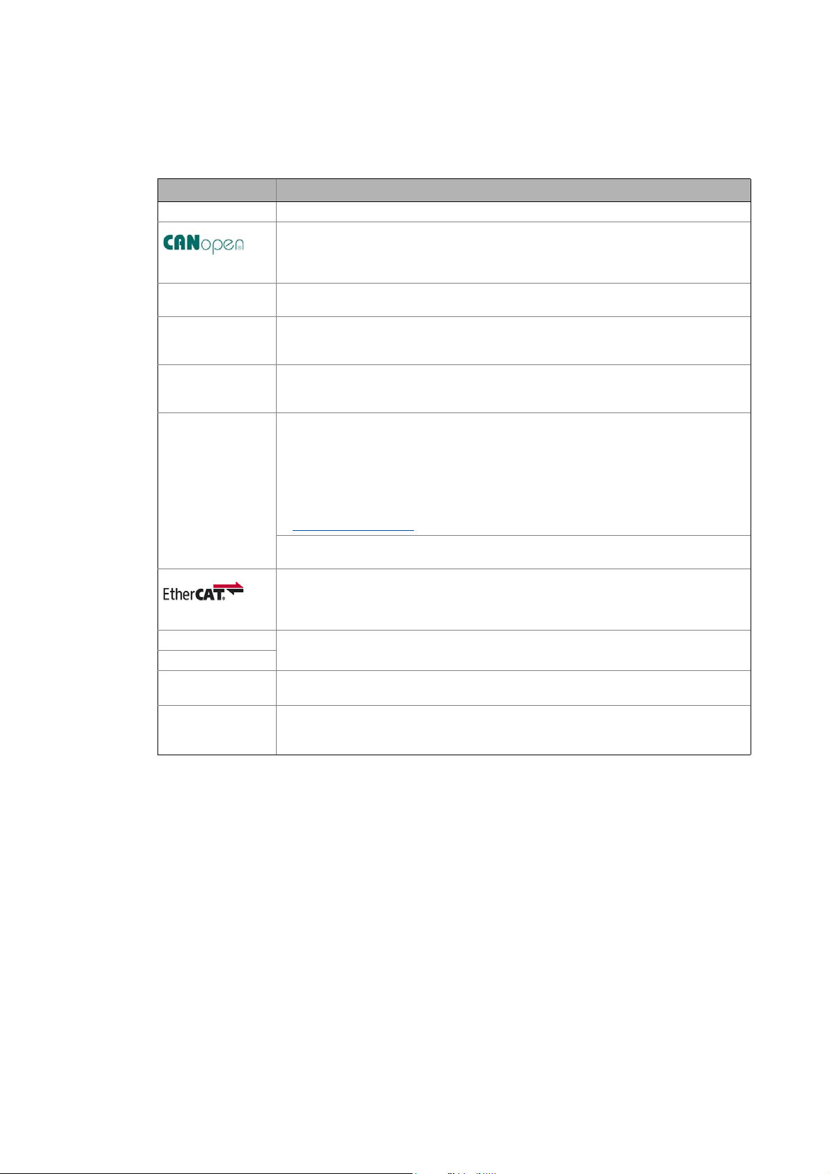
• is part of the "Controller-based Automation" manual collection. It consists of the following sets
of documentation:
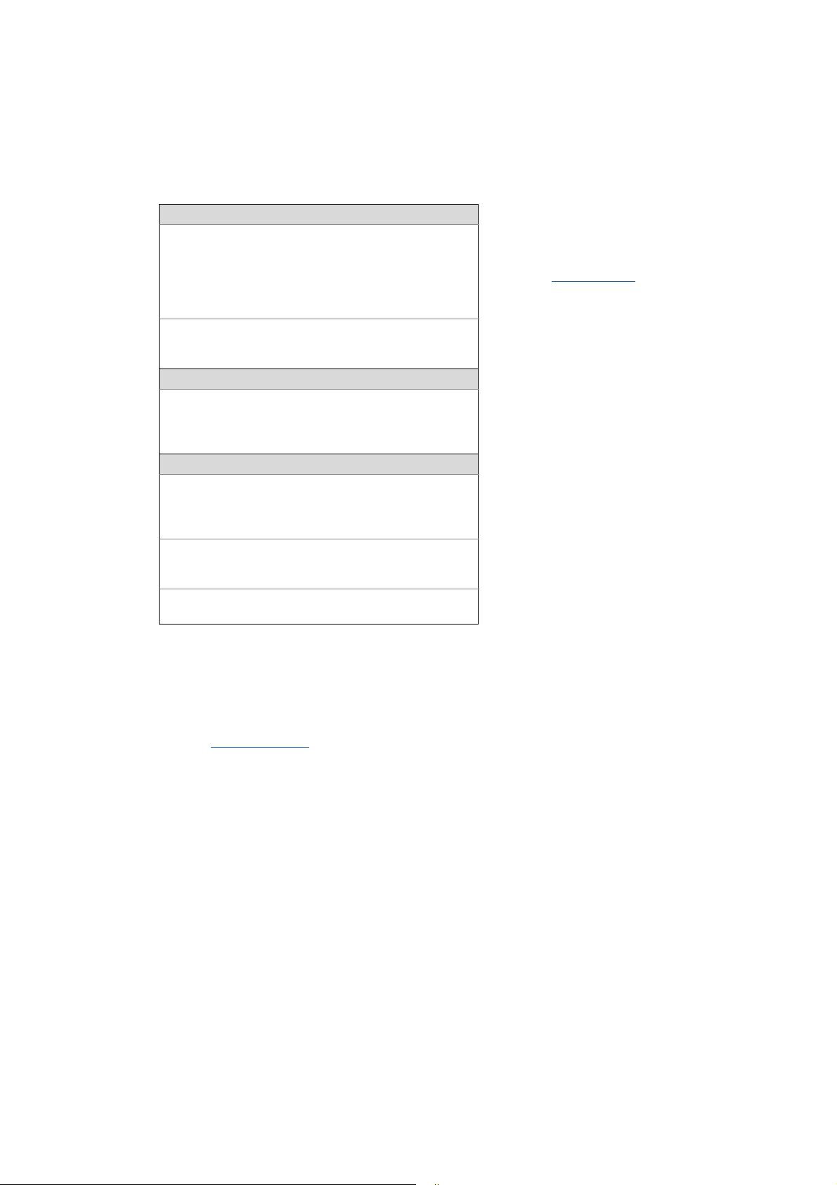
Documentation type Subject
System manuals System overview/sample topologies
• Controller-based Automation
• Visualising
Communication manuals
Online helps
Reference manuals
Online helps
Software manuals
Online helps
Bus systems
• Controller-based Automation EtherCAT®
• Controller-based Automation CANopen®
• Controller-based Automation PROFIBUS®
• Controller-based Automation PROFINET®
Lenze Controller:
• Controller 3200 C
• Controller c300
• Controller p300
• Controller p500
Lenze Engineering Tools:
• »PLC Designer«: Programming
• »Engineer«: Inverter configuration
• »VisiWinNET® Smart«: Visualisation
• »Backup & Restore«: Back up/restore data
5 Lenze · Controller-based Automation · CANopen® Communication Manual · DMS 6.3 EN · 04/2014 · TD17
Page 6
1 About this documentation
_ _ _ _ _ _ _ _ _ _ _ _ _ _ _ _ _ _ _ _ _ _ _ _ _ _ _ _ _ _ _ _ _ _ _ _ _ _ _ _ _ _ _ _ _ _ _ _ _ _ _ _ _ _ _ _ _ _ _ _ _ _ _ _
More technical documentation for Lenze components
Further information on Lenze products which can be used in conjunction with Controller-based
Automation can be found in the following sets of documentation:
Mounting & wiring Symbols:
Mounting instructions
• Controller
• Communication cards (MC-xxx)
• I/O system 1000 (EPM-Sxxx)
• Inverter, Servo Drives
•Communication modules
Operating instructions
• Controller
• Servo system ECS (ECSxE, ECSxM)
Sample applications/Using application templates
Online help/software manuals
• Application Sample i700
• Application Samples
• ApplicationTemplate
Parameter setting, configuration, commissioning
Online help/reference manuals
•L-force Controller
• Inverter, Servo Drives
• I/O system 1000 (EPM-Sxxx)
Online help/communication manuals
• Bus systems
•Communication modules
Operating instructions
• Servo system ECS (ECSxE, ECSxM)
Printed documentation
Online help in the Lenze Engineering
Tool (also available as PDF file at
www.lenze.com
.)
Tip!
Current documentation and software updates with regard to Lenze products can be found
in the download area at:
www.lenze.com
Target group
This documentation is intended for persons who plan, install, commission and maintain the
networking of devices as part of the Lenze automation system "Controller-based Automation".
Information on validity
The information provided in this documentation is valid for the Lenze automation system
"Controller-based Automation" from version 3.
Screenshots/application examples
All screenshots in this documentation are application examples. Depending on the firmware
version of the field devices and the software version of the Engineering tools installed (e.g. »PLC
Designer« ), screenshots in this documentation may differ from the representation on the screen.
Lenze · Controller-based Automation · CANopen® Communication Manual · DMS 6.3 EN · 04/2014 · TD17 6
Page 7
1 About this documentation
1.1 Document history
_ _ _ _ _ _ _ _ _ _ _ _ _ _ _ _ _ _ _ _ _ _ _ _ _ _ _ _ _ _ _ _ _ _ _ _ _ _ _ _ _ _ _ _ _ _ _ _ _ _ _ _ _ _ _ _ _ _ _ _ _ _ _ _
1.1 Document history
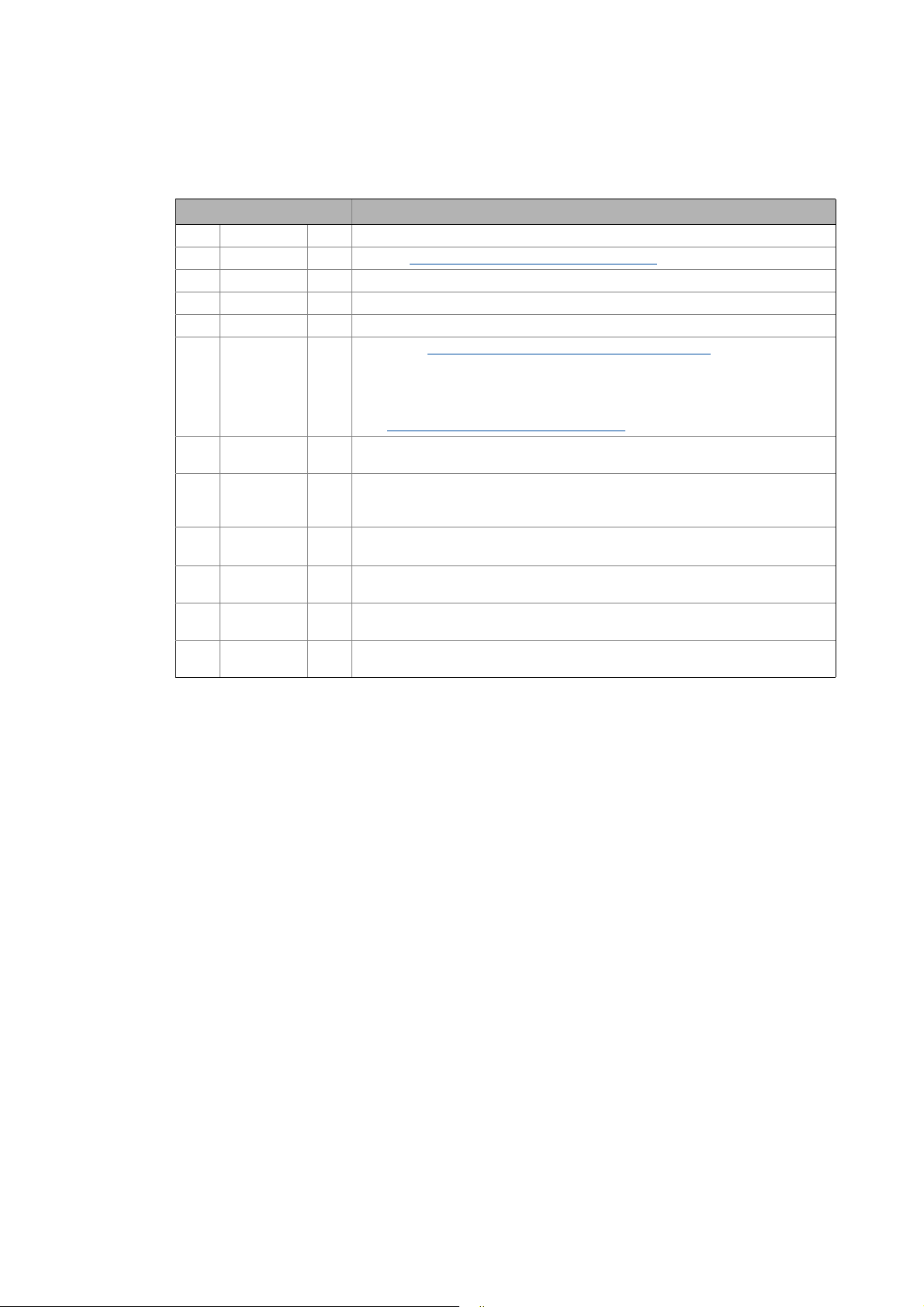
Version Description
1.0 06/2008 TD17 First edition
2.0 09/2008 TD17 Chapter "Mixed operation of CANopen and EtherCAT
3.0 06/2009 TD17 General revision
4.0 10/2009 TD17 General revision
5.0 10/2010 TD17 Commissioning and configuration with the Lenze »PLC Designer« V3.x
5.1 03/2011 TD17 • Chapter "Parallel operation of two synchronised CAN buses
5.2 12/2011 TD17 Revision on the Lenze automation system"Controller-based Automation",
5.3 07/2012 TD17 • Revision on the Lenze automation system"Controller-based Automation",
6.0 11/2012 TD17 • General corrections
6.1 03/2013 TD17 Revision on the Lenze automation system"Controller-based Automation",
6.2 11/2013 TD17 Revision on the Lenze automation system"Controller-based Automation",
6.3 04/2014 TD17 Revision on the Lenze automation system"Controller-based Automation",
supplemented.
• SoftMotion settings for Servo Drives 9400 and ECSxM supplemented.
• References to Lenze sample projects for CANopen Logic field devices (device
application + PLC program) added.
Commissioning of the CANopen Logic bus
release 3.2
release 3.3
• Information on the ECS servo system and »GDC« removed.
•New layout
release 3.5
release 3.6
release 3.8
" ( 92) added.
" ( 82)
( 36)
7
Lenze · Controller-based Automation · CANopen® Communication Manual · DMS 6.3 EN · 04/2014 · TD17
Page 8
1 About this documentation
1.2 Conventions used
_ _ _ _ _ _ _ _ _ _ _ _ _ _ _ _ _ _ _ _ _ _ _ _ _ _ _ _ _ _ _ _ _ _ _ _ _ _ _ _ _ _ _ _ _ _ _ _ _ _ _ _ _ _ _ _ _ _ _ _ _ _ _ _
1.2 Conventions used
This documentation uses the following conventions to distinguish different types of information:
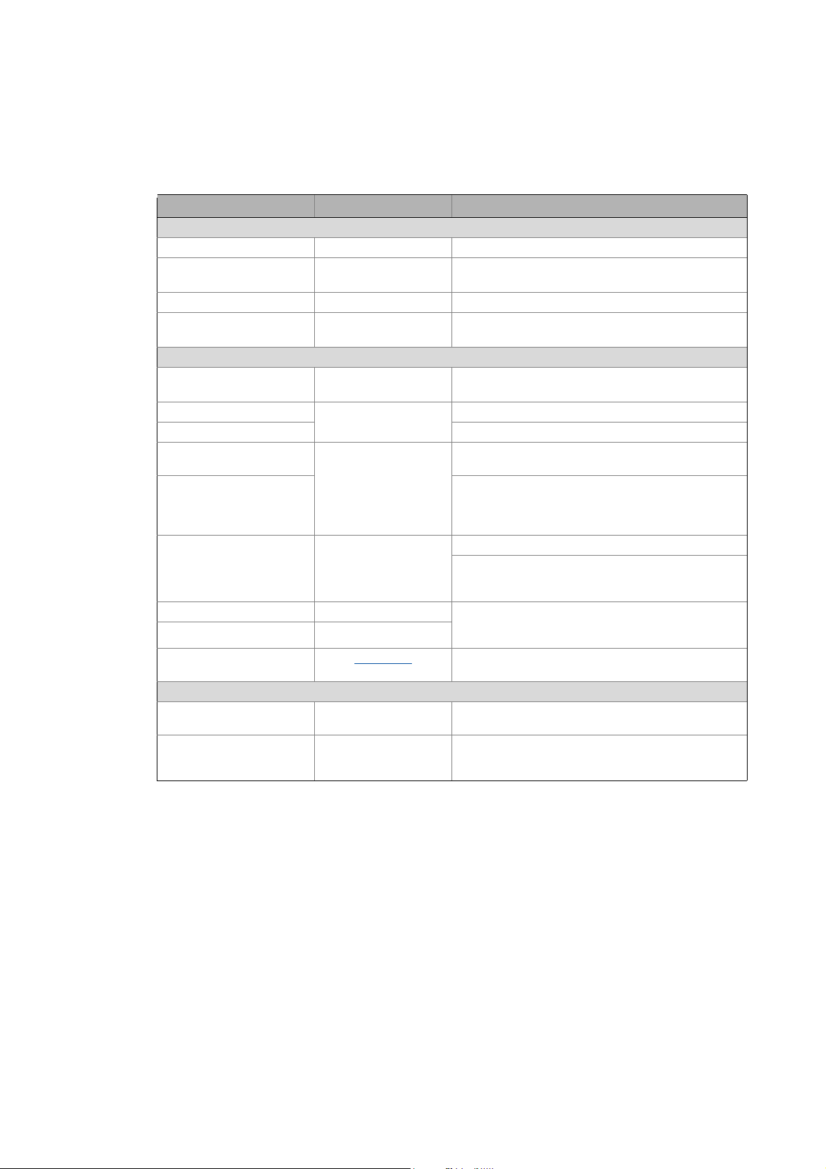
Type of information Identification Examples/notes
Numbers
Decimal Normal spelling Example: 1234
Decimal separator Point In general, the decimal point is used.
Example: 1234.56
Hexadecimal 0x[0 ... 9, A ... F] Example: 0x60F4
Binary
• Nibble
Text
Program name » « PC software
Window italics The message window... / The Options dialog box ...
Variable name Setting bEnable to TRUE...
Control element Bold The OK button ... / The Copy command ... / The Properties
Sequence of menu
commands
Shortcut <Bold> Use <F1> to open the online help.
Program code Courier IF var1 < var2 THEN
Keyword Courier bold
Hyperlink Underlined
Icons
Page reference ( 8) Optically highlighted reference to another page. Can be
Step-by-step instructions
0b[0, 1] Example: ’0b0110’
Example: ’0b0110.0100’
Example: Lenze »Engineer«
tab ... / The Name input field ...
If several successive commands are required for
executing a function, the individual commands are
separated from each other by an arrow: Select the
command File
If a key combination is required for a command, a "+" is
placed between the key identifiers: With
<Shift>+<ESC>...
a = a + 1
END IF
Optically highlighted reference to another topic. Can be
activated with a mouse-click in this documentation.
activated with a mouse-click in this documentation.
Step-by-step instructions are marked by a pictograph.
Open to...
Lenze · Controller-based Automation · CANopen® Communication Manual · DMS 6.3 EN · 04/2014 · TD17 8
Page 9
1 About this documentation
1.3 Terminology used
_ _ _ _ _ _ _ _ _ _ _ _ _ _ _ _ _ _ _ _ _ _ _ _ _ _ _ _ _ _ _ _ _ _ _ _ _ _ _ _ _ _ _ _ _ _ _ _ _ _ _ _ _ _ _ _ _ _ _ _ _ _ _ _
1.3 Terminology used
Term Meaning
CAN CAN (Controller Area Network) is an asynchronous, serial fieldbus system.
CANopen® is a communication protocol based on CAN. The Lenze system bus (CAN on board)
operates with a subset of this communication protocol.
CANopen® is a registered Community Trade Mark of the CAN User Organisation CiA® (CAN
in Automation e. V.).
Code Parameter for parameterising or monitoring the field device. The term is also referred to as
Controller The controller is the central component of the automation system which controls the Logic
Engineering PC The Engineering PC and the Engineering tools installed serve to configure and parameterise
Engineering tools Lenze software solutions for simply engineering in all phases:
Fieldbus stations Lenze Controller and controller integrated into the bus system (CANopen)
Field device
PLC Programmable Logic Controller
Subcode If a code contains several parameters, they are stored in so-called "subcodes".
"index" in common usage.
and Motion functionalities (by means of the runtime software).
The controller communicates with the field devices via the fieldbus.
the system.
The Engineering PC communicates with the controller via Ethernet.
•»EASY Starter«
• »Engineer«
•»PLC Designer«
•»WebConfig«
•»VisiWinNET®«
•»IPC Backup & Restore«
Lenze Engineering tools
»PCAN view« is the basic version of the »PCAN explorer« program by PEAK System Technik
GmbH for the diagnostics of CAN networks.
EtherCAT® (Ethernet for Controller and Automation Technology) is an Ethernet-based
fieldbus system which meets the application profile for industrial real-time systems.
EtherCAT® is a registered trademark and patented technology, licensed by Beckhoff
Automation GmbH, Germany.
(German designation: SPS - Speicherprogrammierbare Steuerung)
This manual uses a slash "/" as a separator between code and subcode (e.g. "C00118/3").
In normal usage, the term is also referred to as "Subindex".
( 19)
9
Lenze · Controller-based Automation · CANopen® Communication Manual · DMS 6.3 EN · 04/2014 · TD17
Page 10
1 About this documentation
1.4 Definition of the notes used
_ _ _ _ _ _ _ _ _ _ _ _ _ _ _ _ _ _ _ _ _ _ _ _ _ _ _ _ _ _ _ _ _ _ _ _ _ _ _ _ _ _ _ _ _ _ _ _ _ _ _ _ _ _ _ _ _ _ _ _ _ _ _ _
1.4 Definition of the notes used
The following signal words and symbols are used in this documentation to indicate dangers and
important information:
Safety instructions
Layout of the safety instructions:
Pictograph and signal word!
(characterises the type and severity of danger)
Note
(describes the danger and suggests how to prevent dangerous situations)
Pictograph Signal word Meaning
Danger! Danger of personal injury through dangerous electrical voltage
Danger! Danger of personal injury through a general source of danger
Stop! Danger of damage to material assets
Application notes
Refere nce to a n imm inent d ange r that m ay resu lt in de ath or s erious person al in jury
if the corresponding measures are not taken.
Refere nce to a n imm inent d ange r that m ay resu lt in de ath or s erious person al in jury
if the corresponding measures are not taken.
Reference to a possible danger that may result in damage to material assets if the
corresponding measures are not taken.
Pictograph Signal word Meaning
Note! Important note to ensure trouble-free operation
Tip! Useful tip for easy handling
Reference to other documentation
Lenze · Controller-based Automation · CANopen® Communication Manual · DMS 6.3 EN · 04/2014 · TD17 10
Page 11

2 Safety instructions
_ _ _ _ _ _ _ _ _ _ _ _ _ _ _ _ _ _ _ _ _ _ _ _ _ _ _ _ _ _ _ _ _ _ _ _ _ _ _ _ _ _ _ _ _ _ _ _ _ _ _ _ _ _ _ _ _ _ _ _ _ _ _ _
2 Safety instructions
Observe the following safety instructions if you want to commission an inverter or a system with
the Lenze Controller.
Read the documentation supplied with the system components carefully before you
start commissioning the devices and the Lenze Controller!
The system manual contains safety instructions which must be observed!
Danger!
Risk of injury
There is risk of injury by ...
• unpredictable motor movements (e.g. an unintended direction of rotation, too high
speeds, or jerky movement);
• impermissible operating states during the parameterisation while there is an active
online connection to the device.
Possible consequences
Death or severe injuries
Protective measures
• If required, provide systems with installed inverters with additional monitoring and
protective devices according to the safety regulations valid in each case (e.g. law on
technical equipment, regulations for the prevention of accidents).
• During commissioning, maintain an adequate safety distance to the motor or the
machine parts driven by the motor.
Stop!
Damage or destruction of machine parts
Damage or destruction of machine parts can be caused by ...
• unpredictable motor movements (e.g. an unintended direction of rotation, too high
speeds, or jerky movement);
• impermissible operating states during the parameterisation while there is an active
online connection to the device.
Possible consequences
Damage or destruction of machine parts
Protective measures
If required, provide systems with installed inverters with additional monitoring and
protective devices according to the safety regulations valid in each case (e.g. law on
technical equipment, regulations for the prevention of accidents).
11 Lenze · Controller-based Automation · CANopen® Communication Manual · DMS 6.3 EN · 04/2014 · TD17
Page 12
3 Controller-based Automation: Central motion control
_ _ _ _ _ _ _ _ _ _ _ _ _ _ _ _ _ _ _ _ _ _ _ _ _ _ _ _ _ _ _ _ _ _ _ _ _ _ _ _ _ _ _ _ _ _ _ _ _ _ _ _ _ _ _ _ _ _ _ _ _ _ _ _
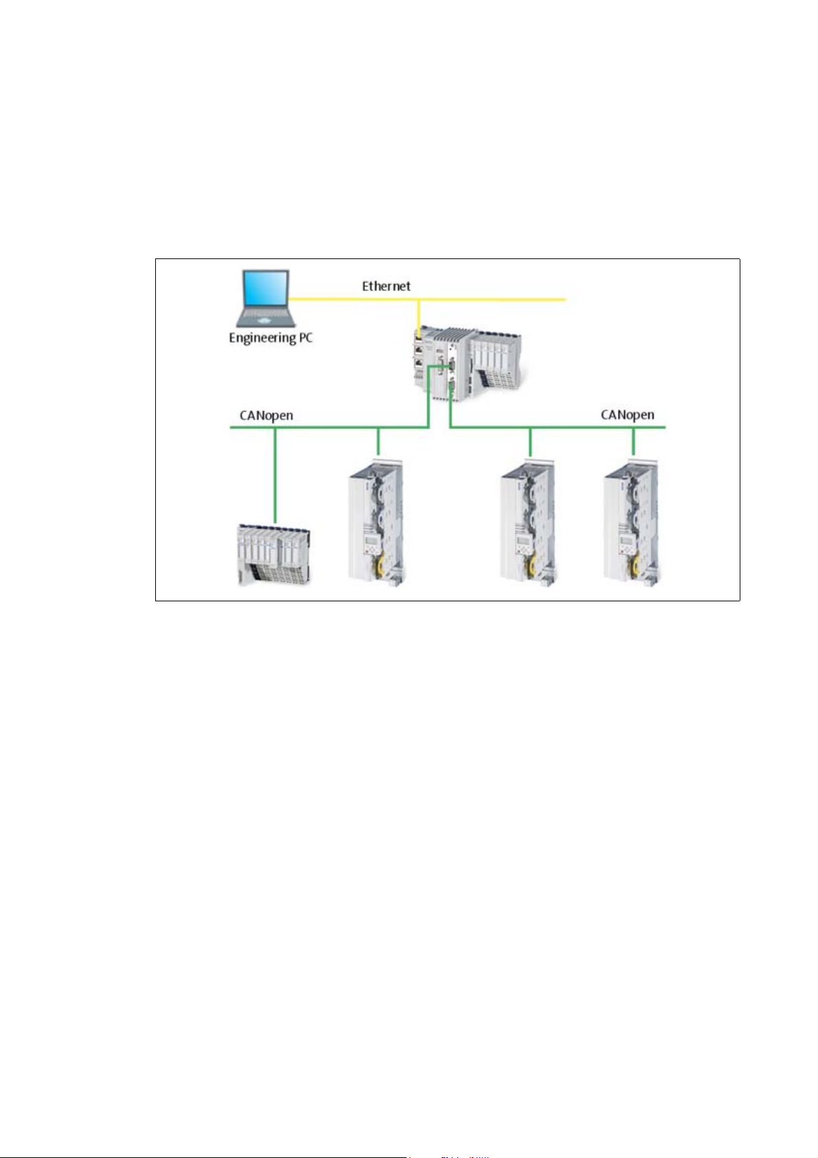
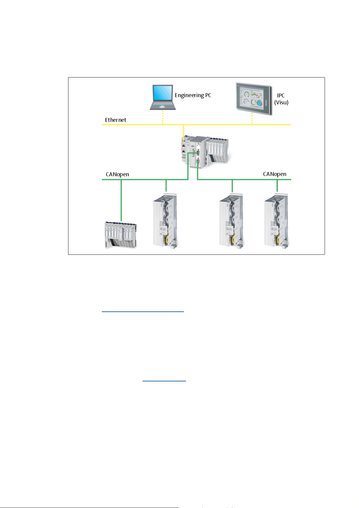
3 Controller-based Automation: Central motion control
The Lenze automation system "Controller-based Automation" serves to create complex automation
solutions with central motion control. Here, the Controller is the control centre of the system.
System structure of the Controller-based Automation: "All from one single source"
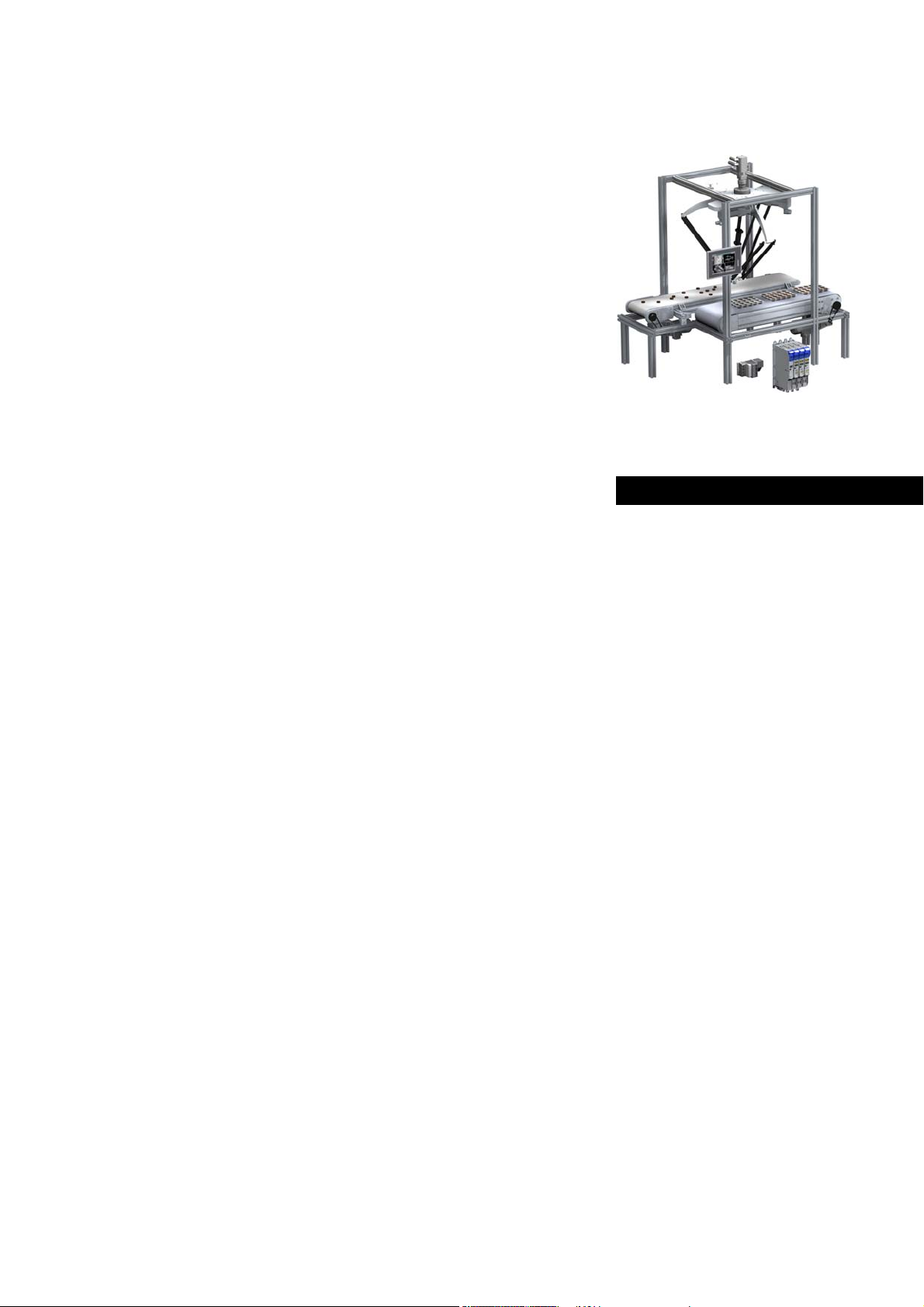
[3-1] Example: CANopen with the 3231 C Lenze Controller (I/O system 1000 and Servo Drive 9400 as slaves)
Lenze · Controller-based Automation · CANopen® Communication Manual · DMS 6.3 EN · 04/2014 · TD17 12
Page 13

3 Controller-based Automation: Central motion control
_ _ _ _ _ _ _ _ _ _ _ _ _ _ _ _ _ _ _ _ _ _ _ _ _ _ _ _ _ _ _ _ _ _ _ _ _ _ _ _ _ _ _ _ _ _ _ _ _ _ _ _ _ _ _ _ _ _ _ _ _ _ _ _
Lenze provides especially coordinated system components:
• Engineering software
The Lenze Engineering tools
to parameterise, configure and diagnose the system. The Engineering PC communicates with
the Controller via Ethernet.
•Controller
The Lenze Controller is available as Panel Controller with integrated touch display and as
Cabinet Controller in control cabinet design.
Cabinet Controllers provide a direct coupling of the I/O system 100 via the integrated backplane
bus.
The runtime software of the Lenze Controllers provides the control and/or visualisation of
motion sequences. The following software versions are available:
• "Logic": Sequence control in the Controller, motion control in the inverter
• "Motion": Sequence control and motion control in the Controller, inverter as actuating drive
• "Visu": Optional visualisation of the automation system, can be used separately or in addition
to "Logic" or "Motion"
An external monitor panel/display can be connected to the Cabinet Controller 3231 C/
3241 C.
• Without software: Controller as single component with operating system only
•Bus systems
EtherCAT is a standard "on board" bus system of the Controller-based Automation. EtherCAT
enables the control of all nodes (Motion/Logic) on one common fieldbus.
Optionally, CANopen, PROFIBUS and PROFINET can be used as extended topologies.
The Controllers c300/p300 have a CANopen interface "on board" as well (in addition to
EtherCAT).
• Inverter (e.g. Servo Inverter i700)
( 19) on your Engineering PC (Windows operating system ) serve
"Logic & Motion" runtime software
The "Controller-based Automation" system allows for the central control of devices for Logic and
Motion applications. The runtime software runs on the Controller.
In case of Logic applications, the sequence control is carried out in the Controller and the motion
control is carried out in the inverter.
In case of Motion applications , the sequence control and motion control are carried out in the
Controller. The inverter is used as actuating drive.
• Motion applications make special demands on the cycle time and real-time capability of the bus
system between the Controller and the subordinate fieldbus nodes.
• this is for instance the case if the field devices, for example, are to move in a synchronised way
or if position setpoints are to be transmitted.
13 Lenze · Controller-based Automation · CANopen® Communication Manual · DMS 6.3 EN · 04/2014 · TD17
Page 14
3 Controller-based Automation: Central motion control
_ _ _ _ _ _ _ _ _ _ _ _ _ _ _ _ _ _ _ _ _ _ _ _ _ _ _ _ _ _ _ _ _ _ _ _ _ _ _ _ _ _ _ _ _ _ _ _ _ _ _ _ _ _ _ _ _ _ _ _ _ _ _ _
Fieldbus communication
The Lenze Controllers have different interfaces for fieldbus communication:
Area Cabinet Controller Panel Controller
c300 3221 C 3231 C 3241 C p300 p500
Interfaces (on board)
Ethernet1212
EtherCAT 1
CANopen 1
Optional interfaces (communication cards)
CANopen
MC-CAN2
PROFIBUS master
MC-PBM
PROFIBUS slave
MC-PBS
PROFINET device
MC-PND
1)
2)
- -
- -
- -
- -
11
-1
1)
2)
1
-
1) In preparation
2) Only the CAN master functionality is supported.
The Ethernet interface serves to connect the Engineering PC or to create line topologies (no
integrated switch for Controller c300/p300).
More information on the bus systems and configuration can be found in the
communication manuals:
• Controller-based Automation EtherCAT®
• Controller-based Automation CANopen®
• Controller-based Automation PROFIBUS®
• Controller-based Automation PROFINET®
Lenze · Controller-based Automation · CANopen® Communication Manual · DMS 6.3 EN · 04/2014 · TD17 14
Page 15

4 System bus (CAN) / CANopen
_ _ _ _ _ _ _ _ _ _ _ _ _ _ _ _ _ _ _ _ _ _ _ _ _ _ _ _ _ _ _ _ _ _ _ _ _ _ _ _ _ _ _ _ _ _ _ _ _ _ _ _ _ _ _ _ _ _ _ _ _ _ _ _
4 System bus (CAN) / CANopen
The control technology based on CANopen allows for the integration of all Lenze device series
provided with the Lenze system bus (CAN on board).
In order to extend the existing limits of the CAN bus, several CAN lines synchronised with each other
can be used. The number of CAN lines available depends on the equipment of the Lenze Controller
in each case.
The maximum possible number of nodes on a CAN line depends on the baud rate and the cycle time
set.
Example: In the case of a cycle time of 1 ms and a baud rate of 1 Mbps, three nodes with a setpoint
PDO and an actual value PDO, respectively, can be actuated on the CAN bus.
Tip!
Detailed information on CAN/CANopen can be found on the website of the CAN User
Organization CiA (CAN in Automation):
www.can-cia.org
15 Lenze · Controller-based Automation · CANopen® Communication Manual · DMS 6.3 EN · 04/2014 · TD17
Page 16
4 System bus (CAN) / CANopen
4.1 CANopen (Logic) / CANopen (Motion)
_ _ _ _ _ _ _ _ _ _ _ _ _ _ _ _ _ _ _ _ _ _ _ _ _ _ _ _ _ _ _ _ _ _ _ _ _ _ _ _ _ _ _ _ _ _ _ _ _ _ _ _ _ _ _ _ _ _ _ _ _ _ _ _
4.1 CANopen (Logic) / CANopen (Motion)
[4-1] Example: CANopen (Logic/Motion) with the 3231 C controller (I/O system 1000 and Servo Drive 9400 as slaves)
Due to the requirements regarding the real time behaviour of the fieldbus system and due to its
limited transfer capacity, it is useful to operate Logic and Motion devices on separate CAN phases if
CANopen is used – on a logic bus and a motion bus.
The Lenze Controllers ...
•with the Communication card MC-CAN2
and CANopen (Motion);
• can also be used as CAN slaves.
Depending on the required number of Motion nodes and bus cycle time, up to 2 Motion bus lines
can be created.
( 18) have two CAN interfaces for CANopen (Logic)
Tip!
A sample project for operation of a 3200 C controller as CAN slave can be found in the
"Download" area at www.Lenze.com
"Application Knowledge Base": All articles Application Ideas Pool Controller 3200 C
:
Lenze · Controller-based Automation · CANopen® Communication Manual · DMS 6.3 EN · 04/2014 · TD17 16
Page 17

4 System bus (CAN) / CANopen
4.2 Field devices
_ _ _ _ _ _ _ _ _ _ _ _ _ _ _ _ _ _ _ _ _ _ _ _ _ _ _ _ _ _ _ _ _ _ _ _ _ _ _ _ _ _ _ _ _ _ _ _ _ _ _ _ _ _ _ _ _ _ _ _ _ _ _ _
4.2 Field devices
The Lenze automation system supports the following Logic/Motion components:
Field devices System bus (CAN/CANopen)
Logic Motion
Controller Controller 32xx C
Controller c300
Controller p300
Controller p500
Servo Drives 9400 HighLine 1)
HighLine with CiA402
PLC
Regenerative power supply
module
Inverter Drives 8400 BaseLine
StateLine
HighLine
TopLine
I/O-System 1000 EPM-Sxxx
1) with technology application (TA)
17
Lenze · Controller-based Automation · CANopen® Communication Manual · DMS 6.3 EN · 04/2014 · TD17
Page 18
4 System bus (CAN) / CANopen
4.3 CANopen hardware for Lenze Controllers
_ _ _ _ _ _ _ _ _ _ _ _ _ _ _ _ _ _ _ _ _ _ _ _ _ _ _ _ _ _ _ _ _ _ _ _ _ _ _ _ _ _ _ _ _ _ _ _ _ _ _ _ _ _ _ _ _ _ _ _ _ _ _ _
4.3 CANopen hardware for Lenze Controllers
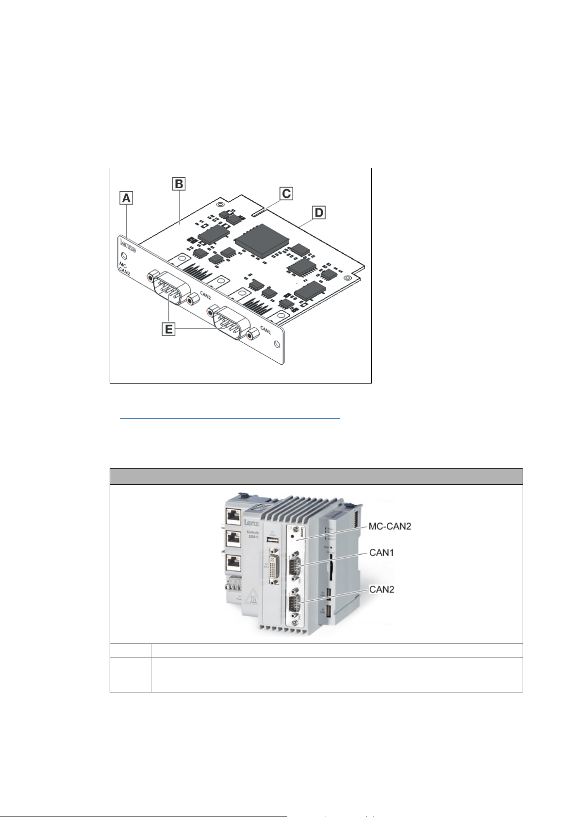
Communication card MC-CAN2
The MC-CAN2 communication card serves to connect a Lenze Controller to the CAN bus system. The
card provides two independent bus lines.
A Front panel
B Printed circuit board
C Coding
D Connection of Lenze Controller
E CAN connection
MC-CAN2-001
[4-2] Communication card MC-CAN2
Technical data of the MC-CAN2 communication card ( 21)
Use
The MC-CAN2 communication card is installed in the corresponding slot of the Lenze Controller.
Example: Lenze Controller 3231 C with MC-CAN2 communication card
MC-CAN2 Communication card MC-CAN2
CAN1
CAN2
Connections for the 2 bus lines
• CAN1: CANopen (Logic and/or Motion)
• CAN2: CANopen (Logic and/or Motion)
Lenze · Controller-based Automation · CANopen® Communication Manual · DMS 6.3 EN · 04/2014 · TD17 18
Page 19
4 System bus (CAN) / CANopen
4.4 Lenze Engineering tools
_ _ _ _ _ _ _ _ _ _ _ _ _ _ _ _ _ _ _ _ _ _ _ _ _ _ _ _ _ _ _ _ _ _ _ _ _ _ _ _ _ _ _ _ _ _ _ _ _ _ _ _ _ _ _ _ _ _ _ _ _ _ _ _
4.4 Lenze Engineering tools
The Lenze Engineering tools enable the configuration and operation of controller-based Lenze
automation systems according to individual requirements.
Use the corresponding Engineering tool applicable to the field device.
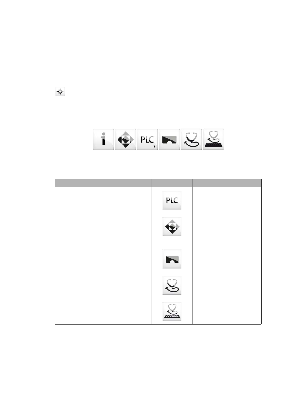
»EASY Navigator«
The »EASY Navigator« provides an overview of the Lenze Engineering software installed on the
Engineering PC.
The Lenze Engineering software consists of the Engineering tools optimised for the respective
application case.
The »EASY Navigator« ...
• simplifies orientation for selecting the suitable Engineering tool;
• allows for the simple start of the required Engineering tool (depending on the application):
What would you like to do? Button Engineering tool
Programming
• Parameterise the Lenze Controller
• Parameterise the i700 servo inverter
• Parameterise the I/O system 1000
Configuring the inverter
• Projecting the automation/drive system
• Parameterisation/configuration
• Inverter Drives 8400, 8400 motec/protec
• Servo Drives 9400
• I/O-System 1000
Visualising
• Visualising the automation system
• Creating the user interface
Online diagnostics
Easy online diagnostics of Lenze Controllers and
other Lenze field devices
»PLC Designer«
»Engineer«
»VisiWinNET«
»EASY Starter«
19
Online parameterisation
• Online parameterisation and commissioning
• Direct online parameterisation when the online
connection to the Lenze devices is active.
»EASY Starter«
Further Engineering tools that are not called via the »EASY Navigator« are:
• »WebConfig« (web-based parameterisation, configuration, and online diagnostics)
• »Backup & Restore« (data backup, data recovery).
Lenze · Controller-based Automation · CANopen® Communication Manual · DMS 6.3 EN · 04/2014 · TD17
Page 20

5Technical data
5.1 General data
_ _ _ _ _ _ _ _ _ _ _ _ _ _ _ _ _ _ _ _ _ _ _ _ _ _ _ _ _ _ _ _ _ _ _ _ _ _ _ _ _ _ _ _ _ _ _ _ _ _ _ _ _ _ _ _ _ _ _ _ _ _ _ _
5 Technical data
5.1 General data
Area Values
Communication profile CANopen (DS301, V4.02)
Standards CAN, ISO 11898 / EN 50325-4
Network topology Line, terminated at both ends with 120
(e.g. terminated with Sub-D plug of type EWZ0046)
Max. number of nodes 127
Adjustable node addresses 1 ... 127
(adjustable for Lenze devices via DIP switches)
Baud rates [kbps] • 10
•20
•50
• 125
• 250
• 500
• 1000
Parameter data Max. 10 client and server SDO channels with 1 ... 8 bytes
Cycle time - Motion/CNC task 1 ... 16 ms
Number of drives/ms on the Motion
bus
Signal propagation delay drive
controller drive
Cross communication Only possible with CANopen (Logic)
Number of DI + DO (bits/ms) 384 (max. 6 PDOs/ms on the Logic bus)
Cycle synchronisation with locked
PLL (Jitter)
Max. 3 drives/ms
4 cycles
In the case of CANopen (Motion), communication is executed centrally via
the Lenze Controller.
+/-10 μs
Lenze · Controller-based Automation · CANopen® Communication Manual · DMS 6.3 EN · 04/2014 · TD17 20
Page 21
5Technical data
5.2 Technical data of the MC-CAN2 communication card
_ _ _ _ _ _ _ _ _ _ _ _ _ _ _ _ _ _ _ _ _ _ _ _ _ _ _ _ _ _ _ _ _ _ _ _ _ _ _ _ _ _ _ _ _ _ _ _ _ _ _ _ _ _ _ _ _ _ _ _ _ _ _ _
5.2 Technical data of the MC-CAN2 communication card
Area Values
Type within the network Master or slave
Max. number of nodes 63
Max. baud rate 1000 kbps
Bus length See chapter "Bus cable length
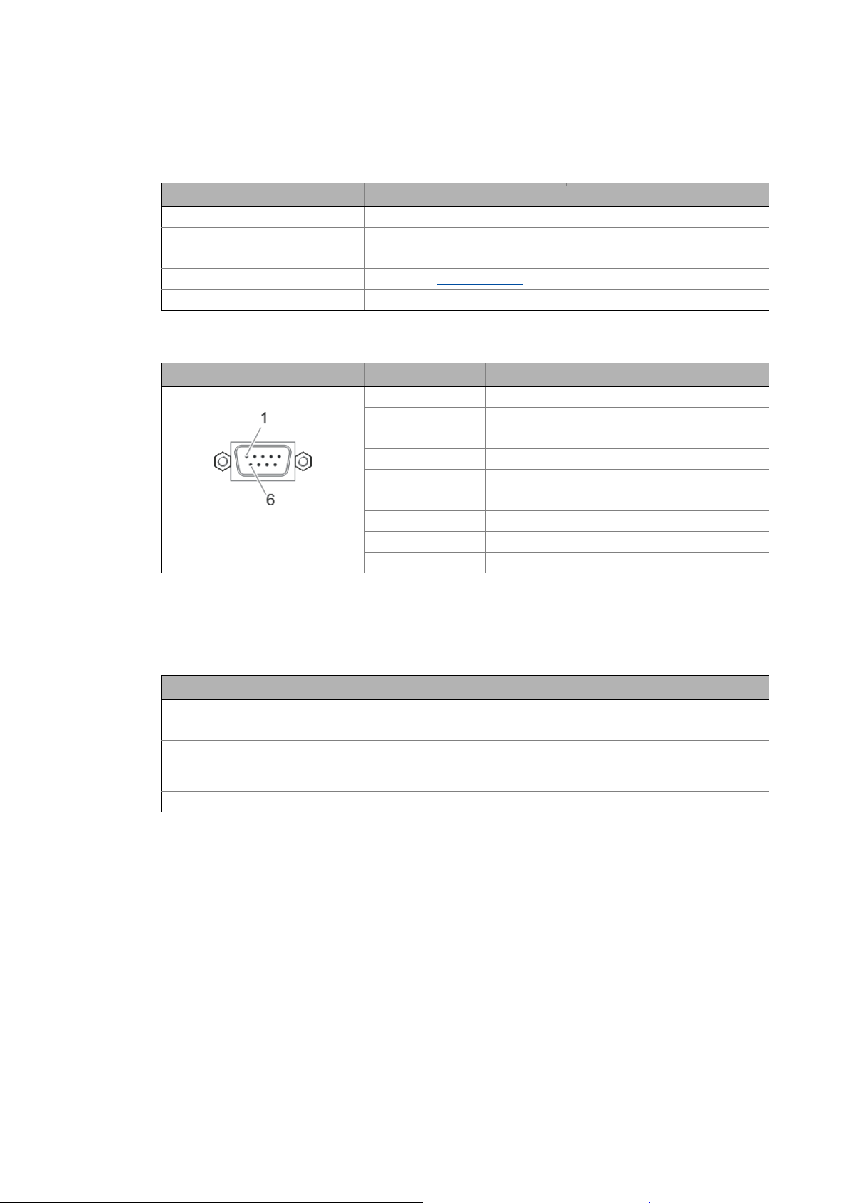
Connection SUB-D, 9-pole plug
Connection of CAN bus (SUB-D, 9-pole plug)
View Pin Assignment Description
1free -
2LO CAN-LOW
3CG CAN-Ground
4free -
5free -
6CG CAN-Ground
7HI CAN-HIGH
8free -
9free -
" ( 22)
5.3 Bus cable specification
We recommend to use CAN cables according to ISO 11898-2:
CAN cables according to ISO 11898-2
Cable type Paired cable with shield
Impedance 120 (95 ... 140 )
Cable resistance/cross-section
Cable length 301 ... 1000 m:
Signal propagation delay 5 ns/m
Cable length 300 m:
70 m/m / 0.25... 0.34 mm
40 m/m / 0.5 mm
2
(AWG20)
2
(AWG22)
21
Lenze · Controller-based Automation · CANopen® Communication Manual · DMS 6.3 EN · 04/2014 · TD17
Page 22
5Technical data
5.4 Bus cable length
_ _ _ _ _ _ _ _ _ _ _ _ _ _ _ _ _ _ _ _ _ _ _ _ _ _ _ _ _ _ _ _ _ _ _ _ _ _ _ _ _ _ _ _ _ _ _ _ _ _ _ _ _ _ _ _ _ _ _ _ _ _ _ _
5.4 Bus cable length
Note!
• It is absolutely necessary to comply with the permissible cable lengths.
• Observe the reduction of the total cable length due to the signal delay of the repeater.
Use of repeaters
• If the total cable lengths of the nodes are different at the same baud rate, the smaller
value must be used to determine the max. cable length.
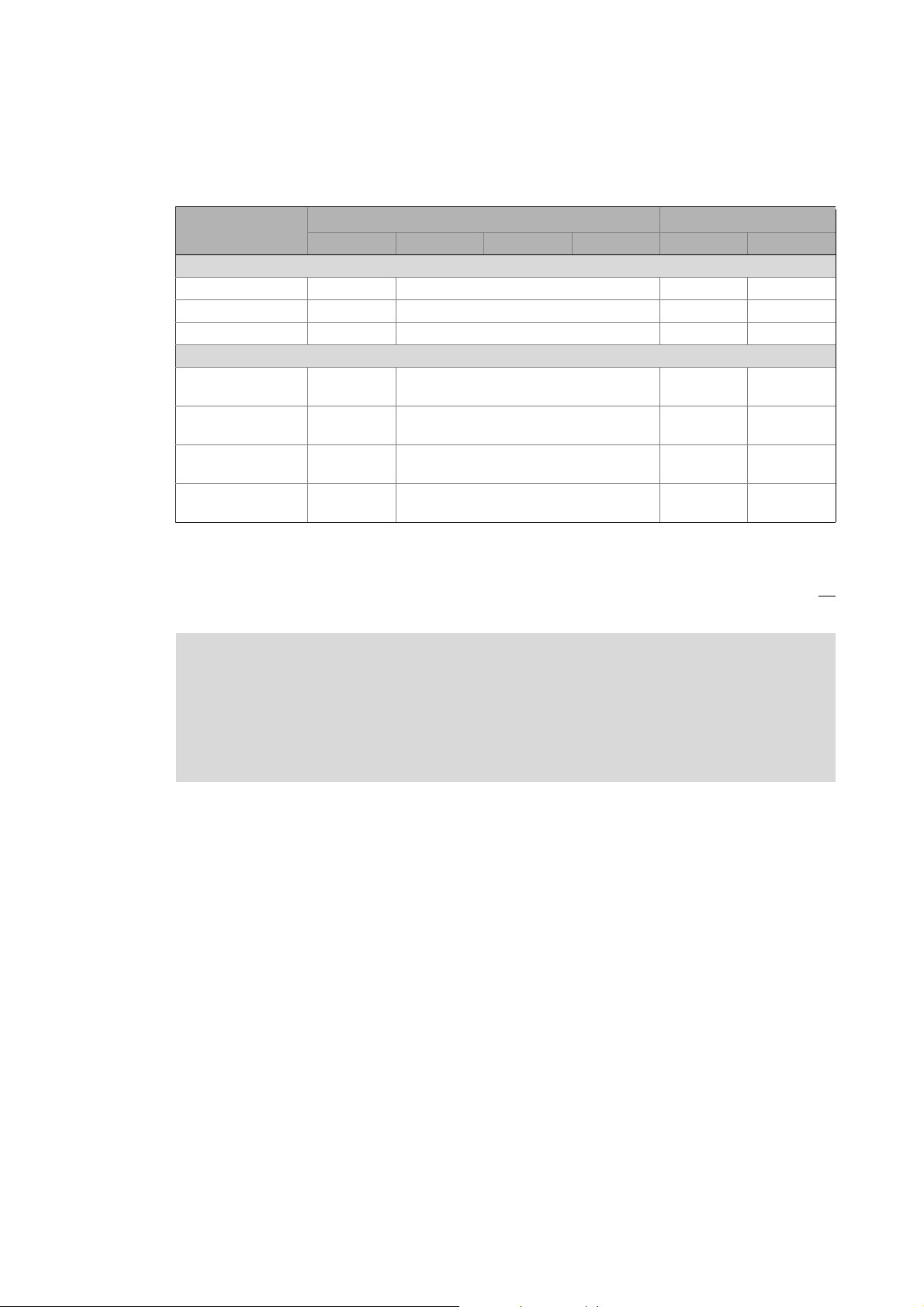
5.4.1 Total cable length
The total cable length is also specified by the baud rate.
Baud rate [kbps] Max. bus length [m]
10 8000 - 5000
20 4000 - 2500
50 1500 1500 1000
125 600 600 500
250 275 275 250
500 110 110 80
1000 13 13 25
( 23)
Servo Drives
9400
Inverter Drives
8400
I/O-System 1000
(EPM-Sxxx)
CANopen bus coupler
5.4.2 Segment cable length
Repeaters divide the total cable length into segments. The segment cable length is defined by the
cable cross-section and the number of nodes per segment. Without a repeater, the segment cable
length corresponds to the total cable length.
Max. number of
nodes per segment
2 240 m 430 m 650 m 940 m
5 230 m 420 m 640 m 920 m
10 230 m 410 m 620 m 900 m
20 210 m 390 m 580 m 850 m
32 200 m 360 m 550 m 800 m
63 170 m 310 m 470 m 690 m
100 150 m 270 m 410 m 600 m
Cable cross-section
0.25 mm
2
0.50 mm
2
0.75 mm
2
1.00 mm
2
Lenze · Controller-based Automation · CANopen® Communication Manual · DMS 6.3 EN · 04/2014 · TD17 22
Page 23

5Technical data
5.4 Bus cable length
_ _ _ _ _ _ _ _ _ _ _ _ _ _ _ _ _ _ _ _ _ _ _ _ _ _ _ _ _ _ _ _ _ _ _ _ _ _ _ _ _ _ _ _ _ _ _ _ _ _ _ _ _ _ _ _ _ _ _ _ _ _ _ _
5.4.3 Use of repeaters
Compare the values from the tables Total cable length ( 22) and Segment cable length ( 22).
If the detected segment cable length is smaller than the total cable length to be achieved, repeaters
must be used.
Example: Detecting cable lengths / number of repeaters
Given:
Cable cross-section 0.5 mm
Number of nodes 127
Repeater Lenze repeater, type 2176 (cable reduction: 30 m)
At the maximum number of nodes (127), the following cable lengths/number of repeaters from the
specifications have to be observed:
Baud rate [kbps] 10 20 50 125 250 500 800 1000
Max. cable length [m] 8000 3900 1500 630 290 110 40 17
Segment cable length [m] 270 270 270 270 270 110 40 17
Number of repeaters 33 16 6 2 1 - - -
2
, according to Bus cable specification ( 21)
23
Lenze · Controller-based Automation · CANopen® Communication Manual · DMS 6.3 EN · 04/2014 · TD17
Page 24
5Technical data
5.4 Bus cable length
_ _ _ _ _ _ _ _ _ _ _ _ _ _ _ _ _ _ _ _ _ _ _ _ _ _ _ _ _ _ _ _ _ _ _ _ _ _ _ _ _ _ _ _ _ _ _ _ _ _ _ _ _ _ _ _ _ _ _ _ _ _ _ _
Example: Check use of repeater
Given:
Baud rate 125 kbps
Cable cross-section 0.5 mm
Number of nodes 28
Cable length 450 m
Test step Cable length See table ...
1 Total cable length at 125 kbps: 630 m Total cable length
2 Segment cable length for 28 nodes and a cable cross-
section of 0.5 mm
3 Comparison: The detected segment cable length is
smaller than the total cable length of 450 m to be
achieved.
2
:
Conclusion:
• It is not possible to use a cable length of 450 m without using a repeater.
• After 360 m (test step 2) a repeater has to be used.
2
( 22)
360 m Segment cable length
( 22)
Result:
• The Lenze repeater, type 2176 (cable reduction: 30 m), is used
•Calculation of the maximum cable length:
• First segment: 360 m
• Second segment: 360 m (see table Segment cable length
for a repeater)
• Max. achievable cable length with a repeater: 690 m
• The selected cable length can be implemented.
( 22)) minus 30 m (cable reduction
Lenze · Controller-based Automation · CANopen® Communication Manual · DMS 6.3 EN · 04/2014 · TD17 24
Page 25
6 Planning the CANopen network
_ _ _ _ _ _ _ _ _ _ _ _ _ _ _ _ _ _ _ _ _ _ _ _ _ _ _ _ _ _ _ _ _ _ _ _ _ _ _ _ _ _ _ _ _ _ _ _ _ _ _ _ _ _ _ _ _ _ _ _ _ _ _ _
6 Planning the CANopen network
Create an overview screen of the planned CANopen network with all field devices to be
implemented. Start with the Lenze Controller and arrange the other field devices below it (see
Example of an overview screen
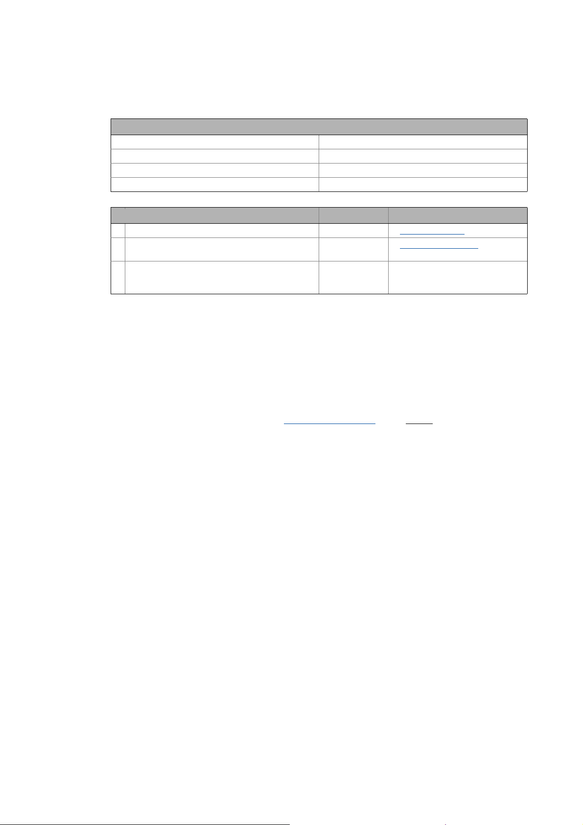
Provide the following data for each device:
Type Type designation of the field device
Used CAN interface of the device • The functionality of the two available CAN interfaces is identical. Both
Unambiguous CAN node address • If system bus (CAN) devices are used, max. 63 nodes/node addresses are
Baud rate • The baud rate applies to all nodes of the CANopen network.
Master task of the device
(NMT master/Sync master)
CAN objects and COB-IDs • Plan your COB-IDs according to the CANopen DS301 communication
( 27)).
Logic and Motion devices can be connected. The combination of Logic and
Motion on an interface is possible as well.
• If possible, the Logic and Motion devices should be installed on different
CAN lines:
• The requirements of the Motion devices regarding the synchronicity of
the bus are higher.
• Shorter cycle times are needed.
• The data volume to be transferred is larger.
CANopen (Logic) / CANopen (Motion)
possible.
• With CANopen-compliant devices, up to 127 nodes/node addresses are
possible.
Note: Do not use the node address 1, in order to avoid unintentional
mistakes and conflicts with a device containing the factory adjustment.
• 50, 125, 250 and 500 kbps are supported by all device types of the system.
• Observe the connection between bus cable length and baud rate.Bus
cable length ( 22)
•An NMT master sets itself and then the NMT slaves to the "Operational"
state. In this state, process data can be communicated. Generally, there
can be an optional number of NMT masters on one CANopen bus.
•A Sync master cyclically sends a sync telegram providing for an exactly
simultaneous processing of process data and/or a simultaneous task
start in all sync receivers.
• Via CAN synchronisation, the Lenze Controller can influence the exact
time of the following events in the field device:
• Acceptance and transmission of sync-controlled PDOs
• Starting time of the task of the application (only possible in 9400)
• You only need to use CAN synchronisation on the Logic bus if an exact
simultaneity in the range of milliseconds is of importance. A mere
operating periphery (operator button, control lamps, etc.) does not
require CAN synchronisation.
profile. This convention is optimised for the communication with a
central master device.COB-IDs acc. to DS301
• Up to 4 PDOs per device can be identif ied with this sch eme. I f you require
more, e.g. for a modular I/O system with more than 8 modules, you can
add them later.
• You can easily assign the node during the bus diagnostics by means of the
COB-IDs.
• COB-ID = basic identifier + node address
( 16)
( 26)
25 Lenze · Controller-based Automation · CANopen® Communication Manual · DMS 6.3 EN · 04/2014 · TD17
Page 26

6 Planning the CANopen network
6.1 COB-IDs acc. to DS301
_ _ _ _ _ _ _ _ _ _ _ _ _ _ _ _ _ _ _ _ _ _ _ _ _ _ _ _ _ _ _ _ _ _ _ _ _ _ _ _ _ _ _ _ _ _ _ _ _ _ _ _ _ _ _ _ _ _ _ _ _ _ _ _
Please observe ...
the device-specific information on the CAN configuration in the documentation for the
field devices to be implemented.
6.1 COB-IDs acc. to DS301
Object Direction Basic identifier
from the drive to the drive Dec hex
NMT 0 0x000
Sync 128 0x080
Time Stamp 256 0x100
Emergency 128 0x080
PDO1
(Process data channel 1)
PDO2
(Process data channel 2)
PDO3
(Process data channel 3)
PDO4
(Process data channel 4)
SDO
(Parameter data channel 1)
NMT Error Control 1792 0x700
TPDO1
RPDO1
TPDO2
RPDO2
TPDO3
RPDO3
TPDO4
RPDO4
384 0x180
512 0x200
640 0x280
768 0x300
896 0x380
1024 0x400
1152 0x480
1280 0x500
1408 0x580
1536 0x600
Note!
In Lenze system bus (CAN) devices, two SDO channels are permanently active, in
CANopen devices, only one by default.
When using CANopen devices, activate a second SDO channel for access of the
»Engineer«. Otherwise communication with the device will be interfered if you go online
with the »Engineer« while the Lenze Controller has access as well.
The COB-IDs for your CANopen network can be calculated according to the following formula:
COB-ID = basic identifier + node address
Basic identifier - 9400 Servo Drives
Basic identifier - 8400 Inverter Drives
Basic identifier - I/O system 1000 (EPM-Sxxx)
( 29)
( 30)
( 31)
Lenze · Controller-based Automation · CANopen® Communication Manual · DMS 6.3 EN · 04/2014 · TD17 26
Page 27
6 Planning the CANopen network
6.2 Example of an overview screen
_ _ _ _ _ _ _ _ _ _ _ _ _ _ _ _ _ _ _ _ _ _ _ _ _ _ _ _ _ _ _ _ _ _ _ _ _ _ _ _ _ _ _ _ _ _ _ _ _ _ _ _ _ _ _ _ _ _ _ _ _ _ _ _
6.2 Example of an overview screen
The illustration shows you an example of an overview screen for planning a CANopen network:
[6-1] Example of an overview screen for designing a CANopen network
27
Lenze · Controller-based Automation · CANopen® Communication Manual · DMS 6.3 EN · 04/2014 · TD17
Page 28

6 Planning the CANopen network
6.3 Device specifications of the field devices
_ _ _ _ _ _ _ _ _ _ _ _ _ _ _ _ _ _ _ _ _ _ _ _ _ _ _ _ _ _ _ _ _ _ _ _ _ _ _ _ _ _ _ _ _ _ _ _ _ _ _ _ _ _ _ _ _ _ _ _ _ _ _ _
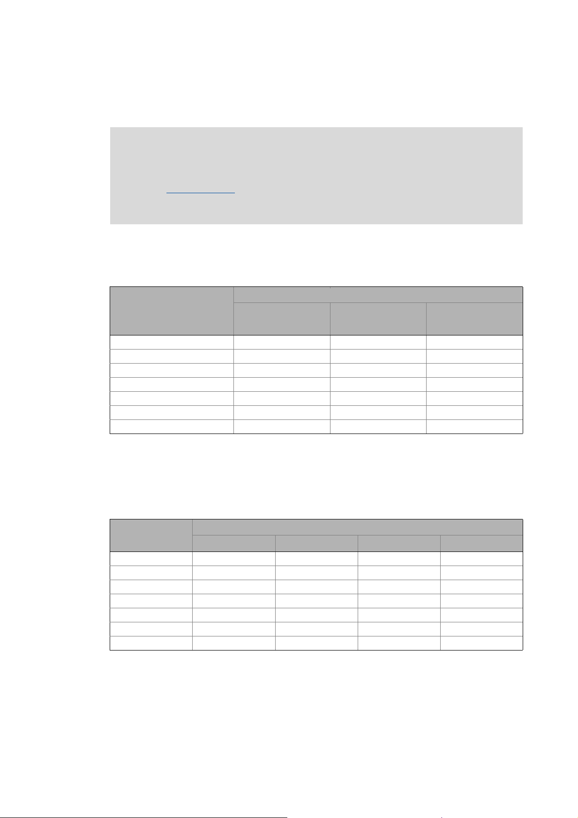
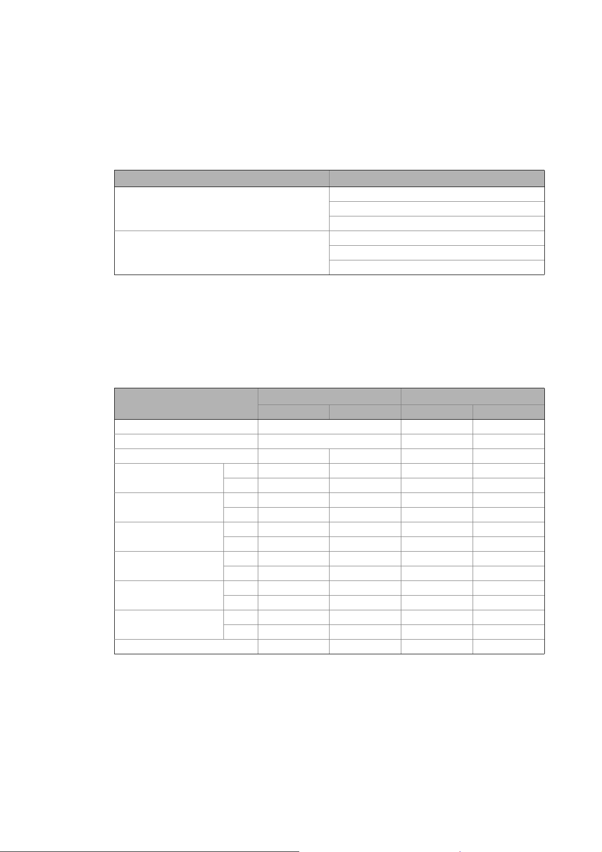
6.3 Device specifications of the field devices
When planning your CANopen network, consider the device specifications of the implemented field
devices.
Overview of the device specifications for operation with a Lenze Controller
Servo Drives 9400 Inverter Drives 8400 I/O-System 1000
(EPM-Sxxx)
CAN interface • on board
•CANopen module
Available PDOs 4 Transmit (Tx) +
4 Receive (Rx)
Can unused PDOs be
deactivated?
Can PDO COB-IDs be freely
selected?
Can PDO transfer characteristics
be adjusted?
Available SDO channels 1 ex works (fixed),
Can SDO COB-IDs be freely
selected?
yes yes yes
yes yes yes
yes yes yes
9 further can be activated
only for channel 2 ... 10 no no
on board on board
3 Transmit (Tx) +
3 Receive (Rx)
2 ex works (fixed) 1 ex works (fixed),
10 Transmit (Tx) +
10 Receive (Rx)
1 more can be activated
Lenze · Controller-based Automation · CANopen® Communication Manual · DMS 6.3 EN · 04/2014 · TD17 28
Page 29
6 Planning the CANopen network
6.3 Device specifications of the field devices
_ _ _ _ _ _ _ _ _ _ _ _ _ _ _ _ _ _ _ _ _ _ _ _ _ _ _ _ _ _ _ _ _ _ _ _ _ _ _ _ _ _ _ _ _ _ _ _ _ _ _ _ _ _ _ _ _ _ _ _ _ _ _ _
6.3.1 Special features of the 9400 Servo Drives
• The parameter data channel 1 is always active.
•The optional parameter data channels 2 ... 10 can be activated via the subcodes of the codes
Cxx372 and Cxx373.
SDO identifier Code
CANopen SDO server Rx identifier C00372: CAN on board
C13372: Module in slot 1
C14372: Module in slot 2
CANopen SDO server Tx identifier C00373: CAN on board
C13373: Module in slot 1
C14373: Module in slot 2
• If bit 31 is set (0x8nnnnnnn), the corresponding SDO server is deactivated.
• In order to change the COB-ID of a currently active parameter data channel, you have to first
deactivate it and then activate it with a changed COB-ID. Both processes must be rendered
effective by a "Reset Node" command via C00002.
Basic identifier - 9400 Servo Drives
The default setting of the basic identifier is as follows:
Object Direction Basic identifier
from the drive to the drive Dec hex
NMT 0 0x000
Sync 1) 128 0x080
Emergency 128 0x080
PDO1
(Process data channel 1)
PDO2
(Process data channel 2)
PDO3
(Process data channel 3)
PDO4
(Process data channel 4)
SDO1
(Parameter data channel 1)
SDO2 ... 10
(Parameter data channel 2 ... 10)
Node guarding, heartbeat 1792 0x700
TPDO1
RPDO1
TPDO2
RPDO2
TPDO3
RPDO3
TPDO4
RPDO4
TSDO1
RSDO1
TSDOx
RSDOx
384 0x180
512 0x200
640 0x280
768 0x300
896 0x380
1024 0x400
1152 0x480
1280 0x500
1408 0x580
1536 0x600
1472 0x5C0
1600 0x640
29
1) When creating the sync transmit/receive identifier manually, observe the use of the emergency telegram because
of the same COB-ID.
Lenze · Controller-based Automation · CANopen® Communication Manual · DMS 6.3 EN · 04/2014 · TD17
Page 30

6 Planning the CANopen network
6.3 Device specifications of the field devices
_ _ _ _ _ _ _ _ _ _ _ _ _ _ _ _ _ _ _ _ _ _ _ _ _ _ _ _ _ _ _ _ _ _ _ _ _ _ _ _ _ _ _ _ _ _ _ _ _ _ _ _ _ _ _ _ _ _ _ _ _ _ _ _
6.3.2 Special features of the 8400 Inverter Drives
Basic identifier - 8400 Inverter Drives
The default setting of the basic identifier is as follows:
Object Direction Basic identifier
from the drive to the drive Dec hex
NMT 0 0x000
Sync 1) 128 0x080
Emergency 128 0x080
PDO1
(Process data channel 1)
PDO2
(Process data channel 2)
PDO3
(Process data channel 3)
SDO1
(Parameter data channel 1)
SDO2
(Parameter data channel 2)
Heartbeat 1792 0x700
Boot-up 2) 1792 0x700
TPDO1
RPDO1
TPDO2
RPDO2
TPDO3
RPDO3
TSDO1
RSDO1
TSDO2
RSDO2
384 0x180
512 0x200
640 0x280
641 0x281
768 0x300
769 0x301
1408 0x580
1536 0x600
1472 0x5C0
1600 0x640
1) When creating the sync transmit/receive identifier manually, observe the use of the emergency telegram because
of the same COB-ID.
2) When the boot-up identifier is set manually, observe the use of heartbeat because of the same COB-ID.
Lenze · Controller-based Automation · CANopen® Communication Manual · DMS 6.3 EN · 04/2014 · TD17 30
Page 31

6 Planning the CANopen network
6.3 Device specifications of the field devices
_ _ _ _ _ _ _ _ _ _ _ _ _ _ _ _ _ _ _ _ _ _ _ _ _ _ _ _ _ _ _ _ _ _ _ _ _ _ _ _ _ _ _ _ _ _ _ _ _ _ _ _ _ _ _ _ _ _ _ _ _ _ _ _
6.3.3 Special features of the I/O system 1000 (EPM-Sxxx)
Basic identifier - I/O system 1000 (EPM-Sxxx)
The default setting of the basic identifier is as follows:
Object Direction Basic identifier
from the drive to the drive Dec hex
NMT 0 0x000
Sync 1) 128 0x080
Emergency 128 0x080
PDO1
(Process data channel 1)
PDO2
(Process data channel 2)
PDO3
(Process data channel 3)
PDO4
(Process data channel 4)
PDO5
(Process data channel 5)
PDO6
(Process data channel 6)
PDO7
(Process data channel 7)
PDO8
(Process data channel 8)
PDO9
(Process data channel 9)
PDO10
(Process data channel 10)
SDO1
(Parameter data channel 1)
Node guarding 1792 0x700
TPDO1
RPDO1
TPDO2
RPDO2
TPDO3
RPDO3
TPDO4
RPDO4
TPDO5
RPDO5
TPDO6
RPDO6
TPDO7
RPDO7
TPDO8
RPDO8
TPDO9
RPDO9
TPDO10
RPDO10
TSDO1
RSDO1
384 0x180
512 0x200
640 0x280
768 0x300
896 0x380
1024 0x400
1152 0x480
1280 0x500
1664 0x680
1920 0x780
448 0x1C0
576 0x240
704 0x2C0
832 0x340
960 0x3C0
1088 0x440
1216 0x4C0
1344 0x540
1728 0x6C0
1984 0x7C0
1408 0x580
1536 0x600
31
1) When creating the sync transmit/receive identifier manually, observe the use of the emergency telegram because
of the same COB-ID.
Lenze · Controller-based Automation · CANopen® Communication Manual · DMS 6.3 EN · 04/2014 · TD17
Page 32

6 Planning the CANopen network
6.4 Special case: Delayed switch-on of one or more slaves
_ _ _ _ _ _ _ _ _ _ _ _ _ _ _ _ _ _ _ _ _ _ _ _ _ _ _ _ _ _ _ _ _ _ _ _ _ _ _ _ _ _ _ _ _ _ _ _ _ _ _ _ _ _ _ _ _ _ _ _ _ _ _ _
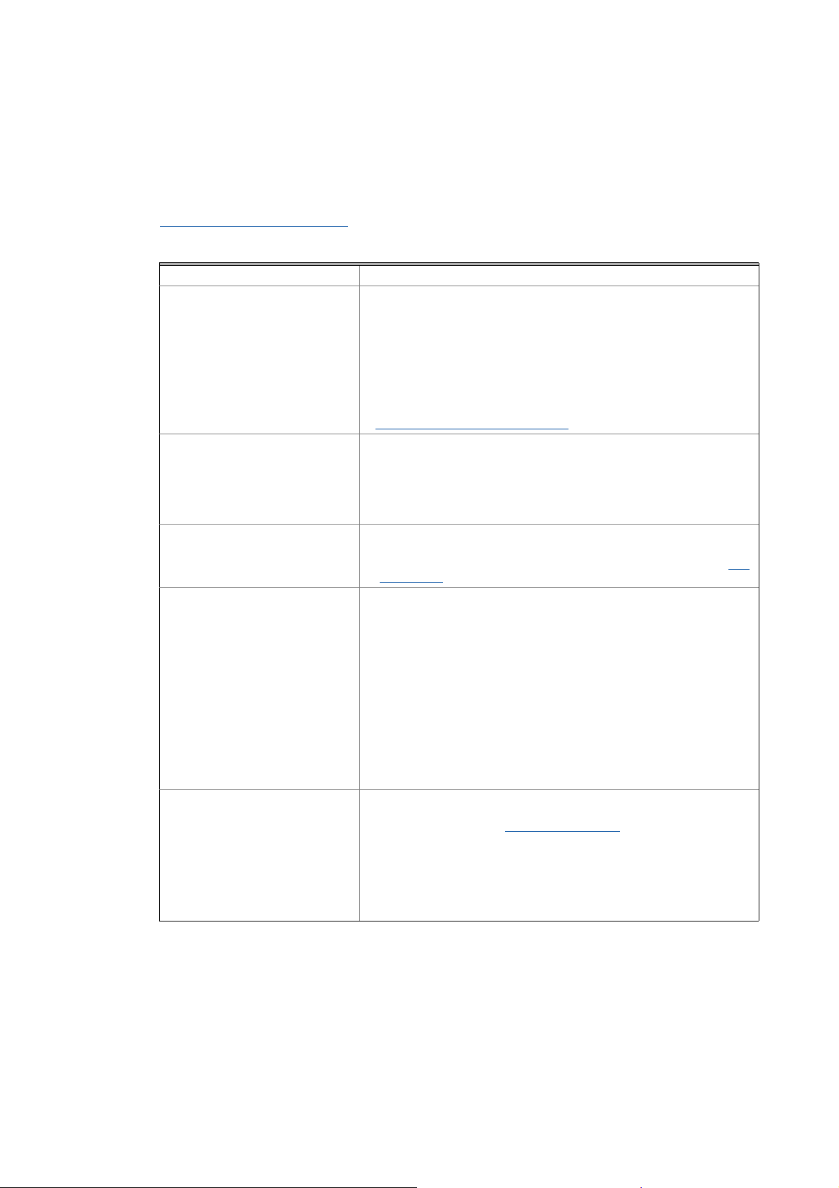
6.4 Special case: Delayed switch-on of one or more slaves
When the master is started, all slave devices must be switched on.
If this is not the case, a special procedure must be carried out for the following cases:
A. One or more
In this case, indicate each of these devices as "optional device" on the CANopen Remote Device
tab:
slaves are switched on later.
B. All
In this case, additionally
Manager tab:
slaves are switched on after the master starting process.
deactivate the "Polling of optional slaves" option on the CANopen
After switching on the slaves, the Reset Communication command must be executed with the
"NMT" function block which is provided in the CiA library.
Lenze · Controller-based Automation · CANopen® Communication Manual · DMS 6.3 EN · 04/2014 · TD17 32
Page 33

7Preparing the field devices
7.1 Installing field devices
_ _ _ _ _ _ _ _ _ _ _ _ _ _ _ _ _ _ _ _ _ _ _ _ _ _ _ _ _ _ _ _ _ _ _ _ _ _ _ _ _ _ _ _ _ _ _ _ _ _ _ _ _ _ _ _ _ _ _ _ _ _ _ _
7 Preparing the field devices
7.1 Installing field devices
Install the field devices according to the data given in the device-specific mounting instructions.
Make sure that ...
• the CANopen installation complies with your overview screen.
• all devices are supported by the control technology system on the Logic bus and Motion bus.
• in the case of devices with several CAN interfaces, the correct interfaces are connected to the
fieldbus.
• a terminating resistor is connected to the first and last node.
• the fieldbus is not unintentionally interrupted in switchable CAN connectors.
7.2 Setting node addresses and baud rate
• Set the specified node address and baud rate on the field devices via DIP switch (if available on
the device), or via parameter/code.
• Mark the devices the settings of which you have changed in your overview screen.
• Attach address labels to the devices.
Note!
• Each node address must be unambiguous and may only be assigned once in the
CANopen network.
• The baud rate must be set identically for all nodes.
• Observe the connection between bus cable length and baud rate.
Bus cable length
Configuration via the »WebConfig«/»EASY Starter« for the Lenze Controller/IPC
If the baud rate has been changed via the »WebConfig«, the Lenze Controller/IPC needs
to be restarted afterwards. Then an online connection to the CAN nodes can be
established with the »EASY Starter«.
( 22)
33
Information on the DIP switch settings can be found in the documentation for the field
devices.
Lenze · Controller-based Automation · CANopen® Communication Manual · DMS 6.3 EN · 04/2014 · TD17
Page 34

7Preparing the field devices
7.3 Connecting the Engineering PC to the Lenze Controller
_ _ _ _ _ _ _ _ _ _ _ _ _ _ _ _ _ _ _ _ _ _ _ _ _ _ _ _ _ _ _ _ _ _ _ _ _ _ _ _ _ _ _ _ _ _ _ _ _ _ _ _ _ _ _ _ _ _ _ _ _ _ _ _
7.3 Connecting the Engineering PC to the Lenze Controller
To commission the field devices, an online connection is required between the Engineering PC and
the field device. To establish an online connection between an Engineering PC and a field device (like
a controller), two ways are possible:
Direct coupling Lenze Controller as gateway
[7-1] Online connection between the Engineering PC and the field device
If the Lenze Controller has not been commissioned yet, directly connect the Engineering PC to the
CANopen bus to commission the field devices. To activate the Engineering PC, for example use the
USB system bus adapter (EMF2177IB). Then the download times are optimal and is it not necessary
to commission the controller first.
As soon as the Lenze Controller has been commissioned, no direct coupling should be used anymore
since it may disturb the real-time capability of the fieldbus. This especially applies to the CANopen
Motion bus. Here, the transmission of the sync telegram on time can be disturbed so that an
increased jitter on the fieldbus may be the result.
Moreover, each field device requires a second parameter data channel for independent bus access
by two masters (controllers). For some device types, the parameter data channel must be installed
separately, e.g. in the case of the Servo Drives 9400.
As an option, some controllers can operate two independent CAN interfaces. In this case, one
interface can be used for the connection with the Lenze Controller, the other for the direct
connection of the Engineering PC. Thus, two fieldbuses are created which are physically
independent. In this case, the real-time capability of the nodes on the Motion bus is not influenced
even with direct coupling. However, the wiring expense increases.
Lenze · Controller-based Automation · CANopen® Communication Manual · DMS 6.3 EN · 04/2014 · TD17 34
Page 35

7Preparing the field devices
7.3 Connecting the Engineering PC to the Lenze Controller
_ _ _ _ _ _ _ _ _ _ _ _ _ _ _ _ _ _ _ _ _ _ _ _ _ _ _ _ _ _ _ _ _ _ _ _ _ _ _ _ _ _ _ _ _ _ _ _ _ _ _ _ _ _ _ _ _ _ _ _ _ _ _ _
The communication speed with the field devices, when being commissioned, mainly depends on
whether the Lenze Controller is currently running or is stopped. In the latter case, the total
bandwidth of the fieldbus is provided to the gateway so that the speed advantage in the case of
direct coupling would only be marginal. Thus, the use of the Lenze Controller as gateway as part of
the control technology should be clearly preferred.
Information on the commissioning of Lenze field devices is provided in the chapter "Commissioning
the field devices" ( 39).
35
Lenze · Controller-based Automation · CANopen® Communication Manual · DMS 6.3 EN · 04/2014 · TD17
Page 36

8 Commissioning of the CANopen Logic bus
8.1 Sample projects (Application Samples)
_ _ _ _ _ _ _ _ _ _ _ _ _ _ _ _ _ _ _ _ _ _ _ _ _ _ _ _ _ _ _ _ _ _ _ _ _ _ _ _ _ _ _ _ _ _ _ _ _ _ _ _ _ _ _ _ _ _ _ _ _ _ _ _
8 Commissioning of the CANopen Logic bus
This chapter provides information for the commissioning of the CANopen Logic field devices in the
Lenze automation system.
Depending on the field devices used, the following Lenze Engineering tools
• »EASY Starter«
• »Engineer«
•»PLC Designer«
8.1 Sample projects (Application Samples)
There already exist sample projects (device application + PLC program) for commissioning of Lenze
Controllers.
The Lenze sample projects can be found in the MS Windows start menu under:
Start All programs Lenze AppSamples ...
( 19) are required:
The Lenze sample projects can also be opened in the »PLC Designer« via the menu command File
New project..., or using <Ctrl>+<N>.
Detailed information on the sample projects can be found in the following
documentation:
• SW_ApplicationSample_i700_(PLC Designer V3)_Vx-y_DE/EN.pdf
• SW_ApplicationSamples_(Controller-based)_Vx-y_DE/EN.pdf
Lenze · Controller-based Automation · CANopen® Communication Manual · DMS 6.3 EN · 04/2014 · TD17 36
Page 37

8 Commissioning of the CANopen Logic bus
8.2 Overview of the commissioning steps
_ _ _ _ _ _ _ _ _ _ _ _ _ _ _ _ _ _ _ _ _ _ _ _ _ _ _ _ _ _ _ _ _ _ _ _ _ _ _ _ _ _ _ _ _ _ _ _ _ _ _ _ _ _ _ _ _ _ _ _ _ _ _ _
8.2 Overview of the commissioning steps
Step Activity Lenze Engineering tool to be
1. Create a project folder
2. Commissioning the field devices
3. Creating a PLC program with a target system (Logic)
4. Configuring the communication parameters
5. Importing missing devices / device description files
6. Creating a control configuration (adding field devices)
7. Setting of CAN parameters and PDO mapping
8. Creating the program code for controlling the Logic field device
9. Preparing the restart
10. Compiling the PLC program code
11. Logging in on the Lenze Controller with the »PLC Designer«
With the log-in, the fieldbus configuration and the PLC program are
loaded into the Controller.
12. Starting the PLC program
( 38)
( 39) »Engineer« / »EASY Starter«
( 40) »PLC Designer«
( 42)
( 44)
( 45)
( 50)
( 57)
( 59)
( 64)
( 64)
( 64)
used
In the following sections, the individual commissioning steps are described.
Follow the instructions of these sections step by step in order to commission your system.
More detailed information about how to work with the Lenze Engineering tools can be
found in the corresponding manuals and online helps.
37
Lenze · Controller-based Automation · CANopen® Communication Manual · DMS 6.3 EN · 04/2014 · TD17
Page 38

8 Commissioning of the CANopen Logic bus
8.3 Create a project folder
_ _ _ _ _ _ _ _ _ _ _ _ _ _ _ _ _ _ _ _ _ _ _ _ _ _ _ _ _ _ _ _ _ _ _ _ _ _ _ _ _ _ _ _ _ _ _ _ _ _ _ _ _ _ _ _ _ _ _ _ _ _ _ _
8.3 Create a project folder
Create a project folder on the Engineering PC.
Use this project folder to store the data generated in the following different project configuration
steps:
• Project data created in the »Engineer« or »EASY Starter«
• The project file created in the »PLC Designer«
Tip!
Create a separate project folder for every CAN configuration for storing the project files.
Lenze · Controller-based Automation · CANopen® Communication Manual · DMS 6.3 EN · 04/2014 · TD17 38
Page 39

8 Commissioning of the CANopen Logic bus
8.4 Commissioning the field devices
_ _ _ _ _ _ _ _ _ _ _ _ _ _ _ _ _ _ _ _ _ _ _ _ _ _ _ _ _ _ _ _ _ _ _ _ _ _ _ _ _ _ _ _ _ _ _ _ _ _ _ _ _ _ _ _ _ _ _ _ _ _ _ _
8.4 Commissioning the field devices
Parameterise the Lenze field devices connected to the CANopen network by means of the
»Engineer« or »EASY Starter«.
CANopen is exclusively configured by means of the »PLC Designer«.
CANopen settings of the field devices which have possibly been carried out with the »Engineer«/
»EASY Starter« are overwritten.
Documentation of the Lenze field devices
Detailed information about the commissioning of the Lenze field devices is provided
here.
Tip!
We recommend to commission each field device individually and then integrate them into
the PLC program.
There already exist sample projects (device application + PLC program) for commissioning
of Lenze Controllers.
Sample projects (Application Samples)
( 36)
39
Lenze · Controller-based Automation · CANopen® Communication Manual · DMS 6.3 EN · 04/2014 · TD17
Page 40

8 Commissioning of the CANopen Logic bus
8.5 Creating a PLC program with a target system (Logic)
_ _ _ _ _ _ _ _ _ _ _ _ _ _ _ _ _ _ _ _ _ _ _ _ _ _ _ _ _ _ _ _ _ _ _ _ _ _ _ _ _ _ _ _ _ _ _ _ _ _ _ _ _ _ _ _ _ _ _ _ _ _ _ _
8.5 Creating a PLC program with a target system (Logic)
The »PLC Designer« serves to model the network topology in the control configuration.
Tip!
The »PLC Designer« can be used to configure CANopen nodes and nodes on other fieldbus
systems.
Mixed operation of CANopen and EtherCAT
( 92)
How to create a PLC program in the »PLC Designer«:
1. Use the menu command File New project to create a new »PLC Designer« project.
2. Select "Standard project" in the New Project dialog window.
A "Standard object" simplifies the structure of a project in the »PLC Designer«; for instance,
a device tree structure with a target system, PLC logic, etc. is provided.
• Go to the Name input field and enter a name for your »PLC Designer« project.
• Select the previously created project folder as storage location in the Location
selection field.
Create a project folder
3. Confirm the entries by clicking OK.
Lenze · Controller-based Automation · CANopen® Communication Manual · DMS 6.3 EN · 04/2014 · TD17 40
( 38)
Page 41

8 Commissioning of the CANopen Logic bus
8.5 Creating a PLC program with a target system (Logic)
_ _ _ _ _ _ _ _ _ _ _ _ _ _ _ _ _ _ _ _ _ _ _ _ _ _ _ _ _ _ _ _ _ _ _ _ _ _ _ _ _ _ _ _ _ _ _ _ _ _ _ _ _ _ _ _ _ _ _ _ _ _ _ _
4. Go to the Standard project dialog window and select the target system in the Device
selection field:
Lenze Logic Controller
For actuating controllers that execute simple movements, have no Motion functionality, or
are controlled via pure PLC functionalities.
Further optional project settings
Selection of the Lenze control technology release version
Selection of the compiler version
5. Confirm the selection by clicking OK.
Selection of the programming language:
• Sequential function chart (SFC)
• Instruction list (IL)
• Continuous Function Chart (CFC)
• Function block diagram (FBD)
• Ladder diagram (LD)
• Structured text (ST)
41
Lenze · Controller-based Automation · CANopen® Communication Manual · DMS 6.3 EN · 04/2014 · TD17
Page 42

8 Commissioning of the CANopen Logic bus
8.6 Configuring the communication parameters
_ _ _ _ _ _ _ _ _ _ _ _ _ _ _ _ _ _ _ _ _ _ _ _ _ _ _ _ _ _ _ _ _ _ _ _ _ _ _ _ _ _ _ _ _ _ _ _ _ _ _ _ _ _ _ _ _ _ _ _ _ _ _ _
8.6 Configuring the communication parameters
Set the communication parameters to establish an online connection to the Lenze Controller later
on.
How to configure the communication parameters
1. Go to the Communication settings tab of the target system (device) and click the Add
gateway button.
Then go to the Gateway dialog box and enter the IP address of the controller. (By
double-clicking the predefined value it can be overwritten.)
2. Confirm the entry by clicking OK.
Lenze · Controller-based Automation · CANopen® Communication Manual · DMS 6.3 EN · 04/2014 · TD17 42
Page 43

8 Commissioning of the CANopen Logic bus
8.6 Configuring the communication parameters
_ _ _ _ _ _ _ _ _ _ _ _ _ _ _ _ _ _ _ _ _ _ _ _ _ _ _ _ _ _ _ _ _ _ _ _ _ _ _ _ _ _ _ _ _ _ _ _ _ _ _ _ _ _ _ _ _ _ _ _ _ _ _ _
3. Click the Scan network button.
4. Select the suitable controller for the IP address entered under 2. and activate it by
means of the Set active path button (or by double-click).
5. Now you can execute the following action using the »PLC Designer«:
Logging in on the Lenze Controller with the »PLC Designer«
( 64)
43
Lenze · Controller-based Automation · CANopen® Communication Manual · DMS 6.3 EN · 04/2014 · TD17
Page 44

8 Commissioning of the CANopen Logic bus
8.7 Importing missing devices / device description files
_ _ _ _ _ _ _ _ _ _ _ _ _ _ _ _ _ _ _ _ _ _ _ _ _ _ _ _ _ _ _ _ _ _ _ _ _ _ _ _ _ _ _ _ _ _ _ _ _ _ _ _ _ _ _ _ _ _ _ _ _ _ _ _
8.7 Importing missing devices / device description files
The device description file contains the data of the fieldbus peripherals required for the master
control. This file is required to program the control system.
With the »PLC Designer«, device descriptions for the following Lenze device series are installed as
well:
• i700 servo inverter
• Servo Drives 9400
• Inverter Drives 8400
• I/O system 1000 (EPM-Sxxx)
• Fieldbus communication cards for controller 3200 C / p500
(EtherCAT, CANopen, PROFIBUS)
In order to furthermore integrate missing devices or devices of other manufacturers, the
corresponding device description files of the manufacturer are required.
In the »PLC Designer« you can import device description files of the *.XML, *.devdesc.XML, *.EDS,
*.DCF, and *.GSx type via the menu command Tools Device Repository....
Tip!
Current device description files for Lenze devices can be found in the "Download" area at:
www.lenze.com
Lenze · Controller-based Automation · CANopen® Communication Manual · DMS 6.3 EN · 04/2014 · TD17 44
Page 45

8 Commissioning of the CANopen Logic bus
8.8 Creating a control configuration (adding field devices)
_ _ _ _ _ _ _ _ _ _ _ _ _ _ _ _ _ _ _ _ _ _ _ _ _ _ _ _ _ _ _ _ _ _ _ _ _ _ _ _ _ _ _ _ _ _ _ _ _ _ _ _ _ _ _ _ _ _ _ _ _ _ _ _
8.8 Creating a control configuration (adding field devices)
Note!
The configuration of a Lenze Controller in a CANopen network must be created in the
»PLC Designer«, because the complete configuration is written to the connected slaves
when a controller is started. This process overwrites the previous slave settings.
How to create the control configuration in the »PLC Designer«:
1. Go to the context menu of the target system and use the command Add Device to add
the "CANbus" to the control configuration.
45
Lenze · Controller-based Automation · CANopen® Communication Manual · DMS 6.3 EN · 04/2014 · TD17
Page 46

8 Commissioning of the CANopen Logic bus
8.8 Creating a control configuration (adding field devices)
_ _ _ _ _ _ _ _ _ _ _ _ _ _ _ _ _ _ _ _ _ _ _ _ _ _ _ _ _ _ _ _ _ _ _ _ _ _ _ _ _ _ _ _ _ _ _ _ _ _ _ _ _ _ _ _ _ _ _ _ _ _ _ _
2. Use the CANbus tab to set the baud rate.
Note!
The baud rate set in the »PLC Designer« overwrites the baud rate set for the field devices
via »Engineer« or »EASY Starter«.
Always set the same baud rate for all nodes in a CANopen network.
3. Use the Add Device to add the "CANopen Manager MC-CAN2" to the control
configuration.
Lenze · Controller-based Automation · CANopen® Communication Manual · DMS 6.3 EN · 04/2014 · TD17 46
Page 47
8 Commissioning of the CANopen Logic bus
8.8 Creating a control configuration (adding field devices)
_ _ _ _ _ _ _ _ _ _ _ _ _ _ _ _ _ _ _ _ _ _ _ _ _ _ _ _ _ _ _ _ _ _ _ _ _ _ _ _ _ _ _ _ _ _ _ _ _ _ _ _ _ _ _ _ _ _ _ _ _ _ _ _
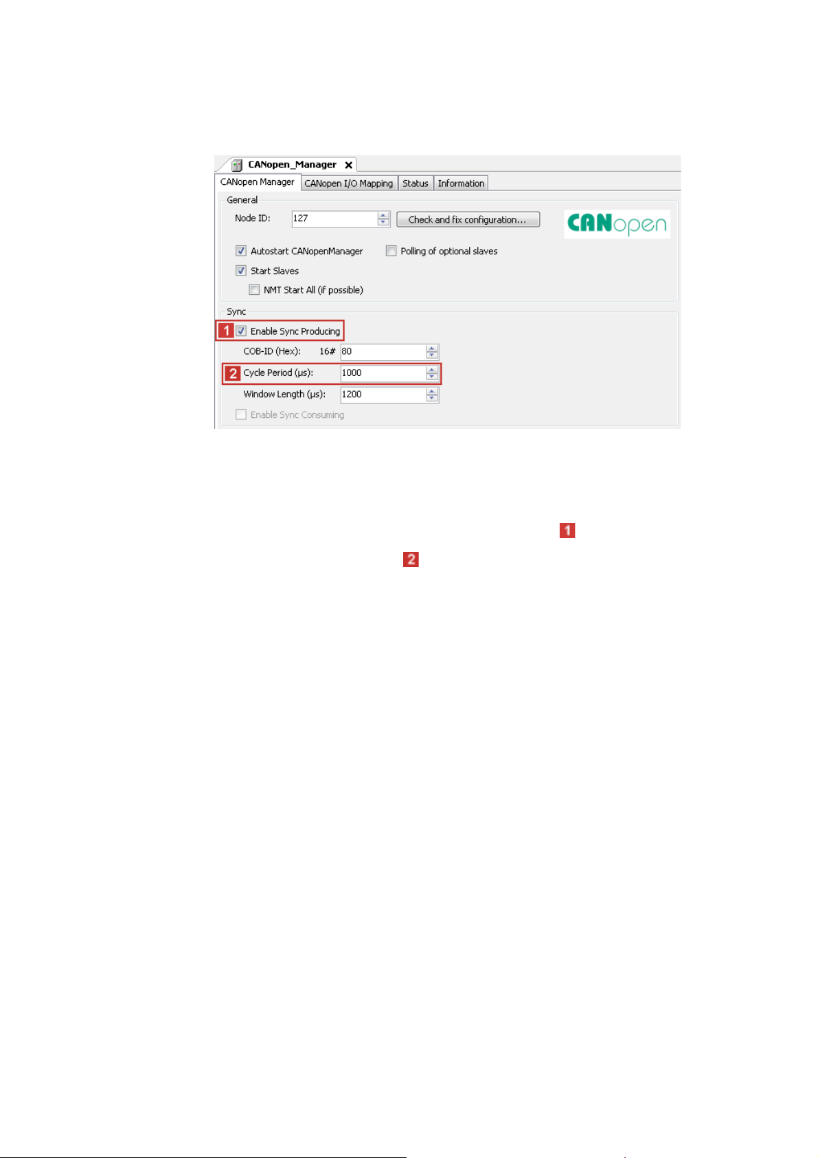
4. Use the CANopen_Manager tab to set the parameters for Sync generation.
Sync generation is required if ...
• at least one PDO with sync-controlled processing is used on the bus;
• the applications are to run in a clock-synchronised manner on several field devices;
• Motion devices are to be operated on the fieldbus.
If you want to use CAN synchronisation, tick the input field Enable Sync Producing.
Go to the input field and set the Cycle Period .
47
Lenze · Controller-based Automation · CANopen® Communication Manual · DMS 6.3 EN · 04/2014 · TD17
Page 48

8 Commissioning of the CANopen Logic bus
8.8 Creating a control configuration (adding field devices)
_ _ _ _ _ _ _ _ _ _ _ _ _ _ _ _ _ _ _ _ _ _ _ _ _ _ _ _ _ _ _ _ _ _ _ _ _ _ _ _ _ _ _ _ _ _ _ _ _ _ _ _ _ _ _ _ _ _ _ _ _ _ _ _
5. Use the command Add Device to add a Logic device (slave) to the CANopen_Manager
(master).
Select a field device from the selection list. You can only select devices the CANopen
device description files of which have been imported in the »PLC Designer«.
Importing missing devices / device description files
For EDS files created in the »Engineer«, the field device appears in the selection list with the
same name as during the export of the EDS file in the »Engineer«, extended by the name of
the interface and device type.
6. Repeat the Add Device command until all slaves connected to the fieldbus are included
in the control configuration.
( 44)
Lenze · Controller-based Automation · CANopen® Communication Manual · DMS 6.3 EN · 04/2014 · TD17 48
Page 49

8 Commissioning of the CANopen Logic bus
8.8 Creating a control configuration (adding field devices)
_ _ _ _ _ _ _ _ _ _ _ _ _ _ _ _ _ _ _ _ _ _ _ _ _ _ _ _ _ _ _ _ _ _ _ _ _ _ _ _ _ _ _ _ _ _ _ _ _ _ _ _ _ _ _ _ _ _ _ _ _ _ _ _
7. Give the inserted slaves suitable names (e.g. "Drive_vertical").
The names must …
• only contain the characters "A ... Z", "a ... z", "0 ... 9" or "_";
• not begin with a digit.
You can enter a name by clicking the element.
Example:
49
Lenze · Controller-based Automation · CANopen® Communication Manual · DMS 6.3 EN · 04/2014 · TD17
Page 50

8 Commissioning of the CANopen Logic bus
8.9 Setting of CAN parameters and PDO mapping
_ _ _ _ _ _ _ _ _ _ _ _ _ _ _ _ _ _ _ _ _ _ _ _ _ _ _ _ _ _ _ _ _ _ _ _ _ _ _ _ _ _ _ _ _ _ _ _ _ _ _ _ _ _ _ _ _ _ _ _ _ _ _ _
8.9 Setting of CAN parameters and PDO mapping
Set the CAN parameter and the PDO mapping for each Logic device connected to the bus.
How to set CAN parameters and CAN mapping:
1. Go to the CANopen Remote Device tab of the respective slave.
Use the input field Node ID to set the node address corresponding to the settings in the
field devices:
The following possible settings are only displayed if the Enable Expert Settings option
is ticked.
Make the settings required for your application.
Lenze · Controller-based Automation · CANopen® Communication Manual · DMS 6.3 EN · 04/2014 · TD17 50
Page 51
8 Commissioning of the CANopen Logic bus
8.9 Setting of CAN parameters and PDO mapping
_ _ _ _ _ _ _ _ _ _ _ _ _ _ _ _ _ _ _ _ _ _ _ _ _ _ _ _ _ _ _ _ _ _ _ _ _ _ _ _ _ _ _ _ _ _ _ _ _ _ _ _ _ _ _ _ _ _ _ _ _ _ _ _
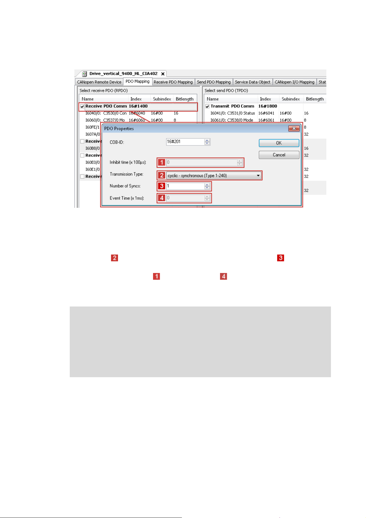
2. Go to the PDO Mapping tab.
The default setting for PDO mapping is a position mapping. This mapping can be changed
manually (by ticking). Due to the limited bandwidth of the CAN bus, this is only useful in
special cases. The default PDO properties, too, are useful default settings and should not be
changed.
If you double-click an individual PDO, its transmission properties are displayed.
•The Transmission Type "cyclic - synchronous (type 1-240)" and the setting, at
which sync the PDOs are to be sent, must not be changed.
• The settings for the Inhibit Time and the Event Time are not evaluated.
• Confirm the settings with the OK button.
On the CANopen I/O Mapping tab, PLC variables can be assigned to the process image.
Note!
Bus operation without CAN synchronisation
• The Lenze Controller always transmits asynchronous PDOs from an unsolicited task in
an event-controlled way. To achieve a time-controlled transmission of asynchronous
PDOs by the controller, you must assign the CAN master (controller) to a cyclic task.
• The Lenze Controller does not support any monitoring times for asynchronous
receive-PDOs. This is only possible with field devices.
51
Lenze · Controller-based Automation · CANopen® Communication Manual · DMS 6.3 EN · 04/2014 · TD17
Page 52

8 Commissioning of the CANopen Logic bus
8.9 Setting of CAN parameters and PDO mapping
_ _ _ _ _ _ _ _ _ _ _ _ _ _ _ _ _ _ _ _ _ _ _ _ _ _ _ _ _ _ _ _ _ _ _ _ _ _ _ _ _ _ _ _ _ _ _ _ _ _ _ _ _ _ _ _ _ _ _ _ _ _ _ _
3. The selection of a special bus cycle task on the CANopen I/O Mapping tab of the CANopen
manager is not essential.
In the standard setting, the task accessing devices of the CAN master with the shortest
cycle time is automatically used as the bus cycle task:
The "Cycle settings of the higher-level bus" serve to use the bus cycle task set via the PLC
settings tab of the Lenze Controller (device):
Lenze · Controller-based Automation · CANopen® Communication Manual · DMS 6.3 EN · 04/2014 · TD17 52
Page 53

8 Commissioning of the CANopen Logic bus
8.9 Setting of CAN parameters and PDO mapping
_ _ _ _ _ _ _ _ _ _ _ _ _ _ _ _ _ _ _ _ _ _ _ _ _ _ _ _ _ _ _ _ _ _ _ _ _ _ _ _ _ _ _ _ _ _ _ _ _ _ _ _ _ _ _ _ _ _ _ _ _ _ _ _
8.9.1 Cross communication between the slaves
With control via the CAN bus, cross communication between the slaves is possible. For this purpose,
you must configure the CAN communication and the PDO mapping in the »Engineer« and write it
to the controllers.
Since the mapping for the cross communication between the slaves is not available in the control
configuration, you must set the "No initialisation" option in the »PLC Designer« on the CANopen
Remote Device tab of the respective slaves.
Thus the CAN settings and mapping settings in the slave drives will not be overwritten by the Lenze
Controller when the PLC program starts.
Note!
In addition to the cross communication between the slaves, communication with the
master must also be configured in the »Engineer«.
If the "No initialisation" option is active, this part of the PDO mapping is also not
overwritten by the Lenze Controller.
53
Lenze · Controller-based Automation · CANopen® Communication Manual · DMS 6.3 EN · 04/2014 · TD17
Page 54

8 Commissioning of the CANopen Logic bus
8.9 Setting of CAN parameters and PDO mapping
_ _ _ _ _ _ _ _ _ _ _ _ _ _ _ _ _ _ _ _ _ _ _ _ _ _ _ _ _ _ _ _ _ _ _ _ _ _ _ _ _ _ _ _ _ _ _ _ _ _ _ _ _ _ _ _ _ _ _ _ _ _ _ _
8.9.2 Special features of the I/O system 1000 (EPM-Sxxx)
Note!
Before adding I/O modules beneath an EPM-S110 »PLC Designer«head station in the ,
the head station tab must be closed.
If the I/O 1000 modules are added when the head station tab is open, there will not be
shown any I/O image for the modules.
When all modules have been added, the EPM-S110 head station tab can be opened
again.
When using the EPM-S600 ... S604 counter modules at the EPM-S110 head station, the following
sequence must be observed when creating the configuration in the »PLC Designer«.
How to configure the EPM-S600 ... S604 counter modules:
1. Add EPM-S110 to the »PLC Designer« device configuration.
2. Add I/O discs and counter discs.
3. For EPM-S110,
•activate Enable Expert Settings;
• deactivate Autoconfig. PDO Mapping.
4. Execute the menu command Window Close All Editors.
5. Open EPM-S110 again with a double-click.
Lenze · Controller-based Automation · CANopen® Communication Manual · DMS 6.3 EN · 04/2014 · TD17 54
Page 55

8 Commissioning of the CANopen Logic bus
8.9 Setting of CAN parameters and PDO mapping
_ _ _ _ _ _ _ _ _ _ _ _ _ _ _ _ _ _ _ _ _ _ _ _ _ _ _ _ _ _ _ _ _ _ _ _ _ _ _ _ _ _ _ _ _ _ _ _ _ _ _ _ _ _ _ _ _ _ _ _ _ _ _ _
6. Add the PDO configuration for the counter discs.
The following example uses a receive PDO and a mapping element to describe the basic
configuration process.
Proceed accordingly for configuring the send PDOs ("Send PDO Mapping" tab).
A) Use the Add PDO button and add the receive PDO.
• Depending on the counter discs used, one or several PDOs must be added in send and
receive direction.
• Please refer to the module documentation to see which additional elements of the
process image of the counter modules are required for operation.
• The properties of the PDO can be defined via the "PDO properties" dialog box.
55
Lenze · Controller-based Automation · CANopen® Communication Manual · DMS 6.3 EN · 04/2014 · TD17
Page 56

8 Commissioning of the CANopen Logic bus
8.9 Setting of CAN parameters and PDO mapping
_ _ _ _ _ _ _ _ _ _ _ _ _ _ _ _ _ _ _ _ _ _ _ _ _ _ _ _ _ _ _ _ _ _ _ _ _ _ _ _ _ _ _ _ _ _ _ _ _ _ _ _ _ _ _ _ _ _ _ _ _ _ _ _
B) Manually create the mapping of the new PDOs.
• Select PDO and click Add Mapping.
• Select the corresponding settings in the dialog box that appears.
Note!
If Autoconfig. PDO Mapping (see step 3) is reactivated after adding the manual
configuration, the entire configuration that has been added manually will be deleted.
Lenze · Controller-based Automation · CANopen® Communication Manual · DMS 6.3 EN · 04/2014 · TD17 56
Page 57

8 Commissioning of the CANopen Logic bus
8.10 Creating the program code for controlling the Logic field device
_ _ _ _ _ _ _ _ _ _ _ _ _ _ _ _ _ _ _ _ _ _ _ _ _ _ _ _ _ _ _ _ _ _ _ _ _ _ _ _ _ _ _ _ _ _ _ _ _ _ _ _ _ _ _ _ _ _ _ _ _ _ _ _
8.10 Creating the program code for controlling the Logic field device
Note!
All program blocks which are operated with an SDO communication must be called up
in the same Logic task. Otherwise, jobs will get lost.
If the device descriptions for logic devices that are supplied with the »PLC Designer« are
used, the process data are copied to the subordinate logic drive node automatically. (For
further information see SW_Commissioning_Lenze_(Controller-based)_Vx-y_EN.pdf,
chapter "Overview of device descriptions".)
If the process data are to be continued to be linked manually, go to the LenzeLogicDrive
Configuration tab and activate this option:
Then continue to create the program code.
57
Lenze · Controller-based Automation · CANopen® Communication Manual · DMS 6.3 EN · 04/2014 · TD17
Page 58

8 Commissioning of the CANopen Logic bus
8.10 Creating the program code for controlling the Logic field device
_ _ _ _ _ _ _ _ _ _ _ _ _ _ _ _ _ _ _ _ _ _ _ _ _ _ _ _ _ _ _ _ _ _ _ _ _ _ _ _ _ _ _ _ _ _ _ _ _ _ _ _ _ _ _ _ _ _ _ _ _ _ _ _
How to create the program code:
1. Create the program code for controlling the field device.
The device must be used in the program code in order that the SDO initialisation takes
place.
If other field devices are added to the control configuration, this may change the object
addresses (%Qxx, %Ixx) of the existing variables. For this reason, do not use addresses
directly in the program code to access the input and output objects or to assign values to
them. Use the CANopen I/O Mapping tab for this purpose and assign own unique variable
names according to the IEC 61131 syntax (no blanks and leading digits in the variable
name):
Already existing variables (e.g. global variables from the function libraries) can be
integrated via the button .
The manual assignment of object addresses in the Address column is not supported. Hence,
only use the automatically assigned addresses of the process image. A manual assignment
causes malfunctions.
2. Completely compile the »PLC Designer« project and transfer it to the Lenze Controller.
Menu command: Build Build
Special features of the I/O system 1000 (EPM-Sxxx)
• When the program starts, the Lenze Controller initialises the I/O system. It changes to the
"Operational" status.
• When the Lenze Controller initialises the I/O system, the »Engineer« must not be online on the
same SDO channel.
Lenze · Controller-based Automation · CANopen® Communication Manual · DMS 6.3 EN · 04/2014 · TD17 58
Page 59

8 Commissioning of the CANopen Logic bus
8.11 Preparing the restart
_ _ _ _ _ _ _ _ _ _ _ _ _ _ _ _ _ _ _ _ _ _ _ _ _ _ _ _ _ _ _ _ _ _ _ _ _ _ _ _ _ _ _ _ _ _ _ _ _ _ _ _ _ _ _ _ _ _ _ _ _ _ _ _
8.11 Preparing the restart
In the control technology system you can use the Lenze Controller to transmit the complete
parameter setting via SDO initialisation to the field devices when the machine is switched on.
According to DS301, the Lenze Controller always initialises the CAN parameters of the field devices.
Additionally the controller can initialise further parameters. The values for this must be stored in
the Control configuration under the Service Data Objects tab.
Usually, the Lenze Controller only transmits the SDO objects for which you have stored another
value than the standard value. The controller does not
values in the field device. Thus, not all parameters changed there may be set correctly.
If you want a factory adjustment to be carried out in the field device before the SDO initialisation is
carried out, tick under the CANopen Remote Device tab ...
1. "Enable Expert Settings",
2. "Default Settings":
compare these values with the existing
Note!
During a factory adjustment, the parameter setting in the field device, which you have
carried out with the »Engineer«, gets lost. In this case, you have to transmit all parameter
values manually to the Service Data Objects tab. This only makes sense when
commissioning is completed and all parameters are optimised. If you change something
afterwards via the »Engineer«, you have to maintain it in the PLC program.
The Service Data Objects tab contains the codes which are written in the EDS file. The EDS file
contains all writable codes.
59
Lenze · Controller-based Automation · CANopen® Communication Manual · DMS 6.3 EN · 04/2014 · TD17
Page 60

8 Commissioning of the CANopen Logic bus
8.11 Preparing the restart
_ _ _ _ _ _ _ _ _ _ _ _ _ _ _ _ _ _ _ _ _ _ _ _ _ _ _ _ _ _ _ _ _ _ _ _ _ _ _ _ _ _ _ _ _ _ _ _ _ _ _ _ _ _ _ _ _ _ _ _ _ _ _ _
8.11.1 Special features of the 9400 Servo Drives HighLine
Servo Drives 9400 are not purely parameterisable devices. They require an application download,
where several files are transmitted to the memory module.
To put a Servo Drive 9400 into operation, you can:
• plug on the memory module.
• transmit the application using the »Engineer«. For this, you must keep the original »Engineer«
project.
• transmit the application using the »Loader«. For this, you must export and keep the required
files from the »Engineer« project:
8.11.2 Special features of the 8400 Inverter Drives
Inverter Drives 8400 are purely parameterisable devices.
To put an Inverter Drives 8400 into operation, you can transmit the application using the
»Engineer«. For this, you must keep the original »Engineer« project.
Lenze · Controller-based Automation · CANopen® Communication Manual · DMS 6.3 EN · 04/2014 · TD17 60
Page 61

8 Commissioning of the CANopen Logic bus
8.11 Preparing the restart
_ _ _ _ _ _ _ _ _ _ _ _ _ _ _ _ _ _ _ _ _ _ _ _ _ _ _ _ _ _ _ _ _ _ _ _ _ _ _ _ _ _ _ _ _ _ _ _ _ _ _ _ _ _ _ _ _ _ _ _ _ _ _ _
8.11.3 Special features of the I/O system 1000 (EPM-Sxxx)
There are different possibilities for restarting the I/O system:
• Automatically
• Automatically with factory adjustment
• Using the »Engineer«
For the corresponding settings, first tick the "Expert settings" on the CANopen Remote Device tab.
8.11.3.1 Automatic restart
Settings for automatic initialisation by the Lenze Controller:
1. Enter all desired parameter values under the All parameters tab.
2. Tick "Create all SDOs" under the CANopen Remote Device tab.
61
When the I/O system has been replaced
1. Set the node address and the baud rate at the code switch.
2. Start the Lenze Controller..
Lenze · Controller-based Automation · CANopen® Communication Manual · DMS 6.3 EN · 04/2014 · TD17
Page 62

8 Commissioning of the CANopen Logic bus
8.11 Preparing the restart
_ _ _ _ _ _ _ _ _ _ _ _ _ _ _ _ _ _ _ _ _ _ _ _ _ _ _ _ _ _ _ _ _ _ _ _ _ _ _ _ _ _ _ _ _ _ _ _ _ _ _ _ _ _ _ _ _ _ _ _ _ _ _ _
8.11.3.2 Automatic restart with factory adjustment
Settings for automatic initialisation with factory adjustment by the Lenze Controller:
1. Enter all desired parameter values under the All parameters tab.
2. Tick "Default settings" under the CANopen Remote Device tab.
When the I/O system has been replaced
1. Set the node address and the baud rate at the code switch.
2. Start the Lenze Controller.
Lenze · Controller-based Automation · CANopen® Communication Manual · DMS 6.3 EN · 04/2014 · TD17 62
Page 63

8 Commissioning of the CANopen Logic bus
8.11 Preparing the restart
_ _ _ _ _ _ _ _ _ _ _ _ _ _ _ _ _ _ _ _ _ _ _ _ _ _ _ _ _ _ _ _ _ _ _ _ _ _ _ _ _ _ _ _ _ _ _ _ _ _ _ _ _ _ _ _ _ _ _ _ _ _ _ _
8.11.3.3 Restart with the »Engineer«
Preconditions
• You have implemented the I/O system successfully into the PLC program.
• You have parameterised some CANopen indexes of the I/O system using the »Engineer«.
No transmission of the parameter setting to the Control configuration
You do not want to transmit the parameter setting to the Control configuration now, since you can
assume that after a possible device replacement the configuring software will be available.
• Operate the I/O system in CANopen mode.
•Do not
tick the "Default Settings" under the CANopen Remote Device tab in order that the Lenze
Controller does not execute a factory adjustment.
• Save the »Engineer« project near the machine.
When the I/O system has been replaced
1. Set the node address and the baud rate at the code switch.
2. Transmit the archived parameter setting to the I/O system.
3. Start the Lenze Controller.
63
Lenze · Controller-based Automation · CANopen® Communication Manual · DMS 6.3 EN · 04/2014 · TD17
Page 64

8 Commissioning of the CANopen Logic bus
8.12 Compiling the PLC program code
_ _ _ _ _ _ _ _ _ _ _ _ _ _ _ _ _ _ _ _ _ _ _ _ _ _ _ _ _ _ _ _ _ _ _ _ _ _ _ _ _ _ _ _ _ _ _ _ _ _ _ _ _ _ _ _ _ _ _ _ _ _ _ _
8.12 Compiling the PLC program code
In order to compile the PLC program code, select the menu command Build Build, or press
function key <F11>.
• If errors occur during translation, they can be located and corrected on the basis of the »PLC
Designer« error messages.
Then re-translate the program code.
• If no errors have occurred during the compilation process, save the »PLC Designer« project in the
project folder.
8.13 Logging in on the Lenze Controller with the »PLC Designer«
Use the menu command Online Login or <Alt>+<F8> to log in on the Lenze Controller.
• For this, the PLC program must be error-free.
• With the log-in, the fieldbus configuration and the PLC program are loaded to the controller.
Any possibly available configuration and PLC program are overwritten.
8.14 Starting the PLC program
Before the start, the PLC program must be loaded to the Lenze Controller using the menu command
Online Login.
Use the menu command Debug Start or function key <F5> to start the PLC program.
8.15 Start parameters of the Servo Drives 9400 HighLine CiA 402
When the Lenze Controller is started, the following "start parameters" are automatically loaded to
the Servo Drives 9400 HighLine CiA 402:
Index: Subindex
[hex]
0x5EEB:0x00 Signal source torque setpoint (C00275)
0x5B9E:0x00 Sync cycle time (C01121)
0x5B95:0x00 CAN SYNC application cycle (C01130)
0x60C0:0x01 Interpolation time unit
0x60C0:0x02 Interpolation time value
0x60C2:0x00 Selection of the interpolation submode
Name
Lenze · Controller-based Automation · CANopen® Communication Manual · DMS 6.3 EN · 04/2014 · TD17 64
Page 65

9 Commissioning of the CANopen Motion bus
_ _ _ _ _ _ _ _ _ _ _ _ _ _ _ _ _ _ _ _ _ _ _ _ _ _ _ _ _ _ _ _ _ _ _ _ _ _ _ _ _ _ _ _ _ _ _ _ _ _ _ _ _ _ _ _ _ _ _ _ _ _ _ _
9 Commissioning of the CANopen Motion bus
This chapter provides information on commissioning the CANopen Motion field devices in the Lenze
automation system.
The commissioning of a Motion device does not differ fundamentally from the commissioning of a
Logic device. Below a Motion device, an additional "SoftMotion" node is displayed in the device tree.
Via this node, further settings must be made.
Depending on the field devices used, the following Lenze Engineering tools
• »EASY Starter«
• »Engineer«
•»PLC Designer«
( 19) are required:
65 Lenze · Controller-based Automation · CANopen® Communication Manual · DMS 6.3 EN · 04/2014 · TD17
Page 66

9 Commissioning of the CANopen Motion bus
9.1 Sample projects (Application Samples)
_ _ _ _ _ _ _ _ _ _ _ _ _ _ _ _ _ _ _ _ _ _ _ _ _ _ _ _ _ _ _ _ _ _ _ _ _ _ _ _ _ _ _ _ _ _ _ _ _ _ _ _ _ _ _ _ _ _ _ _ _ _ _ _
9.1 Sample projects (Application Samples)
There already exist sample projects (device application + PLC program) for commissioning of Lenze
Controllers.
The Lenze sample projects can be found in the MS Windows start menu under:
Start All programs Lenze AppSamples ...
The Lenze sample projects can also be opened in the »PLC Designer« via the menu command File
New project..., or using <Ctrl>+<N>.
Detailed information on the sample projects can be found in the following
documentation:
• SW_ApplicationSample_i700_(PLC Designer V3)_Vx-y_DE/EN.pdf
• SW_ApplicationSamples_(Controller-based)_Vx-y_DE/EN.pdf
Lenze · Controller-based Automation · CANopen® Communication Manual · DMS 6.3 EN · 04/2014 · TD17 66
Page 67

9 Commissioning of the CANopen Motion bus
9.2 Overview of the commissioning steps
_ _ _ _ _ _ _ _ _ _ _ _ _ _ _ _ _ _ _ _ _ _ _ _ _ _ _ _ _ _ _ _ _ _ _ _ _ _ _ _ _ _ _ _ _ _ _ _ _ _ _ _ _ _ _ _ _ _ _ _ _ _ _ _
9.2 Overview of the commissioning steps
Step Activity Lenze Engineering tools to be
1. Create a project folder
2. Commissioning the field devices
3. Creating a PLC program with target system (Motion)
4. Configuring the communication parameters
5. Creating a Motion task
6. Creating a control configuration
7. Setting SoftMotion parameters
8. Setting of CAN parameters and PDO mapping
9. Creating the program code for controlling the Motion field device
10. Preparing the restart
11. Compiling the PLC program code
12. Logging in on the Lenze Controller with the »PLC Designer«
With the log-in, the fieldbus configuration and the PLC program are
loaded into the Controller.
13. Starting the PLC program
( 68)
( 69) »Engineer« / »EASY Starter«
( 70) »PLC Designer«
( 72)
( 74)
( 78)
( 84)
( 87)
( 90)
( 90)
( 91)
( 91)
( 91)
used
In the following sections, the individual commissioning steps are described.
Follow the instructions of these sections step by step in order to commission your system.
More detailed information about how to work with the Lenze Engineering tools can be
found in the corresponding manuals and online helps.
67
Lenze · Controller-based Automation · CANopen® Communication Manual · DMS 6.3 EN · 04/2014 · TD17
Page 68

9 Commissioning of the CANopen Motion bus
9.3 Create a project folder
_ _ _ _ _ _ _ _ _ _ _ _ _ _ _ _ _ _ _ _ _ _ _ _ _ _ _ _ _ _ _ _ _ _ _ _ _ _ _ _ _ _ _ _ _ _ _ _ _ _ _ _ _ _ _ _ _ _ _ _ _ _ _ _
9.3 Create a project folder
Create a project folder on the Engineering PC.
Use this project folder to store the data generated in the following different project configuration
steps:
• Project data created in the »Engineer« or »EASY Starter«
• The project file created in the »PLC Designer«
Tip!
Create a separate project folder for every CAN configuration for storing the project files.
Lenze · Controller-based Automation · CANopen® Communication Manual · DMS 6.3 EN · 04/2014 · TD17 68
Page 69

9 Commissioning of the CANopen Motion bus
9.4 Commissioning the field devices
_ _ _ _ _ _ _ _ _ _ _ _ _ _ _ _ _ _ _ _ _ _ _ _ _ _ _ _ _ _ _ _ _ _ _ _ _ _ _ _ _ _ _ _ _ _ _ _ _ _ _ _ _ _ _ _ _ _ _ _ _ _ _ _
9.4 Commissioning the field devices
Parameterise the Lenze field devices connected to the CANopen network by means of the
»Engineer« or »EASY Starter«.
Die CANopenis exclusively configured using the »PLC Designer«.
CANopen settings of the field devices which have possibly been carried out with the »Engineer«/
»EASY Starter« are overwritten.
Documentation of the Lenze field devices
Detailed information about the commissioning of the Lenze field devices is provided
here.
Tip!
We recommend to commission each field device individually and then integrate them into
the PLC program.
There already exist sample projects (device application + PLC program) for commissioning
of Lenze Controllers.
Sample projects (Application Samples)
For the Servo Drive 9400 Highline CiA 402 the following parameters must be set manually via the
»Engineer«:
• Homing mode (C02640, set in machine-dependent manner)
• Touch-probe interface (set in machine-dependent manner)
• Control of the holding brake (0x60FB/2 | Brake control)
Depending on the setting of this parameter, the holding brake is applied for a short time after
the conclusion of the home position path. In order to avoid this, set bit 2 in this parameter
("disable stop": does not apply the brake at standstill).
These parameters are not set via the Lenze Controller.
( 66)
69
Lenze · Controller-based Automation · CANopen® Communication Manual · DMS 6.3 EN · 04/2014 · TD17
Page 70

9 Commissioning of the CANopen Motion bus
9.5 Creating a PLC program with target system (Motion)
_ _ _ _ _ _ _ _ _ _ _ _ _ _ _ _ _ _ _ _ _ _ _ _ _ _ _ _ _ _ _ _ _ _ _ _ _ _ _ _ _ _ _ _ _ _ _ _ _ _ _ _ _ _ _ _ _ _ _ _ _ _ _ _
9.5 Creating a PLC program with target system (Motion)
The »PLC Designer« serves to model the network topology in the control configuration.
Tip!
The »PLC Designer« can be used to configure CANopen nodes and nodes on other fieldbus
systems.
Mixed operation of CANopen and EtherCAT
( 92)
How to create a PLC program in the »PLC Designer«:
1. Use the menu command File New project to create a new »PLC Designer« project.
2. Select "Standard project" in the New Project dialog window.
A "Standard object" simplifies the structure of a project in the »PLC Designer«; for instance,
a device tree structure with a target system, PLC logic, etc. is provided.
• Go to the Name input field and enter a name for your »PLC Designer« project.
• Select the previously created project folder as storage location in the Location
selection field.
Create a project folder
3. Confirm the entries by clicking OK.
Lenze · Controller-based Automation · CANopen® Communication Manual · DMS 6.3 EN · 04/2014 · TD17 70
( 68)
Page 71

9 Commissioning of the CANopen Motion bus
9.5 Creating a PLC program with target system (Motion)
_ _ _ _ _ _ _ _ _ _ _ _ _ _ _ _ _ _ _ _ _ _ _ _ _ _ _ _ _ _ _ _ _ _ _ _ _ _ _ _ _ _ _ _ _ _ _ _ _ _ _ _ _ _ _ _ _ _ _ _ _ _ _ _
4. Go to the Standard project dialog window and select the target system in the Device
selection field:
Lenze Motion Controller
For actuating controllers that, e.g. execute synchronised movements or have a Motion
functionality and are used for PLCopen libraries.
Further optional project settings
Selection of the Lenze control technology release version
Selection of the compiler version
5. Confirm the selection by clicking OK.
Selection of the programming language:
• Sequential function chart (SFC)
• Instruction list (IL)
• Continuous Function Chart (CFC)
• Function block diagram (FBD)
• Ladder diagram (LD)
• Structured text (ST)
71
Lenze · Controller-based Automation · CANopen® Communication Manual · DMS 6.3 EN · 04/2014 · TD17
Page 72

9 Commissioning of the CANopen Motion bus
9.6 Configuring the communication parameters
_ _ _ _ _ _ _ _ _ _ _ _ _ _ _ _ _ _ _ _ _ _ _ _ _ _ _ _ _ _ _ _ _ _ _ _ _ _ _ _ _ _ _ _ _ _ _ _ _ _ _ _ _ _ _ _ _ _ _ _ _ _ _ _
9.6 Configuring the communication parameters
Set the communication parameters to establish an online connection to the Lenze Controller later
on.
How to configure the communication parameters
1. Go to the Communication settings tab of the target system (device) and click the Add
gateway button.
Then go to the Gateway dialog box and enter the IP address of the controller. (By
double-clicking the predefined value it can be overwritten.)
2. Confirm the entry by clicking OK.
Lenze · Controller-based Automation · CANopen® Communication Manual · DMS 6.3 EN · 04/2014 · TD17 72
Page 73

9 Commissioning of the CANopen Motion bus
9.6 Configuring the communication parameters
_ _ _ _ _ _ _ _ _ _ _ _ _ _ _ _ _ _ _ _ _ _ _ _ _ _ _ _ _ _ _ _ _ _ _ _ _ _ _ _ _ _ _ _ _ _ _ _ _ _ _ _ _ _ _ _ _ _ _ _ _ _ _ _
3. Click the Scan network button.
4. Select the suitable controller for the IP address entered under 2. and activate it by
means of the Set active path button (or by double-click).
5. Now you can execute the following action using the »PLC Designer«:
Logging in on the Lenze Controller with the »PLC Designer«
( 91)
73
Lenze · Controller-based Automation · CANopen® Communication Manual · DMS 6.3 EN · 04/2014 · TD17
Page 74

9 Commissioning of the CANopen Motion bus
9.7 Creating a Motion task
_ _ _ _ _ _ _ _ _ _ _ _ _ _ _ _ _ _ _ _ _ _ _ _ _ _ _ _ _ _ _ _ _ _ _ _ _ _ _ _ _ _ _ _ _ _ _ _ _ _ _ _ _ _ _ _ _ _ _ _ _ _ _ _
9.7 Creating a Motion task
How to create a Motion task:
1. Go Task configuration in the configuration tree.
2. Create a new task with the Add Object command.
Assign a sensible task name (e.g. "MotionTask").
3. Enter a reasonable cycle time in milliseconds in the Interval input field.
The cycle time to be entered depends on the number of Motion axes and the runtime of the
PLC application. In case of a small PLC application, the minimum cycle time (T
determined by the number of Motion axes due to the transfer rate of the CANopen bus.
[ms] = number of Motion axes / 3
T
cycl
cycl
) is
Lenze · Controller-based Automation · CANopen® Communication Manual · DMS 6.3 EN · 04/2014 · TD17 74
Page 75

9 Commissioning of the CANopen Motion bus
9.7 Creating a Motion task
_ _ _ _ _ _ _ _ _ _ _ _ _ _ _ _ _ _ _ _ _ _ _ _ _ _ _ _ _ _ _ _ _ _ _ _ _ _ _ _ _ _ _ _ _ _ _ _ _ _ _ _ _ _ _ _ _ _ _ _ _ _ _ _
4. Go to Application in the configuration tree.
5. Use the Add Object command to create a new program block (POU) in the application.
Assign a reasonable POU name (e.g. "Motion_PRG").
.
75
Lenze · Controller-based Automation · CANopen® Communication Manual · DMS 6.3 EN · 04/2014 · TD17
Page 76

9 Commissioning of the CANopen Motion bus
9.7 Creating a Motion task
_ _ _ _ _ _ _ _ _ _ _ _ _ _ _ _ _ _ _ _ _ _ _ _ _ _ _ _ _ _ _ _ _ _ _ _ _ _ _ _ _ _ _ _ _ _ _ _ _ _ _ _ _ _ _ _ _ _ _ _ _ _ _ _
6. Add this program call to the task using the Add POU command.
Lenze · Controller-based Automation · CANopen® Communication Manual · DMS 6.3 EN · 04/2014 · TD17 76
Page 77

9 Commissioning of the CANopen Motion bus
9.7 Creating a Motion task
_ _ _ _ _ _ _ _ _ _ _ _ _ _ _ _ _ _ _ _ _ _ _ _ _ _ _ _ _ _ _ _ _ _ _ _ _ _ _ _ _ _ _ _ _ _ _ _ _ _ _ _ _ _ _ _ _ _ _ _ _ _ _ _
The following task configuration is caused:
77
Lenze · Controller-based Automation · CANopen® Communication Manual · DMS 6.3 EN · 04/2014 · TD17
Page 78

9 Commissioning of the CANopen Motion bus
9.8 Creating a control configuration
_ _ _ _ _ _ _ _ _ _ _ _ _ _ _ _ _ _ _ _ _ _ _ _ _ _ _ _ _ _ _ _ _ _ _ _ _ _ _ _ _ _ _ _ _ _ _ _ _ _ _ _ _ _ _ _ _ _ _ _ _ _ _ _
9.8 Creating a control configuration
Note!
The configuration of a Lenze Controller in a CANopen network must be created in the
»PLC Designer«, because the complete configuration is written to the connected slaves
when a controller is started. This process overwrites the previous slave settings.
How to create the control configuration in the »PLC Designer«:
1. Go to the context menu of the target system and use the command Add Device to add
the "CANbus" to the control configuration.
Lenze · Controller-based Automation · CANopen® Communication Manual · DMS 6.3 EN · 04/2014 · TD17 78
Page 79

9 Commissioning of the CANopen Motion bus
9.8 Creating a control configuration
_ _ _ _ _ _ _ _ _ _ _ _ _ _ _ _ _ _ _ _ _ _ _ _ _ _ _ _ _ _ _ _ _ _ _ _ _ _ _ _ _ _ _ _ _ _ _ _ _ _ _ _ _ _ _ _ _ _ _ _ _ _ _ _
2. Use the CANbus tab to set the baud rate.
Note!
The baud rate set in the »PLC Designer« overwrites the baud rate set for the field devices
via »WebConfig« or »Engineer«.
Always set the same baud rate for all nodes in a CANopen network.
3. Use the command Add Device to add the "CANopen Manager" to the control
configuration.
79
Lenze · Controller-based Automation · CANopen® Communication Manual · DMS 6.3 EN · 04/2014 · TD17
Page 80

9 Commissioning of the CANopen Motion bus
9.8 Creating a control configuration
_ _ _ _ _ _ _ _ _ _ _ _ _ _ _ _ _ _ _ _ _ _ _ _ _ _ _ _ _ _ _ _ _ _ _ _ _ _ _ _ _ _ _ _ _ _ _ _ _ _ _ _ _ _ _ _ _ _ _ _ _ _ _ _
4. Use the CANopen Manager tab to set the parameters for Sync generation.
Note!
To prevent the sync telegram from jittering, all Motion phases must be assigned to the
same task.
Sync generation is required if ...
• at least one PDO with sync-controlled processing is used on the bus;
• the applications are to run in a clock-synchronised manner on several field devices;
• Motion devices are to be operated on the bus.
If you want to use CAN synchronisation, tick the input field Enable Sync Producing.
Go to the input field and set the Cycle Period.
Lenze · Controller-based Automation · CANopen® Communication Manual · DMS 6.3 EN · 04/2014 · TD17 80
Page 81

9 Commissioning of the CANopen Motion bus
9.8 Creating a control configuration
_ _ _ _ _ _ _ _ _ _ _ _ _ _ _ _ _ _ _ _ _ _ _ _ _ _ _ _ _ _ _ _ _ _ _ _ _ _ _ _ _ _ _ _ _ _ _ _ _ _ _ _ _ _ _ _ _ _ _ _ _ _ _ _
5. Use the command Add Device to add a Motion device (slave) to the
CANopen_Manager (master).
Select a field device from the selection list.
For EDS files created in the »Engineer«, the field device appears in the selection list with the
same name as during the export of the EDS file in the »Engineer«, extended by the name of
the interface and device type.
6. Repeat the command Add Device until all slaves connected to the bus are integrated
into the control configuration.
7. Give the inserted slaves suitable names (e.g. "Drive_vertical").
The names must …
• only contain the characters "A ... Z", "a ... z", "0 ... 9" or "_";
• not begin with a digit.
You can enter a name by clicking the element.
Example:
81
Lenze · Controller-based Automation · CANopen® Communication Manual · DMS 6.3 EN · 04/2014 · TD17
Page 82

9 Commissioning of the CANopen Motion bus
9.9 Parallel operation of two synchronised CAN buses
_ _ _ _ _ _ _ _ _ _ _ _ _ _ _ _ _ _ _ _ _ _ _ _ _ _ _ _ _ _ _ _ _ _ _ _ _ _ _ _ _ _ _ _ _ _ _ _ _ _ _ _ _ _ _ _ _ _ _ _ _ _ _ _
9.9 Parallel operation of two synchronised CAN buses
The MC-CAN2 communication card is provided with two CAN interfaces. Thus, basically two CAN
buses can be operated independently of each other. The two buses can also be operated in a synccontrolled manner.
In the basic setting, which is sufficient for most application cases, there is an interval of the sync
telegrams of approx. 50 μs on the two buses.
If special cases require a different setting, the following optimisation can be carried out via the
»WebConfig« (see software manual for the Lenze Controller):
• Set the parameter "Sync master interface index" = 1 for "CAN interface 2".
• This reduces the interval of the sync telegrams on the two buses to approx. 20 μs.
Lenze · Controller-based Automation · CANopen® Communication Manual · DMS 6.3 EN · 04/2014 · TD17 82
Page 83

9 Commissioning of the CANopen Motion bus
9.9 Parallel operation of two synchronised CAN buses
_ _ _ _ _ _ _ _ _ _ _ _ _ _ _ _ _ _ _ _ _ _ _ _ _ _ _ _ _ _ _ _ _ _ _ _ _ _ _ _ _ _ _ _ _ _ _ _ _ _ _ _ _ _ _ _ _ _ _ _ _ _ _ _
In the device tree of the »PLC Designer« project, the CAN bus which works via CAN interface 1
(CAN1) must be first:
83
Lenze · Controller-based Automation · CANopen® Communication Manual · DMS 6.3 EN · 04/2014 · TD17
Page 84

9 Commissioning of the CANopen Motion bus
9.10 Setting SoftMotion parameters
_ _ _ _ _ _ _ _ _ _ _ _ _ _ _ _ _ _ _ _ _ _ _ _ _ _ _ _ _ _ _ _ _ _ _ _ _ _ _ _ _ _ _ _ _ _ _ _ _ _ _ _ _ _ _ _ _ _ _ _ _ _ _ _
9.10 Setting SoftMotion parameters
Note!
In the »PLC Designer«, the SoftMotion tabs are only available for field devices using a
Motion application (e.g. Servo Drive 9400 Highline CiA 402).
The SoftMotion parameters are to be set in relation to the application.
For the Servo Drive 9400 Highline CiA 402 the following parameters must be set manually via the
»Engineer«:
• Homing mode (C02640, set in application-dependent manner)
• Touch probe interface (set in application-dependent manner)
• Control of the holding brake (0x60FB/2 | Brake control)
Depending on the setting of this parameter, the holding brake is applied for a short time after
the conclusion of the home position path. In order to avoid this, set bit 2 in this parameter
("disable stop": does not apply the brake at standstill).
These parameters are not set via the Lenze Controller.
Example of a minimum configuration with a Motion device (Servo Drive 9400 HighLine CiA 402)
Lenze · Controller-based Automation · CANopen® Communication Manual · DMS 6.3 EN · 04/2014 · TD17 84
Page 85
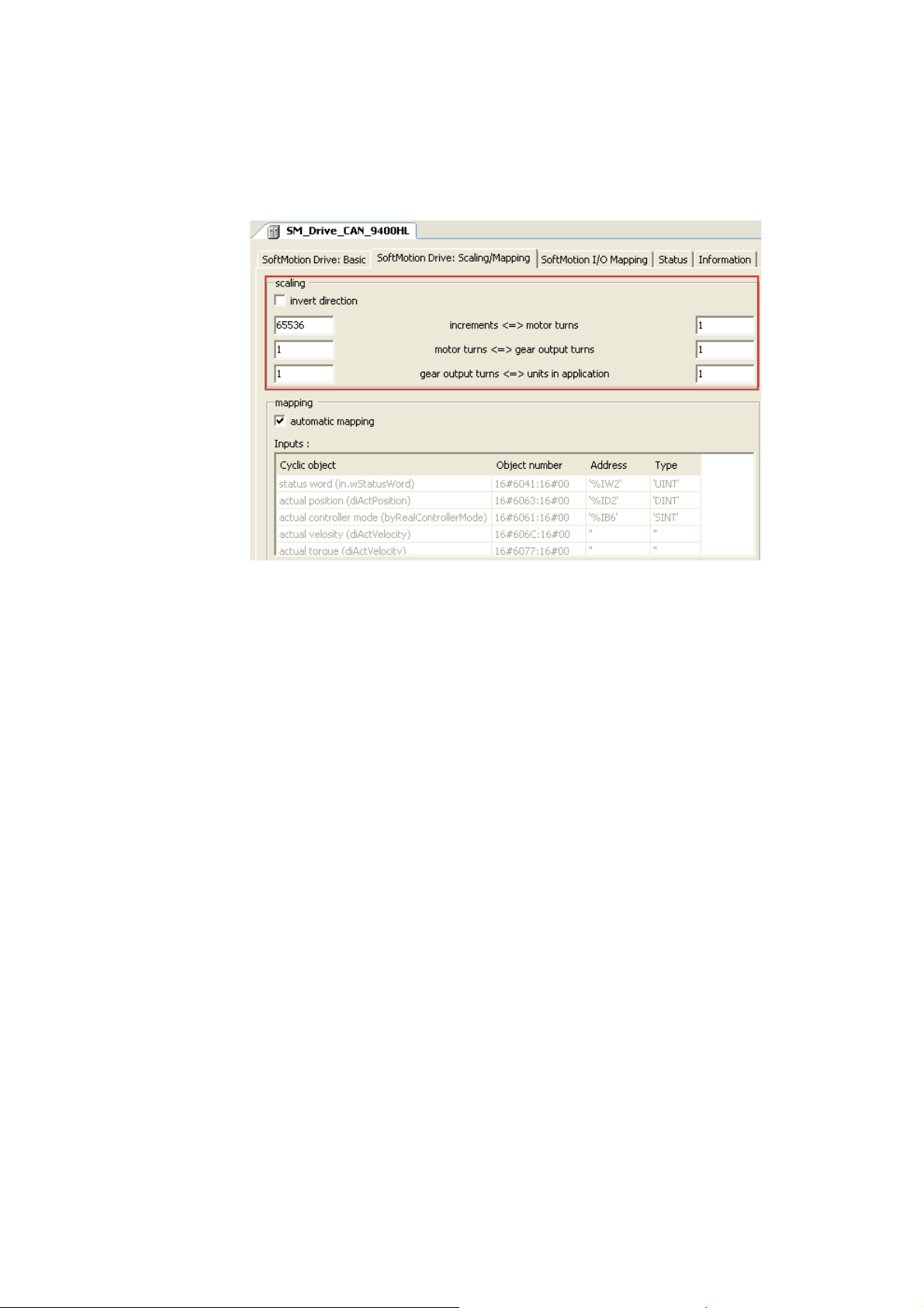
9 Commissioning of the CANopen Motion bus
9.10 Setting SoftMotion parameters
_ _ _ _ _ _ _ _ _ _ _ _ _ _ _ _ _ _ _ _ _ _ _ _ _ _ _ _ _ _ _ _ _ _ _ _ _ _ _ _ _ _ _ _ _ _ _ _ _ _ _ _ _ _ _ _ _ _ _ _ _ _ _ _
How to set the SoftMotion parameters
1. Open the tab SoftMotion drive: Scaling/Mapping and adapt the conversion factors in the
"Scaling" area.
85
Lenze · Controller-based Automation · CANopen® Communication Manual · DMS 6.3 EN · 04/2014 · TD17
Page 86

9 Commissioning of the CANopen Motion bus
9.10 Setting SoftMotion parameters
_ _ _ _ _ _ _ _ _ _ _ _ _ _ _ _ _ _ _ _ _ _ _ _ _ _ _ _ _ _ _ _ _ _ _ _ _ _ _ _ _ _ _ _ _ _ _ _ _ _ _ _ _ _ _ _ _ _ _ _ _ _ _ _
2. Open the tab SoftMotion drive: basic parameters and set the axis types and limitations.
• Do not use the "virtual mode" setting.
• Virtual axes are in the "SoftMotion General Drive Pool".
Configuration of a Motion device Rotary axis
(type: Modulo, 360°/revolution, ratio 1:1):
For configuring a linear axis Motion device (type: Finite), you can activate and determine
the software limit switches:
3. Repeat steps 1 and 2 for all Motion devices participating on the fieldbus.
Online help of »PLC Designer«
Here, you can find detailed descriptions of the SoftMotion tabs.
Lenze · Controller-based Automation · CANopen® Communication Manual · DMS 6.3 EN · 04/2014 · TD17 86
Page 87

9 Commissioning of the CANopen Motion bus
9.11 Setting of CAN parameters and PDO mapping
_ _ _ _ _ _ _ _ _ _ _ _ _ _ _ _ _ _ _ _ _ _ _ _ _ _ _ _ _ _ _ _ _ _ _ _ _ _ _ _ _ _ _ _ _ _ _ _ _ _ _ _ _ _ _ _ _ _ _ _ _ _ _ _
9.11 Setting of CAN parameters and PDO mapping
Set the CAN parameter and the PDO mapping for each Motion device connected to the bus.
How to set CAN parameters and CAN mapping:
1. Go to the CANopen Remote Device tab of the respective slave.
Use the input field Node ID to set the node address corresponding to the settings in the
field devices:
The following possible settings are only displayed if the Enable Expert Settings option
is ticked.
Make the settings required for your application.
87
Lenze · Controller-based Automation · CANopen® Communication Manual · DMS 6.3 EN · 04/2014 · TD17
Page 88

9 Commissioning of the CANopen Motion bus
9.11 Setting of CAN parameters and PDO mapping
_ _ _ _ _ _ _ _ _ _ _ _ _ _ _ _ _ _ _ _ _ _ _ _ _ _ _ _ _ _ _ _ _ _ _ _ _ _ _ _ _ _ _ _ _ _ _ _ _ _ _ _ _ _ _ _ _ _ _ _ _ _ _ _
2. Go to the PDO Mapping tab.
The default setting for PDO mapping is a position mapping. This mapping can be changed
manually (by ticking). Due to the limited bandwidth of the CAN bus, this is only useful in
special cases. The default PDO properties, too, are useful default settings and should not be
changed.
If you double-click an individual PDO, its transmission properties are displayed.
•The Transmission Type "cyclic - synchronous (type 1-240)" and the setting, at
which sync the PDOs are to be sent, must not be changed.
• The settings for the Inhibit Time and the Event Time are not evaluated.
• Confirm the settings with the OK button.
On the CANopen I/O Mapping tab, PLC variables can be assigned to the process image.
Note!
Bus operation without CAN synchronisation
• The Lenze Controller always transmits asynchronous PDOs from an unsolicited task in
an event-controlled way. To achieve a time-controlled transmission of asynchronous
PDOs by the controller, you must assign the CAN master to a cyclic task.
• The Lenze Controller does not support any monitoring times for asynchronous
receive-PDOs. This is only possible with field devices.
Lenze · Controller-based Automation · CANopen® Communication Manual · DMS 6.3 EN · 04/2014 · TD17 88
Page 89

9 Commissioning of the CANopen Motion bus
9.11 Setting of CAN parameters and PDO mapping
_ _ _ _ _ _ _ _ _ _ _ _ _ _ _ _ _ _ _ _ _ _ _ _ _ _ _ _ _ _ _ _ _ _ _ _ _ _ _ _ _ _ _ _ _ _ _ _ _ _ _ _ _ _ _ _ _ _ _ _ _ _ _ _
3. The selection of a special bus cycle task on the CANopen I/O Mapping tab of the CANopen
manager is not essential.
In the standard setting, the task accessing devices of the CAN master with the shortest
cycle time is automatically used as the bus cycle task:
The "Cycle settings of the higher-level bus" serve to use the bus cycle task set via the PLC
settings tab of the Lenze Controller (device):
89
Lenze · Controller-based Automation · CANopen® Communication Manual · DMS 6.3 EN · 04/2014 · TD17
Page 90

9 Commissioning of the CANopen Motion bus
9.12 Creating the program code for controlling the Motion field device
_ _ _ _ _ _ _ _ _ _ _ _ _ _ _ _ _ _ _ _ _ _ _ _ _ _ _ _ _ _ _ _ _ _ _ _ _ _ _ _ _ _ _ _ _ _ _ _ _ _ _ _ _ _ _ _ _ _ _ _ _ _ _ _
9.12 Creating the program code for controlling the Motion field device
This depends on the automation task, the use of PLCopen blocks or the CNC programming.
Note!
All SoftMotion function blocks, SoftMotion functions, and the read/write block
parameters that access the SoftMotion devices (e.g. MC_WriteParameter or
MC_WriteBoolParameter) must only be called from the Motion task.
If they are called from another task, their execution may be incorrect.
See also chapter "Creating the program code for controlling the Logic field device
9.13 Preparing the restart
Saving the parameter set of the drive via the »Engineer«.
See also Preparing the restart
" ( 57).
( 59).
Lenze · Controller-based Automation · CANopen® Communication Manual · DMS 6.3 EN · 04/2014 · TD17 90
Page 91

9 Commissioning of the CANopen Motion bus
9.14 Compiling the PLC program code
_ _ _ _ _ _ _ _ _ _ _ _ _ _ _ _ _ _ _ _ _ _ _ _ _ _ _ _ _ _ _ _ _ _ _ _ _ _ _ _ _ _ _ _ _ _ _ _ _ _ _ _ _ _ _ _ _ _ _ _ _ _ _ _
9.14 Compiling the PLC program code
In order to compile the PLC program code, select the menu command Build Build, or press
function key <F11>.
• If errors occur during translation, they can be located and corrected on the basis of the »PLC
Designer« error messages.
Then re-translate the program code.
• If no errors have occurred during the compilation process, save the »PLC Designer« project in the
project folder.
9.15 Logging in on the Lenze Controller with the »PLC Designer«
Use the menu command Online Login or <Alt>+<F8> to log in on the Lenze Controller.
• For this, the PLC program must be error-free.
• With the log-in, the fieldbus configuration and the PLC program are loaded to the controller.
Any possibly available configuration and PLC program are overwritten.
9.16 Starting the PLC program
Before the start, the PLC program must be loaded to the Lenze Controller using the menu command
Online Login.
Use the menu command Debug Start or function key <F5> to start the PLC program.
9.17 Start parameters of the Servo Drives 9400 HighLine CiA 402
When the Lenze Controller is started, the following "start parameters" are automatically loaded to
the Servo Drives 9400 HighLine CiA 402:
Index:Subindex
[hex]
0x5EEB:0x00 Signal source torque setpoint (C00275)
0x5B9E:0x00 Sync cycle time (C01121)
0x5B95:0x00 CAN SYNC application cycle (C01130)
0x60C0:0x01 Interpolation time unit
0x60C0:0x02 Interpolation time value
0x60C2:0x00 Selection of the interpolation submode
Name
91
Lenze · Controller-based Automation · CANopen® Communication Manual · DMS 6.3 EN · 04/2014 · TD17
Page 92

10 Mixed operation of CANopen and EtherCAT
_ _ _ _ _ _ _ _ _ _ _ _ _ _ _ _ _ _ _ _ _ _ _ _ _ _ _ _ _ _ _ _ _ _ _ _ _ _ _ _ _ _ _ _ _ _ _ _ _ _ _ _ _ _ _ _ _ _ _ _ _ _ _ _
10 Mixed operation of CANopen and EtherCAT
[10-1] Example: Mixed operation of EtherCAT with CANopen connected to a 3231 C controller with Servo-Inverter i700 and Servo
Drives 9400
Within the Lenze Controller-based Automation, CANopen can be used in parallel to the EtherCAT
bus system. This is useful if not all field devices are available for the same bus system or if, in parallel
to the CANopen bus as Logic bus, a Motion bus (EtherCAT) is required.
Note!
• Due to the requirements regarding the real time behaviour of the fieldbus system and
due to its limited transfer capacity, it is useful to operate Logic and Motion devices on
separate field bus lines if CANopen is used – on a logic bus and a motion bus.
• In mixed operation, ensure that the CAN Motion task has the highest priority. The task
assigned to the EtherCAT bus should have the second-highest priority. The tasks
assigned to the Logic bus systems should be configured with a lower priority.
Controller-based Automation EtherCAT communication manual
Here you can find information on the commissioning of EtherCAT components.
Lenze · Controller-based Automation · CANopen® Communication Manual · DMS 6.3 EN · 04/2014 · TD17 92
Page 93

11 SM3_Drive_Lenze.lib function library
_ _ _ _ _ _ _ _ _ _ _ _ _ _ _ _ _ _ _ _ _ _ _ _ _ _ _ _ _ _ _ _ _ _ _ _ _ _ _ _ _ _ _ _ _ _ _ _ _ _ _ _ _ _ _ _ _ _ _ _ _ _ _ _
11 SM3_Drive_Lenze.lib function library
The SM3_Drive_Lenze.lib function library supports the control of Motion devices (e.g. Servo Drives
9400 HighLine CiA 402).
93 Lenze · Controller-based Automation · CANopen® Communication Manual · DMS 6.3 EN · 04/2014 · TD17
Page 94

12 Restarting the CAN bus
_ _ _ _ _ _ _ _ _ _ _ _ _ _ _ _ _ _ _ _ _ _ _ _ _ _ _ _ _ _ _ _ _ _ _ _ _ _ _ _ _ _ _ _ _ _ _ _ _ _ _ _ _ _ _ _ _ _ _ _ _ _ _ _
12 Restarting the CAN bus
During operation, the CAN bus may have to be restarted. This is e.g. required after serious
disturbances such as a cable break.
How to restart the CAN bus:
1. Activate the controller inhibit for the drive controllers.
2. Call the NMT function block (see below) from the CAA_CiA405.lib function library.
When an error has occurred, set RESET_COMMUNICATION and then
START_REMOTE_NODE separately for each CANopen node.
The following steps are only required for Motion devices:
3. Call the SMC3_ReInitDrive function block from the SM3_Basic.lib function library.
4. Call the MC_Reset function block from the SM3_Basic.lib function library.
USINT NETWORK Confirm BOOL
BOOL ENABLE Error CANOPEN_KERNEL_ERROR
UDINT TIMEOUT
Device Device
TRANSITION_STATE State
Inputs of the function block "NMT"
Identifier/data type Meaning/possible settings
NETWORK
ENABLE
TIMEOUT
Device
STATE
TRANSITION_STATE
CAN interface number: "1" or "2"
USINT
Function block enable
BOOL
UDINT
Device
• TRUE: Function block is enabled.
• FALSE: Function block is not enabled.
Maximum execution time of function block in [ms]
• The initial value "0" means that the monitoring is deactivated.
CAN node number of slave
NMT status of slave:
• STOP_REMOTE_NODE (16#04)
• START_REMOTE_NODE (16#05)
• RESET_NODE (16#06)
• RESET_COMMUNICATION (16#07)
• ENTER_PRE_OPERATIONAL (16#7F)
• ALL_EXCEPT_NMT_AND_SENDER (16#800)
NMT
Lenze · Controller-based Automation · CANopen® Communication Manual · DMS 6.3 EN · 04/2014 · TD17 94
Page 95

13 Defining the minimum cycle time of the PLC project
13.1 Determining the task utilisation of the application
_ _ _ _ _ _ _ _ _ _ _ _ _ _ _ _ _ _ _ _ _ _ _ _ _ _ _ _ _ _ _ _ _ _ _ _ _ _ _ _ _ _ _ _ _ _ _ _ _ _ _ _ _ _ _ _ _ _ _ _ _ _ _ _
13 Defining the minimum cycle time of the PLC project
This chapter provides information on how to ...
• Determining the task utilisation of the application
• Optimising the system
( 97)
13.1 Determining the task utilisation of the application
In the online mode, the Monitor tab of the Task Configuration shows current status details and
measurements of the cycles, cycle times, and jitters of the tasks contained.
( 95)
The values are updated in the same time interval as that used for monitoring the values from the
controller.
If the curso r is on a task name field, the values displayed can be reset to 0 by the Reset context menu
command (right-click the task name field).
95
Lenze · Controller-based Automation · CANopen® Communication Manual · DMS 6.3 EN · 04/2014 · TD17
Page 96

13 Defining the minimum cycle time of the PLC project
13.1 Determining the task utilisation of the application
_ _ _ _ _ _ _ _ _ _ _ _ _ _ _ _ _ _ _ _ _ _ _ _ _ _ _ _ _ _ _ _ _ _ _ _ _ _ _ _ _ _ _ _ _ _ _ _ _ _ _ _ _ _ _ _ _ _ _ _ _ _ _ _
How to determine the task utilisation:
Initial situation: A complete project, e.g. with a CANopen task and 2 lower priority tasks has
been created.
1. For a first measurement of the task utilisation, set the cycle times of all cyclic tasks
available in the PLC system "high" (e.g. CANopen task = 10 ms, all other cyclic
tasks = 20 ms).
2. Use the menu command Online Login, or log in on the Lenze Controller with <Alt>+<F8>.
• For this, the PLC program must be error-free.
• With the log-in, the fieldbus configuration and the PLC program are loaded into the
Controller.
3. Reset the values displayed on the Monitor tab of the Task Configuration to 0 after the
complete run-up of the system.
Execute the Reset command from the context menu of the task name field.
4. Read the displayed maximum computing time of the task with the highest priority.
In the illustration above, the max. cycle time of the CANopen task is 647 μs.
The minimum cycle time (T
Note!
A safety factor of 1.5 should be included in the calculation.
) for a system can be calculated by means of the formula:
min
T
= Task utilisation x safety factor
min
Lenze · Controller-based Automation · CANopen® Communication Manual · DMS 6.3 EN · 04/2014 · TD17 96
Page 97

13 Defining the minimum cycle time of the PLC project
13.2 Optimising the system
_ _ _ _ _ _ _ _ _ _ _ _ _ _ _ _ _ _ _ _ _ _ _ _ _ _ _ _ _ _ _ _ _ _ _ _ _ _ _ _ _ _ _ _ _ _ _ _ _ _ _ _ _ _ _ _ _ _ _ _ _ _ _ _
13.2 Optimising the system
How to optimise the system:
1. Use the menu command Online Login, or log in on the Lenze Controller with <Alt>+<F8>.
• For this, the PLC program must be error-free.
• With the log-in, the fieldbus configuration and the PLC program are loaded into the
Controller.
2. Check the task processing times.
3. Optimising the cycle times:
• If technologically required, the cycle times of the remaining tasks with lower priorities
can be decreased.
• Condition: No task with a low priority must assign more than 60 percent of the
corresponding cycle time in its task utilisation.
97
Lenze · Controller-based Automation · CANopen® Communication Manual · DMS 6.3 EN · 04/2014 · TD17
Page 98

14 Diagnostics
14.1 Logbook of the Lenze Controller
_ _ _ _ _ _ _ _ _ _ _ _ _ _ _ _ _ _ _ _ _ _ _ _ _ _ _ _ _ _ _ _ _ _ _ _ _ _ _ _ _ _ _ _ _ _ _ _ _ _ _ _ _ _ _ _ _ _ _ _ _ _ _ _
14 Diagnostics
The following diagnostic options are available:
• Logbook of the Lenze Controller
• "Status" tab of the connected field devices
( 98)
( 99)
• Diagnostic codes
• System bus configurator of the »Engineer«
• »PCAN view« for diagnostic purposes
14.1 Logbook of the Lenze Controller
The web browser provides access to the logbook of the Lenze Controller. Use the display filter to
search for entries concerning CANopen.
( 99)
Note!
The "Clear Log" button deletes the complete logbook on the Lenze Controller without
asking for confirmation.
( 100)
( 101)
Lenze · Controller-based Automation · CANopen® Communication Manual · DMS 6.3 EN · 04/2014 · TD17 98
Page 99

14 Diagnostics
14.2 "Status" tab of the connected field devices
_ _ _ _ _ _ _ _ _ _ _ _ _ _ _ _ _ _ _ _ _ _ _ _ _ _ _ _ _ _ _ _ _ _ _ _ _ _ _ _ _ _ _ _ _ _ _ _ _ _ _ _ _ _ _ _ _ _ _ _ _ _ _ _
14.2 "Status" tab of the connected field devices
In the »PLC Designer«, there is a Status tab for each field device integrated into the control
configuration. This tab can be used to call diagnostic information about the device.
14.3 Diagnostic codes
In the »Engineer«, you can view the diagnostic codes of the Lenze field devices.
99
Lenze · Controller-based Automation · CANopen® Communication Manual · DMS 6.3 EN · 04/2014 · TD17
Page 100

14 Diagnostics
14.4 System bus configurator of the »Engineer«
_ _ _ _ _ _ _ _ _ _ _ _ _ _ _ _ _ _ _ _ _ _ _ _ _ _ _ _ _ _ _ _ _ _ _ _ _ _ _ _ _ _ _ _ _ _ _ _ _ _ _ _ _ _ _ _ _ _ _ _ _ _ _ _
14.4 System bus configurator of the »Engineer«
1. First directly connect your notebook via the USB system bus adapter EMF2177IB to the
CANopen bus.
2. Start the system bus configurator ...
•via the Online button in the menu bar of the »Engineer«
• or under "Start - Programs - Lenze - Communication"
3. Activate the USB system bus adapter (EMF2177IB).
4. Check the following under the Settings tab ...
• the baud rate (identical to the setting on the devices)
• the parameter data channel (= 0):
The entire address range is scanned. Devices responding on several SDO channels are
displayed with several node addresses.
Example:
5. Click the Communication diagnostics button on the General tab to start the search.
Lenze · Controller-based Automation · CANopen® Communication Manual · DMS 6.3 EN · 04/2014 · TD17 100
 Loading...