

Lenze Cam Designer Professional User Manual

Getting started
Cam Designer Professional
L

This Manual is valid for the Cam Designer Professional from version 2.3
Copyright
© 2005 Lenze Drive Systems GmbH. All rights reserved.
Imprint
Lenze Drive Systems GmbH
POB 10 13 52, 31763 Hameln, Germany
Phone: ++49 (0)5154 / 82-0
Fax: ++49 (0)5154 / 82-2111
E-mail: Lenze@Lenze.de
Copyright information
All texts, photos and graphics contained in this documentation are subject to
copyright protection. No part of this documentation may be copied or made
available to third parties without the explicit written approval of Lenze Drive
Systems GmbH.
Liability
All information given in this documentation has been selected carefully and
tested for compliance with the described hardware and software. Nevertheless, discrepancies cannot be ruled out. We do not accept any responsibility or
liability for any damage that may occur. Required corrections will be included
in updates of this documentation.
Trademarks
Microsoft, Windows and Windows NT are either registered trademarks or
trademarks of Microsoft Corporation in the U.S.A. and/or other countries.
Adobe and Reader are either registered trademarks or trademarks of Adobe
Systems Incorporated in the U.S.A.and/or other countries.
All other product names contained in this documentation are trademarks of
the corresponding owners.
2 Version 3.0 - 08/2005 - TD16 L

Contents
Cam Designer Professional
Contents
1 About this Manual . . . . . . . . . . . . . . . . . . . . . . . . . . . . . . . . . . . . . . . . . . . . . . . . . . . . . 5
1.1 Conventions used . . . . . . . . . . . . . . . . . . . . . . . . . . . . . . . . . . . . . . . . . . . . . . . . . . . 5
1.2 Layout of the safety information . . . . . . . . . . . . . . . . . . . . . . . . . . . . . . . . . . . . . 7
2 System requirements . . . . . . . . . . . . . . . . . . . . . . . . . . . . . . . . . . . . . . . . . . . . . . . . . . . 8
2.1 Connection with the target system . . . . . . . . . . . . . . . . . . . . . . . . . . . . . . . . . . . 8
3 Software installation . . . . . . . . . . . . . . . . . . . . . . . . . . . . . . . . . . . . . . . . . . . . . . . . . . . 9
4 Introduction . . . . . . . . . . . . . . . . . . . . . . . . . . . . . . . . . . . . . . . . . . . . . . . . . . . . . . . . . . . 10
4.1 What's new? . . . . . . . . . . . . . . . . . . . . . . . . . . . . . . . . . . . . . . . . . . . . . . . . . . . . . . . . 10
5 User interface. . . . . . . . . . . . . . . . . . . . . . . . . . . . . . . . . . . . . . . . . . . . . . . . . . . . . . . . . . 11
5.1 General settings . . . . . . . . . . . . . . . . . . . . . . . . . . . . . . . . . . . . . . . . . . . . . . . . . . . . . 11
5.1.1 Using the direct help . . . . . . . . . . . . . . . . . . . . . . . . . . . . . . . . . . . . . . . . . 11
5.1.2 Language selection. . . . . . . . . . . . . . . . . . . . . . . . . . . . . . . . . . . . . . . . . . . 11
5.1.3 Title bar . . . . . . . . . . . . . . . . . . . . . . . . . . . . . . . . . . . . . . . . . . . . . . . . . . . . . 12
5.1.4 Menu bar . . . . . . . . . . . . . . . . . . . . . . . . . . . . . . . . . . . . . . . . . . . . . . . . . . . . 12
5.1.5 Workspace. . . . . . . . . . . . . . . . . . . . . . . . . . . . . . . . . . . . . . . . . . . . . . . . . . . 12
5.1.6 Status bar . . . . . . . . . . . . . . . . . . . . . . . . . . . . . . . . . . . . . . . . . . . . . . . . . . . 13
5.1.7 Document window (worksheet). . . . . . . . . . . . . . . . . . . . . . . . . . . . . . . 13
5.2 Cam Manager . . . . . . . . . . . . . . . . . . . . . . . . . . . . . . . . . . . . . . . . . . . . . . . . . . . . . . . 15
5.2.1 Toolbar . . . . . . . . . . . . . . . . . . . . . . . . . . . . . . . . . . . . . . . . . . . . . . . . . . . . . . 16
5.3 CAM Designer . . . . . . . . . . . . . . . . . . . . . . . . . . . . . . . . . . . . . . . . . . . . . . . . . . . . . . . 17
5.3.1 Toolbar . . . . . . . . . . . . . . . . . . . . . . . . . . . . . . . . . . . . . . . . . . . . . . . . . . . . . . 18
5.3.2 Project structure . . . . . . . . . . . . . . . . . . . . . . . . . . . . . . . . . . . . . . . . . . . . . 19
5.3.3 Screen divider. . . . . . . . . . . . . . . . . . . . . . . . . . . . . . . . . . . . . . . . . . . . . . . . 20
5.3.4 Output area . . . . . . . . . . . . . . . . . . . . . . . . . . . . . . . . . . . . . . . . . . . . . . . . . 20
6 Operation . . . . . . . . . . . . . . . . . . . . . . . . . . . . . . . . . . . . . . . . . . . . . . . . . . . . . . . . . . . . . 21
6.1 Create a new project . . . . . . . . . . . . . . . . . . . . . . . . . . . . . . . . . . . . . . . . . . . . . . . . 22
6.1.1 Step 1: Defining the file name and directory for a project. . . . . . . 23
6.1.2 Step 2: General settings . . . . . . . . . . . . . . . . . . . . . . . . . . . . . . . . . . . . . . 23
6.1.3 Step 3: Defining the properties of the master . . . . . . . . . . . . . . . . . . 24
6.1.4 Step 3: Defining the properties of the slave. . . . . . . . . . . . . . . . . . . . 27
6.1.5 Step 4: Defining the product properties . . . . . . . . . . . . . . . . . . . . . . . 29
6.2 Open an existing project . . . . . . . . . . . . . . . . . . . . . . . . . . . . . . . . . . . . . . . . . . . . . 31
L 3.0 EN - 08/2005 3

Cam Designer Professional
Contents
6.3 Editing settings on the worksheet . . . . . . . . . . . . . . . . . . . . . . . . . . . . . . . . . . . . 32
6.3.1 Processing states. . . . . . . . . . . . . . . . . . . . . . . . . . . . . . . . . . . . . . . . . . . . . 33
6.3.2 Adding a slave axis . . . . . . . . . . . . . . . . . . . . . . . . . . . . . . . . . . . . . . . . . . . 34
6.3.3 Selecting the properties of a slave axis . . . . . . . . . . . . . . . . . . . . . . . . 35
6.3.4 Adding a product. . . . . . . . . . . . . . . . . . . . . . . . . . . . . . . . . . . . . . . . . . . . . 36
6.3.5 Setting the product features . . . . . . . . . . . . . . . . . . . . . . . . . . . . . . . . . . 36
6.3.6 Deleting a product . . . . . . . . . . . . . . . . . . . . . . . . . . . . . . . . . . . . . . . . . . . 37
6.3.7 Deleting a slave axis. . . . . . . . . . . . . . . . . . . . . . . . . . . . . . . . . . . . . . . . . . 37
6.4 Starting Cam Designer . . . . . . . . . . . . . . . . . . . . . . . . . . . . . . . . . . . . . . . . . . . . . . . 38
6.5 Online connection to the drives . . . . . . . . . . . . . . . . . . . . . . . . . . . . . . . . . . . . . . 39
6.6 Downloading the drive data. . . . . . . . . . . . . . . . . . . . . . . . . . . . . . . . . . . . . . . . . . 39
6.7 Saving the project . . . . . . . . . . . . . . . . . . . . . . . . . . . . . . . . . . . . . . . . . . . . . . . . . . . 41
6.8 Saving a project under another name . . . . . . . . . . . . . . . . . . . . . . . . . . . . . . . . . 42
6.9 Closing a project. . . . . . . . . . . . . . . . . . . . . . . . . . . . . . . . . . . . . . . . . . . . . . . . . . . . . 42
6.10 Exiting Cam Designer Professional. . . . . . . . . . . . . . . . . . . . . . . . . . . . . . . . . . . . 43
6.11 Creating a cam. . . . . . . . . . . . . . . . . . . . . . . . . . . . . . . . . . . . . . . . . . . . . . . . . . . . . . 44
6.12 Online Download . . . . . . . . . . . . . . . . . . . . . . . . . . . . . . . . . . . . . . . . . . . . . . . . . . . 46
7 Appendix. . . . . . . . . . . . . . . . . . . . . . . . . . . . . . . . . . . . . . . . . . . . . . . . . . . . . . . . . . . . . . 47
7.1 Target systems . . . . . . . . . . . . . . . . . . . . . . . . . . . . . . . . . . . . . . . . . . . . . . . . . . . . . . 47
7.2 The cam group . . . . . . . . . . . . . . . . . . . . . . . . . . . . . . . . . . . . . . . . . . . . . . . . . . . . . . 48
7.2.1 Defining the cam type and cam reference . . . . . . . . . . . . . . . . . . . . . 48
7.2.2 Cam types . . . . . . . . . . . . . . . . . . . . . . . . . . . . . . . . . . . . . . . . . . . . . . . . . . . 49
7.3 Error numbers, causes & remedies. . . . . . . . . . . . . . . . . . . . . . . . . . . . . . . . . . . . 50
7.4 Glossary. . . . . . . . . . . . . . . . . . . . . . . . . . . . . . . . . . . . . . . . . . . . . . . . . . . . . . . . . . . . . 51
8 Index . . . . . . . . . . . . . . . . . . . . . . . . . . . . . . . . . . . . . . . . . . . . . . . . . . . . . . . . . . . . . . . . . 53
4 3.0 EN - 08/2005 L

1 About this Manual
The Manual contains information on the Lenze Cam Designer Professional V2.3.
The »Cam Designer Professional« is a software which serves to create transfer recipes consisting of motion profiles, cam tracks and position markers, and transfer them from a PC to
Lenze target systems.
Special features of the »Cam Designer Professional« are:
Import of CAD data via standardised interfaces (VDI 2143).
Operation of the program via a convenient PC user interface.
Automatic smoothing of imported CAD data (motion profiles) for a smoother running
of the drives.
Easy creation of cams by means of graphic objects (e.g. lines, polynomials).
Data is directly input using the physical unit.
Assistance in drive dimensioning.
Cam Designer Professional
About this Manual
Conventions used
Automatic generation of connections according to the motion rules (VDI 2143) by using
an expert system (jerk-free movements for protecting the mechanics).
Display of speed, acceleration and jerk.
Creation of value pairs (position, speed or acceleration) for direct cam profile accept-
ance in Global Drive Control.
Project management (statistics, author, version, date/time) and mail support.
Printing of a cam graphics with project information and date.
1.1 Conventions used
This Manual uses the following conventions to distinguish between different types of information:
Type of information Marking Examples/notes
Variable identifier italic Set bEnable to TRUE to...
Window The message window... / The Options dialog box...
Control element bold The OK button... / The Copy command... / The Properties tab... / The
Sequence of menu
commands
Keyboard command <bold> Use <F1> to call the Online Help.
Program listings Courier
Keyword Courier
Link underlined
Safety information
bold
Name input field...
If the execution of a function requires several commands, the individual
commands are separated by an arrow: Select File
If a command requires a combination of keys, a "+" is placed between
the key symbols:
Use <Shift>+<ESC> to...
IF var1 < var2 THEN
a = a + 1
END IF
Links are highlighted references which are activated by means of a
mouse click.
Layout of the safety information ( 7)
Open to...
L 3.0 EN - 08/2005 5

Cam Designer Professional
About this Manual
Conventions used
Type of information Marking Examples/notes
Step-by-step
instructions
Like safety information, step-by-step instructions and tips can be recognised by an icon.
Tip
6 3.0 EN - 08/2005 L

1.2 Layout of the safety information
All safety information have a uniform structure:
The icon characterises the type of danger.
The signal word characterises the severity of danger.
The note describes the danger and suggests how to avoid the danger.
Signal word
Note
Icon Signal word Meaning Consequences if disregarded
Danger! Impending danger to persons Death or severe injuries
Cam Designer Professional
About this Manual
Layout of the safety information
hazardous
electrical
voltage
general
danger
Stop! Potential damage to material Damage to the controller or its environment
Note! Note
L 3.0 EN - 08/2005 7

Cam Designer Professional
System requirements
Connection with the target system
2 System requirements
The following minimum requirements on hardware and software must be met to use the
»Cam Designer Professional«.
Microsoft® Windows ME®, Microsoft® Windows NT® 4.0 (as of Service Pack 5), Win-
dows® 2000 (as of Service Pack 2) or Windows XP
64 MByte RAM
128 MByte RAM (XP, 2000)
IBM compatible PC (CPU: Pentium 90 MHz processor or faster)
Super VGA screen
Hard disk with at least 120 MB of free disk space
CD-ROM drive
Mouse (Microsoft-compatible)
2.1 Connection with the target system
The communication with the target system (controller, Drive PLC, etc.) requires a fieldbusspecific interface module for the PC and the corresponding fieldbus modules for the target
systems to be connected.
For system bus (CAN) communication, Lenze offers the following components as interface
module for the PC:
Bus system Max. number of target systems
PC port Required hardware components
System bus (CANopen) 63
Parallel
port
(LPT port)
USB
(Universal Serial Bus)
PC system bus adapter 2173
incl. connecting cable and voltage supply adapter
• for DIN keyboard connection
• for PS/2 keyboard connection
• for PS/2 keyboard connection with electrical isolation
PC system bus adapter 2177
incl. connection cable
(EMF2177IB)
(EMF2173IB)
(EMF2173IBV002)
(EMF2173IBV003)
8 3.0 EN - 08/2005 L

3 Software installation
How to install the »Cam Designer Professional«:
1. Start Windows.
2. Insert the CD-ROM »Cam Designer Professional« into the CD-ROM drive.
• If the auto-start function of the CD-ROM drive is active, the installation program
is started automatically and you can proceed with step 5.
3. Select Run ... from the start menu.
4. Enter the letter for your CD-ROM drive followed by ":\setup.exe" (e.g. "e:\set-
up.exe") in the command line and confirm with OK.
5. Follow the instructions of the installation program.
Cam Designer Professional
Software installation
Note!
Installation under Windows NT/2000/XP requires administrator rights!
L 3.0 EN - 08/2005 9

Cam Designer Professional
Introduction
What's new?
4 Introduction
»Cam Designer Professional« is a graphic tool for the easy creation of electronic cams.
4.1 What's new?
Integration of the 9300EK servo cam target system
– Online download is possible via all drives
– Import of the GDC files for easy import of existing profiles
– Dividing the profiles into five freely selectable segments/sections
– Direct creation of the profile fields *.LC7
Integration of a technology assistant
– This serves to simply create profiles for cross-cutter applications
Free assignment of measuring systems for X and Y axes of the worksheet
Page preview and printing information for profiles and cams.
Improved import function for interpolation tables
– Spline interpolation for an improved smooth running
– Optional import of an acceleration profile e.g. with a non-linear feedback of mo-
ments of inertia
Improved parameter setting of the modified trapezoidal acceleration
– Motion profile suitable for cross-cutter applications
10 3.0 EN - 08/2005 L

5 User interface
5.1 General settings
Note!
The »Cam Designer Professional« consists of the »Cam Manager« and the »Cam
Designer«.
5.1.1 Using the direct help
The »Cam Designer Professional« has a direct help which can be used to display information about specific areas of the user interface.
Cam Designer Professional
User interface
General settings
Select the command HelpDirect help and click the area about which you want to
obtain more detailed information.
If you have opened e.g. the dialog box Settings and click the input field Rated cycles/min,
information about this dialog object is displayed when pressing <F1>.
5.1.2 Language selection
You can always select another language for the menu, dialog and help texts of the »Cam
Designer Professional«.
The available languages depend on the language files that have been installed togeth-
er with the »Cam Designer Professional«.
How to select another language...
1. Select command ViewSet language.
2. Go to the Language configuration dialog box and select the desired language.
3. Click OK to confirm your selection and close the dialog box.
L 3.0 EN - 08/2005 11

Cam Designer Professional
User interface
General settings
5.1.3 Title bar
The title bar at the top of the application window shows the program icon and the program
name on the left and the window icons on the right.
With a click on the Window icons you can change the representation of the
application window as follows:
–Icon in the task bar ()
– Full screen ()
–Window size ()
A click on the program icon opens the system menu which also includes commands for
positioning and changing the size of the application window.
A click on the window icon or a double-click on the program icon exits the »Cam De-
signer Professional«
5.1.4 Menu bar
The menu commands can be accessed via the menu bar.
A click on an item of the main menu opens the corresponding menu and lists the menu
items contained in it.
Click a menu item to execute the corresponding function.
– Menu items which are displayed in light grey are currently deactivated because the
execution of the corresponding function would not make any sense in the current
program state.
Tip!
Many frequently used functions can be executed faster by means of the Toolbar
icons. ( 16)
5.1.5 Workspace
The document windows (worksheets) are displayed in the workspace.
When the»Cam Designer Professional« is started, the workspace is blank because there
are no open projects.
The worksheet is the area for entering and editing graphic objects.
12 3.0 EN - 08/2005 L

5.1.6 Status bar
The display is optional.
The program status is indicated in the status bar.
The status bar describes the action which is executed by the menu item selected or a
pressed button of the toolbar and displays the coordinates of the mouse pointer.
Tip!
Cam Designer Professional
User interface
General settings
If you position the mouse pointer over an icon in the Toolbar
more information about the corresponding function will be indicated in the status
bar.
5.1.7 Document window (worksheet)
If you open a project, the corresponding worksheet will be indicated in a document window
in the Workspace
By default, the document window is displayed on a full screen, i.e. the document window
fills the whole workspace of the»Cam Designer Professional«.
With a click on the window icons at the top right of the document window
you can change the representation of the document window as follows:
– Icon within the workspace ()
– Full screen ()
–Window size ()
A click on the program icon opens the system menu which also includes commands for
the positioning and size of the document window.
A click on the window icon or a double-click on the program icon closes the docu-
ment window.
of the Cam Designer Basic.
or a menu command,
Use the key combination <Ctrl>+<F6> to jump from one document window to the next
document window.
L 3.0 EN - 08/2005 13

Cam Designer Professional
User interface
General settings
"Window" menu
The Window menu contains the following commands for the arrangement of the document window:
Command Function
New window Opens a new window with the same contents as the active window.
In this way, it is possible to display different parts or views of a worksheet simultaneously.
• The new window will be automatically the active window and will be indicated above all
• If the contents of an open window is changed, the contents of all other open windows of
Cascade Cascades all windows in the workspace.
Horizontal Arranges all windows in the workspace horizontally.
Arrange icons Arranges all windows reduced to an icon at the bottom of the workspace.
• If a window opens in this section, it may happen that one or all icons are hidden because
1, 2, 3... All open windows are listed at the end of the Window menu.
A click on an entry activates the corresponding window (and places it on top of the desktop).
• The active window is indicated by a hook in front of the entry.
other open windows.
the project change as well.
they are under the window.
14 3.0 EN - 08/2005 L
5.2 Cam Manager
Go to the Start menu and select
ProgramsLenzeGlobal Drive Cam Designer Professional 2.3Cam Manager
to start the »Cam Manager« with user interface.
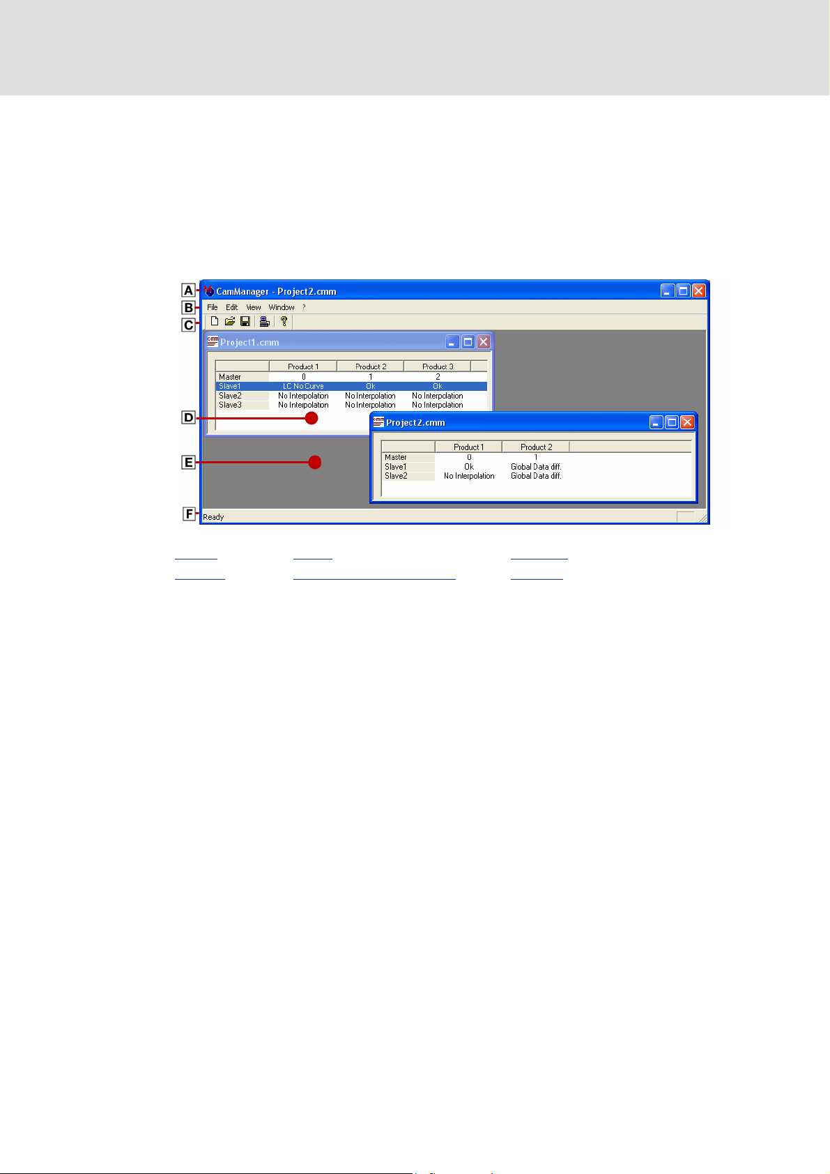
The user interface »Cam Manager« contains the following control and function elements:
Cam Designer Professional
User interface
Cam Manager
Title bar Toolbar Workspace
Menu bar Document window (worksheet) Status bar
L 3.0 EN - 08/2005 15
Cam Designer Professional
User interface
Cam Manager
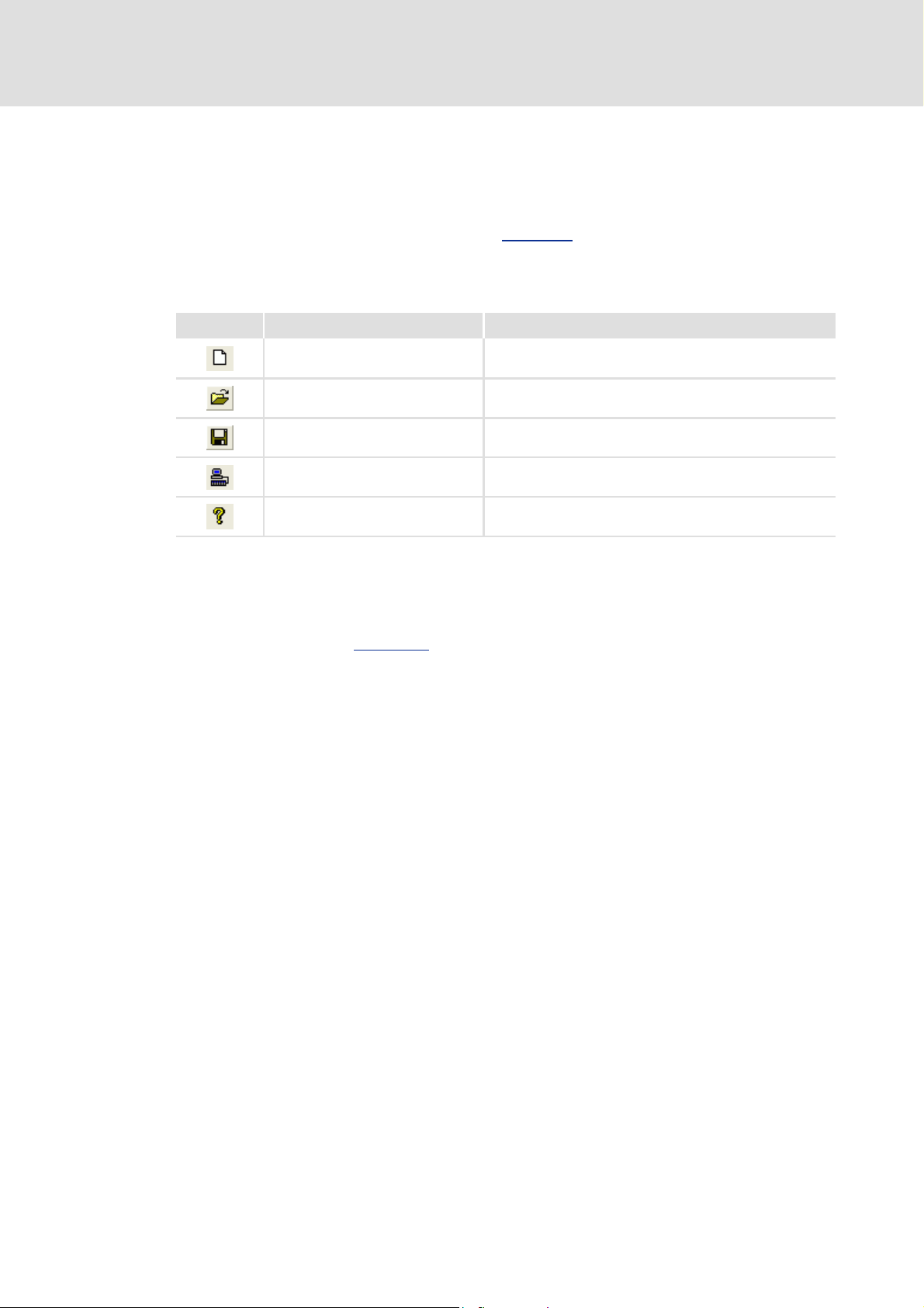
5.2.1 Toolbar
The display is optional.
Via the icons of the toolbar you can easily execute some of the most frequently used menu
commands without making a detour via the Menu bar
tions depends on the active mode/window.
Simply click an icon to activate the corresponding command.
Icon Menu command Function
FileNew Creates a new Cam Manager project.
FileOpen Opens a Cam Manager project.
FileSave Saves the project under the current name.
. The selection of the available func-
File
Connect to OPC Server
?Information on Cam Manger Opens a dialog box with version info
Establishes an online connection with the controllers.
Tip!
If you move the mouse pointer over an icon, a tool tip pops up providing a short information on the corresponding function. Moreover, an additional information is
displayed in the Status bar
.
16 3.0 EN - 08/2005 L
 Loading...