

Page 1
Automation Systems
Controller
Parameter setting and programming
_ _ _ _ _ _ _ _ _
Reference Manual EN
Ä.O+Kä
13461042
L
Page 2

Contents
_ _ _ _ _ _ _ _ _ _ _ _ _ _ _ _ _ _ _ _ _ _ _ _ _ _ _ _ _ _ _ _ _ _ _ _ _ _ _ _ _ _ _ _ _ _ _ _ _ _ _ _ _ _ _ _ _ _ _ _ _ _ _ _
1 About this documentation _ _ _ _ _ _ _ _ _ _ _ _ _ _ _ _ _ _ _ _ _ _ _ _ _ _ _ _ _ _ _ _ _ _ _ _ _ _ _ 6
1.1 Document history _ _ _ _ _ _ _ _ _ _ _ _ _ _ _ _ _ _ _ _ _ _ _ _ _ _ _ _ _ _ _ _ _ _ _ _ _ _ _ _ _ _ _ _ 9
1.2 Conventions used _ _ _ _ _ _ _ _ _ _ _ _ _ _ _ _ _ _ _ _ _ _ _ _ _ _ _ _ _ _ _ _ _ _ _ _ _ _ _ _ _ _ _ _ 10
1.3 Terminology used _ _ _ _ _ _ _ _ _ _ _ _ _ _ _ _ _ _ _ _ _ _ _ _ _ _ _ _ _ _ _ _ _ _ _ _ _ _ _ _ _ _ _ _ 11
1.4 Definition of the notes used _ _ _ _ _ _ _ _ _ _ _ _ _ _ _ _ _ _ _ _ _ _ _ _ _ _ _ _ _ _ _ _ _ _ _ _ _ _ 13
2Safety instructions _ _ _ _ _ _ _ _ _ _ _ _ _ _ _ _ _ _ _ _ _ _ _ _ _ _ _ _ _ _ _ _ _ _ _ _ _ _ _ _ _ _ _ _ 14
3 Controller-based Automation: Central motion control _ _ _ _ _ _ _ _ _ _ _ _ _ _ _ _ _ _ _ _ _ _ _ _ 15
4System structure _ _ _ _ _ _ _ _ _ _ _ _ _ _ _ _ _ _ _ _ _ _ _ _ _ _ _ _ _ _ _ _ _ _ _ _ _ _ _ _ _ _ _ _ _ 18
4.1 Engineering tools _ _ _ _ _ _ _ _ _ _ _ _ _ _ _ _ _ _ _ _ _ _ _ _ _ _ _ _ _ _ _ _ _ _ _ _ _ _ _ _ _ _ _ _ 20
4.2 Controller: The control centre of the Controller-based Automation _ _ _ _ _ _ _ _ _ _ _ _ _ _ _ _ _ 22
4.3 Runtime software of the Lenze Controllers _ _ _ _ _ _ _ _ _ _ _ _ _ _ _ _ _ _ _ _ _ _ _ _ _ _ _ _ _ _ 24
4.3.1 "Logic" runtime software _ _ _ _ _ _ _ _ _ _ _ _ _ _ _ _ _ _ _ _ _ _ _ _ _ _ _ _ _ _ _ _ _ _ _ 25
4.3.2 "Motion" runtime software _ _ _ _ _ _ _ _ _ _ _ _ _ _ _ _ _ _ _ _ _ _ _ _ _ _ _ _ _ _ _ _ _ _ 25
4.3.3 "Visu" runtime software _ _ _ _ _ _ _ _ _ _ _ _ _ _ _ _ _ _ _ _ _ _ _ _ _ _ _ _ _ _ _ _ _ _ _ _ 26
4.3.3.1 Sample topology 1: External monitor panel/display for
cabinet controllers _ _ _ _ _ _ _ _ _ _ _ _ _ _ _ _ _ _ _ _ _ _ _ _ _ _ _ _ _ _ _ _ _ 27
4.3.3.2 Sample topology 2: Separate control and visualisation _ _ _ _ _ _ _ _ _ _ _ _ _ 28
4.3.3.3 Sample topology 3: Independent control and visualisation
(CANopen) _ _ _ _ _ _ _ _ _ _ _ _ _ _ _ _ _ _ _ _ _ _ _ _ _ _ _ _ _ _ _ _ _ _ _ _ _ 29
5 Commissioning the controller _ _ _ _ _ _ _ _ _ _ _ _ _ _ _ _ _ _ _ _ _ _ _ _ _ _ _ _ _ _ _ _ _ _ _ _ _ 30
5.1 Identification _ _ _ _ _ _ _ _ _ _ _ _ _ _ _ _ _ _ _ _ _ _ _ _ _ _ _ _ _ _ _ _ _ _ _ _ _ _ _ _ _ _ _ _ _ _ _ 31
5.2 Control elements of the controllers _ _ _ _ _ _ _ _ _ _ _ _ _ _ _ _ _ _ _ _ _ _ _ _ _ _ _ _ _ _ _ _ _ _ 31
5.3 Starting the controller _ _ _ _ _ _ _ _ _ _ _ _ _ _ _ _ _ _ _ _ _ _ _ _ _ _ _ _ _ _ _ _ _ _ _ _ _ _ _ _ _ _ 32
5.4 Configuring the controller _ _ _ _ _ _ _ _ _ _ _ _ _ _ _ _ _ _ _ _ _ _ _ _ _ _ _ _ _ _ _ _ _ _ _ _ _ _ _ 33
5.4.1 Establishing an automatic dial-up connection _ _ _ _ _ _ _ _ _ _ _ _ _ _ _ _ _ _ _ _ _ _ _ _ 33
5.4.2 Entering the IP address of the controller _ _ _ _ _ _ _ _ _ _ _ _ _ _ _ _ _ _ _ _ _ _ _ _ _ _ _ 33
5.4.2.1 Cabinet controllers with external monitor panels (3231 C/3241 C) _ _ _ _ _ _ 34
5.4.2.2 Cabinet Controller without external monitor panel (c300/3221 C) _ _ _ _ _ _ 35
5.4.3 Specifying the IP address of the controller via file (optional) _ _ _ _ _ _ _ _ _ _ _ _ _ _ _ _ 36
5.4.4 Establishing Windows® CE access rights _ _ _ _ _ _ _ _ _ _ _ _ _ _ _ _ _ _ _ _ _ _ _ _ _ _ _ 37
5.4.4.1 Setting up Windows® CE users in »WebConfig« _ _ _ _ _ _ _ _ _ _ _ _ _ _ _ _ _ 37
5.4.5 Using your own wallpaper on the controller (Windows® CE) _ _ _ _ _ _ _ _ _ _ _ _ _ _ _ _ 38
5.5 I/O system 1000 at the backplane bus of a cabinet controller _ _ _ _ _ _ _ _ _ _ _ _ _ _ _ _ _ _ _ _ 39
5.5.1 Configuring I/O modules at the backplane bus _ _ _ _ _ _ _ _ _ _ _ _ _ _ _ _ _ _ _ _ _ _ _ 39
5.5.2 Determining the topology of the I/O modules automatically _ _ _ _ _ _ _ _ _ _ _ _ _ _ _ _ 41
5.6 Tabs of the I/O modules at the backplane bus _ _ _ _ _ _ _ _ _ _ _ _ _ _ _ _ _ _ _ _ _ _ _ _ _ _ _ _ _ 42
5.7 Error messages (backplane bus) _ _ _ _ _ _ _ _ _ _ _ _ _ _ _ _ _ _ _ _ _ _ _ _ _ _ _ _ _ _ _ _ _ _ _ _ 43
2 Lenze · Controller | Parameter setting & programming · Reference Manual · DMS 1.5 EN · 04/2014 · TD17
Page 3

Contents
_ _ _ _ _ _ _ _ _ _ _ _ _ _ _ _ _ _ _ _ _ _ _ _ _ _ _ _ _ _ _ _ _ _ _ _ _ _ _ _ _ _ _ _ _ _ _ _ _ _ _ _ _ _ _ _ _ _ _ _ _ _ _ _
6 Parameter setting using »WebConfig« _ _ _ _ _ _ _ _ _ _ _ _ _ _ _ _ _ _ _ _ _ _ _ _ _ _ _ _ _ _ _ _ _ 45
6.1 System structure _ _ _ _ _ _ _ _ _ _ _ _ _ _ _ _ _ _ _ _ _ _ _ _ _ _ _ _ _ _ _ _ _ _ _ _ _ _ _ _ _ _ _ _ _ 45
6.2 Parameterising the controller _ _ _ _ _ _ _ _ _ _ _ _ _ _ _ _ _ _ _ _ _ _ _ _ _ _ _ _ _ _ _ _ _ _ _ _ _ _ 45
6.3 Online connection from the Engineering PC to the controller _ _ _ _ _ _ _ _ _ _ _ _ _ _ _ _ _ _ _ _ 46
6.3.1 Setting IP addresses on the Engineering PC (example: Windows® XP) _ _ _ _ _ _ _ _ _ _ _ 46
6.4 Start »WebConfig« _ _ _ _ _ _ _ _ _ _ _ _ _ _ _ _ _ _ _ _ _ _ _ _ _ _ _ _ _ _ _ _ _ _ _ _ _ _ _ _ _ _ _ 47
6.5 User interface of »WebConfig« _ _ _ _ _ _ _ _ _ _ _ _ _ _ _ _ _ _ _ _ _ _ _ _ _ _ _ _ _ _ _ _ _ _ _ _ _ 48
6.5.1 Device parameters of the controller _ _ _ _ _ _ _ _ _ _ _ _ _ _ _ _ _ _ _ _ _ _ _ _ _ _ _ _ _ 50
6.5.2 Diagnostic/device commands _ _ _ _ _ _ _ _ _ _ _ _ _ _ _ _ _ _ _ _ _ _ _ _ _ _ _ _ _ _ _ _ _ 51
6.5.3 Logbook _ _ _ _ _ _ _ _ _ _ _ _ _ _ _ _ _ _ _ _ _ _ _ _ _ _ _ _ _ _ _ _ _ _ _ _ _ _ _ _ _ _ _ _ _ 52
6.5.3.1 Structure of a logbook entry: example _ _ _ _ _ _ _ _ _ _ _ _ _ _ _ _ _ _ _ _ _ _ 52
6.5.3.2 Filter options _ _ _ _ _ _ _ _ _ _ _ _ _ _ _ _ _ _ _ _ _ _ _ _ _ _ _ _ _ _ _ _ _ _ _ _ 53
6.5.3.3 Time filter for the display of logbook entries _ _ _ _ _ _ _ _ _ _ _ _ _ _ _ _ _ _ 53
6.5.3.4 Saving log files with mains failure protection _ _ _ _ _ _ _ _ _ _ _ _ _ _ _ _ _ _ 54
6.5.3.5 Export logbook entries _ _ _ _ _ _ _ _ _ _ _ _ _ _ _ _ _ _ _ _ _ _ _ _ _ _ _ _ _ _ 54
6.5.4 Device commands _ _ _ _ _ _ _ _ _ _ _ _ _ _ _ _ _ _ _ _ _ _ _ _ _ _ _ _ _ _ _ _ _ _ _ _ _ _ _ 55
6.5.5 User management _ _ _ _ _ _ _ _ _ _ _ _ _ _ _ _ _ _ _ _ _ _ _ _ _ _ _ _ _ _ _ _ _ _ _ _ _ _ _ 55
6.5.6 General parameters _ _ _ _ _ _ _ _ _ _ _ _ _ _ _ _ _ _ _ _ _ _ _ _ _ _ _ _ _ _ _ _ _ _ _ _ _ _ 55
6.5.7 Parameters of the communication cards _ _ _ _ _ _ _ _ _ _ _ _ _ _ _ _ _ _ _ _ _ _ _ _ _ _ _ 56
6.5.7.1 CAN communication card (MC-CAN2) _ _ _ _ _ _ _ _ _ _ _ _ _ _ _ _ _ _ _ _ _ _ 56
6.5.7.2 Optional PROFIBUS/PROFINET communication cards _ _ _ _ _ _ _ _ _ _ _ _ _ _ 57
6.5.8 Automatic update _ _ _ _ _ _ _ _ _ _ _ _ _ _ _ _ _ _ _ _ _ _ _ _ _ _ _ _ _ _ _ _ _ _ _ _ _ _ _ 57
6.5.9 Language selection _ _ _ _ _ _ _ _ _ _ _ _ _ _ _ _ _ _ _ _ _ _ _ _ _ _ _ _ _ _ _ _ _ _ _ _ _ _ _ 57
6.5.10 Parameter list buttons _ _ _ _ _ _ _ _ _ _ _ _ _ _ _ _ _ _ _ _ _ _ _ _ _ _ _ _ _ _ _ _ _ _ _ _ _ 57
7 Programming with the »PLC Designer« _ _ _ _ _ _ _ _ _ _ _ _ _ _ _ _ _ _ _ _ _ _ _ _ _ _ _ _ _ _ _ _ 58
7.1 System structure _ _ _ _ _ _ _ _ _ _ _ _ _ _ _ _ _ _ _ _ _ _ _ _ _ _ _ _ _ _ _ _ _ _ _ _ _ _ _ _ _ _ _ _ _ 59
7.2 Function blocks _ _ _ _ _ _ _ _ _ _ _ _ _ _ _ _ _ _ _ _ _ _ _ _ _ _ _ _ _ _ _ _ _ _ _ _ _ _ _ _ _ _ _ _ _ 60
7.3 Configuring and parameterising the controller using the control application _ _ _ _ _ _ _ _ _ _ _ _ 61
7.4 Controller c300/p300: Access to odd Controller addresses _ _ _ _ _ _ _ _ _ _ _ _ _ _ _ _ _ _ _ _ _ _ 62
7.5 Creating remanent variables (retain/persistent) _ _ _ _ _ _ _ _ _ _ _ _ _ _ _ _ _ _ _ _ _ _ _ _ _ _ _ 64
7.5.1 Storage of retain data on the SD card (only Controllers 3221 C/3231 C) _ _ _ _ _ _ _ _ _ _ 65
8»Backup & Restore« (data backup/restore) _ _ _ _ _ _ _ _ _ _ _ _ _ _ _ _ _ _ _ _ _ _ _ _ _ _ _ _ _ _ 67
9 Data integrity in the event of a voltage failure _ _ _ _ _ _ _ _ _ _ _ _ _ _ _ _ _ _ _ _ _ _ _ _ _ _ _ _ 68
9.1 UPS functionality of the controllers _ _ _ _ _ _ _ _ _ _ _ _ _ _ _ _ _ _ _ _ _ _ _ _ _ _ _ _ _ _ _ _ _ _ 68
9.1.1 Internal UPS (for Controllers without UPS connection) _ _ _ _ _ _ _ _ _ _ _ _ _ _ _ _ _ _ _ 68
9.1.2 External UPS (for Controllers 3241 C with UPS connection) _ _ _ _ _ _ _ _ _ _ _ _ _ _ _ _ _ 69
9.2 Storage of »VisiWinNET® Smart« visualisation data _ _ _ _ _ _ _ _ _ _ _ _ _ _ _ _ _ _ _ _ _ _ _ _ _ 70
9.3 Storage of retain/persistent variables of the PLC _ _ _ _ _ _ _ _ _ _ _ _ _ _ _ _ _ _ _ _ _ _ _ _ _ _ _ 71
10 Device replacement - replacing the controller (in the event of service) _ _ _ _ _ _ _ _ _ _ _ _ _ _ _ 72
10.1 Removing the connected (defective) controller _ _ _ _ _ _ _ _ _ _ _ _ _ _ _ _ _ _ _ _ _ _ _ _ _ _ _ _ 72
10.2 Connecting the new controller/replacement device _ _ _ _ _ _ _ _ _ _ _ _ _ _ _ _ _ _ _ _ _ _ _ _ _ 73
10.3 After the device replacement: Automatic data update _ _ _ _ _ _ _ _ _ _ _ _ _ _ _ _ _ _ _ _ _ _ _ _ 75
10.4 Subsequent use of retain data on the new controller _ _ _ _ _ _ _ _ _ _ _ _ _ _ _ _ _ _ _ _ _ _ _ _ _ 77
10.5 Error messages after a device replacement _ _ _ _ _ _ _ _ _ _ _ _ _ _ _ _ _ _ _ _ _ _ _ _ _ _ _ _ _ _ 78
Lenze · Controller | Parameter setting & programming · Reference Manual · DMS 1.5 EN · 04/2014 · TD17 3
Page 4

Contents
_ _ _ _ _ _ _ _ _ _ _ _ _ _ _ _ _ _ _ _ _ _ _ _ _ _ _ _ _ _ _ _ _ _ _ _ _ _ _ _ _ _ _ _ _ _ _ _ _ _ _ _ _ _ _ _ _ _ _ _ _ _ _ _
11 Remote maintenance and diagnostics _ _ _ _ _ _ _ _ _ _ _ _ _ _ _ _ _ _ _ _ _ _ _ _ _ _ _ _ _ _ _ _ _ 79
11.1 Status LEDs of the Controllers _ _ _ _ _ _ _ _ _ _ _ _ _ _ _ _ _ _ _ _ _ _ _ _ _ _ _ _ _ _ _ _ _ _ _ _ _ 80
11.2 Diagnostics via Telnet _ _ _ _ _ _ _ _ _ _ _ _ _ _ _ _ _ _ _ _ _ _ _ _ _ _ _ _ _ _ _ _ _ _ _ _ _ _ _ _ _ _ 82
11.2.1 »WebConfig« settings _ _ _ _ _ _ _ _ _ _ _ _ _ _ _ _ _ _ _ _ _ _ _ _ _ _ _ _ _ _ _ _ _ _ _ _ _ 83
11.3 Data transfer via FTP _ _ _ _ _ _ _ _ _ _ _ _ _ _ _ _ _ _ _ _ _ _ _ _ _ _ _ _ _ _ _ _ _ _ _ _ _ _ _ _ _ _ 85
11.3.1 FTP settings with the »WebConfig« _ _ _ _ _ _ _ _ _ _ _ _ _ _ _ _ _ _ _ _ _ _ _ _ _ _ _ _ _ _ 86
11.3.2 FTP and web settings in the Internet Explorer _ _ _ _ _ _ _ _ _ _ _ _ _ _ _ _ _ _ _ _ _ _ _ _ 87
11.4 Diagnostics with the logbook _ _ _ _ _ _ _ _ _ _ _ _ _ _ _ _ _ _ _ _ _ _ _ _ _ _ _ _ _ _ _ _ _ _ _ _ _ _ 89
11.4.1 Logbook query via »WebConfig« _ _ _ _ _ _ _ _ _ _ _ _ _ _ _ _ _ _ _ _ _ _ _ _ _ _ _ _ _ _ _ 90
11.4.2 Logbook parameters _ _ _ _ _ _ _ _ _ _ _ _ _ _ _ _ _ _ _ _ _ _ _ _ _ _ _ _ _ _ _ _ _ _ _ _ _ _ 91
11.5 Activate Windows® CE interface _ _ _ _ _ _ _ _ _ _ _ _ _ _ _ _ _ _ _ _ _ _ _ _ _ _ _ _ _ _ _ _ _ _ _ _ 92
11.5.1 Remote Display: Remote control of Controller via Internet or LAN _ _ _ _ _ _ _ _ _ _ _ _ _ 94
11.5.2 Virtual Network Computing (VNC) _ _ _ _ _ _ _ _ _ _ _ _ _ _ _ _ _ _ _ _ _ _ _ _ _ _ _ _ _ _ 95
12 Visualisation with »VisiWinNET®« _ _ _ _ _ _ _ _ _ _ _ _ _ _ _ _ _ _ _ _ _ _ _ _ _ _ _ _ _ _ _ _ _ _ _ 96
12.1 Visualisation on the controller: local and remote _ _ _ _ _ _ _ _ _ _ _ _ _ _ _ _ _ _ _ _ _ _ _ _ _ _ _ 97
12.2 System structure _ _ _ _ _ _ _ _ _ _ _ _ _ _ _ _ _ _ _ _ _ _ _ _ _ _ _ _ _ _ _ _ _ _ _ _ _ _ _ _ _ _ _ _ _ 98
12.3 Using the visualisation to access data of the control/parameters _ _ _ _ _ _ _ _ _ _ _ _ _ _ _ _ _ _ 99
12.4 Use the Direct driver "LogicAndMotionV3" (local visualisation) _ _ _ _ _ _ _ _ _ _ _ _ _ _ _ _ _ _ _ 101
12.4.1 Selecting the target device using the Windows® CE operating system
(example 3200 C/p500) _ _ _ _ _ _ _ _ _ _ _ _ _ _ _ _ _ _ _ _ _ _ _ _ _ _ _ _ _ _ _ _ _ _ _ _ 102
12.4.2 Project Explorer _ _ _ _ _ _ _ _ _ _ _ _ _ _ _ _ _ _ _ _ _ _ _ _ _ _ _ _ _ _ _ _ _ _ _ _ _ _ _ _ 104
12.4.3 Using the variables browser to access variables (browse variables) _ _ _ _ _ _ _ _ _ _ _ _ 105
12.4.4 Accept variable definitions to project _ _ _ _ _ _ _ _ _ _ _ _ _ _ _ _ _ _ _ _ _ _ _ _ _ _ _ _ _ 107
12.4.5 Creating control elements/linking them to variables _ _ _ _ _ _ _ _ _ _ _ _ _ _ _ _ _ _ _ _ 108
12.4.6 Transferring an application to the target device _ _ _ _ _ _ _ _ _ _ _ _ _ _ _ _ _ _ _ _ _ _ _ 109
12.4.7 Start the »VisiWinNET®« _ _ _ _ _ _ _ _ _ _ _ _ _ _ _ _ _ _ _ _ _ _ _ _ _ _ _ _ _ _ _ _ _ _ _ 110
12.5 Using the LogicAndMotionV3 direct driver (remote access) _ _ _ _ _ _ _ _ _ _ _ _ _ _ _ _ _ _ _ _ _ 111
12.6 OPC tunnel for local visualisation (integrated control system) _ _ _ _ _ _ _ _ _ _ _ _ _ _ _ _ _ _ _ _ 112
12.6.1 Integrating the OPC tunnel in »VisiWinNET®« _ _ _ _ _ _ _ _ _ _ _ _ _ _ _ _ _ _ _ _ _ _ _ _ 113
12.6.2 Browsing variable definitions / configuring the device _ _ _ _ _ _ _ _ _ _ _ _ _ _ _ _ _ _ _ 114
12.6.3 Manual integration of variables (experts only - background knowledge required!) _ _ _ _ 116
12.6.4 Configure OPC tunnel _ _ _ _ _ _ _ _ _ _ _ _ _ _ _ _ _ _ _ _ _ _ _ _ _ _ _ _ _ _ _ _ _ _ _ _ _ 119
12.7 OPC tunnel for external visualisation (remote access) _ _ _ _ _ _ _ _ _ _ _ _ _ _ _ _ _ _ _ _ _ _ _ _ 120
12.7.1 Windows® CE operating system _ _ _ _ _ _ _ _ _ _ _ _ _ _ _ _ _ _ _ _ _ _ _ _ _ _ _ _ _ _ _ 120
12.7.1.1 Configure OPC tunnel for remote access (Windows® CE) _ _ _ _ _ _ _ _ _ _ _ _ 121
12.7.2 Windows® XP/XP Embedded operating system _ _ _ _ _ _ _ _ _ _ _ _ _ _ _ _ _ _ _ _ _ _ _ 122
12.7.2.1 Configure OPC tunnel for remote access (Windows® XP/XP Embedded) _ _ _ 123
12.7.3 Browsing variables _ _ _ _ _ _ _ _ _ _ _ _ _ _ _ _ _ _ _ _ _ _ _ _ _ _ _ _ _ _ _ _ _ _ _ _ _ _ _ 124
12.8 Lenze specifications _ _ _ _ _ _ _ _ _ _ _ _ _ _ _ _ _ _ _ _ _ _ _ _ _ _ _ _ _ _ _ _ _ _ _ _ _ _ _ _ _ _ _ 126
12.8.1 Install additional fonts _ _ _ _ _ _ _ _ _ _ _ _ _ _ _ _ _ _ _ _ _ _ _ _ _ _ _ _ _ _ _ _ _ _ _ _ _ 126
12.8.2 Timeout (waiting position) of the CAN OPC server influences the time response of the
visualisation _ _ _ _ _ _ _ _ _ _ _ _ _ _ _ _ _ _ _ _ _ _ _ _ _ _ _ _ _ _ _ _ _ _ _ _ _ _ _ _ _ _ 126
4 Lenze · Controller | Parameter setting & programming · Reference Manual · DMS 1.5 EN · 04/2014 · TD17
Page 5

Contents
_ _ _ _ _ _ _ _ _ _ _ _ _ _ _ _ _ _ _ _ _ _ _ _ _ _ _ _ _ _ _ _ _ _ _ _ _ _ _ _ _ _ _ _ _ _ _ _ _ _ _ _ _ _ _ _ _ _ _ _ _ _ _ _
13 Parameter reference _ _ _ _ _ _ _ _ _ _ _ _ _ _ _ _ _ _ _ _ _ _ _ _ _ _ _ _ _ _ _ _ _ _ _ _ _ _ _ _ _ _ _ 127
13.1 Structure of the parameter description _ _ _ _ _ _ _ _ _ _ _ _ _ _ _ _ _ _ _ _ _ _ _ _ _ _ _ _ _ _ _ _ 128
13.1.1 Data types _ _ _ _ _ _ _ _ _ _ _ _ _ _ _ _ _ _ _ _ _ _ _ _ _ _ _ _ _ _ _ _ _ _ _ _ _ _ _ _ _ _ _ 128
13.1.2 Parameters with read access _ _ _ _ _ _ _ _ _ _ _ _ _ _ _ _ _ _ _ _ _ _ _ _ _ _ _ _ _ _ _ _ _ 129
13.1.3 Parameters with write access _ _ _ _ _ _ _ _ _ _ _ _ _ _ _ _ _ _ _ _ _ _ _ _ _ _ _ _ _ _ _ _ _ 129
13.1.3.1 Parameters with a setting range _ _ _ _ _ _ _ _ _ _ _ _ _ _ _ _ _ _ _ _ _ _ _ _ _ 129
13.1.3.2 Parameters with a selection list _ _ _ _ _ _ _ _ _ _ _ _ _ _ _ _ _ _ _ _ _ _ _ _ _ 129
13.1.3.3 Parameters with a bit-coded setting _ _ _ _ _ _ _ _ _ _ _ _ _ _ _ _ _ _ _ _ _ _ _ 130
13.1.4 Parameter attributes _ _ _ _ _ _ _ _ _ _ _ _ _ _ _ _ _ _ _ _ _ _ _ _ _ _ _ _ _ _ _ _ _ _ _ _ _ _ 130
13.2 Basic parameters of the Controllers 3200 C/c300 and p300/p500 _ _ _ _ _ _ _ _ _ _ _ _ _ _ _ _ _ _ 131
13.3 Voltage buffering by external UPS (optional, for Controller 3241 C) _ _ _ _ _ _ _ _ _ _ _ _ _ _ _ _ _ 158
13.4 Ethernet (on board) _ _ _ _ _ _ _ _ _ _ _ _ _ _ _ _ _ _ _ _ _ _ _ _ _ _ _ _ _ _ _ _ _ _ _ _ _ _ _ _ _ _ _ 161
13.5 EtherCAT _ _ _ _ _ _ _ _ _ _ _ _ _ _ _ _ _ _ _ _ _ _ _ _ _ _ _ _ _ _ _ _ _ _ _ _ _ _ _ _ _ _ _ _ _ _ _ _ _ 163
13.6 Monitor panel (integrated/external) _ _ _ _ _ _ _ _ _ _ _ _ _ _ _ _ _ _ _ _ _ _ _ _ _ _ _ _ _ _ _ _ _ _ 168
13.7 PLC (Logic/Motion) _ _ _ _ _ _ _ _ _ _ _ _ _ _ _ _ _ _ _ _ _ _ _ _ _ _ _ _ _ _ _ _ _ _ _ _ _ _ _ _ _ _ _ 172
13.8 Backup&Restore _ _ _ _ _ _ _ _ _ _ _ _ _ _ _ _ _ _ _ _ _ _ _ _ _ _ _ _ _ _ _ _ _ _ _ _ _ _ _ _ _ _ _ _ _ 174
13.9 Communication cards: optional interface _ _ _ _ _ _ _ _ _ _ _ _ _ _ _ _ _ _ _ _ _ _ _ _ _ _ _ _ _ _ _ 178
13.9.1 CAN (MC-CAN2) communication card / CAN interface for Controller c300/p300 _ _ _ _ _ 179
13.9.2 PROFIBUS and PROFINET communication cards _ _ _ _ _ _ _ _ _ _ _ _ _ _ _ _ _ _ _ _ _ _ _ 185
Index _ _ _ _ _ _ _ _ _ _ _ _ _ _ _ _ _ _ _ _ _ _ _ _ _ _ _ _ _ _ _ _ _ _ _ _ _ _ _ _ _ _ _ _ _ _ _ _ _ _ _ 187
Your opinion is important to us _ _ _ _ _ _ _ _ _ _ _ _ _ _ _ _ _ _ _ _ _ _ _ _ _ _ _ _ _ _ _ _ _ _ _ _ _ 194
Lenze · Controller | Parameter setting & programming · Reference Manual · DMS 1.5 EN · 04/2014 · TD17 5
Page 6

1 About this documentation
_ _ _ _ _ _ _ _ _ _ _ _ _ _ _ _ _ _ _ _ _ _ _ _ _ _ _ _ _ _ _ _ _ _ _ _ _ _ _ _ _ _ _ _ _ _ _ _ _ _ _ _ _ _ _ _ _ _ _ _ _ _ _ _
1 About this documentation
This documentation contains general information on how to parameterise, configure and diagnose
the Lenze Controllers.
This manual is part of the "Controller-based Automation" manual collection. It consists of the
following sets of documentation:
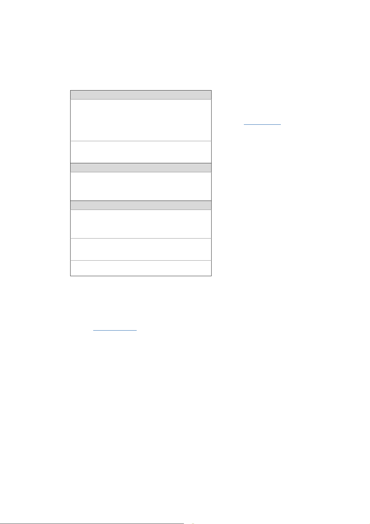
Documentation type Subject
System manuals System overview/sample topologies
• Controller-based Automation
• Visualization
Communication manuals
Online helps
Reference manuals
Online helps
Software manuals
Online helps
Bus systems
• Controller-based Automation EtherCAT®
• Controller-based Automation CANopen®
• Controller-based Automation PROFIBUS®
• Controller-based Automation PROFINET®
Lenze Controller:
• Controller 3200 C
• Controller c300
• Controller p300
• Controller p500
Lenze Engineering Tools:
• »PLC Designer«: Programming
• »Engineer«: Inverter configuration
• »VisiWinNET® Smart«: Visualisation
• »Backup & Restore«: Back up/restore data
Information on how to use the controllers outside the control technology can be found
in the system manuals created for the prevailing application case.
Lenze · Controller | Parameter setting & programming · Reference Manual · DMS 1.5 EN · 04/2014 · TD17 6
Page 7
1 About this documentation
_ _ _ _ _ _ _ _ _ _ _ _ _ _ _ _ _ _ _ _ _ _ _ _ _ _ _ _ _ _ _ _ _ _ _ _ _ _ _ _ _ _ _ _ _ _ _ _ _ _ _ _ _ _ _ _ _ _ _ _ _ _ _ _
More technical documentation for Lenze components
Further information on Lenze products which can be used in conjunction with Controller-based
Automation can be found in the following sets of documentation:
Mounting & wiring Symbols:
Mounting instructions
• Controller
• Communication cards (MC-xxx)
• I/O system 1000 (EPM-Sxxx)
• Inverter, Servo Drives
•Communication modules
Operating instructions
• Controller
• Servo system ECS (ECSxE, ECSxM)
Sample applications/Using application templates
Online help/software manuals
• Application Sample i700
• Application Samples
• ApplicationTemplate
Parameterisation, configuration, commissioning
Online help/reference manuals
• Controller
• Inverter, Servo Drives
• I/O system 1000 (EPM-Sxxx)
Online help/communication manuals
• Bus systems
•Communication modules
Operating instructions
• Servo system ECS (ECSxE, ECSxM)
Printed documentation
Online help in the Lenze Engineering
Tool (also available as PDF file at
www.lenze.com
.)
Tip!
Current documentation and software updates with regard to Lenze products can be found
in the download area at:
www.lenze.com
Target group
This documentation is intended for persons who commission and maintain a Controller-based
automation system by means of a Lenze Controller and the »PLC Designer« engineering tool.
Screenshots/application examples
All screenshots in this documentation are application examples. Depending on the firmware
version of the field devices and the software version of the Engineering tools installed (e.g. »PLC
Designer« ), screenshots in this documentation may differ from the representation on the screen.
7 Lenze · Controller | Parameter setting & programming · Reference Manual · DMS 1.5 EN · 04/2014 · TD17
Page 8
1 About this documentation
_ _ _ _ _ _ _ _ _ _ _ _ _ _ _ _ _ _ _ _ _ _ _ _ _ _ _ _ _ _ _ _ _ _ _ _ _ _ _ _ _ _ _ _ _ _ _ _ _ _ _ _ _ _ _ _ _ _ _ _ _ _ _ _
Information regarding the validity
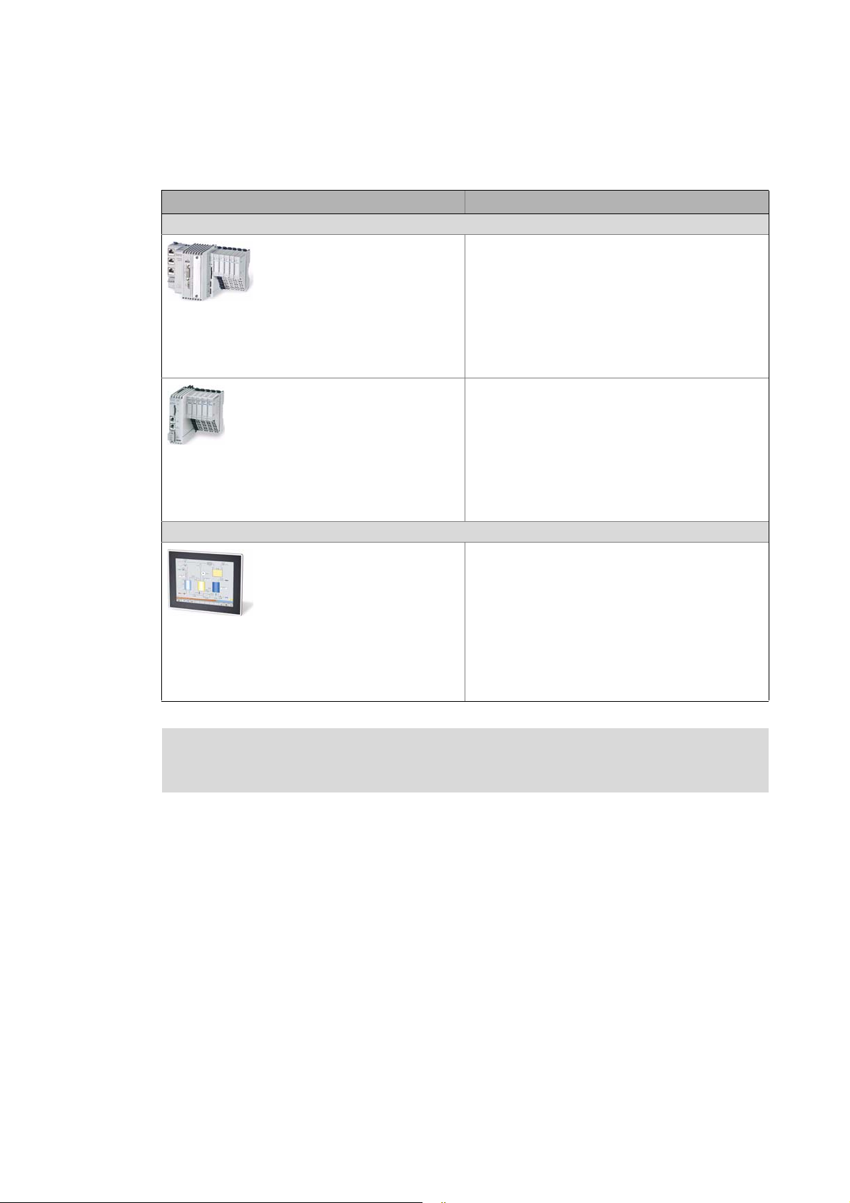
The information provided in this documentation is valid for the following Lenze Controllers:
Controller Versions
Cabinet Controller
• Controller 3221 C
• Controller 3231 C
• Controller 3241 C
Example: Controller 3241 C with connected I/O system 1000
• Controller c300
Example: Controller c300 with connected I/O system 1000
Panel Controller
• Controller p300
• Controller p500
Example: Controller p500
Operating instructions/mounting instructions of the Controllers
Here you will find technical data and information on how to install the devices.
Lenze · Controller | Parameter setting & programming · Reference Manual · DMS 1.5 EN · 04/2014 · TD17 8
Page 9

1 About this documentation
1.1 Document history
_ _ _ _ _ _ _ _ _ _ _ _ _ _ _ _ _ _ _ _ _ _ _ _ _ _ _ _ _ _ _ _ _ _ _ _ _ _ _ _ _ _ _ _ _ _ _ _ _ _ _ _ _ _ _ _ _ _ _ _ _ _ _ _
1.1 Document history
Version Description
1.0 10/2010 TD11 First edition for the Lenze automation system "Controller-based Automation" 3.x
1.1 04/2011 TD11 Update for the Lenze automation system "Controller-based Automation" 3.1
1.2 12/2011 TD11 Update for the Lenze automation system "Controller-based Automation" 3.2
1.3 05/2012 TD11 Update for the Lenze automation system "Controller-based Automation" 3.3
• Amended by Controllers p500 (panel controllers)
1.4 11/2012 TD11 Update for the Lenze automation system "Controller-based Automation" 3.6
• Controller c300/p300 added (in preparation)
1.5 04/2014 TD17 Update for the Lenze automation system "Controller-based Automation" 3.8
• Controller c300/p300
9
Lenze · Controller | Parameter setting & programming · Reference Manual · DMS 1.5 EN · 04/2014 · TD17
Page 10
1 About this documentation
1.2 Conventions used
_ _ _ _ _ _ _ _ _ _ _ _ _ _ _ _ _ _ _ _ _ _ _ _ _ _ _ _ _ _ _ _ _ _ _ _ _ _ _ _ _ _ _ _ _ _ _ _ _ _ _ _ _ _ _ _ _ _ _ _ _ _ _ _
1.2 Conventions used
This documentation uses the following conventions to distinguish between different types of
information:
Type of information Highlighting Examples/notes
Spelling of numbers
Decimal separators Point The decimal point is generally used.
For example: 1234.56
Text
Version information Text colour blue All pieces of information that only apply to or from a specific
Program name » « »PLC Designer«...
Window italics The message window... / The Options dialog box ...
Variable names Setting bEnable to TRUE...
Control element bold The OK button ... / The Copy command ... / The Properties tab
Sequence of menu
commands
Shortcut <bold> Use <F1> to open the online help.
Hyperlink underlined
Symbols
Page reference ( 10) Reference to further information: Page number in PDF file.
Step-by-step instructions
software version of the inverter are highlighted
correspondingly in this documentation.
Example: This function extension is available from software
version V3.0!
... / The Name input field ...
If several commands must be used in sequence to carry out a
function, the individual commands are separated by an
arrow: Select File
If a key combination is required for a command, a "+" is
placed between the key identifiers: With <Shift>+<ESC>...
Reference to further information: Hyperlink to further
information.
Step-by-step instructions are marked by a pictograph.
Open to...
Lenze · Controller | Parameter setting & programming · Reference Manual · DMS 1.5 EN · 04/2014 · TD17 10
Page 11
1 About this documentation
1.3 Terminology used
_ _ _ _ _ _ _ _ _ _ _ _ _ _ _ _ _ _ _ _ _ _ _ _ _ _ _ _ _ _ _ _ _ _ _ _ _ _ _ _ _ _ _ _ _ _ _ _ _ _ _ _ _ _ _ _ _ _ _ _ _ _ _ _
1.3 Terminology used
Term Meaning
Controller The controller is the central component of the automation system which controls the
Engineering PC The Engineering PC and the Engineering tools installed serve to configure and
Fieldbus stations Devices integrated in the bus system as, for instance, Controller and inverter
Field device
Inverter Generic term for Lenze frequency inverter, servo inverter
PLC Programmable Logic Controller
PLC Programmable Logic Controller (PLC)
UPS Uninterruptible power system (UPS)
Engineering tools
Software solutions for easy engineering in all phases which serve to commission, configure, parameterise and
diagnose the Lenze automation system.
Engineering tools
Logic and Motion functionalities by means of the runtime software.
The controller communicates with the field devices via the fieldbus.
parameterise the system "Controller-based Automation".
The Engineering PC communicates with the controller via Ethernet.
( 20)
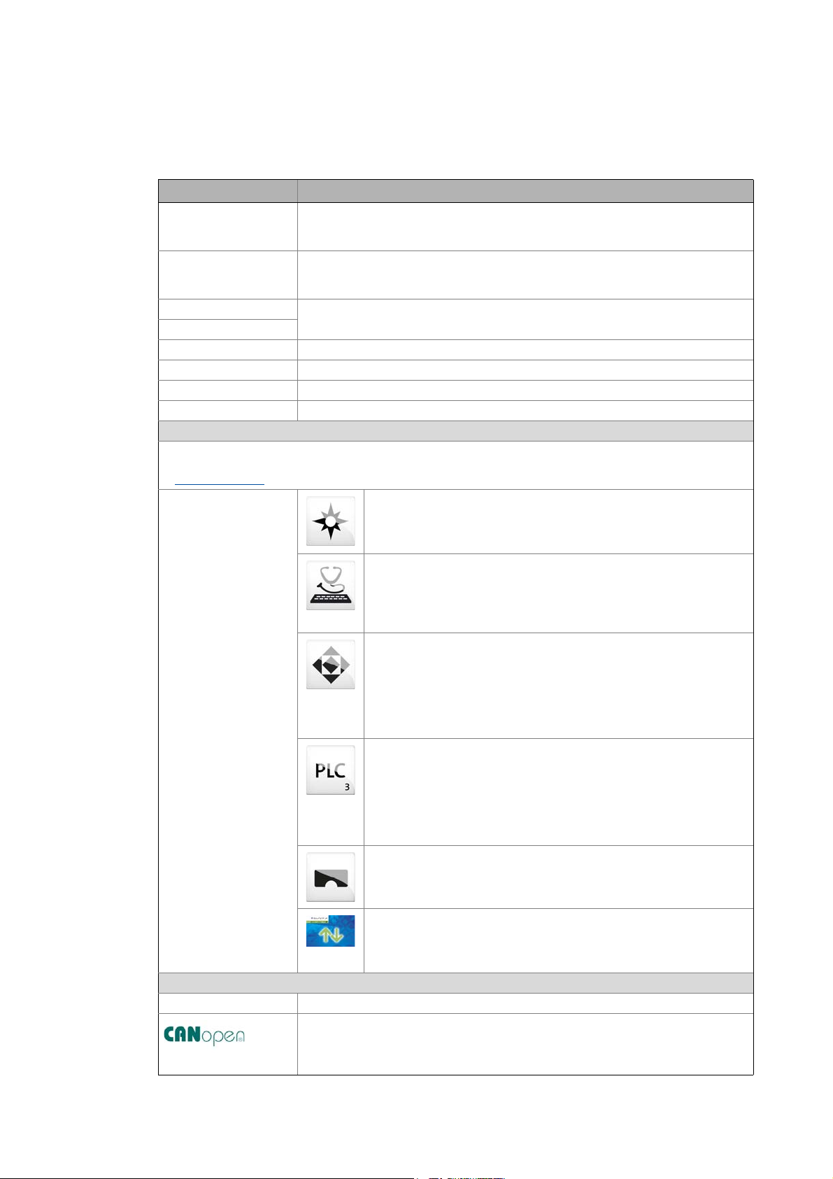
»EASY Navigator« – provides for orientation
• All convenient Lenze Engineering tools at a glance
• Tools can be selected quickly
• Simplifies the access to the engineering process by its clarity.
»EASY Starter« – easy-to-use tool for service technicians
• For the maintenance of Lenze devices
• For the commissioning of Lenze devices
• Online diagnostics, parameterisation and commissioning
• Loading of ready-to-use applications to the device
»Engineer« – multi-device engineering
• Suitable for all products of the Lenze portfolio
• Easy handling by means of graphical user interfaces
•
Can be used in all engineering phases (project planning, commissioning,
production)
• Parameterisation and configuration of Lenze devices
»PLC Designer« – programming processes
• Creating individual programs
• Programming Logic & Motion according to IEC 61131-3 (AWL, KOP, FUP,
ST, AS and CFC-Editor), based on CoDeSys V3
• Certified function blocks according to PLCopen part 1 + 2
• Graphic DIN 66025 Editor (G code) with DXF import
• Integrated visualisation for the simple representation of processes
»VisiWinNET« – visualisation tool
• Visualise the applications of the automation system
• Create the visualisation/user interface
11
»Backup & Restore« – back up/restore/update data
•Create data backups
• Restore data after device replacement
• Carry out software update of the Controller
Bus systems
CAN CAN (Controller Area Network) is an asynchronous, serial fieldbus system.
CANopen® is a communication protocol based on CAN. The Lenze system bus (CAN on
board) operates with a subset of this communication protocol.
CANopen® is a registered community trademark of the CAN user organisation CiA® (CAN
in Automation e. V.).
Lenze · Controller | Parameter setting & programming · Reference Manual · DMS 1.5 EN · 04/2014 · TD17
Page 12

1 About this documentation
1.3 Terminology used
_ _ _ _ _ _ _ _ _ _ _ _ _ _ _ _ _ _ _ _ _ _ _ _ _ _ _ _ _ _ _ _ _ _ _ _ _ _ _ _ _ _ _ _ _ _ _ _ _ _ _ _ _ _ _ _ _ _ _ _ _ _ _ _
Term Meaning
EtherCAT® (Ethernet for Controller and Automation Technology) is an Ethernet-based
fieldbus system which fulfils the application profile for industrial real-time systems.
EtherCAT® is a registered trademark and patented technology, licensed by Beckhoff
Automation GmbH, Germany.
PROFIBUS® (Process Field Bus) is a widely used fieldbus system for the automation of
machines and production lines.
PROFIBUS® is a registered trademark and patented technology licensed by the PROFIBUS
& PROFINET International (PI) user organisation.
PROFINET® (Process Field Network) is a real-time capable fieldbus system based on
Ethernet.
PROFINET® is a registered trademark and patented technology licensed by the PROFIBUS
& PROFINET International (PI) user organisation.
Lenze · Controller | Parameter setting & programming · Reference Manual · DMS 1.5 EN · 04/2014 · TD17 12
Page 13
1 About this documentation
1.4 Definition of the notes used
_ _ _ _ _ _ _ _ _ _ _ _ _ _ _ _ _ _ _ _ _ _ _ _ _ _ _ _ _ _ _ _ _ _ _ _ _ _ _ _ _ _ _ _ _ _ _ _ _ _ _ _ _ _ _ _ _ _ _ _ _ _ _ _
1.4 Definition of the notes used
This documentation uses the following signal words and symbols to indicate dangers and
important information:
Safety instructions
Structure of the safety instructions:
Pictograph and signal word!
(characterises the type and severity of danger)
Note
(describes the danger and informs how to prevent dangerous situations)
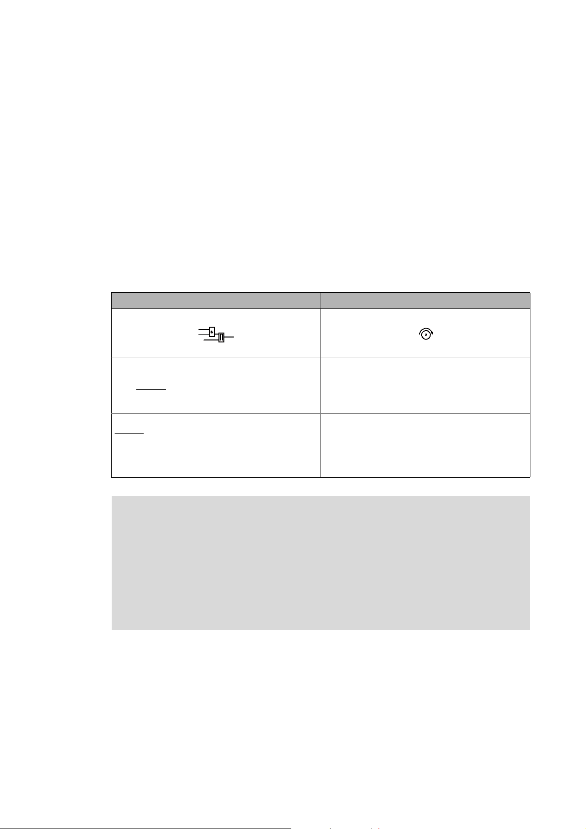
Pictograph Signal word Meaning
Danger! Danger of personal injuries through dangerous electrical voltage
Danger! Danger of personal injury through a general source of danger
Stop! Danger of material damage
Reference to an imminent danger that may result in death or serious personal
injury unless the corresponding measures are taken.
Reference to an imminent danger that may result in death or serious personal
injury unless the corresponding measures are taken.
Indicates a potential danger that may lead to material damage unless the
corresponding measures are taken.
Application notes
Pictograph Signal word Meaning
Note! Important note to ensure troublefree operation
Tip! Useful tip for easy handling
Reference to another document
13
Lenze · Controller | Parameter setting & programming · Reference Manual · DMS 1.5 EN · 04/2014 · TD17
Page 14

2 Safety instructions
_ _ _ _ _ _ _ _ _ _ _ _ _ _ _ _ _ _ _ _ _ _ _ _ _ _ _ _ _ _ _ _ _ _ _ _ _ _ _ _ _ _ _ _ _ _ _ _ _ _ _ _ _ _ _ _ _ _ _ _ _ _ _ _
2 Safety instructions
Please observe the following safety instructions when you want to commission an automation
system or a plant using a controller.
Read the documentation supplied with the corresponding field device thoroughly before
starting to commission the devices with the controller!
The device documentation contains safety instructions which must be observed!
Danger!
According to today's scientific knowledge it is not possible to ensure absolute freedom
from defects of a software.
If necessary, systems with built-in inverters must be provided with additional
monitoring and protective equipment complying with the relevant safety regulations
(e.g. law on technical equipment, regulations for the prevention of accidents) in each
case, so that an impermissible operating status does not endanger persons or facilities.
During commissioning persons must keep a safe distance from the motor or the
machine parts driven by the motor. Otherwise there would be a risk of injury by the
moving machine parts.
Stop!
If you change parameters in the engineering software while a device is connected online,
the changes will be directly accepted by the device.
A wrong parameter setting can cause unpredictable motor movements.
By an unintended direction of rotation, too high speed, or jerky operation, the driven
machine parts may be damaged.
Lenze · Controller | Parameter setting & programming · Reference Manual · DMS 1.5 EN · 04/2014 · TD17 14
Page 15
3 Controller-based Automation: Central motion control
_ _ _ _ _ _ _ _ _ _ _ _ _ _ _ _ _ _ _ _ _ _ _ _ _ _ _ _ _ _ _ _ _ _ _ _ _ _ _ _ _ _ _ _ _ _ _ _ _ _ _ _ _ _ _ _ _ _ _ _ _ _ _ _
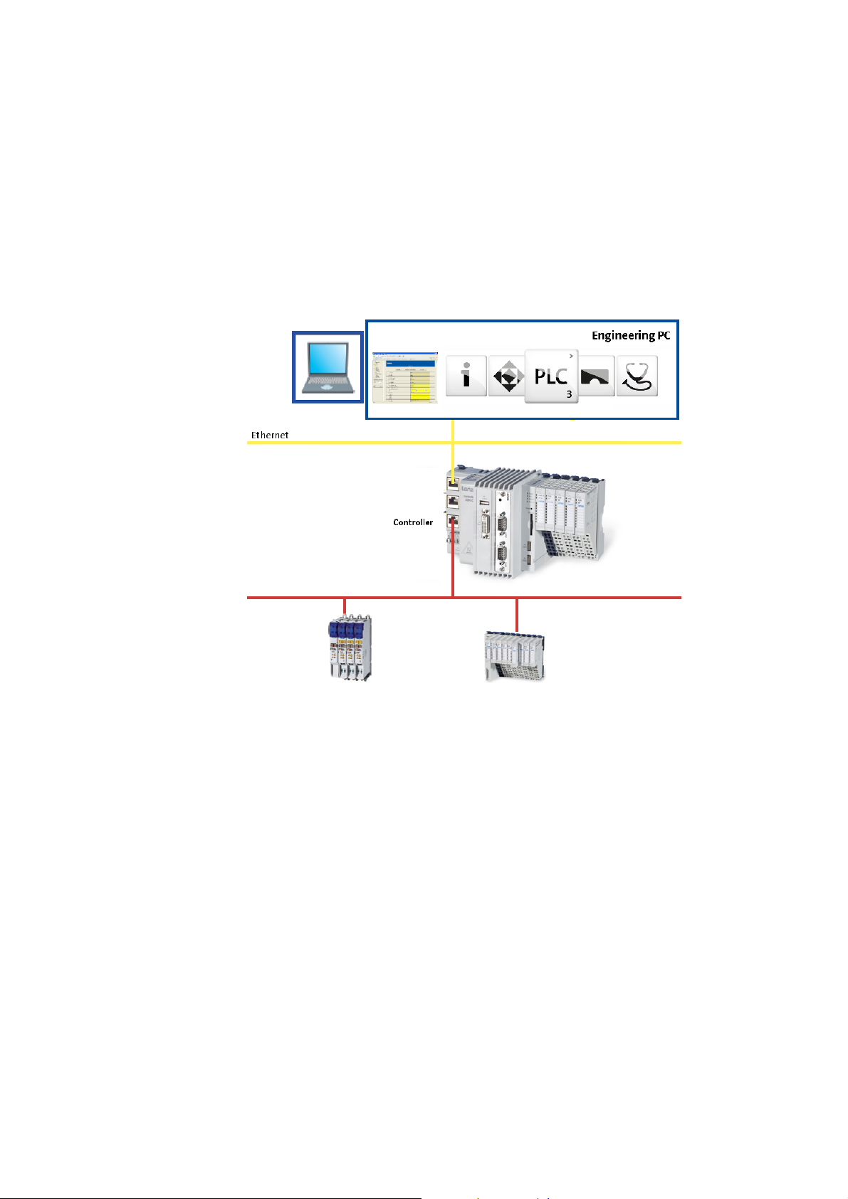
3 Controller-based Automation: Central motion control
The Lenze automation system "Controller-based Automation" serves to create complex automation
solutions with central motion control. Here, the Controller is the control centre of the system.
System structure of the Controller-based Automation: "All from one single source"
[3-1] Example configuration (EtherCAT bus system): Controller 3200 C with I/O system 1000 and Servo Inverter i700.
15 Lenze · Controller | Parameter setting & programming · Reference Manual · DMS 1.5 EN · 04/2014 · TD17
Page 16

3 Controller-based Automation: Central motion control
_ _ _ _ _ _ _ _ _ _ _ _ _ _ _ _ _ _ _ _ _ _ _ _ _ _ _ _ _ _ _ _ _ _ _ _ _ _ _ _ _ _ _ _ _ _ _ _ _ _ _ _ _ _ _ _ _ _ _ _ _ _ _ _
Lenze supply specially matched system components:
• Engineering software
The Lenze Engineering tools
to parameterise, configure and diagnose the system. The Engineering PC communicates with
the Controller via Ethernet.
•Controller
The Lenze Controller is available as Panel Controller with integrated touch display and as
Cabinet Controller in control cabinet design.
Cabinet Controllers provide a direct coupling of the I/O system 100 via the integrated backplane
bus.
The Runtime software of the Lenze Controllers
of motion sequences. These software versions are available:
• "Logic": Sequence control in the Controller, motion control in the inverter
• "Motion": Sequence control and motion control in the Controller, inverter as actuating drive
• "Visu": Optional visualisation of the automation system, can be used separately or in addition
to "Logic" or "Motion"
An external monitor panel/display can be connected to the Cabinet Controller 3231 C/
3241 C.
• Without software: Controller as single component with operating system only
•Bus systems
EtherCAT is a standard "on board" bus system of the Controller-based Automation. EtherCAT
enables the control of all nodes (Motion/Logic) on one common fieldbus.
Optionally, CANopen, PROFIBUS and PROFINET can be used as extended topologies.
The Controllers c300/p300 have a CANopen interface "on board" as well (in addition to
EtherCAT).
• Inverter (e.g. Servo Inverter i700)
( 20) on your Engineering PC (Windows® operating system) serve
( 24) provides the control and/or visualisation
"Logic & Motion" runtime software
The "Controller-based Automation" system allows for the central control of devices for Logic and
Motion applications. The runtime software runs on the Controller.
In case of Logic applications, the sequence control is carried out in the Controller and the motion
control is carried out in the inverter.
In case of Motion applications , the sequence control and motion control are carried out in the
Controller. The inverter is used as actuating drive.
• Motion applications make special demands on the cycle time and real-time capability of the bus
system between the Controller and the subordinate fieldbus nodes.
• This is e.g. the case if the nodes must traverse synchronously or if position setpoints must be
transmitted.
Lenze · Controller | Parameter setting & programming · Reference Manual · DMS 1.5 EN · 04/2014 · TD17 16
Page 17
3 Controller-based Automation: Central motion control
_ _ _ _ _ _ _ _ _ _ _ _ _ _ _ _ _ _ _ _ _ _ _ _ _ _ _ _ _ _ _ _ _ _ _ _ _ _ _ _ _ _ _ _ _ _ _ _ _ _ _ _ _ _ _ _ _ _ _ _ _ _ _ _
Fieldbus communication
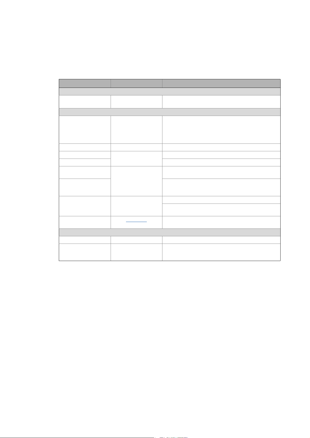
The Lenze Controllers have different interfaces for fieldbus communication:
Area Cabinet Controller Panel Controller
c300 3221 C 3231 C 3241 C p300 p500
Interfaces (on board)
Ethernet1212
EtherCAT 1
CANopen 1
Optional interfaces (communication cards)
CANopen
MC-CAN2
PROFIBUS master
MC-PBM
PROFIBUS slave
MC-PBS
PROFINET device
MC-PND
1)
2)
- -
- -
- -
- -
11
-1
1)
2)
1
-
1) In preparation
2) Only the CAN master functionality is supported.
The Ethernet interface serves to connect the Engineering PC or to create line topologies (no
integrated switch for Controller c300/p300).
More information on the bus systems and configuration can be found in the
communication manuals:
• Controller-based Automation EtherCAT®
• Controller-based Automation CANopen®
• Controller-based Automation PROFIBUS®
• Controller-based Automation PROFINET®
17 Lenze · Controller | Parameter setting & programming · Reference Manual · DMS 1.5 EN · 04/2014 · TD17
Page 18
4 System structure
_ _ _ _ _ _ _ _ _ _ _ _ _ _ _ _ _ _ _ _ _ _ _ _ _ _ _ _ _ _ _ _ _ _ _ _ _ _ _ _ _ _ _ _ _ _ _ _ _ _ _ _ _ _ _ _ _ _ _ _ _ _ _ _
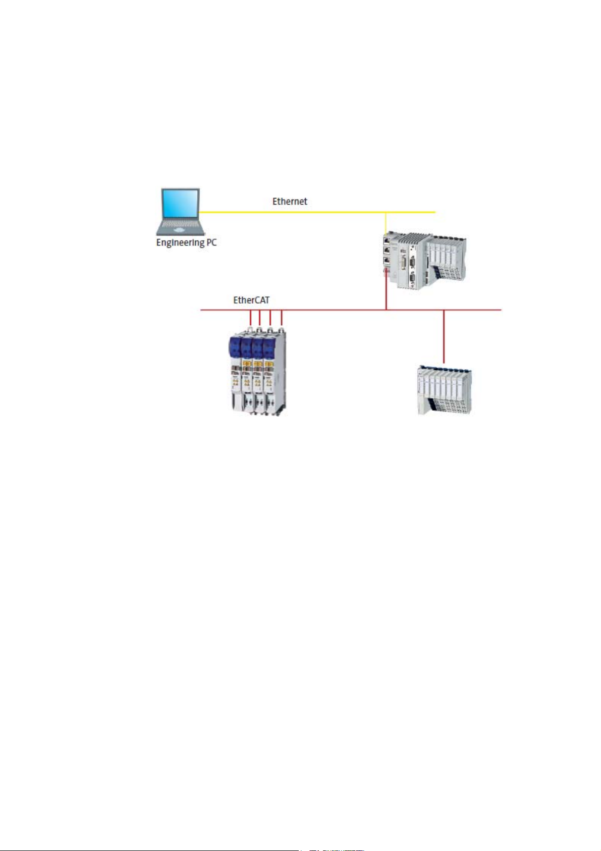
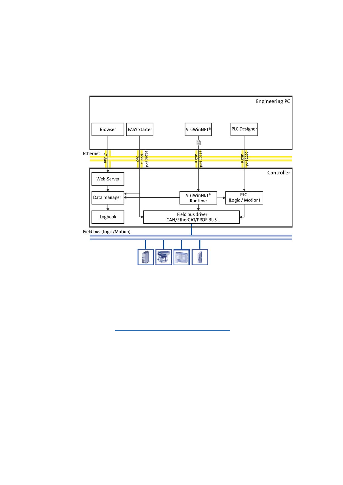
4 System structure
This chapter provides you with an overview of the basic system structure of the Lenze "Controllerbased Automation" system. The system consists of an Engineering PC, a Controller and the devices
communicating with the Controller via the fieldbus.
[4-1] * The PROFIBUS fieldbus driver can only be accessed via PLC (Logic/Motion). Access via EASY Starter and VisiWinNET®
Runtime is not provided.
Controllers and field devices form the automation system to be commissioned via the Engineering
PC. The Engineering PC is a PC/Laptop with Windows® operating system and network connection.
The Engineering PC comes installed with the Lenze Engineering tools
configuration, programming and diagnostics.
The Controller with the PLC (Logic/Motion) is the central control section, consisting of the PLC
runtime program (Runtime software of the Lenze Controllers
application.
Device-internally, the Controller comes with a data manager for configuring and managing the data
of the automation system. The data manager and the fieldbus driver enable the PLC (Logic/Motion)
to access the system components and the field devices.
The fieldbus (Logic/Motion) enables the Controller to read and write the parameters of the
connected field devices.
( 20) for parameter setting,
( 24)) with the running PLC
Lenze · Controller | Parameter setting & programming · Reference Manual · DMS 1.5 EN · 04/2014 · TD17 18
Page 19

4 System structure
_ _ _ _ _ _ _ _ _ _ _ _ _ _ _ _ _ _ _ _ _ _ _ _ _ _ _ _ _ _ _ _ _ _ _ _ _ _ _ _ _ _ _ _ _ _ _ _ _ _ _ _ _ _ _ _ _ _ _ _ _ _ _ _
Note!
There is no OPC server available for PROFIBUS and PROFINET.
Controller c300/p300:
• The »EASY Starter« cannot
• The OPC communication for »VisiWinNET« is exclusively available for Controller p300
without
• Otherwise, only the Lenze "Logic&Motion" direct driver can be used for the data
exchange between »VisiWinNET« and PLC.
PLC.
be used for these devices (in preparation).
19 Lenze · Controller | Parameter setting & programming · Reference Manual · DMS 1.5 EN · 04/2014 · TD17
Page 20
4 System structure
4.1 Engineering tools
_ _ _ _ _ _ _ _ _ _ _ _ _ _ _ _ _ _ _ _ _ _ _ _ _ _ _ _ _ _ _ _ _ _ _ _ _ _ _ _ _ _ _ _ _ _ _ _ _ _ _ _ _ _ _ _ _ _ _ _ _ _ _ _
4.1 Engineering tools
The Engineering PC is a PC/Laptop with Windows® operating system and network connection.
The Engineering PC comes installed with the Lenze Engineering tools which enable the desired
automation solution to be ...
• parameterised/configured;
•programmed;
•diagnosed.
Lenze · Controller | Parameter setting & programming · Reference Manual · DMS 1.5 EN · 04/2014 · TD17 20
Page 21
4 System structure
4.1 Engineering tools
_ _ _ _ _ _ _ _ _ _ _ _ _ _ _ _ _ _ _ _ _ _ _ _ _ _ _ _ _ _ _ _ _ _ _ _ _ _ _ _ _ _ _ _ _ _ _ _ _ _ _ _ _ _ _ _ _ _ _ _ _ _ _ _
»EASY Navigator«: Starting the suitable Engineering tool
The Lenze Engineering software consists of the Engineering tools optimised for the respective
Engineering phase.
The »EASY Navigator« shows the Lenze Engineering tools installed on the Engineering PC. Start the
desired Engineering tool via the corresponding button:
The »EASY Navigator« ...
• simplifies the selection of the Engineering tool, depending on the Engineering phase.
• simplifies starting the desired Engineering tool (depending on the application case).
• makes it possible to select the Engineering tool suitable for the Engineering phase.
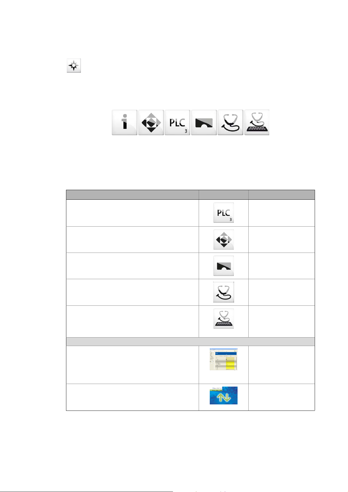
The overview displays the respective function of the Engineering tools:
What would you like to do? Button Engineering tool
Programming
• Program the controller
• Parameterise/commission the Servo-Inverter i700
• Parameterise the I/O system 1000
Parameterising/configuring the inverter
• Parameterise and configure the automation/drive
system
• Parameterise Inverter Drives 8400/Servo Drives 9400
Visualization
• Visualise the applications of the automation system
• Create the visualisation/user interface
Online diagnostics
• Easy online diagnostics of the Controllers (from»EASY
Starter« V1.2) and other Lenze devices
Online parameterisation
• Online parameterisation/commissioning of Lenze
devices
• Direct online parameterisation with an active online
connection to the Lenze devices
Engineering tools that are not included in the »EASY Navigator«:
Controller parameterisation/diagnostics
• »WebConfig« can be used on the controller without
commissioning (integrated web server).
• By the use of »WebConfig«, the parameters of the
controller can be accessed via web browser.
• »WebConfig« can also be started in the »PLC Designer«.
Backup of controller data
•Create data backups
• Restore data after device replacement
• Carry out software update of the Controller
»PLC Designer«
»EASY Starter«
»VisiWinNET«
»EASY Starter«
(Reading parameters)
»EASY Starter«
(Reading/writing
parameters)
»WebConfig«
»Backup & Restore«
1)
1)
21
1) For Controllers c300/p300 in preparation
Lenze · Controller | Parameter setting & programming · Reference Manual · DMS 1.5 EN · 04/2014 · TD17
Page 22

4 System structure
4.2 Controller: The control centre of the Controller-based Automation
_ _ _ _ _ _ _ _ _ _ _ _ _ _ _ _ _ _ _ _ _ _ _ _ _ _ _ _ _ _ _ _ _ _ _ _ _ _ _ _ _ _ _ _ _ _ _ _ _ _ _ _ _ _ _ _ _ _ _ _ _ _ _ _
4.2 Controller: The control centre of the Controller-based Automation
Cabinet controllers: Compact control cabinet design
Cabinet controllers are designed for the demanding continuous use in industrial applications.
Compared to panel controllers, they are not equipped with an integrated display. The Controllers
3231 C and 3241 C are provided with a DVI interface for the connection of an external monitor
panel.
Mounting is carried out in a control cabinet or a corresponding built-in housing on a standard DIN
rail (35 mm). The device-internal backplane bus provides for a direct connection of the I/O system
1000.
Panel controllers: controlling and visualising
Panel controllers are designed for the installation into control cabinets, machine panels, or other
mounting cutouts. They are equipped with rear bolts and clamping screws which provide for easy
mounting and reliable sealing (front panel enclosure IP65/rear panel IP20) in rough industrial
environments. They can be operated easily by directly touching the screen.
General features
• Controller programming, configuration and diagnostics using the »PLC Designer« (on the basis
of CoDeSys 3.x)
• USB 2.0 interfaces and SD card slot, e.g. for data backup/restore
»Backup & Restore« (data backup/restore)
• 4 LEDs for diagnostic purposes:
• Current supply
• Status of the PLC
• Status of the backplane bus
• Freely programmable LED
( 67)
Operating instructions for the Controller
Here, further information on the device-specific properties can be found.
Lenze · Controller | Parameter setting & programming · Reference Manual · DMS 1.5 EN · 04/2014 · TD17 22
Page 23

4 System structure
4.2 Controller: The control centre of the Controller-based Automation
_ _ _ _ _ _ _ _ _ _ _ _ _ _ _ _ _ _ _ _ _ _ _ _ _ _ _ _ _ _ _ _ _ _ _ _ _ _ _ _ _ _ _ _ _ _ _ _ _ _ _ _ _ _ _ _ _ _ _ _ _ _ _ _
Fieldbus communication
The Lenze Controllers have different interfaces for fieldbus communication:
Area Cabinet Controller Panel Controller
c300 3221 C 3231 C 3241 C p300 p500
Interfaces (on board)
Ethernet1212
EtherCAT 1
CANopen 1
Optional interfaces (communication cards)
CANopen
MC-CAN2
PROFIBUS master
MC-PBM
PROFIBUS slave
MC-PBS
PROFINET device
MC-PND
1)
2)
- -
- -
- -
- -
11
-1
1)
2)
1
-
1) In preparation
2) Only the CAN master functionality is supported.
The Ethernet interface serves to connect the Engineering PC or to create line topologies (no
integrated switch for Controller c300/p300).
More information on the bus systems and configuration can be found in the
communication manuals:
• Controller-based Automation EtherCAT®
• Controller-based Automation CANopen®
• Controller-based Automation PROFIBUS®
• Controller-based Automation PROFINET®
23
Lenze · Controller | Parameter setting & programming · Reference Manual · DMS 1.5 EN · 04/2014 · TD17
Page 24
4 System structure
4.3 Runtime software of the Lenze Controllers
_ _ _ _ _ _ _ _ _ _ _ _ _ _ _ _ _ _ _ _ _ _ _ _ _ _ _ _ _ _ _ _ _ _ _ _ _ _ _ _ _ _ _ _ _ _ _ _ _ _ _ _ _ _ _ _ _ _ _ _ _ _ _ _
4.3 Runtime software of the Lenze Controllers
By default, the runtime software is installed in the Lenze Controller as "Logic" mode for the central
control of PLC applications.
Optionally, the "Motion" mode is available, additionally enabling extensive motion control of
Motion functions. The inverter then only acts as an actuating drive.
In addition, the "Visu" mode is available, enabling a central visualisation with the Controller.
The runtime software consists of:
• Operating system (Windows® CE)
• Software components (Logic/Motion), which for instance execute the control program.
• Optional visualisation software (»VisiWinNET« Compact CE).
Differences between "Logic" and "Motion"
Logic Motion
The controller controls...
• simple motion sequences;
• by logically
Logic applications are suitable for the control of inverters
without
• execute simple motion sequences;
• can only be controlled via PLC functionality.
combined control signals.
a Motion functionality which ...
Note!
Depending on the runtime software (Logic/Motion) used, a bus system for a Lenze
device series can only be used in a limited way.
Details can be found in the communication manuals:
• Controller-based Automation EtherCAT®
• Controller-based Automation CANopen®
• Controller-based Automation PROFIBUS®
• Controller-based Automation PROFINET®
The controller controls extensive motion sequences.
The runtime software "Motion" ...
• contains the PLCopen library;
• contains the "Logic" mode;
• supports "SoftMotion".
Motion applications are suitable...
• for the control of inverters executing complex motion
sequences of multi-axes in several dimensions;
• ...for the control of devices that are to traverse
synchronously;
• for the transfer of setpoints.
Lenze · Controller | Parameter setting & programming · Reference Manual · DMS 1.5 EN · 04/2014 · TD17 24
Page 25
4 System structure
4.3 Runtime software of the Lenze Controllers
_ _ _ _ _ _ _ _ _ _ _ _ _ _ _ _ _ _ _ _ _ _ _ _ _ _ _ _ _ _ _ _ _ _ _ _ _ _ _ _ _ _ _ _ _ _ _ _ _ _ _ _ _ _ _ _ _ _ _ _ _ _ _ _
4.3.1 "Logic" runtime software
"Logic" refers to the use of logically combined control signals without Motion functions. When the
"Logic" mode is used, the controller solely controls the motion sequences via logically combined
control signals.
Functionality
• Programming PLC functionality according to IEC 61131-3.
• SoftPLC functionality for executing PLC programs.
• The multi-tasking Windows® CE operating system processes the PLC
programs cyclically.
Performance
The "Logic" mode defines the program function. The performance of the entire
automation system results from the interaction of the runtime software and
the target system in each case. The system performance thus depends on the
processor of the respective controller, and on other factors.
Engineering tool required: »PLC Designer«
4.3.2 "Motion" runtime software
The "Motion" mode makes it possible to execute more complex motion sequences than with the
Logic mode.
In the case of a Motion system, the whole motion control (Motion) of the axes to be controlled takes
place in the controller. The higher-level controller generates the motion profiles for all Motion axes
and transfers the data to the axes via EtherCAT.
A Motion-application...
• ...makes special demands on the cycle time and real-time capability of the bus system between
the controller and the connected field devices.
• for instance is to be used if the axes to be controlled are to be traversed in a synchronised
manner or position setpoints are to be transmitted.
Functionality
• Motion functions according to PLCopen "Function blocks for Motion
• Contains the "Logic" runtime software for the use of logically combined
Additional functions
• Motion function blocks/libraries
• Supports programs for the control of complex motion sequences with
Engineering tool required: »PLC Designer«
Control" version 2.0
control signals.
several axes.
25
Lenze · Controller | Parameter setting & programming · Reference Manual · DMS 1.5 EN · 04/2014 · TD17
Page 26

4 System structure
4.3 Runtime software of the Lenze Controllers
_ _ _ _ _ _ _ _ _ _ _ _ _ _ _ _ _ _ _ _ _ _ _ _ _ _ _ _ _ _ _ _ _ _ _ _ _ _ _ _ _ _ _ _ _ _ _ _ _ _ _ _ _ _ _ _ _ _ _ _ _ _ _ _
4.3.3 "Visu" runtime software
The "Controller-based Automation" system enables the central visualisation of the automation
system.
The visualisation can either run on a separate Controller or monitor panel or on the Controller on
which the "Logic" or "Motion" runtime software is running.
Various options described in the following sections are available for the communication link.
Functionality
The "Visu" mode ...
• extends the Controller to a visualisation device;
• can be used separately or in addition to "Logic" or "Motion".
Engineering tool required: »VisiWinNET«
Note!
There is no OPC server available for PROFIBUS and PROFINET.
Controller c300/p300:
• The OPC communication for »VisiWinNET« is exclusively available for Controller p300
without
• Otherwise, only the Lenze "Logic&Motion" direct driver can be used for the data
exchange between »VisiWinNET« and PLC.
PLC.
Lenze · Controller | Parameter setting & programming · Reference Manual · DMS 1.5 EN · 04/2014 · TD17 26
Page 27
4 System structure
4.3 Runtime software of the Lenze Controllers
_ _ _ _ _ _ _ _ _ _ _ _ _ _ _ _ _ _ _ _ _ _ _ _ _ _ _ _ _ _ _ _ _ _ _ _ _ _ _ _ _ _ _ _ _ _ _ _ _ _ _ _ _ _ _ _ _ _ _ _ _ _ _ _
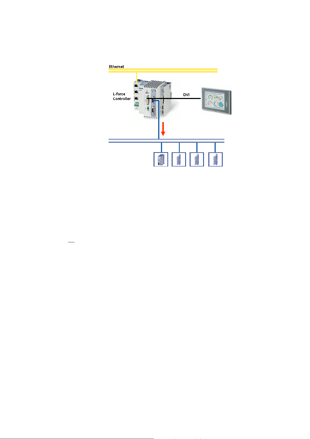
4.3.3.1 Sample topology 1: External monitor panel/display for cabinet controllers
[4-2] Sample topology: Controller 3231 C with an external monitor panel (connected to the DVI interface)
This topology with regard to its performance corresponds to the implemented solution (control/
visualisation on the same controller). The external monitor panel/display shows the visualisation.
Advantages
• Small amount of cabling
• Protected operating conditions
• Extensible topology
•No
impact on the real-time capability of the fieldbus by the visualisation
27
Lenze · Controller | Parameter setting & programming · Reference Manual · DMS 1.5 EN · 04/2014 · TD17
Page 28
4 System structure
4.3 Runtime software of the Lenze Controllers
_ _ _ _ _ _ _ _ _ _ _ _ _ _ _ _ _ _ _ _ _ _ _ _ _ _ _ _ _ _ _ _ _ _ _ _ _ _ _ _ _ _ _ _ _ _ _ _ _ _ _ _ _ _ _ _ _ _ _ _ _ _ _ _
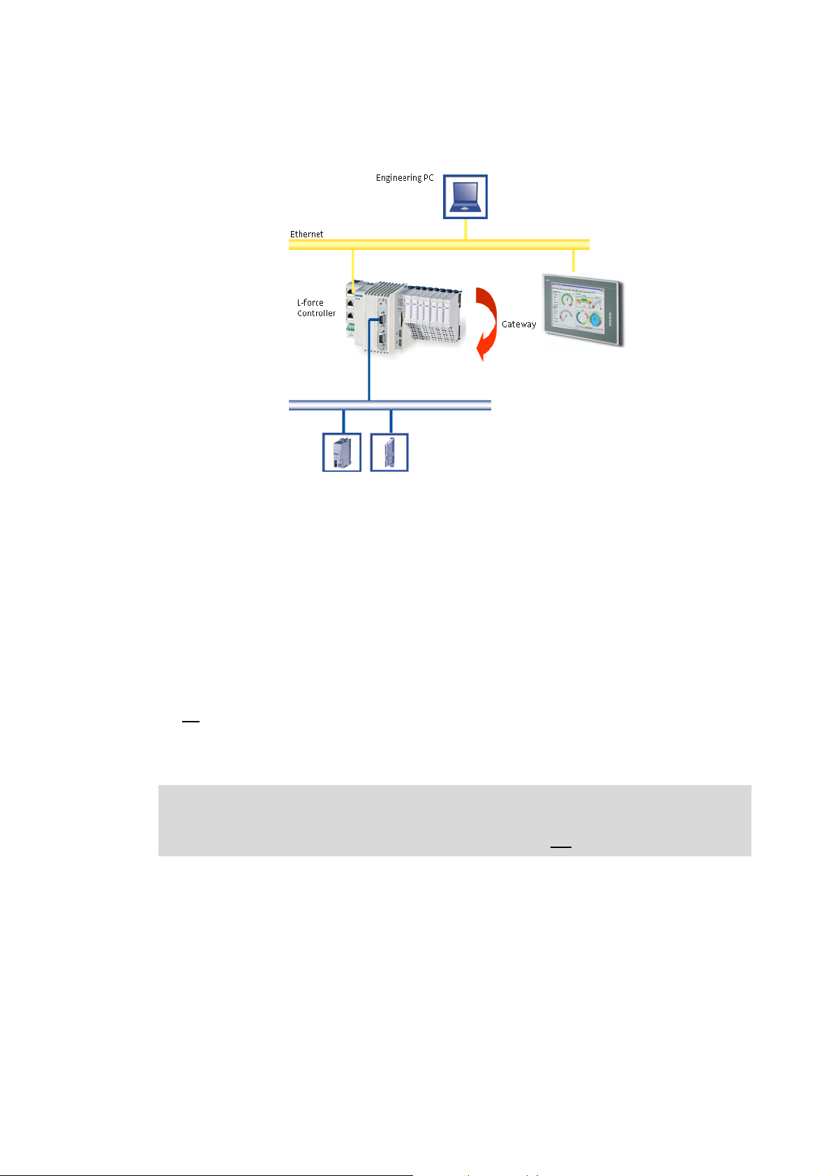
4.3.3.2 Sample topology 2: Separate control and visualisation
[4-3] Sample topology: Controller 3200 C as gateway for the Visualisation Controller (IPC)
The Visualisation Controller (IPC) accesses the field devices via the Controller 3200 C as gateway.
In order to separate the control and visualisation, the integrated gateway function of the controller
can be used.
The use of this topology is advisable...
• to achieve a higher performance;
• for the use of different operating systems within one automation system.
Engineering tools required: »EASY Starter«, »Engineer«
Advantages
•No
impact on the real-time capability of the fieldbus by the visualisation.
• Several visualisations can access the controller.
• Most suitable for extensive visualisation processes.
Note!
In case of Controller c300/p300, the gateway function is not supported (in preparation).
Lenze · Controller | Parameter setting & programming · Reference Manual · DMS 1.5 EN · 04/2014 · TD17 28
Page 29
4 System structure
4.3 Runtime software of the Lenze Controllers
_ _ _ _ _ _ _ _ _ _ _ _ _ _ _ _ _ _ _ _ _ _ _ _ _ _ _ _ _ _ _ _ _ _ _ _ _ _ _ _ _ _ _ _ _ _ _ _ _ _ _ _ _ _ _ _ _ _ _ _ _ _ _ _
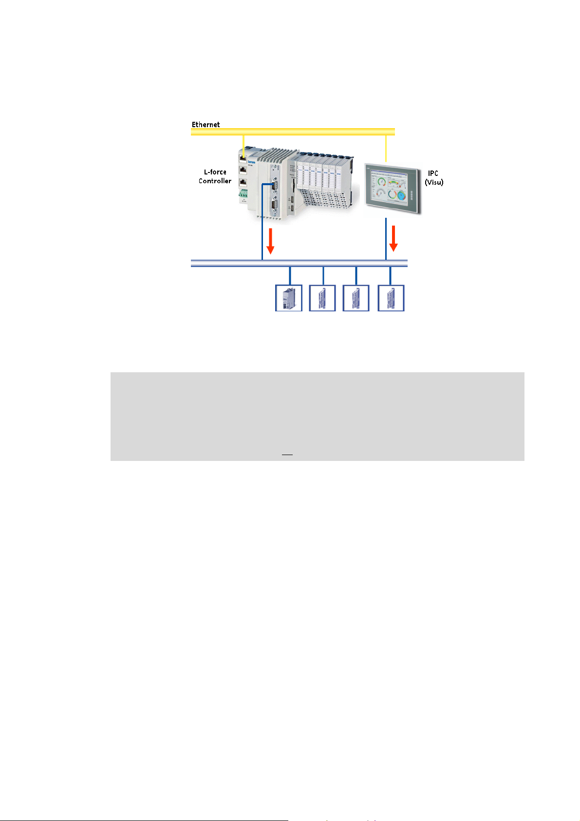
4.3.3.3 Sample topology 3: Independent control and visualisation (CANopen)
[4-4] Sample configuration: Parallel access of Controller 3200 C and Visualisation Controller (IPC)
If this topology is used, the Controller 3200 C and the Visualisation Controller (IPC) access the
fieldbus independently of each other.
Note!
Advantages
Disadvantage
The configuration with a control and configuration independent of each other is only
available for the CANopen bus system!
• CANopen enables (several) fieldbus master independent of each other.
• In connection with EtherCAT, no
• Spatially separate control and visualisation.
• The visualisation has access to the parameters of the field devices.
• The visualisation may disrupt the real-time capability of the fieldbus. This topology therefore is
only suitable for Motion systems to a limited extent (depending on the bus system used).
configuration with two fieldbus masters is possible.
29
Lenze · Controller | Parameter setting & programming · Reference Manual · DMS 1.5 EN · 04/2014 · TD17
Page 30

5 Commissioning the controller
_ _ _ _ _ _ _ _ _ _ _ _ _ _ _ _ _ _ _ _ _ _ _ _ _ _ _ _ _ _ _ _ _ _ _ _ _ _ _ _ _ _ _ _ _ _ _ _ _ _ _ _ _ _ _ _ _ _ _ _ _ _ _ _
5 Commissioning the controller
This chapter provides some general information on the commissioning of a controller. Depending
on the actual hardware installed, different settings are required for integrating the controller into a
network.
Note!
Please observe the predefined IP address of the controller for the initial commissioning:
192.168.5.99 (Lenze setting).
Further information on how to set the IP address of the Controller can be found here:
Entering the IP address of the controller
( 33)
Read the mounting instructions supplied before you start working!
The mounting instructions contains safety instructions which must be observed!
Operating instructions for the Controller
Here, further information on the device-specific properties can be found.
Lenze · Controller | Parameter setting & programming · Reference Manual · DMS 1.5 EN · 04/2014 · TD17 30
Page 31

5 Commissioning the controller
5.1 Identification
_ _ _ _ _ _ _ _ _ _ _ _ _ _ _ _ _ _ _ _ _ _ _ _ _ _ _ _ _ _ _ _ _ _ _ _ _ _ _ _ _ _ _ _ _ _ _ _ _ _ _ _ _ _ _ _ _ _ _ _ _ _ _ _
5.1 Identification
Note!
Here the documentation provides some general information about the commissioning
of a controller. Depending on the design and version of the controller, the
commissioning process can be different.
Every controller is provided with a nameplate containing the device data. The device data are
helpful for identifying the technical equipment of the controller. Detailed information relating to
the nameplate data can be found in the operating instructions for the Controller.
Web-based diagnostics/parameter setting
Via »WebConfig« the configuration of the controller can be identified. The parameter values of the
controller can be represented using the web browser.
Online connection from the Engineering PC to the controller
( 46)
Assigning a unique name to the controller
In order to be able to clearly identify a Controller, the desired name has to be assigned for parameter
13 System identification: Name C0013
Engineering tool (e.g. »PLC Designer«), in order to be able to identify the controller.
5.2 Control elements of the controllers
Depending on the equipment and type, the different device series are provided with various control
elements (e.g. function keys for external monitor panels) and status LEDs for diagnostic purposes.
Status LEDs of the Controllers
The controllers can be operated via external input devices (keyboard/mouse). This makes it possible
to carry out comprehensive diagnostics and configuration tasks directly on the controller.
Operating instructions for the Controller
Here, further information on the device-specific properties of the Controller can be
found.
. The name assigned can then be used in the corresponding
( 80)
31
Lenze · Controller | Parameter setting & programming · Reference Manual · DMS 1.5 EN · 04/2014 · TD17
Page 32

5 Commissioning the controller
5.3 Starting the controller
_ _ _ _ _ _ _ _ _ _ _ _ _ _ _ _ _ _ _ _ _ _ _ _ _ _ _ _ _ _ _ _ _ _ _ _ _ _ _ _ _ _ _ _ _ _ _ _ _ _ _ _ _ _ _ _ _ _ _ _ _ _ _ _
5.3 Starting the controller
Note!
During the starting process of the controller
If a non
stopped!
When the controller is running
Removal of the SD card will lead to a system failure!
-bootable USB flash drive is connected during the starting sequence, it will be
• Remove the USB stick and restart the Controller.
• Alternatively, the USB stick can be prepared using the »Backup & Restore« software.
Further information can be found in the online help of the »Backup & Restore«
software.
• The SD card must not be removed while the controller is running (no "Hot Plugging"
of the SD card possible).
• The SD card is required for the system start since it contains the system files for the
starting process.
The SD card and the internal flash memory are the storage media of the controller. Depending on
the device, the SD card can be used optionally. Detailed information can be found in the devicespecific operating instructions.
The controller saves the user data (like projects and individual data) on the SD card. The operating
system and the Lenze software are saved in the internal flash memory.
Note!
The standard-IP address of the controller is 192.168.5.99 (Lenze setting)
The preset IP configuration can be changed in the »WebConfig«.
Setting IP addresses on the Engineering PC (example: Windows® XP)
Entering the IP address of the controller ( 33)
After 15 seconds, the network configuration dialog box will close automatically; the
controller continues with the starting process.
Error case: Controller c300/p300 does not start
In case the Controller c300 or p300 does not start, the Lenze standard settings can be activated
using the reset pushbutton.
How to activate the Lenze standard settings:
1. Switch off voltage supply.
( 46)
2. Press reset pushbutton.
3. While pressing the reset pushbutton, switch on the voltage supply and keep the reset
pushbutton pressed for at least 10 s.
• If the error LED is blinking (green/red) after this action, a manual mains switching is
required.
• The Controller has to be disconnected from the mains until all LEDs go off.
Lenze · Controller | Parameter setting & programming · Reference Manual · DMS 1.5 EN · 04/2014 · TD17 32
Page 33

5 Commissioning the controller
5.4 Configuring the controller
_ _ _ _ _ _ _ _ _ _ _ _ _ _ _ _ _ _ _ _ _ _ _ _ _ _ _ _ _ _ _ _ _ _ _ _ _ _ _ _ _ _ _ _ _ _ _ _ _ _ _ _ _ _ _ _ _ _ _ _ _ _ _ _
5.4 Configuring the controller
This chapter provides information on how to configure the Controller during initial commissioning.
The IP address setting is preserved after a restart of the system.
5.4.1 Establishing an automatic dial-up connection
Further information on how to establish an automatic dial-up connection, remote maintenance and
diagnostics options can be found under:
Remote maintenance and diagnostics
In order to carry out a remote maintenance on the controller different mechanisms are provided:
( 79)
Diagnostics via Telnet
Data transfer via FTP ( 85)
Activate Windows® CE interface ( 92)
Diagnostics with the logbook ( 89)
( 82)
Note!
Controller c300/p300:
• These devices come with a deactivated Telnet and FTP in the Lenze standard setting.
• The functions can be activated via the »WebConfig«. The activation of the functions
5.4.2 Entering the IP address of the controller
The controller has the following network settings by default:
Address Lenze setting
IP address 192.168.5.99
Subnetwork 255.255.255.0
Default gateway 192.168.5.1
can influence the real-time behaviour.
• After a restart of the Controller, the functions are deactivated again.
33
During initial commissioning of the Controller, the desired IP address has to be entered.
Optionally, the network settings can be selected via a file:
Specifying the IP address of the controller via file (optional)
Lenze · Controller | Parameter setting & programming · Reference Manual · DMS 1.5 EN · 04/2014 · TD17
( 36)
Page 34

5 Commissioning the controller
5.4 Configuring the controller
_ _ _ _ _ _ _ _ _ _ _ _ _ _ _ _ _ _ _ _ _ _ _ _ _ _ _ _ _ _ _ _ _ _ _ _ _ _ _ _ _ _ _ _ _ _ _ _ _ _ _ _ _ _ _ _ _ _ _ _ _ _ _ _
5.4.2.1 Cabinet controllers with external monitor panels (3231 C/3241 C)
Note!
If an external display (monitor panel) is used, the switch-on sequence of display/
controller must be observed so that it can be correctly controlled by the controller:
• Connect the external display to the DVI output of the controller and switch it on
before
switching on the controller.
After connection of a monitor panel/an external display to a running controller, the
display resolution is VGA .
• Calibrate the monitor panel/ display connected, so that the screen content can be
displayed correctly.
Tip!
Connect a keyboard to the Controller to be able to enter the IP address.
Then you can make the entries:
[5-1] IP settings of the controller by default
• Start the control panel with <Shift+F4>.
• Start the network connections by double-click and enter the IP address, subnet mask, and the
default gateway.
• After clicking the button the IP address is saved and need not be entered again when the
system is restarted.
Lenze · Controller | Parameter setting & programming · Reference Manual · DMS 1.5 EN · 04/2014 · TD17 34
Page 35

5 Commissioning the controller
5.4 Configuring the controller
_ _ _ _ _ _ _ _ _ _ _ _ _ _ _ _ _ _ _ _ _ _ _ _ _ _ _ _ _ _ _ _ _ _ _ _ _ _ _ _ _ _ _ _ _ _ _ _ _ _ _ _ _ _ _ _ _ _ _ _ _ _ _ _
5.4.2.2 Cabinet Controller without external monitor panel (c300/3221 C)
To configure a Cabinet Controller without a connected monitor panel (e.g. Controller 3221 C), a PC/
laptop with the suitable addresses (IP address, subnet mask, default gateway) is required.
• Connect the PC/laptop to the controller by means of a "crossed" network cable.
• Change the settings on an HTML compliant browser:
Setting IP addresses on the Engineering PC (example: Windows® XP)
• Connection establishment: enter the IP address of the controller in the browser: 192.168.5.99
(Lenze default setting).
• In »WebConfig«, click the Ethernet button.
• Enter the desired IP address, subnet mask and default gangway of the Controller.
•Click Accept & Save all.
•Set Use IP configuration to the value "Activate device".
• Click again Accept & Save all in order to save the network settings permanently.
( 46)
35
Lenze · Controller | Parameter setting & programming · Reference Manual · DMS 1.5 EN · 04/2014 · TD17
Page 36

5 Commissioning the controller
5.4 Configuring the controller
_ _ _ _ _ _ _ _ _ _ _ _ _ _ _ _ _ _ _ _ _ _ _ _ _ _ _ _ _ _ _ _ _ _ _ _ _ _ _ _ _ _ _ _ _ _ _ _ _ _ _ _ _ _ _ _ _ _ _ _ _ _ _ _
5.4.3 Specifying the IP address of the controller via file (optional)
How to proceed:
1. Create file "ip.txt" on the Engineering PC.
2. Save file "ip.txt" to the SD card of the controller by connecting the SD card to the
Engineering PC using a memory card reader.
File "ip.txt"
172.31.207.88 {IP address}
255.255.255.0 {subnet mask}
172.31.201.1 {gateway}
[5-2] Example of an "ip.txt" file for selecting the IP address
In ASCII file "ip.txt" an IP address is defined which can be selected for the controller.
• Copy file "ip.txt" to the root directory of the SD card.
• Insert the SD card into the controller. Then start the controller.
Starting the controller
• When the system is started ...
• the controller reads in the IP address file "ip.txt" from the SD card;
• the controller writes the result (Result) to the ip.txt file:
( 32)
172.31.207.88
255.255.255.0
172.31.201.1
Result: 2010-9-24 14:42:23 :Success: IP Settings taken from file.
[5-3] Example of an "ip.txt" file for IP address selection with result entry
• Then, the Controller renames the file: "ip_old.txt".
• To select the IP address once again using the file, the file must be renamed to "ip.txt".
Tip!
The "ip.txt" file can be used to select the use of the DHCP. For this, write "DHCP" into the
first line of the file. Then, the following lines will no longer be considered.
Lenze · Controller | Parameter setting & programming · Reference Manual · DMS 1.5 EN · 04/2014 · TD17 36
Page 37

5 Commissioning the controller
5.4 Configuring the controller
_ _ _ _ _ _ _ _ _ _ _ _ _ _ _ _ _ _ _ _ _ _ _ _ _ _ _ _ _ _ _ _ _ _ _ _ _ _ _ _ _ _ _ _ _ _ _ _ _ _ _ _ _ _ _ _ _ _ _ _ _ _ _ _
5.4.4 Establishing Windows® CE access rights
In order to be able to establish a connection to the controller, each user has to be assigned access
rights. For this the respective user has to be set up as a Windows® CE user with a user name and a
password. Windows® CE users can be set up via »WebConfig« and the »EASY Starter«:
Setting up Windows® CE users in »WebConfig«
The representation for user 1 is displayed. The users 2 to 10 are displayed analogously.
5.4.4.1 Setting up Windows® CE users in »WebConfig«
( 37)
Note!
You have to be set up as Windows® CE user to have authorisations for further services
like FTP, telnet, or web server access.
• Up to ten Windows® CE users can be set up in »WebConfig« the User management 10 area.
• Use parameters 101 to 169 to set up the user name, password, and various authorisations for a
maximum of ten users.
The representation for user 1 is displayed. The users 2 to 10 are displayed analogously.
Detailed information on the parameters can be found here:
Basic parameters of the Controllers 3200 C/c300 and p300/p500
( 131)
37
Lenze · Controller | Parameter setting & programming · Reference Manual · DMS 1.5 EN · 04/2014 · TD17
Page 38

5 Commissioning the controller
5.4 Configuring the controller
_ _ _ _ _ _ _ _ _ _ _ _ _ _ _ _ _ _ _ _ _ _ _ _ _ _ _ _ _ _ _ _ _ _ _ _ _ _ _ _ _ _ _ _ _ _ _ _ _ _ _ _ _ _ _ _ _ _ _ _ _ _ _ _
5.4.5 Using your own wallpaper on the controller (Windows® CE)
The standard wallpaper of the controller can be replaced by your own wallpaper.
The wallpaper must meet the following conditions:
• File format: bitmap (*.bmp)
• The resolution of the image must correspond to the resolution of the monitor panel to achieve
a correct representation:
Screen sizes Panel Controller
p300 p500
Diagonal
measurement
Resolution [pixel] 480 x 272
10.9 cm
(4.3")
(PSP)
17.8 cm
(7.0")
800 x 480
(WVGA)
26.4 cm
(10.4")
800 x 600
(SVGA)
17.8 cm
(7.0")
800 x 480
(WVGA)
26.4 cm
(10.4")
800 x 600
(SVGA)
38.1 cm
(15.0")
1024 x 768
(XGA)
How to proceed:
Copy the desired bitmap file to the SD card of the controller, directory: \CustomBitmap.
Directory name on the controller if the SD card has been inserted into the controller:
\USBStorage\CustomBitmap)
Lenze · Controller | Parameter setting & programming · Reference Manual · DMS 1.5 EN · 04/2014 · TD17 38
Page 39

5 Commissioning the controller
5.5 I/O system 1000 at the backplane bus of a cabinet controller
_ _ _ _ _ _ _ _ _ _ _ _ _ _ _ _ _ _ _ _ _ _ _ _ _ _ _ _ _ _ _ _ _ _ _ _ _ _ _ _ _ _ _ _ _ _ _ _ _ _ _ _ _ _ _ _ _ _ _ _ _ _ _ _
5.5 I/O system 1000 at the backplane bus of a cabinet controller
The Cabinet Controllers 3200 C and c300 allow for a direct connection of the I/O system 1000 to the
integrated backplane bus.
The modules of the I/O system 100 connected to the backplane bus of the Controller can be
parameterised in the »PLC Designer«.
System manual for I/O system 1000 (EPM-Sxxx)
Here, further information on the parameter setting/configuration can be found.
5.5.1 Configuring I/O modules at the backplane bus
The following illustration is a schematic representation of the controller hardware structure
including I/O modules.
The I/O system 1000 includes the following components:
• I/O module coupler for voltage supply of the I/O compound modules
• I/O compound modules:
Up to 64 modules are possible which are connected to the Controller 3200 C via the Lenze
backplane bus.
In order to be able to access the modules by means of a PLC program (read input signals/write
output signals), the modules have to be configured in the »PLC Designer«. For this, map the physical
arrangement of the I/O modules in the »PLC Designer«.
[5-4] Example: mapping the physical arrangement of modules 1...7 in the »PLC Designer«
39
Lenze · Controller | Parameter setting & programming · Reference Manual · DMS 1.5 EN · 04/2014 · TD17
Page 40

5 Commissioning the controller
5.5 I/O system 1000 at the backplane bus of a cabinet controller
_ _ _ _ _ _ _ _ _ _ _ _ _ _ _ _ _ _ _ _ _ _ _ _ _ _ _ _ _ _ _ _ _ _ _ _ _ _ _ _ _ _ _ _ _ _ _ _ _ _ _ _ _ _ _ _ _ _ _ _ _ _ _ _
How to configure the I/O modules in the »PLC Designer«:
1. Append the I/O modules used as Devices to the I/O module coupler:
Note: The sequence of the I/O modules in the device tree must comply with the physical
arrangement.
2. View in the device tree/Device view:
• If everything is configured correctly, all modules are marked with the symbol in the
device tree after going online and starting the PLC.
• In the event of an error, i.e. if the configuration deviates from the physical arrangement,
the modules are marked with the symbol.
Lenze · Controller | Parameter setting & programming · Reference Manual · DMS 1.5 EN · 04/2014 · TD17 40
Page 41

5 Commissioning the controller
5.5 I/O system 1000 at the backplane bus of a cabinet controller
_ _ _ _ _ _ _ _ _ _ _ _ _ _ _ _ _ _ _ _ _ _ _ _ _ _ _ _ _ _ _ _ _ _ _ _ _ _ _ _ _ _ _ _ _ _ _ _ _ _ _ _ _ _ _ _ _ _ _ _ _ _ _ _
Use the I/O module coupler tab for diagnostics purposes using the PLC application.
Example: Insert the b_myError variable in this tab. The variable is globally declared and the PLC
application is able to evaluate it.
5.5.2 Determining the topology of the I/O modules automatically
In addition to appending devices manually, the »PLC Designer« allows for the automatic recognition
of I/O modules connected (fieldbus scan).
For this purpose, execute the Start Search command in the context menu of the I/O module coupler:
41
Lenze · Controller | Parameter setting & programming · Reference Manual · DMS 1.5 EN · 04/2014 · TD17
Page 42

5 Commissioning the controller
5.6 Tabs of the I/O modules at the backplane bus
_ _ _ _ _ _ _ _ _ _ _ _ _ _ _ _ _ _ _ _ _ _ _ _ _ _ _ _ _ _ _ _ _ _ _ _ _ _ _ _ _ _ _ _ _ _ _ _ _ _ _ _ _ _ _ _ _ _ _ _ _ _ _ _
5.6 Tabs of the I/O modules at the backplane bus
The Workspace ...
• uses various tabs to display the properties and settings of the module selected from the Device
view.
• serves to edit the parameters of the individual I/O compound modules.
Depending on the module selected from the Device view, different tabs are available in the
Workspace.
I/O module coupler (backplane bus)
Tab Contents
Diagnostics Error status of the modules.
Error messages (backplane bus)
I/O module coupler List of all available objects for the parameter setting of the I/O compound
modules - digital I/O.
Status Status information of the module coupler.
Information Project information and catalogue information of the module coupler.
( 43)
Every I/O module at the backplane bus is represented by means of the following tab:
I/O compound modules
Tab Contents
Parameter • Offline configuration of the I/O module
• All parameters of the I/O compound module
• Parameterising digital modules:
Polarity of the control signals, status in the event of an error for digital
output modules.
• Parameterising analog modules:
Signal functions, status in the event of an error.
Depending on the type of I/O module, specific settings are possible.
Further information is provided in the online help of the I/O system 1000.
I/O module image Process image of the I/O module
Status Status information of the I/O compound module.
Information Designation and connection diagram of the I/O compound module.
Lenze · Controller | Parameter setting & programming · Reference Manual · DMS 1.5 EN · 04/2014 · TD17 42
Page 43

5 Commissioning the controller
5.7 Error messages (backplane bus)
_ _ _ _ _ _ _ _ _ _ _ _ _ _ _ _ _ _ _ _ _ _ _ _ _ _ _ _ _ _ _ _ _ _ _ _ _ _ _ _ _ _ _ _ _ _ _ _ _ _ _ _ _ _ _ _ _ _ _ _ _ _ _ _
5.7 Error messages (backplane bus)
Error messages are represented on the Diagnostics tab of the I/O module coupler.
[5-5] Example: Topology error, the EPM-S501 module cannot be reached at the backplane bus.
Error messages
The following error messages can be displayed:
Error number Error text/remedy
11 Too many I/O modules for the task cycle time selected.
• Increase cycle time.
12 FIFO response full.
• Contact Lenze
32 Timeout reset
• Contact Lenze
33 Timeout reset error
96 Too many I/O modules for the task cycle time selected.
97 Too many I/O modules for the task cycle time selected.
98 Too many I/O modules for the task cycle time selected.
99 Too many I/O modules for the task cycle time selected.
100 Too many I/O modules for the task cycle time selected.
101 Timeout for master queue operation
102 Bus initialisation error with one I/O module
103 Master queue operation error
104 Read semaphore timeout for group 1
105 Read semaphore timeout for group 2
106 Read semaphore timeout for group 3
107 Write semaphore timeout for group 1
108 Write semaphore timeout for group 2
109 Write semaphore timeout for group 3
110 Internal error of the backplane bus hardware
116 Read semaphore timeout for group 1
• Contact Lenze
• Increase cycle time.
• Increase cycle time.
• Increase cycle time.
• Increase cycle time.
• Increase cycle time.
• Contact Lenze
• Contact Lenze
• Not all I/O modules can be reached.
• Contact Lenze
43
Lenze · Controller | Parameter setting & programming · Reference Manual · DMS 1.5 EN · 04/2014 · TD17
Page 44

5 Commissioning the controller
5.7 Error messages (backplane bus)
_ _ _ _ _ _ _ _ _ _ _ _ _ _ _ _ _ _ _ _ _ _ _ _ _ _ _ _ _ _ _ _ _ _ _ _ _ _ _ _ _ _ _ _ _ _ _ _ _ _ _ _ _ _ _ _ _ _ _ _ _ _ _ _
Error number Error text/remedy
117 Read semaphore timeout for group 2
118 Read semaphore timeout for group 3
119 Write semaphore timeout for group 1
120 Write semaphore timeout for group 2
121 Write semaphore timeout for group 3
136 Configuration error in the I/O module topology.
137 Too many tasks for the processing of I/O modules. Three tasks at the maximum.
138 Device description does not contain a device type
• Contact Lenze
139 Error while writing the initialisation parameters
• Contact Lenze
140 No definition for number of channels in device description
• Contact Lenze
181 Synchronisation of the I/O system incorrect
• Contact Lenze
200 SDO timeout
• Contact Lenze
220 SDO communication error
• Contact Lenze
221 Physical I/O module topology could not be read.
• Contact Lenze
222 I/O system driver could not be opened.
• Contact Lenze
Lenze · Controller | Parameter setting & programming · Reference Manual · DMS 1.5 EN · 04/2014 · TD17 44
Page 45

6 Parameter setting using »WebConfig«
6.1 System structure
_ _ _ _ _ _ _ _ _ _ _ _ _ _ _ _ _ _ _ _ _ _ _ _ _ _ _ _ _ _ _ _ _ _ _ _ _ _ _ _ _ _ _ _ _ _ _ _ _ _ _ _ _ _ _ _ _ _ _ _ _ _ _ _
6 Parameter setting using »WebConfig«
This chapter contains some information about the web-based parameterisation of the controller via
»WebConfig«.
6.1 System structure
6.2 Parameterising the controller
All settings that can be used for parameterising the controller are included in a numbered
parameter list.
»WebConfig« can be remotely called via http by an external Engineering PC which can be reached
via network. The Engineering PC is a desktop computer with a Windows® (XP/7) operating system.
Basic parameters of the Controllers 3200 C/c300 and p300/p500
( 131)
45
Lenze · Controller | Parameter setting & programming · Reference Manual · DMS 1.5 EN · 04/2014 · TD17
Page 46

6 Parameter setting using »WebConfig«
6.3 Online connection from the Engineering PC to the controller
_ _ _ _ _ _ _ _ _ _ _ _ _ _ _ _ _ _ _ _ _ _ _ _ _ _ _ _ _ _ _ _ _ _ _ _ _ _ _ _ _ _ _ _ _ _ _ _ _ _ _ _ _ _ _ _ _ _ _ _ _ _ _ _
6.3 Online connection from the Engineering PC to the controller
Connect the Engineering PC to the Controller using a network cable or connect the Controller to the
network which is accessed to the Engineering PC.
Note!
In the case of a direct connection between the Engineering PC and the controller, a
crossed network cable is required.
The settings of the static IP address of the Engineering PC are only to be carried out for
the direct connection between the Engineering PC and controller.
6.3.1 Setting IP addresses on the Engineering PC (example: Windows® XP)
Note!
Recommended setting for the Engineering PC:
IP address: <192.168.5.100>
Default settings of the controller:
IP address: <192.168.5.99>, subnetwork <255.255.255.0>.
Setting for the direct connection between Engineering PC and controller:
How to set the static IP address of the Engineering PC:
1. Open the Network connections dialog box.
StartSettingsNetwork connections
2. Select the network interface which is connected to the Controller.
Right-click Properties.
3. Select Internet protocol (TCP/IP).
4. Click the Properties button.
5. Select the Alternate configuration tab.
6. Select the User configured option.
• Enter the IP address. The subnet range of this IP address and the one of the IP address of
the controller must be the same, example: <192.168.5.100> (Lenze setting of the
controller: <192.168.5.99>).
• Enter the subnet mask of the Engineering PC (standard setting: <255.255.255.0>)
7. Close the individual dialog boxes with OK/Close.
Lenze · Controller | Parameter setting & programming · Reference Manual · DMS 1.5 EN · 04/2014 · TD17 46
Page 47

6 Parameter setting using »WebConfig«
6.4 Start »WebConfig«
_ _ _ _ _ _ _ _ _ _ _ _ _ _ _ _ _ _ _ _ _ _ _ _ _ _ _ _ _ _ _ _ _ _ _ _ _ _ _ _ _ _ _ _ _ _ _ _ _ _ _ _ _ _ _ _ _ _ _ _ _ _ _ _
The Properties of internet protocol (TCP/IP) dialog window
How to set the browser:
1. Open the browser at the Engineering PC.
(This setting refers to the Microsoft Internet Explorer.)
2. Select the Proxy settings dialog window:
6.4 Start »WebConfig«
Start a browser at the Engineering PC and enter the IP address of the controller.
(ToolsInternet options ConnectionsSettingsAdvanced)
3. Position the cursor in the Exceptions field at the end of the entries available.
4. Enter the IP address of the controller: <;192.168.5*> (Lenze setting)
5. Close the individual dialog windows with OK.
1. Enter <User name:password>. As default
setting, admin:admin is preselected. Any
user set up on the controller can log in.
User management
2. Confirm with OK .
3. Afterwards, »WebConfig« is visible.
User interface of »WebConfig«
( 55)
( 48)
47
Lenze · Controller | Parameter setting & programming · Reference Manual · DMS 1.5 EN · 04/2014 · TD17
Page 48

6 Parameter setting using »WebConfig«
6.5 User interface of »WebConfig«
_ _ _ _ _ _ _ _ _ _ _ _ _ _ _ _ _ _ _ _ _ _ _ _ _ _ _ _ _ _ _ _ _ _ _ _ _ _ _ _ _ _ _ _ _ _ _ _ _ _ _ _ _ _ _ _ _ _ _ _ _ _ _ _
6.5 User interface of »WebConfig«
The user interface of »WebConfig« is divided into the following areas - :
Note!
The representation of the user interface in area depends on the respective system
configuration!
Lenze · Controller | Parameter setting & programming · Reference Manual · DMS 1.5 EN · 04/2014 · TD17 48
Page 49

6 Parameter setting using »WebConfig«
6.5 User interface of »WebConfig«
_ _ _ _ _ _ _ _ _ _ _ _ _ _ _ _ _ _ _ _ _ _ _ _ _ _ _ _ _ _ _ _ _ _ _ _ _ _ _ _ _ _ _ _ _ _ _ _ _ _ _ _ _ _ _ _ _ _ _ _ _ _ _ _
Area Information
Menu buttons Device parameters of the controller
• Parameter list 1: All parameters of the standard device
• Parameter list 2: All parameters of the installed communication cards
• PLC parameters
• Ethernet (on board) parameters
• EtherCAT parameters
Diagnostic/device commands
• Logbook parameters
• Logbook of the controller
• Device commands
User management
... for settings of the users 1 - 10
General parameters
•Time
•UPS settings
• Monitoring functions
•Memory
•Diagnostics
»Backup & Restore«
... for carrying out a backup, restore or software updates
Detailed information on the parameters of the »Backup & Restore« can be found here:
Backup&Restore
Further information on how to carry out a backup, restore or software updates can be
found in the »Backup & Restore« software manual.
Parameters of the communication cards
( 55)
( 55)
( 174)
( 50)
( 51)
( 56)
Buttons Parameter list buttons ( 57)
Display area Parameter display
Note:
• The represented parameters of slots 1 and 2 depend on the corresponding
communication cards that are installed!
• The additional buttons for the actually installed communication cards are
automatically added to the menu buttons.
• The top-down order of the buttons corresponds to the order in which the
communication cards have been installed (slot 1, slot 2).
Detailed information on the parameters of the communication cards can be found
here:Communication cards: optional interface
Automatic update
Language selection
Depending on the selected menu button, the parameters can be viewed in this area.
• Parameter numbers
• Name of the parameter
• Representation of the display, entry, selection, control and list fields.
( 57)
( 57)
( 178)
Depending on the equipment of the controller, deviating components are shown by use of the
menu control fields.
Detailed information on the parameters of the Controller can be found here:
Basic parameters of the Controllers 3200 C/c300 and p300/p500
( 131)
49
Lenze · Controller | Parameter setting & programming · Reference Manual · DMS 1.5 EN · 04/2014 · TD17
Page 50

6 Parameter setting using »WebConfig«
6.5 User interface of »WebConfig«
_ _ _ _ _ _ _ _ _ _ _ _ _ _ _ _ _ _ _ _ _ _ _ _ _ _ _ _ _ _ _ _ _ _ _ _ _ _ _ _ _ _ _ _ _ _ _ _ _ _ _ _ _ _ _ _ _ _ _ _ _ _ _ _
Representation of parameter values
In the display area of »WebConfig«, settings of device parameters are represented with different
background colours which have the following meaning:
Colour Example Meaning
Pale yellow Parameter (read only)
• Display of status information and actual values.
Yellow Parameter (read and write)
• The current parameter value of the device is displayed. Changes with regard to a
parameter have to be transmitted to the device with Accept or Accept & Save All.
red Entry of a value beyond the valid range
•Via Refresh the original value is shown again.
• A correct value can be entered in the red input field and transmitted to the device
with Accept or Accept & Save All .
In the following the individual menus of the web-based parameterisation »WebConfig« are
described.
6.5.1 Device parameters of the controller
Button Function
Parameter list 1
Parameter list 2
PLC
Ethernet
EtherCAT
Displays all parameters of the standard device of the controller in
numerically ascending order.
This user interface helps you to e.g. ...
• find system properties and version numbers (read-only parameters);
• set the system time;
• Activate the USB connection at the front of the monitor panel.
Basic parameters of the Controllers 3200 C/c300 and p300/p500
The other menu buttons of the areas , and are a filtered view of
parameter list 1.
Displays all parameters of the installed communication cards in numerically
ascending order.
The top-down order of the parameters corresponds to the order in which the
communication cards have been installed (slot 1, slot 2).
Detailed information on the parameters of the communication cards can be
found here:
Parameters of the communication cards
Communication cards: optional interface
The other menu buttons of area are a filtered view of parameter list 2.
Displays the PLC parameters in numerically ascending order.
From this user interface can e.g. be seen:
•The PLC status,
• Information on a PLC project.
Detailed information on the parameters of the PLC can be found here:
PLC (Logic/Motion)
Displays the Ethernet (on board) parameters in numerically ascending order.
On this user interface the network settings of the (on board) network
connection are displayed/set.
Detailed information on the EtherCAT parameters can be found here:
Ethernet (on board)
Displays the EtherCAT parameters (information on EtherCAT master and
EtherCAT slaves).
Detailed information on the EtherCAT parameters can be found here:
EtherCAT
( 131)
( 56)
( 178)
( 172)
( 161)
( 163)
Lenze · Controller | Parameter setting & programming · Reference Manual · DMS 1.5 EN · 04/2014 · TD17 50
Page 51

6 Parameter setting using »WebConfig«
6.5 User interface of »WebConfig«
_ _ _ _ _ _ _ _ _ _ _ _ _ _ _ _ _ _ _ _ _ _ _ _ _ _ _ _ _ _ _ _ _ _ _ _ _ _ _ _ _ _ _ _ _ _ _ _ _ _ _ _ _ _ _ _ _ _ _ _ _ _ _ _
6.5.2 Diagnostic/device commands
Button Function
Diagnostics
Logbook
Device commands
Displays parameters of the following areas:
•Diagnostics
•Logbook
In the Logbook area you can configure settings regarding the Logbook.
Further information on remote maintenance options of the Controller can
be found here:
Remote maintenance and diagnostics
Displays logbook contents.
• Different filter settings display, for instance, only the oldest or only the
most recent logbook entries.
Logbook
Displays the commands of the Controller to be executed.
The available commands can be found in the following section under
18 (C0018
Basic parameters of the Controllers 3200 C/c300 and p300/p500
( 52)
)
( 79)
( 131)
51
Lenze · Controller | Parameter setting & programming · Reference Manual · DMS 1.5 EN · 04/2014 · TD17
Page 52

6 Parameter setting using »WebConfig«
6.5 User interface of »WebConfig«
_ _ _ _ _ _ _ _ _ _ _ _ _ _ _ _ _ _ _ _ _ _ _ _ _ _ _ _ _ _ _ _ _ _ _ _ _ _ _ _ _ _ _ _ _ _ _ _ _ _ _ _ _ _ _ _ _ _ _ _ _ _ _ _
6.5.3 Logbook
This user interface displays the logbook information of the Controller.
The logbook offers various filter options to systematically display specific logbook contents.
Note!
If the ClearLog button is clicked, the entire logbook contents of the controller are deleted
without further query!
6.5.3.1 Structure of a logbook entry: example
Logbook entry, example Meaning
00001 Consecutive number of the entry
2009-03-24 14:45:26 Date (year/month/day) and time (hour/minute/second) on the
Log service Application that has triggered the entry (application)
Logbook deleted Description of the event
Continuous processing Event origin within the application (area)
Warning Severity of the event
Controller when the logbook entry was made
Lenze · Controller | Parameter setting & programming · Reference Manual · DMS 1.5 EN · 04/2014 · TD17 52
Page 53

6 Parameter setting using »WebConfig«
6.5 User interface of »WebConfig«
_ _ _ _ _ _ _ _ _ _ _ _ _ _ _ _ _ _ _ _ _ _ _ _ _ _ _ _ _ _ _ _ _ _ _ _ _ _ _ _ _ _ _ _ _ _ _ _ _ _ _ _ _ _ _ _ _ _ _ _ _ _ _ _
6.5.3.2 Filter options
Section Information
Logbook Display logbook entries
Structure of a logbook entry: example
Time period Select filter for the time period of the logbook entries shown
• The logbook will only display entries which are in the selected time
period.
Application Set filter for the application
• The logbook will only display entries for the selected applications.
Severity Set filter for the severity of the error messages displayed
• The logbook will only display entries that correspond to the severity
selected.
• The "Information" severity is deactivated by default. In order to show all
logbook entries, the "Information" option is to be activated
Area Set filter for the origin of the event
• The logbook will only display entries that correspond to the selected area.
( 52)
6.5.3.3 Time filter for the display of logbook entries
Area Filter option Function
Time period 1: All Display all entries
2: From - to Filter entries according to date
3: Last Display last entries only. Possible
-from Time zone:
• Date (year/month/day)
• Time (hour/minute/second)
Example:
10th March 2009, 15.05 hours, 11
seconds: UTC 2009 03 10 15 05 11
-to Time zone:
• Date (year/month/day)
• Time (hour/minute/second)
-last 1: Days
2: Weeks
3: Months
4: Years
specified
filter options:
•1: Days
• 2: Weeks
• 3: Months
•4: Years
Date specification for filtering the
entries to be displayed
• Starting date from which the
entries are to be displayed
Date specification for filtering the
entries to be displayed
• Target date up to which the
entries are to be displayed
Display entries according to filter
options.
• To activate this filter option, in the
Time period area of the selection
list the last item mu st be se lected !
53
Lenze · Controller | Parameter setting & programming · Reference Manual · DMS 1.5 EN · 04/2014 · TD17
Page 54

6 Parameter setting using »WebConfig«
6.5 User interface of »WebConfig«
_ _ _ _ _ _ _ _ _ _ _ _ _ _ _ _ _ _ _ _ _ _ _ _ _ _ _ _ _ _ _ _ _ _ _ _ _ _ _ _ _ _ _ _ _ _ _ _ _ _ _ _ _ _ _ _ _ _ _ _ _ _ _ _
6.5.3.4 Saving log files with mains failure protection
The log files are persisted automatically at certain events.
Diagnostics with the logbook
You can also persist the log files manually by means of the »EASY Starter« and »WebConfig«.
How to proceed:
1. Click the Device commands button.
2. Select the entry "1282: Persist logbook" from the Commands list field.
3. Click the Accept button.
OK appears in the "Status" field.
6.5.3.5 Export logbook entries
How to export the logbook entries to a text file (without using the »EASY Starter«):
1. Establish online connection to the controller.
Entering the IP address of the controller
2. Available logbook entries can be seen on the Logbook tab.
3. Click the ExportLog button in the header of the logbook to export the logbook entries to a
file.
The content of the logbook is exported to a German (*_de) and an English file (*_en) to the
memory card in the \USBStorage\export\log directory (The directory is already
preinstalled on the SD card by default).
• Note: The contents of the logbook can also be exported to a USB stick (connected to the
Controller). To be able to export the contents of the logbook to the USB stick, the
\export\log directory must be created manually on the USB stick prior to export.
• When the ExportLog button is clicked, the Controller writes the contents of the logbook
to the SD card and to the USB stick (directory: \USBStorage2\export\log).
• The execution of an ExportLog is entered into the logbook as Information. (Entries of the
Information type can only be seen in the logbook if the corresponding filter option is set
in the Logbook.)
( 89)
( 33)
Export logbook entries via device command
The logbook export can also be started by writing to command parameter 18 (C0018
»VisiWinNET®«.
In the section Device commands (parameter 18), execute the 304: Export complete logbook
command to export the logbook entries.
Lenze · Controller | Parameter setting & programming · Reference Manual · DMS 1.5 EN · 04/2014 · TD17 54
) via PLC or
Page 55

6 Parameter setting using »WebConfig«
6.5 User interface of »WebConfig«
_ _ _ _ _ _ _ _ _ _ _ _ _ _ _ _ _ _ _ _ _ _ _ _ _ _ _ _ _ _ _ _ _ _ _ _ _ _ _ _ _ _ _ _ _ _ _ _ _ _ _ _ _ _ _ _ _ _ _ _ _ _ _ _
6.5.4 Device commands
In this area, the available device commands of parameter 18 (C0018) can be executed.
Parameter 19 (C0019
Basic parameters of the Controllers 3200 C/c300 and p300/p500
Saving parameters of the controller
The parameters of the controller can be saved with the Persist all data device command.
) shows status information relating to the executed command.
( 131)
How to proceed:
1. Click the Device commands button.
2. Select the entry "279: Persist all data" from Commands list field.
3. Click the Accept button.
OK appears in the "Status" field.
6.5.5 User management
This section sets up the Windows® CE users (users 1-10) and defines their access authorisations.
Button Function
User management
6.5.6 General parameters
Button Function
Clock
UPS settings
Monitoring functions
Memory
Diagnostics
Set up Windows
• Enter user name and password, and the home directory.
• Enter access authorisation of the user.
Standard value for user 1: admin:admin
Displays the parameters for setting the time, date, system time, and time
zone.
Shows the UPS settings for the parameterisation of the UPS (provided
depending on the device/with UPS option).
Displays hardware/temperature data.
Displays information on program/Flash memories.
Displays information on system diagnostics.
® CE user, enter user-specific data
55
Lenze · Controller | Parameter setting & programming · Reference Manual · DMS 1.5 EN · 04/2014 · TD17
Page 56

6 Parameter setting using »WebConfig«
6.5 User interface of »WebConfig«
_ _ _ _ _ _ _ _ _ _ _ _ _ _ _ _ _ _ _ _ _ _ _ _ _ _ _ _ _ _ _ _ _ _ _ _ _ _ _ _ _ _ _ _ _ _ _ _ _ _ _ _ _ _ _ _ _ _ _ _ _ _ _ _
6.5.7 Parameters of the communication cards
This area of »WebConfig« displays the parameters of the installed communication cards. The
following communication cards can be used:
• MC-CAN2
• MC-PBM (PROFIBUS master)
• MC-PBS (PROFIBUS slave)
• MC-PND (PROFINET)
A distinction is drawn between:
• Interface parameters,
• Communication card parameters.
A communication card can be equipped with several interfaces, such as the MC-CAN2
communication card.
CAN (MC-CAN2) communication card / CAN interface for Controller c300/p300
PROFIBUS and PROFINET communication cards ( 185)
6.5.7.1 CAN communication card (MC-CAN2)
The MC-CAN2 communication card ...
• has two CAN connections/interfaces;
•is not
The Controllers c300/p300 only support the CAN master functionality
supported by the Controllers c300/p300.
Note!
The parameters are only visible if the MC-CAN2 communication card is installed. For
each Controller, a maximum of one communication card can be used.
Button Function
MC-CAN2
MC-CAN2 interface x
The MC-CAN2 button displays the parameter list of the MC-CAN2
communication card.
Parameters of the x interface of the MC-CAN2 communication card
The MC-CAN2 Interface x button displays the parameters of the respective
interface (1 or 2) of a MC-CAN2 communication card.
In addition, the button displays which card the respective interface belongs
to.
Detailed information on the parameters of the communication cards can be
found here:
CAN (MC-CAN2) communication card / CAN interface for Controller c300/
p300 ( 179)
( 179)
.
Lenze · Controller | Parameter setting & programming · Reference Manual · DMS 1.5 EN · 04/2014 · TD17 56
Page 57

6 Parameter setting using »WebConfig«
6.5 User interface of »WebConfig«
_ _ _ _ _ _ _ _ _ _ _ _ _ _ _ _ _ _ _ _ _ _ _ _ _ _ _ _ _ _ _ _ _ _ _ _ _ _ _ _ _ _ _ _ _ _ _ _ _ _ _ _ _ _ _ _ _ _ _ _ _ _ _ _
6.5.7.2 Optional PROFIBUS/PROFINET communication cards
Button Function
MC-xxx
6.5.8 Automatic update
In this menu, the automatic, interval-controlled update of the screen content can be activated:
MC-PBM: Parameter of the PROFIBUS master card communication card.
MC-PBS: Parameter of the PROFIBUS slave card communication card.
MC-PND: Parameter of the PROFINET communication card.
In this user interface, the parameters of an optional communication card are
visible if it is installed in the controller.
Detailed information on the parameters of the communication cards can be
found here:
PROFIBUS and PROFINET communication cards
Interval:
Specify period in seconds, defining the intervals in which the screen content is
automatically updated; example value: 5, update every five seconds.
Active:
Tick the checkmark (
) to activate the automatic update.
( 185)
6.5.9 Language selection
The desired language settings can be selected in the Language section.
The language settings take immediate effect.
6.5.10 Parameter list buttons
Button Function
Accept Accept data.
Accept & Save all Accept and save all changed data.
Update Reload data and update screen content.
After a system restart changed data is lost, as it is not persisted
automatically.
The data will remain on your PC after a system restart.
57
Lenze · Controller | Parameter setting & programming · Reference Manual · DMS 1.5 EN · 04/2014 · TD17
Page 58

7 Programming with the »PLC Designer«
_ _ _ _ _ _ _ _ _ _ _ _ _ _ _ _ _ _ _ _ _ _ _ _ _ _ _ _ _ _ _ _ _ _ _ _ _ _ _ _ _ _ _ _ _ _ _ _ _ _ _ _ _ _ _ _ _ _ _ _ _ _ _ _
7 Programming with the »PLC Designer«
This chapter provides you with general information on the programming of
the control function of the controller.
The »PLC Designer« is a Lenze Engineering tool for the creation of PLC
programs according to IEC 61131.
The following programming languages can be used:
• Instruction list (IL),
• Ladder diagram (LD),
• Function block diagram (FBD),
• Structured text (ST),
• Sequential function chart (SFC),
• Function block diagram (CFC).
The completely created and compiled PLC program can be transferred to the
controller by means of the »PLC Designer«.
The PLC program can then be executed on the controller by the runtime
software (Logic/Motion).
Note!
Controller c300/p300:
In the »PLC Designer«, the configuration/parameter setting of field devices below the
Controllers c300/p300 is only possible "offline".
Lenze · Controller | Parameter setting & programming · Reference Manual · DMS 1.5 EN · 04/2014 · TD17 58
Page 59

7 Programming with the »PLC Designer«
7.1 System structure
_ _ _ _ _ _ _ _ _ _ _ _ _ _ _ _ _ _ _ _ _ _ _ _ _ _ _ _ _ _ _ _ _ _ _ _ _ _ _ _ _ _ _ _ _ _ _ _ _ _ _ _ _ _ _ _ _ _ _ _ _ _ _ _
7.1 System structure
Install the »PLC Designer« on the Engineering PC. Via Ethernet, the »PLC Designer« accesses the
Controller:
59
Lenze · Controller | Parameter setting & programming · Reference Manual · DMS 1.5 EN · 04/2014 · TD17
Page 60

7 Programming with the »PLC Designer«
7.2 Function blocks
_ _ _ _ _ _ _ _ _ _ _ _ _ _ _ _ _ _ _ _ _ _ _ _ _ _ _ _ _ _ _ _ _ _ _ _ _ _ _ _ _ _ _ _ _ _ _ _ _ _ _ _ _ _ _ _ _ _ _ _ _ _ _ _
7.2 Function blocks
The »PLC Designer« contains function blocks which enable the PLC program to directly access the
parameters of the Controller and the connected field devices.
Parameters which can be accessed are ...
• device parameters or logbook entries of the Controller;
• device parameters of the field devices (example: Servo Inverter i700).
Memory sizes of the controllers
Memory area/data Value
Total RAM memory
(Program memory/data memory)
Retain and persistent data 3221 C:
Fixed memory (flash) 2 GB
Flag 4 kB
Maximum number of tasks 32
Shortest task time 3221 C:
Maximum input / output area 8 kB
3221 C:
3231 C:
3241 C:
c300: 512 MB DDR3-RAM
p300: 512 MB DDR3-RAM
p500: 1 GB DDR2-RAM
3231 C:
3241 C: 1 MB (with external battery pack/capacitor pack)
c300: 128 kB
p300: 128 kB
p500: 1 MB
3231 C:
3241 C:
c300: 2 ms
p300: 2 ms
p500: 1 ms
1 GB DDR2-RAM
60 kB
1 ms
Operating systems of the Controllers
Operating systems
Cabinet Controller c300 3221 C 3231 C 3231 C
Windows®
Embedded Compact
7
Panel Controller p300 p500
Windows® Embedded Compact 7 Windows® CE 6.0
Windows® CE 6.0 Windows®
Embedded Standard
2009
The operating systems and the PLC applications use the available RAM memory area of the
Controller together (see above).
Lenze · Controller | Parameter setting & programming · Reference Manual · DMS 1.5 EN · 04/2014 · TD17 60
Page 61

7 Programming with the »PLC Designer«
7.3 Configuring and parameterising the controller using the control application
_ _ _ _ _ _ _ _ _ _ _ _ _ _ _ _ _ _ _ _ _ _ _ _ _ _ _ _ _ _ _ _ _ _ _ _ _ _ _ _ _ _ _ _ _ _ _ _ _ _ _ _ _ _ _ _ _ _ _ _ _ _ _ _
7.3 Configuring and parameterising the controller using the control application
For the creation of a control application, Lenze provides function blocks in standardised libraries
(e.g.: motion functions according to PLCopen). Further function blocks can for instance be used to
access controller parameters.
By means of the »PLC Designer«, the compiled PLC program has to be loaded to the controller via
Ethernet, where it processes the operating system.
61
Lenze · Controller | Parameter setting & programming · Reference Manual · DMS 1.5 EN · 04/2014 · TD17
Page 62

7 Programming with the »PLC Designer«
7.4 Controller c300/p300: Access to odd Controller addresses
_ _ _ _ _ _ _ _ _ _ _ _ _ _ _ _ _ _ _ _ _ _ _ _ _ _ _ _ _ _ _ _ _ _ _ _ _ _ _ _ _ _ _ _ _ _ _ _ _ _ _ _ _ _ _ _ _ _ _ _ _ _ _ _
7.4 Controller c300/p300: Access to odd Controller addresses
Note!
Due to the processor type (Cortex™-A8), write/read access of variables is only possible to
memory addresses that are divisible by the variable size.
Examples:
• When variables of the DWORD/DINT data type are accessed (read/write), the memory address
must be divisible by 4.
• When variables of the WORD-/INT data type are accessed (read/write), the memory address
must be divisible by 2.
Access to other memory addresses causes exception handling of the runtime (exception).
Different response of the PLC program (3200 C/p500 and c300/p300)
1. In the case of the Controllers 3200 C/p500 with x86 processors, unlimited access to the memory
addresses is possible. Due to the different processor (Cortex™-A8), PLC programs cause
exception handling of the runtime on the Controllers A8c300/p300, although they run without
fault on the Controllers 3200 C/p500.
PROGRAM PLC_PRG
VAR
aByteArray : ARRAY [0..20] OF BYTE;
dwDword : DWORD;
wWord : WORD;
pDwordPtr : POINTER TO DWORD;
pWordPtr : POINTER TO WORD;
END_VAR
// Prerequisite: pDwordPtr is divisible by 4
// DWORD-access to an address which is not divisible by 4 => crash on ARM
// processor
pDwordPtr := ADR(aByteArray[2]);
dwDword := pDwordPtr^;
// WORD-access to an address which is not divisible by 2 => crash on ARM
// processor
pWordPtr := ADR(aByteArray[1]);
pWordPtr^ := wWord;
Lenze · Controller | Parameter setting & programming · Reference Manual · DMS 1.5 EN · 04/2014 · TD17 62
Page 63

7 Programming with the »PLC Designer«
7.4 Controller c300/p300: Access to odd Controller addresses
_ _ _ _ _ _ _ _ _ _ _ _ _ _ _ _ _ _ _ _ _ _ _ _ _ _ _ _ _ _ _ _ _ _ _ _ _ _ _ _ _ _ _ _ _ _ _ _ _ _ _ _ _ _ _ _ _ _ _ _ _ _ _ _
2. In the case of many functions/function blocks, a pointer is transferred to a byte array and then
the content of the byte array is for instance interpreted as DWORD. This requires manual
conversion before the data are used:
PROGRAM PLC_PRG
PROGRAM PRG_Logic
VAR
mySDO_READ : CIA405.SDO_READ4;
aReadData : ARRAY [1..4] OF BYTE;
dwDword : DWORD;
END_VAR
mySDO_READ(NETWORK:= 1,
ENABLE:= TRUE,
TIMEOUT:= 10000,
CONFIRM=>,
ERROR=> ,
DEVICE:= 1001,
CHANNEL:= 1,
INDEX:= 16#5FE7,
SUBINDEX:= 0,
DATA=> aReadData,
DATALENGTH=>,
ERRORINFO=>);
// Manually create a DWORD from a Byte array
dwDword := aReadData[1]
+ 256 * aReadData[2]
+ 65536 * aReadData[3]
+ 16777216 * aReadData[4];
General information about the use of pointers can be found in the "Pointer" section.
63
Lenze · Controller | Parameter setting & programming · Reference Manual · DMS 1.5 EN · 04/2014 · TD17
Page 64

7 Programming with the »PLC Designer«
7.5 Creating remanent variables (retain/persistent)
_ _ _ _ _ _ _ _ _ _ _ _ _ _ _ _ _ _ _ _ _ _ _ _ _ _ _ _ _ _ _ _ _ _ _ _ _ _ _ _ _ _ _ _ _ _ _ _ _ _ _ _ _ _ _ _ _ _ _ _ _ _ _ _
7.5 Creating remanent variables (retain/persistent)
Retain variables ...
• are variables of the PLC which are automatically saved by the controller in the case of a voltage
failure.
• are variables which are necessary to restart the production process.
The values of a drive system which cannot be read out from the machine due to the lack of a sensor
system should be persistent. These values should also be persistent if the corresponding value only
changes through the influence of the PLC.
Examples
Temperature: Changes, requires a sensor system
Position: Selection preferably via absolute value encoder
Number of parts within buffer inventory: Reasonable for RETAIN.
VAR RETAIN
remvar1: INT; (* 1st remanent variable*)
END_VAR
Persistent variables ...
can be created in the device tree in the »PLC Designer«:
Right-click ApplicationNew object Persistent variables.
VAR_GLOBAL PERSISTENT RETAIN
uiPerRetain : ARRAY[0..1000] OF UNIT; (* declaration of the persistent variable*)
END_VAR
»PLC Designer« Online help
Further information on remanent variables can be found in the "remanent variables"
section.
Further information on the export of symbol files can be found in the "Symbol
configuration editor" section.
Lenze · Controller | Parameter setting & programming · Reference Manual · DMS 1.5 EN · 04/2014 · TD17 64
Page 65

7 Programming with the »PLC Designer«
7.5 Creating remanent variables (retain/persistent)
_ _ _ _ _ _ _ _ _ _ _ _ _ _ _ _ _ _ _ _ _ _ _ _ _ _ _ _ _ _ _ _ _ _ _ _ _ _ _ _ _ _ _ _ _ _ _ _ _ _ _ _ _ _ _ _ _ _ _ _ _ _ _ _
7.5.1 Storage of retain data on the SD card (only Controllers 3221 C/3231 C)
For Controllers 3221 C/3231 C, the values of the RETAIN variables are by default saved to the device
only.
•Use the L_Util_Retain function (from the L_Util.lib library) to save the RETAIN values to the SD
card of the controllers. Like this, the retain data can then be re-used, for instance after a device
replacement.
• RETAIN values saved to the SD card offer the benefit of subsequent use of these values after a
device replacement (subsequent use of the SD card).
Note!
The SD card is only suitable for storing retain data if the RETAIN values do not change
very often.
• It is not possible to save the RETAIN values to the SD card during every PLC cycle.
• SD cards only have a limited number of write/read cycles. Thus, the retain variables
should not be saved at very short time intervals.
• Please avoid calling the L_Util_Retain() function in a motion task. The creation of the
RETAIN file prolongs the current PLC cycle of the calling task by several 100 ms.
•The functions SysSaveRetains() and SysRestoreRetains() provided in the
SysPlcCtrl23.Library are not supported and must not be used.
L_Util_Retain
[7-1] Program example: Use of the L_Util_Retain function
Function Library Function
L_Util_Retain() L_Util.library Save retain data to the SD card of the
controller.
PROGRAM PLC_PRG
VAR
FB_LUtilRetain: L_Util_Retain;
xRetainsIntoFile_LUtilRetain: BOOL;
instSetRetainValues: SetRetainValues;
xSetRetain: BOOL;
xStoreRetains_LUtilRetain: BOOL;
END_VAR
When being called, the L_Util_Retain function saves the retain/persistent variables to the SD card
to file: retains.ret (directory: IPC\PLC).
Note!
Device replacement: Avoiding the loss of retain data
65
The L_Util_Retain function is only required for the Controllers 3221 C/3231 C.
•Use the L_Util_Retain function in the desired application in order to be able to re-use
the retain data, if required.
• In the event of a device replacement, the L_Util_Retain function must already have
been used in the application before, since otherwise the retain data are deleted.
Lenze · Controller | Parameter setting & programming · Reference Manual · DMS 1.5 EN · 04/2014 · TD17
Page 66

7 Programming with the »PLC Designer«
7.5 Creating remanent variables (retain/persistent)
_ _ _ _ _ _ _ _ _ _ _ _ _ _ _ _ _ _ _ _ _ _ _ _ _ _ _ _ _ _ _ _ _ _ _ _ _ _ _ _ _ _ _ _ _ _ _ _ _ _ _ _ _ _ _ _ _ _ _ _ _ _ _ _
Re-using remanent variables after a device replacement
• A device replacement involves the insertion of the SD card of the replaced controller into the
new device.
• The boot application starts with the RETAIN values saved last by L_Util_Retain.
• When the PLC is started, the RETAIN file is created once. Set xStoreRetains to create the RETAIN
file once again.
Lenze · Controller | Parameter setting & programming · Reference Manual · DMS 1.5 EN · 04/2014 · TD17 66
Page 67

8 »Backup & Restore« (data backup/restore)
_ _ _ _ _ _ _ _ _ _ _ _ _ _ _ _ _ _ _ _ _ _ _ _ _ _ _ _ _ _ _ _ _ _ _ _ _ _ _ _ _ _ _ _ _ _ _ _ _ _ _ _ _ _ _ _ _ _ _ _ _ _ _ _
8 »Backup & Restore« (data backup/restore)
The Lenze »Backup & Restore« software makes it possible to ...
• create backups (data backup);
• restore backups (data recovery);
• install updates (update of the software/firmware of the Controller, only available for control
technology).
Online help for »Backup & Restore«
Here, further information can be found.
67 Lenze · Controller | Parameter setting & programming · Reference Manual · DMS 1.5 EN · 04/2014 · TD17
Page 68

9 Data integrity in the event of a voltage failure
9.1 UPS functionality of the controllers
_ _ _ _ _ _ _ _ _ _ _ _ _ _ _ _ _ _ _ _ _ _ _ _ _ _ _ _ _ _ _ _ _ _ _ _ _ _ _ _ _ _ _ _ _ _ _ _ _ _ _ _ _ _ _ _ _ _ _ _ _ _ _ _
9 Data integrity in the event of a voltage failure
9.1 UPS functionality of the controllers
Controller UPS functionality Saves backup files to ...
3221 C Internal capacitor for the short-time buffering of
3231 C
3241 C External battery pack (ACCU-PACK) or capacitor
c300 Internal capacitor
p300
p500
data
pack (CAPS-PACK)
9.1.1 Internal UPS (for Controllers without UPS connection)
MRAM (Magnetoresistive Random Access
Memory)
Memory card
In case of a voltage failure, retain/persistent variables, logbook data and visualisation data (e.g.
trends alarms) are saved.
The Controllers 3221 C/3231 C have an internal
data.
The Controllers c300/p300/p500 are equipped with a high-capacity, internal UPS for the storage of
data in the event of a voltage failure. This makes external energy storage dispensable. Voltage
fluctuations cannot be compensated for.
The UPS behaviour of the internal UPS is preset. Parameter setting is not possible/required.
buffer capacitor for the short-time buffering of the
Lenze · Controller | Parameter setting & programming · Reference Manual · DMS 1.5 EN · 04/2014 · TD17 68
Page 69

9 Data integrity in the event of a voltage failure
9.1 UPS functionality of the controllers
_ _ _ _ _ _ _ _ _ _ _ _ _ _ _ _ _ _ _ _ _ _ _ _ _ _ _ _ _ _ _ _ _ _ _ _ _ _ _ _ _ _ _ _ _ _ _ _ _ _ _ _ _ _ _ _ _ _ _ _ _ _ _ _
9.1.2 External UPS (for Controllers 3241 C with UPS connection)
The Controllers 3241 C provide for the connection of an external battery pack (ACCU-PACK) or
capacitor pack (CAPS-PACK) to the X9 socket. Thus, voltage fluctuations of up to five seconds can be
compensated for.
In the case of a voltage failure, the external UPS saves the following content to the memory card of
the Controller 3241 C:
• Retain/persistent variables of the PLC
• Logbook data
• Visualisation data (e.g. trends, alarms)
When the data have been saved, the PLC stops. The log service does not accept any further log
messages and deactivates itself.
The UPS behaviour of the external UPS can be parameterised via »WebConfig«:
Parameter setting using »WebConfig«
Detailed information on the parameters of the UPS can be found here:
( 45)
Voltage buffering by external UPS (optional, for Controller 3241 C)
( 158)
69
Lenze · Controller | Parameter setting & programming · Reference Manual · DMS 1.5 EN · 04/2014 · TD17
Page 70

9 Data integrity in the event of a voltage failure
9.2 Storage of »VisiWinNET® Smart« visualisation data
_ _ _ _ _ _ _ _ _ _ _ _ _ _ _ _ _ _ _ _ _ _ _ _ _ _ _ _ _ _ _ _ _ _ _ _ _ _ _ _ _ _ _ _ _ _ _ _ _ _ _ _ _ _ _ _ _ _ _ _ _ _ _ _
9.2 Storage of »VisiWinNET® Smart« visualisation data
The Controllers 3231 C cyclically store »VisiWinNET® Smart« visualisation data (user-specific trends,
alarms, recipes) every 60 seconds.
Note!
Controller 3231 C:
Depending on the time of occurrence of the voltage failure, the data saved last may be
out-of-date by up to one minute.
There is a time period of one minute between two storage processes. Hence, the saved
visualisation data is not exactly up-to-date after a voltage failure.
In the event of a voltage failure, the Controllers 3241 C store the »VisiWinNET® Smart« visualisation
data (user-specific trends, alarms, recipes) exactly isochronously to the SD card.
In the event of a voltage failure, the Controllers c300/p300/p500 store the »VisiWinNET® Smart«
visualisation data (user-specific trends, alarms, recipes) exactly
This is made possible by the high-capacity, integrated UPS.
isochronously to the memory card.
Lenze · Controller | Parameter setting & programming · Reference Manual · DMS 1.5 EN · 04/2014 · TD17 70
Page 71

9 Data integrity in the event of a voltage failure
9.3 Storage of retain/persistent variables of the PLC
_ _ _ _ _ _ _ _ _ _ _ _ _ _ _ _ _ _ _ _ _ _ _ _ _ _ _ _ _ _ _ _ _ _ _ _ _ _ _ _ _ _ _ _ _ _ _ _ _ _ _ _ _ _ _ _ _ _ _ _ _ _ _ _
9.3 Storage of retain/persistent variables of the PLC
For the storage of retain/persistent variables, a defined storage capacity is available:
Controller Storage capacity
3221 C
3231 C
3241 C 1 MB (with external battery pack/capacitor pack)
c300 128 kB
p300 128 kB
p500 1 MB
60 kB
Tip!
You can create retain variables in the »PLC Designer« by marking the variables with the
keyword RETAIN.
Further information on how to create retain variables in the »PLC Designer« can be found here:
Creating remanent variables (retain/persistent)
( 64)
71
Lenze · Controller | Parameter setting & programming · Reference Manual · DMS 1.5 EN · 04/2014 · TD17
Page 72

10 Device replacement - replacing the controller (in the event of service)
_ _ _ _ _ _ _ _ _ _ _ _ _ _ _ _ _ _ _ _ _ _ _ _ _ _ _ _ _ _ _ _ _ _ _ _ _ _ _ _ _ _ _ _ _ _ _ _ _ _ _ _ _ _ _ _ _ _ _ _ _ _ _ _
10 Device replacement - replacing the controller (in the event of service)
Condition
Principally, a defective Controller can only be replaced by a device of the same product type.
Which replacement device is suitable for the Controller?
10.1 Removing the connected (defective) controller
Danger!
High electrical voltage
De-energise the controller before
removing a connected controller.
Mounting instructions for the Controller or I/O system 1000 (EPM-Sxxx)
Here, further information on mounting can be found.
Observe the safety instructions contained therein!
How to remove the connected controller:
1. Disconnect the system from the supply and check for correct disconnection.
2. Disconnect the current supply of the controller.
( 73)
3. If I/O modules (I/O system 1000) are connected to the Controller:
Remove electronic module of the first I/O system 1000 (if available)
4. Remove bus connections and other connections.
5. Remove SD card from the card slot.
System manual for I/O system 1000 (EPM-Sxxx)
Here, further information on the single modules of the I/O system can be found.
Lenze · Controller | Parameter setting & programming · Reference Manual · DMS 1.5 EN · 04/2014 · TD17 72
Page 73

10 Device replacement - replacing the controller (in the event of
service)
_ _ _ _ _ _ _ _ _ _ _ _ _ _ _ _ _ _ _ _ _ _ _ _ _ _ _ _ _ _ _ _ _ _ _ _ _ _ _ _ _ _ _ _ _ _ _ _ _ _ _ _ _ _ _ _ _ _ _ _ _ _ _ _
10.2 Connecting the new controller/replacement device
Note!
When a replacement device is connected, all communication cards which have been
previously implemented and all terminals have to be selected identically.
The user data are stored on the memory card of the controller.
If a controller of the same product type has been used, the newly connected controller is
ready for operation after boot-up.
• The previous network settings are accepted. Alternatively they can be edited.
• After 15 seconds, the previous IP address is transferred automatically and the
controller can be accessed again.
Which replacement device is suitable for the Controller?
Controllers can be replaced against each other as follows:
Defective Controller Replacement device
3221 C 3231 C 3241 C c300 p300 p500
3221 C ----
3231 C - ----
3241 C -- ---
c300 --- --
Principally, Panel Controllers can be exchanged against each other (despite different screen
diagonals). If the mounting dimension is to be identical, use a Panel Controller with identical screen
diagonal.
The control application of a controller is serviceable after the device replacement: Insert the suitable
controller in the »PLC Designer« and compile project.
p300 ---- -
p500 -----
: compatible
-: incompatible
73 Lenze · Controller | Parameter setting & programming · Reference Manual · DMS 1.5 EN · 04/2014 · TD17
Page 74

10 Device replacement - replacing the controller (in the event of
service)
_ _ _ _ _ _ _ _ _ _ _ _ _ _ _ _ _ _ _ _ _ _ _ _ _ _ _ _ _ _ _ _ _ _ _ _ _ _ _ _ _ _ _ _ _ _ _ _ _ _ _ _ _ _ _ _ _ _ _ _ _ _ _ _
How to install and connect a new controller:
1. Insert the SD card of the removed controller into the new one.
2. Connect bus connections and other connections.
3. Connect the current supply of the controller.
4. If I/O modules (I/O system 1000) have to be connected to the controller:
Plug in electronic module of the first system 1000 (if available).
5. Switch on voltage supply.
The Controller will start when the data is automatically updated.
Note!
Prevent voltage failure
In the event of a voltage failure during the update, the process will be stopped.
During the next system start the update process will automatically restart.
Free memory location is required on the memory card
The controllers require an SD card for operation.
• For a successful data update, the memory card of the Controllers must be provided
with a sufficient amount of free memory space.
• Guide value for the size of a backup file:
size of the data to be updated + 1 MB
Tip!
The progress of the update process can be ...
• ... seen in the logbook of the controller. Click the Logbook button to display the
logbook of the controller in the »WebConfig«.
• identified by means of the Status LEDs of the Controllers
( 80) on the Controller.
Lenze · Controller | Parameter setting & programming · Reference Manual · DMS 1.5 EN · 04/2014 · TD17 74
Page 75

10 Device replacement - replacing the controller (in the event of
service)
_ _ _ _ _ _ _ _ _ _ _ _ _ _ _ _ _ _ _ _ _ _ _ _ _ _ _ _ _ _ _ _ _ _ _ _ _ _ _ _ _ _ _ _ _ _ _ _ _ _ _ _ _ _ _ _ _ _ _ _ _ _ _ _
10.3 After the device replacement: Automatic data update
When is an automatic data update possible?
An automatic data update takes place after a defective Controller has been replaced by a
replacement device.
Which replacement device is suitable for the Controller?
( 73)
After a device replacement, the data of the bootable SD card of the defective controller must be
usable in the replacement device.
The SD card contains e.g. an executable boot project and a visualisation. Quick commissioning is
possible due to the data reuse in the replacement device.
Device replacement against an incompatible replacement device (exceptional case)
If a device replacement involves an
incompatible
replacement device, an
error message will be entered into the
logbook of the controller
(available from Control Technology
version 3.3).
[10-1] Example: Incompatible replacement device
Scenario (version of replacement device/SD card) Description
The firmware version of the replacement device (controller) is ...
• ... higher than the software version on the SD card of the replaced
controller.
Example:
This is the standard case.
• The controller's version is more up-todate than the software version on the SD
card of the replaced/defective controller.
• Automatic data update is started.
• ... identical to the software version on the SD card of the replaced
controller.
Example:
• ... lower than the software version on the SD card of the replaced
controller.
Example:
The data remains unchanged since a data
update is not required.
This is no
automatic data update.
case of application for an
• Automatic data update is only possible if
the software version is identical or more
up-to-date.
• Remedy: Update the Controller firmware.
Use a USB stick to update the firmware.
Further information on the update is
provided in the online help for »Backup &
Restore«.
75 Lenze · Controller | Parameter setting & programming · Reference Manual · DMS 1.5 EN · 04/2014 · TD17
Page 76

10 Device replacement - replacing the controller (in the event of
service)
_ _ _ _ _ _ _ _ _ _ _ _ _ _ _ _ _ _ _ _ _ _ _ _ _ _ _ _ _ _ _ _ _ _ _ _ _ _ _ _ _ _ _ _ _ _ _ _ _ _ _ _ _ _ _ _ _ _ _ _ _ _ _ _
Undo update of the data (exceptional case)
In the event of an accidental update, the initial state (version before
manually if a suitable backup is available.
An "accidental" update takes place if an SD card has been plugged into a Controller which is not
scheduled for replacement.
Copy the contents of the backup
directory to the root directory of the SD
card (\USBSTORAGE).
[10-2] Example: Undo update manually (exceptional case).
the update) can be restored
Lenze · Controller | Parameter setting & programming · Reference Manual · DMS 1.5 EN · 04/2014 · TD17 76
Page 77

10 Device replacement - replacing the controller (in the event of
service)
_ _ _ _ _ _ _ _ _ _ _ _ _ _ _ _ _ _ _ _ _ _ _ _ _ _ _ _ _ _ _ _ _ _ _ _ _ _ _ _ _ _ _ _ _ _ _ _ _ _ _ _ _ _ _ _ _ _ _ _ _ _ _ _
10.4 Subsequent use of retain data on the new controller
Note!
Depending on the used controller, the retain data of the PLC may no longer be available
after a voltage failure/device replacement.
• Controllers 3221 C/3231 C save the retain data internally (in the device, not
card). Hence, the retain data of the replacement device correspond to the output
values (default values).
•The Controllers 3241 C, c300, p300 and p500 save the retain data on the SD card.
How to proceed in case of 3221 C/3231 C:
In order to be able to further use the retain data of the Controllers 3221 C/3231 C after a
device replacement, ...
• save the desired data to the SD card from the application;
• restore the desired data from the application.
on the SD
Further information on the use of retain variables.
Creating remanent variables (retain/persistent)
Storage of retain data on the SD card (only Controllers 3221 C/3231 C) ( 65)
( 64)
77 Lenze · Controller | Parameter setting & programming · Reference Manual · DMS 1.5 EN · 04/2014 · TD17
Page 78

10 Device replacement - replacing the controller (in the event of
service)
_ _ _ _ _ _ _ _ _ _ _ _ _ _ _ _ _ _ _ _ _ _ _ _ _ _ _ _ _ _ _ _ _ _ _ _ _ _ _ _ _ _ _ _ _ _ _ _ _ _ _ _ _ _ _ _ _ _ _ _ _ _ _ _
10.5 Error messages after a device replacement
Message Information / remedy
Backup/restore cannot be copied. Not
enough free memory on the data medium.
The replacement device is not compatible
with the original device. Device
migration was not successful.
Inserted SD card has higher version than
the system. Please update the controller
first.
Error while creating the backup for device
replacement. Please try again.
Migration failed. Please check your
configuration.
The SD card used has not enough free memory space to
execute a safety backup. Delete non-required data from
the SD card and try it again.
In order to replace a device, the devices have to be
compatible.
Which replacement device is suitable for the
Controller? ( 73)
Update the Controller firmware. Afterwards, you can
replace the device.
After the device replacement: Automatic data update
( 75)
An error has occurred while creating a backup. Please try
again.
The migration of the databases failed. Please contact
your manufacturer.
Lenze · Controller | Parameter setting & programming · Reference Manual · DMS 1.5 EN · 04/2014 · TD17 78
Page 79

11 Remote maintenance and diagnostics
_ _ _ _ _ _ _ _ _ _ _ _ _ _ _ _ _ _ _ _ _ _ _ _ _ _ _ _ _ _ _ _ _ _ _ _ _ _ _ _ _ _ _ _ _ _ _ _ _ _ _ _ _ _ _ _ _ _ _ _ _ _ _ _
11 Remote maintenance and diagnostics
This chapter contains information on the Status LEDs of the Controllers ( 80) and the various
diagnostics options for remote maintenance:
Diagnostics via Telnet
Data transfer via FTP ( 85)
Activate Windows® CE interface ( 92)
Diagnostics with the logbook ( 89)
( 82)
Note!
Error case: Controller c300/p300 does not start
Information on error correction can be found here:
Error case: Controller c300/p300 does not start
( 32)
Tip!
Lenze controllers can be diagnosed with »WebConfig« via web browser and by means of
the »EASY Starter«.
79 Lenze · Controller | Parameter setting & programming · Reference Manual · DMS 1.5 EN · 04/2014 · TD17
Page 80

11 Remote maintenance and diagnostics
11.1 Status LEDs of the Controllers
_ _ _ _ _ _ _ _ _ _ _ _ _ _ _ _ _ _ _ _ _ _ _ _ _ _ _ _ _ _ _ _ _ _ _ _ _ _ _ _ _ _ _ _ _ _ _ _ _ _ _ _ _ _ _ _ _ _ _ _ _ _ _ _
11.1 Status LEDs of the Controllers
The Controllers are provided with LEDs which indicate the current operating status. Depending on
the Controller used, the colours of the LEDs vary.
• Power: green/blue*, yellow
• Error: green, red
• Status 1: green, yellow
• Status 2: no function
* Device-dependent LED colour: Either green or blue
[11-1] Example: Cabinet Controller 3200 C
LED
Colour 1 / colour 2
Power
green/blue* Constant Startup completed successfully.
Yellow Constant The supply voltage has fallen below the minimum value. Voltage
green/
blue*
green Yellow blinking
Error
green red blinking
Status 1 ("busy")
Yellow blinking
Only for Controller 3241 C: Battery pack (ACCU-PACK) is not fully charged.
green blinking
Only for Controller 3241 C: Error status of the battery pack (ACCU-PACK)
red blinking
Interval Meaning
• No error pending
• Controller is switched on
• Supply voltage OK
buffering by external UPS (optional, for Controller 3241 C) ( 158)
UPS functionality of the controllers
blinking
(2.0 Hz)
(0.5 Hz)
(5.0 Hz)
(5.0 Hz)
(5.0 Hz)
(5.0 Hz)
Status after switch-on/restart
(For Controller c300/p300 in preparation.)
"System clock is not synchronised" (time information missing).
Note:
If the Controller is switched off for more than two weeks, the time
information set will be lost.
• The next starting process creates a logbook entry (power LED is
blinking green/blue).
• The current time can be set manually via »WebConfig«
(parameter 91).
The length of the dark phase indicates the charge status:
• Battery pack almost empty: Long dark phase
• Battery pack almost full: Short dark phase
UPS function is not available, possible cause:
• Connection to the battery pack interrupted
• Battery pack not connected, cable break/short circuit
Error
• Fatal error (abort)
• SD card not available/not inserted correctly
• No operating system licence available
Mains switching required
( 68)
Lenze · Controller | Parameter setting & programming · Reference Manual · DMS 1.5 EN · 04/2014 · TD17 80
Page 81

11 Remote maintenance and diagnostics
11.1 Status LEDs of the Controllers
_ _ _ _ _ _ _ _ _ _ _ _ _ _ _ _ _ _ _ _ _ _ _ _ _ _ _ _ _ _ _ _ _ _ _ _ _ _ _ _ _ _ _ _ _ _ _ _ _ _ _ _ _ _ _ _ _ _ _ _ _ _ _ _
LED
Colour 1 / colour 2
green constantly on Controller is running (operating status):
green Yellow blinking
Status 2
--No function
* Device-dependent LED colour: Either green or blue
Depending on the running software application, different control modes of the LEDs are possible.
Interval Meaning
• PLC project is running (device is running, operating status)
blinking
(0.5 Hz)
(0.5 Hz)
Starting process of the Controller active
User action required:
• "Load PLC project": PLC started, project is not running
• Remove USB flash drive
Online help for »Backup & Restore«
Here, further information on the »Backup & Restore« specific LED signals can be found.
81
Lenze · Controller | Parameter setting & programming · Reference Manual · DMS 1.5 EN · 04/2014 · TD17
Page 82

11 Remote maintenance and diagnostics
11.2 Diagnostics via Telnet
_ _ _ _ _ _ _ _ _ _ _ _ _ _ _ _ _ _ _ _ _ _ _ _ _ _ _ _ _ _ _ _ _ _ _ _ _ _ _ _ _ _ _ _ _ _ _ _ _ _ _ _ _ _ _ _ _ _ _ _ _ _ _ _
11.2 Diagnostics via Telnet
Telnet is a standard mechanism for experts to change system settings.
Telnet ...
• enables the access to the Controller data (example: Contents of the SD card);
• requires an existing local connection or remote connection.
Note!
Controller c300/p300:
• These devices come with a deactivated Telnet in the Lenze standard setting.
• The function can be activated via the »WebConfig«. The activation of the function can
influence the real-time behaviour.
• After a restart of the Controller, the function is deactivated again.
Lenze · Controller | Parameter setting & programming · Reference Manual · DMS 1.5 EN · 04/2014 · TD17 82
Page 83

11 Remote maintenance and diagnostics
11.2 Diagnostics via Telnet
_ _ _ _ _ _ _ _ _ _ _ _ _ _ _ _ _ _ _ _ _ _ _ _ _ _ _ _ _ _ _ _ _ _ _ _ _ _ _ _ _ _ _ _ _ _ _ _ _ _ _ _ _ _ _ _ _ _ _ _ _ _ _ _
11.2.1 »WebConfig« settings
The telnet settings can be configured via telnet parameters 180 to 181 by clicking the Remote
maintenance button of the web-based parameterisation.
• Parameter 180 activates authentication of the telnet user.
• Parameter 181 activates the telnet access to the controller.
Note!
The corresponding Windows® CE user must have a telnet authorisation.
Setting up Windows® CE users in »WebConfig«
( 37)
Access via telnet must only be used for diagnostic purposes. Changing system data may
result in controller faults.
Standard access data:
• login: admin
• Password: admin
83
Lenze · Controller | Parameter setting & programming · Reference Manual · DMS 1.5 EN · 04/2014 · TD17
Page 84

11 Remote maintenance and diagnostics
11.2 Diagnostics via Telnet
_ _ _ _ _ _ _ _ _ _ _ _ _ _ _ _ _ _ _ _ _ _ _ _ _ _ _ _ _ _ _ _ _ _ _ _ _ _ _ _ _ _ _ _ _ _ _ _ _ _ _ _ _ _ _ _ _ _ _ _ _ _ _ _
How to establish a telnet connection to the controller:
1. Start the command line on the PC by means of which you want to log in,
2. Start buttonExecute,
3. Establish the telnet connection to the controller: Start telnet <IP address> of the controller.
4. The user name and password for the authentication must correspond to the data stored in
the user management, parameters 101 to 170.
Lenze · Controller | Parameter setting & programming · Reference Manual · DMS 1.5 EN · 04/2014 · TD17 84
Page 85

11 Remote maintenance and diagnostics
11.3 Data transfer via FTP
_ _ _ _ _ _ _ _ _ _ _ _ _ _ _ _ _ _ _ _ _ _ _ _ _ _ _ _ _ _ _ _ _ _ _ _ _ _ _ _ _ _ _ _ _ _ _ _ _ _ _ _ _ _ _ _ _ _ _ _ _ _ _ _
11.3 Data transfer via FTP
The File Transfer Protocol (FTP) is a network protocol for the transfer of data within networks.
• FTP makes it possible to exchange files between the controller and other PCs.
• The controller data can be accessed via FTP connection.
• FTP requires an existing connection or a remote connection.
• In order to be able to transfer files with Windows® via FTP, the Windows® Explorer can be used
which comes with an integrated FTP support.
Note!
FTP must be used for system-diagnostic purposes only. Deleting or changing system files
causes malfunctions of the controller!
Controller c300/p300:
• These devices come with a deactivated FTP in the Lenze standard setting.
• The function can be activated via the »WebConfig«. The activation of the function can
influence the real-time behaviour.
• After a restart of the Controller, the function is deactivated again.
85
Lenze · Controller | Parameter setting & programming · Reference Manual · DMS 1.5 EN · 04/2014 · TD17
Page 86

11 Remote maintenance and diagnostics
11.3 Data transfer via FTP
_ _ _ _ _ _ _ _ _ _ _ _ _ _ _ _ _ _ _ _ _ _ _ _ _ _ _ _ _ _ _ _ _ _ _ _ _ _ _ _ _ _ _ _ _ _ _ _ _ _ _ _ _ _ _ _ _ _ _ _ _ _ _ _
11.3.1 FTP settings with the »WebConfig«
The settings of the FTP connection can be managed via the web-based parameterisation. From
parameters 171 to 174 the FTP access for the controller can be activated and user rights can be
specified. Click the Remote control button to call the FTP settings:
• Parameter 171 activates authentication of the FTP user,
• Parameter 172 enables log-on of the anonymous FTP user "Anonymous",
• Parameter 173 activates the upload of files by anonymous FTP users,
• Parameter 174 activates the FTP service.
The user management, the User management button, specifies the following:
• The Windows® CE users who are allowed to use the FTP access.
• Which authorisations the Windows® CE users have.
The authorisations are required to be able to connect to the controller via FTP.
Note!
Restart the FTP server to accept the changed settings: click the Device commands
button.
• Send the "Stop FTP server" command. The FTP server is stopped.
• Send the "Start FTP server" command. The FTP server is started with the changed
settings.
• Send the "Update FTP server" command to update information to the FTP server.
Lenze · Controller | Parameter setting & programming · Reference Manual · DMS 1.5 EN · 04/2014 · TD17 86
Page 87

11 Remote maintenance and diagnostics
11.3 Data transfer via FTP
_ _ _ _ _ _ _ _ _ _ _ _ _ _ _ _ _ _ _ _ _ _ _ _ _ _ _ _ _ _ _ _ _ _ _ _ _ _ _ _ _ _ _ _ _ _ _ _ _ _ _ _ _ _ _ _ _ _ _ _ _ _ _ _
11.3.2 FTP and web settings in the Internet Explorer
Note!
• You must change your browser settings to be able to establish an FTP / web
connection to the controller.
• Your firewall settings may be blocking your access via FTP and HTTP. Change your
firewall settings or deactivate your firewall.
•You need administrator rights to be able to change your firewall settings.
• Open browser settings via ToolsInternet OptionsAdvanced,
• Activate folder view for FTP and passive FTP,
• Open the settings for the local area network via ExtrasInternet
optionsConnectionsSettings ,
• Switch off the proxy server or remove the controller from the proxy settings.
87
Lenze · Controller | Parameter setting & programming · Reference Manual · DMS 1.5 EN · 04/2014 · TD17
Page 88

11 Remote maintenance and diagnostics
11.3 Data transfer via FTP
_ _ _ _ _ _ _ _ _ _ _ _ _ _ _ _ _ _ _ _ _ _ _ _ _ _ _ _ _ _ _ _ _ _ _ _ _ _ _ _ _ _ _ _ _ _ _ _ _ _ _ _ _ _ _ _ _ _ _ _ _ _ _ _
Note!
The settings for the local area network and the proxy settings depend on your own
network settings on site.
How to start an FTP connection to the controller:
1. Select the file transfer protocol in the input line of the web browser or in the command line
via StartExecute...:
2. Enter:
• FTP://<Username>:<password>@<IP address>.
The standard setting is FTP://admin:admin@<IP address>. Alternatively the IP address
can be entered directly: FTP://<IP address>
• In the following input window, the user name and password have to be entered.
3. When the entry is correct, click the Log in button.
• The Controller can now be accessed by the Engineering PC.
Lenze · Controller | Parameter setting & programming · Reference Manual · DMS 1.5 EN · 04/2014 · TD17 88
Page 89

11 Remote maintenance and diagnostics
11.4 Diagnostics with the logbook
_ _ _ _ _ _ _ _ _ _ _ _ _ _ _ _ _ _ _ _ _ _ _ _ _ _ _ _ _ _ _ _ _ _ _ _ _ _ _ _ _ _ _ _ _ _ _ _ _ _ _ _ _ _ _ _ _ _ _ _ _ _ _ _
11.4 Diagnostics with the logbook
Lenze controllers are equipped with a logbook function which records system events and error
messages. The entries in the logbook of the controller make it easier to diagnose the automation
system if malfunctions occur.
The logbook of the controller...
• displays error messages and events of the applications;
• automatically stores the information on the SD card.
Structure of a logbook entry
Each logbook entry contains the following information:
•Ascending numbering,
•Date / time,
• Application causing the logbook entry,
• Severity of the event in four categories
• Information,
• Warning,
• Error,
• Fatal error.
• Area as the event origin of the triggered error message.
The logbook of the controller can be called via »WebConfig« and the »EASY Starter«:
Logbook query via »WebConfig«
( 90)
89
Lenze · Controller | Parameter setting & programming · Reference Manual · DMS 1.5 EN · 04/2014 · TD17
Page 90

11 Remote maintenance and diagnostics
11.4 Diagnostics with the logbook
_ _ _ _ _ _ _ _ _ _ _ _ _ _ _ _ _ _ _ _ _ _ _ _ _ _ _ _ _ _ _ _ _ _ _ _ _ _ _ _ _ _ _ _ _ _ _ _ _ _ _ _ _ _ _ _ _ _ _ _ _ _ _ _
11.4.1 Logbook query via »WebConfig«
The logbook entries can be called via »WebConfig«.
• The browser of the Engineering PC accesses the web server of the controller via Ethernet
connection (http://).
• The data manager of the controller provides for access to logbook contents.
How to call the logbook in »WebConfig«:
1. Start your browser on the Engineering PC,
2. Enter the IP address of the controller: http://<IP address>,
3. Enter your user name and password,
4. Click the logbook button.
The logbook of the controller can be displayed via the Logbook button in »WebConfig«.
Note!
The ClearLog command deletes all logbook entries on your controller without further
query!
Tip!
The display of the logbook entries can be filtered according to the period, application,
severity, and area.
More information on how to use the logbook function in the »WebConfig« can be found here:
Lenze · Controller | Parameter setting & programming · Reference Manual · DMS 1.5 EN · 04/2014 · TD17 90
Page 91

11 Remote maintenance and diagnostics
11.4 Diagnostics with the logbook
_ _ _ _ _ _ _ _ _ _ _ _ _ _ _ _ _ _ _ _ _ _ _ _ _ _ _ _ _ _ _ _ _ _ _ _ _ _ _ _ _ _ _ _ _ _ _ _ _ _ _ _ _ _ _ _ _ _ _ _ _ _ _ _
Logbook
11.4.2 Logbook parameters
The logbook settings can be called in »WebConfig« via the Diagnostics button.
Further information on the parameters of the logbook (from parameter C0048
Basic parameters of the Controllers 3200 C/c300 and p300/p500
( 52)
) can be found here:
( 131)
91
Lenze · Controller | Parameter setting & programming · Reference Manual · DMS 1.5 EN · 04/2014 · TD17
Page 92

11 Remote maintenance and diagnostics
11.5 Activate Windows® CE interface
_ _ _ _ _ _ _ _ _ _ _ _ _ _ _ _ _ _ _ _ _ _ _ _ _ _ _ _ _ _ _ _ _ _ _ _ _ _ _ _ _ _ _ _ _ _ _ _ _ _ _ _ _ _ _ _ _ _ _ _ _ _ _ _
11.5 Activate Windows® CE interface
During normal operation the Windows® CE functions are hidden on the controller. All controller
functions can be controlled via the Engineering PC.
• For diagnostic purposes and maintenance activities you can use the standard functions of the
controller operating system Windows® CE.
• You can access the Windows® CE functions
• via the service mode if the controller is operated directly,
• via a telnet connection with the corresponding administrator rights.
How to activate the user interface of Windows® CE on the controller:
1. Activate the service mode by keeping the <Shift> key pressed. There are two possibilities of
activating the service mode:
• <Shift>+<F4> starts the Control panel. The entry can be made via the on-screen keyboard
or via an optionally connected keyboard.
• When the green LED is blinking, you can start the Control panel with function key
<F1> on the monitor panel.
2. Start the Service command by double-click.
3. Activate the task bar by entering explorer in the command line box.
The task bar facilitates the navigation by providing the basic functions of Windows® CE:
Note!
In order to be able to use a telnet connection, you have to provide a telnet authorisation
to the corresponding Windows® CE user.
Lenze · Controller | Parameter setting & programming · Reference Manual · DMS 1.5 EN · 04/2014 · TD17 92
Page 93

11 Remote maintenance and diagnostics
11.5 Activate Windows® CE interface
_ _ _ _ _ _ _ _ _ _ _ _ _ _ _ _ _ _ _ _ _ _ _ _ _ _ _ _ _ _ _ _ _ _ _ _ _ _ _ _ _ _ _ _ _ _ _ _ _ _ _ _ _ _ _ _ _ _ _ _ _ _ _ _
How to activate the user interface of Windows® CE via telnet:
1. Log in on the controller which requires a diagnostics via Diagnostics via Telnet
• The standard settings of the Windows® CE User 1 are: User name: admin, password
• explorer activates the Windows® CE interface on the controller
.
93
Lenze · Controller | Parameter setting & programming · Reference Manual · DMS 1.5 EN · 04/2014 · TD17
Page 94

11 Remote maintenance and diagnostics
11.5 Activate Windows® CE interface
_ _ _ _ _ _ _ _ _ _ _ _ _ _ _ _ _ _ _ _ _ _ _ _ _ _ _ _ _ _ _ _ _ _ _ _ _ _ _ _ _ _ _ _ _ _ _ _ _ _ _ _ _ _ _ _ _ _ _ _ _ _ _ _
11.5.1 Remote Display: Remote control of Controller via Internet or LAN
Remote Display Control for Windows® CE (cerhost/cerdisp)
The Engineering PC requires the Remote Display Control software (cerhost.exe) which can be
downloaded from the AKB on the Lenze homepage. It is also provided on the CD that is delivered
along with the devices.
How to establish a remote display connection to the controller:
1. Find out the IP address of the Engineering PC (e.g. by executing the IPConfig command),
2. Start Remote Display Control (cerhost.exe) on the Engineering PC,
3. Start cerdisp.exe on the controller with the (previously identified) IP address of the
Engineering PC : cerdisp <IP address>
[11-2] Remote access to a controller via Remote Display Control
Lenze · Controller | Parameter setting & programming · Reference Manual · DMS 1.5 EN · 04/2014 · TD17 94
Page 95

11 Remote maintenance and diagnostics
11.5 Activate Windows® CE interface
_ _ _ _ _ _ _ _ _ _ _ _ _ _ _ _ _ _ _ _ _ _ _ _ _ _ _ _ _ _ _ _ _ _ _ _ _ _ _ _ _ _ _ _ _ _ _ _ _ _ _ _ _ _ _ _ _ _ _ _ _ _ _ _
11.5.2 Virtual Network Computing (VNC)
For the Engineering PC, you need the "Virtual Network Computing" (VNC) software.
• VNC is preinstalled on the controller. (directory: \USBStorage\windows\VNC.exe)
• VNC allows you to operate the controller by remote control from the Engineering PC. In this way,
you will work on a remote PC as if you were sitting directly in front of the controller.
Conditions
• The controller is switched on and connected to the network/Internet.
• The VNC server is started on the controller.
• A VNC client (e.g. VNCviewer) is installed on the Engineering PC.
Note!
The VNC server is not protected by a password. To protect data from unauthorised
access, the server should be deactivated whenever the connection is not needed.
How to establish a remote display connection to the controller:
1. Start the VNC server on the controller
• In the »WebConfig«, set the "Activate VNC server" (CS 95) or
• Execute the \windows\VNC.exe file
2. Start VNC client on the Engineering PC.
3. Enter the IP address of the controller.
Tip: To display the IP address of the controller, go to the Control Panel
(StartSettingsControl Panel) of the controller and select "Network Connections".
[11-3] Remote access to a controller via VNC (example: VNCviewer)
95
Lenze · Controller | Parameter setting & programming · Reference Manual · DMS 1.5 EN · 04/2014 · TD17
Page 96

12 Visualisation with »VisiWinNET®«
_ _ _ _ _ _ _ _ _ _ _ _ _ _ _ _ _ _ _ _ _ _ _ _ _ _ _ _ _ _ _ _ _ _ _ _ _ _ _ _ _ _ _ _ _ _ _ _ _ _ _ _ _ _ _ _ _ _ _ _ _ _ _ _
12 Visualisation with »VisiWinNET®«
This chapter provides information about the Lenze Engineering tool »VisiWinNET®«.
In addition to some basic information, you are provided with information with regard to the use of
»VisiWinNET®« in connection with the "Controller-based Automation" system by Lenze.
»VisiWinNET®«
»VisiWinNET®« can be used to create complex visualisation applications, the possibilities range
from classical operate and monitor functions through to sophisticated SCADA systems.
is a visualisation software for mechanical and systems engineering.
Note!
The Controllers 3221 C and c300 can only be accessed by a remote connection via
»VisiWinNET®« as these devices do not have a display interface (DVI).
Online help for »VisiWinNET®«
Here, further information on the use can be found.
Licensing
The Controllers can be ordered with a factory-set licence which enables the use of »VisiWinNET®«.
The licence level installed can be found in »WebConfig« under: DiagnosticsLicence
Lenze · Controller | Parameter setting & programming · Reference Manual · DMS 1.5 EN · 04/2014 · TD17 96
Page 97

12 Visualisation with »VisiWinNET®«
12.1 Visualisation on the controller: local and remote
_ _ _ _ _ _ _ _ _ _ _ _ _ _ _ _ _ _ _ _ _ _ _ _ _ _ _ _ _ _ _ _ _ _ _ _ _ _ _ _ _ _ _ _ _ _ _ _ _ _ _ _ _ _ _ _ _ _ _ _ _ _ _ _
12.1 Visualisation on the controller: local and remote
A visualisation can either run locally on a controller, or via remote connection on an additional
controller.
The following cases are distinguished:
• Local visualisation - integrated control system
Control and visualisation on the same controller. The following runs on the controller:
»VisiWinNET®« runtime, PLC (Logic/Motion), the data manager, and the fieldbus driver.
Local visualisation can be carried out...
• on a panel controller.
• on a cabinet controller with a connection facility for a monitor panel.
• Remote access - external visualisation
Control and visualisation on separate controllers.
The »VisiWinNET®« runtime runs on a separate "Visu" controller. This controller solely
undertakes visualisation tasks. The external "Visu" controller accesses the process data of an
additional controller which controls the system.
The control program runs on the first controller. The »VisiWinNET®« runtime runs on the second
controller.
• External "Visu" on the controller
• External "Visu" on a Windows® XP or Windows® Embedded XP PC.
97
Lenze · Controller | Parameter setting & programming · Reference Manual · DMS 1.5 EN · 04/2014 · TD17
Page 98

12 Visualisation with »VisiWinNET®«
12.2 System structure
_ _ _ _ _ _ _ _ _ _ _ _ _ _ _ _ _ _ _ _ _ _ _ _ _ _ _ _ _ _ _ _ _ _ _ _ _ _ _ _ _ _ _ _ _ _ _ _ _ _ _ _ _ _ _ _ _ _ _ _ _ _ _ _
12.2 System structure
»VisiWinNET®« consists of...
• the »VisiWinNET®« Engineering tool on the Engineering PC: and
• the »VisiWinNET®« runtime on the Controller: .
By means of »VisiWinNET®« you create the visualisations on the Engineering PC.
• The »VisiWinNET®« Engineering tool executes the associated »VisiWinNET®« runtime of the
controller.
• By means of the »VisiWinNET®« Remote Access Manager, you transfer the visualisations to the
controller.
• Activate parameter 97 "Activate VisiWinNET Remote Access " in »WebConfig« to start the
Remote Access Manager.
• TCP/IP serves as a standard for data transmission.
• The »VisiWinNET®« Runtime is able to access the following variables:
• PLC variables (Logic/Motion),
• Parameters of the controller (data manager)
• Parameters of the devices (via the fieldbus driver).
Lenze · Controller | Parameter setting & programming · Reference Manual · DMS 1.5 EN · 04/2014 · TD17 98
Page 99

12 Visualisation with »VisiWinNET®«
12.3 Using the visualisation to access data of the control/parameters
_ _ _ _ _ _ _ _ _ _ _ _ _ _ _ _ _ _ _ _ _ _ _ _ _ _ _ _ _ _ _ _ _ _ _ _ _ _ _ _ _ _ _ _ _ _ _ _ _ _ _ _ _ _ _ _ _ _ _ _ _ _ _ _
12.3 Using the visualisation to access data of the control/parameters
Variables of the PLC (Logic/Motion) can be accessed with the "LogicAndMotionV3" direct driver.
Here, the »VisiWinNET®« Runtime may be on a local controller or on an external controller.
Note!
We recommend the use of the "LogicAndMotionV3" direct driver for easy
commissioning.
Use the Direct driver "LogicAndMotionV3" (local visualisation)
There is no OPC server available for PROFIBUS and PROFINET.
Controller c300/p300:
• The OPC communication for »VisiWinNET« is exclusively available for Controller p300
without
• Otherwise, only the Lenze "Logic&Motion" direct driver can be used for the data
exchange between »VisiWinNET« and PLC.
PLC.
( 101)
Use the "LogicAndMotionV3" direct driver to
access the following parameters:
• PLC (Logic/Motion) data
• Lenze recommend to use the
"LogicAndMotionV3" direct driver.
• Alternatively, you can access the following
data via the OPC tunnel:
• DataManager OPC server
Controller parameters.
• CAN/EtherCAT OPC server
Field device parameters (CAN/
EtherCAT).
• SoftPLC OPC server
Variables of PLC (Logic/Motion):
99
Communication type / description Access to ...
Direct driver "LogicAndMotionV3"
(Recommended connection type!)
Use the Direct driver "LogicAndMotionV3" (local
visualisation) ( 101)
• DataManager OPC tunnel
• DataManager Remote OPC tunnel (remote access)
Lenze · Controller | Parameter setting & programming · Reference Manual · DMS 1.5 EN · 04/2014 · TD17
PLC (Logic/Motion) data
Parameters of the Controller
Page 100

12 Visualisation with »VisiWinNET®«
12.3 Using the visualisation to access data of the control/parameters
_ _ _ _ _ _ _ _ _ _ _ _ _ _ _ _ _ _ _ _ _ _ _ _ _ _ _ _ _ _ _ _ _ _ _ _ _ _ _ _ _ _ _ _ _ _ _ _ _ _ _ _ _ _ _ _ _ _ _ _ _ _ _ _
Communication type / description Access to ...
•CAN OPC tunnel
• CAN Remote OPC tunnel (remote access)
• EtherCAT OPC tunnel
• EtherCAT Remote OPC tunnel (remote access)
Note: The (Remote) SoftPLC OPC Tunnel communication
type requires a separate configuration of the controller
(experts only - please contact Lenze if required!).
• SoftPLC OPC tunnel
•SoftPLC Remote OPC tunnel (remote access)
Field device parameters at the CAN bus
Field device parameters at the EtherCAT bus
PLC (Logic/Motion) data
Lenze · Controller | Parameter setting & programming · Reference Manual · DMS 1.5 EN · 04/2014 · TD17 100
 Loading...