

Page 1

LDCDP−EPC50ACU
.J41
Ä.J41ä
L−force Controls
Software Manual
Industrial PC
ACU UPS software for Industrial PCs
l
Page 2

, Please read these instructions before you start working!
Follow the enclosed safety instructions.
Page 3

Validity information
These instructions are valid for
ƒ ACU UPS software for Lenze Industrial PCs
Trademark
Windows XP
trademarks or trademarks of Microsoft Corporation in the USA and/or other countries.
Any additional trade names given in this documentation are trademarks of their corresponding owners.
Document history
Material number Version Description
13218873 1.0 11/2007 TD29 First edition
13303164 2.0 08/2009 TD29 Revision
13348913 3.0 08/2010 TD29 Description of software versions V3.x and V4.x added
.J41 4.0 06/2012 TD29 Revision Registry ACU−Control
â
, Windows XPâ Embedded and Windowsâ Embedded Standard 2009 are registered
0Fig. 0Tab. 0
I Tip!
Information and auxiliary devices around the Lenze products can be found in the download
area at
http://www.Lenze.com
LDCDP−EPC50ACU EN 4.0
l
3
Page 4

Contentsi
1 Software Description 5 . . . . . . . . . . . . . . . . . . . . . . . . . . . . . . . . . . . . . . . . . . . . . . . . . . . . . .
1.1 Operating mode 5 . . . . . . . . . . . . . . . . . . . . . . . . . . . . . . . . . . . . . . . . . . . . . . . . . . . . . .
1.2 System Requirements 5 . . . . . . . . . . . . . . . . . . . . . . . . . . . . . . . . . . . . . . . . . . . . . . . . .
1.3 Messages 6 . . . . . . . . . . . . . . . . . . . . . . . . . . . . . . . . . . . . . . . . . . . . . . . . . . . . . . . . . . .
1.3.1 Message in case of a voltage failure 6 . . . . . . . . . . . . . . . . . . . . . . . . . . . . .
1.3.2 Message after a change in ACU UPS state 6 . . . . . . . . . . . . . . . . . . . . . . . . .
2 Software Operation 7 . . . . . . . . . . . . . . . . . . . . . . . . . . . . . . . . . . . . . . . . . . . . . . . . . . . . . . . .
2.1 Start and Close Software 7 . . . . . . . . . . . . . . . . . . . . . . . . . . . . . . . . . . . . . . . . . . . . . .
2.2 Open User Interface 9 . . . . . . . . . . . . . . . . . . . . . . . . . . . . . . . . . . . . . . . . . . . . . . . . . .
2.3 User Interface Dialogs 10 . . . . . . . . . . . . . . . . . . . . . . . . . . . . . . . . . . . . . . . . . . . . . . . .
2.3.1 Registry "ACU State" − Show UPS State 10 . . . . . . . . . . . . . . . . . . . . . . . . . . .
2.3.2 Registry "ACU Control" − Configure UPS 12 . . . . . . . . . . . . . . . . . . . . . . . . . .
2.3.3 Registry "Time Set" − Time Before Shutdown 14 . . . . . . . . . . . . . . . . . . . . . .
2.3.4 Registry "Application"− Start External Programs 14 . . . . . . . . . . . . . . . . . . .
2.3.5 Registry "Shutdown" − Force Shutdown 15 . . . . . . . . . . . . . . . . . . . . . . . . . .
2.3.6 Registry "LogFile" − View Program Messages 16 . . . . . . . . . . . . . . . . . . . . . .
3 Software Installation 17 . . . . . . . . . . . . . . . . . . . . . . . . . . . . . . . . . . . . . . . . . . . . . . . . . . . . . . .
l 4
LDCDP−EPC50ACU EN 4.0
Page 5

1 Software Description
The industrial PC option "ACU UPS Control Unit" in combination with a battery/capacitor
pack extends the industrial PC (IPC) by one UPS function.The ACU UPS software controls
the behaviour of the IPC in this process as soon as the hardware identifies a supply voltage
failure.
The ACU UPS control unit is a factory set pre−equipment if you chose this option when
placing your purchase order. However, it can also be upgraded later on by Lenze service
personnel.
If you purchased the preinstalled operating system on a storage medium at Lenze, the ACU
UPS software is already installed and configured according to your hardware.
Alternatively, you can find the software on the driver CD for your IPC. Then, install the
software as described in the chapter "Software Installation". (¶ 17
1.1 Operating mode
Software description
Operating mode
1
During the boot phase of the operating system, the ACU UPS is in a permanent buffer
operation which means that it already provides protection against data loss in the boot
phase, even before the ACU software has started.
The ACU software starts automatically after the operating system has been booted and
monitorsthe voltage supply from the background until it is closed along with the operating
system.
1.2 System Requirements
) Note!
Software versions Vx.x must only be used in conjunction with specific devices
and are incompatible.
ACU UPS version Device Operating system
V2.x IPC CPC 2700, EL 870−9700 or CS
V3.x L−force Controller 3241 C Windows XPâ or Windows
V4.x IPC CPC 2800, EL 1800−9800 or CS
5700−9700 with ACU UPS control
unit
5800−9800 with ACU USV Control
Unit
Windows XPâ or Windowsâ XP
Embedded
â
Embedded Standard 2009
Windows XPâ or Windows
Embedded Standard 2009
â
LDCDP−EPC50ACU EN 4.0
l
5
Page 6
1
Software description
Messages
Message in case of a voltage failure
1.3 Messages
1.3.1 Message in case of a voltage failure
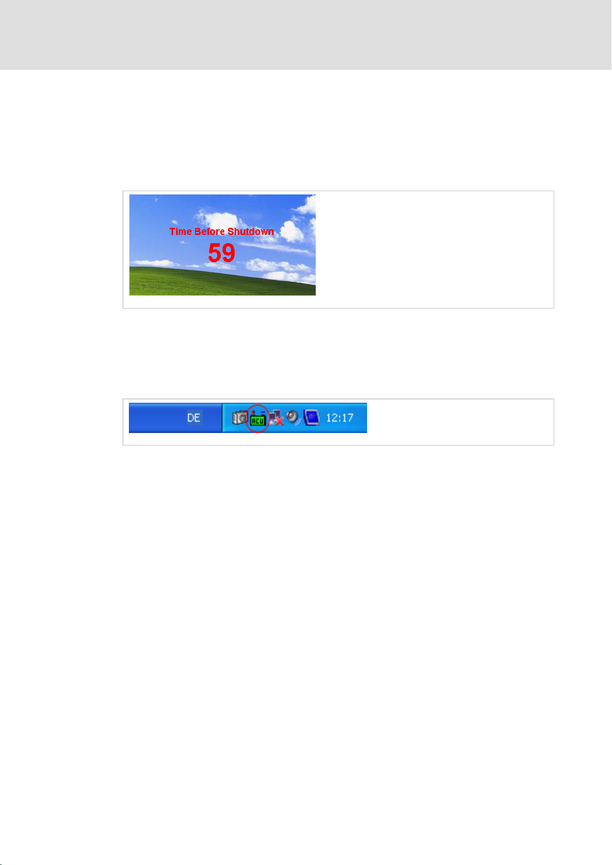
In the case of a voltage failure, the ACU UPS takes charge of the IPC supply. The remaining
time to the IPC shutdown is displayed on the desktop. (¶ 14).
Fig. 1−1 Desktop message in the event of a voltage failure
1.3.2 Message after a change in ACU UPS state
Changes in ACU UPS state are indicated by a change in colour of the ACU symbol on the
Windows task bar.
EPC50ACU−003
EPC50ACU−001
Fig. 1−2 Windows task bar with ACU UPS symbol
Legend:
Green: Battery/capacitor pack loaded and active
Yellow: Battery/capacitor pack is being loaded
Red: Indicates one or more of the following faults:
– ACU UPS is buffering the system
– Short circuit in the battery/capacitor pack
– Battery/capacitor pack is not connected
– Battery/capacitor pack is damaged
– Non−defined battery/capacitor packstatus
– Charging connection of the ACU UPS is defective
6
l
LDCDP−EPC50ACU EN 4.0
Page 7

2 Software Operation
2.1 Start and Close Software
Start
After the IPC has been booted, the software starts automatically and then runs in the
background. A symbol pops up in the information bar.
Fig. 2−1 Windows task bar with ACU UPS symbol
) Note!
If an L−force Controller is delivered with ACU UPS but without a battery pack,
the ACU UPS software is installed but UPS support is deactivated. In this case,
there will be no ACU symbol in the information bar of the Windows task bar.
In the "ACU Control" registry, UPS support can be(¶ 12)activated and
deactivated.
Software operation
Start and Close Software
2
EPC50ACU−001
Double−click the ACU symbol in the control panel to start the software manually.
Fig. 2−2 Control panel with opened ACU software window (in our example: ACU UPS V3.x)
LDCDP−EPC50ACU EN 4.0
l
EPC50ACU−011
7
Page 8

2
Software operation
Start and Close Software
Close
Usually, the software is automatically closed by Windows.
If you want to close the software manually, right−click the ACU symbol in the information
bar of the Windows task bar and select Exit from the context menu.
EPC50ACU−002
Fig. 2−3 Windows task bar with opened context menu
ACU UPS V2.x: UPS functionality is switched off until it is switched on again via the context
menu.
ACU UPS V3.x/V4.x: UPS functionality is switched off until the next system start−up.
8
l
LDCDP−EPC50ACU EN 4.0
Page 9

2.2 Open User Interface
) Note!
For configuring the ACU software, administrator rights are required.
Otherwise, only actual states can be displayed.
ƒ If you want to View ACU UPS Configuration, double−click the ACU symbol in the
information bar of the Windows task bar.
The ACU software dialog is displayed. The registries of this dialog show the ACU UPS
software settings.
Various settings which affect software only can be made (e.g. the period of time from
identifying a voltage failure to the shutdown of the IPC). Settings affecting the ACU
UPS control unit hardware cannot be made.
Software operation
Open User Interface
2
EPC50ACU−005
Fig. 2−4 Example: ACU software dialog ACU UPS V2.x
ƒ If you want to Configure the ACU UPS Control Unit, double−click on the ACU symbol
in the Windows control panel.
The ACU software dialog is also displayed. Unlike the process described above, the ACU
control registry is displayed as well which helps you configure the behaviour of the ACU
UPS control unit in the case of a voltage failure.
EPC50ACU−004
Fig. 2−5 Example: ACU software dialog ACU UPS V2.x
Information on the registries of the user interface of the various ACU UPS versions is
provided in the following chapter.
LDCDP−EPC50ACU EN 4.0
l
9
Page 10

2
2.3 User Interface Dialogs
2.3.1 Registry "ACU State" − Show UPS State
Software operation
User Interface Dialogs
Registry "ACU State" − Show UPS State
ACU USV V2.x:
Dialog Box Value Range Explanation
Type − Hardware Type
Power OK/Fail Input Voltage State; OK or Failure
UPS On/Off On: UPS functionality activated
Buffer Time [s] 0.00 ... 64.00 s Period of time to wait until a voltage failure is reported by the
Delay Time [s] 0 ... 240 s;
infinite
ACU State − Current ACU State Display
Firmware Version − Displays the current ACU firmware version
ACU UPS control unit. Thus, voltage fluctuations are filtered
out.
Maximum period of time the industrial PC can be fed by the
battery/capacitor pack, depending on the hardware.
) Note!
A change in the UPS State is displayed with a delay.
10
l
LDCDP−EPC50ACU EN 4.0
Page 11

Software operation
User Interface Dialogs
Registry "ACU State" − Show UPS State
ACU USV V3.x/V4.x:
Dialog Box Value Range Explanation
Type − Hardware Type
Power OK/Fail Input Voltage State; OK or Failure
UPS On/Off On: UPS functionality activated
Delay Time [s] 0.00 ... 64.00 s Period of time to wait until a voltage failure is reported by the
ACU UPS control unit. Thus, voltage fluctuations are filtered
out.
Buffer Time 4 min.; infinite Maximum period of time the industrial PC can be fed by the
battery/capacitor pack, depending on the hardware.
ACU State − Current ACU State Display
Firmware Version − Displays the current ACU firmware version
2
) Note!
A change in the UPS State is displayed with a delay.
LDCDP−EPC50ACU EN 4.0
l
11
Page 12

2
Software operation
User Interface Dialogs
Registry "ACU Control" − Configure UPS
2.3.2 Registry "ACU Control" − Configure UPS
) Note!
This registry is only shown when the ACU software has been called up via the
system panel. It is not shown when the software is called up by double−clicking
the symbol in the information bar of the Windows task bar.
ACU USV V2.x:
Dialog Box Value Range Explanation
Buffer Time [s] 0.00 ... 64.00 s Period of time to wait until a voltage failure is reported by the
Delay Time 0 ... 240 s;
Restart after Delay Time On/Off On: Restart or shutdown of the system when the delay time is
UPS Activated On/Off On: UPS support activated
Auto off after shutdown On/Off On: The ACU UPS control unit is switched off right after the
Backlight off after Power Fail On/Off On: Deactivates the backlight of the TFT display in case of a
infinite
ACU UPS control unit. Thus, voltage fluctuations are filtered
out.
Maximum period of time the industrial PC can be fed by the
battery/capacitor pack, depending on the hardware.
up.
Off: UPS support deactivated
shutdown of the system. This function requires a system with
ACPI support (ETX−CD).
voltage failure.
12
l
LDCDP−EPC50ACU EN 4.0
Page 13

Software operation
User Interface Dialogs
Registry "ACU Control" − Configure UPS
ACU USV V3.x:
Dialog Box Value Range Explanation
Delay Time [s] 0.00 ... 64.00 s Period of time to wait until a voltage failure is reported by the
ACU UPS control unit. Thus, voltage fluctuations are filtered
out.
Buffer Time 4 min.; infinite Maximum period of time the industrial PC can be fed by the
battery/capacitor pack, depending on the hardware.
UPS Activated On/Off On: UPS support activated
Off: UPS support deactivated
2
ACU USV V4.x:
Dialog Box Value Range Explanation
Buffer Time [s] 0.00 ... 64.00 s Period of time to wait until a voltage failure is reported by the
ACU UPS control unit. Thus, voltage fluctuations are filtered
out.
Delay Time 4 min.; infinite Maximum period of time the industrial PC can be fed by the
battery/capacitor pack, depending on the hardware.
Restart after Delay Time On/Off On: Restart or shutdown of the system when the delay time is
up.
UPS Activated On/Off On: UPS support activated
Off: UPS support deactivated
Backlight off after Power Fail On/Off On: Deactivates the backlight of the TFT display in case of a
voltage failure.
LDCDP−EPC50ACU EN 4.0
l
13
Page 14

2
Software operation
User Interface Dialogs
Registry "Time Set" − Time Before Shutdown
2.3.3 Registry "Time Set" − Time Before Shutdown
ACU UPS Vx.x:
Dialog Box Value Range Explanation
Time Before Shutdown 0 ... 60 s Period of time from identifying a mains failure by the ACU UPS
control unit until shutting down the IPC. This period of time
must be shorter than the delay time (^ 12) plus the period of
time needed by the IPC to shut down.
Example:
The IPC can be supplied for 100 s by the battery pack and needs
a maximum of 20 s for a safe shutdown.
Delay time = 100 s
Time before shutdown = < 80 s
2.3.4 Registry "Application"− Start External Programs
ACU UPS Vx.x:
While the ACU software counts down the seconds until the IPC is shut down after a voltage
failure, an external program can be started.
Dialog Box Value Range Explanation
Executable Application − Path of the executable program file of the application
[Browse] − Search executable program file
Execute Application On/Off On: The program file specified in "Executable Application" is
executed.
14
l
LDCDP−EPC50ACU EN 4.0
Page 15

Registry "Shutdown" − Force Shutdown
2.3.5 Registry "Shutdown" − Force Shutdown
ACU UPS Vx.x:
Dialog Box Value Range Explanation
Shutdown On/Off Default Setting
Force Shutdown On/Off If you are using the default setting and an application prompts
Software operation
User Interface Dialogs
you to make a user entry when shutting down the PC, the PC
cannot be shut down automatically.
If the "Force Shutdown" option is activated, all programs are
closed before the shutdown without considering feedbacks.
Caution: This setting may lead to data loss.
2
LDCDP−EPC50ACU EN 4.0
l
15
Page 16

2
2.3.6 Registry "LogFile" − View Program Messages
Software operation
User Interface Dialogs
Registry "LogFile" − View Program Messages
ACU UPS Vx.x:
All ACU software messages are recorded in the ACU.log file and can be viewed there.
Dialog Box Value Range Explanation
[Position Log File] − Select the folder the ACU.log file shall be written to.
[Show Log File] − Display ACU.log File
) Note!
The log file data is moved to the "ACU.bak" file when the file size reaches 64
KB so that the log file does not become too big.
If you delete the "ACU.log" log file through the Windows Explorer
file will be created as soon as a new log entry is available.
It may be impossible to write the log file if the software is run under a user
account with restricted access rights and if a folder other than the
preconfigured folder has been assigned. So please ensure that the user
account has the corresponding write permissions with regard to the log file
folder.
If a write filter (EWF or FBWF) is used: The log file need not be in a
write−protected area.
â
, a new log
16
l
LDCDP−EPC50ACU EN 4.0
Page 17

3 Software Installation
The ACU UPS control unit software is a factory set pre−equipment if you chose this option
when placing your purchase order and if you obtained the operating system via a Lenze
storage medium.
In other cases, start the setup program on the program CD and follow the instructions of
the setup assistent.
) Note!
After the ACU UPS software has been reinstalled, UPS functionality is
deactivated for versions V3.x/V4x and activated for version V2.x.
Software installation 3
LDCDP−EPC50ACU EN 4.0
l
17
Page 18

F
(
Ê
ü
© 06/2012
Lenze Automation GmbH
Hans−Lenze−Str. 1
D−31855 Aerzen
Germany
+49(0)51 54 /82−0
+49(0)51 54 /82 − 28 00
Lenze@Lenze.de
www.Lenze.com
Service Lenze Service GmbH
Breslauer Straße 3
D−32699 Extertal
Germany
(
Ê
008000/ 2446877 (24 h helpline)
+49(0)5154/ 82−11 12
Service@Lenze.de
LDCDP−EPC50ACU § .J41 § EN § 4.0 § TD29
10987654321
Q
 Loading...