

Lenze SMVector, AC Tech SMVector Series Operating Instructions Manual
Operating Instructions
SMVector - Frequency Inverter

1
SV01J
1 Safety Information ................................................................................... 3
2 Technical Data ......................................................................................... 6
2.1 Standards and Application Conditions ............................................................. 6
2.2 SMV Type Number Designation .......................................................................7
2.3 Ratings .............................................................................................................. 8
3 Installation .............................................................................................11
3.1 Dimensions and Mounting ..............................................................................11
3.1.1 NEMA 1 (IP31) Models < 30HP (22kW) ............................................11
3.1.2 NEMA 1 (IP31) Models > 30HP (22kW) ............................................12
3.1.3 NEMA 4X (IP65) Models ...................................................................13
3.1.4 NEMA 4X (IP65) Models with Disconnect Switch ............................. 14
3.2 Electrical Installation .......................................................................................15
3.2.1 Power Connections ........................................................................... 15
3.2.1.1 Mains Connection to 120VAC Single-Phase Supply ...........15
3.2.1.2 Mains Connection to 240VAC Single-Phase Supply ...........16
3.2.1.3 Mains Connection to Three-Phase Supply ..........................16
3.2.1.4 Motor Connection ................................................................16
3.2.1.5 Installation Recommendations for EMC Compliance..........17
3.2.1.6 NEMA 4X (IP65) Input Terminal Block ................................17
3.2.2 Fuses/Cable Cross-Sections .............................................................18
3.2.3 Control Terminals .............................................................................. 19
4 Commissioning .....................................................................................21
4.1 Local Keypad & Display ................................................................................. 21
4.2 Drive Display and Modes of Operation ..........................................................23
4.3 Parameter Setting ........................................................................................... 24
4.4 Electronic Programming Module (EPM) .........................................................24
4.5 Parameter Menu .............................................................................................25
4.5.1 Basic Setup Parameters ...................................................................25
4.5.2 I/O Setup Parameters ........................................................................29
4.5.3 Advanced Setup Parameters ............................................................33
4.5.4 PID Parameters ................................................................................. 36
4.5.5 Vector Parameters ............................................................................38
4.5.6 Network Parameters ..........................................................................40
4.5.7 Diagnostic Parameters ......................................................................40
4.5.7.1 Terminal & Protection Status Display ....................................41
4.5.7.2 Keypad Status Display ..........................................................41
4.5.8 Onboard Communications Parameters 15-30HP (11-22kW) ............42
5 Troubleshooting and Diagnostics ....................................................... 43
5.1 Status/Warning Messages ..............................................................................43
5.2 Drive Configuration Messages .......................................................................44
5.3 Fault Messages ...............................................................................................44
Appendix A ..................................................................................................... 47
A.1 Permissable Cable Lengths ............................................................................47
Contents
2
SV01J
This documentation applies to the SMV frequency inverter and contains important technical data regarding the
installation, operation, and commissioning of the inverter.
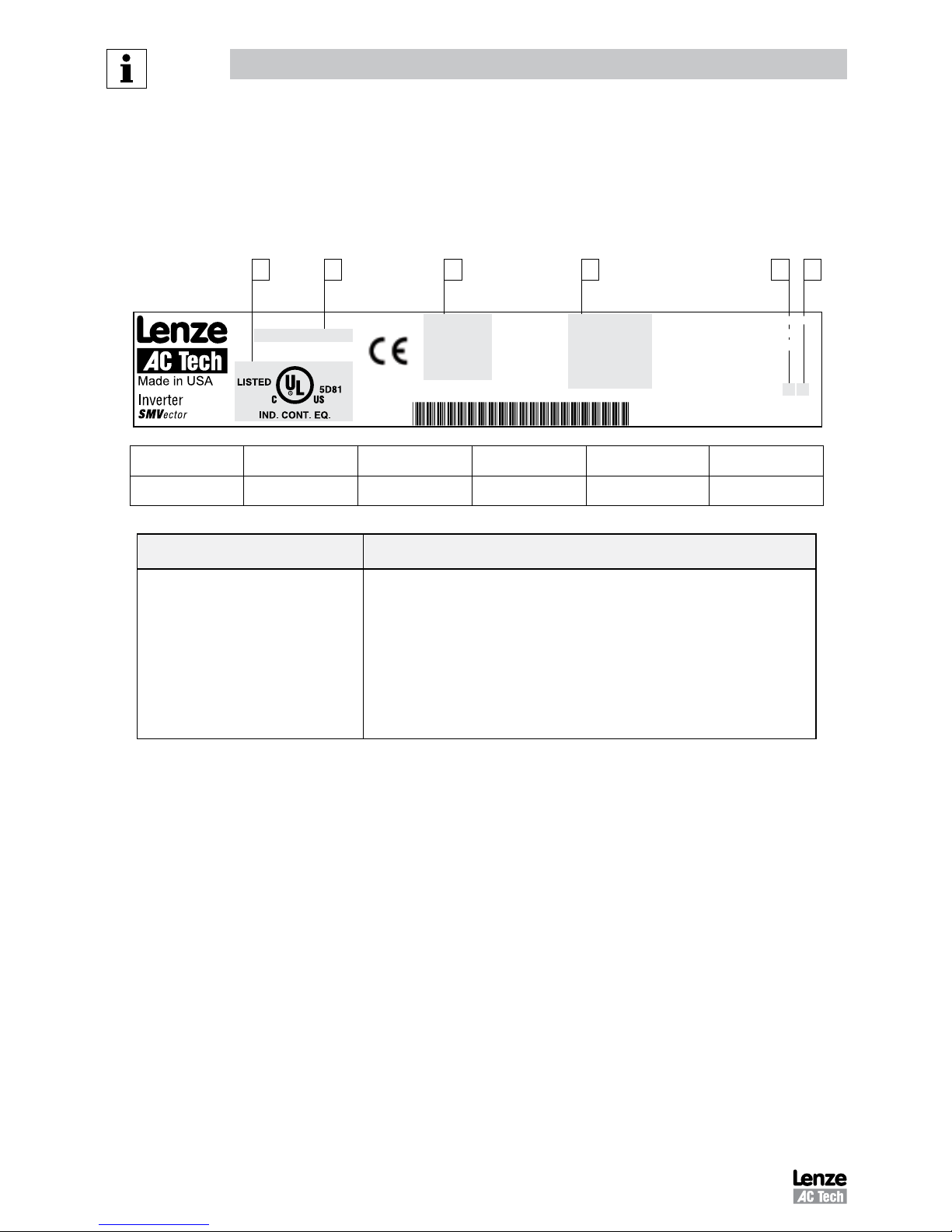
These instructions are only valid for SMV frequency inverters with software revision 2.0 or higher
(refer to drive nameplate, an example is shown below).
Please read these instructions in their entirety before commissioning the drive.
C A B D E F
Type:
ESV751N04TXB
Id-No: 00000000
INPUT:
3 (3/PE)
400/480 V
2.9/2.5 A
50-60 HZ
OUTPUT:
3 (3/PE)
0 - 400/460 V
2.4/2.1 A
0.75 KW/1HP
0 - 500 HZ
For detailed information
refer to instruction
Manual: SV01
000000000000000000
ESV751N04TXB000XX ####
TYPE-4X INDOOR USE ONLY
A B C D E F
Certifications Type Input Ratings Output Ratings Hardware Version Software Version
Scope of delivery Important
• 1 SMV Inverter
with EPM installed (see Section 4.4)
• 1 Operating Instructions manual
After receipt of the delivery, check immediately whether the items delivered match
the accompanying papers. Lenze AC Tech does not accept any liability for deficiencies
claimed subsequently.
Claim:
• visible transport damage immediately to the forwarder.
• visible deficiencies /incompleteness immediately to your Lenze AC Tech
representative
About These Instructions
Copyright © 2006 Lenze AC Tech Corporation
All rights reserved. No part of this manual may be reproduced or transmitted in any form without written permission from Lenze AC Tech
Corporation. The information and technical data in this manual are subject to change without notice. Lenze AC Tech Corporation makes no
warranty of any kind with respect to this material, including, but not limited to, the implied warranties of its merchantability and fitness for a
given purpose. Lenze AC Tech Corporation assumes no responsibility for any errors that may appear in this manual.
All information given in this documentation has been carefully selected and tested for compliance with the hardware and software described.
Nevertheless, discrepancies cannot be ruled out. Lenze AC Tech does not accept any responsibility nor liability for damages that may occur.
Any necessary corrections will be implemented in subsequent editions. This document is printed in the United States

3
SV01J
Safety Information
1 Safety Information
General
Some parts of Lenze AC Tech controllers can be electrically live and some surfaces can be hot. Non-authorized removal
of the required cover, inappropriate use, and incorrect installation or operation creates the risk of severe injury to
personnel and/or damage to equipment.
All operations concerning transport, installation, and commissioning as well as maintenance must be carried out by
qualified, skilled personnel who are familiar with the installation, assembly, commissioning, and operation of variable
frequency drives and the application for which it is being used.
Installation
Ensure proper handling and avoid excessive mechanical stress. Do not bend any components and do not change any
insulation distances during transport, handling, installation or maintenance. Do not touch any electronic components
or contacts. This drive contains electrostatically sensitive components, which can easily be damaged by inappropriate
handling. Static control precautions must be adhered to during installation, testing, servicing and repairing of this drive
and associated options. Component damage may result if proper procedures are not followed.
To ensure proper operation, do not install the drive where it is subjected to adverse environmental conditions such as
combustible, oily, or hazardous vapors; corrosive chemicals; excessive dust, moisture or vibration; direct sunlight or
extreme temperatures.
This drive has been tested by Underwriters Laboratory (UL) and is UL Listed in compliance with the UL508C Safety
Standard. This drive must be installed and configured in accordance with both national and international standards.
Local codes and regulations take precedence over recommendations provided in this and other Lenze AC Tech
documentation.
The SMVector drive is considered a component for integration into a machine or process. It is neither a machine nor
a device ready for use in accordance with European directives (reference machinery directive and electromagnetic
compatibility directive). It is the responsibility of the end user to ensure that the machine meets the applicable
standards.
Electrical Connection
When working on live drive controllers, applicable national safety regulations must be observed. The electrical
installation must be carried out according to the appropriate regulations (e.g. cable cross-sections, fuses, protective
earth [PE] connection). While this document does make recommendations in regards to these items, national and local
codes must be adhered to.
The documentation contains information about installation in compliance with EMC (shielding, grounding, filters and
cables). These notes must also be observed for CE-marked controllers. The manufacturer of the system or machine is
responsible for compliance with the required limit values demanded by EMC legislation.
Application
The drive must not be used as a safety device for machines where there is a risk of personal injury or material damage.
Emergency Stops, over-speed protection, acceleration and deceleration limits, etc must be made by other devices to
ensure operation under all conditions.
The drive does feature many protection devices that work to protect the drive and the driven equipment by generating a
fault and shutting the drive and motor down by removing power. Mains power variances can also result in shutdown of
the drive. When the fault condition disappears or is cleared, the drive can be configured to automatically restart, it is the
responsibility of the user, OEM and/or integrator to ensure that the drive is configured for safe operation.
4
SV01J
Safety Information
Explosion Proof Applications
Explosion proof motors that are not rated for inverter use lose their certification when used for variable speed. Due to
the many areas of liability that may be encountered when dealing with these applications, the following statement of
policy applies:
Lenze AC Tech Corporation inverter products are sold with no warranty of fitness for a particular purpose or warranty
of suitability for use with explosion proof motors. Lenze AC Tech Corporation accepts no responsibility for any direct,
incidental or consequential loss, cost or damage that may arise through the use of AC inverter products in these
applications. The purchaser expressly agrees to assume all risk of any loss, cost or damage that may arise from such
application.
Operation
Systems including controllers must be equipped with additional monitoring and protection devices according to the
corresponding standards (e.g. technical equipment, regulations for prevention of accidents, etc.). The controller may be
adapted to your application as described in this documentation.
DANGER!
• After the controller has been disconnected from the supply voltage, live components and power connection
must not be touched immediately, since capacitors could be charged. Please observe the corresponding notes
on the controller.
• Close all protective covers and doors prior to and during operation.
• Do not cycle input power to the controller more than once every two minutes.
• For SMVector models that are equipped with a Disconnect Switch (11th character in model number is L or M),
the Disconnect Switch is intended as a motor service disconnect and does not provide branch circuit protection
to the inverter or motor. When servicing the motor, it is necessary to wait 3 minutes after turning this switch
to the off position before working on motor power wiring as the inverter stores electrical power. To service the
inverter, it is necessary to remove mains ahead of the drive and wait 3 minutes.
Safety Notifications
All safety information given in these Operating Instructions includes a visual icon, a bold signal word and a
description.
Signal Word! (characterizes the severity of the danger)
NOTE (describes the danger and informs on how to proceed)
Icon
Signal Words
Warning of hazardous
electrical voltage
DANGER!
Warns of impending danger.
Consequences if disregarded:
Death or severe injuries.
Warning of a general danger
WARNING!
Warns of potential, very hazardous situations.
Consequences if disregarded:
Death or severe injuries.
Warning of hot surface and
risk of burn
WARNING!
Hot Surface
Warns of potential,serious situations.
Labels may be on or inside the equipment to
alert people that surfaces may reach dangerous
temperatures.
Warning of damage to
equipment
STOP!
Warns of potential damage to material and
equipment.
Consequences if disregarded:
Damage to the controller/drive or its environment.
Information
NOTE
Designates a general, useful note.
If observed, then using the controller/drive system
is made easier.
5
SV01J
Safety Information
Harmonics Notification in accordance with EN 61000-3-2, EN 61000-3-12:
Operation in public supply networks (Limitation of harmonic currents i.a.w. EN 61000-3-2, Electromagnetic Compatibility
(EMC) Limits). Limits for harmonic current emissions (equipment input current up to 16A/phase).
Directive Total Power
connected to Mains
(public supply)
Additional Measures Required for Compliance
(2)
EN 61000-3-2
< 0.5kW with mains choke
0.5 ... 1kW with active filter
> 1kW complies without additional measures
EN 61000-3-12
16 ... 75amp Additional measures are required for compliance with the standard
(1) For compliance with EMC regulations, the permissable cable lengths may change.
(2) The additional measures described only ensure that the controller meets the requirements of the EN 61000-3-2.
The machine/system manufacturer is responsible for the machine’s compliance with the regulations.
Safety Information in accordance with EN 61800-5-1:
DANGER! Hazard of Electrical Shock
Capacitors retain charge for approximately 180 seconds after power is removed. Allow at least
3 minutes for discharge of residual charge before touching the drive.
WARNING!
• This product can cause a d.c. current in the PE conductor. Where a residual current-operated (RCD) or
monitoring (RCM) device is used for protection in case of direct or indirect contact, only an RCD or RCM
Type B is allowed on the supply side of this product.
• Leakage Current may exceed 3.5mA AC. The minimum size of the PE conductor shall comply with local
safety regulations for high leakage current equipment.
• In a domestic environment, this product may cause radio interference in which case supplementary
mitigation measures may be required.
NOTE
Control and communications terminals provide reinforced insulation when the drive is connected to a power
system rated up to 300V rms between phase to ground (PE) and the applied voltage on Terminals 16 and 17 is
less than 150VAC between phase and ground.
Control and communications terminals provide basic insulation when the drive is connected to a power system
rated up to 300V between phase to ground (PE) and the applied voltage on terminals 16 and 17 is less than 250
VAC between phase phase and ground (PE).
Safety Information in accordance with UL:
Note for UL approved system with integrated controllers: UL warnings are notes which apply to UL systems. The
documentation contains special information about UL.
Warnings!
• Suitable for use on a circuit capable of delivering not more than 200,000 rms symmetrical
amperes, at the maximum voltage rating marked on the drive.
• Use minimum 75 °C copper wire only.
• Shall be installed in a pollution degree 2 macro-environment.
• NEMA 1 (IP31) models shall be installed in a pollution degree 2 macro-environment.
• All models are suitable for installation in a compartment handling Conditioned Air.
Torque Requirements (in accordance with UL) are listed in section 3.2.1, Power Connections.
6
SV01J
Technical Data
2 Technical Data
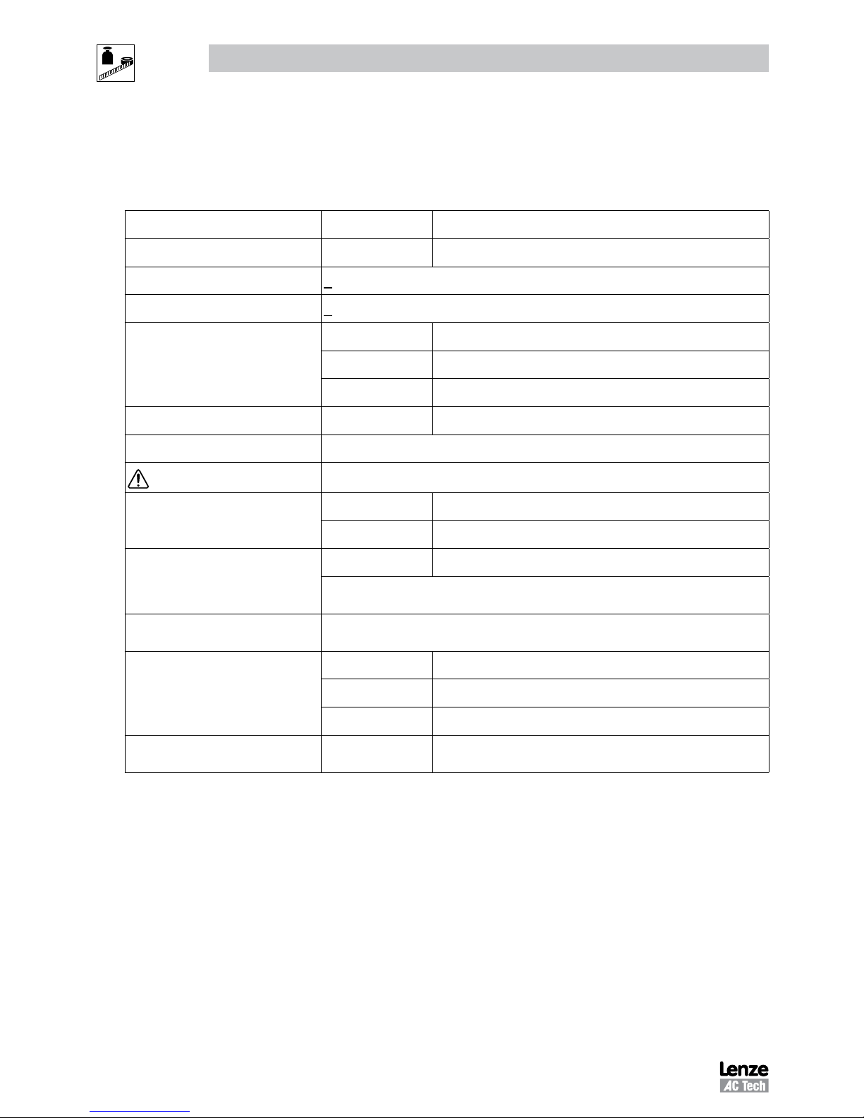
2.1 Standards and Application Conditions
Conformity
CE Low Voltage (2006/95/EC) & EMC (2004/108/EC) Directives
Approvals
UL508C Underwriters Laboratories -Power Conversion Equipment
Input voltage phase imbalance
< 2%
Humidity
< 95% non-condensing
Temperature range
Transport -25 … +70°C
Storage -20 … +70°C
Operation -10 … +55°C (with 2.5%/°C current derating above +40°C)
Installation height
0 - 4000m a.m.s.l. (with 5%/1000 m current derating above 1000m a.m.s.l.)
Vibration resistance
acceleration resistant up to 1.0g
Earth leakage current
> 3.5 mA to PE
Max Permissable Cable Length
(1)
<= 4.0 Hp (3.0 kW) 30 meters shielded, 60 meters un-shielded
=> 5.0 Hp (3.7 kW) 50 meters shielded, 100 meters un-shielded.
Enclosure
IP31/NEMA 1 IP65/NEMA 4X
NEMA 1 and NEMA 4X model enclosures are plenun rated in accordance with UL
508C and are suitable for installation in a compartment handling conditioned air.
Protection measures against
short circuit, earth fault, phase loss, over voltage, under voltage,
motor stalling, over temperature, motor overload
Compliance with EN 61000-3-2
Requirements
(2)
< 0.5kW with mains choke
0.5 ... 1kW with active filter
> 1kW without additional measures
Compliance with EN 61000-3-12
Requirements
(2)
16 ... 75amp Additional measures required for compliance with EN 61000-3-12
Operation in public supply networks (Limitation of harmonic currents i.a.w. EN 61000-3-2, Electromagnetic Compatibility
(EMC) Limits). Limits for harmonic current emissions (equipment input current up to 16A/phase).
(1) The stated cable lengths are permissible at default carrier frequencies (refer to parameter P166).
(2) The additional measures described only ensure that the controller meets the requirements of the EN 61000-3-2.
The machine/system manufacturer is responsible for the machine’s compliance with the regulations.
7
SV01J
Technical Data
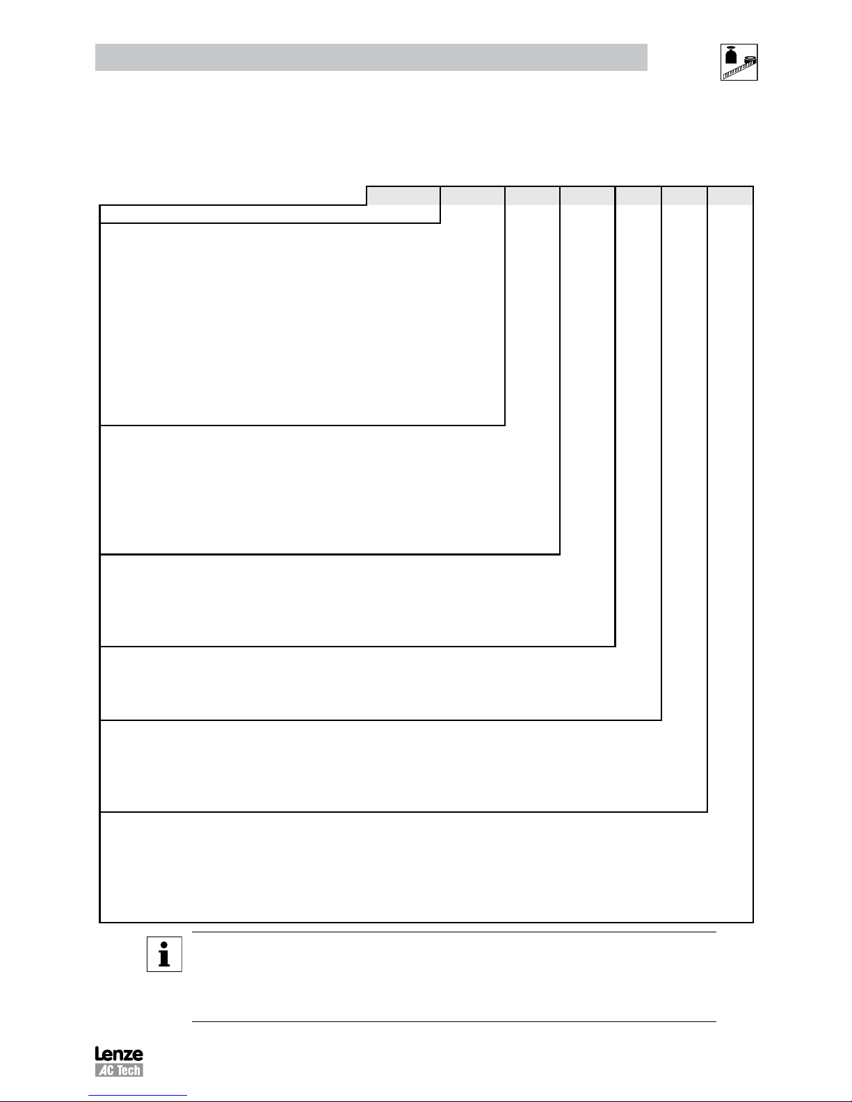
2.2 SMV Type Number Designation
The table herein describes the Type numbering designation for the SMVector Inverter models.
ESV 152 N0 2 T X B
Electrical Products in the SMVector Series
Power Rating in kW:
251 = 0.25kW (0.33HP) 113 = 11.0kW (15HP)
371 = 0.37kW (0.5HP) 153 = 15.0kW (20HP)
751 = 0.75kW (1HP) 183 = 18.5kW (25HP)
112 = 1.1kW (1.5HP) 223 = 22.0kW (30HP)
152 = 1.5kW (2HP) 303 = 30.0kW (40HP)
222 = 2.2kW (3HP) 373 = 37.5kW (50HP)
302 = 3.0kW (4HP) 453 = 45.0kW (60HP)
402 = 4.0kW (5HP)
552 = 5.5kW (7.5HP)
752 = 7.5kW (10HP)
Installed I/O & Communication Module(s):
C_ = CANopen (Available all models) The “_” blank can be:
D_ = DeviceNet (Available all models) 0 = Standard Keypad
E_ = Ethernet/IP, ModBus TCP/IP (Avail all models) N = No Keypad (NEMA 4X / IP65 only)
R_ = RS-485 / ModBus /Lecom (Avail all models)
P_ = ProfiBus-DP (Available all models)
N_ = No Communications installed (Non-IP20)
Input Voltage:
1 = 120 VAC (doubler output) or 240 VAC
2 = 240 VAC
4 = 400/480 VAC
6 = 600 VAC
Input Phase:
S = Single Phase Input only
Y = Single or Three Phase Input
T = Three Phase Input only
Input Line Filter
F = Integral EMC Filter
L = Integral EMC Filter and Integrated Disconnect Switch (NEMA 4X/IP65 Models only)
M = Integrated Disconnect Switch (NEMA 4X/IP65 Models only)
X = No EMC Filter/ No Disconnect Switch
Enclosure:
B = NEMA 1/IP31; Indoor only
C = NEMA 4X/IP65; Indoor only; Convection cooled
D = NEMA 4X/IP65; Indoor only; Fan cooled
E = NEMA 4X/IP65; Indoor/Outdoor; Convection cooled
F = NEMA 4X/IP65; Indoor/Outdoor; Fan cooled
NOTE
Prior to installation make sure the enclosure is suitable for the end-use environment
Variables that influence enclosure suitability include (but are not limited to) temperature, airborne
contaminates, chemical concentration, mechanical stress and duration of exposure (sunlight,
wind, precipitation).
8
SV01J
Technical Data
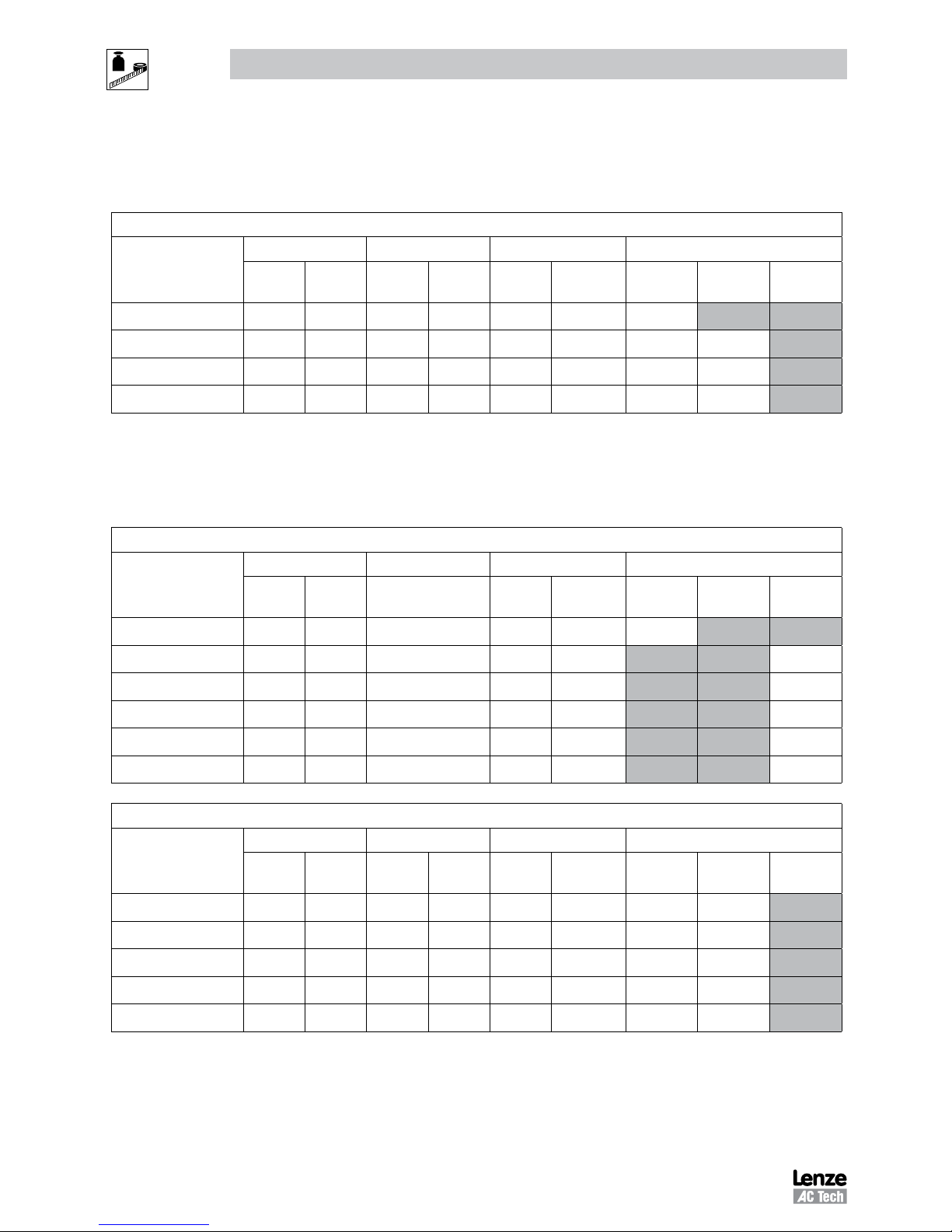
2.3 Ratings
120V / 240VAC Models
Mains = 120V Single Phase (1/N/PE) (90...132V), 240V Single Phase (2/PE) (170...264V); 48...62Hz
Type
Power Mains Current Output Current Heat Loss (Watts)
Hp kW
120VA240VACont (In)AMax I
%
N1/IP31 N4X/IP65
No filter
N4X/IP65
W/ filter
ESV251--1S-- 0.33 0.25 6.8 3.4 1.7 200 24
ESV371--1S-- 0.5 0.37 9.2 4.6 2.4 200 32 32
ESV751--1S-- 1 0.75 16.6 8.3 4.2 200 52 41
ESV112--1S-- 1.5 1.1 20 10.0 6.0 200 74 74
NOTES:
Output Current: The Output Current Maximum (%) is a percentage of the Output Current Continuous Amps (In) rating
and is adjustable in parameter P171.
240VAC Models
Mains = 240V Single Phase (2/PE) (170...264V); 48...62Hz
Type
Power Mains Current Output Current Heat Loss (Watts)
Hp kW
240V
A
Cont (I
n
)AMax I
%
N1/IP31 N4X/IP65
No filter
N4X/IP65
W/ filter
ESV251--2S-- 0.33 0.25 3.4 1.7 200 20
ESV371--2S-- 0.5 0.37 5.1 2.4 200 30
ESV751--2S-- 1 0.75 8.8 4.2 200 42
ESV112--2S-- 1.5 1.1 12.0 6.0 200 63
ESV152--2S-- 2 1.5 13.3 7.0 200 73
ESV222--2S-- 3 2.2 17.1 9.6 200 97
240V Single Phase (2/PE) (170...264V), 240V Three Phase (3/PE) (170...264V); 48...62Hz
Type
Power Mains Current Output Current Heat Loss (Watts)
Hp kW
1~ (2/PE)A3~ (3/PE)
A
Cont (In)AMax I
%
N1/IP31 N4X/IP65
No filter
N4X/IP65
W/ filter
ESV371--2Y-- 0.5 0.37 5.1 2.9 2.4 200 27 26
ESV751--2Y-- 1 0.75 8.8 5.0 4.2 200 41 38
ESV112--2Y-- 1.5 1.1 12.0 6.9 6.0 200 64 59
ESV152--2Y-- 2 1.5 13.3 8.1 7.0 200 75 69
ESV222--2Y-- 3 2.2 17.1 10.8 9.6 200 103 93
9
SV01J
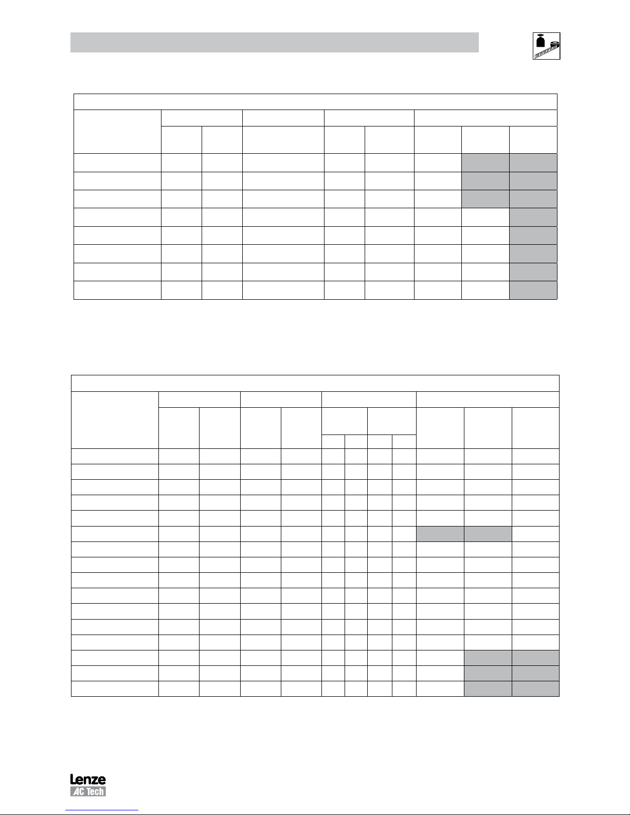
Technical Data
240V Three Phase (3/PE) (170...264V); 48...62Hz
Type
Power Mains Current Output Current Heat Loss (Watts)
Hp kW
240V
A
Cont (I
n
)AMax I
%
N1/IP31 N4X/IP65
No filter
N4X/IP65
W/ filter
ESV112--2T-- 1.5 1.1 6.9 6 200 64
ESV152--2T-- 2 1.5 8.1 7 200 75
ESV222--2T-- 3 2.2 10.8 9.6 200 103
ESV402--2T-- 5 4.0 18.6 16.5 200 154 139
ESV552--2T-- 7.5 5.5 26 23 200 225 167
ESV752--2T-- 10 7.5 33 29 200 274 242
ESV113--2T-- 15 11 48 42 180 485 468
ESV153--2T-- 20 15 59 54 180 614 591
NOTES:
Output Current: The Output Current Maximum (%) is a percentage of the Output Current Continuous Amps (In) rating
and is adjustable in parameter P171.
400...480VAC Models
400 ... 480V Three Phase (3/PE) (400V: 340...440V), (480V: 340...528V); 48...62Hz
Type
Power Mains Current Output Current Heat Loss (Watts)
Hp kW
400VA480VACont (In)AMax I
%
N1/IP31 N4X/IP65
No filter
N4X/IP65
W/ filter
400V 480V 400V 480V
ESV371--4T-- 0.5 0.37 1.7 1.5 1.3 1.1 175 200 23 21 25
ESV751--4T-- 1 0.75 2.9 2.5 2.4 2.1 175 200 37 33 37
ESV112--4T-- 1.5 1.1 4.2 3.6 3.5 3.0 175 200 48 42 46
ESV152--4T-- 2 1.5 4.7 4.1 4.0 3.5 175 200 57 50 54
ESV222--4T-- 3 2.2 6.1 5.4 5.5 4.8 175 200 87 78 82
ESV302--4T-- 4 3.0 8.3 7.0 7.6 6.3 175 200 95
ESV402--4T-- 5 4.0 10.6 9.3 9.4 8.2 175 200 128 103 111
ESV552--4T-- 7.5 5.5 14.2 12.4 12.6 11.0 175 200 178 157 165
ESV752--4T-- 10 7.5 18.1 15.8 16.1 14.0 175 200 208 190 198
ESV113--4T-- 15 11 27 24 24 21 155 180 418 388 398
ESV153--4T-- 20 15 35 31 31 27 155 180 493 449 459
ESV183--4T-- 25 18.5 44 38 39 34 155 180 645 589 600
ESV223--4T-- 30 22 52 45 46 40 155 180 709 637 647
ESV303--4T-- 40 30 68 59 60 52 180 1020
ESV373--4T-- 50 37.5 85 74 75 65 180 1275
ESV453--4T-- 60 45 100 87 88 77 180 1530
NOTES:
Output Current: The Output Current Maximum (%) is a percentage of the Output Current Continuous Amps (In) rating
and is adjustable in parameter P171.
For 400...480 VAC models, the output current maximum (%) in the 400V column is used when P107 = 0
For 400...480 VAC models, the output current maximum (%) in the 480V column is used when P107 = 1

10
SV01J
Technical Data
600VAC Models
600V Three Phase (3/PE) (425...660V); 48...62Hz
Type
Power Mains Current Output Current Heat Loss (Watts)
Hp kW A
Cont (In)AMax I
%
N1/IP31 N4X/IP65
No filter
N4X/IP65
W/ filter
ESV751--6T-- 1 0.75 2 1.7 200 37 31
ESV152--6T-- 2 1.5 3.2 2.7 200 51 43
ESV222--6T-- 3 2.2 4.4 3.9 200 68 57
ESV402--6T-- 5 4 6.8 6.1 200 101 67
ESV552--6T-- 7.5 5.5 10.2 9 200 148 116
ESV752--6T-- 10 7.5 12.4 11 200 172 152
ESV113--6T-- 15 11 19.7 17 180 380 356
ESV153--6T-- 20 15 25 22 180 463 431
ESV183--6T-- 25 18.5 31 27 180 560 519
ESV223--6T-- 30 22 36 32 180 640 592
ESV303--6T-- 40 30 47 41 180 930
ESV373--6T-- 50 37.5 59 52 180 1163
ESV453--6T-- 60 45 71 62 180 1395
NOTES:
Output Current: The Output Current Maximum (%) is a percentage of the Output Current Continuous Amps (In) rating
and is adjustable in parameter P171.
STOP!
• For installations above 1000m a.m.s.l., derate In by 5% per 1000m, do not
exceed 4000m a.m.s.l.
• Operation above 40°C, derate In by 2.5% per °C, do not exceed 55°C.
Output Current (In) derating for Carrier Frequency (P166) for NEMA 1 (IP31) Models:
- If P166=2 (8 kHz), derate In to 92% of drive rating
- If P166=3 (10 kHz), derate In to 84% of drive rating
Output Current (In) derating for Carrier Frequency (P166) for NEMA 4X (IP65) Models:
- If P166=1 (6 kHz), derate In to 92% of drive rating
- If P166=2 (8 kHz), derate In to 84% of drive rating
- If P166=3 (10 kHz), derate In to 76% of drive rating
11
SV01J
Installation
3 Installation
3.1 Dimensions and Mounting
WARNING!
Drives must not be installed where subjected to adverse environmental conditions such as: combustible, oily, or
hazardous vapors; corrosive chemicals; excessive dust, moisture or vibration; direct sunlight or extreme temperatures.
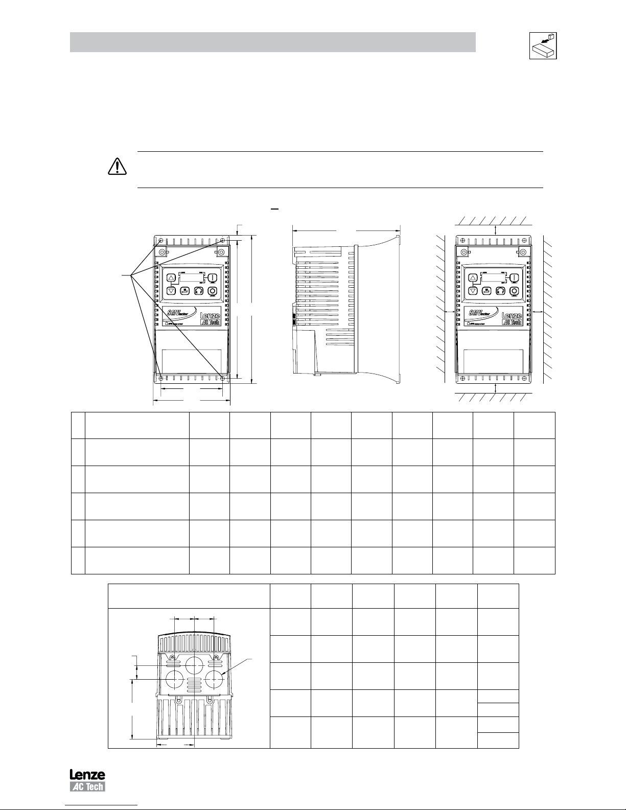
3.1.1 NEMA 1 (IP31) Models < 30HP (22kW)
b2
b1
b
a
a1
c
s1 s1
s2
s2
Mounting Screws
4 x #10
18 lb-in
4 x M5
20 Nm
( )
Type
a
in (mm)
a1
in (mm)b in (mm)
b1
in (mm)
b2
in (mm)c in (mm)
s1
in (mm)
s2
in (mm)m lb (kg)
G1
ESV251~~~~~B; ESV371~~~~~B
ESV751~~~~~B
3.90 (99) 3.12 (79) 7.48 (190) 7.00 (178) 0.24 (6) 4.35 (111) 0.6 (15) 2.0 (50) 2.0 (0.9)
G2
ESV112~~~~~B; ESV152~~~~~B
ESV222~~~~~B
3.90 (99) 3.12 (79) 7.52 (191) 7.00 (178) 0.26 (7) 5.45 (138) 0.6 (15) 2.0 (50) 2.8 (1.3)
G3 ESV402~~~~~B 3.90 (99) 3.12 (79) 7.52 (191) 7.00 (178) 0.30 (8) 5.80 (147) 0.6 (15) 2.0 (50) 3.2 (1.5)
H1 ESV552~~~~~B; ESV752~~~~~B 5.12 (130) 4.25 (108) 9.83 (250) 9.30 (236) 0.26 (7) 6.30 (160) 0.6 (15) 2.0 (50) 6.0 (2.0)
J1
ESV113~~~~~B; ESV153~~~~~B
ESV183~~~~~B; ESV223~~~~~B
6.92 (176) 5.75 (146) 12.50 (318) 11.88 (302) 0.31 (8) 8.09 (205) 0.6 (15) 2.0 (50) 13.55 (6.15)
Conduit Hole Dimensions Type
N
in (mm)P in (mm)
P1
in (mm)Q in (mm)S in (mm)
Q
N
Q
P
S
P1
G1 1.84 (47) 1.93 (49) .70 (18) 1.00 (25) .88 (22)
G2 1.84 (47) 3.03 (77) .70 (18) 1.00 (25) .88 (22)
G3 1.84 (47) 3.38 (86) .70 (18) 1.00 (25) .88 (22)
H1 2.46 (62) 3.55 (90) .13 (3) 1.38 (35)
1.13 (29)
.88 (22)
J1 3.32 (84) 4.62 (117) .73 (19) 1.40 (36)
1.31 (33)
.88 (22)
12
SV01J
Installation
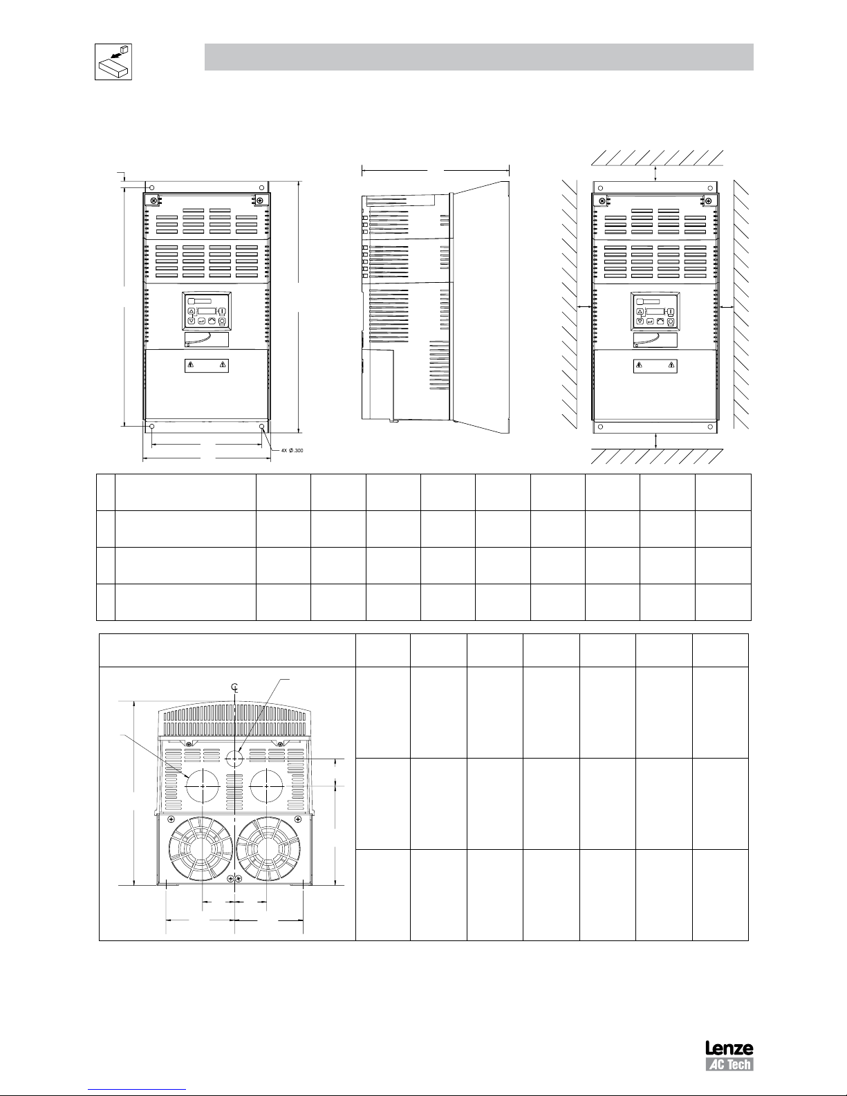
3.1.2 NEMA 1 (IP31) Models > 30HP (22kW)
c
s1
s2
s2
s1
b
a
a1
b1
b2
SMV
SMV
Type
a
in (mm)
a1
in (mm)b in (mm)
b1
in (mm)
b2
in (mm)c in (mm)
s1
in (mm)
s2
in (mm)m lb (kg)
K1
ESV303~~4~~B;
ESV303~~6~~B
8.72 (221) 7.50 (190) 14.19 (360) 13.30 (338) 0.45 (11.4) 10.07 (256) 0.6 (15) 2.0 (50) 24 (10.9)
K2
ESV373~~4~~B;
ESV373~~6~~B
8.72 (221) 7.50 (190) 17.19 (436) 16.30 (414) 0.45 (11.4) 10.07 (256) 0.6 (15) 2.0 (50) 31 (14.1)
K3
ESV453~~4~~B
ESV453~~6~~b
8.72 (221) 7.50 (190) 20.19 (513) 19.30 (490) 0.45 (11.4) 10.07 (256) 0.6 (15) 2.0 (50) 35 (15.9)
Conduit Hole Dimensions Type
N
in (mm)P in (mm)
P1
in (mm)Q in (mm)S in (mm)
S1
in (mm)
P1
P
S1
S
C
Q
N
Q
N
K1 3.75 (95) 5.42 (137) 1.50 (38.1) 1.75 (44.4) 1.75 (44.4) 0.875 (22.2)
K2 3.75 (95) 5.42 (137) 1.50 (38.1) 1.75 (44.4) 1.75 (44.4) 0.875 (22.2)
K3 3.75 (95) 5.42 (137) 1.50 (38.1) 1.75 (44.4) 1.75 (44.4) 0.875 (22.2)

13
SV01J
Installation
3.1.3 NEMA 4X (IP65) Models
b2
b1
b
a1
a
c
s1
s2
s2
s1
Mounting Screws
4 x #8 32
10 lb in
4 x M4
1 2 Nm
( )
Type
a
in (mm)
a1
in (mm)b in (mm)
b1
in (mm)
b2
in (mm)c in (mm)
s1
in (mm)
s2
in (mm)m lb (kg)
R1
ESV371N01SX_; ESV751N01SX_;
ESV371N02YX_; ESV751N02YX_;
ESV371N04TX_; ESV751N04TX_;
ESV751N06TX_; ESV371N02SF_;
ESV751N02SF_; ESV371N04TF_;
ESV751N04TF_;
6.28 (160) 5.90 (150) 8.00 (203) 6.56 (167) 0.66 (17) 4.47 (114) 2.00 (51) 2.00 (51) 3.6 (1.63)
R2
ESV112N01SX_; ESV112N02YX_;
ESV152N02YX_; ESV112N04TX_;
ESV152N04TX_; ESV222N04TX_;
ESV152N06TX_; ESV222N06TX_;
ESV112N02SF_; ESV152N02SF_;
ESV112N04TF_; ESV152N04TF_;
ESV222N04TF_; ESV302N04TF_;
6.28 (160) 5.90 (150) 8.00 (203) 6.56 (167) 0.66 (17) 6.31 (160) 2.00 (51) 2.00 (51) 5.9 (2.68)
S1 ESV222N02YX_; ESV222N02SF_ 7.12 (181) 6.74 (171) 8.00 (203) 6.56 (167) 0.66 (17) 6.77 (172) 2.00 (51) 2.00 (51) 7.1 (3.24)
T1
ESV552N02TX~; ESV752N02TX~
ESV752N04TX~; ESV752N06TX~;
ESV752N04TF~
8.04 (204) 7.56 (192) 10.00 (254) 8.04 (204) 0.92 (23) 8.00 (203) 4.00 (102) 4.00 (102) 10.98 (4.98)
V1
ESV402N02TX_; ESV402N04TX_;
ESV552N04TX_; ESV402N06TX_
ESV552N06TX_; ESV402N04TF_;
ESV552N04TF_
8.96 (228) 8.48 (215) 10.00 (254) 8.04 (204) 0.92 (23) 8.00 (203) 4.00 (102) 4.00 (102) 11.58 (5.25)
W1
ESV113N02TX~; ESV153N02TX~
ESV113N04TX~; ESV153N04TX~
ESV113N04TF~; ESV153N04TF~
ESV113N06TX~; ESV153N06TX~
ESV183N04TX~; ESV183N04TF~
ESV183N06TX~
9.42 (240) 8.94 (228) 14.50 (368) 12.54 (319) 0.92 (24) 9.45 (241) 4.00 (102) 4.00 (102) 22.0 (10.0)
X1
ESV223N04TX~; ESV223N04TF~
ESV223N06TX~
9.42 (240) 8.94 (228) 18.5 (470) 16.54 (420) 0.92 (24) 9.45 (241) 4.00 (102) 4.00 (102) 25.5 (11.6)
_ = Last digit of part number: C = N4X Indoor (convection cooled) ~ = Last digit of part number: D = N4X Indoor (fan cooled)
E = N4X In/Outdoor (convection cooled) F = N4X In/Outdoor (fan cooled)
Conduit Hole Dimensions Type
N
in (mm)P in (mm)Q in (mm)S in (mm)
S1
in (mm)
P
N
Q
Q
S
S
S1
P
Q
Q
N
R1 3.14 (80) 2.33 (59) 1.50 (38) .88 (22) n/a
R2 3.14 (80) 4.18 (106) 1.50 (38) .88 (22) n/a
S1 3.56 (90) 4.63 (118) 1.50 (38) .88 (22) n/a
T1 4.02 (102) 5.00 (127) 1.85 (47) 1.06 (27) n/a
V1 4.48 (114) 5.00 (127) 1.85 (47) 1.06 (27) n/a
W1 4.71 (120) 5.70 (145) 2.00 (51) 1.375 (35) 1.125 (28)
X1 4.71 (120) 5.70 (145) 2.00 (51) 1.375 (35) 1.125 (28)

14
SV01J
Installation
3.1.4 NEMA 4X (IP65) Models with Disconnect Switch
b2
b
b1
a
a1
c
c1
s1
s2
s2
s1
Mounting Screws
4 x #8 32
10 lb in
4 x M4
1 2 Nm
( )
Type
a
in
(mm)
a1
in
(mm)
b
in
(mm)
b1
in
(mm)
b2
in
(mm)
c
in
(mm)
c1
in
(mm)
s1
in
(mm)
s2
in
(mm)
m
lb
(kg)
AA1
ESV371N01SM_; ESV371N02YM_;
ESV371N02SL_; ESV371N04TM_;
ESV371N04TL_; ESV371N06TM_;
ESV751N01SM_; ESV751N02YM_;
ESV751N02SL_; ESV751N04TM_;
ESV751N04TL_; ESV751N06TM_;
6.28
(160)
5.90
(150)
10.99
(279)
9.54
(242)
0.66
(17)
4.47
(114)
.86
(22)
2.00
(51)
2.00
(51)
4.7
(2.13)
AA2
ESV112N01SM_; ESV112N02YM_;
ESV112N02SL_; ESV112N04TM_;
ESV112N04TL_; ESV152N02YM_;
ESV152N02SL_; ESV152N04TM_;
ESV152N04TL_; ESV152N06TM_;
ESV222N04TM_; ESV222N04TL_;
ESV222N06TM_; ESV302N04TL_;
6.28
(160)
5.90
(150)
10.99
(279)
9.54
(242)
0.66
(17)
6.31
(160)
.86
(22)
2.00
(51)
2.00
(51)
7.9
(3.58)
AD1 ESV222N02SL_; ESV222N02YM_;
7.12
(181)
6.74
(171)
10.99
(279)
9.54
(242)
0.66
(17)
6.77
(172)
.86
(22)
2.00
(51)
2.00
(51)
9.0
(4.08)
AB1
ESV552N02TM~; ESV752N02TM~
ESV752N04TM~; ESV752N06TM~;
ESV752N04TL~
8.04
(204)
7.56
(192)
13.00
(330)
11.04
(280)
0.92
(23)
8.00
(203)
.86
(22)
4.00
(102)
4.00
(102)
13.9
(6.32)
AC1
ESV402N02TM_; ESV402N04TM_;
ESV552N04TM_; ESV402N06TM_;
ESV552N06TM_; ESV402N04TL_;
ESV552N04TL_
8.96
(228)
8.48
(215)
13.00
(330)
11.04
(280)
0.92
(23)
8.04
204)
.86
(22)
4.00
(102)
4.00
(102)
14.7
(6.66)
AE1
ESV113N04TM~; ESV153N04TM~,
ESV113N06TM~; ESV153N06TM~
9.42
(240)
8.94
(228)
14.50
(368)
12.54
(319)
0.92
(24)
9.45
(241)
0.73
(19)
4.00
(102)
4.00
(102)
23.0
(10.4)
AF1
ESV113N02TM~; ESV153N02TM~
ESV113N04TL~; ESV153N04TL~
ESV183N04TL~; ESV223N04TL~
ESV183N04TM~; ESV223N04TM~
ESV183N06TM~; ESV223N06TM~
9.42
(240)
8.94
(228)
18.5
(470)
16.54
(420)
0.92
(24)
9.45
(241)
0.73
(19)
4.00
(102)
4.00
(102)
28.5
(12.9)
_ = Last digit of part number: C = N4X Indoor (convection cooled) ~ = Last digit of part number: D = N4X Indoor (fan cooled)
Conduit Hole Dimensions Type
N
in (mm)P in (mm)Q in (mm)S in (mm)
S1
in (mm)
Q Q
P
N
S
S
S1
P
Q
Q
N
AA1 3.14 (80) 2.33 (59) 1.50 (38) .88 (22) n/a
AA2 3.14 (80) 4.18 (106) 1.50 (38) .88 (22) n/a
AD1 3.56 (90) 4.63 (118) 1.50 (38) .88 (22) n/a
AB1 4.02 (102) 5.00 (127) 1.85 (47) 1.06 (27) n/a
AC1 4.48 (114) 5.00 (127) 1.85 (47) 1.06 (27) n/a
AE1 4.71 (120) 5.70 (145) 2.00 (51) 1.375 (35) 1.125 (28)
AF1 4.71 (120) 5.70 (145) 2.00 (51) 1.375 (35) 1.125 (28)
 Loading...