

Page 1
K-HB 13.0001-EN
.1kj
Ä.1kjä
L-force Drives
Communication Manual
Servo Drives 930 fluxxtorque
931M/W
PROFIBUS-DP
Page 2

This documentation is valid for 931M/W servo inverters.
Document history
Material No. Version Description
.1kj 2.1 10/2006 TD14 First edition
0Fig.0Tab. 0
Tip!
Current documentation and software updates concerning Lenze products can be found on
the Internet in the ”Services & Downloads” area under
http://www.Lenze.com
Important note:
Software is provided to the user ”as is”. All risks regarding the quality of the software and any results obtained from its use
remain with the u ser. The user should take appropriate security precautions against possible maloperation.
We do not accept any responsibility for direct or indirect damage caused, e.g. loss of profit, loss of orders or adverse
commercial effects of any kind.
All trade names listed in this documentation are trademarks of their respective owners.
© 2006 Lenze GmbH & Co KG Kleinantriebe, Hans-Lenze-Straße 1, D-32699 Extertal
No part of this documentation may be reproduced or made accessible to third parties without written consent by Lenze GmbH &
Co KG Kleinantriebe.
All information given in this documen tation has been selected carefully and complies with the hardware and software described.
Nevertheless, discrepancies cannot be ruled out. We do not take any responsibility or liability for any damage that may occur.
Necessary corrections will be included in subsequent editions.
2
K-HB 13.0001-EN 2.1
Page 3

Contents i
1Preface 6..................................................................
1.1 Introduction 6.........................................................
1.2 Comparison of industrial fieldbus systems 7...............................
1.3 About this Communication Manual 8.....................................
1.4 Legal regulations 9.....................................................
2 Safety instructions 10.........................................................
2.1 Persons responsible for safety 10..........................................
2.2 General safety instructions 11.............................................
2.3 Definition of notes used 12...............................................
3 Technical data 13............................................................
3.1 General data and operating conditions 13..................................
4 Electrical installation 14.......................................................
4.1 Electrical connection of the servo inverter with the PROFIBUS master 17.........
5 Commissioning 18...........................................................
5.1 Before switching on 18..................................................
5.2 Activation of PROFIBUS at the servo inverter 18..............................
5.3 PROFIBUS settings in the operating program 22..............................
5.4 PROFIBUS communication 25.............................................
5.4.1 GSE file for PROFIBUS connection 25................................
5.4.2 Hardware configuration 25.......................................
5.4.3 Structure of communication channel 26.............................
6 Control word and status word (Profidrive state machine) 27........................
6.1 General information 27..................................................
6.2 Control word 28........................................................
6.3 The status word (ZSW) 31................................................
6.4 The Profidrive state machine 33...........................................
6.4.1 State machine and general state diagram 33........................
6.4.2 Example: State machine for speed operation 36......................
6.4.3 State diagram for positioning 38...................................
6.4.4 State diagram for speed control 40.................................
K-HB 13.0001-EN 2.1
3
Page 4

Contentsi
7 Parameter channel (PCV mechanism) 41.........................................
7.1 Access authorisation 41..................................................
7.2 Structure of the parameter characteristic value 42............................
7.2.1 Structure of parameter identification (PKE) 42.......................
7.2.2 Subindex 42....................................................
7.2.3 Parameter value 42..............................................
7.3 Job and response processing 43...........................................
7.3.1 Job identification (master -> slave) 43..............................
7.3.2 Response identification (slave -> master) 44.........................
7.3.3 Error numbers at response 45.....................................
7.3.4 Examples of PCV mechanism 46...................................
7.3.5 Transfer of PPO with PROFIBUS-DP 50..............................
8 Parameter numbers 51........................................................
8.1 Explanation of the parameter numbers 51..................................
8.1.1 Node address (PNU 918) 51.......................................
8.1.2 Parameter change rights (PNU 927) 52..............................
8.1.3 Control authority (PNU 928) 52....................................
8.1.4 Selector switch for operating mode (PNU 930) 52.....................
8.1.5 Selector switch - control word bit 8 (PNU 931) 53.....................
8.1.6 Selector switch - control word bit 9 (PNU 932) 54.....................
8.1.7 Selector switch - control word bit 11 (PNU 933) 54....................
8.1.8 Selector switch - control word bit 12 ... 15 (PNU 934 ... 937) 54..........
8.1.9 Selector switch - status word bit 8 (PNU 938) 55......................
8.1.10 Selector switch - status word bit 11 (PNU 939) 56.....................
8.1.11 Selector switch - status word bit 12 (PNU 940) 56.....................
8.1.12 Selector switch - status word bit 13 (PNU 941) 57.....................
8.1.13 Selector switch - status word bit 14 (PNU 942) 57.....................
8.1.14 Selector switch - status word bit 15 (PNU 943) 57.....................
8.2 Device-specific parameter numbers 58.....................................
8.2.1 Data type - jogging setpoint 1 and 2 (PNU 107 und 108) 58............
8.2.2 Fault number (PNU 947) 58.......................................
8.2.3 Load parameter set (PNU 970) 59..................................
8.2.4 Transfer to the non-volatile memory (PNU 971) 59....................
8.3 Overview of the device-specific active parameters 60.........................
8.4 Overview of the device-specific passive parameters 60........................
8.5 Data type - travel data record (PNU 1 to 100) 61..............................
8.6 Data type - reference parameter (PNU 101) 62...............................
8.7 Data type - IO settings (PNU 102) 63.......................................
8.8 Data type - control parameters (PNU 103) 65................................
8.9 Data type - system parameters (PNU 104) 65................................
4
K-HB 13.0001-EN 2.1
Page 5

Contents i
8.10 Data type - service parameters (PNU 105) 66................................
8.11 Data type - PROFIBUS parameters (PNU 106) 67..............................
8.12 Data type status (PNU 1000) 68...........................................
8.13 Data type info (PNU 1001) 71.............................................
8.14 Data type options (PNU 1002) 71..........................................
8.15 Overview of all PNUs 72..................................................
9 Troubleshooting and fault elimination 76.......................................
10 Appendix 77................................................................
10.1 Data formats 77........................................................
10.2 GSE file 77.............................................................
11 Index 80....................................................................
K-HB 13.0001-EN 2.1
5
Page 6

1
Preface
Introduction
1Preface
1.1 Introduction
The competitive situation in the mechanical and system engineering sector requires new
means to optimise the production costs. This is why modular machine and system
engineering is becoming increasingly more important, since individual solutions can now
be set up easily and cost-effectively from a single modular system.
Lenze fieldbus systems in industrial applications
For an optimal communication between the single modules of a system, fieldbus systems
are increasingly used for process automation. Lenze offers the following communication
modules for the standard fieldbus systems:
ƒ Profibus DP
ƒ CANOpen
Decision support
The decision for a fieldbus system depends on many different factors. The following
overviews will help you to find the solution for your application.
Profibus DP
For bigger machines with bus lengths of more than 100 metres, INTERBUS or PROFIBUS-DP
(PROFIBUS-Decentralised Periphery) are frequently used. The PROFIBUS-DP is always used
together with a master control (PLC) – here the PROFIBUS master transmits e.g. the
setpoints to the single PROFIBUS stations (e. g. Lenze controllers).
When using the data transfer rate of 1.5 Mbits/s typical for the PROFIBUS-DP, thesensors
and actuators receive the process data. Due to the data transmission mode and the
telegram overhead, a bus cycle time results at 1.5 Mbits/s, which is sufficient to control
e. g. conveyors. If, for technical reasons, the process data must be transmitted faster to the
sensors and actuators, the PROFIBUS can also be operated with a data transmission rate
of maximally 12 Mbit/s.
CANOpen
CANopen is a communication protocol specified to the CiA (CAN in Automation) user
group. Lenze can provide communication modules for communicating with CANopen
masters. These modules are compatible with the specification DS 301 V4.01.
6
K-HB 13.0001-EN 2.1
Page 7

Comparison of industrial fieldbus systems
1.2 Comparison of industrial fieldbus systems
Preface
1
Topology
Bus
management
Max. number
of nodes
(master and
slaves)
Max. distance
between
stations
without
repeater
Max. distance
between
stations with
repeater
Transmission
medium
Auxiliary
energy supply
via bus cable
Baud rate
Typical update
time (e.g. 8
stations, 4
Bytes user
data)
Telegram
length (user
data)
Telegram
length (total)
Bus access
methods
CAN /
DeviceNet Profibus DP AS-i INTERBUS INTERBUS-Loop LON
CANopen
Line with
terminating
resistors
Multi master Single master Single master Single master Single master Only together with
64 64 124 (4 segments,3
Dependent on the
baud rate used
1km(50kbit/s)
25 m (1 Mbit/s)
General length
reduction,
dependenton the
repeater used
Shielded, twisted
pair cable
Possible via
additional wires in
the bus cable
10 kbit/s - 1 Mbit/s 125 kbit/s,
Approx. 1.32 ms at
1Mbit/s(high
priority)
0to8bytes 0to8bytes 0to 246 bytes 4bits 1to64bytesdata,
106 bits at 8 bytes
user data
CSMA/CA
message-oriented
Line with
terminating
resistors
100 m (500 kbit/s)
250 m (250 kbit/s)
500 m (125 kbit/s)
Not specified 10 km (93.75
Shielded, twisted
pair cable
Possible via
additional wires in
the bus cable
250 kbit/s,
500 kbit/s
Approx. 2.64 ms at
500 kbit/s (high
priority)
106 bits at 8 bytes
user data
CSMA/CA
message-oriented
Line with
terminating
resistors
repeaters),
max. 32 per
segment
1.2 km (93.75
kbit/s)
100 m (12 Mbit/s)
kbit/s)
Shielded, twisted
pair cable
Possible via
additional wires in
the bus cable
9.6 kbit/s - 12
Mbit/s
Approx. 2.5 ms at
500 kbit/s
User data +
6to11bytes
Cyclic polling Cyclic polling Time base /
Line, tree, ring
(possible)
124
sensors/actuators
1master
100 m 1.5 m (local bus)
300 m (2
repeaters)
Unshielded,
untwisted flat pair
cable
Current supply via
data cable
(2 to 8 A)
167 kbit/s 500 kbit/s or
Typically 5 ms
(4 bits each)
21 bits, of which:
14 bits master, 7
bits slave
Ring Ring Line (2 wire) or any
512 slaves,
1master
400 m (remote
bus)
2.5 km (optical
fibre)
13 km (remote
bus),
100 km (optical
fibre)
Shielded, twisted
5-wire cable
Optical fibre,
infrared
Separate, Group
via bus terminal
(remote bus)
2Mbit/s
At least 2 ms
(process data)
up to 246 bytes
parameters
User data +
6bytes
distributed shift
register
INTERBUS-S; single
master (bus
terminal)
32 slaves 32385 stations
10 m (max. 100 m
cable length
without repeater)
No repeater
required
Unshielded, twisted
pair cable
Current supply via
data cable
(ca. 1.5 A)
500 kbit/s 78 kbit/s - 1.25
At least 2 ms
(process data)
1to64bytesdata,
up to 246 bytes
parameters
User data +
6bytes
Time base /
distributed shift
register
Tab. 1 Comparison of industrial fieldbus systems
other
Multi master
distributed to 255
subnetworks with
127 stations each
2kmat78kbit/s
(twisted pair),
6.1 km at 5.48
kbit/s (optical fibre
plastics)
Almost any,
expandable by
subnetworks (no
repeater)
Unshielded,
untwisted pair
cable
Radio, optical fibre,
power supply
system (Powerline)
possible via
additional wires in
the bus cable
Mbit/s
Approx. 70 ms
1to228bytes
data,
Typically approx.
11 bytes
max. 255 bytes,
User data + 27
bytes
Modified
CSMA/CD
K-HB 13.0001-EN 2.1
7
Page 8

1
Preface
About this Communication Manual
1.3 About this Communication Manual
Target group
This Manual is intended for all persons who plan, install, commission, and set servo
inverters of the 931M/W series.
Together with the catalogue, it forms the basis for project planning for the mechanical
engineer and system engineer.
Contents
The PROFIBUS Manual complements the Mounting Instructions and Software Manual
included in the scope of supply:
ƒ The features and functions are described in detail.
ƒ It provides detailed information on possible applications.
ƒ Parameter setting is clarified by means of examples.
ƒ In case of doubt, the supplied Mounting Instructions are always valid.
How to find information
ƒ The table of contents and the index help you to find information on a certain topic.
ƒ Descriptions and data with regard to further Lenze products can be gathered from
the respective catalogues, Operating Instructions, and Manuals.
ƒ You can request Lenze documentation from your responsible Lenze sales partner or
download it as a PDF file from the Internet.
8
K-HB 13.0001-EN 2.1
Page 9

1.4 Legal regulations
Preface
Legal regulations
1
Labelling
Application as
directed
Liability z The information, data, and notes in these instructions met the state of the art at the time of printing. Claims
Warranty z Terms of warranty: see Sales and Delivery Conditions of Lenze GmbH & Co KG Kleinantriebe.
Disposal
Nameplate CE identification Manufacturer
Lenze drive controllers are definitely
identified by the contents of the
nameplate.
931M/W servo inverters
z must only be operated under the operating conditions prescribed in these instructions.
z are components
– for the open and closed loop control of variable speed drives,
– for installation in a machine,
– for assembly with other components to form a machine.
z comply with the requirements of the Low-Voltage Directive.
z are not machines for the purpose of the Machinery Directive.
z are not to be used as domestic appliances, but only for industrial purposes.
Drive systems with 931M/W servo inverters
z comply with the EMC Directive if they are installed according to the guidelines of CE-typical drive systems.
z can be used
– for operation on public and non-public mains
– for operation in industrial premises.
z The user is responsible for the compliance of his application with the EC directives.
Any other use shall be deemed inappropriate!
on modifications referring to controllers which have already been supplied cannot be derived from the
information, illustrations, and descriptions.
z The specifications, p rocesses, and circuitry described in these Instructions are for guidance only and must be
adapted to your own specific application. Lenze does not take responsibility for the suitability of the process
and circuit proposals.
z Lenze does not accept any liability for damage and operating interference caused by:
– disregarding the Operating Instructions
– unauthorised modifications to the controllers
– operating errors
– improper working on and with the drive controllers
z Warranty claims must be made to Lenze immediately after detecting the deficiency or fault.
z The warranty is void in all cases where liability claims cannot be made.
Material Recycle Dispose
Metal D -
Plastic D -
Assembled PCBs - D
In compliance with the EC
Low-Voltage Directive
Lenze GmbH & Co KG
small drives
Postfach 10 13 52
D-31763 Hameln
K-HB 13.0001-EN 2.1
9
Page 10

2
Safety instructions
Persons responsible for safety
2 Safety instructions
2.1 Persons responsible for safety
Operator
An operator is any natural or legal person who uses the drive system or on behalf of whom
the drive system is used.
The operator or his safety personnel is obliged
ƒ to ensure the compliance with all relevant regulations, instructions and legislation.
ƒ to ensure that only qualified personnel works on and with the drive system.
ƒ to ensure that the personnel has the Operating Instructions available for all work.
ƒ to ensure that all unqualified personnel are prohibited from working on and with
the drive system.
Qualified personnel
Qualified personnel are persons who -due totheir education,experience, instructions, and
knowledge about relevant standards and regulations, rules for the prevention of
accidents, and operating conditions - are authorised by the person responsible for the
safety of the plant to perform the required actions andwho are able torecognise potential
hazards.
(Definition for skilled personnel to VDE 105 or IEC 364)
10
K-HB 13.0001-EN 2.1
Page 11

2.2 General safety instructions
ƒ These safety information are not claimed to be complete. In case of questions and
problems, please contact your Lenze representative.
ƒ At the time of delivery the servo inverter meets the state of the art and is generally
safe to operate.
ƒ The information given in these Operating Instructions refer to the specified
hardware and software versions of the modules.
ƒ The servo inverter is a source of danger if:
– unqualified personnel work on and with the servo inverter.
– the servo inverter is used improperly.
ƒ The specifications, processes, and circuitry described in these Instructions are for
guidance only and must be adapted to your own specific application.
ƒ Make sure by appropriate measures that in the event of failure of the servo inverter
no personal injury or material damage is caused.
Safety instructions
General safety instructions
2
ƒ Operate the drive system only when it is in proper state.
ƒ Modifications or redesigns of the servo inverter are basically prohibited. In all cases
the manufacturer must be contacted.
K-HB 13.0001-EN 2.1
11
Page 12

2
2.3 Definition of notes used
Safety instructions
Definition of notes used
The following signal words and symbols are used in this documentation to indicate
dangers and important information:
Safety instructions
Structure of safety instructions:
Danger!
(characterises the type and severity of danger)
Note
(describes the danger and gives information about how to prevent dangerous
situations)
Pictograph and signal word Meaning
Danger!
Danger!
Stop!
Danger of personal injury through dangerous electrical
voltage.
Reference to an imminent danger that may result in death or
serious personal injury if the corresponding measures are not
taken.
Danger of personal injury through a general source of danger.
Reference to an imminent danger that may result in death or
serious personal injury if the corresponding measures are not
taken.
Danger of property damage.
Reference to a possible danger that may result in property
damage if the corresponding measures are not taken.
Application notes
Pictograph and signal word Meaning
Note!
Tip!
Important note to ensure trouble-free operation
Useful tip for simple handling
Reference to another documentation
12
K-HB 13.0001-EN 2.1
Page 13

General data and operating conditions
3 Technical data
3.1 General data and operating conditions
General data
Area Values
Communication profile
(DIN 19245 part 1 and part 3)
Communication medium RS485
Drive profile Profidrive
Network topology Without repeater: Line / with repeaters: line or tree
PROFIBUS-DP station Slave
Baud rate (in kbits/s) 9.6, 19.2, 93.75, 187.5, 500, 1500
Max. cable length per bus segment 1200 m (depending on the baud rate and cable type used)
External DC voltage supply +24 V DC ±10 %
Enclosure IP54
PROFIBUS-DP-V0
Technical data
3
Operating conditions
Ambient conditions
Climatic
Storage IEC/EN 60721-3-1 1K3 (deviation: -25 ... +70 °C)
Transport IEC/EN 60721-3-2 2K3 (deviation: -25 ... +70 °C)
Operation IEC/EN 60721-3-3 3K3 (deviation: 0 ... +40 °C)
Cooling Passively via housing surface and heatsink
Pollution EN 61800-5-1 Degree of pollution 2
Site altitude < 1000 m amsl
K-HB 13.0001-EN 2.1
13
Page 14

Electrical installation4
4 Electrical installation
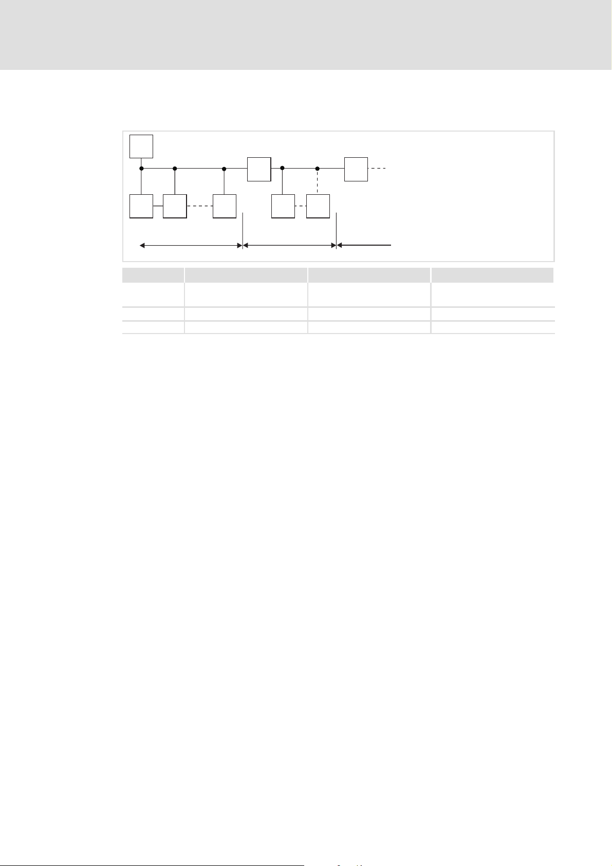
Structure of a PROFIBUS-DP network with RS485 cabling without repeater
1
333
931M
931W
222
1200 m
0m
No. Element Note
1 Master computer e.g. PC or PLC with PROFIBUS-DP master interface module
2 Bus cable Adapt baud rate to the length of the bus cable.
3 PROFIBUS-DP slave Applicable basic device
931M
931W
931M
931W
931m_021
Note!
When using a repeater, max. 125 stations can communicate via the PROFIBUS.
EMC-compliant wiring
For wiring according to EMC please observe the following points:
Note!
ƒ Separate control cables from motor cables.
ƒ Connect the shields of the control or data cables as follows:
– On both sides for cables with digital signals.
ƒ Further notes on wiring according to EMC can be obtained from the
instructions of the basic unit.
Wiring procedure
1. Do not change the bus topology, i.e. do not use stubs.
2. Observe the wiring notes given in the documentation for the control system.
3. Only use cables which correspond to the listed specifications.
4. Activate the bus terminating resistors at the first and last physical station.
14
K-HB 13.0001-EN 2.1
Page 15
Electrical installation 4
Number of bus stations
M
RR
SS S S S
123
Segment Master (M) Slave (S) Repeater (R)
1 1
2
2 - 30 1
3 - 30 1
31
30
-
-
2133PFB004
Tip!
Repeaters do not have a station address but in the calculation of the number
of stations they reduce the number of stations by 1 on each side of the
segment.
Repeaters can be used to build up line and tree topologies. In this case, the
maximum total bus system expansion depends on
ƒ the baud rate used
ƒ the number of repeaters used
K-HB 13.0001-EN 2.1
15
Page 16

Electrical installation4
Baud rate / length of the bus cable
Baud rate [kbit/s] Length [m]
9.6 - 93.75 1200
187.5 1000
500 400
1500 200
Note!
The baud rate, depending on data volume, cycle time, and number of stations,
should be only as high as required for the application.
Tip!
For high baud rates we recommend to check the use of optical fibres.
Advantages of the optical fibre:
ƒ External electromagnetic interferences have no effects on the transmission
path.
ƒ Bus lengths of several kilometres are also possible with higher baud rates.
The bus length
– does not depend on the baud rate.
– depend on the optical fibre used.
Specification of the transmission cable
Please observe our recommendations for signal cables.
Bus cable specification
Cable resistance 135 - 165 Ω/km,(f=3-20MHz)
Capacitance per unit length ≤ 30 nF/km
Loop resistance < 110 Ω/km
Wire diameter >0.64mm
Wire cross-section >0.34mm
Wires double twisted, insulated and shielded
2
16
K-HB 13.0001-EN 2.1
Page 17

Electrical installation
Electrical connection of the servo inverter with the PROFIBUS master
4.1 Electrical connection of the servo inverter with the PROFIBUS master
To meet the requirements of the enclosure IP 54, the servo inverter is equipped with screw
connectors with M12 threads.
The connection plan and assignment of the power connector of the devices can be
obtained from the Operating Instructions 931 M / W.
The following shows the assignment of a 9-pole Sub-D socket the most PROFIBUS masters
are equipped with for connecting field devices.
Connection of the PROFIBUS to 9-pole SubD socket
View Pin Designation Explanation
1
2
3
4
5
Tab. 2 Sub-D connection PROFIBUS
1 free —
6
2 free —
7
3 RxD/TxD-P Data line B (Receive / transmit data plus)
8
4 RTS Request To Send (receive / transmit data, no differential signal)
9
5 M5V2 Data ground (5 V)
6 P5V2 DC5V/30mA(bustermination)
7 free —
8 RxD/TxD-N Data line-A (receive / transmit data minus)
9 free —
4
K-HB 13.0001-EN 2.1
17
Page 18
5
Commissioning
Before switching on
5 Commissioning
5.1 Before switching on
Stop!
Before you switch on the basic unit for the first time in the PROFIBUS-DP
network, check
ƒ the entire wiring for completeness, short circuit, and earth fault.
ƒ whether the bus system is terminated at the first and last station with the
integrated active bus terminating resistor.
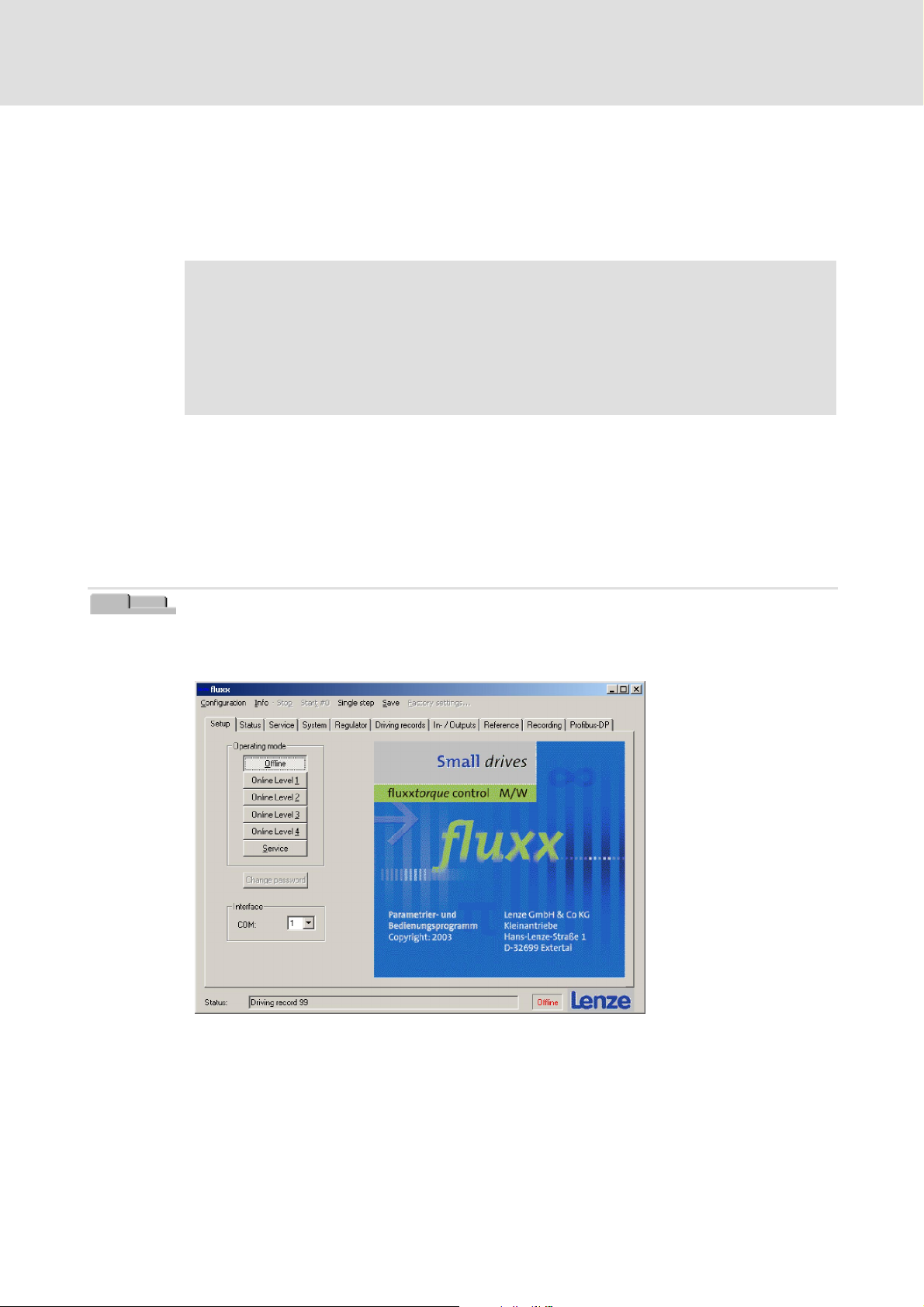
5.2 Activation of PROFIBUS at the servo inverter
Before operating on the PROFIBUS the configurationis carried out via the user interface of
the system. If you are not familiar with the user interface, you will find a detailed
description in the corresponding documentation (see Software Manual 931 M/W).
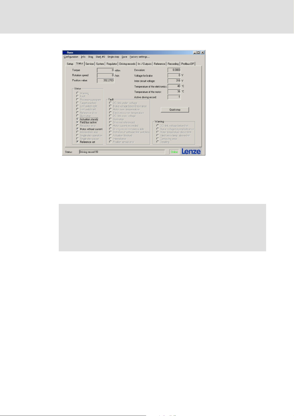
pÉíìé
Start the operating program and check the settings of the serial communicationinterface
in the Setup menu. The servo inverters are set by default to a baud rate of 1.5 MBaud.
931mPro_001
18
K-HB 13.0001-EN 2.1
Page 19
Commissioning
Activation of PROFIBUS at the servo inverter
The Lenze standard RS232connecting cable is plugged in between theinverter (M8 circular
connector, 3-pole) and the COM interface of the PC (Sub-D connector 9-pole). The settings
oftheCOMinterfacemustbecheckedinthehardwaresettingsofthePC.
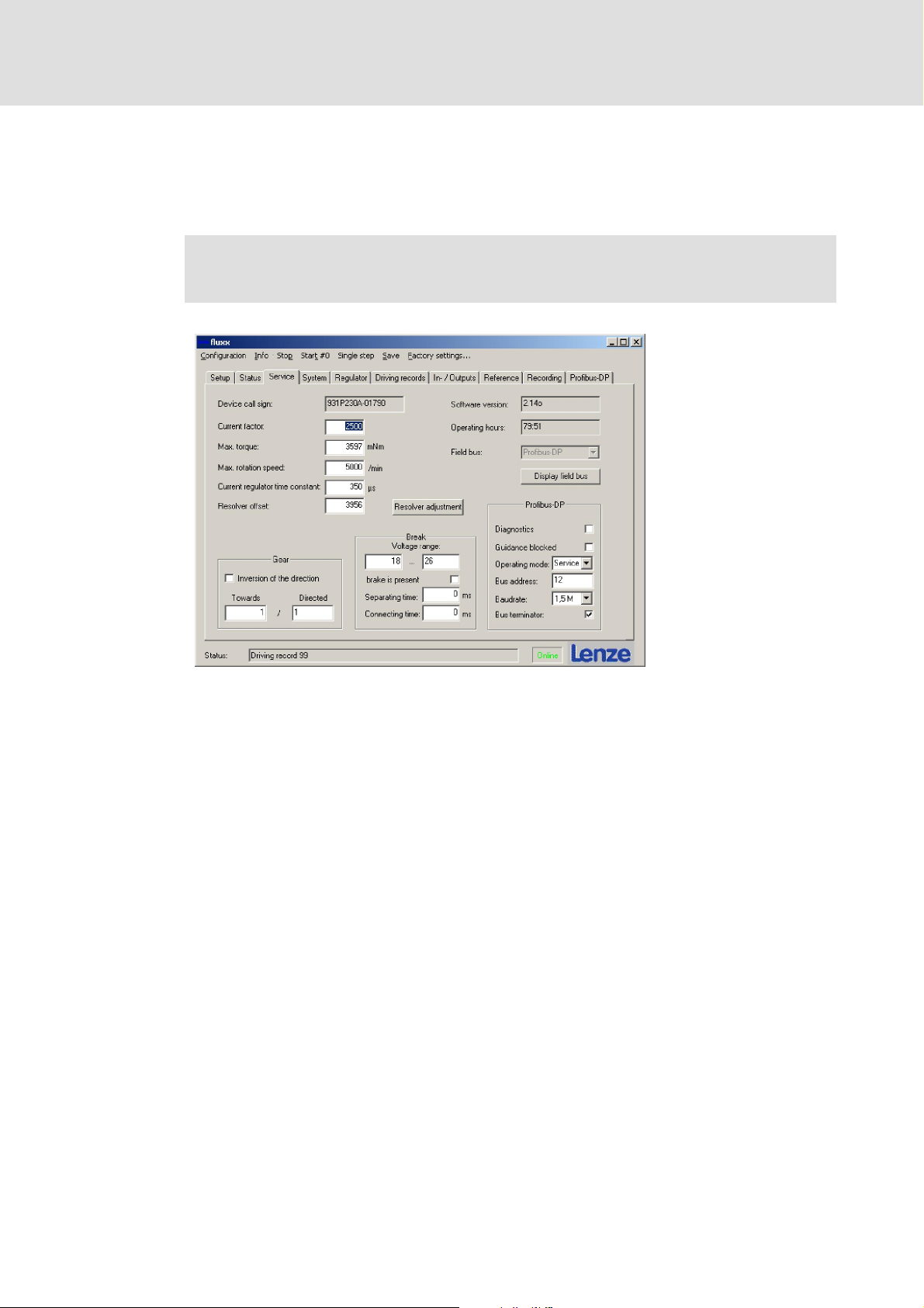
Note!
Select from the Setup menu Online Level 4 or Service.
5
931mPro_002
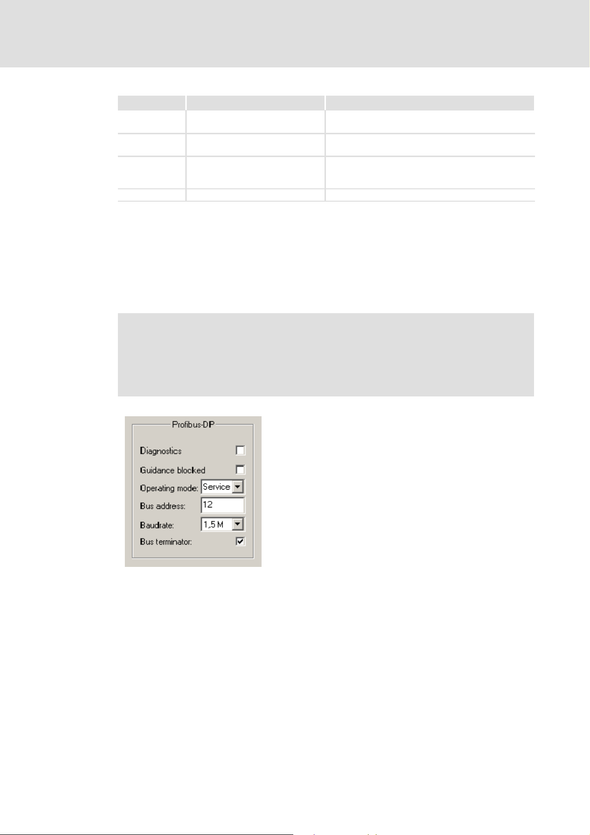
When the Diagnostics function is activated, the diagnostic alarm is switched on. As soon
as a diagnostic alarmis triggered, thedrive automatically sends 4 bytes of diagnostic data
and its start address to thecontrol. Thisserves to obtain information about ifand when an
error occurred in the servo inverter and the data in the control can be evaluated.
TheGuidance blocked servesto exclude thePROFIBUS masterfrom the access to the drive.
As soon as the PROFIBUS master requests the control authority via the drive, the drive can
onlybe startedvia thebus system(intheStatus tab the message”Fieldbus active” appears
in the status field)
K-HB 13.0001-EN 2.1
19
Page 20
5
Commissioning
Activation of PROFIBUS at the servo inverter
931mPro_003
This prevents a simultaneous access to the bus system and the operating program.
The access authorisations of the control to the inverter can be set via the operating mode
on the Setup tab. Restrictions of the access depth like before the access on the inverterby
the operating program are carried out. See Software Manual ”Access authorisations via
access levels.
Note!
ƒ In order that the PROFIBUS master has full access to the inverter (slave),
select the Service operating mode. In this mode, the process and parameter
data can be changed.
ƒ For the parameter setting of the inverter, select from the Setup tab Online
Level 4 or Service.
20
K-HB 13.0001-EN 2.1
Page 21
Commissioning
Activation of PROFIBUS at the servo inverter
Operating mode Access Restrictions
Online level 1 Observing the drive No write access, no change of parameters or process
Online level 3 Access to process data. (Setpoint
selection)
Online level 4 Access to process data and
parameter data (controller settings,
bus settings)
Service Full access No restriction
Tab. 3 Operating modes
Inthe lowerpart of theServicetab, inthe PROFIBUS-DP field,thePROFIBUSaddressandthe
baud rate can be set. Possible are baud rates of 9.6k (k = Kilobyte / 124 bytes) , 19.2k,
93.75k, 187.5k, 500k, 1.5M (M = Megabyte).
In case of the servoinverters, thebus system can belooped through.The devices have a bus
input (X4.1) and a bus output (X4.2). Ifa device shall be connected to theend of the bus line,
a terminating resistor can be activated.
data possible.
No access to parameter data (controller settings, bus
settings, basic drive configuration)
No access to basic drive settings (maximum speed,
maximum torque, …)
5
Note!
To prevent reflections of the signals, the last node must be equipped with a
terminating resistor.
In the Service tab, the checkmark must be set after ”Bus terminator” and
activated via ”Save” in the menu bar.
931mPro_005
K-HB 13.0001-EN 2.1
21
Page 22
5
5.3 PROFIBUS settings in the operating program
Commissioning
PROFIBUS settings in the operating program
mкзСбДмл am
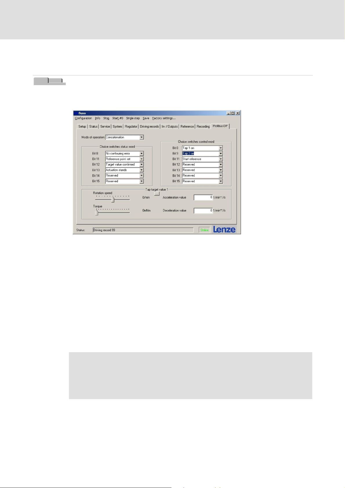
In the operating program, yet further settings can be made for the PROFIBUS operation in
the PROFIBUS-DP tab.
931mPro_004
In caseof an access authorisation higher thanlevel 3,settings can be made here which can
also be executed directly via PROFIBUS. To make access easier for the users, this tab is
inserted. After saving via PROFIBUS and re-reading the travel data records,the settings can
be displayed.
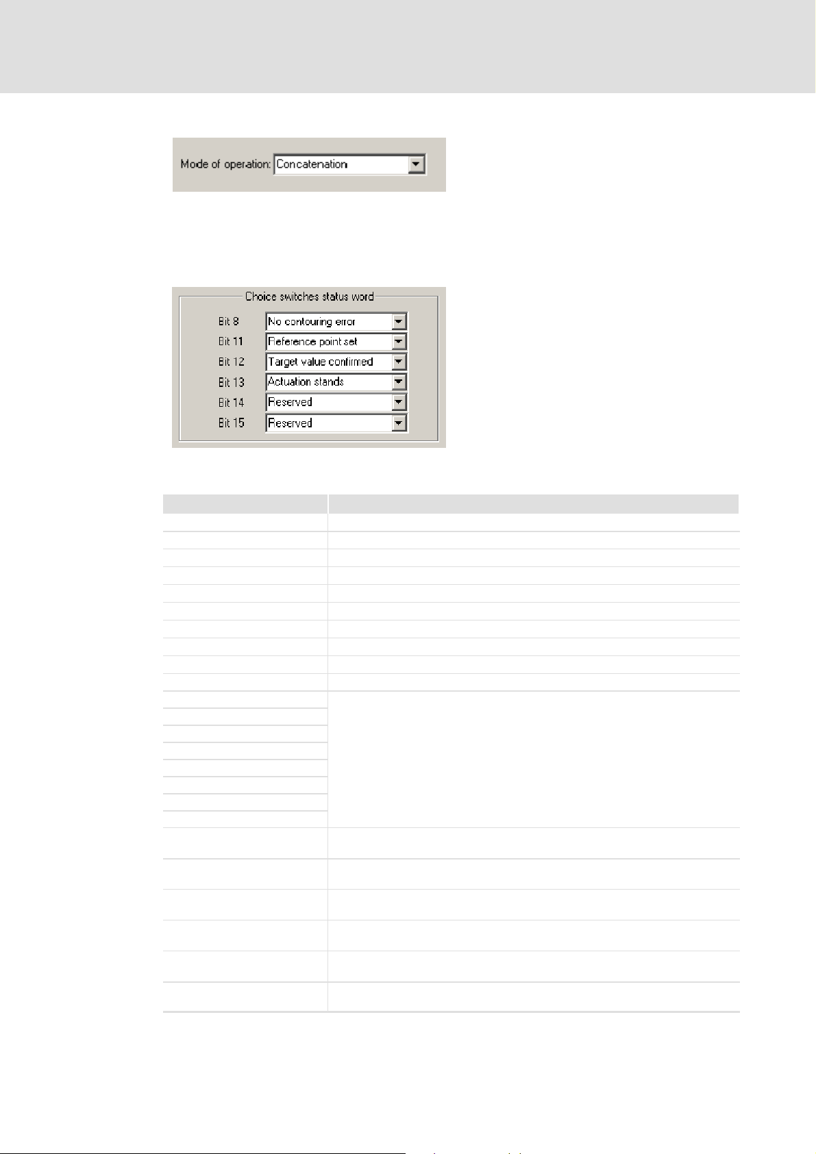
In the upper left of the operating program in the Operating mode field the following
control modes can be selected. You can change-over between the following modes:
ƒ Speed + position
ƒ Speed
ƒ Position
ƒ Concatenation (following error operation / speed control)
This change-over has the same effect as using the parameter number 930 (PNU930).
Note!
If a series of travel data records is to be started via the PROFIBUS which is
written into the drive via the operating program, the concatenation mode
must be selected. In the other operating modes, no series of travel data records
is executed. The drive only carries out single-step operation!
22
K-HB 13.0001-EN 2.1
Page 23
Commissioning
PROFIBUS settings in the operating program
931mPro_006
The operating program also offers the option to display further binary drive data in the
status word.. The bits 8, 11, 12, 13 and 14 can be assigned with other functions than set by
default.
5
931mPro_007
The following display functions listed in the table are available:
Function Description
Brake engaged Brake is applied
Limit switch, left Left limit switch is activated
Limit switch, right Right limit switch is activated
Quick stop Quick stop has been initiated
Reference switch The reference switch is activated
Reference window
Edit data record Data record is being edited / control is active
Digital output Display output of a device with I/O option
Application box output Display application box output of a device with Local CAN option
Digital input Display input of a device with I/O option
Application box 1-BCD
Application box 2-BCD
Application box 4-BCD
Application box 8-BCD
Application box 10-BCD
Application box 20-BCD
Application box 40-BCD
Application box 80-BCD
Application box start Display application box start of a device with Local CAN option (see description
Application box stop Display application box stop of a device with Local CAN option (see description
Application box - left limit
switch
Application box - right limit
switch
Application box - quick stop Display application box quick stop of a device with Local CAN option
Application box input Display application box of a device with Local CAN option (see description of
Tab. 4 Additional functions - status word
Display application box of a device with Local CAN option (see description of
application box)
of application box)
of application box)
Address left application box limit switch of a device with Local CAN option
(see description of application box)
Display right application box limit switch of a device with Local CAN option
(see description of application box)
(see description of application box)
application box)
K-HB 13.0001-EN 2.1
23
Page 24
5
Commissioning
PROFIBUS settings in the operating program
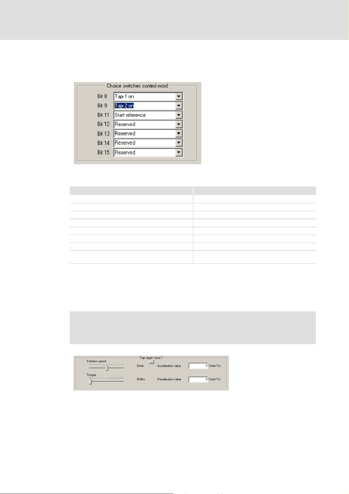
In addition to the display functions, it is possible to set other actions in the control word
which can be addressed.
931mPro_008
The functions are as follows:
Function Description
Engage brake Trigger brake
Activate left limit switch Activate left limit switch
Activate right limit switch Activate right limit switch
Quick stop Activate quick stop
Activate reference switch Activate reference switch
Activate reference window Activate reference window
Activate digital output Activate output of a device with I/O option
Activate application box output Activate application box output of a device with Local
Tab. 5 Additional functions - control word
CAN option.
In the lower part of the PROFIBUS DP field values for the jogging mode can be entered.
Speed, torque, acceleration valueand deceleration value for both joggingsetpoints can be
entered for thejogging mode, which is designed as a mechanical setting-up operation. The
change-over between jogging setpoint 1 and jogging setpoint 2 is done via the field ” ...”.
Danger!
In the jogging mode it is possible to traverse beyond the mechanical limit
switches! The software limit switches are active.
931mPro_009
24
K-HB 13.0001-EN 2.1
Page 25

5.4 PROFIBUS communication
5.4.1 GSE file for PROFIBUS connection
The device data base file (GSE) for DP slaves (e.g. servo inverter of type 931) contains
characteristic device features of the DP components. Here, it is stored, for instance, which
baud rates and special DP modes are supported by the slave.
Each master needs the corresponding device data base file for a non-ambiguous
identification of slaves on the bus. The GSE file for the servo inverters of the Fluxxtorque
series is attached in the appendix and can also be downloaded from www.Lenze.com.
5.4.2 Hardware configuration
Steps for installing the hardware in the PROFIBUS project:
ƒ Install the GSE file ”93MW058F.GSE” (version 1.0) according to the settings of the
project planning software for the DP master. After the installation is completed, the
”931_M_W” device appears among the slave nodes.
Commissioning
PROFIBUS communication
GSE file for PROFIBUS connection
5
ƒ Insert the fieldbus interface module into the PROFIBUS structure using the name
”931_M_W” and assign the PROFIBUS address.
ƒ Select the process data configuration required for your application ( 26).
ƒ Indicate the I/O address for the projected data widths.
ƒ Save the configuration.
ƒ Expand your user program by the data exchange with the servo inverter.
ƒ After the project is saved and loaded into the DP master (e.g. an S7 control of the Fa.
Siemens) and the DP master is started, the LED ”Bus-F” of the MFP/MQP should go
off. If not, check the wiring and terminating resistors of the PROFIBUS as well as the
project planning, especially the PROFIBUS address.
K-HB 13.0001-EN 2.1
25
Page 26

5
Commissioning
PROFIBUS communication
Structure of communication channel
5.4.3 Structure of communication channel
Generally, only communication functions can beset under theHW configurationwhich are
also supported by the servo inverter. The bandwidth of this communication is defined via
the process data configuration. The parameter process data objects (PPOs) serve to select
a pre-defined write and read access to the control and status word by certain ”modules”.
Depending on the selected PPO a certain number of input and output areas, or combined
input and output areas are available. Furthermore, the area selection also determines the
consistency check, data length, and the unit of the data to be transmitted.
PPOs which are sent to the slave by themaster are interpreted as output data (Write-PPO).
Master -> data -> slave: Output data.
PPOs which are received by the master from the slave are interpreted as input data
(Read-PPO). Slave -> data -> master: Input data.
Four different module combinations (PPOs) are available for the process data
configuration:
PPO type 3 PPO Write type
Process data input (input data)
PZD1: Status word X X X X
PZD2: Active travel data record X X X X
PZD3: S p eed — X — X
PZD4: Torque — X — X
PZD5 ... 6: Position — X — X
Process data output (output data)
PZD1: Control word X X X X
PZD2: Actual value = active travel
data record
Parameter data input (input data/PPO
Read)
Number — 2 2 6
Parameter data output (output data/PPO
Write)
Number — — 2 2
Tab. 6 Configuration of the PPO types
X X X X
3 PPO Read type
4
PPO type 1 PPO Write type
1 PPO Read type
2
The configurations ”PPO Write type 3, PPO Read type 4“ and ”PPO type 3” cannot be used
for parameterising the drive. These configurations, however, only provide a lower
utilisation of the bus system, which means a lower data volume. They transmit 16 bytes
less data (8 bytes transmitted data and 8 bytes received data) per telegram than the PPOs
3and4.
Note!
In case of some PROFIBUS master systems HIGH and LOW byte of the process
data and parameter data channel are exchanged!
26
K-HB 13.0001-EN 2.1
Page 27

Control word / status word
General information
6 Control word and status word (Profidrive state machine)
6.1 General information
The servo inverter is controlled via two different access types:
1. The parameters of the inverter are accessed via the acyclic parameter channel
DP-V1. This serves to adapt, change, or set e.g., the controller settings or the driving
records. ( 41).
2. The state of the drive is changed via the state machine. The control word (STW) and
the status word (ZSW) are especially important here. The control word, which is sent
as process data cyclically from the PROFIBUS master (e.g. of a control) to the servo
inverter, changes the state of the drive. This change is detected and confirmed by
the status word which is transmitted from the servo inverter to the master. A
master control can use this information on the drive status to manage the servo
drive.
6
According to the Profidrive profile 2 control words (STW1 and STW2) and 2 status words
(ZSW1 and ZSW2), the single bits of which are defined in this standard with regard to their
meaning, to control the drive. Regarding the control, only the control word 1 (STW1) and
status word 1 (ZSW1) are important for the 931M/W servo inverter. For this reason, only
control and status word 1 will be explained in the following, leaving out the figure ”1” in
the description.
The next three subchapters describe in detail the structure of the control and status word
as well as the state machine and status changes. The change of parameters via the
parameter channel will be explained in the chapter ”Parameter channel” ( 41).
K-HB 13.0001-EN 2.1
27
Page 28

6
6.2 Control word
Control word / status word
Control word
The meaning of the single bits of the control word partly depends on the control selected.
Two control types, speed and positioning control, are available (concerning this see the
parameter PNU 930). In theTab. 7 those bits of the control word are explainedthe meaning
of which are firmly defined irrespective of the controller type. The Tab. 8 and Tab. 9
describe the bits with a controller type-specific meaning. The Tab. 8 contains a detailed
description of the bits for a speed-controlled system and the Tab. 9 describes a
position-controlled system.
To address the inverter via the PROFIBUS master, first the control authority must be
requested bysetting the bit 10 in the control word. Without the control authority thedrive
cannot be accessed. The control authority enables the user to e.g. to start and stop a drive
via the control word or the state machine. ( 33). The user cannot change parameters
with the control authority(e.g. driving records or controlparameters). For this purpose, the
parameter change rights must be requested, see PNU 927 ( 52). The following chapters
describe indetail the connection between thecontrol authority andthe parameter change
rights.
28
K-HB 13.0001-EN 2.1
Page 29

Control word / status word
Bit Value Significance Meaning
0
1
ON Condition for the S3 status ”Ready for operation”: In this status the output
0 OFF 1 Switched-off status: The drive returns to S2 status ”Ready to switch on”.
1
1 No OFF 2 No coasting of the drive is requested.
0 OFF 2
(coasting of the
drive)
2
1 No OFF 3 No quick stop of the drive is requested.
0 OFF 3
(quick stop)
3
1 Enable operation The pulses for the output stage are switched on and the drive changes to
0 Disable operation The drive is braked along the set deceleration ramp to 0 min-1.Afterthat,
7
1 Acknowledging error
(0 → 1)
0
10
1 Control via PLC
(requesting control
authority)
0 No control via PLC No control authority via the drive. Drive status cannot be influenced by
12-15 Device-specific These device-specific bits are not used.
Tab. 7 Overview of the non-controller-type specific bits of the control word
stage is supplied with voltage but not yet connected through (no voltage
at the motor).
When the drive is switched on it is braked along a ramp to zero speed.
When the drive is at standstill, the output stage will be switched off.
Coasting of the drive: The output stage is switched off and the motor
coasts without control to zero speed. After that, the drive changes to the
S1 status ”Switch-on inhibit”.
Quick stop: The drive is braked with maximum power to 0 min-1.Aquick
stop command cannot be cancelled once it has been issued. After quick
stop is terminated, the drive changes to the S1 status ”Switch-on inhibit”.
S4 status ”Operation enabled”. A voltage is applied to the motor
terminals. If a setpoint has been accepted before (see bit 6 STW), this
setpoint is approached.
the drive changes to S3 status ”Ready for operation”.
An error is acknowledged by a positive edge (0→1) on bit 7. The response
of the drive depends on the severity of the error. In case of fatal errors the
drive changes to S1 status ”Switch-on inhibit”.
Requesting control authority: When a control authority is requested, the
status can be changed by a PLC via the PROFIBUS.
the PLC.
6
Control word
K-HB 13.0001-EN 2.1
29
Page 30

6
Control word / status word
Control word
Bit Value Significance Meaning
4
1
Switched-on ramp
generator
0 Reset of the ramp
generator
5
1 Standard ramp
generator
0 Freezing of the ramp
generator
6
1 Accept the setpoint The setpoint which is defined via the current driving record is accepted
0 Do not accept the
setpoint
8
1 JOG1 on Jogging: If JOG1 is switched on from the S4 status ”Operation enabled”,
0 JOG1 off No jogging: If a jogging mode is running it will be terminated. The drive is
9
1 JOG2 on Jogging: If JOG1 is switched on from the S4 status ”Operation enabled”,
0 JOG2 off No jogging: If a jogging mode is running it will be terminated. The drive is
11 Device-specific This device-specific bit is not used.
Tab. 8 Overview of the controller-type specific bit of the control word for a speed-controlled drive
The ramp generator which prevents an abrupt rise of the speed setpoint is
active.
The output of the ramp generator is set to 0 min-1. The drive brakes
considering the current limitation.
No impact (standard function of the ramp generator)
The current setpoint of the ramp generator is ”frozen”.
and transmitted to the ramp function generator.
The setpoint for the ramp function generator is set to 0.
the drive (JOG setpoint selection: see XXX) runs until JOG1 is switched off.
braked to standstill along the deceleration ramp. Afterwards the drive
changes to the S4 status ”Operation enabled”.
the drive (JOG setpoint selection: see XXX) runs until JOG1 is switched off.
braked to standstill along the deceleration ramp. Afterwards the drive
changes to the S4 status ”Operation enabled”.
Bit Value Significance Meaning
4
1
Do not reject the
setpoint
0 Reject the setpoint The drive is braked with maximum acceleration ? to zero speed and
5
1 No intermediate
stop
0 Intermediate stop The drive is braked to zero speed from the active positioning along the
6 Accept the setpoint
(Edge, 0 → 1or
1 → 0)
8
1 JOG1 on Jogging: If JOG1 is switched on from the S4 status ”Operation enabled”,
0 JOG1 off No jogging: If a jogging mode is running it will be terminated. The drive is
9
1 JOG2 on Jogging: If JOG1 is switched on from the S4 status ”Operation enabled”,
0 JOG2 off No jogging: If a jogging mode is running it will be terminated. The drive is
11 Device-specific This device-specific bit is not used.
Tab. 9 Overview of the controller-type specific bit of the control word f or a position-controlled drive
The selected setpoint which is accepted with an edge of bit 6 is
approached.
remains on this position.
No intermediate stop is made. The selected setpoint which is accepted
with the edge of bit 6 is approached.
deceleration ramp. The standstill position is held with a holding torque. By
resetting bit 5 the running positioning is continued.
An edge serves to accept or start a new positioning job or setpoint. A new
setpoint shall only be accepted if a homing process (bit 1 of the status
word) and the previous driving request (bit 12 of the status word) have
been terminated before.
the drive (JOG setpoint selection: see XXX) runs in a speed-controlled
mode until JOG1 is switched off.
braked to standstill along the deceleration ramp. Afterwards the drive
changes to the S4 status ”Operation enabled”.
the drive (JOG setpoint selection: see XXX) runs in a speed-controlled
mode until JOG1 is switched off.
braked to standstill along the deceleration ramp. Afterwards the drive
changes to the S4 status ”Operation enabled”.
30
K-HB 13.0001-EN 2.1
Page 31

6.3 The status word (ZSW)
The current status of the drive is output in the status word and made available to the
master control or PLC. By analogy with the explanation of the control word, first the
meanings of the controller type independent bits of the status word are explained in
Tab. 10. Then the bits with the controller type-specific meaning are explained in Tab. 11
(speed control) and Tab. 12 (position control).
Bit Value Significance Meaning
0
1
Ready to switch on Device is power-supplied, electronics is initialised. Pulses for power section
0 Not ready to switchonDrive is in the S1 status ”Switch-on inhibit”.
1
1 Ready for operation The drive is ready for operation (status S2). In this status, the output stage
0 Not ready for
operation
2
1 Operation enabled The drive is in S4 status ”Operation enabled”. The current setpoint is
0 Operation not
enabled
3
1 Error is pending A non-acknowledged error (see bit 7 of the control word) or an error that
0 No error No error is currently pending.
4
1 Coasting function is
deactivated (no
OFF 2)
0 Coasting function is
active (OFF 2)
5
1 Quick stop function
is deactivated (no
OFF 3)
0 Quick stop function
is active (OFF 3)
6
1 Switch-on inhibit The drive can only change from the S1 state ”Switch-on inhibit” to the S2
0 No switch-on inhibit The drive is in a higher status than S1 ”Switch-on inhibit”.
7
1 Warning is active A warning is pending. The warning does not need to be acknowledged.
0 No warning No warning is pending.
9
1 Control authority is
required
0 Control authority is
not required
14-15 Device-specific These device-specific bits are not used.
Tab. 10 Overview of the non-controller-type specific bits of the status word (ZSW)
Control word / status word
The status word (ZSW)
are suppressed.
is supplied with voltage but not yet enabled (see bit 0 of the control word).
The device is not ready for operation.
processed (see bit 3 of the control word).
Either the pulses are switched off (no voltage at the motor) or the drive
does not follow the setpoint.
cannot be acknowledged is pending at the drive. The response of the drive
is error and device-specific. In case of a fatal error it is changed to status S1
”Switch-on inhibit”. The error can - if the cause has been removed - be
cancelled by an acknowledgement.
The coasting function (see bit 1 ”OFF 2” of the control word) is not active
(bit1STW=1).
The coasting function (see bit 1 ”OFF 2” of the control word) is active (bit 1
STW = 0).
The quick stop function (see bit 2 ”OFF 3” of the control word) is not active
(bit2STW=1).
The quick stop function (see bit 2 ”OFF 3” of the control word) is active (bit
2STW=0).
state ”Ready to switch on” by changing the control word (no OFF2 (bit 1
STW) and no OFF3 (bit 2 STW) followed by ON (bit 0 STW)). After that the
bit 6 of the ZSW returns to 0 (no switch-on inhibit).
The control authority is required for the control (PLC) communicating via
PROFIBUS (see bit 10 of the control word). The drive can be commissioned
via the PROFIBUS.
The drive cannot be controlled via the control (PROFIBUS). Either the
control authority must be requested (see bit 10 of the control word) or the
drivemustbecommissionedviaanotherinterface(seeparameterisation
software Fluxx).
6
K-HB 13.0001-EN 2.1
31
Page 32

6
Control word / status word
The status word (ZSW)
Bit Value Significance Meaning
8
1
Setpoint inside a
tolerance margin
0 Setpoint outside the
tolerance margin
10
1 Setpoint reached The setpoint speed (n) or setpoint frequency (f) has been reached.
0 Setpoint not reached The setpoint speed (n) or setpoint frequency (f) has not been reached.
11-13 Device-specific These device-specific bits are not used.
Tab. 11 Overview of the controller-type specific bit of the status word for a speed-controlled drive
Bit Value Significance Meaning
8
1
Following errors
inside the following
error window
0 Following errors
outside the
following error
window
10
1 Target position
reached
0 Target position not
reached
11
1 Reference set Homing has been executed and a home position has been set.
0 Reference has not
been set
12 Edge for setpoint
13
Tab. 12 Overview of the controller type-specific bits of the status word for a position-controlled drive.
acceptance (0 → 1,
1 → 0)
1 Drive in standstill Thedrivestandsduetoastop/intermediatestoporbecausethetarget
0 Drive is moving Positioning is carried out (n ≠ 0min-1).
The setpoint is inside a required tolerance margin.
The setpoint is outside the required tolerance margin.
The following error is inside the required following error window.
The following error is outside the required following error window.
The current position corresponds to the position setpoint, considering the
position window.
Position setpoint and actual value do not correspond, considering the
position window.
No valid home position exists.
An edge of this bit indicates that a new setpoint / driving record has been
accepted (see bit 6 of the control word)
position has been reached.
32
K-HB 13.0001-EN 2.1
Page 33

State machine and general state diagram
6.4 The Profidrive state machine
6.4.1 State machine and general state diagram
The status of the drive can be changed via the state machine. The single state transitions
are carried out depending on the control word or error management. Basically, the
following states exist according to the Profidrive profile:
ƒ S1: Switch-on inhibit
ƒ S2: Ready to switch on
ƒ S3: Ready for operation
ƒ S4: Operation enabled
ƒ S5: Switching-off/braking
In addition to these states the following substates can be defined which permit a further
concretion of the states mentioned above.
Control word / status word
TheProfidrivestatemachine
6
ƒ Not ready to switch on (initialisation phase of the inverter)
ƒ Fault (drive stands due to an error, acknowledgement is required)
ƒ Fault reaction is active (braking process is active due to an error)
ƒ Quick stop is active
The controland positioning processestake place inthe S4 status (”Operation enabled”).To
reach this status, the other single states must be passed before by changing the
corresponding bits of the control word.
Note!
To change states, the control authority is required (see bit 10 of the control
word)!
Fig. 1 shows the state machine in theform ofa statediagram. To provide a better overview,
only the main states from S1 to S5 are represented. For the sake of simplicity, the state
transitions marked by arrows are provided with the required changes of the bits of the
control word.
K-HB 13.0001-EN 2.1
33
Page 34

6
Control word / status word
TheProfidrivestatemachine
State machine and general state diagram
Bit 1 = 0: No Off2 = 0
Bit 2 = 0: No Off3 = 0
Bit 1 = 0: No Off2 = 0
Bit 2 = 0: No Off3 = 0
Bit 0 = 0: No Off2=0
Switch-on
of power
supply
S1:
Switch-on
inhibit
Bit 0 = 0: ON = 0
Ready to
switch on
Bit 0 = 1: ON = 1 Bit 0 = 0: ON = 0
Ready for
operation
Bit 3 = 1:
Enable Operation = 1
Operation
enabled
Bit 0 = 0: On = 0
Bit 1 = 0: No Off2 = 0
Bit 2 = 0: No Off3 = 0
S2:
S3:
Bit 3 = 0:
Enable Op eration = 0
S4:
At standstill or
Bit 3 = 0, Enable Operation = 0
Bit 0 = 0: ON = 0
At standstill or
Bit 3 = 0, Enable Operation = 0
Braking along
Bit 0 = 1: ON = 1
Fig. 1 General representation of the state diagram
Bit 1 = 0: No Off2 = 0
Bit 1 = 0:
No Off2 = 0
S5: Switching-off
Quick stop:
ramp
Bit 2 = 0: No Off3 = 0 (Quick s top)
Braking along
Bit 2 = 0:
ramp
931m_022
The current status of the drive can be obtained from the status word (ZSW) of the drive. In
the Tab. 13 the single bits of the status word and the states are listed.
34
K-HB 13.0001-EN 2.1
Page 35

Control word / status word
TheProfidrivestatemachine
State machine and general state diagram
6
Status
S1 switch-on inhibit 1 X 0 0 0 0
S2 ready to switch on 0 1 0 0 0 1
S3 ready for operation 0 1 0 0 1 1
S4 operation enabled 0 1 0 1 1 1
S5 switch-off 0 X X 1 1 1
Not ready to switch on 0 X 0 0 0 0
Fault 0 X 1 0 0 0
Fault response is active 0 X 1 1 1 1
Quick stop is active 0 0 0 1 1 1
Tab. 13 Confrontation of the states of the device and the status word (ZSW) in bit format
Bit 6 Bit 5 Bit 3 Bit 2 Bit 1 Bit 0
Switch-on
inhibit
Quick stop Fault Enable
operation
Ready for
operation
Ready to
switch on
In all states - despite the ”Not ready to switch on” status, which is only pending a short
while after switching on the voltage supply (self-initialisation) - the parameters of the
servo inverters may be reparameterised by the parameter channel ifthe parameterchange
rights (see PNU 927) was requested before. The changes of the control word required for
the status changes are shown in Fig. 1.
Note!
For safety reasons the servo inverter can only be operated from an interface.
This means that the parameter change rights may either be occupied by the
Fluxx operating program or the control (PROFIBUS).
If an operating program with level 2 or higher has been selected at the
inverter, no parameter change rights can be requested via the PROFIBUS. In
this case it is required to change the operating mode of the Fluxx program on
level 1 (monitoring) or offline.
As aforementioned, the real control process takes place in the status S4 ”operation
enabled”. To, e.g. accept a setpoint or start homing, further changes o f the controlword are
required. Since these changes depend on the set control, the state diagrams for a
speed-controlled and a position-controlled system will be described separately.
K-HB 13.0001-EN 2.1
35
Page 36

6
Control word / status word
TheProfidrivestatemachine
Example: State machine for speed operation
6.4.2 Example: State machine for speed operation
In this example, the drive is to be commissioned with the predefined driving record no. 1
(n = 2400 1/min; M = 1320 mNm) with speed control.
The selected PPO type 3 permits the writing and reading of the control word / status word
and the selection of the pre-programmed driving records. The selected PPO type
determines the input and output addresses of the registersto bedescribed (”buffer”)in the
frequency inverter. It is mandatory for the state transitions to write the control words
stepwise; the following table displays the bit patterns for a better understanding:
Status High byte STEW (1. address) Low byte STEW (2. address)
s1 0000 0100 0011 0110
S2 0000 0100 0011 0111
S3 0000 0100 0111 1111
S4 0000 0100 1011 1111
S5 0000 0100 1011 1110
Tab. 14 Control word state transitions - speed example
As aforementioned, it is possible to open a PROFIBUS monitor via the ”Display fieldbus”
field in the ”Service”tab ofthe operatingprogram. The following screenshots illustrate the
single steps of the state machine by means of the PROFIBUS monitor:
Status S1: Switch-on inhibit Status S2: Ready to switch on
931mPro_010 931mPro_011
36
K-HB 13.0001-EN 2.1
Page 37

Control word / status word
TheProfidrivestatemachine
Example: State machine for speed operation
Status S3: Ready for operation Status S4: Operation enabled
931mPro_013 931mPro_012
S5: Switching off / Braking -> identical with S4 except for bit no. 0.
6
K-HB 13.0001-EN 2.1
37
Page 38

6
6.4.3 State diagram for positioning
Control word / status word
TheProfidrivestatemachine
State diagram for positioning
Fig. 2 shows the state machine for aposition-controlled drive in the basic state ”Operation
enabled”.
931m_023
Fig. 2 State machine ins the ”positioning” mode
In this operating status, the following actions can be executed via the control word:
1. Via bit 11 of the STW homing can be started. Bit 11 in the ZSW ”Home position is
set” indicates if a home position is set (valid). If homing is started, the display
”Homing set” (bit 11) is cancelled. The type of homing (direction, speed, etc.) is
application and device-specific and is hence not described in the profile. For this
purpose the parameters required for homing (PNU 101) must be checked before.
2. To accept a new setpoint or change a driving record, the edge of bit 12 of STW
”Setpoint acknowledgement” must be changed. This starts and executes the
positioning mode.
3. Via the function JOG1 and JOG2 (bit 8 and bit 9 of STW) a jogging mode can be
carried out.
38
K-HB 13.0001-EN 2.1
Page 39

Control word / status word
TheProfidrivestatemachine
State diagram for positioning
Stop!
In case of a jogging mode (JOG1 and JOG2) the software and hardware limit
switches are not evaluated!
The drive is not limited with regard to its permitted travel range!
During the positioning process, several options exist to intervene in the process:
1. A travel request can be interrupted using the command ”Intermediate stop” (bit 5 of
STW). The drive brakes along the set deceleration ramp to standstill. The current job
request is stopped and can be continued by cancelling the command ”Intermediate
stop”.
2. In the ”Intermediate stop” state, homing can be started.
3. A travel request can be cancelled using the command OFF1 (bit 0 of STW: Drive off),
OFF2 (bit 1 of STW: Coasting) or OFF3 (bit 2 of STW: Quick stop). The drives brakes
depending on the mode selected to standstill and then changes to S1 status
”Switch-on inhibit” (OFF2, OFF3) or S2 ”Ready to switch on”.
6
A travel request is terminated when the drive has reached its setpoint. This is displayed
with the status bit 10 ”Setpoint reached”.
The ”Concatenation” mode enablesspeed-controlled and positioning driving recordsto be
started without taking special measures. Here, the following driving records and waiting
times between the concatenated driving records are considered. Further information can
be obtained from the explanation of the object PNU 100.
K-HB 13.0001-EN 2.1
39
Page 40

6
6.4.4 State diagram for speed control
Control word / status word
TheProfidrivestatemachine
State diagram for speed control
Fig. 3 shows the state machinefor aspeed-controlled drive in the basic state S4”Operation
enabled”. Many functions of the illustrations shown are similar to the ones of section
( 38) so that only deviant functions shall be explained here.
40
931m_024
Fig. 3 State machine in the ”speed control” mode
As explained in section ”State diagram for positioning” ( 38),the jogging mode can also
run in speed-controlled operation.
Through an edge of bit 6 of STW a new speed setpoint or driving record is accepted and
executed. The drive can be braked via the functions OFF1, OFF2 and OFF3. ( 38).
K-HB 13.0001-EN 2.1
Page 41

Parameter channel (PCV mechanism)
7 Parameter channel (PCV mechanism)
Certain drive functions are further accessed via the parameter characteristic value (PCV)
mechanism.The PCVmechanism servesto process parameters in cyclicdata exchange.The
PCV mechanism is used to:
ƒ operate and observe parameters (master -> slave).
ƒ transfer spontaneous messages (slave -> master -> slave).
Moreover, it serves to, e.g.:
ƒ set control authority and parameter change rights
ƒ define setpoints
ƒ read out status information
ƒ configure limit switches.
Inthe PCVmechanism, themaster definesa job,the slaveprocesses thejob andformulates
the response. Jobs and responses cannot be blocked. Each PPO-Write contains exactly one
job and each PPO-Read contains exactly one response. Hence, maximally 4 user data bytes
can be transmitted with one job or one response. In the parameter ID, job/response and
the corresponding parameters are coded.
7
Access authorisation
7.1 Access authorisation
Since the parameter characteristic value mechanism (PCV) serves to access setpoints and
parameters, the user should pay attention to the access authorisation. For setpoint
selection, the PROFIBUS master requires the parameter change rights over the servo
inverter. A simultaneous access of the operating program and a PROFIBUS master is
neither possible nor sensible.
In the ”Level 0” operating mode, the operating program can be used to observe the drive.
When commissioning, the current status of the drive can be observed at the same time. If
the operatingprogram is logged onthe servo inverter with an operating mode higher than
”Level 1”, an access conflict occurs and the PROFIBUS master cannot access the drive.
The operating program enables the user to configure the access authorisation of the
PROFIBUS master to the servo inverter, as described in chapter ”Activation of PROFIBUS at
the servo inverter”. ( 18) .
K-HB 13.0001-EN 2.1
41
Page 42

7
Parameter channel (PCV mechanism)
Structure of the parameter characteristic value
Structure of parameter identification (PKE)
7.2 Structure of the parameter characteristic value
When processing the PCV, a job identification, the corresponding PNU (parameter
number) and a value are transmitted. The job identification indicates if data of different
sizes are to be written or requested. The single job identifications are listed in Tab. 19. The
PNUs which arespecified subsequently serve to define the object, the value to be changed
and the access. The PNU number (represented decimally) must be first converted into a
hexadecimal numerical format and can thus be processed directly or entered binary. Then
the basicstructure of the PCV mechanism is shown.The procedure is to be explained using
an example.
Area Description
Parameter
characteristic
value (PCV)
PKE Parameter number (PNU) and job or response identification
IND Subindex and reserved area
PWE Since the higher-order bits (bits 16 ... 31) are not used, they must be set to ”0”. Lower-order
bits (bits 0 ... 15): Parameter values.
Tab. 15 Abbreviations - PCV mechanism
7.2.1 Structure of parameter identification (PKE)
The following table shows the binary structure of the PCV message:
Bit 15 14 13 12 11 10 9 8 7 6 5 4 3 2 1 0
SPM
Job identification
Tab. 16 Structure of parameter identification
Job identification Job or response identification (value range 0 ... 15)
SPM Toggle bit for spontaneous message processing
PNU Parameter number (value range 1 ... 1999)
7.2.2 Subindex
The subindex serves to ensure, e.g., an assignment to the correct parameter value in an
array
Bit 7 6 5 4 3 2 1 0
Value
Tab. 17 Subindex
Parameter number (PNU)
7.2.3 Parameter value
The values of the individual objects are transmitted with the parameter value.
Byte 7 6 5 4 3 2 1 0
Value
Tab. 18 Parameter value
42
K-HB 13.0001-EN 2.1
Page 43

Parameter channel (PCV mechanism)
7.3 Job and response processing
The job andresponse processing is defined sothat the identification shows which fields of
the PCV interface (IND,PWE) must be evaluated. Moreover, a distinction is made between
parameter value and parameter description.
7.3.1 Job identification (master -> slave)
To change a parameter value the slave must receive a job identification from the master
(see Tab. 19). This job identification depends on the data type or format to be changed
(word, double word, array).
After the slave has received and executed the job successfully, a corresponding response
is generated (see Tab. 20), which also shows transmission errors. The response data is
available at the slave as long as a new job is transmitted.
7
Job and response processing
Job identification (master -> slave)
Job identification Function
0Nojob 0
1 Request parameter value 1, 2 7
2 Change parameter value (word) 1 7, 8
3 Change parameter value (double word) 2 7, 8
4 Request describing element (double word) 3 7
5 Change describing element 3 7, 8
6 Request parameter value (array) 4, 5 7
7 Change parameter value (array word) 4 7, 8
8 Change parameter value (array double word) 5 7, 8
9 Request number of array elements 6 7
Tab. 19 Overview of job identifications
Response identification
Positive Negative
K-HB 13.0001-EN 2.1
43
Page 44

7
Parameter channel (PCV mechanism)
Job and response processing
Response identification (slave -> master)
7.3.2 Response identification (slave -> master)
The response shows if the transmission was successful or if a transmission error occurred.
The response helps to exactly locate the error. The following table contains all responses
to the implemented job identifications.
Note!
If a parameter of the slave in double word format is to be changed, but the job
identification refers to a change of a parameter in word format, the slave
responds with a corresponding error message / number (see Tab. 21).
Response identification Function
0Nojob
1 Transmit parameter value (word)
2 Transmit parameter value (double word)
3 Transmit describing element
4 Transmit describing element (array word)
5 Transmit describing element (array double word)
6 Transmit number of array elements
7 Job cannot be executed (with error number)
8 No parameter change rights for PCV interface
9 Spontaneous message - word
10 Spontaneous message - double word
Tab. 20 Overview of response identifications
If jobs cannot be executed, the slave responds with an error number.
44
K-HB 13.0001-EN 2.1
Page 45

7.3.3 Error numbers at response
Error number Information Detailed description
0 Impermissible PNU The parameter number is not assigned.
1 Parameter value cannot be
changed
2 Loweroruppervaluelimit
exceeded
3 Faulty subindex The indicated subindex of the object does not exist or a
4 No array The addressed object is no array type.
5 Wrong data type The object has been addressed as a wrong data type. See
6 No setting permitted (only
resettable)
7 Describing element cannot be
changed
8 PPO - Write requested in the IR is
not available
9 Description data not available
10 Wrong access group Access error! The PROFIBUS interface has no parameter
11 No parameter change rights Parameter change rights not requested or access not
12 Wrong password A password has been assigned which must be entered for
13 Text in cyclic traffic cannot be
read
14 Name in cyclic traffic cannot be
read
15 No text array available
16 PPO - Write is missing When installing the hardware a wrong data type was
17 Job cannot be executed due to
operating status
18 Other errors
19 ... 100 Date in the cyclic traffic cannot
be read
Tab. 21 Overview of error messages - job identifications
Parameter channel (PCV mechanism)
Job and response processing
Error numbers at response
This is a non-writable object, e.g. an actual value.
Thepermissiblewritablelimitrangeoftheobjecthasbeen
exceeded. Please observe object limits.
format error exists. Check entries.
job identification table.
No setting permitted (only resettable)
Elements such as the serial numbers cannot be changed.
When installing the hardware a wrong data type was
selected. Please check the HW settings.
change rights. See PNU 927.
Possible error: Parameter change rights have not been
requested. The operating program and PROFIBUS master try
to access the drive simultaneously. Wrong software
settings in the operating program. (See activation of
PROFIBUS)
possible.
processing. See password.
selected. Please check the HW settings.
Check operating status. Is an error pending at the drive?
Errorscanbeobservedviathesoftwareintheonlinelevel1
under Status.
7
The error numbers 0 ... 100 are defined or reserved profile-oriented.
K-HB 13.0001-EN 2.1
45
Page 46

7
Parameter channel (PCV mechanism)
Job and response processing
Examples of PCV mechanism
7.3.4 Examples of PCV mechanism
Example 1: Request parameter change rights:
To requestthe parameter change rights a parameter valuemust be transmitted, sothe job
identificationis 2.The PNUnumber is927. Thiscorresponds to39F inthe hexadecimaldata
format. The value 1 is transmitted as parameter value. The parameter value serves to
transmit the control authority to the PROFIBUS master. After this action, the operating
program cannot access the servo inverter anymore.
Parameter identification:
Bit 15 14 13 12 11 10 9 8 7 6 5 4 3 2 1 0
Binary value 0 0 1 0 0 0 1 1 1 0 0 1 1 1 1 1
Hexadecimal value 2 3 9 F
Request parameter
value
Subindex
PNU
Bit 7 6 5 4 3 2 1 0
Binary
value
0 0 0 0 0 0 0 0
Parameter value
Byte 7 6 5 4 3 2 1 0
Value 0000 0000 0000 0000 0000 0000 0000 0001
As response identification the value 1 is output as job identification, see Tab. 20. This
means: Transmission of parameter values.
Response identification :
Bit 15 14 13 12 11 10 9 8 7 6 5 4 3 2 1 0
Binary value 0 0 0 1 0 0 1 1 1 0 0 1 1 1 1 1
Hexadecimal value 1 3 9 F
Transmit parameter
value
PNU
In the subindex, the response contains a zero and in the parameter value of the response
the requested value, in this case 1, is returned.
46
K-HB 13.0001-EN 2.1
Page 47

Parameter channel (PCV mechanism)
Job and response processing
Examples of PCV mechanism
Example 2: Reading the set speed
To read the set maximum speed out of the drive, the parameter is requested from the
inverter.
Here, the parameter identification consists of the value 6 in the job identification for
requesting the parameter value, see Tab. 19, and the driving record number as PNU, e.g.
driving record 1, see chapter data type driving record 1 to 100 ( 61). The subindex
contains the number of the parameter to be requested, see ( 61), subindex 1 for
maximum speed.
Parameter identification:
Bit 15 14 13 12 11 10 9 8 7 6 5 4 3 2 1 0
Binary value 0 1 1 0 0 0 0 0 0 0 0 0 0 0 0 1
Hexadecimal value 6 0 0 1
Request parameter
value
Subindex
PNU
7
Bit 7 6 5 4 3 2 1 0
Binary
value
0 0 0 0 0 0 0 1
Parameter value
Byte 7 6 5 4 3 2 1 0
Value 0000 0000 0000 0000 0000 0000 0000 0000
As response identification a 4 is output as job identification, and the PNU, in this case 001
is output for driving record 1, see Tab. 20. This means: Transmit parameter value (array
word).
Response identification :
Bit 15 14 13 12 11 10 9 8 7 6 5 4 3 2 1 0
Binary value 0 1 0 0 0 0 0 0 0 0 0 0 0 0 0 1
Hexadecimal value 4 0 0 1
Transmit describing
element
PNU
Subindex
Bit 7 6 5 4 3 2 1 0
Binary
value
0 0 0 0 0 0 0 1
Parameter value, e.g. for 6000 1/min
K-HB 13.0001-EN 2.1
Byte 7 6 5 4 3 2 1 0
Value 0000 0000 0000 0000 0001 0111 0111 0000
47
Page 48

7
Parameter channel (PCV mechanism)
Job and response processing
Examples of PCV mechanism
Example 3: Change of the set speed
To change the speed in a driving record, a similar procedure like requesting parameter
values is selected. As job identification, a 7 must be entered here (job identification 7 –
change parameter value).
To continue to let the drive run with a changed speed, the edge at bit 6 of the control word
must be changed for acknowledgement after changing the setpoint. The new setpoint is
accepted after every edge change (0 after 1 and 1 after 0).
Parameter identification:
Bit 15 14 13 12 11 10 9 8 7 6 5 4 3 2 1 0
Binary value 0 1 1 1 0 0 0 0 0 0 0 0 0 0 0 1
Hexadecimal value 7 0 0 1
Change parameter
value
PNU
Subindex
Bit 7 6 5 4 3 2 1 0
Binary
value
0 0 0 0 0 0 0 1
The subindex indicates the parameter to be addressed.
Parameter value
Byte 7 6 5 4 3 2 1 0
Value 0000 0000 0000 0000 0000 0000 0110 0100
In this example, the parameter value is the speed. Here, a value of 100 1/min is selected.
As response identification a 4 is output as job identification, and the PNU, in this case 001
is output for driving record 1, see Tab. 20. This means: Transmit parameter value (array
word).
Response identification :
Bit 15 14 13 12 11 10 9 8 7 6 5 4 3 2 1 0
Binary value 0 1 0 0 0 0 0 0 0 0 0 0 0 0 0 1
Hexadecimal value 4 0 0 1
Transmit describing
element
PNU
Subindex
Bit 7 6 5 4 3 2 1 0
Binary
value
0 0 0 0 0 0 0 1
48
Parameter value, e.g. for 100 1/min
Byte 7 6 5 4 3 2 1 0
Value 0000 0000 0000 0000 0000 0000 0110 0100
K-HB 13.0001-EN 2.1
Page 49

Parameter channel (PCV mechanism)
Job and response processing
Examples of PCV mechanism
Example 4: Reversal
To change the direction of rotation, the subindex 6 of the data type driving record 1 to 100
(PNU 1to 100) is addressed. The table listsas data type the subindex 6 bit[…]. The number
which is listed in parenthesis, corresponds to the bit which must be set to change the
status.The subindex 6 serves to change, e.g. the acceleration ramp form, brake ramp,
controller type, driving direction and direction of rotation. In our example, bit 4 is
addressed to cause a reversal of rotation direction.
Parameter identification:
Bit 15 14 13 12 11 10 9 8 7 6 5 4 3 2 1 0
Binary value 0 1 1 1 0 0 0 0 0 0 0 0 0 0 0 1
Hexadecimal value 7 0 0 1
Change parameter
value
Subindex
Bit 7 6 5 4 3 2 1 0
Binary
value
0 0 0 0 0 1 1 0
PNU
7
The subindex indicates the parameter to be addressed.
Parameter value
Byte 7 6 5 4 3 2 1 0
Value 0000 0000 0000 0000 0000 0000 0001 0000
In this example, the parameter value (Bit 4 =1) reverses the direction of rotation.
As response identification a 4 is output as job identification, and the PNU, in this case 001
is output for driving record 1, see Tab. 20. This means: Transmit parameter value (array
word).
Response identification :
Bit 15 14 13 12 11 10 9 8 7 6 5 4 3 2 1 0
Binary value 0 1 0 0 0 0 0 0 0 0 0 0 0 0 0 1
Hexadecimal value 4 0 0 1
Transmit describing
element
PNU
Subindex
Bit 7 6 5 4 3 2 1 0
Binary
value
0 0 0 0 0 1 1 0
Parameter value like parameter requirement.
To convert the reversal of rotation direction into an action, an edge at bit 6 of the control
word is changed.
K-HB 13.0001-EN 2.1
Byte 7 6 5 4 3 2 1 0
Value 0000 0000 0000 0000 0000 0000 0001 0000
49
Page 50

7
7.3.5 Transfer of PPO with PROFIBUS-DP
Parameter channel (PCV mechanism)
Job and response processing
Transfer of PPO with PROFIBUS-DP
The DP function Data_Exchange
In case of PROFIBUS-DP the cyclic data exchange with PPOs is available only. For this
purpose, DP provides the function Data_Exchange, which serves to transmit cyclic data to
the slave and collect them at the same time. The input or output data exchanged with
Data_Exchange correspond to the PPO types described. However, changing the PPO type
during the operation is not possible.
The DP function Set_Prm
This function serves to transmit 7 bytes of PROFIBUS-DP-specific information to the slave.
The option to transmit device-specific parameters (User_Prm_Data) from byte 8 to 244 is
not used.
The DP function Slave_Diag
This function serves to read 6 bytes of PROFIBUS-DP-specific diagnostic information and
2 further bytes Ext_Diag_Data out of the slave. The Ext_Diag_Data provides a
device-specific diagnostics, in which error messages of the slave are displayed. The output
of the drive-specific diagnostics can be switched off by parameter setting.
Synchronisation of several devices, the DP_function Global Control
The DP function Global Control serves to synchronise several drives. If a master sends a
sync control command, the outputs of the addressed slaves are frozen to the momentary
value. In thefollowing userdata transmissions,the outputdata are stored in theslaves, the
output data remains unchanged. When giving the next sync control command the stored
output dataare transmitted to the outputs. An unsync control command serves to exit the
sync operation.
By analogy with this, the freeze control command enables the input s tates to be frozen to
the momentary value and to be collected with the next user data transmission. The input
data are only updated again, when the DP master transmits the next freeze control
command to the devices concerned. The freeze operation is exited with an unfreeze
control command.
The DP function Set_Slave-Add
This optional function is not implemented.
50
K-HB 13.0001-EN 2.1
Page 51

8 Parameter numbers
Parameter numbers defined in the ”Profidrive” PROFIBUS profile
The parameter numbers 900 to 999 are defined or reserved to profile specifications.
Overview of the parameter numbers defined in the ”Profidrive” PROFIBUS profile.
PNU Meaning Data type
918 Station address Unsigned 16
927 Parameter change rights (PCV) Unsigned 16
928 Control authority (PZD) Unsigned 16
930 Selection for operating mode Unsigned 16
947 Fault number Unsigned 16
970 Load parameters Unsigned 16
971 Transfer into non-volatile memory Unsigned 16
Tab. 22 Profidrive parameter numbers
Parameter numbers
Explanation of the parameter numbers
Node address (PNU 918)
8
8.1 Explanation of the parameter numbers
The single PNUs, their functions and structure are described in the following paragraph:
How to read the tables
Column Meaning
PNU Parameter number
Subindex Subindex
Description Description of the parameter number
Lenze Lenze setting of the parameter number
Selection minimum value [smallest increment/unit] maximum value
Data type z Integer 16
z Unsigned 16
Tab. 23 Explanation of the tables
8.1.1 Node address (PNU 918)
PNU Subindex Description
918
0 Station address
Possible settings
Lenze Selection
2 126
Data type
Unsigned 16
K-HB 13.0001-EN 2.1
Selection Meaning Description
2 ... 126 After the station address has been changed, the PROFIBUS-DP
interface makes a reset in the drive.
51
Page 52

8
Parameter numbers
Explanation of the parameter numbers
Parameter change rights (PNU 927)
8.1.2 Parameter change rights (PNU 927)
PNU Subindex Description
927
0 Parameter change rights (PCV)
Selection Meaning Description
0 No parameter change rights for
the PROFIBUS interface
1 Parameter change rights for the
PROFIBUS interface
8.1.3 Control authority (PNU 928)
Possible settings
Lenze Selection
0 1
This value serves to request the parameter change rights for the
PROFIBUS interface. Two errors may occur:
z The parameter change rights apply for the operating program
(operating mode ≥ ”Online Level 3”), i.e. the operating mode
must be ≤ 2
z The PCV level in the PROFIBUS parameters (PNU106) is set to 0.
If the master w ants to write PCV values without parameter
change rights, an error message occurs.
Data type
Unsigned 16
Possible settings
PNU Subindex Description
928
0 Control authority (PZD)
Selection Meaning Description
0 Control authority for operating
program
1 Control authority for PROFIBUS
interface
2 Control authority for local I/O
Lenze Selection
The control authority is obligatory to activate the state machine of
the drive. It serves to transmit start commands to activate driving
records. The control authority is required to carry out setpoint
selections (see PNU 927).
8.1.4 Selector switch for operating mode (PNU 930)
Possible settings
PNU Subindex Description
930
0 Selector switch for operating
Selection Meaning Description
1 Speed control mode The drive can only be operated speed-controlled in the speed
2 Positioning mode With this configuration, the drive can only execute positioning
0x8000 Concatenation mode The concatenation mode permits speed-controlled and positioning
mode
Lenze Selection
mode. When a driving record is started with ”Positioning” control
type, the drive travels following error-controlled.
driving records. When you try to start a driving record with the
speed control, the fault signal ”Driving record” is displayed.
driving records to be started via a DP master. Here, also following
driving records and waiting times between chained driving records
are considered.
Data type
Unsigned 16
0 2
Data type
Unsigned 16
1 0x8000
52
K-HB 13.0001-EN 2.1
Page 53

Explanation of the parameter numbers
Selector switch - control word bit 8 (PNU 931)
8.1.5 Selector switch - control word bit 8 (PNU 931)
Possible settings
PNU Subindex Description
931
0 Selector switch - control word
Selection Meaning Description
1 Jogging 1 ON / OFF When the drive is ready to start and the control bit 8 is activated,
0x8000 Engage / disengage the brake When the corresponding control word bit is activated which is
0x8001 Left limit switch is active /
0x8002 Right limit switch is active /
0x8003 Quick stop is active / inactive An activated quick stop brakes the motor with the maximum
0x8004 Referenceswitchisactive/
0x8005 Reference window is active /
0x8010 Controller output is active /
0x8020 IO box output is activated /
bit 8
inactive
inactive
inactive
inactive
inactive
deactivated
Lenze Selection
the jogging mode is started with the set jogging setpoints. When
the bit is reset, the jogging process is stopped again.
assigned to the ”Engage brake” function, the brake is closed. This
can happen while a driving record is executed or during position
control back-up time at standstill. During travel the output stage
is switched off simultaneously, at standstill after the engagement
time. After activation, the brake will only be released again, when
the bit is reset and a travel job is activated, or the external signal
”Releasing the brake” is pending. If the bit is set the start of a
travel job will be ignored and not carried out.
These functions permit t he simulation of an activated limit switch
per control software
possible torque to zero speed.
This function serves to simulate an activated limit switch per
control software.
This function is not implemented
The application box output is switched to HIGH level when the
control word bit with the function ”Activate application box
output” is set. Resetting the bit switches the output to LOW level
again.
Parameter numbers
1 0x8020
8
Data type
Unsigned 16
K-HB 13.0001-EN 2.1
53
Page 54

8
Parameter numbers
Explanation of the parameter numbers
Selector switch - control word bit 9 (PNU 932)
8.1.6 Selector switch - control word bit 9 (PNU 932)
Possible settings
PNU Subindex Description
932
0 Selector switch - control word
Selection Meaning Description
1 Jogging 2 ON / OFF When the drive is ready to start and the control bit 8 is activated,
0x8000
...
0x8020
bit 9
See PNU 931
Lenze Selection
the jogging mode is started with the set jogging setpoints. When
the bit is reset, the jogging process is stopped again.
8.1.7 Selector switch - control word bit 11 (PNU 933)
Possible settings
PNU Subindex Description
933
0 Selector switch - control word
bit 11
Lenze Selection
Data type
Unsigned 16
1 0x8020
Data type
Unsigned 16
1 0x8020
Selection Meaning Description
1 Start homing / cancel homing This function serves to start or stop the homing mode via the
0x8000
See PNU 931
...
0x8020
control word bit 11.
8.1.8 Selector switch - control word bit 12 ... 15 (PNU 934 ... 937)
Possible settings
PNU Subindex Description
934
0 Selector switch - control word
...
937
Selection Meaning Description
1 Reserved
0x8000
...
0x8020
Bit 12 ... 15
See PNU 931
Lenze Selection
1 0x8020
Data type
Unsigned 16
54
K-HB 13.0001-EN 2.1
Page 55

Explanation of the parameter numbers
Selector switch - status word bit 8 (PNU 938)
8.1.9 Selector switch - status word bit 8 (PNU 938)
Possible settings
PNU Subindex Description
938
0 Selector switch - status word
Selection Meaning Description
1 No following error / following error If the status word, bit 8, is assigned to this function, a HIGH
0x8000 Brake engaged / disengaged Here, a HIGH level indicates an activated/engaged brake,
0x8001 Left limit switch is activated /
0x8002 Right limit switch is activated /
0x8003 Activate / deactivate quick stop The quick stop status can be read out at this point. The bit
0x8004 Activate / deactivate reference switch The limit switch status can be read out using this function.
0x8005 Activate / deactivate reference
0x8006 Driving record is active / inactive As soon as a driving record is processed by the motor, this
0x8010 Inverter output is activated /
0x8020 Inverter output Output is activated /
0x8030 Inverter input is activated /
0x8040 Inverter input 1-BCD is activated /
0x8041 Inverter input 2-BCD is activated /
0x8042 Inverter input 4-BCD is activated /
0x8043 Inverter input 8-BCD is activated /
0x8044 Inverter input 10-BCD is activated /
0x8045 Inverter input 20-BCD is activated /
0x8046 Inverter input 40-BCD is activated /
0x8047 Inverter input 80-BCD is activated /
0x8048 Inverter input Start is activated /
bit 8
deactivated
deactivated
window
deactivated
deactivated
deactivated
deactivated
deactivated
deactivated
deactivated
deactivated
deactivated
deactivated
deactivated
deactivated
Lenze Selection
level indicates ”no f ollowing error” and a LOW level indicates
a following error.
whereas a LOW level indicates a disengaged brake.
This function serves to assign the limit switch status to the
status word bit. A HIGH level of the limit switch is indicated
through the bit value ”1”.
value ”1” indicates an active quick stop and bit value ”0”
indicates that no quick stop is active.
The bit value ”1” indicates an activated reference switch, bit
value ”0” indicates that the reference switch is not active.
will be indicated by ”1”on the status word bit assigned to
this function.
Here, the status of the inverter output can be monitored. Bit
value ”1” indicates an activated output, bit value ”0”
indicates a deactivated output.
Here, the status of the inverter output can be activated. Bit
value ”1” indicates an activated output, bit value ”0”
indicates a deactivated output.
Here, the status of the inverter input can be monitored. Bit
value ”1” indicates an activated input, bit value ”0” indicates
a deactivated input.
This function serves to transmit the physical levels of the I/O
box inputs to the status word bit. The bit value ”0” indicates
a LOW level, bit value ”1” indicates a HIGH level.
Parameter numbers
1 0x804d
8
Data type
Unsigned 16
K-HB 13.0001-EN 2.1
55
Page 56

8
Parameter numbers
Explanation of the parameter numbers
Selector switch - status word bit 11 (PNU 939)
DescriptionMeaningSelection
0x8049 Inverter input Stop is activated /
0x804a Inverter input Limit left is activated /
0x804b Inverter input Limit right is activated /
0x804c Inverter input Quick stop is activated /
0x804d Inverter input Input is activated /
deactivated
deactivated
deactivated
deactivated
deactivated
8.1.10 Selector switch - status word bit 11 (PNU 939)
Possible settings
PNU Subindex Description
939
0 Selector switch - status word
bit 11
Lenze Selection
Data type
Unsigned 16
1 0x804d
Selection Meaning Description
1 Home position is set / no home
position is set
0x8000
See PNU 938
...
0x804d
Here the bit value ”1” of the status word indicates a set home
position, the bit value ”0” indicates that no home position is set.
8.1.11 Selector switch - status word bit 12 (PNU 940)
Possible settings
PNU Subindex Description
940
0 Selector switch - status word
Selection Meaning Description
1 Setpoint acknowledgement
0x8000
...
0x804d
bit 12
(edge)
See PNU 938
Lenze Selection
Here the status word, bit 12, is set to its original function ”setpoint
acknowledgement”. This bit reflects bit 6 of the control word
which activates a positioning driving request by an edge.
Data type
Unsigned 16
1 0x804d
56
K-HB 13.0001-EN 2.1
Page 57

Explanation of the parameter numbers
Selector switch - status word bit 13 (PNU 941)
8.1.12 Selector switch - status word bit 13 (PNU 941)
Possible settings
PNU Subindex Description
941
0 Selector switch - status word
Selection Meaning Description
1 Drive is standing / drive is
0x8000
...
0x804d
bit 13
running
See PNU 938
Lenze Selection
The bit value ”1” indicates that the drive is standing, bit value ”0”
indicates that the drive is running.
8.1.13 Selector switch - status word bit 14 (PNU 942)
Possible settings
PNU Subindex Description
942
0 Selector switch - status word
bit 14
Lenze Selection
Parameter numbers
1 0x804d
1 0x804d
8
Data type
Unsigned 16
Data type
Unsigned 16
Selection Meaning Description
1 Reserved
0x8000
See PNU 938
...
0x804d
8.1.14 Selector switch - status word bit 15 (PNU 943)
Possible settings
PNU Subindex Description
943
0 Selector switch - status word
Selection Meaning Description
1 Reserved
0x8000
...
0x804d
bit 15
See PNU 938
Lenze Selection
Data type
Unsigned 16
1 0x804d
K-HB 13.0001-EN 2.1
57
Page 58

8
Parameter numbers
Device-specific parameter numbers
Fault number (PNU 947)
8.2 Device-specific parameter numbers
8.2.1 Data type - jogging setpoint 1 and 2 (PNU 107 und 108)
Possible settings
PNU Subindex Description
107
108
1 Speed 1 [1/min] 6000 Integer 16
2 Maximum torque 1 [mNm] 1500
3 Dead time [ms] Unused
4 Acceleration 1 [1/60*s2] 65536
5 Braking deceleration 1 [1/60*s2] 65536
Tab. 24 Data type - jogging setpoint 1 and 2 (PNU 107 and 108)
Jogging setpoint 1 and 2 Array
Lenze Selection
These two parameternumbers serve to define the setpoints for the jogging modewithout
the pre-assignment of which the ”jogging” mode would not function.
Data type
Unsigned 16
Unsigned 32
8.2.2 Fault number (PNU 947)
If the bit 3 (fault) is set in the status word, the fault number can be queried in this
parameter.
PNU Subindex Description
947 0 Fault number Unsigned 16
Tab. 25 Fault number (PNU 947)
Possible settings
Lenze Selection
0 Trouble-free
1 DC-bus voltage below
180V
2 DC-bus voltage below
400V
3 Motor temperature
exceeds 140 °C
4 Electronics temperature
exceeds 78 °C
5 Brake supply voltage is
out of range
6 Quick stop
7 Error occurred during
homing
8 Motor current is
switched off
9 Error in the driving
record
10 Error in the system
parameters
11 Drive inhibited
Data type
58
K-HB 13.0001-EN 2.1
Page 59

8.2.3 Load parameter set (PNU 970)
PNU Subindex Description
970
0 Load parameter set
Selection Meaning
0 All parameters are set to default setting
1 ... 100 Driving record 1 is set to default setting
Driving record 100 (0 of the operating program) is set to default setting
101 Reference parameters are set to default setting
102 I/O settings are set to default setting
103 Control parameters are set to default setting
104 System parameters are set to default setting
105 Service parameters are set to default setting
106 PROFIBUS parameters are set to default setting
-1 ... -100 Load driving record from non-volatile memory
Load driving record 100 (0 of the operating program) from non-volatile memory
-101 Load reference parameters from non-volatile memory
-102 Load I/O settings from non-volatile memory
-103 Load control parameters from non-volatile memory
-104 Load system parameters from non-volatile memory
-105 Load service parameters from non-volatile memory
-106 Load PROFIBUS parameters from non-volatile memory
-256 Load all parameters from non-volatile memory
Tab. 26 Load parameter set (PNU 970)
Parameter numbers
Device-specific parameter numbers
Load parameter set (PNU 970)
Possible settings
Lenze Selection
-256 100
8
Data type
Unsigned 16
8.2.4 Transfer to the non-volatile memory (PNU 971)
Possible settings
PNU Subindex Description
971
0 Transfer into the non-volatile
Selection Meaning
0 Store all parameters non-volatilely
1 ... 100 Store driving record 1 non-volatilely
101 Store reference parameters non-volatilely
102 Store I/O settings non-volatilely
103 Store control parameters non-volatilely
104 Store system parameters non-volatilely
105 Store service parameters non-volatilely
106 Store PROFIBUS parameters non-volatilely
Tab. 27 Transfer to the non-volatile memory (PNU 971)
memory
Transfer into the non-volatile memory
Store driving record 100 (0 of operating program) non-volatilely
Lenze Selection
Data type
Unsigned 16
0 106
K-HB 13.0001-EN 2.1
59
Page 60

8
Parameter numbers
Overview of the device-specific active parameters
8.3 Overview of the device-specific active parameters
Possible settings
PNU Subindex Description
1 ...
100
101 Reference parameters
102 I/O - settings
103 Control parameters
104 System parameter
105 Service parameters
106 PROFIBUS parameters
Tab. 28 Overview of the device-specific active parameters
Driving record 1 ... 100 (0 of
operating program)
Lenze Selection
8.4 Overview of the device-specific passive parameters
Data type
Array
Possible settings
PNU Subindex Description
1000 Status
1001 Information
1002 Options
Tab. 29 Overview of device-specific passive parameters
Lenze Selection
Data type
Array
60
K-HB 13.0001-EN 2.1
Page 61

Data type - travel data record (PNU 1 to 100)
8.5 Data type - travel data record (PNU 1 t o 100)
Possible settings
PNU Subindex Description
1
...
1 Maximum speed 1 [1/min] 6000 Unsigned 16
100
2 Maximum torque 1 [mNm] 1500 Unsigned 16
3
4 Acceleration 1 [1/60*s2] 65535 Unsigned 32
5 Braking deceleration 1 [1/60*s2] 65535 Unsigned 32
6 Acceleration ramp type:
7
8 Waiting time 1 [ms] 65535 Unsigned 32
Tab. 30 Data type - driving record (PNU 1 to 100)
Driving record Array
Controller type0,1,2:
Traversing time
Controller type 3: Absolute
target position (sign acc. to
driving direction)
Control type 4: Target position
relative to set position (sign acc.
to driving direction)
Deceleration ramp:
Driving direction:
Controller type:
Activate brake after position
control back-up time:
Next driving record:
Driving record is started after
elapsed waiting time and with
active synchronous input.
Driving record is terminated
after waiting time has elapsed
Driving record is started after
waiting time has elapsed.
Lenze Selection
Parameter numbers
0 [ms] or ∞
0 linear
1 SIN
2 sin
0 linear
1 SIN
2 sin
0 Positive
1 Negative
0 Following error
1 Speed controller
2 Torque controller
3 Absolute position
4 Relative position
0 No
1 Yes
-1 [1] -99
0
1 [1] +99
2
2
8
Data type
Unsigned 32
Bit [1 ... 0]
Bit [3 ... 2]
Bit [4]
Bit [7 ... 5]
Bit [8]
Integer 16
K-HB 13.0001-EN 2.1
61
Page 62

8
Parameter numbers
Data type - reference parameter (PNU 101)
8.6 Data type - reference parameter (PNU 101)
PNU Subindex Description
101
1 Maximum speed 1 [1/min] 6000 Integer 16
2 Maximum torque 1 [mNm] 1500 Unsigned 16
3
4 Acceleration 1 [1/60*s2] 65535 Unsigned 32
5 Braking deceleration 1 [1/60*s2] 65535 Unsigned 32
6 Acceleration ramp type:
7
Tab. 31 Data type - homing (PNU 101)
Reference parameters Array
Starting position 0 ... 2:
Unlimited
Starting position 3
Absolute target position (sign
acc. to driving direction)
Deceleration ramp:
Driving direction:
Reference type:
Activate brake after position
control back-up time:
Reference start:
Starting position:
Absolute resolver position:
Not considered
Absolute resolver position:
Considered
Possible settings
Lenze Selection
0 linear
1 SIN
2 sin
0 linear
1 SIN
2 sin
0 Positive
1 Negative
0 None
1 Mark
2 Edge
3 Limit switch, right
4 Limit switch, left
5 Right end stop
6 Left end stop
0 No
1 Yes
0 Powerup
1 First start
2 Manual start
3 Input of reference start
4 Unused
0 None
1 Limit switch, right
2 Limit switch, left
3 Absolute target position
-1
0 4096
Data type
Unsigned 32
Bit [1 ... 0]
2
Bit [3 ... 2]
2
Bit [4]
Bit [7 ... 5]
Bit [8]
Bit [11 ... 9]
Bit [13 ... 12]
Integer 16
62
K-HB 13.0001-EN 2.1
Page 63

8.7 Data type - IO settings (PNU 102)
PNU Subindex Description
102
1 Input:
I/O - settings Array
(Object for drive with I/O input
functionality. Not for devices
with local CAN)
Input:
(Object for Fluxxtorque drive
with additional box. Not for
devices with I/O)
Input is active:
(Object for drive with I/O input
functionality. Not for devices
with local CAN)
Input is active:
(Object for Fluxxtorque drive
with additional box. Not for
devices with I/O)
”Left limit switch” is active:
(Object for Fluxxtorque drive
with additional box. Not for
devices with I/O)
”Right limit switch” is active:
(Object for Fluxxtorque drive
with additional box. Not for
devices with I/O)
Parameter numbers
Data type - IO settings (PNU 102)
Possible settings
Lenze Selection
0 Unused
1 Reference
2 Output stage off
3 Quick stop
4 Goto 99
5 Synchronisation
6 Intermediate stop
7 Single step mode
0 Unused
1 Reference
2 Output stage off
3 Reference window
4 Reference window
5 Goto 99
6 Synchronisation
7 Intermediate stop
8 Single step mode
0 High
1 Low
0 High
1 Low
0 High
1 Low
0 High
1 Low
8
Data type
Bit [3 ... 0]
Bit [7 ... 4]
Bit [8]
Bit [9]
Bit [10]
Bit [11]
K-HB 13.0001-EN 2.1
63
Page 64

8
Parameter numbers
Data type - IO settings (PNU 102)
Possible settings
PNU Subindex Description
102 1 ”Quick stop” input is active:
(Object for Fluxxtorque drive
with additional box. Not for
devices with I/O)
”Start” input is active:
(Object for Fluxxtorque drive
with additional box. Not for
devices with I/O)
2 Output mask: Status word & V2
(Object for drive with I/O input
functionality. Not for devices
with local CAN)
3 Fluxxtorque output mask:
Status word & V2
(Object for Fluxxtorque drive
with additional box. Not for
devices with I/O)
4 Output is active:
(Object for drive with I/O input
functionality. Not for devices
with local CAN)
Output is active:
(Object for Fluxxtorque drive
with additional box. Not for
devices with I/O)
”Trouble” output is active:
(Object for Fluxxtorque drive
with additional box. Not for
devices with I/O)
”Data record is being
processed” output is active:
(Object for Fluxxtorque drive
with additional box. Not for
devices with I/O)
”Setpoint reached” output is
active:
(Object for Fluxxtorque drive
with additional box. Not for
devices with I/O)
Debounce time for start input [ms] Bit [15 ... 8]
Tab. 32 Data type - I/O settings (PNU 102)
Lenze Selection
0 High
1 Low
0 High
1 Low
0 High
1 Low
0 High
1 Low
0 High
1 Low
0 High
1 Low
0 High
1 Low
Data type
Bit [12]
Bit [13]
Bit [0]
Bit [0]
Bit [0]
Bit [1]
Bit [2]
Bit [3]
Bit [4]
64
K-HB 13.0001-EN 2.1
Page 65

Data type - control parameters (PNU 103)
8.8 Data type - control parameters (PNU 103)
PNU Subindex Description
103
1 Kp
2
3 Tv 1 [μs] 65535
4 Ta 700 [μs] 5000
5 Maximum speed 1 [1/min] 6000
6 Maximum torque 1 [mNm] 1500
7 Positioning window 1 [incr] 30000
8 Following error window 1 [incr] 30000
9 Position controller back-up time 1 [ms] 65535
10 Kp position controller 2
Tab. 33 Data type - control parameter (PNU 103)
Control parameters Array
Tn 1 [μs] 65535
Parameter numbers
Possible settings
Lenze Selection
128 12800
(1.0) (100.0)
-16
8
Data type
Fixed point
value E2
Unsigned 16
2
8.9 Data type - system parameters (PNU 104)
PNU Subindex Description
104
1 Reference switch position [incr]
2 Left limit switch position [incr]
3 Right limit switch position [incr]
4 Positive direction:
5 Numerator conversion 1 1000
6 Denominator conversion 1 1000
Tab. 34 Data type - system parameters (PNU 104)
System parameter Array
Limit switch:
Possible settings
Lenze Selection
0 right
1 left
0 without
1 with
Data type
Integer 32
Bit [0]
Bit [1]
Unsigned 16
K-HB 13.0001-EN 2.1
65
Page 66

8
Parameter numbers
Data type - service parameters (PNU 105)
8.10 Data type - service parameters (PNU 105)
PNU Subindex Description
105
1 Resolver offset 0 4095
2 Current controller response
3 Maximum torque 0 [mNm] 1500
4 Maximum speed 0 [1/min] 6000
5 Gearbox numerator 1 1000 Integer 16
6 Gearbox denominator -1
7 Current factor
8 Brake available
9 Brake disengagement time 0 [ms] 5000
10 Brake engagement time 0 [ms] 5000
11 Number of pole pairs
12 Minimum brake voltage 18 [V] 22 Unsigned 16
Tab. 35 Data type - service parameter (PNU 105)
Service parameters Array
time
24/42 V electronics
230/320 V electronics
Direction reversal
When a gearbox with reversal of rotation direction is used, enter a negative gearbox
nominator.
Possible settings
Lenze Selection
0 [μs] 1200
1
1000
307
600
0 No
1 Yes
0 1polepair Bit [0]
1 2polepairs Bit [1]
2 3polepairs Bit [2]
3 4polepairs Bit [3]
4 5polepairs Bit [4]
5 6polepairs Bit [5]
6 7polepairs Bit [6]
7 8polepairs Bit [7]
0 No
1 Yes
-1000
1000
[μNm/‰] 2000
4920
9600
Data type
Unsigned 16
Unsigned 16
Bit [0]
Unsigned 16
Bit [8]
66
K-HB 13.0001-EN 2.1
Page 67

Data type - PROFIBUS parameters (PNU 106)
8.11 Data type - PROFIBUS parameters (PNU 106)
Possible settings
PNU Subindex Description
106
1 Diagnostics:
2 Station address 2 126 Unsigned 16
Tab. 36 Data type - PROFIBUS parameter (PNU 106)
PROFIBUS parameters Array
Guidance blocked:
PCV – level:
Lenze Selection
Parameter numbers
0 From
1 Yes
0 No
1 Yes
0 PCV values can only be
read
1 Driving records can be
changed
2 Only service and
PROFIBUS parameters
cannot be changed
3 All values can be
changed
8
Data type
Bit [0]
Bit [1]
Bit [3 ... 2]
K-HB 13.0001-EN 2.1
67
Page 68

8
Parameter numbers
Data type status (PNU 1000)
8.12 Data type status (PNU 1000)
PNU Subindex Description
1000
1 Speed [1/min]
2 Motor current [‰]
3 Position [incr] Integer 32
4 Brake supply voltage [V]
5 DC-bus voltage [V]
6 Electronics temperature [°C]
7 Motor temperature [°C]
8 System error [incr]
9 Active travel data set Unsigned 16
10
Status Array
Status word: Group signal warning
Group signal - fault Bit [1]
Data record is being processed Bit [2]
Setpoint reached Bit [3]
Right limit switch is active Bit [4]
Left limit switch is active Bit [5]
Homing mode is being
processed
Quick stop is active Bit [7]
Drive in standstill Bit [8]
Führung vom AG Bit [9]
System error Bit [10]
Motor deenergised Bit [11]
Intermediate stop is active Bit [12]
Single step mode is active Bit [13]
Single step mode waits for start Bit [14]
Home position is set Bit [15]
Possible settings
Lenze Selection
Data type
Integer 16
Unsigned 16
Integer 16
Bit [0]
Bit [6]
68
K-HB 13.0001-EN 2.1
Page 69

Parameter numbers
Data type status (PNU 1000)
8
Possible settings
PNU Subindex Description
11
12
13 Motor inputs Bit [0]
14 Motor outputs Bit [0]
Warning word: DC bus voltage
below 220 V
Brake supply voltage < 22 V Bit [1]
Motor temperature exceeds
130 °C
Electronics temperature
exceeds 70 °C
Following error Bit [4]
Reserved
Derating Bit [7]
Reserved
Fault word: DC-bus voltage
below 180 V
Brake supply below 20 V Bit [1]
Motor temperature exceeds
140 °C
Electronics temperature
exceeds 78 °C
DC-bus voltage exceeds 400 V Bit [4]
Quick stop Bit [5]
Homing Bit [6]
Motor deenergised Bit [7]
Driving record Bit [8]
System parameter Bit [9]
Drive inhibited Bit [10]
Reserved
Lenze Selection
Data type
Bit [0]
Bit [2]
Bit [3]
Bit [5]
Bit [6]
Bit [8]
Bit [9]
Bit [10]
Bit [11]
Bit [12]
Bit [13]
Bit [14]
Bit [15]
Bit [0]
Bit [2]
Bit [3]
Bit [11]
Bit [12]
Bit [13]
Bit [14]
Bit [15]
K-HB 13.0001-EN 2.1
69
Page 70

8
Parameter numbers
Data type status (PNU 1000)
Possible settings
PNU Subindex Description
15
16
Tab. 37 Data type status (PNU 1000)
Additional box inputs
1-BCD
2-BCD Bit [1]
4-BCD Bit [2]
8-BCD Bit [3]
10-BCD Bit [4]
20-BCD Bit [5]
40-BCD Bit [6]
80-BCD Bit [7]
Start Bit [8]
Stop Bit [9]
Limit left Bit [10]
Limit right Bit [11]
Quick stop Bit [12]
Input Bit [13]
Additional box outputs
Output
Error Bit [1]
Program active Bit [2]
Target reached Bit [3]
Lenze Selection
Data type
Bit [0]
Bit [0]
In case of the inputs and outputs the bit value ”0” stands for LOW level, the bit value ”1”
for HIGH level.
70
K-HB 13.0001-EN 2.1
Page 71

8.13 Data type info (PNU 1001)
The object1001 serves to carry out a confirmationprompt and anevaluation of thedevice.
The deviceID, serial number,software version, andthe operating timecan be read out. The
single objects are classified in the following.
PNU Subindex Description
1001
1 Device identification
2 Serial number
3 Version
4 Operating time [min]
Information Array
Parameter numbers
Data type info (PNU 1001)
Possible settings
Lenze Selection
1024 931MPKxx, 24 V DC
1042 931MPKxx, 42 V DC
1230 931MPNxx, 230 V AC
1320 931MPNxx, 320 V DC
8
Data type
Unsigned 32
8.14 Data type options (PNU 1002)
PNU Subindex Description
1002
1 Reserved
Options Array
Possible settings
Lenze Selection
Data type
K-HB 13.0001-EN 2.1
71
Page 72

8
Parameter numbers
Overview of all PNUs
8.15 Overview of all PNUs
PNU Subindex Description
918 0 Station address
927 0 Parameter change rights (PCV)
928 0 Control authority (PZD)
930 0 Selection for operating mode
947 0 Fault number
970 0 Load parameters
971 0 Transfer into non-volatile
931 0 Selector switch - control word
932 0 Selector switch - control word
933 0 Selector switch - control word
934 0 Selector switch - control word
935 0 Selector switch - control word
936 0 Selector switch - control word
937 0 Selector switch - control word
938 0 Selector switch - status word
939 0 Selector switch - status word
940 0 Selector switch - status word
941 0 Selector switch - status word
942 0 Selector switch - status word
943 0 Selector switch - status word
107
1 Speed 1 [1/min] 6000 Integer 16
2 Maximum torque 1 [mNm] 1500
3 Dead time [ms] Unused
4 Acceleration 1 [1/60*s2] 65536
5 Braking deceleration 1 [1/60*s2] 65536
memory
bit 8
bit 9
bit 11
bit 12
bit 13
bit 14
bit 15
bit 8
bit 11
bit 12
bit 13
bit 14
bit 15
Jogging setpoint 1 Array
Possible settings
Lenze Selection
Data type
Unsigned 16
Unsigned 16
Unsigned 32
72
K-HB 13.0001-EN 2.1
Page 73

Parameter numbers
Overview of all PNUs
Possible settings
PNU Subindex Description
108
1 Speed 1 [1/min] 6000 Integer 16
2 Maximum torque 1 [mNm] 1500
3 Dead time [ms] Unused
4 Acceleration 1 [1/60*s2] 65536
5 Braking deceleration 1 [1/60*s2] 65536
947 0 Fault number Unsigned 16
970 0 Load parameter set Unsigned 16
971 0 Transfer to the non-volatile
1
...
1 Maximum speed 1 [1/min] 6000
100
2 Maximum torque 1 [mNm] 1500
3 Controller type 0 [ms] or ∞
4 Acceleration 1 [1/60*s2] 65535
5 Braking deceleration 1 [1/60*s2] 65535
6 Further settings Bit [8 ... 0]
7 Next travel data set -99 [1] +99 Integer 16
8 Waiting time 1 [ms] 65535 Unsigned 32
101
1 Maximum speed 1 [1/min] 6000 Integer 16
2 Maximum torque 1 [mNm] 1500 Unsigned 16
3 Starting position [incr] Unsigned 32
4 Acceleration 1 [1/60*s2] 65535 Unsigned 32
5 Braking deceleration 1 [1/60*s2] 65535 Unsigned 32
6 Further settings Bit [13 ... 0]
7 Absolute resolver position Integer 16
102
1 Input Bit [13 ... 0]
2 Output Bit [0]
3 Fluxx output mask Bit [0]
4 Output Bit [15 ... 0]
103
1 Kp 128
2 Tn 1 [μs] 65535
3 Tv 1 [μs] 65535
4 Ta 700 [μs] 5000
5 Maximum speed 1 [1/min] 6000
6 Maximum torque 1 [mNm] 1500
7 Positioning window 1 [incr] 30000
8 Following error window 1 [incr] 30000
9 Position controller back-up time 1 [ms] 65535
10 Kp position controller 2
Jogging setpoint 2 Array
memory
Driving record Array
Reference parameters Array
I/O settings (not for local CAN) Array
Control parameters Array
Lenze Selection
(1.0)
-16
12800
(100.0)
Data type
Unsigned 16
Unsigned 32
Unsigned 16
Unsigned 16
Unsigned 32
Fixed point
value E2
Unsigned 16
2
8
K-HB 13.0001-EN 2.1
73
Page 74

8
Parameter numbers
Overview of all PNUs
Possible settings
PNU Subindex Description
104
1 Reference switch position [incr]
2 Left limit switch position [incr]
3 Right limit switch position [incr]
4 Positive direction:
5 Numerator conversion 1 1000
6 Denominator conversion 1 1000
105
1 Resolver offset 0 4095
2 Current controller response
3 Maximum torque 0 [mNm] 1500
4 Maximum speed 0 [1/min] 6000
5 Gearbox numerator 1 1000 Integer 16
6 Gearbox denominator -1
7 Current factor
8 Brake available
9 Brake disengagement time 0 [ms] 5000
10 Brake engagement time 0 [ms] 5000
11 Number of pole pairs
12 Minimum brake voltage 18 [V] 22 Unsigned 16
System parameter Array
Limit switch:
Service parameters Array
time
24/42 V electronics
230/320 V electronics
Direction reversal
Lenze Selection
0 right
1 left
0 without
1 with
0 [μs] 1200
1
1000
307
600
0 No
1 Yes
0 1polepair Bit [0]
1 2polepairs Bit [1]
2 3polepairs Bit [2]
3 4polepairs Bit [3]
4 5polepairs Bit [4]
5 6polepairs Bit [5]
6 7polepairs Bit [6]
7 8polepairs Bit [7]
0 No
1 Yes
-1000
1000
[μNm/‰] 2000
4920
9600
Data type
Integer 32
Bit [0]
Bit [1]
Unsigned 16
Unsigned 16
Unsigned 16
Bit [0]
Unsigned 16
Bit [8]
74
K-HB 13.0001-EN 2.1
Page 75

Parameter numbers
Overview of all PNUs
Possible settings
PNU Subindex Description
106
1 Diagnostics:
2 Station address 2 126 Unsigned 16
1000
1 Speed [1/min]
2 Motor current [‰]
3 Position [incr] Integer 32
4 Brake supply voltage [V]
5 DC-bus voltage [V]
6 Electronics temperature [°C]
7 Motor temperature [°C]
8 System error [incr]
9 Active travel data set Unsigned 16
10 Status word
11 Warning word
12 Fault word
13 Motor inputs
14 Motor outputs
15 Additional box inputs
16 Additional box outputs
1001
1 Device identification
2 Serial number
3 Version
4 Operating time [min]
1002
1 Reserved
PROFIBUS parameters Array
Guidance blocked:
PCV – level:
Status Array
Information Array
Options Array
Lenze Selection
0 From
1 Yes
0 No
1 Yes
0 PCV values can only be
read
1 Driving records can be
changed
2 Only service and
PROFIBUS parameters
cannot be changed
3 All values can be
changed
1024 931MPKxx, 24 V DC
1042 931MPKxx, 42 V DC
1230 931MPNxx, 230 V AC
1320 931MPNxx, 320 V DC
8
Data type
Bit [0]
Bit [1]
Bit [3 ... 2]
Integer 16
Unsigned 16
Integer 16
Bit
Unsigned 32
K-HB 13.0001-EN 2.1
75
Page 76

Troubleshooting and fault elimination9
9 Troubleshooting and fault elimination
Error message Cause Remedy
System parameter The direction of the specified setpoints
outside the software limit switches, e.g.
positioning behind a limit switch.
Homing No homing has been executed yet,
although a homing mode has been set or is
required (positioning mode).
Homing The following homing settings have been
made
z Reference type: None
z Reference start: Manually
If no homing is to be executed, no manual
startmustbeset.
Travel data record When accessing the bus interface and the
operating program a logic conflict occurs.
Check settings of the software limit
switches.
Check homing settings/execute homing.
Check homing settings. Select homing
mode or set homing start to power up.
Check entries via PROFIBUS and operating
program.
76
K-HB 13.0001-EN 2.1
Page 77

10 Appendix
10.1 Data formats
Information area Data type
1 bit Bool
8bits Byte, Char
16 bits Word,INT,DATE
32 bits DWord, DINT, REAL, TIME, TOD
10.2 GSE file
;==================================================================
;Configuration file for ”Fluxxtorque” as DP slave
Appendix
Data formats
10
;Lenze GmbH&Co.KG Kleinantriebe, D-32699 Extertal, Hans-Lenze-Straße 1
;Status Version 0.1 from 31 September 2004
;Format: GSE file revision 1.0
;Name: 931MW058F.GSE
;===================================================================
#Profibus_DP
GSE_Revision = 2
Vendor_Name=”Fluxxtorque”; vendor
Model_Name=”931_M/W”; model name
Revision=”VERSION 1.0”; model revision
Ident_Number = 0x058F; ident number
Protocol_Ident=0; PROFIBUS_DP Protocol
Station_Type=0; slave station
Slave_Family=1@Positionierantrieb@3000rpm
FMS_supp = 0; DP-/FMS-Mixed mode not supported
Hardware_Release=”V 1.1”; up to 32 characters
Software_Release=”V 1.3”; up to 32 characters
9.6_supp = 1; baudrate 9.6kB supported
19.2_supp = 1; baudrate 19.2kB supported
93.75_supp = 1; baudrate 93.75kB supported
187.5_supp = 1; baudrate 187.5kB supported
500_supp = 1; baudrate 500kB supported
1.5M_supp = 1; baudrate 1.5MB supported
K-HB 13.0001-EN 2.1
77
Page 78

10
Appendix
GSE file
MaxTsdr_9.6 = 60; max. response time at 9.6kB
MaxTsdr_19.2 = 60; max. response time at 19.2kB
MaxTsdr_93.75 = 60; max. response time at 93.75kB
MaxTsdr_187.5 = 60; max. response time at 187.5kB
MaxTsdr_500 = 150; max. response time at 500kB
MaxTsdr_1.5M = 300; max. response time at 1,5MB
Redundancy = 0; no redundancy
Repeater_Ctrl_Sig = 0; not connected
24V_Pins = 0; not connected
Freeze_Mode_supp = 1; supported
Sync_Mode_supp = 1; supported
Auto_Baud_supp=0; supported
Set_Slave_Add_supp = 0; not supported
Min_Slave_Intervall = 50; max. every 5ms a new DP data exchange telegram
Modular_Station = 1; modular device;
Max_Module = 1
Max_Input_Len = 20
Max_Output_Len = 12
Max_Data_Len = 32
Module=”PPO Typ3” 0xf1
EndModule
Module=”PPO-Write Typ3, PPO-Read Typ4” 0xf1,0xd3
EndModule
Module=”PPO Typ1” 0xf3,0xf1
EndModule
Module=”PPO-Write Typ1, PPO-Read Typ2” 0xf3,0xf1,0xd3
EndModule
Max_Diag_Data_Len = 9
78
Unit_Diag_Bit(0) = ”DC-bus voltage < 180V”
Unit_Diag_Bit(1) = ”Operating voltage < 20V”
Unit_Diag_Bit(2) = ”Motor temperature > 140°C”
Unit_Diag_Bit(3) = ”Electronics temperature > 78°C”
Unit_Diag_Bit(4) = ”DC-bus voltage > 400V”
Unit_Diag_Bit(5) = ”Quick stop fault”
Unit_Diag_Bit(6) = ”Fault - homing”
K-HB 13.0001-EN 2.1
Page 79

Unit_Diag_Bit(7) = ”Fault - drive deenergised”
Unit_Diag_Bit(8) = ”Driving record error”
Unit_Diag_Bit(9) = ”Error in the system parameters”
Unit_Diag_Bit(10) = ”Drive blocked”
Unit_Diag_Bit(11) = ”reserve”
Unit_Diag_Bit(12) = ”reserve”
Unit_Diag_Bit(13) = ”reserve”
Unit_Diag_Bit(14) = ”reserve”
Unit_Diag_Bit(15) = ”reserve”
Appendix
GSE file
10
K-HB 13.0001-EN 2.1
79
Page 80

Index11
11 Index
A
Access authorisation, 41
Activation of Profibus, 18
Ambient conditions, climatic, 13
Application as directed, 9
C
Cable specification, 16
Change of the set speed (example 3), 48
Commissioning, 18
Communication profile, 13
Control authority (PNU 928), 52
Control parameter (PNU 103), 65
Control word, 28
Controller
- application as directed, 9
- labelling, 9
D
Definition of notes used, 12
DP function Data_Exchange, 50
DP function Set_Prm, 50
DP function Set_Slave_Add, 50
DP function Slave_Diag, 50
DP_function Global Control, 50
Drive profile, 13
Driving record (PNU 1 to 100), 61
E
E82ZAFPC00x, baud rate, 13
Electrical installation, 14
Enclosure, 13
Enclosure IP 54, 17
Error numbers at response, 45
Examples of PCV mechanism, 46
F
Fault number (PNU 947), 58
Function module PROFIBUS-DP,
communication medium, 13
G
General data, 13
GSE file, 25 , 77
H
Hardware configuration, 25
I
I/O settings (PNU 102), 63
Info (PNU 1001), 71
Installation, electrical, 14
J
Job and response processing, 43
Job identification, 43
Jogging setpoint 1 and 2 (PNU 107, 108), 58
L
Labelling, controller, 9
Legal regulations, 9
Liability, 9
Load parameter set (PNU 970), 59
M
Manufacturer, 9
N
Network topology, 13
Notes, definition, 12
Number of bus stations, 15
O
Operating conditions, 13
- ambient conditions, climatic, 13
Operator, 10
Options (PNU 1002), 71
Overview of device-specific passive parameters, 60
Overview of the device-specific active parameters, 60
80
K-HB 13.0001-EN 2.1
Page 81

Index 11
P
Parameter change rights (PNU 927), 52
Parameter numbers, 51
PCV mechanism, 41
Personnel, qualified, 10
Pollution, 13
Profibus parameters (PNU 106), 67
R
Reading the set speed (example 2), 47
Reference parameter (PNU 101), 62
Request parameter change rights (example 1), 46
Response identification, 44
Reversal (example 4), 49
S
Safety instructions, 10
- definition, 12
-design, 12
- general, 11
Selector switch - control word bit 11 (PNU 933), 54
Selector switch - control word bit 12 ... 15
(PNU 934 ... 937), 54
Selector switch - control word bit 8 (PNU 931), 53
Selector switch - control word bit 9 (PNU 932), 54
Selector switch - status word bit 11 (PNU 939), 56
Selector switch - status word bit 12 (PNU 940), 56
Selector switch - status word bit 13 (PNU 941), 57
Selector switch - status word bit 14 (PNU 942), 57
Selector switch - status word bit 15 (PNU 943), 57
Selector switch - status word bit 8 (PNU 938), 55
Selector switch for operating mode (PNU 930), 52
Service parameter (PNU 105), 66
Site altitude, 13
Specification of the transmission cable, 16
State machine, 33
Station address (PNU 918), 51
Status (PNU 1000), 68
Structure of parameter identification (PKE), 42
Structure of the parameter characteristic value, 42
Synchronisation of several devices, 50
System parameters (PNU 104), 65
T
Technical data, 13
Transfer into non-volatile memory (PNU 971) , 59
Transfer of PPO with PROFIBUS-DP, 50
Transmission cable, specification, 16
Troubleshooting and fault elimination, 76
V
Preface, 6
W
Warranty, 9
Waste disposal, 9
K-HB 13.0001-EN 2.1
81
Page 82

Notes
82
K-HB 13.0001-EN 2.1
Page 83

Notes
K-HB 13.0001-EN 2.1
83
Page 84

Lenze GmbH & Co KG Kleinantriebe
Hans-Lenze-Straße 1
D-32699 Extertal
Germany
Service
¬ Service
E-Mail Lenze@Lenze.de
Internet www.Lenze.com
+49 (0) 51 54 82-0
00 80 00 24 4 68 77 (24 h helpline)
+49 (0) 51 54 82-1112
K-HB 13.0001-EN
2.1
© 10/2006
TD14
10987654321
 Loading...