

Page 1
EDB8600UE-V009
00392929
hze
Operating Instructions
Inverter Drives
8600 series
Varian f
Dancer-position control
with Torque control
Page 2
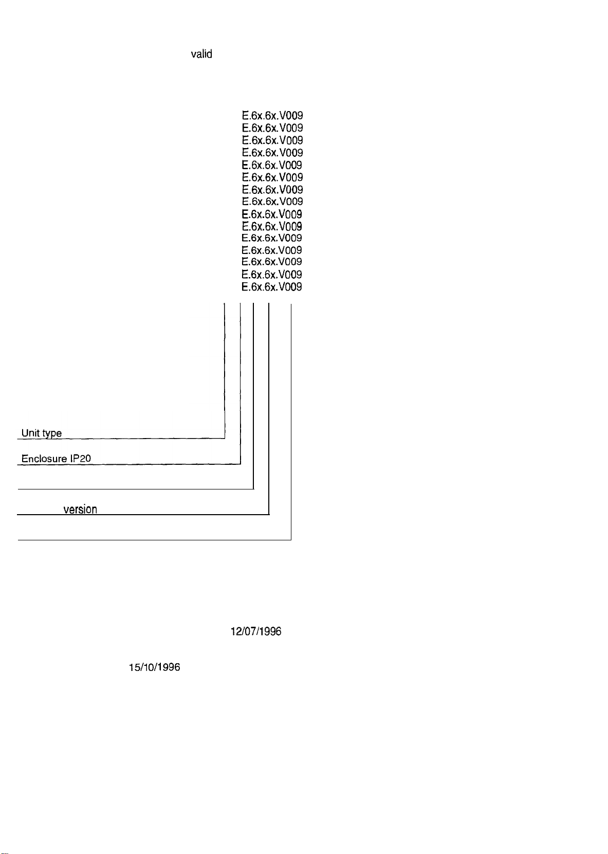
These Operating Instructions are
valid
for the units with the following nameplate data:
8601 E.6x.6x.V009
8602
E.6x.6x.V009
8603
E.6x.6x.V009
8604
E.6x.6x.V009
8605
E.6x.6x.V009
8606
E.Gx.Gx.VOO9
8607
E.6x.6x.VO09
8608
E.6x.6x.V009
8609
E.6x.6x.V009
8610
E.6x.6x.V009
8611 E.6x.6x.VO09
8612
E.6x.6x.V009
8613
E.6x.6x.VO09
8614
E.6x.6x.VO09
8615
E.6x.6x.V009
Hardware Version + index
Software
Variant number
version
Corresponds to the German edition of:
Edition of: 15/1
+ index
0/1996
12/07/1996
Page 3
How to
use
these
Operating
lnstructions...
To
locate
information on specific
contents at the beginning and to the index at the end of the
Operating Instructions.
topics,
simply refer to the table of
These Operating Instructions use a series of different
provide quick reference and to highlight
This
Symbol
refers to items of information intended to facilitate
Operation.
Notes
which should be observed to avoid possible darnage to or
destruction
Notes
operating personnel.
of equipment.
which should be observed to avoid health risks to the
important
items.
Symbols
to
lenze
1
Page 4

General safety and Operating Instructions for drive converters
in conformity with the Low-Voltage Directive 79/23/EEC
-
1. General
In operation, drive converters, depending on their
degree of protection, may have live, uninsulated, and
possibly also moving or rotating parts, as well as hot
surfaces.
In case of inadmissible removal of the required covers,
or improper use, wrong installation or maloperation,
there is the danger of serious personal injury and
damage to property. For further information, see
documentation.
All operations serving transport, installation and
commissioning as well as maintenance are to be carried
out by skilled technical personnel. (Observe IEC 364 or
CELEC HD 384 or DIN VDE 0100 and IEC 664 or
DINNDE 0110 and national accident prevention rules!)
For the purposes of these basic safety instructions,
“skilled technical personnel” means persons who are
familiar with the installation, mounting, commissioning
and operation of the product and have the qualifications
needed for the performance of their functions.
2. Intended use
Drlve converters are components designed for inclusion
in electrical installations or machinery.
In case of installation in machinery, commissioning of
the drive converter (i.e. the starting of normal operation)
is prohibited until the machinery has been proved to
conform to the provisions of the Directive 89/392/EEC
(Machinery Safety Directive - MSD). Account is to be
taken of EN 60204.
Commissioning (i.e. the starting of normal operation) is
admissible only where conformity with the EMC
Directive (89/336/EEC) has been established.The drive
converters meet the requirements of the Low-Voltage
Directive 73/23/EEC. They are subject to the
harmonized standards of the series prEN 50178/DIN
VDE 0160 in conjunction with EN 50439-1NDE 0660,
part 500, and EN 60146lVDE 0558.
The technical data as well as information concerning the
supply conditions shall be taken from the rating plate
and from the documentation and shall be strictly
observed.
3. Transport, storage
The instructions for transport, storage and proper use
shall be complied with.
The climatic conditions shall be in conformity with prEN
50178.
4. lnstallatlon
The installation and cooling of the appliances shall be in
accordance with the specifications in the pertinent
documentation.
The drive converters shall be protected against
excessive strains. In particular, no components must be
bent or isolating distances altered in the course of
transportation or handling. No cantact shall be made
with electronic components and contacts. Drive
converters contain electrostatic sensitive components
which are liable to damage through improper use.
Electric components must not be mechanically damaged
or destroyed (potential health risks).
5. Electrlcal connectlon
When working on live drlve converters, the applicable
national accident prevention rules (e.g. VB 4) must be
complied with.
The electrical installation shall be carried out in
accordance with the relevant requirements (e.g. cross
sectlonal areas of conductors, fusing, PE connection).
For further information, see documentation.
Instructions for the installation in accordance with the
EMC requirements, like screening, earthing, location of
filters and wiring, are contained in the drive converter
documentation. They must always be complied with,
also for drive converters bearing a CE marking.
Observance of the limit values required by EMC law is
the responsibility of the manufacturer of the installation
or machine.
6. Operation
Installations, which include drive converters shall be
equipped with additional control and protective devices
in accordance with the relevant applicable safety
requirements, e.g. Act respecting technical equipment,
accident prevention rules, etc. Changes to the drive
converters by means of the operating software are
admissible.
After disconnection of the drive converter from the
voltage supply, live applicance parts and power
terminals must not be touched immediately because of
possibly energized capacitors. In this respect, the
corresponding signs and markings on the drive
converter must be respected.
During operation, all covers and doors shall be kept
closed.
7. Maintenance and servicing
The manufacturer’s documentation shall be followed.
KEEP SAFETY INSTRUCTIONS IN A SAFE PLACE!
Please observe the product-specific safety and Operating Instructions stated in these Operating
Instructions.
Page 5
Table
Planning
of contents
l Feiatures
2 Technical data
2.1 General data
2.2 Dimensions
2.3
2.4
Application
2.5 CE conformity
2.51 EC Low-Voltage
2.5.2
3 Application-specific
3.1 Applications with extreme overload, peak torque up to
230% of the rated motor torque
3.2 Applications with high overload, peak torque up to 170 % of
the rated motor torque
3.3 Applications with medium overload, peak torque up to
135 % of the rated motor torque
4 Handling
4.1 Mechanical installation
4.2 Electrical installation
4.2.1
4.22
4.2.:3
4.2.4 Switching on the motor side
of the 8600 series variant dancer-Position control
Scope
of delivery
as directed
Directive (73/23/EEC)
Electromagnetit
Motor
Installation in compliance with EMC
CE-typical drive
protection
Compatibility
controller selection 19
System
(89/336/EEC)
9
11
11
12
12
13
14
15
16
19
20
21
22
22
23
24
24
25
27
5 Wiring
5.1 Power connections
5.1 .l Tightening torques of the power terminals
5.2 Control connections
52.1 Analog inputs and
52.2
Further
5.2.3 Description of the analog inputs and Outputs
5.2.4 Description of
5.2.5 Digital inputs and Outputs
5.2.6 Description of the digital iunputs and Outputs
5.2.7 Frequency output 6, fd
5.3 Operation with DC-bus supply
5.3.1 Connection of several drives
5.3.2 DC-voltage supply
5.4 Screenings
5.5 Grounding of control electronics
inputs and
Outputs
Outputs
further
inputs and Outputs
28
28
29
29
30
30
31
31
32
34
35
36
36
36
37
37
lenze
3
Page 6
6 Accessories
6.1
Brake
resistors
6.1 .l Selection of the brake resistor
6.1.2 Technical data of brake resistors
6.2 Mains
6.2.1 Selection of the mains
6.2.2 Technical data of mains
6.3 Motorfilter
6.3.1 Technical data of motor filters
6.4 Sine filter
6.4.1 Technical data of sine filters
6.5
6.6
6.6.1 Ratings of
6.6.2 Technical data of
6.7 Accessories for digital frequency networking
7 Accessories for networking
7.1 Connecting module 211 OIB-
7.2 Connecting module
7.3 Connecting
7.4 Level
7.5 Adapter
8 Initial switch-on
Chokes
Gable protection
RFI
filters
RFI
elements
converter
FIS485
Choke
Chokes
filters
RFI
filters
InterBus-S
2130lB-
for
2101 IP- LECOM-NB
(LECOM
PROFIBUS
Optical
fibre cables-LECOM-LI 53
interface
X6)
38
38
39
41
42
43
44
45
46
47
48
49
50
50
51
51
52
52
52
53
53
54
-
-
Parameter setting
1 Keypad
1.1 Key
1.2 Plain text display
2 Basic Parameter setting
2.1 Changing Parameters
2.1 .l
2.2 Save Parameters
2.3 Load Parameters
3 Basic settings
3.1
3.1 .I Controller enable
3.1.2
3.2 Configuration
3.2.1 Example of how to select a
3.3 Signal-flow
3.4 Features of
3.4.1
3.4.2 Digital frequency input
3.5 Features of
3.6 Offset and
3.7 Control mode
3.7.1 V/f-characteristic control
3.7.2 Io control
3.8 Minimum field frequency fdmin
3.9 Maximum field frequency fdmax
3.10
functions
Parameter setting by two
Operating mode
Quick stop / Select
Chart
for
Speed-controlled
(CO05
= -o- to
Setpoint
Acceleration and deceleration times Tir, Tif
-15)
setpoint
input with
setpoint
gain
adjustment
1
2
Codes
direction
master current
of rotation
configuration
Operation
55
55
55
56
56
58
58
58
59
59
60
60
62
63
64
66
66
69
68
68
69
70
72
73
73
74
-
4
lenze
Page 7
4 Closed-loop speed control
4.1 Analog act. value
4.2 Digital act. value
4.3 Frequency
4.4 Adjustment of the act. value gain
4.4.1 Automatic adjustment
4.4.2 Manual adjustment
4.5 Setting of the controller Parameters 79
4.6 Additional functions
5 Programming of the freely assignable inputs and
5.1 Freely assignable digital inputs
5.2 Functions of the freely assignable digital inputs
5.2.1 Set TRIP
52.2 Reset TRIP
5.2.3 DC-injection brake
5.2.4 JOG frequencies
5.2.5 Additional acceleration and deceleration times
5.2.6 Ramp generator stop
5.2.7 Ramp generator input = 0
5.2.8 Integral
5.2.10 Reset 1-component / D-component - dancer-Position controller
52.11
Suppression of the dancer-Position controller
5.2.12 Reset of the
5.3 Freely assignable digital Outputs, relay output
5.4 Functions of the freely assignable digital Outputs
5.4.1 Frequency below a certain threshold,
5.4.2 Maximum
5.4.3
Setpoint
5.4.4 Fault
54.5 Ready, RDY
5.4.6 Pulse inhibit, IMP
5.4.7 Act. value =
5.4.8 Act. value = 0
5.5 Monitor Outputs
5.6 Digital frequency output X9 (Option)
Pilot
action
current
reached,
indication
Setpoint
control
component = 0
Sensor
compensation
reached, Imax
RFG/O=I
TRIP
Outputs
Qmin
75
75
75
76
78
78
78
80
81
81
82
82
82
83
84
86
88
88
88
90
90
90
90
91
91
92
92
92
92
92
93
93
94
95
6 Additional open-loop and closed-loop control functions
6.1 Chopper frequency
6.1.1 Automatic
6.2 Automatic DC-injection brake
6.3 Slip compensation 97
6.4 S-shaped ramp generator characteristic 98
6.5 Limitation of the frequency setting range
6.6
Oscillation
6.7 Load-Change damping
7 Overload
7.1 Overload
(1.t
monitoring)
7.2 Overload
8 Display functions
8.1 Code set
8.2 Language
8.3 Display of
8.4 Switch-on display
8.5
Identification
chopper
damping
protections
protection
protection
actual valuesAct.
of the frequency controller
of the motor
frequency
value
reduction 97
96
96
97
98
98
98
99
99
99
100
100
101
101
101
101
lalze
5
Page 8
j
.~..,,,
,i
_,
.,>,
:,,.
.,,;’
:
>
‘.,
,_j
_’
,
,, i ,‘:,;‘,::
>, ’ ,’ ,. <.
,,>. :‘t;;,;’
, ,
j ,,’ _,,” ,,,, :.
‘. : :
,’ ,,,
,:
s ‘_ i
:
,\ “”:>
_‘;
>,,
‘.:: 9~’
:>^
I
>.
,‘: .,
:
.*‘\
,b
, ,. ,, .
;> ,.’
,_ ^“‘I
j ‘:.:‘.c,
<
,, >,>,
; : ,>,,
j
, j, :.
<
,..
‘, ::
:
,,
, > ,
,:,.,
“, ,,,
,,ii’
I
s ’ ,. j ; < >
,, j
<> ,> ”
:,,.
.‘.
_: :
~,
_,’
.
<, ,, ^
j’ “>,
,, 1.’
.,
’ ‘; :,;
,
,
>
,
>:.<.
:.
__
, >
I. *
.,,j
> ”
:
.:
’
,.
I
>
.
j j, ,,
,, ., ; ;
> j : I 0 v O,
,,I I’ :; ,,
,<
‘,
j, ,,j
,‘I ‘_,i_,
:
:
,, ,’
~
_, ,’ :, _‘. ‘,
j i :
: ‘-’
‘,,’ :,
j
<‘, ‘;
,_.i/’
.,
^
: >
1
,”
,
”
s
‘,:
I.
,.
,j,
<’
,,
’ ~7
,j
,
_i ,,,
>’
,
’
: ^
‘,
: r ”
>
,,
; “‘,,
_,;
_‘,.
z
1 ,’ ,’
:,
~‘/,Q.’ ,<~/~~,_<
,_
>,“_ ,,,.
j
> ;,
, ,.
‘, :.
,, ., j ; ’ :
;, ; ;
“. I_ ,_
r.
>
:, : ,\
-:,_
_. I
>_..
, < ’ :
>
;,“, ’ 1,.
<
:,,
: :, : <’
:;c;::,,;,,:..
a
,,
I.
>
: ,I
_‘,
,’ _.
,, ,;
,j .,
_:,.,
“”
r
~
_., ,j,
:.
:
:
r.:;
,>e.
,
.i’
_.,,
P
_, i,
: ,;
,.i& ;i
,’
> ,.
>.
‘L’), ,; ~:
,i ,, ,j i,
,,
j
,,; )II’
~
‘<
> ”
“‘< ”
<,
~
,.:
L, “,
:*
,‘,, ‘,>
0
” j,
:
r.
j
”
c,
,.*.,
‘:‘,
,
:
:’
,.,,
,_
,:‘:*.
:
‘I
I, : :.
., “,
j
‘, ,, ,,
., .,’
(<,.
.’
_
,.,
9 Dancer-Position control
9.1 Application examples
9.1.1
Winding drives
9.1.2
Line drives
9.1.3 Grinding and cutting-off wheel drives
9.2 Control structure of dancer-Position control with
Pilot
control
for winding drives
9.2.1 Diameter detection
:
9.2.2 Dancer-Position controller
9.3 Loop or dancer-Position control for line drives
9.4 Grinding or cutting-off wheel drives
9.5 Adjustment of analog inputs
9.6
Selection
of the
configuration
9.7 Diameter and radius detection
9.7.1 Signal of the ultrasonic Sensor: distance
9.7.2 Signal of the ultrasonic Sensor: radius
9.7.3
Further
9.7.4 Gain adjustment - radius
information
about
the radius detection
Signal
Signal
Signal
9.7.5 Limits of the radius calculation
9.7.6 Operation without
diameter Sensor
9.8 Adjustment of the dancer-Position controller
9.8.1
Setpoint
Provision
9.8.2 Winding or unwinding
9.9 Setting of the PID controller
9.9.1 Overlay of Position controller
9.9.2 Conversion of modulation of dancer-Position controller to field frequency
9.9.3 Limitation of the modulation of the dancer-Position controller
9.10 Diameter compensator
9.10.1
,’
9.10.2 Sensorless
Reset of the
diameter
diameter
compensator
detection
9.11 Input of correction value
9.12 Application: Tandem
9.13.1
Digital frequency output
9.12.2 Information
about
9.13 Application: Loop control with
9.14 Signal flow
or
-202-)
Chart
winder
the
Slave
drive
Speed
adaption
for dancer-Position control (CO05 =
-2Ol-
10 Torque controller
10.1 Features
10.2 Setting of the torque controller
10.3 Adjustment of analog inputs
10.4 Adjustment of the IO setpoint
10.5 Adjustment of the Imax limit
10.6 Adjustment of the torque controller
10.7 Signal flow
Chart
for torque control (CO05 =
-2O-
or
-2l-)
11 Code table
:,
102
102
102
103
103
104
104
105
105
105
106
108
108
108
109
109
110
111
111
112
112
113
113
114
115
115
115
116
117
117
118
118
118
119
120
122
122
123
124
126
126
126
128
130
_
^
-
6
lenze
Page 9
12 Serial intetfaces
12.1 LECOMI interface X6
12.2 LECOM2 interface (Option)
12.3 LECOM
12.3.1 Controller address
12.3.2 Operating state
12.3.3 Controller state
12.3.4 Pole pair number
12.3.5 Baud rate
12.3.6 History of reset faults
12.3.7 Code bank (LECOMI)
12.3.8 Enable automation interface
12.3.9 High resolution data
12.4 Attribute table
Codes
(LECOMl)
Service
(LECOM2)
1 Fault
2 Warning
3 Monitoring
4 Checking the power
4.1 Checking the mains rectifier
4.2 Checking the power
4.3 Checking the voltage supply on the control board 8602MP
indication
Stage
Stage
Index
7
Page 10

lenze
Page 11

Planning
1
Features of the 8600 series
variant dancer-Position control
In addition to numerous
various functions
which
used for winding applications.
Another possibility is to activate a torque control.
For more detailed information
chapters
9 and
10.
Power Stage
l Wide mains voltage range: 3 x 330 to 528V AC or
470 to 740V DC
l Controllers with
.
4kHz
chopper
l Output frequency up to
V/f-rated frequency up to 960Hz
l Overload
l Overload monitoring
.
Integrated brake transistor, external brake resistors in
capacity
enclosure as
l Connections for DC bus supply
Standard
functions, this variant offers
are required for a dancer-Position control
about
the
special
functions see
IGBTs,
protected against short circuits
frequency, adjustable up to
16kHz
480Hz,
up to 200% rated
tan
be set
current
for a short time
Option
IP20
Control Stage
.
Digital control unit with
l Simple Parameter setting and diagnosis using keypad and
line display in German, English, and
.
Parameter setting
l
Vif-characteristic
l High breakaway torque by magnetizing-current control
l Constant
l Speed control using DC
l Current limitation with
l Motor overload monitoring via PTC input
l Serial
interface (RS232C/RS485)
Speed
control with linear or
due to
16-bit
during
Operation
Slip compensation
tacho
V/f
lowering for stall-protected Operation
microprocessor
French
language
Square
characteristic
or incremental
encoder
for external Parameter setting
and Operation
.
Field bus connecting
modules
as
Option tan
be integrated
two-
Page 12
SpeciaI functions
l Dancer-Position controller with speed and
diameter
evaluation
l
Diameter
l Soft insertion of the dancer-Position controller via ramp
generator or
l Sensor compensator for fault and
l Torque control with
detection
multiplication
via analog input
with the main
Speed limitation
diameter
setpoint
corrections
function
Approvals
+
VDE 0160, VDE reg.-no. 86694
l UL 508, file no. 132659
(types
8602 to 8611)
-
-
Page 13
2
Technical data
2.1
Mains voltage:
Output voltage:
Output frequency:
Chopper frequency:
Threshold of the integrated brake
chopper
Enclosure:
Ambient temperature:
Noise
Permissible
permissible
Influence of installation altitude on 1000 m: 100% rated
the rated
General data
immun@
pollution
current:
3 x
46OV
Permissible voltage range:
(as alternative:
3 X 0
(V -
When using a mains
reduced to approx. 96% of the mains voltage.
0 to
4kHz factory
765 V DC in the DC bus
Steel-sheet
0 to 50°C during Operation
(for rating see page 19)
-25 to 55°C
-25 to 70°C
Severity
Pollution level
l 2 to VDE 0110,
corrosive
2000 m: 95% rated
3000 m: 90% rated
4000 m: 65% rated
AC, 45 to 65 Hz
470...740\1
t0
Vmains
fd with 400V at
50Hz,
adjustable up to
setting,
housing,
during
storage
during
transport
class
4 to IEC 801-4
or explosive
part
50Hz,
Choke,
adjustable from 2 to
IP20
2. The
gases.
current
current
current
current
330...526
DC
adjustable, mains-independent)
the maximum possible output voltage is
480Hz
to DIN 40050
supply)
controller
V
16kHz
should not be exposed to
lmze
11
Page 14
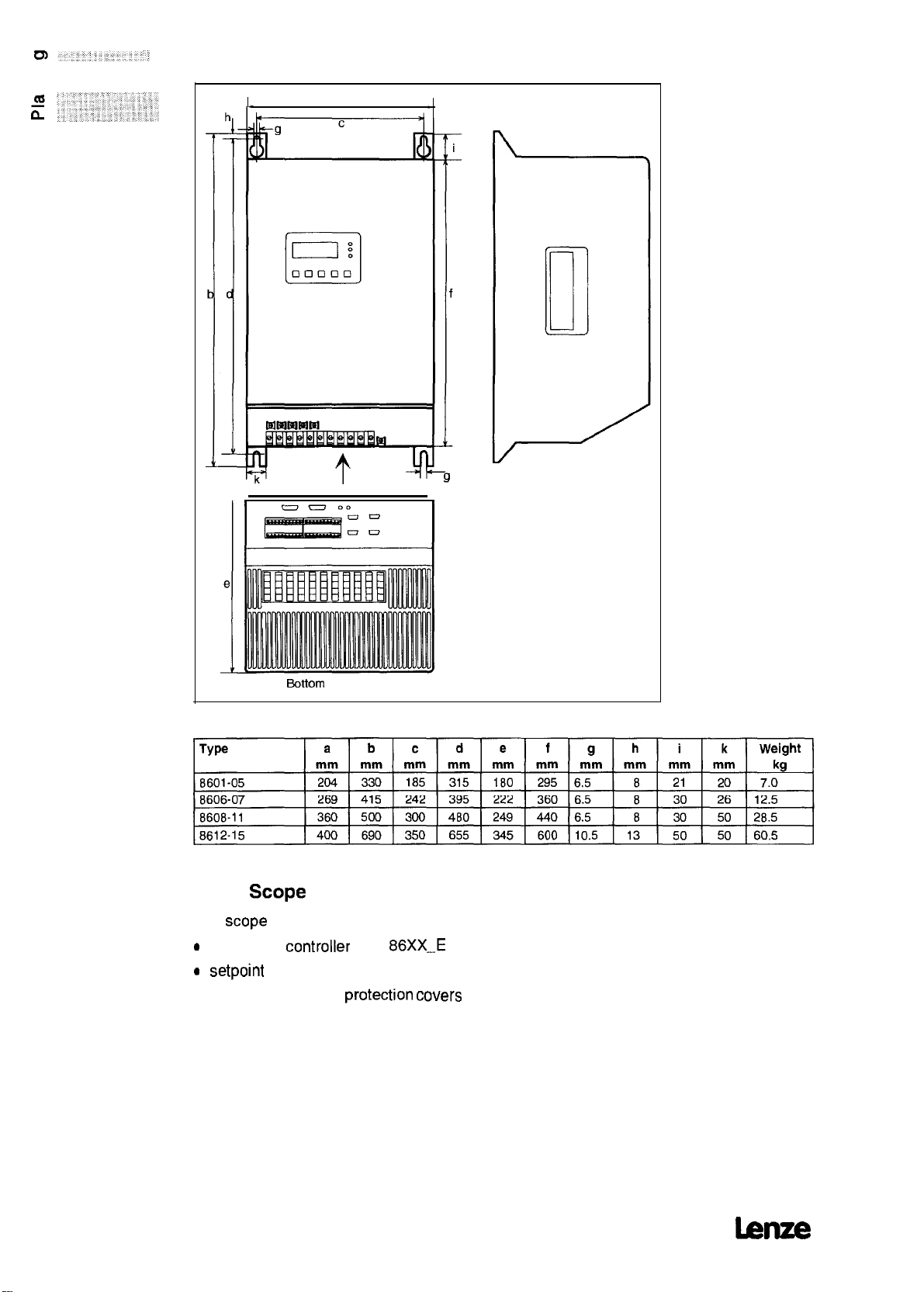
2.2
Dimensions
a
Bottom view
2.3 Scope
The
scope
0
frequency
0 setpoint
l accessory kit incl.
l Operating Instructions
of delivery
of delivery includes:
controller
Potentiometer
type
protection covers
86XX-E
and plug-in terminals
12
lenze
Page 15
2.4
Application
as directed
-
-
The 8200 series consists of electrical devices which are designed
for application in industrial power installations.
The controllers are directed
-
as components for the control of variable
AC motors
-
for the installation into control cabinets or control boxes
-
as controllers for the installation of drive
The controllers comply with the
EC Low-Voltage Directive.
Drive Systems with 8600 controllers which are assembled
according to the requirements for CE-typical drive
chapter
The CE-typical drive
intended
-
-
The CE-typical drive Systems are not suited for the connection
to IT mains (mains without earth-potential reference)
the earth-potential reference of the RFI filter.
The controllers are not appliances but directed as components
to be assembled into drive Systems for industrial use.
The controllers themselves do not form machines for the
purpose of the EC Machinery Directive.
4.2.2) comply with the EC EMC Directive.
Systems
for the Operation at public and non-public mains
for the application in industrial, commercial and residential
areas
protection
with the 8600 controllers are
Speed
drives with
Systems
requirements of the
Systems
(see
because
of
lenze
13
Page 16

2.5 CE conformity
What is the purpose of EC directives?
EC directives are issued by the
for the determination of common technical requirements
(harmonization) and cet-tification procedures within the
Community. At the moment, there are 21 EC directives of product
ranges.
the member states. A certification issued by one member state is
valid automatically without any
states.
The texts of the directives are restricted to the essential
requirements. Technical details are or will be determined by
European
What does the CE mark imply?
After a verification, the conformity to the EC directives is
affixing a CE mark. Within the EC there are no commercial barriers
for a product with the CE mark. The enclosure of a conformity
cet-tification is not necessary according to most directives.
Therefore, the customer is not able to appreciate
EC directives applies to a product and
are considered in the conformity verification.
A drive
the Low-Voltage
Directive
The CE conformity of the installed
responsibility of the
Systems
conformity to the EMC
The directives are or will be
harmonized Standards.
controller
only general recommendations have been issued so far.
(see page
with the CE mark itself corresponds exclusively to
Directive.
User.
26ff),
Lenze has already proved the CE
Directive.
European
fut-ther
For the compliance with the EMC
For the
installation
Council and are intended
European
conver-ted
approval in all other member
which
machine
to national laws of
certified
which
of the 21
harmonized Standards
remains the
of CE-typical drive
by
What is the aim of the EMC
The EC
effective
disturbances or be affected by such disturbances.
The aim is the limitation of the generation of
disturbances so that the Operation of radio and telecommunication
Systems
immunity of the equipment against
ensured so that the Operation
What is the
The Low-Voltage
for use with a rated voltage between 50V and 1 OOOV AC and
between 75 and 1500V DC and
The use of e.g. electrical equipment in explosive atmospheres and
electrical
The
which
also be designed to
Directive
for “equipment”
and other equipment is possible and that a suitable
objective
does not endanger the safety of man or
relating to
objective
Parts
in passenger and goods lifts are excepted.
of the Low-Voltage
of the Low-Voltage
Directive
conserve
Directive?
Electromagnetit
which
may either
tan
be achieved.
is
effective
under
Directive
material
Compatibility is
Cause electromagnetic
electromagnetic
electromagnetic
for all electrical equipment
normal ambient conditions.
is to ensure that
assets.
disturbances is
Directive?
animals
is
placed
only
that electrical equipment
on the market. lt should
14
lenze
Page 17
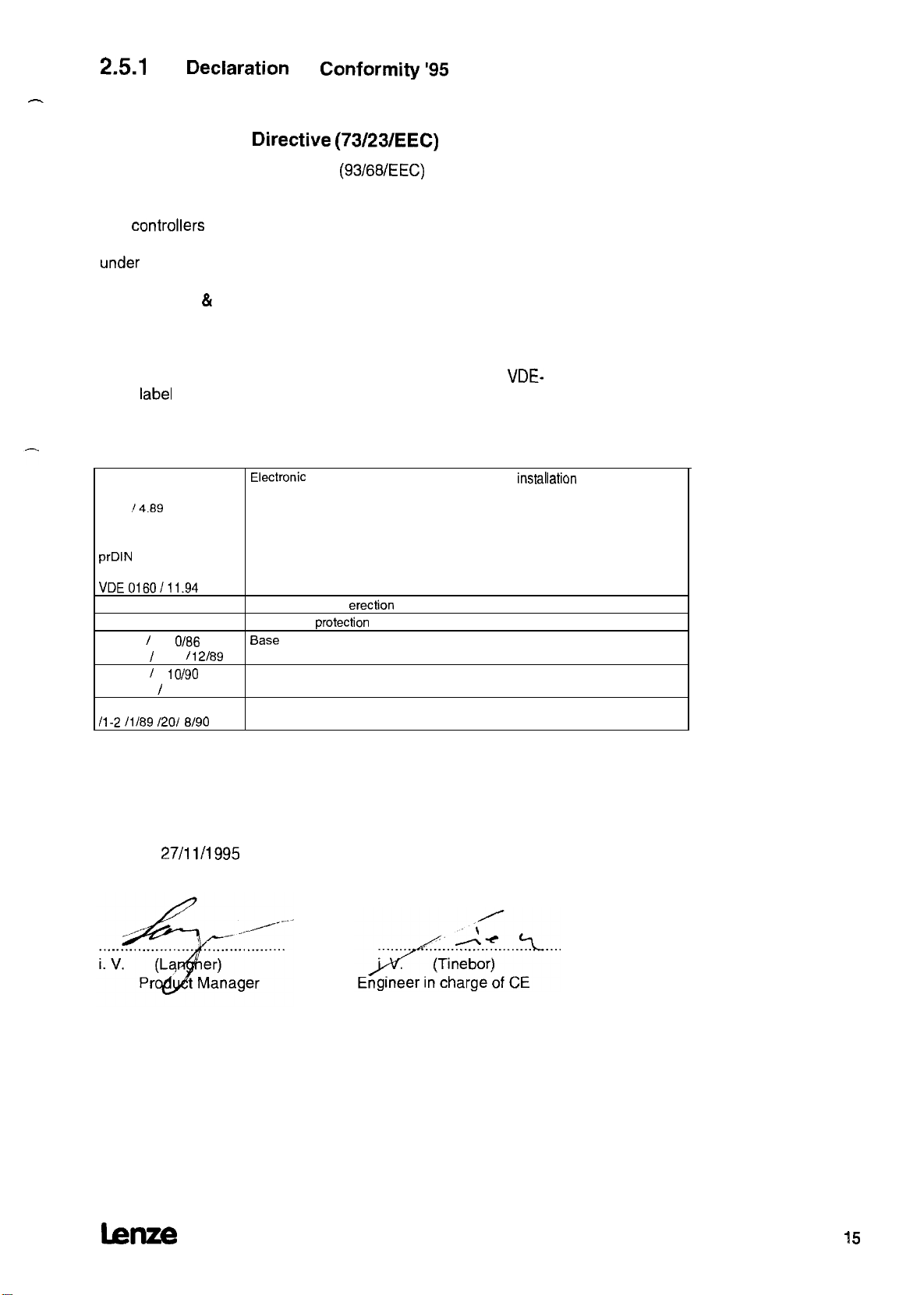
2.5.1
EC
Declaration
-
for the purpose of the
of
Conformity ‘95
EC Low-Voltage
amended by:
The
controllers
of the 8600 series were developed, designed, and
Directive (73/23/EEC)
CE mark directive
(93/68/EEC)
manufactured in compliance with the above-mentioned EC directive
under
the sole responsibility of
Lenze GmbH & Co KG, Postfach 101352, D-31763 Hameln
The compliance with the protective requirements of the above
mentioned EC directive was confirmed by the award of the
EMC
label
of the accredited test laboratory VDE Prüf- und
Zertifizierungsinstitut, Offenbach.
Standards and regulations considered:
DIN VDE 0160
5.88
+ Al
14.69
+ A2.110.66
prDIN
EN 50176
Classification
VDE0160/11.94
DIN VDE 0100
EN 60529
IEC 249 / 1 1 OB6
IEC 249 / 2-15 /
IEC 326 / 1
EN 60097 / 9.93
DIN VDE 0110
/l-2 /1/89 1201 EU90
12/89
IO/90
Electronie
Standards for the
Degrees of
Base
Printed circuits, printed boards
Creepage distances and clearances
equipment for use in electrical power
erection
of power installations
protection
material for printed circuits
VDE-
installation
Hameln,
lsnze
27/11/1995
15
Page 18
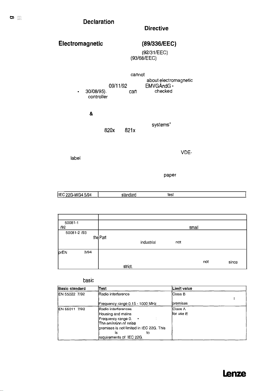
2.5.2 EC
for the purpose of the EC
Declaration
of Conformity ‘95
Directive
relating to
Electromagnetit
amended by: First amended directive
The controllers of the 8600 series
Operation for the purpose of the regulation
compatibility (EMVG of
directive - of
integrating the
30/08/95).
controller
Compatibility
CE mark directive
09/11/92
The EMC
into a drive System.
(89/336/EEC)
(92/31/EEC)
(93/68/EEC)
cannot
and 1st
tan
only be
be driven in stand-alone
about electromagnetic
EMVGÄndG -
checked
amended
when
Lenze GmbH & Co KG, Postfach 10 13 52, D-31763 Hameln
declares that the described “CE-typical drive
controllers of the type
820~
und
821~
comply with the above
Systems”
with the
mentioned EC directive.
The compliance with the protective requirements of the above
mentioned EC directive was confirmed by the award of the
EMC
label
of the accredited test laboratory: VDE Prüf- und
VDE-
Zet-tifizierungsinstitut, Offenbach
The conformity evaluation is based on the working
Paper
of the
product Standard for drive Systems:
IIEC 22G-WG4 5/94
1
EMC product
standard
Considered generic Standards:
Generic
EN
192
EN
(used in addition to
requirements of IEC The emission of noise in
22G) IEC 22G.
prEN
Considered
Standard
50081-1
50081-2 193
50082-2
Generic Standard for the emission of noise
Part 1: Residential areas, commercial premises, and
Generic Standard for the emission of noise
the Part
2: Industrial premises
3194 Generic Standard for noise immunity
basic
Part 2: Industrial premises
The requirements of noise immunity for residential areas were
these are less
stritt.
Standards for the test of noise emission:
Housing and mains
15 - 1000 MHz
Ise
including specific
industrial
in industrial
test
premises is
methods for power drive Systems
small
businesses
not
limited in
not
considered
for use in residential and commercial
n
industrial premises
since
I
16
Standard is used in addition to the
bue
Page 19
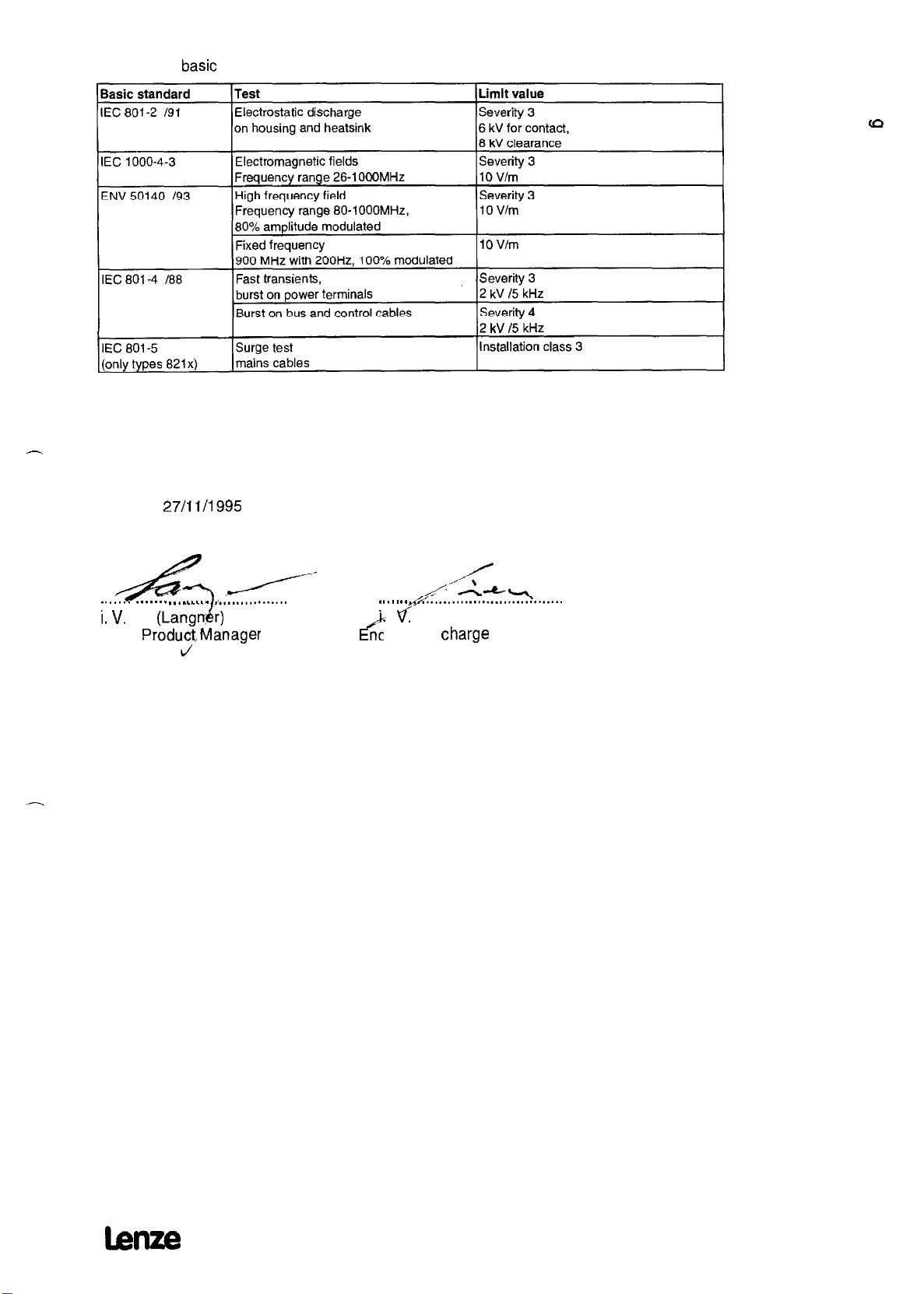
Considered
-
basic
Standards for the test of noise immunity:
Hameln,
4
. . . . . . . . . . . . . . . . . . . . . . . ..
i. V.
27/11/1995
--l/-
(Lang&)
ProdudManager
d
I................
* . . . . . .
‘; f
i’
ngineer in
/’
-1”w
A
d...............................
(Tinebor)
Charge
of CE
lenze
17
Page 20
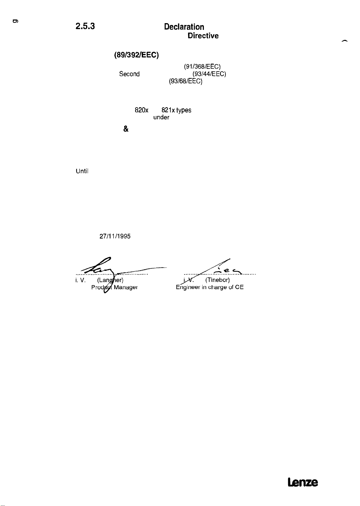
2.5.3
EC Manufacturer’s
Declaration
for the purpose of the EC
Directive
relating to
-
Machinery
amended by: First amended directive
The controllers of the
designed, and manufactured
(89/392/EEC)
Second
CE mark directive
amended directive
820~
and
under
(91/368/EEC)
(93/44/EEC)
(93/68/EEC)
821~ types
the sole responsibility of
were developed,
Lenze GmbH & Co KG, Postfach 10 13 52, D-31763 Hameln
The controllers are directed to be installed in a machine or to be
assembled together with other components to form a machine or a
System. The controllers on their own are not machinery for the
purpose of the EC directive relating to machinery.
Until
the conformity of the machinery where the controllers are to
be installed with the regulations of the EC directive relating to
machinery is proved, commissioning of the controllers is prohibited.
Hameln,
27/11 0995
18
Page 21
3
-
3.1
Application-specific controller selection
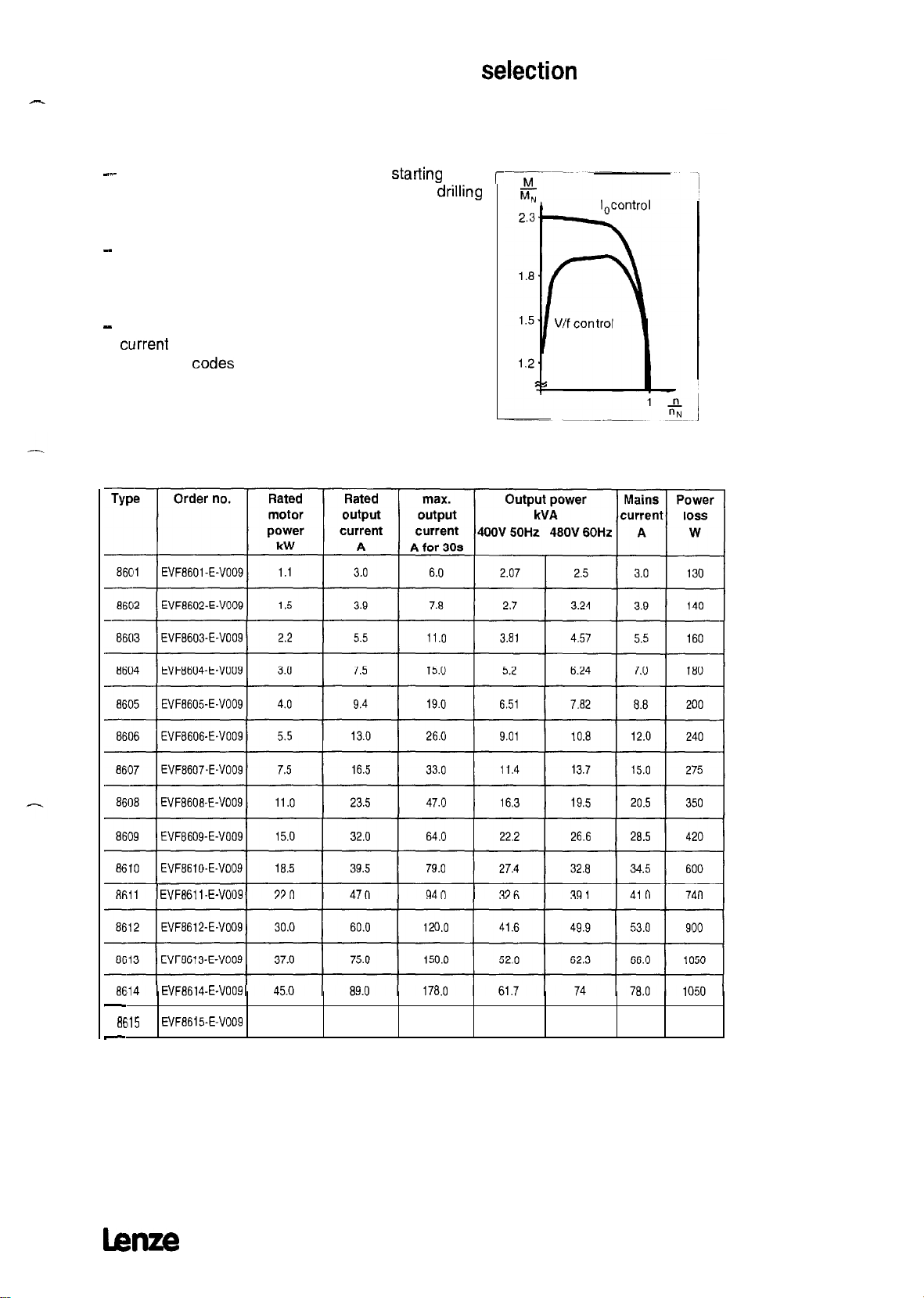
Applications with extreme overload,
peak torque up to 230% of the rated motor torque
--
For applications where a very extreme
overload torque are necessary (e.g. presses,
machines).
-
The controller provides 200% of the rated torque for
a maximum of 30s.
With cyclic overload, the ratio between overload to
cycle time must not exceed 0.2.
-
For these applications, the monitoring of the output
current
is set to
using the
(factory setting)
-
Please note that a maximum ambient temperature of
50°C is permissible.
Codes
Operation with rated power
Cl 19 and Cl20 (see page 82)
starting
and
drilling
r
8Eil5
-
hue
EVF8611-E-V009
EVF8614-E-V009
EVF13615-E-V009 55.0 110.0 220.0 76.2 91.4 96.0 1270
19
Page 22
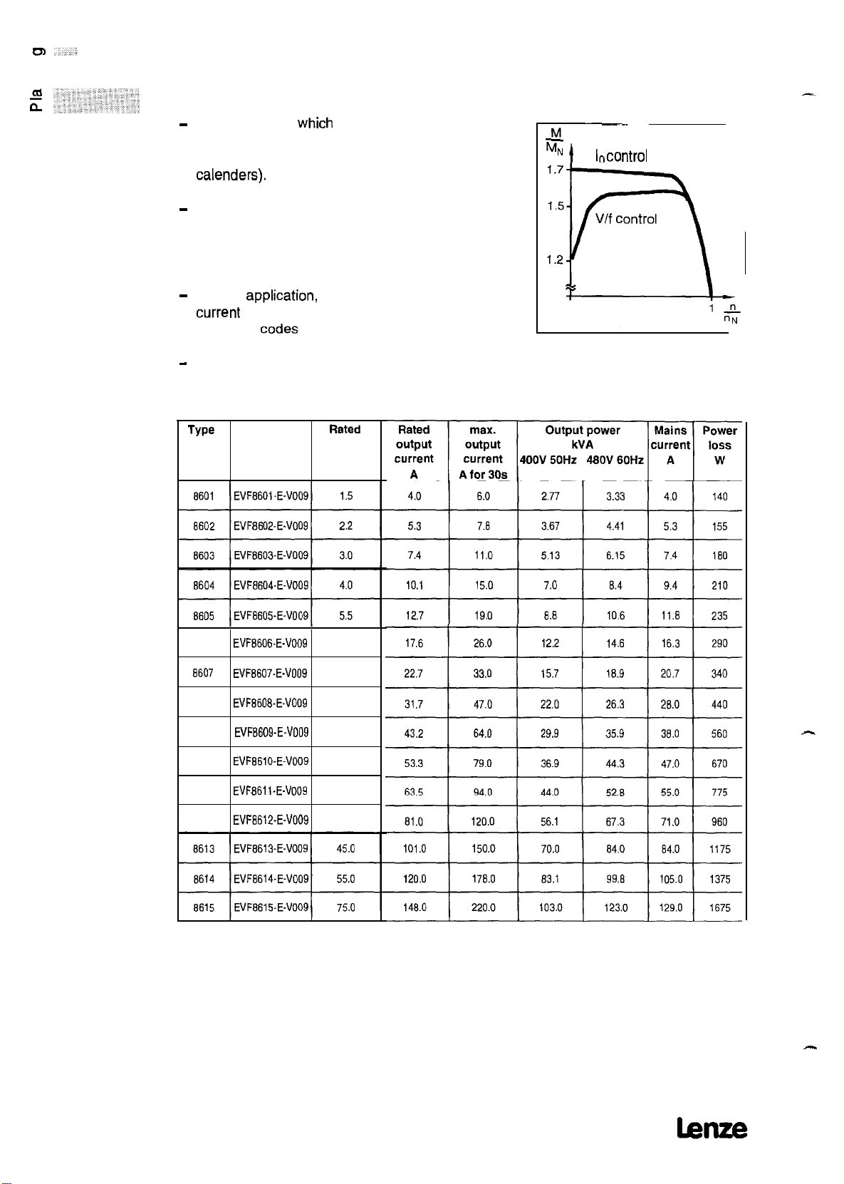
3.2
Applications with high overload,
peak torque up to 170 % of the rated motor torque
-
For applications
overload behaviour of a controller (e.g. general
mechanical engineering, hoists, travelling drives,
calenders).
-
The controller provides 150% of the rated torque for
a maximum of 30s.
For cyclic overload, the ratio overload to cycle time
must not exceed 0.1.
-
For this
current
using the
-
Please note that a maximum ambient temperature
of 45°C is permissible.
TYQe
application,
is set to Operation with
Order no.
which
require a Standard
the monitoring of the output
increased power
Codes
Cl 19 and Cl20 (see page 82)
Rated
motor
power
kW
M,
Mt
~~
lncontrol
8606 EVF8606-E-V009
6607 EVF8607-EA'009
8608
EVF86IWE4'009
8609 EVF8609-E-V009
8610 EVF8610-E-V009 22.0
8611 EVF8611-E-V009 30.0
8612 EVF6612-E-V009 37.0
7.5
11.0
15.0
18.5
-
-
20
Page 23
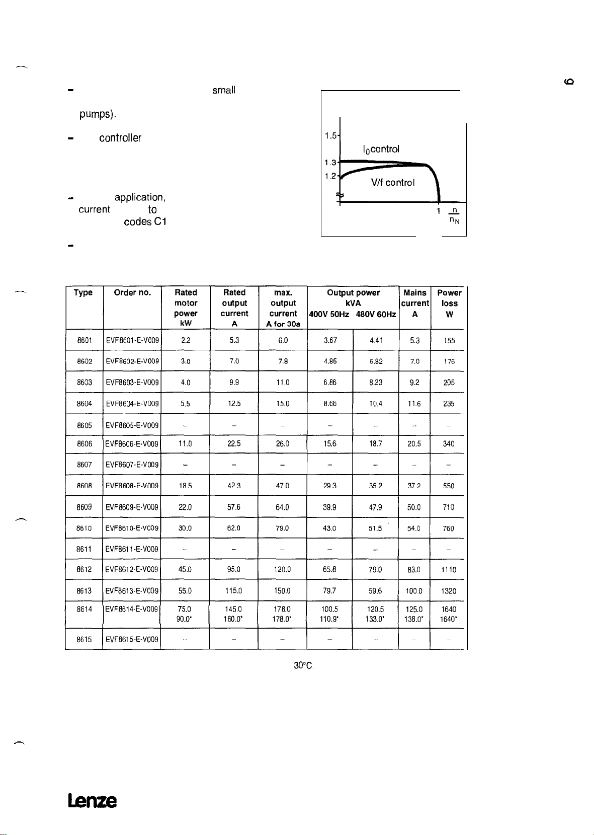
3.3
Applications with medium overload,
peak torque up to 135 % of the rated motor torque
-
For applications where only a
overload torque are necessary (e.g. Ventilators,
w-w+
-
The
controller
provides 110% of the rated torque for
a maximum of 30s.
For cyclic overload, the ratio overload to cycle time
must not exceed 0.1.
-
For this
current
using the
-
Please note that a maximum ambient temperature
application,
the monitoring of the output
is set to Operation with
Codes Cl
19 and Cl20 (see page 82 )
of 40°C is permissible.
small
starting and
maximum power
M
MN
10control
EVF8606-E-V009
-
EVF8614-E-V009
l These data are valid for a maximum ambient temperature of
30°C.
x
Lenze
21
Page 24

4
Handling
4.1
Mechanical installation
These frequency controllers must only be used as built-in
units.
Install
the controller
bottom.
Allow
a free space of
controllers 8612 . . . 8615 this free space must also be allowed
at both sides. Ensure unimpeded Ventilation of cooling air.
If the cooling air contains pollutants (dust,
grease,aggressive
functions,
separate air
If the controller is permanently subjected to Vibration or
shaking,
suitable preventive measures must be taken,
duct,
shock
vettically
100mm
gases ), which
installation of a
absorbers may be necessary.
with the terminal
at the top and bottom. For the
flakes,
may impair the controller
fiter,
regular
Strips
at the
cleaning,
e.g.
etc.
-
22
-
Page 25
4.2
l The Controllers contain sensitive electrostatic compontents.
Electrical
Priior
to assembly and Service operations in the area of the
controller connections, the
installation
Personne1
must be free
of
electrostatic Charge.
These persons
fixing screw or another grounded metal
tan discharge
themselves by
part
touching
the PE
in the control
cabinet.
l All control inputs and Outputs of the controller are mains-
isolated. The mains isolation has a
inputs and Outputs must be integrated into another
protection
against
direct
contact.
basic
insulation. The control
level
of
Use insulated operating elements, connect the mechanical
screw
fastener
of the
setpoint
potentiomenter (accessory kit)
with PE.
l Unused control inputs and Outputs must be protected with plugs
or the
covers
included in the delivery.
l When using current-operated protective equitpment:
-
The
-
controllers
As result, a DC-fault
are internally equipped with a mains rectifier.
current
may prevent the tripping of the
current-operated protective equipment after a short-circuit to
frame.
Therefore, we recommend additional measures such as
protective multiple
current-operated
-
When dimensioning the tripping
e.1.c.b.
please observe, that the capacitive leakage currents
between
cable screens
earthing
e.1.c.b.
and RFI
or universal-current sensitive
current
of current-operated
filters
may result in false
tripping.
l The regulations
conductors must be observed. The
conductor must be at least as large as the
cable
connection.
l In the
case
about
of
condensation,
the
minimum Cross section
Cross-section
Cross section
only connect the Controller vwhen
of PE
of the PE
of the
visible moisture has evaporated.
l Before first switching-on of the controller check whether there is
an
earth
fault at the output side, if so, remove it.
which
occur
during
Operation will be detected, the controller will
be switched off and indicate the fault message
l The internal
current
limitation
tan
be overloaded when
Earth
“OCl”.
faults
connecting or disconnecting the controller very often. With cyclic
mains connection, the Controller
tan
be switched on every 3
minutes.
l Replace
defective
fuses only with the specified type and when
no voltage is applied.
The controller remains live for up to 3 minutes after mains
disconnection.
hze
23
Page 26
4.2.1 Motor protection
The units do not have a
For monitoring the motor temperature
tan
be used.
The connection possibilities are shown on page 28.
When using group drives, a motor protection relay is required for
each
motor.
When using motors which do not have a suitable insulation for
controller Operation:
-
Connect motor filters for protection (see page 45).
Please contact your motor manufacturer.
Please note:
These frequency controllers generate an output frequency of up to
480 Hz when set correspondingly. The connection of a motor which
is not suitable for this frequency may result in a hazardous
overspeed.
full
motor protection.
PTCs
orthermal contacts
4.2.2 Installation in compliance with EMC
-
l Lenze has built up typical drives with these controllers and has
verified the conformity. In the following this
System
is called
“CE-typical drive system”.
If
you observe the
CE-typical drive
Problems
and you
pat-tially
System,
tan
easy measures for the
the controller will not
be sure to comply with the EMC
installation
Cause
of
any EMC
Directive.
l The following configurations
-
The user himself
tan
their integration into the drive
tan
now be selected by the
determine the
System
System
components and
and is then held
User:
responsible for the conformity of the drive.
-
The user
tan
select the CE-typical drive
System
for which
the manufacturer has already proved the conformity.
For deviating installations, e.g.
-
use of unscreened cables,
-
use of group filters instead of the assigned RFI filters,
-
without mains
Choke
the conformity to the CE-EMC Directives requires a check of the
machine
or
System
regarding the EMC limit values.
The user of the machine is responsible for the compliance
with the EMC
Directive.
_-
24
Page 27
4.2.3 CE-typical drive
-
Components of the CE-typical drive
System
sytem
-
Controller,
assembly board.
The
chapter
RFI
System
filter and mains
components are
Choke
are mounted on one
functionally
wired according to the
5, section: Planning of the Operating Instructions.
Installation of CE-typical drive Systems
The
electromagnetic
method and accuracy of the
compatibility of a
installation. Special care
machine
depends on the
must be
taken of:
l filters,
l
screens
l grounding.
and
Filters
Only use suitable mains filters and mains Chokes.
Mains filters reduce impermissible high-frequency disturbances to a
perrnissible value.
Mains
caused
Motor cables
Chokes
reduce low-frequency disturbances, especially those
by long motor cables.
which
are longer than 50 m must be protected
additionally (motor filter or sine filter).
Screens
All cables from and to
Lenze
System
cables meet these requirements.
Ensure that the motor
(Signal
cables and mains cables). Mains input and motor output
must not be connected to one terminal
Lay cables as
close
t3e controller
cable
is laid separately from the other cables
must be screened.
Strip.
as possible to the reference potential. Dangling
cables are like antennas.
Grounding
Ground
all metall-conductive components
mains Chokes) using suitable cables from a
Maintain the min.
regulations. For EMC, the
the
Cross
section.
Cross sections
surface
prescribed in the safety
of the contact is important, not
lmue
(controllers,
central Point
mains filters,
(PE bar).
25
Page 28
Installation
l Connect the Controller, mains fitter, and mains
Choke
to the
grounded mounting plate. Zinc-coated mounting plates
permanent contact. If the mounting plates are painted, the paint
must be removed in
9
When using several mounting plates they
with as large surface as possible
l Connect the
Screen
every case.
must
(e-g.
using
of the motor cable to the
be connected
topper
bands).
Screen
connection
of the Controller and to the mounting plate of a surface as large
as possible. We recommend to use ground
metal mounting
surfaces
to connect the
clamps
Screen
to the mounting
on bare
plate with as large surface as possible,
allow
a
-
screened cable
If contactors, motor
protection
switches or terminals are located
urface
in the motor cable, the screens of the connected cables must
also be connected to the mounting plate with as
[arge
surface
as possible.
PE and the
box.
Metal
connection of the
Screen
should be connected in the motorterminal
cable glands at the motor
Screen
and the motor housing with as large a
terminaJ
box ensure a
surface as possible.
If
the mains cable between mains filter and Controller is longer
than 0.3 m, the cable must be screened. Connect the
the mains cable directly to the Controller
moduie
Screen
and to the
of
mains filter and connect it to the mounting plate with as large as
possible surface.
When using a brake resistor, the
cable
must
be directly connected to the
Screen
of the brake resistor
controller
and the brake
resistor and it must be connected to the mounting platte with a
surface
The control cables must be screened. Digital
as large as possible.
contra1
cables
must be screened at both ends. Connect the screens of the
contra! cables to the
leaving as
little
Screen
connections of the Controllers
unscreened cable as possible.
When using the Controllers in residential areas an additional
screening with a damping of Z 10 dß is required to
limit
the
noise emission. This is usually achieved by installation into
enclosed, grounded conrol cabinets or boxes made of metal.
26
Please note:
l If units,
which
do not comply with the noise immunity EN
2 required by the CE, are operated next to the Controllers, an
electromagnetic
interference of these units is possible.
50082.
lenze
Page 29
Part of the CE-typical drive
System
on mounting plate
-
Ll LZ
L3 Connection mains fuse
Ll LZ
L3 Connection mains fuse
Paint-free bare metalPaint-free bare metal
^^^A^_, -...a----
, contact surfaces
Ill
I
-.
Conductive
connection between
mounting plate and
Cables between mains filterCables between mains filter
and controller longer than 0.3 m
PE connection
-
and controller longer than 0.3 m
must be screened
n.mmn,TA
Screened
control cables
/’ c’
I /’
6.’
,,
4.2.4 Switching on the motor side
Switching on the motor side is permissible for an emergency stop
as
weil
as
during
normal Operation.
Please note that when switched with the controller enabled, this
may
Cause
the fault message
long motor cables, the fault
capacitances
of the
device
tan become
is triggered. In these
to reduce the fault currents
OCl (shott circuitiearth
current
on the interfering cable
fault). For
so large that the short circuit monitoring
cases,
(See
a motor filter is
page 45).
necessary
Screened motor cable,
connect
Screen
also at the motor side,
large
cross-section
contact to the motor
housing required
to PE
kue
27
Page 30
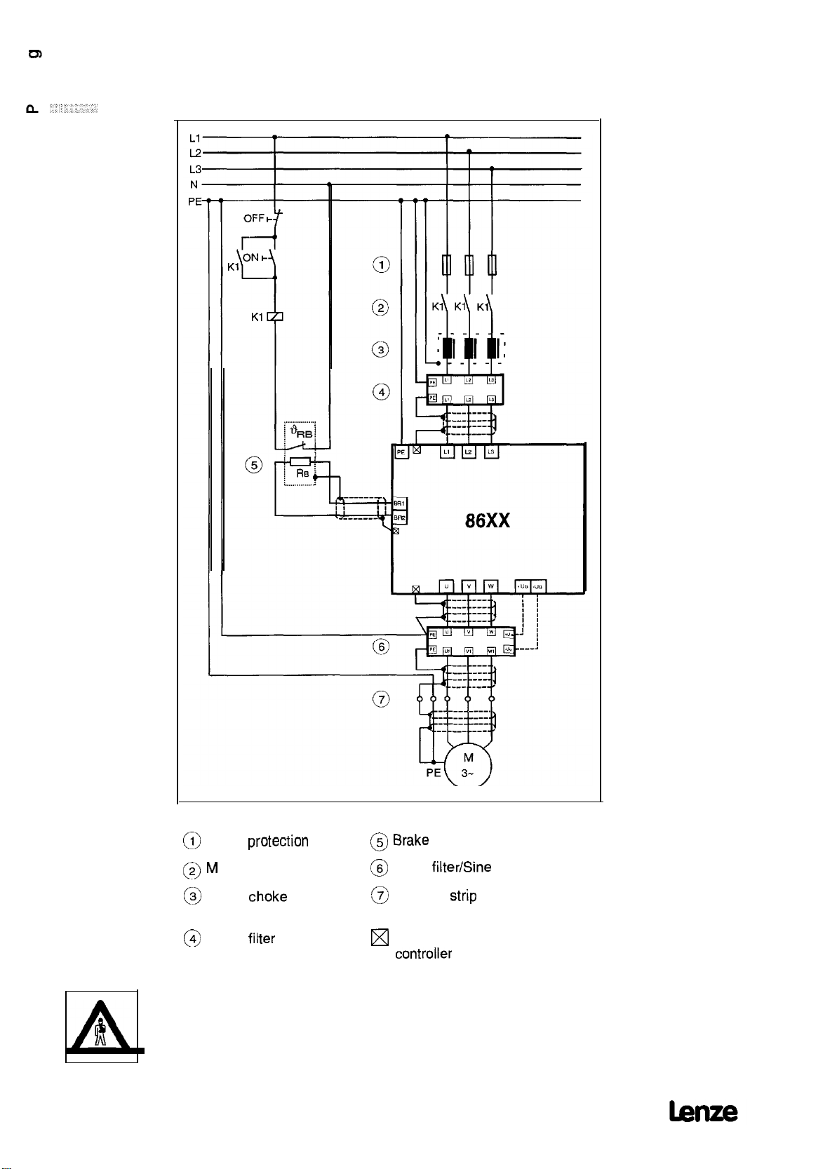
5
Wiring
5.1
Power connections
28
@
Gable
(3 M
(3>
Mains
@
Mains
All power terminals remain live up to 3 minutes after mains
disconnection!
protection
ains contactor
choke
filter
@ Brake
@
(3
[XI
resistor
Motor
Terminal
Screen connections at the
filterEine
cabinet
controller
filter
Strip
in the control
Page 31

5.1.1
Tightening torques of the power terminals
Type
Tightening 0.6...0.8
torque (5.3...7.1
8601...8605
Nm
Ibfin)
8606,8607
1.2...1.5
Nm
(10.6...13.3
Ibfin)
8608...8611
1.5...1.8
Nm
(13.3...16
8612,8613 8614,8615
6...8
Ibfin)
Nm
(53,..70Ibfin)
15...20
Nm
(133...177 Ibfin)
5.2 Control connections
Layout:
-
,:T
EB39404144 45
x3
KIlK14Al
x4
Xl
to x4: Control terminals
x5:
X6:
Input of digital
LECOM interface
frequency/incremental
(RS232/485)
encoder
X8: 2nd input of digital frequency/incremental encoder
(Option)
x9:
Xl 0, Xl
Vl,
v2;
Output of digital frequency (Option)
1:
Field bus connections
(Option, e.g.
2110lB
for
Displays for field bus Options
InterBus-S)
Note
Always connect the plug-in terminals
-
connectors Xl to X4.
When not using the interface plugs (plug-in connectors) X5 and X6
protect
them with the supplied
lt is possible to
using switches
the switches, remove the
Change
the
(See chapters
cover
functions
5.2.1 to 5.2.7, page 30ff). To
In addition to this, there are numerous possibilities to
inputs and Outputs of the device using
(accessory
covers.
of
cetiain
of the device.
Codes (See
kit) to the plug
control terminals
adjust
Change
page
the
81ff).
-
29
Page 32

52.1 Analog inputs and Outputs
Setpoint 2 Feedback Setpoint 1
5.2.2
Further
inputs and Outputs
PA
R >
2.2k
(unipolar
setpoint)
(bipolar
setpoint)
X5,
X8 Pin 4
Monitor Outputs
30
temperatu
monitoring
thermal
contact
re-
relay
output
incremental
SUPPlY
encoder
Page 33

5.2.3 Description of the analog inputs and
Analog inputs
-~
-erminal
Switch setting Use
(factory setting)
1
Setpoint
LevellResolution
2
Outputs
Parameter
setting see
s,
[-[Kl
zrF j Setpoint 1,
Voltage supply for
Potentiometer
Analog Outputs (monitor Outputs)
Terminal
iö-
62
Switch setting
Use
(factory setting)
Internal
Monitor 1 (Output
frequency)
Master
ground (GND)
voltage
-3ov...+3ov
12bit
+ sign
i
2bit + sign
-12ov...+12ov
-1 OV/7mA
Level
-1ov...+1ov
75, 68
75.68
-
Parameter
setting see
Page
-
94
63
5.2.4 Description of
Terminal
If a
thermistomhermal
Monitor 1 (output
frequency)
Monitor 2 (output current)
Monitor 2
(output current)
further
inputs and Outputs
contact is not used:
-2OmA...+20mA 94
-1ov...+1ov
-2OmA...+20mA 94
94
-
hze
31
Page 34

5.2.5 Digital inputs and Outputs
The
functions
factory-set. To
current contacts. Relays with gold-plated contacts have proven for
this.
for the digital inputs and Outputs shown below are
switch
the
Signal
cables, only use relays with
low-
-
All digital inputs and Outputs are PLC
compatible
and are - when
operated with an external voltage supply (24 V) - isolated from the
rest of the control
Stage.
To connect the voltage supply, use
terminals 39 and 59. If there is no external voltage supply, the
internal 15 V-supply
tan
be used.
External voltage supply (24 V)
Inputs:
Input voltage:
Input current:
0 to 30 v
LOW
HIGH
Signal:
Signal:
oto5v
13to30v
for 24 V 8 mA per input
Outputs:
Maximum voltage supply:
Maximum output current:
30 v
50 mA per output (external
resistor at least 480 Q for 24 V,
e.g. relay, part no. 326 005)
GND ext.
32
Ctrl. enable DC-inj. brake
TRIP- JOG
Set/Reset
-“-
\ -’
Ti
TRIP
pulse inhibit imax
RDY
Qmin
FiFG/O=I
Imme
Page 35

Internal voltage supply (1
5V)
-
Inputs:
Input voltage:
Input current:
0 to 30 v
LOW Signal:
HIGH
Signal:
oto5v
13to30v
for 15 V 5 mA per input
Outputs:
Maximum voltage supply:
Maximum output current:
30 v
50 mA per output
external resistor at least
300 0 for 5 V, e.g. relay
patt
no. 326 850)
GND ext.
-
Caution:
Ctr. enable DC-inj. brake
TRIP-
SetlReset
*+
JOG
-
TRIP Pulse inhibit Imax
Ti
The internal 15 V supply may be loaded with a
maximum of 100 mA.
The terminals 39 and 40 must be linked in
of internal 15 V supply.
RDY Qmin
case
RFG/O=I
lenze
33
Page 36

5.2.6 Description of the digital iunputs and Outputs
Digital inputs
Freely assignable input
Digital Outputs
34
Page 37

52.7
Frequency output 6.
If
you want to display, for example, the output frequency or the
speed of the
frequency output “6 times field frequency”. As factory setting, this
function k
digital Outputs,
59.
x3 39
drive
via a digital display
assigned to terminal A4. This output
isolated
and
tan
fd
device,
you
tan
use the
is, like
the other
be supplied via terminals 39 and
lenze
35
Page 38

5.3 Operation with DC-bus supply
5.3.1 Connection of several drives
Drives
which
are supplied by a three-phase voltage
linked via the terminals +UG and -UG for energy-sharing. This type
of connection requires all
with the same mains voltage, with
to the recommended mains
controllers
Choke.
to be supplied simultaneously
each controller
tan
also be
being connected
further
contr.
* The fuses must be dimensioned for the rated output current of the device and a
voltage strength of 1000 V DC.
5.3.2 DC-voltage supply
With
direct
supply into the DC bus, energy act. value is also
possible. If the drive is in the generator mode (braking), the
absorbed energy will be passed to the DC
is then often not necessary.
Source.
A brake
Motor
chopper
-
36
PE
~~~
*
The fuses must be dimensioned for the rated output current of the device
and a voltage strength of 1000 V DC.
~_
470...74OV DC *O %
~-~
J
lenze
Page 39

5.4 Screenings
-
Cable screenings increase the noise immunity of the drive
and reduce the interfering radiation.
The power and control terminals of the
immune without screened cables up to severity class 4 to
IEC 801-4. Burst of 4kV on the power terminals and 2kV on the
control terminals are permissible.
Screenings are only required when you want to operate the
controller
If your drive corresponds to the CE-typical drive
not want to carry out the radio-interference measurements
necessary for the conformity, screened cables are required.
5.5
The grounding of the control electronics is to ensure that the
potential of the control electronics does not exceed 50V to PE
(housing).
Single drives
Bridge the control terminals GND and PE.
in environments, where severity class 4 is not
Grounding of control electronics
controllers
are noise
System
System
sufficient.
and you do
Network of several drives
Avoid GND loops. Lead all GND cables to external, insulated
central Points,
central
supply.
Make
Sure
darnage any external devices.
centralize again from there and connect to PE in the
that the grounding of the control electronics does not
Lenze
37
Page 40

6
Accessories
Accessories are not included in the
6.1
In the generator mode, e.g. when decelerating the drive, the
machine
inertias are braked and/or short deceleration times are set, the DC
bus voltage may exceed its maximum permissible value. In the
case
and indicates “overvoltage “. The controller cancels the pulse inhibit
once the votlage has returned to the permissible range.
To avoid overvoltage
which
DC bus exceeds 765 V.
The absorbed energy is dissipated as heat so that the voltage in
the DC bus does not rise
l The brake chopper is already included in the Standard
l The suitable brake chopper is available as an Option. It is
Wake
returns energy to the DC bus of the controller. If large
of overvoltage in the DC bus, the controller sets pulse inhibit
switches an external brake resistor when the voltage in the
controller.
connected to the terminals
(see connecting diagram, page 28).
resistors
during
further.
braking, a brake chopper is used,
BR1
and BR2
scope
of supply.
38
-
Page 41

6.1 .lSelection
l The following
-
a maximum braking time of 15 seconds
-
a maximum relative duty time of 10%.
l The set continuous power of the
of the brake resistor
combinations
ensure
controller
Operation at rated power (factory setting)
8602 8603 8604 8605
370 240 180 180
0.15 0.2 0.3 0.3
ERBM370R150W ERBM370R150W ERBM240R200W ERBDl80R300W ERBDl80R300W
8607 8608 8609 8610
100 68 47 33
0.6 0.8 1.2 2.0
ERBDlOOR600W ERBDlOOR600W ERBD068R800W ERBD047ROl
8612 8613 8614 8615
is the reference for the
combination.
K2
ERBD033R02KO
ERBD033R02KO ERBD022R03KO ERBD015R04KO ERBD015R04KO ERBDOl5R04KO
22 15 15 15
3.0 4.0 4.0 4.0
Operation at increased power
8602 8603 8604 8605
240 180 180 180
0.2 0.3 0.3 0.3
ERBM37OR150W ERBM240R200W ERBD180R300W ERBD180R300W ERBD180R300W 1
8607 8608 8609 8610
100 47 33 33
0.6 1.2 2.0 2.0
ERBDl OOR600W ERBDlOOR600W ERBDO47ROl
Controller
t e
ResistancelR
Power/kW
Order no.
-
F
8611 8612 8613
33 15 15 15 15
2.0 4.0 4.0 4.0 4.0
ERBD033R02KO ERBD015RO4KO ERBD015RO4KO ERBD015R04KO ERBD015R04KO
K2
ERBD033R02KO ERBD033R02KO
8614 8615
Operation at maximum power
8602 8603 8604 8605
180 180 180
0.3 0.3 0.3
ERBM240R200W ERBD180R300W ERBD180R300W ERBD180R300W -
-
-
Controller
type
Resistance/Q
Power/kW
Order no.
t e
E Controller
Resistanceli2
Power/kW
Order no.
A
higher
8606 8607 8608 8609 8610
100
0.6
ERBDl OOR600W -
8611 -
-
-
brake power
tan
-
-
8612
4.0 15
ERBDOI
be obtained by using other resistors or by connecting several
resistors in parallel or in series. However, the
be maintained!
33 33 33
2.0 2.0 2.0
ERBD033R02KO ERBD033ROZ’KO ERBD033R02KO
8613
4.0 15
5R04KO ERBDO15R04KO
minimum
resistance given on page 38 must
8614
4.0 15
ERBDOI
5R04KO -
- 8615
-
39
Page 42

.
If
the above conditions do not apply, you
suitable brake resistor as follows:
1.
Determine the resistance:
tan
determine the
Resistance
[Q] 2
required brake peak power
Depending on the unit the resistances must not fall below theDepending on the unit the resistances must not fall below the
following values:following values:
Controller typeController type
Min. resistancetMin. resistancet
Controller type
Min. resistance
Determine the rated power of the brake resistor:
2.
Rat& power [W] 2 Operating time
The permissible continuous power of the internal brake
does not
restritt
the unit. lt corresponds to the max. permissible
18601 18602 18603 18604 18605 18606 1860718601 18602 18603 18604 18605 18606 18607
118OD Il8OC2 1180C2 [18Ot2 1180R IIOOR IIOOQ
118OD Il8OC2 1180C2 [18Ot2 1180R IIOOR IIOOQ
18608 18609 18610 18611
I33n
j33a
I33n
133a
765* V2
Cycle time
Resistance
[
1
18612
Ii5a
[Q]
chopper
brake power.
3. Determine the thermal capacitance of the resistor:
765* [V*]
Thermal capacitance
[KWs] 2
Resistance
max. brake time
[fi]
18613 18614
115R Im
18615
115a
-
40
Page 43

6.1.2 Technical data of brake resistors
All listed brake resistors are equipped with an integrated
temperature monitoring. The brake contact
event of overtemperature is designed for:
l
max.
250
V AC
l max. 0.5 A
Grid-protected brake resistors
which
is switched in the
41
Page 44

Moulded module resistors on heatsink
I
,
I
,k-i
d
b
Brake resistor
Resistance Order number
a
370
240
Resistance Order number
n
370
240
6.2
Mains
Advantages of using a mains
l Less mains disturbance
ERBM370R15OW 80
ERBM240R200W 80
Brake resistor
ERBM370R15OW
ERBM240R200W
Chokes
Choke:
The wave shape of the mains current
the same time the
(reduction
l Increased life of the Controller
A mains
of the mains load, the
Choke reduces
r.m.s.
current is reduced by up to 40%
the AC load of the DC bus capacitors
a
mm
0.15
cable
b
mm
240 70 225 95
340 70 325 70 5 7.5
Power
kW
0.2
approaches
C
mm mm mm mm
Resistor values
Peak brake power
sinusoidal; at
load and the fuse load).
and thus doubles its Service life.
l The transient high-energy overvoltages
which
are sometimes
generated at the mains side by circuit breakers or fuses are
stopped by the mains
Choke
and thus the units are usually not
damaged.
l Low-frequent radio interference
tan
be reduced.
Dimensions
d e
kW
1.4
2.2
Cl
5
Heat capacitance
k
mm
7.5
kWs
30
30
-
42
Please note:
l When a mains
voltage does not
-
typicat voltage drop at the rated
l Mains
Chokes
Choke
is used, the maximum possible output
resch
the value of the mains voltage.
Point:
are always required when the Controller is
operated with increased or maximum power.
4 to 5%.
lmze
Page 45

6.2.1 Selection
l
Thie
set permanent power of the
of the mains
controller
Choke
the combination.
Operation at rated power (factory setting)
8602 8603 8604 8605
3.9 5.5 7.0
3 x 2.5 3 x 2.5 3 x 1.6
7.0 7.0 12.0 12.0
ELN3-0250H007 ELN3-0250H007 ELN3-0250Ho07 ELN30160Ho12
8607 8608 8609 8610
15.0 20.5 28.0 34.5
3x 1.2 3xl.2 3 x 0.88 3 x 0.75
17.0 25 35 45
ELN3-0120H017 ELN3-0120H017 ELN3-0120H025 ELN3-0088H035 ELN3-0075H045
8612 8613 8614 8615
53.0 66.0 78.0 96.0
3 x 0.38 3 x 0.38 3 x 0.27 3 x 0.22
85 85
ELN3-0088H055 ELN3-0038H085 ELN3-0038H085 ELN3-0027HlO5 ELN3-0022H130
Operation at increased power
is the reference
for
8.8
3x
ELN3-ol6oHol2
105 130
1.6
8602 8603 8604 8605
5.3 7.4 9.4
3x
2.5 3 x 2.5
7.0 7.0 12.0 12.0
ELN3-0250H007 ELN3-0250H007 ELN3-0250H007 ELN3-0160H012 ELN3-0160H012
Controller type 8606
Rat. mains
Inductivity/mH
Current/A
Order number
curr./A
16.3 20.7
3 x 1.2 3xl.2 3 x 0.88 3 x 0.75 3 x 0.75
17 25 35 45 45
ELNS-0120H017 ELN3-0120H025 ELN3-0088H035 ELN3-0075H045 ELN3-0075H045
ELN3-0088H055 ELN3-0038H085 ELN3-0038H085 ELN3-0027HlO5 ELN3-0022Hl30
8607
8612 8613 8614
71
3 x 0.38 3 x 0.38 3 x 0.27 3 x 0.22
85 85
Operation at maximum power
8602 8603 8604 8605
7.0 A 9.2 A 11.6 A
3 x 2.5
7.0 12.0 12.0
ELN3-0250H007 ELN3-0250H007 ELN3-0160HOi
8607 8608 8609 8610
-
-
ELN3-0120H025 -
1
I .a
3~1.6 3~1.6
8608 8609 8610
28
84
3x
1.6
37.2 50 54
3 x 0.88 3 x 0.55 3 x 0.55
35 55 55
ELN3-0088H035 ELN3-0055H055 ELN3-0055H055
38 47
105 129
105
3~1.6
2
ELNS-0160H012
8615
130
-
-
-
Lenze
8612 8613 8614 8615
83
3 x 0.38 3 x 0.27 3 x 0.22
85
ELN3-0038H085 ELN3.0027Hl05
100 125
105 130
ELN3-0022Hl30
-
-
-
43
Page 46

6.2.2 Technical data of mains
Chokes
Mains Order no.
Choke
i’A /
2.5mH ELN3-0250HOO7
12A/ 1.6mH ELN3-0160H012
17A/1.2mH
25A /
1.2mH ELN3-0120H025
35A /
0.88mH ELN3-0088H035
45A /
0.75mH ELN3-0075HO45
55A/0,88mH
85A /
0.38mH ELN3-0038HO85
105A / 0.27mH ELN3-0027H105
130A / 0.22mH ELN3-0022H130
ELNS-0120H017
ELN3-0088H055
k
b-4
a b
mm mm mm mm mm mm mm
1 120 1
1 228 1 114 176 205
1 228 1
c d
61
1 84 45 130
90 130
109 110 80 5.0 10
140
74
161
161
111
206 205 140
206
240
H
f k m nWeight
e
105
73 6.0
81
6.0
95
140
165
165 120
205
237
l
5.0 10
120 6.3
131
150
135
11
11
11
kg
1.8
20.0
20.0
Zl
-
Page 47

6.3 Motor filter
.-.
Advantages of using a motor filter:
. The motor filter
reduces
capacitive currents
caused
by
cable capacitances.
l The slope of the motor voltage
(dv/dt)
is limited to 500
Motorfilters are always required for:
l unscreened cables
l screened cables longer than 50m.
o
when using motors
controller Operation.
langer
than 1
which
do not have suitable insulation for
(Observe
OOm.
data of the motor manufacturer.)
Please note:
Install
the motor filter as
-
Maximum cable length 5 m
Connect
+!JG
and
close
as possible to the controller
-!JG
of the motor filter only to the controller
terminals of the same designation.
Select the control mode
“V/f-characteristic
control”
(CO06 = -0-). The control “magnetizing-current control” is not
permissible.
The
chopper
frequency must be 4 kHz.
The max. permissible output frequency is 300 Hz.
The controller is loaded in addition to the motor
approx. 12% of the rated filter
The voltage drop
rated frequency
across
(fd
= 50 Hz) is 2 to 3% of the controller output
current.
the motor filter at rated
current
current
voltage.
For motor cable lengths > 100 m (screened) and z- 200 m
screened) a sine filter should be used.
With unscreened motor cables it should be tested whether the
System camplies
with the interference
levels
required for the
CE-EMC conformity.
parasitic
V/ps.
with
and
(un-
hze
45
Page 48

6.3.1 Technical data of motor filters
Design A
e
4
a
Design B
With motor currents z 55 A please use motor filters
connected in parallel.
which
-
are
46
lmze
Page 49

6.4 Sine filter
-
-
Advantages of using a sine filter:
l Sinusoidal output voltages to supply
Please
note:
l Irrstall the sine filter as
l Select the control mode
(COO6=-0-).
The “magnetizing-current control” form of control is
close
as
“V/f-characteristic
electronie
possibie
devices.
to the controller.
control”
not permissibie.
l
The
chopper
L
The controller is loaded additionally with approximately 10% of
frequency must be set to 8 kHz (CO1 8 = -4-).
the rated current of the sine filter.
l The voltage drop
frequency
l The maximum permissible output frequency is 120 Hz.
l With unscreened motor cables it
System camplies
across
the sine filter at rated current and rated
(fd
= 50 Hz) is 7% of the Controller output voltage.
shouid
be tested whether the
with the interference
Levels
required for the
CE-EMC conformity.
-.
hze
47
Page 50

6.4.1
Technical data of sine filters
l
--
Design A
-~-
d
a
b
I
Al
Design
If
factory.
B
you need a sine filter for
higher
currents, please contact the
48
hue
Page 51

6.5 Gable
protection
Cable protecting fuses for recommended
Controller type
Rated fuse current 16A
Cable Cross-sectlon 2.5
Controller type
Rated fuse current
Cable
Cross-section
Replace
device
defective
fuses only with the specified type and when the
is disconnected from the mains. All power terminals remain
8601 - 03
mm*
AWG:3
(12)
6610,ll
63 A
25
mm2
or
AWG 3 AWGO AWG 0 AWG
Cross-sections:
6604,05 6606,07
20 A 35 A
4
mm2
AWG:i
(10)
6612 6613 6614 8615
IOOA
50
1171172
or or or or
live up to 3 minutes after mains disconnection!
Instead of
breakers (e.g. Siemens
cable
protection fuses you
type 5SX2,
tan
also use miniature circuit
3.. - 6)
10
AW::
125A
50
mm2
mm2
(6)
6606,OQ
50A
16
mm2
AW:5
160A
95
mm2
(4)
310
200 A
95
1171172
AWG
310
lenze
49
Page 52

6.6
RFI filters
Advantage of using a
l
Reduction
of high-frequent radio interference.
RFI
filter:
Please note:
l Because of the generation of leakage currents, the
must be connected to earth. The
RFI
filter must always be
RFI
connected to earth at first even if you only want to test the
System.
Otherwise, the
l The filters listed in the following
System
is not protected against
tan
be connected to the 400 V
shock.
mains.
If you need filters for mains voltages of 460 V or 480 V, please
contact the factory.
6.6.1 Ratings of RFI filters
The ratings of the RFI filters depend on the mains current
permanently applied.
Operation at rated power (factory setting)
IRated
IController
8601...8603 8A
8604...8606
8607...8608
_^,.A
001
8612...8613 80A
614
615
type
nm.,.
I
filter current
25A
clc*
c>“l-+
110A
180A EZF3-180AOOl
16A
lOrder
number
EZF3-008AOOl
EZF3-016AOOl
EZF3-025AOOi
EZF3-036AOOl
EZF3-050A004
EZF3-08OAOOl
EZF3-11
OAOOl
filters
which
is
I
Operation at increased power
IRated
Controller type
8601...8603
8604...8606
8607 25A
8608
8609...8610
8611...8612
8613u.8614
8615
filter current
8A
16A
36A
50A
80A EZF3-08OAOOl
1lOA EZF3-11
180A EZFB-180AOOl
Operation at maximum power
Rated
fllter
Controller type
8601...8602
8604
“VI
608...8609
8610
8612
8613...8614
current Order number
8A
16A
25A
50A
80A
1lOA
180A
Order number
EZF3-OOBAOO
I 6AOOl
EZF3-0’
EZF3-0:
EZF3-0:
EZF3-050A004
OAOOl
EZF3-008AOOl
EZF3-016AOOl
EZF3-025AOOl
EZF3-050A004
EZF3-08OAOOi
EZF3-11
OAOOl
EZF3-180AOOl
50
Page 53

6.6.2 Technical data of RFI filters
Design A Design B
a
-
-
Filter type
Design Rated
A 8.OA EZF3-008A001 220 115 100 180 60 17 115 6.5 1.8
E
A 16.OA EZFB-016AOOl 240 150 135 200 65 17 115 6.5 1.8
6.7
l System cable for
l
l
l Adapter for incremental encoder
current
25
.OA
-
Accessories for digital frequency networking
individual
Second
including assembly kit
Digital frequency output
including assembly kit
The adapter is required when the incremental encoder is to be
connected to the
controllers
digital frequency input
Order number a b c
mm mm mm mm mm mm mm mm
1EZF3-025AOOl
master-Slave
controller
1 250 1 150 1 135 1 200 1 65 1 17 1 115 16.5 ( 3.0
connection between the
(SubD-plug X8),
(SubD-socket X9),
via terminals - X5 or
d
e f g m
X8.
Weight
kg
1
lenze
Name
System cable (2.5 m long)
g-pole SubD-plug
g-pole SubD-socket
Adapter for incremental encoder
(2nd digital frequency input)
(digital frequency output)
(terminal/SubD-plug)
Order number
EWLD002GGBB92
EWZ0008
EWZ0009
EWZOOl 1
51
Page 54

7
We will be pleased to send you futther information detailing these
accessories on request.
Accessories for networking
-
7.1 Connecting module 21
Features:
.
Additional module for the Lenze series 4900, 8600, 9200
.
Slave connection module for the communication
InterBus-S
.
Can be integrated into the base
.
Can be combined with the automation
2212WP
.
Patticipants of peripheral bus in the
.
Standardized Parameters and controller functions according to
the DRIVECOM
.
Access to all Lenze Parameters
.
Fast cyclic and time-equidistant data
.
LECOM
.
Intelligent module with
A/B interface
Profile
21
at the controller remains active
16-bit
7.2 Connecting module
Features:
.
Additional module for the Lenze series 4900, 8600, 9200
.
Slave connection module for the communication
PROFIBUS with the communication
and PROFIBUS-DP
.
Bus connection to RS485 Standard, or Optical fibre cables
according to SINEC-L2FO
.
Baud rate from 93.75 kbaud to 1.5 Mbaud
.
Channel for Parameter setting for PROFIBUS-DP as
.
Can be combined with the automation
2212WP
.
Standardized Parameters and controller functions according to
the DRIVECOM
.
Access to all Lenze Parameters
.
LECOM
.
Intelligent module with
A/B
Profile
21
interface at the controller remains active
16-bit
lOlB- Interßus-S
controllers
modules
InterBus-S System
exchange
microprocessor
213OlB-
microprocessor
PROFIBUS
profiles
modules
System
2211 PP,
System
PROFIBUS-FMS
Option
2211 PP,
-
52
Page 55

7.3 Connecting elements for
Lenze offer a series of specially designed connection accessories
for the
controllers,
bus. The accessories included adapters with
receiver,
cables, data transmission with a very high immunity to
interferences is possible.
a distributor and power pack. Due to the
in
Order
to use the fibre
Optical
optic
fibre cables-LECOM-LI
communication
Optical
transmitter and
Optical
fibre
7.4
The
with electrical isolation. Therefore it is possible to
distributed drive
multipoint connection according to
connection according to RS422.
7.5
This adapter will be required if you want to wire the
interface of the unit via the terminals.
Level converter 2101 IP-
level
converter 2101 IP
Systems
tan
be used to transmit serial Signals
(maximum
Adapter RS485 (LECOM interface X6)
LECOMWB
cable
length
FIS485 or
install
1200m),
as
Point-to-Point
widely
either as
FIS485
53
Page 56

8
Which
After mains connection the controller is ready to operate after
approx. 0.5 seconds.
Initial switch on
settings are necessary for the drive to operate?
-
, :
The frequency
Standard motor with 400V rated voltage and
combinations
settings.
In
case
of motor ratings according to section 3.2 or 3.3, page
it is necessary to increase the permanent output power
accordingly. Using the
monitoring must be set to increased power or maximum power (see
page 99). The ICI
(see page72).
The motorwill rotate if:
.
the controller is enabled:
Apply a voltage of 13 to 30V (HIGH
28.
.
the
direction
CW rotation:
CCW rotation: Apply a voltage of 13 to 30V
.
the
setpoint
Apply a voltage
8.
controllers
in section 3.1
setpoint (CO20)
of rotation is set :
is not
are factory-set such that a four-pole
Codes
Apply a voltage of 13 to 30V
(HIGH
(HIGH
Zero:
higher
than OV (maximum 1 OV) across terminal
50Hz
according to the
tan
be operated without
Cl 19 and Cl 20 the output
must also be adapted to the motor
Signal)
Signal)
across terminal 21.
Signal
across terminal 22.
further
current
across terminal
17ff,
_-
Reference potential for the terminals 21, 22, 28 is terminal 39.
When operating with internal voltage supply (terminal
terminals 39 and 40. Reference potential for the
terminal 8 is terminal 7.
If you want to operate the controller using the LECOM
additional settings are required.
20),
setpoint
program,
bridge
input
-
lenze
Page 57

Parameter setting
1
1.1
Keypad
Key
W
PRG Change between
SH +
PRG
A
SH+
A
r- I
SH+
SH + STP
v
STP Inhibit controller
Plain text display
Keys
functions
Function
code
and Parameterlevel
*
Accept Change
Increase displayed number
Increase displayed number fast (scroll up)
Reduce displayed number
Reduce displayed number fast (scroll down)
* Enable controller
Display of Status:
Fieady for Operation (LED green)
Imax-limit reached (LED red)
Pulse inhibit (LED yellow), released
by:
-
Controller inhibit
-
Fault
- Undervoltage/overvoltage
indication
(TRIP)
*
First press the SH key and then in addition the PRG or the STP key.
-
1.2
Position of the
(code/parameter
1
0 Iu It Ip Iu It 1 If Ir Je Io Iu je In Ic
Explaining text for
Plain text display
arrow+
level)
Code
Ic 10 15 10
1 1 -31 1 1 0
marks the activated operating level
1
Parameter
each code
1.
and Parameter
10
1IH jz1
Unit
Example
ly
Lenze
55
Page 58

2
Programming of the frequency controller enables the drive to be
adapted to your application. The possible settings are arranged in
Codes,
letter
selected according to the application.
Basic Parameter setting
which are numbered in
“C”. Esch code
provides one Parameter which
ascending Order
and
statt
tan
with the
be
-
Parameters
(e.g.
50Hz
certain
controller enabled).
In
cases
it is possible that the increment varies.
Example: The maximum field frequency
of 0.1 Hz up to 1
upwards.
In some
In the factory setting, only those
necessary
extended
2.1
Esch code
There are three different ways of selecting another Parameter,
depending on the
tan
be absolute or relative values of a physical unit
or 50% related to
Status
information
where the Parameters represent values of physical units,
OOHz,
Codes,
Parameters
for the most common applications. For activation of the
code
set see page 100.
fdmax)
or
numerical Codes
(e.g. -O- =
and in increments of 1 Hz from 1
tan
controller inhibited,
tan
be set in increments
only be read but not changed.
Codes
are displayed which are
giving
-1-
OOHz
Changing Parameters
has a factory set Parameter which
Code:
tan
be changed.
Direct
acceptance
The controller immediately accepts the new Parameter, i.e. while
you
Change
when the drive is running.
Parameters which are immediately accepted are marked with ONLINE in the following programming tables.
Example:
Under CO50,
Hz. You want to set a maximum field frequency (CO1 1) of 60Hz.
it using the UP or DOWN keys. This is possible even
the controller
Shows
the momentary field frequency in
56
Page 59

The arrow
Parameter
v
Press, until CO1 1 is displayed
+ C
m a. x f ‘r
EL ” ’
Press
Position
marks whether you are in the
level.
‘0 ‘1 ‘1 ’’ ’ ‘5 ‘0 ‘. ‘0 ’ ‘H ‘z
‘e
lq 1~ Ie In Ic ly
PRG to Change to the Parameter level
code
1 1
or in the
’
’-3’ ’
f ‘r ‘e ‘q ‘u ‘e ‘n ‘c ‘y ’
APress,
m a
-
IE’
until 60 Hz is displayed
C’O’l
‘1
’
’-3’ ’
x f ‘r ‘e ‘q ‘u ‘e ‘n ‘c ‘y ’
”
’
The maximum field frequency of
5 ‘0 ‘. ‘0 ’ ‘H ‘z
6 ‘0 1. ‘0 ’ ‘H ‘z
60Hz
is now set and is accepted
’
’
’
’
immediately.
Acceptance with SH + PRG
The controller accepts a new Parameter when
SH+PRG
are
pressed. This is possible even when the drive is running.
First press SH and then in addition PRG. The display
Shows --ok--
for 0.5 seconds. The controller now works with the new Parameter.
The key combination SH and PRG
tan
be compared to the “return”
key on your Computer keyboard.
If yolu
have to set a Parameter in this way, the programming tables
show the
Symbol
SH + PRG.
Acceptance with SH + PRG with controller inhibit
-
The controller accepts the new Parameter when the controller has
been inhibited before pressing SH + PRG.
Inhibit
the controller, e.g. by pressing STP.
First press SH and than in addition PRG. The display
for
0.5
seconds. The controller works with the new Parameter
Shows --ok--
when controller inhibit is cancelled.
If you have to set a Parameter in this way, the programming tables
show the
Symbol
[SH + PRG].
Lenze
57
Page 60

2.1 .lParameter setting by two
Some Parameters are set by two
used to select the Parameter
Parameter is then changed by another
the JOG frequency JOG3, first set the preselection
-3-
and then set the desired frequency for JOG3 via
Codes.
which
Codes
A preselection
is to be changed. The
Code.
For example, to set
2.2 Save Parameters
code
code
code
is
CO38 to
C039.
-
After the acceptance, new Parameters are saved in the RAM
the controller is connected to mains voltage.
If you want to permanently save your
. Select
l Select
l First press SH and then in addition PRG. The display
Now you
settings are saved permanently
Ta save different Parameter
2.3
If you only need one Parameter set, you permanently save your
changes under
Parameter set 1 is loaded automatically. To load different
Parameter
code
CO03.
-l-,
i.e. Parameter set 1.
--ok--.
tan
disconnect the controller from the mains. Your
Load Parameters
Parameter set 1. After every mains connection,
Sets,
see page 89.
Sets
settings,
under
“Parameter set 1”.
see page89.
process as follows:
Shows
until
58
Page 61

3
Basic settings
3.1
The
these you
Operating mode
controllers
of the 8600 series offer different interfaces. From
tan
select
each
one for control and programming.
Controller interfaces for control and programming:
Terminals The terminals are exclusively used to control the
controller.
Keyp’ad
The five keys and the plain text display
tan
be
used mainly for programming. A control via the
keypad is also possible.
LECOM 1
LECOMl
(connector X6)
means the connection for
which tan
via a PC or other
be used for programming
master Systems.
LECOMNB
The
Signals
are
processed according to the FIS232 and FIS.485
Standards. You
tan
connect the controller to a
host using the X6 connector.
-
For
further
information
about LECOMI
see page 140.
LECOM2 For more sophisticated applications, you
control and
program
the controller via a field bus
tan
connecting module using LECOM2. Here, the field
bus
You
Systems InterBus-S
DRIVECOM
information
tan
set the desired combination using
Profile
about
or PROFIBUS with the
are used. For
further
LECOM2 see page 141.
code
CO01 “operating
mode”:
--
:0Ck!
Name
--
:001
3perating
mode
--
IParameter (Factory setting is printed in bold)
Control
-o-
Klemmen Keypad
-l-
Keypad Keypad
.2-
Terminals
.3-
LECOM 1 (X6) LECOM 1 (X6)
-4-
Terminals
LECOM 2
-5-
-6-
LECOM 2
-7-
LECOM 2
Parameter setting
LECOM 1 (X6)
LECOM 2
LECOM 2
Keypad
LECOM 1
-
kceptancr
SH + PRG]
Please note that the
always remain
functions
active
via the assigned terminals, independently of
the selected operating mode.
“controller enable” and “quick stop”
Page 62

3.1 .l Controller enable
Depending on the selected operating mode
procedures are necessary to enable the controller.
(Cool)
different
-
Terminal control,
l Apply a voltage between 13 and 30V across terminal 28.
l
If
you have pressed the STP key, enable the controller with SH
i.e.
CO01 =
-O-,
-2-,
-4-
+ STP in addition.
In
case
of terminal control, CO40 serves as a display:
l CO40
l CO40 =
Control via keypad, i.e.
*
l If you have pressed the STP key, enable the controller with SH
l If you have set CO40 to -0- via the keypad, enter CO40 =
Code
CO40 Controller
=
-0- means controller is inhibited.
-l-
means controller is enabled.
CO01
= -l-
Apply a voltage between 13 and 30V across terminal 28.
+
STP in addition.
enable the controller as
Name
enable
weil.
Parameter (Factory setting is printed in bold)
Q
Controller
-l-
Controller
inhibited/inhibit
enabled/enable
-1-
to
Control via LECOM, i.e. CO01 = -3-, -5-, -6-, -7*
Apply a voltage between 13 and 30V across terminal 28.
l If you have pressed the STP key, enable the controller with SH
+
STP in addition.
l Send CO40
= -l-
via the
intetface
which has been selected for
control
-.
Acceptance
SH + PRG
3.1.2 Quick stop / Select
direction
of rotation
Quick stop
The quick stop function (QSP) serves to decelerate the drive to
standstill as fast as possible. For this, a deceleration time
tan
be
set which is independent of the normally required deceleration
times. It
Code Name Parameter (Factory setting is printed in bold) Acceptance
Cl05
Quick stop
(LOW
operating mode
When switching on the controller a HIGH
or external supply) is applied at terminals 21 and 22 the
standstill with the function
In
l CO42
l CO42
tan
be set via Cl 05.
Deceleration
time for quick
stop
tan
Signal
at both
5.0 s 0.00 s
1 .o
s
10s
100s
always be activated via the terminals 21 and 22
terminals),
independently of the selected
(Cool).
Signal
“QSP”.
case
of terminal controi, CO42 serves as a display:
= -O-
means, quick stop is not
= -l-
means, quick stop is
active,
active.
110
ms)
(100 ms) 10.0s
11 SI
UOI
1 .OO s ON-LINE
100s
990
(from terminal 20
dnve
is at
s
-
60
Page 63

_-
In
case
stop
of control via the keypad or the LECOM
tan
also be (de-)activated via C042.
interface,
quick
Parameter (Factory setting is printed in bold)
-o-
Quick stop not
-l-
Quick stop
If
you want to deactivate quick stop:
.
Apply
a voltage between 13 and 30V across terminals 21 or 22
active/deactivate
activelactivate
quick stop
quick stop
Acceptance
SH + PRG
(CCW rotation).
l
If
you have set CO42 to
L.ECOM interfaces,
CO42
to -O-.
-l-
via the keypad or one of the
deactivate quick stop in addition by setting
Select direction of rotation
When operating with terminal control, not only the quick stop is
deactivated by applying a HIGH
Signal
across terminal 21 or 22,
but also the direction of rotation is selected. Depending on the
-
terminal, CW or CCW rotation
(setpoint
QuiclK
i/JOG
frequency).
stop not active- Main
Main
setpoint
setpoint
resuits
from a positive main
not inverted
inverted
Terminal
21
LOW
HIGH
LOW
setpoint
Terminal
22
LOW
LOW
HIGH
Display
Co41
-x-
-@
-l-
Display
CO42
-l-
-@
-o-
If you have
page 62) please note that a
inverts
seiected
a
configuration
the main setpoint, not
Change
setpoint
with additional
of the direction of rotation only
2.
Changing the functions of terminals
Code Cl76
and 22 such that quick stop and
of
each
The following table
Meaning
(c1’76 = -l-)
Main
Main
Quick stop active
Quick stop not active
In
case
tan
be used to arrange the functions of terminals 21
CW/CCW
other.
setpoint
setpoint
Shows
not inverted
inverted
Term. 21:
Term. 22: Deactivate quick stop
the terminal
Invert
of wire breakage at terminal 21, the drive may
direction of rotation.
setpoint
21,22
rotation are independent
main
setpoint
function
for Cl 76 = -1-.
Terminal Terminal Display
21
LOW
HIGH
X
X
Change
(see
22
X
X
LOW
HIGH -x- -o-
CO41 CO42
Q
-l- -x-
-X- -l-
Display
-X-
its
--.
61
Page 64

3.2 Configuration
Using
code CO05
and the use of the
configurations are possible:
you
setpoint
tan
determine the internal control structure
and act. value inputs. The following
Open-loop
Code Parameter Meaning
CO05 -O-
Speed
control:
Setpoint
Terminals
LECOM (bipolar) or
keypad (bipolar)
-1-
-2- Input
Terminals
LECOM (bipolar) or
keypad (bipolar)
Digital frequency
Closed-loop control:
ParameterrMeaninc)
1
-1
l-
-13-
-14-’
Setpoint
1Terminals
LECOM (bipolar) or
keypad (bipolar) tacho)
Terminals
LECOM (bipolar) or
keypad (bipolar)
Input X8
Digital frequency
I
-15-’
1 Input
Digital frequency
1
7/8,
unipolar or
7/8(bipolar)
x5
1
X5
(2-track)
7/8 (bioolar)
. I
7/8
(bipolar) or Terminals
(2.track)
Setpoint
not active not active
Terminals
or
(bipolar)
Terminals
(bipolar)
1Setpolnt 2 Actual value
or 1Terminals
(bipolar)
(bipolar)
Terminals
(bipolar)
1 Terminals
(bipolar)
2
1/2 not active
1/2 not active
1/2
112
1/2 Input X5
1/2
Actual value
1Terminals
act. value
Input x5
Digital frequency
track)
Digital frequency
)
track)
1 Input
1 Pulse
3/4 analoq1[SH + PRGI
(e.g.
X8
encoder (2-track)
DC
Acceptance
[SH + PRG]
1 Acceptance
I
-
(2-
(Z-
1
*
According to the
be output via the digital frequency output X9.
configuration
selected,
setpoint 1
Dancer-Position control (see chapter 9):
Code Parameter
CO05
-201-
t-t
Meaning
Setpoint
Terminals 7/8 (bipolar)
LECOM
keypad (bipolar)
Input X5
0
1
(bipol&jor
1
or 1
Torque control (see chapter IO):
,
Code Parameter
CO05 -2o-
Terminals
7/8
(bipolar) or
-+-
or the act. value
Setpoint
=
Terminals 1/2
(bipolar) (bipolar)
Terminals
2
aktual
radlus1 Position
1/2
tan
1 Actual dancer
1Terminals
Terminals
value
3/4
3/4
Acceptance
I
[SH + PRG]
L
Page 65

3.2.1
The
determined by the sign of the analog
rotating field,
A closed-loop
serves as act. value. A
Example of how to select a configuration
direction
of rotation of the motor in a
O...lOV
for CCW rotating field).
Speed
control is to be used, for
setpoint
2 is not used.
System
is to be
setpoint (O...+iOV
which
a DC
for CW
tacho
The corresponding configuration
The table “Closed-loop
where the
are the Parameters -1 l- and
control using DC tachogenerator is possible with Parameter
-1
i-.
required. Therefore its influence must be set to zero as
from
setpoint
The
setpoint
setpoint
couplings. Please observe the
Speed
1 is provided analog as bipolar setpoint. These
2 via terminals 1 and 2 is
tan
be determined as follows:
control” contains two configurations
-13-.
The desired closed-loop
active,
but is not
protection
notes
on page 68.
Speed
--_
63
Page 66

Signal-flow
(CO05 =
-o-t0 -15)
Scaling
Gatn t” fdmax
Scaling Gain
Chart
to
f
dmax
for
Speed-controlled
.’
Digital
Jd T
Ilm
frequency (X5
Digital
frequency iT$
-
CO
CO3
Saling tn
‘dmax
15.-
-2. _ 5-
1
)-
-Co05
Configun
J JOG frcquenci
-1
Operation
Keypad, LECOM
(na bt Co05 = -2-. -14-. -15)
I
Keypad.
LECOM
I /
free digttal input
Fgg@
Offset
Gain
-1
digital
0%
1
Cl,
-0.
-1...:15
F- Co05
Configuration
-
-7
-1..
-
0
lree digital
6’
inputs
5 CO45
inputs
Direction
of
,nternal change-wer
rotation
e
)
)’
-0..
:2.
,-
Output
Feedback
frequency
= 0
free digital
OUtQUtS
Page 67

-
Ramp generator
for quick stop
Ramp
generator output
ramp generator invut
=
1
&
Deceleration
-
time
Ramp
generator
Ramp generator input
bb
Total
output =
setpoint
M
Keypad, LECOM
-
Frequency
Pilot control
Selectable Signal for
digital frequency output
A
Selectable
monitor outputs terminals
Signal
for
X9
62 and 63
65
’
-
knze
‘% enable.
“P
Feedback =
Window
feedback = setpoint outputs
setpolnt
free
TN Iree
digital
digital
Inputs
Page 68

3.4 Features of setpoint 1
An analog entry of
otherwise it is entered via the keypad or the LECOM
This depends on the selected operating mode
configuration
setpoint
1 is possible via input
Xl/terminal
8,
interfaces.
(Cool).
The
determines whether the input is unipolar, bipolar, or
independently of the operating mode, a digital frequency input.
With terminal control you
Under code
displayed in per
Cl72 you
cent
With control via keypad or LECOM you
you Want to enter
setpoint
tan
read
tan
select whether the
(related to
fdma)
1, in per
setpoint 1 under code
setpoint
is to be
or as absolute value.
tan
enter
under Cl
cent
related to
fdmax
C046.
72 how
or as
absolute value in Hz.
Code (Name Parameter (Factory setting is printed in bold)
Setpoint
input
Setpoint 1 1
Q
-l-
standardized
INFO: Refers to maximum field frequency
absolute
Percentage
actual PI-controller value
Absolute value of
actual
-100.0 %
setpoint
0.00 Hz (0.01 Hz)
100.0 Hz
of
setpoint
PI-controller value (CO51)
setpoint
selection: ON-LINE
selection:
1
setpoint
[O.l %)
(0.1 Hz) 480.0 Hz
(COSS)
and
(CO51)
1 (C046) and
+lOO.O%
100.00 Hz
IAcceptance
[SH + PRG]
-
I
Absolute setpoints
INFO: adjustable range:
which
are
higher
-fdmax
bis
+fdmax
than the maximum field
frequency, are internally limited to the maximum field frequency
(CO1 1).
3.4.1
For analog
setting of
Setpoint
setpoint
S1/4
on the control board (see page 31). CO34 is used to
input with
input with
master
master
current, first
current
Change
the
determine the setting range.
Code Name
CO34
Master current
Parameter (Factory setting is printed in bold)
Q
-l-
O...20mA
4...2OfnA
switch
.-
Acceptance
SH + PRG
66
lenze
Page 69

3.4.2 Digital frequency input
-
With the corresponding
g-pole
Sub-D
socket
two complementary
an HTL-encoder, it is
The
inputs
A\ and B\
The maximum input frequency is 300 kHz for TTL encoders and
100 kHz for HTL encoders.
configuration
(CO05) you
tan
use the
X5 or X8 as digital frequency input, where
Signals
shifted by 90” are provided. If you use
sufficient to
must
provide only the
then be bridged using
Signals
+Vcc
(pin 4).
A and B.
Assignment of
If you want to use a digital frequency input, the internal
sockets X5lX8
InputlOutput
Input
Input
Input
output
Input
2nd encoder Signal
1 st encoder
1 st encoder Signal
Supply voltage terminal VE9
Internal ground
not used
not used
not used
2nd encoder
Signal inverse
Signal inverse (55
setpoint
1 is
a frequency setpoint, directly proportional to the frequency of the
input Signals. The
conversion factor
results from the
settings under
CO26 and C027.
Frequency
set-
value = Digital frequency
Encoder adjustment(C027)
Encoder constant (C026)
Example:
Digital frequency =
Encoder constant (C026) = 512
Encoder adjustment (C027) =
Frequency
SetpOint
=
0...25 kHz
[pulses/Hz]
1.024
0...50
Hz
= OFF)
-_
The phase
direction
and 22 remains
With
Position
of the input
Signals
of rotation of the drive. The influence of the terminals 21
active.
the controller
enabled and the
System cable
one side of the digital frequency input
Cause
the drive to
Start
or reverse unexpectedly.
is also used to
only connected at
X5/X8,
interferences may
select
the
hze
67
Page 70

3.5
Features of
setpoint
2
Setpoint
Xl/terminals 1,2,
(Cool).
2
tan
only be provided via the differential input
Its value
independently of the selected operating mode
tan
only be displayed in per
cent under code
co49.
Setpoint
is added to
set separately via
Code
C220
c221
In the factory-set configuration
If you want to use
2 is processed first by a
setpoint 1
Name Parameter (Factory setting is printed in bold) Acceptance
Acceleration 5.0
time for
setpoint
Deceleration
time for 1.0
setpoint
.The ramp times of the ramp generator are
C220
and C221.
s
2
5.0 s
2 10s
setpoint
2, e.g. as additional setpoint, you have
special
ramp generator, before it
0.00 s
1.0s (100 ms) 10.0s
10s
100s
0.00 s
s
100s
CO05
= -0-,
{IO
ms}
11 SI
(101
(IO
ms)
{lOO
ms) 10.0s
(1 SI
(101
setpoint
2 is not active.
to select another configuration and to set the gain of the
channel correspondingly.
Please also note that
setpoint
2 is set to zero as long as a JOG
frequency is active.
1
.OO
s ON-LINE
100s
990
s
1.00 s ON-LINE
100s
990 s
setpoint
-
In the configurations with dancer-Position
Sensor
is connected to the
3.6
Offset and gain adjustment
Using these
functions
you
differente
tan
eliminate undesired distortions of the
controller
input Xi / terminals. 1, 2.
analog input channels and adapt the connected
Offset
To compensate offset errors, first apply the
or act. value = 0. Then select
analog input.
Adjust
the offset correction
internal display is also set to
under
CO25 the corresponding
Zero.
Signal
under
CO26 such that the
Internal offset faults are already adjusted before
Your
changes
(CO02 = -o-).
Input Display
Xlherminals 1,2 CO49
Xlherminals 3,4 CO51
Xlherminal
will not be reset when loading the
code
8
CO46
Meaning
Setpoint
Actual
Setpoint 1
a
diameter
encoder.
for the
delivery.
factory
2
value
setpoint
-
setting
68
lenze
Page 71

Gain
Set the
Signal
gain after the offset adjustment.
First apply
(see offset). Then select
input.
obtained. For the adjustment of the act. value see pages 75 and 77.
:ode
=025
:026 Constant for
5%
that Signal
Adjust
the
Name
Preselection:
Encoder
CO25
Adjustment for CO25 =
CO25
to
which
under
Signal
gain such
Parameter
Acceptancc
-l-
-2-
-4
-lO- Digital frequencyfincremental encoder
-11CO25
=
(preselection of the analog inputs):
xxxx mV factory setting
CO25
=
(preselection of the digital-frequency
inputsfincremental encoder inputs):
-l-
-2- 1024 pulseklz or incrementslrevolution
-3-
-4-
(preselection of the analog inputs):
1 .ooo
you want to
CO25 the corresponding analog
that
Analog input Xl/terminals
Analog input Xl/terminals 3/4
Analog input
input X5
Digital frequency/incremental encoder
input X8
-l-, -2-, -4-
-1000 mV
-1 o-,
-ll-
512 pulsc/Hz or incrementslrevolution
2048 pulse/Hz or incrementslrevolution
4096 pulse/Hz or increments/revolution
-l-,
-2-, -4- ON-LINE
-2.500 (0.001)
adjust
the desired
Xl/terminal 8
(1 mvl
the internal display
setpoint
1/2
is
+iOOO mV
+2
SH + PRG
ON-LINE
ON-LINE
CO25
=
-lO-,
-1
l-
(preselection of the digital-frequency
inputs/incremental encoder inputs):
-
3.7
Under Code
control.
-
Code
CO06
Control mode
CO06
Name
Control mode
E
1 .ooo
you
Parameter
-O-
-l-
tan
-5.000 (0.001) +5.000
select V/f-characteristic control or Io
(Factory setting is printed in bold)
V/f-characteristic control [SH + PRG]
IO
-control
(only for
Single
drives)
Acceptance
-
lmue
69
Page 72

The Io control, also referred to a
allows
a considerabiy
characteristic control, without the motor being overexcited when
the drive is deloaded.
higher
“magnetizing-current
torque compared to the normal
control”
V/f-
3.7.1 V/f-characteristic control
You have to
characteristic control if you want to supply several drives with
different loads or rated power from one
blower drives to be operated with a
characteristic control is required.
Change
from Io control (factory
controller.
Square
characteristic, a
setiing)
to
V/f-
Also for pump and
V/f-
V/f
characteristic
With V/f-characteristic control the output voltage is
according to the characteristic set via CO1 4 and CO1 6.
Via
code
CO14 you
should have a linear or a
0
Linear characteristic
tan
determine whether the characteristic
Square
shape.
fdN
controlled
-,
fdN
Square characteristic
70
The
Square
or
comparable
characteristic
applications.
tan
be used for pump and blower drives
hze
Page 73

Vif-rated frequency
-.
With the V/f-rated frequency, the slope of the characteristic is set.
The value to be entered
under
CO1 5 results from the motor ratings:
V / f -- rated frequency =
400 v
. rated motor frequency
VNmotor
The values for the most common motor
types tan
be obtained from
the following table.
Motor data
rated voltage rated frequency frequency (C015)
380V
4oov
I
415v
415v 60Hz
440v
t
k
-
Voltage boost
In the low
460V 60Hz
4aov
4aov
Vmin
Speed
range, the obtained torque is determined largely
by the set voltage boost. If you set
motor
cannot
be destroyed by overheat.
Experience
machines of insulation
teils
that self-ventilated Standard asynchronous
class
50Hz 52.6Hz
50Hz
50Hz 48.2Hz
60Hz 54.5Hz
50Hz 41.7Hz
60Hz
Vmin
(CO1
6),
make sure that the
B
tan
be operated in a frequency
V/f-rated
50.OHz
57.8Hz
52.2Hz
50.OHz
1
1
range up to 25Hz only for a short time with rated current. Therefore
proceed as follows:
l
The
motor should be operated in idle running.
l Provide a
l The voltage boost should be set such that
-.
for
-.
-
For
exact
setpoint
of 4 to 5 Hz.
the motor current (C054) does not exceed the rated value
short-time
Operation in the low frequency range.
the motor current (C054) does not exceed 80 % of its rated
value for permanent Operation in the
low
frequency range.
data of the permissible motor current please refer to the
motor manufacturer.
Forced-ventilated machines
ratecl
current even in the low frequency range.
Name Parameter
Vif -o-
pf3 -1
characteristic
Vif-rated
freauencv
~~
Voltage boost
-l-
50
0% 0 %
tan
be permanently operated with
(Factory setting
linear characteristic V -
Square
characteristic V -
Hz
7.5 Hz (0.1 Hz)
100 Hz
is printed in
fd
fd*
II Hz)
(0.1
%)
hold)
100 Hz ON-LINE
960 Hz)
40%lON-LINE
Acceptance
SH + PRG
-
lenze
71
Page 74

3.7.2 IO
“Io
control” is especially suited for machines with a large
contra1
breakaway torque. Compared to the V/f-characteristic control it
provides considerably larger torques up to the motor rated
The advantages of IO control
tan
be used especially for
Point.
Single
drives. lt is also possible for group drives, provided that the motors
are of the same type and have the same load,
drives,
which
drive a common shaft from two sides.
e.g.
two identical
V/f-rated frequency
To
program
frequency must be set for the
the Io control, the Io
motor(s)
setpoint
(see page 70).
and the correct
V/f-rated
Io setpoint
You
tan
current
I
determine the Io
and the following diagram.
0.95
0.90
0.85
0.80
0.75
0.70
0.25 0.30 0.35 0.40 0.43 0.45 0.50 0.55
setpoint
using the
cos<p
, the rated motor
f
K
-
Example:
cos
cp=
0.85 +
1, - setpoint
Enter the calculated value
K=0.43
= K. 1
Nmotor
under CO20.
For group drives, multiply
the calculated value with the number of motors.
Code
CO15
CO20 1
IName
IV/f-rated
frequency
Io-setpoint
IParameter (Factoty
150
Hz
I
IRated setpolnt (PNmotor
INFO: Adjustable from 0.0 to
setting is
7.5 HZ
100 Hz
0.0 A (0.1
as from 100 A
(0.1 Hz) 100
=
PNun,,)
0.5. h,,
printed
in bold) Acceptance
960
(1 Hz)
A}
(1 A)
Hz)/
100.0 A
HzlON-LINE
ION-LINE
-
72
lmze
Page 75

3.8
You
This
Minimum field
tan
use
Code
CO10 to
changes
the influence of the analog
the factory-set configuration
configurations).
freqUenCy
program
CO05
a
minimum
= -0- (not for other
fdmin
output frequency.
setpoint
to
setpoint
1 in
-
Setpoint
1.
For
fsetpoint
setting is not
3.9
inputs via keypad or LECOM interfaces, the
Name
Minimum field
frequency
Maximum field
1
effective.
/
,analog
100%
Parameter (Factory setting is printed in bold)
0,O
Hz
0.0 Hz (0.1 Hz] 100 Hz ON-LINE
100 Hz
freqUenCy fdmax
XlAerm.
(1 Hz1
setpoint
8
fdmin
Acceptance
480 Hz
Via CO1 1, you
tan
select a maximum field frequency between 7.5
and 480 Hz. The value will be a reference for the analog and
scaled
times. For absolute
frecluencies,
Witb
-
output
When you want to
setpoint
input and for the acceleration and deceleration
setpoint
fdmax
is the linlit
a configuration with Pl
freqUenCy
tan
be up to 200%
Change
input,
e.g.
VzhK?.
controller
via keypad or JOG
(CO05 =
fdmax
-lO-...-15-),
the
the maximum field frequency in large
increments via the LECOM interfaces, first inhibit the Controller.
CodetName
CO1 1
Maximum field 50 Hz
frequency
Parameter (Factory setting is printed in bold) Acceptance
7.5 Hz
100Hz
{O.l
Hz) 100 Hz ON-LINE
11 Hz)
480 Hz
lenze
73
Page 76

3.10 Acceleration and deceleration times
Tir, Tlf
The ramp generators (main setpoint,
using the acceleration and deceleration times.
CO1 3, the ramp generator for the main
setpoint
setpoint
2) are programmed
Under
CO12 and
(Setpoint
frequency) receives its Standard setting.
The acceleration and deceleration times refer to a
Change
field frequency from 0 to the maximum field frequency set
CO1 1. The times to be set are calculated as follows:
Ti, = ti,
,-
fdmax
fd2 -
fdl
fdHz 4
fdmax
fd2
Tif = tif ’
fdmax
fd2 - fdl
fdl
0
_ tir
Tir
4
C
l/JOG
of the
under
-tif
-4
‘\
‘..
I
t
t
Tif
Code
CO1 2 Acceleration 5.0 s 0.0 s
CO13 Deceleration
Name
time
time
Parameter (Factory setting is printed in bold)
(IO
ms)
(100 ms)
11 SI
110 st
(10 ms)
(1 SI
(10s)
5.0
1s
10s
100s
s
0.0 s
1s (100 ms) 10s
10s
100s
1
s ON-LINE
10 s
100s
990 s
1
s ON-LINE
100s
990 s
For programming and activation of the addition acceleration and
deceleration times see page 86.
For the ramp-function generator for
setpoint
2 see page 86.
Acceptancc
-
74
lanze
Page 77

4
-
For a number of applications, the accuracy which
with open-loop
Speed reduction
loaded, you
appropriate configuration depends on the way of
the
Closed-loop speed control
Speed
control is often not
which occurs when an asynchronous motor is
tan
select a configuration with a Pl
actual
value input you want to use.
sufficient.
controller.
setpoint
tan
be obtained
To avoid a
The
input and
Closed-loop Speed
Code
CO05
Parameter Meaning
-1
l-
-13-
f-
-14-
l
-15-’ Input X5 Terminals
-.
1
* According to the configuration selected, setpoint 1 or the act. value tan be
output via the digital frequency output XQ.
4.1
Analog act. value
control:
Setpoint
Terminals 7/8 (bipolar) or Terminals
LECOM (bipolar) or keypad (bipolar) analog act. value
(bipolar)
Terminals 7/8 (bipolar) or Terminals
LECOM (bipolar) or keypad (bipolar) Digital frequency (2(bipolar) track)
Input X8
Digital frequency (2-track)
Digital frequency (2-track) (bipolar)
1
Setpoint
Terminals
(bipolar) Digital frequency
2
Actual
value
1/2
Terminals 3/4 [SH + PRG]
1/2
Input X5
1/2
Input X5
track)
1/2
Input X8
Pulse encoder (2-
track)
(2-
Acceptance
If you use a DC tachogenerator, you should know the maximum
tacho voltage to be expected. You
from the ratings of the tacho and the maximum drive
Connect the tacho to input
Position
of the
switch
Xl/terminals
SI, which is required for the maximum tacho
tan
calculate this tacho voltage
Speed.
3, 4, and select the
voltage (see page 31).
4.2
Digital act. value
If you use an incremental encoder for act. value, first select the
input for this encoder
constant,
l
l Compensate the
Z;elect
two
the
Steps
closest
Encoder constant
Adjustment (C027) =
Name
Preselection:
Encoder -2- Analog input Xl/terminals 3/4
under code
CO25. To enter the encoder
are necessaty in general:
value
under
C026.
differente under
Pulses per revolution of the
=
Pole pair number of the motor
C027.
Constant (C026)
Encoder constant
Parameter
-l-
-4
-lO-
-ll-
(Factory setting is printed in bold)
Analog input Xl/terminals
Analog input
Digital frequency/incrementaI encoder
input X5
Digital frequencyfincremental encoder
input X8
encodei
Xl/terminal 8
112
Acceptance
SH + PRG
-
lenze
75
Page 78

Code Name
CO26 Constant for
CO25 (preselection of the analog inputs):
Adjustment for CO25 =
CO25 (preselection of the analog inputs):
Parameter
CO25 =
xxxx mV factory setting
CO25
(preselection of the digital-frequency
inputskcremental
-l-
-2.
-3-
-4- 4096
1 .ooo
CO25 =-lO-, -11.
(preselection of the digital-frequency
inputskrcremental
1 .ooo -5.000
(Factory
setting is printed in bold) Acceptance
-1 -, -2-,
= -1 o-,
512
1024
2048
-4-
-1000
mV
-ll-
encoder inputs):
pulse/Hz
or
incrementskevolution
pulse/Hz
pulse/Hz
pulse/Hz
-l-, -2., -4-
or increments/revolution
or
or
-2.500 (0.001)
encoder inputs):
11 mv)
incrementslrevolution
incrementskevolution
(0.001)
+lOOO mV
+5.000
ON-LINE
-
4.3
For applications where the act. value
to the
control the output frequency with the
influence of the PI controller
maximum machine
Setpoint Pilot
A
advantage that the drive
value
setpoint
follow
Actual
Frequency
Speed
of the drive (actual
Pilot
control
Speed)
tan
be limited such that only the
Slip
to be expected is
Signal
is directly proportional
it is advantageous to pilot-
setpoint
or act. value. The
controlled.
control
Pilot
control of the output frequency with the
cannot
accelerate unexpectedly if the act.
Signal
fails
(tacho
failure). The ramp generator for the
setpoint
must be set correspondingly so that the drive is able to
setpoint changes. (Tir-, Tit
value
Pilot
control
setting as for frequency control).
offers the
When the output frequency is pilot-controlled using the act. value,
the machine is supplied with the
corresponds to the actual
controller (output
effective
if
setpoint
Signal =
and act. value are not identical. When the Pl
Speed,
0). The Pl controller is only activated
synchronous
frequency
which
without the influence of the Pl
controller increases or decreases the output frequency, a torque is
generated in the machine so that the drive accelerates in the
desired
The advantage of act. value pilot control is that the
rate does not have to be limited
run through a large
direction.
(Tir, Tir
= 0) and that the drive
Speed
setting range with the set torque
setpoint
slew
tan
-
according to the set influence of the Pl controller.
A disadvantage is that the drive may accelerate unexpectedly in
the
case
of inadequate gain of the actual value.
-
76
If you want to use the act. value
value gain with
you
tan
then
setpoint
Change
pilot control. After successful adjustment
to act. value
Pilot
control, first
Pilot
control.
adjust
the act.
Page 79

M
t
Torque characteristic of the motor
Stationary
Operation
Setpoint
Output frequency
Pilot control of
-
Closed-loop control without
of an application datum
The Pl
connected motor. The large setting
Parameters also
depends on the drive
off the frequency
influence.
The act. value gain and the control Parameters must be adjusted
according to the corresponding conditions.
controller
= act. value
-
-~~.~-~
set-value/feedback Pt controjter
Signal
Pilot
control, closed-loop control
is normally used for the
allow
the control of an application datum if this
Speed.
For this it may be
Pilot
control and to set the Pl Controller to 100%
ranges
Speed
control of the
of the control
necessaty
to
switch
due
With
actual
value
oilot-control
77
Page 80

4.4 Adjustment of the act. value gain
If
you use an incremental encoder for
entered the encoder
constant
as described
Fehler! Textmarke nicht definiert.)
value gain is not necessary. For
adjustment is normally required.
Speed
control and you have
under
4.2. (see page
an adjustment of the act.
tacho
act. value, a gain
-
4.4.1
To
adjustment
Automatic
adjust
the act. value gain you
under
adjustment
C029. Proceed as follows:
Activate the closed-loop
tan
activate an automatic
Speed
control (COO5) with
Pilot
control
of the output frequency by the controller reference
(C238
=
-l-).
Set the influence of the Pl controller to zero
under
C074.
Idle running. If this should not be possible, please note that the
Slip
of the
machine
is added as gain error
during
the automatic
adjustment. If necessary, set manually.
If
possible, enter 100% setpoint. If the
setpoint
is smaller than
10% an auto-adjustment is not possible.
Enable the controller and wait for the acceleration.
Activate the auto-adjustment via CO29 using SH + PRG.
If the auto-adjustment was successful,
“--ok--”
appears on the
display. If not, please check your settings. With the acceptance
of the auto-adjustment the act. value gain is set
Set
under
CO74 the influence of the PI controller such that the
Slip
occuring
during
Operation
tan
be
controlled.
under
C027.
To set the adjustment time and the gain of the Pl controller see
page
Fehler! Textmarke nicht definiert..
4.4.2 Manual adjustment
If, for technical reasons, the above described automatic
adjustment in idle running is not possible or too inaccurate, you
tan
measure the motor
act. value gain. Proceed as follows:
l Activate the closed-loop
of the output frequency by the controller reference
(C238 =
l If possible, enter 100% setpoint. If the
-1-).
obtainable adjustment result is normally less
l Enable the controller and wait for the acceleration.
Set
under
CO74 the influence of the Pl controller such that the
Slip
occuring
l Measure the motor
during
Speed
by hand and calculate the required
Speed
Operation
Speed.
control
tan
be
(COOS)
with
setpoint
is smaller, the
precise.
controlled.
Pilot
control
78
Page 81

--.
l Calculate the required act. value gain according to the following
equation:
Required gain =
active gain
measured
desired
l Enter the calculated value after selecting the suitable act. value
input (C025)
under
C027.
Speed
Speed
4.5
Setting of the controller Parameters
With the setting of the Controller Parameters, you adapt the Pl
Controller to the drive. This adjustment is
necessary
after the
auto-
adjustment as well as after the manual adjustment. Proceed as
follows:
l Increase the gain of the Pl controller
drrve stark
l Then reduce this value by 10%.
l If there should be no
adjustment time
--
l Then reduce the gain by 10%.
l If
,the System
to oscillate.
oscillation
under CO71,
until the drive stark to oscillate.
already oscillates with the factory setting, increase
under Code
CO70 until the
with a gain of 10, reduce the
the adjustment time, until the drive runs smoothly.
Code Name Parameter
CO70 Gain of
CO71
PI controller 1 .o
Adjustment
time of 1.0 s
Pl
controlller
1 .oo 0.01
0.10 s 0.01 s
(Factory
setting is printed in bold) Acceptance
(0.01)
10
10s
lO.11
Ul
(0.01)
Oll
(11
1
10.0s
100s
1
.OO
ON-LINE
10.0
300
.OO
s ON-LINE
lmze
79
Page 82

4.6
For
Additional functions
special
applications, you
tan
use a variety of additional
functions:
Input integral action component = 0
Using this function, the integral action component (I-component) of
the PI controller
tan
be reset to zero. You
tan
activate this
additional function via one of the freely assignable digital inputs.
Fur
further
information
about
programming of the freely assignable
inputs see page 81.
-
This function is e.g. useful for applications where a drive
standstill either after zero
setpoint
and remains in standstill without
Comes
the controller being inhibited. By resetting the
I-component, a motor drifting is avoided. If the drive is braked
mechanically with zero setpoint, a resetting of the 1-component
avoids the drive to jerk after releasing the brake.
Output act. value =
The digital function act. value =
deviation
certain
which
(differente
preset range. The thresholds are considered as a window
you
tan
setpoint
between
determine
setpoint Shows
setpoint
under C240.
that the controller
and act. value) is within a
The value to be entered
refers to fdmax (CO1 1).
Code
C240
In open-loop control the
enable/A=E)
You
Outputs. Fur
assignable
Output act. value = 0
The function act. value = 0
motor does not run. The range, where the function is
fixed in the form of a window of + 0.5% related to
You
Name Parameter (Factory setting is printed in bold) Acceptance
Window act.
value =
setpoint
0.5 % 0.0 %
Signal
“setpoint reached” (Controller
(0.1
%)
100.0 % ON-LINE
is transferred to the function “act. value = setpoint”.
tan
assign the function to one of the freely assignable digital
further information
Outputs
see page 90.
about
programming of the freely
Shows
that there is no act. value or the
active,
is
fdmax.
tan
assign the function to one of the freely assignable digital
Outputs and use it for example to reset the I-component of the Pl
controller. Fur
assignable
further
Outputs
information
see page
90.
about
programming of the freely
to
-
80
Act. vaiue display
The
Speed
act. value is displayed
display of the
setpoint
1
(CO46),
under code CO51.
you
tan
select a relative or an
According to the
absolute display in Hertz. In open-loop control (without
back)
“0”
is shown
Monitor Signals
You
tan
assign the input and output data of the Pl controller to the
freely assignable monitor
Speed
control with frequency
under CO51, srnce
Outputs,
if necessary. For closed-loop
Pilot
control, the controller output is
the act. value input is not used.
an approximate value for the motor torque.
l Controller
setpoint
(total
setpoint/total
from
main setpoint
setpoint 2),
l Controller act. value
l
Controller
For
fur-ther
output (variable
information
(Signal
via input
of
the Pl controller)
about
programming of the monitor
Xl/terminals 3,4
see page 94.
Speed feed-
and
or
XWXS)
Outputs
lenze
Page 83

5
Programming of the freely assignable inputs and
Outputs
Most of the inputs and outputs of the frequency controller are
freely assignable via their own
assigned to the required Signals. Furthermore, these
be adjusted in the best possible way by setting facilities.
In factory setting, these inputs are already assigned to certain
functions.
Codes,
i.e. they
tan
be especially
Signals tan
5.1
Freely assignable digital inputs
Factory setting:
Input
El
E2
E3
E4, E5, E6
E7,
E8 Enable additional acceleration and deceleration times
-
r
Function Activation
Set TRIP
Reset TRIP HIGH
Activate DC-injection
Enable JOG frequencies
brake
HIGH
HIGH
HIGH
HIGH
Changing the functions
If
you
want to assign an input with a function, which has not been
assigned yet, proceed as follows:
l Select the input which you want to assign
l
!S.elect
the required function
l Determine
under code
activated with a HIGH or with a
l Determine
(activated
mode, via the
under code
always via terminal or, depending on the operating
interface
under code
Cl 14 whether the function is to be
LOW Signal.
Cl 15 whether the function is to be
which has been selected for control
under code
Cl 13.
Cl 12.
lenze
Enable additional acceleration and
deceleration times
Enable JOG frequencies
Activate
Integral action component = 0
Ramp generator stop
-10- Ramp-generator input = 0
-2O-
Select Parameter set
-21-
Load Parameter set
-ZOO-
Reset
-201-
Reset D-component dancer-position controller
-202-
Suppression dancer-Position controller
DC-injection brake
I-component
dancer-Position controller
81
Page 84

[Code
IName
1 Parameter (Factoty setting is printed in bold)
Function
Function
indeoendentlv at
tan
be
changed
tan
be activated via terminals
via CO01
CO01
Acceptance
[SH + PRG]
Except for the
acceleration and
function
an input, the previous programming is lost.
A function
not possible.
5.2
Functions
functions
decleration
tan
only be assigned to one terminal. If you want to re-assign
tan
only be assigned to one input. A double assignment is
“Enable JOG frequencies”, “Enable additional
times” and “Select Parameter
of the freely assignable digital inputs
5.2.1 Set TRIP
The
controller
Using
the
of the input such that in
l these indications are ignored,
l TRIP is activated or
l a warning is activated.
Select the TRIP set input by
function via Cl 20 (see page 99).
:ode
719
1 Preselection:
320
L
receives a TRIP message via the assigned input.
code
Cl 19 and Cl 20, you
case
of fault indications
entering
IName IParameter
Monitoring
Function for For Cl19 = -O-.
Cl19
I-O-
-l-
-15
-Ck
-l-
-2-
For
Q
-1-
-2-
(Factory setting is printed in bold)
Dlgltai
PTC input
Output power (1 t monitoring)
Monitoring not active
Monltoring
Monitoring
Cl19= -15
Rated power for temperature range up
to 50°C
Increased power for temperature
range up to 45°C
Maximum power for temperature
range up to 40°C
tan program
Cl 19 = -0- and
Input TRIP-Set
-l-
active,
active,
the monitoring
sets trip
sets waming
program
Set”,
every
the
Acceptance
SH + PRG
t-
SH + PRG
L
J
82
5.2.2 Reset TRIP
A fault
and is indicated e.g. via the relay output. To reset the TRIP
memory, you
function or press the keys SH + PRG.
which Causes
tan
use the input
a TRIP is automatically displayed
which
is assigned to the TRIP reset
under
CO67
hze
Page 85

5.2.3
If
chopper,
input. Please note that the braking time may vary
DGinjection
brake
you want to brake the drive fast, but do not want to use a brake
you
tan
activate the DC-injection brake via the
each
suitable
time.
Before you
under
tan
use the
DGinjection
brake, set the brake voltage
C036. The brake voltage also determines the brake current
and therefore the brake torque. If the current limitation is activated
by the brake current, reduce the brake voltage.
To limit the time of the
holding time
controller
under C107.
switches the output voltage to
DC-injection
brake, you
tan program
After the holding time has elapsed, the
Zero.
With a holding time
a
of 999s the braking time is unlimited.
Extended Operation of the
IX-injection
brake may
Cause
the motor
to overheat!
Code
CO36 Voltage for 0%
Cl07
1
With ,terminal control CO48 serves as display whether the
injection brake is
Name Parameter (Factory setting is printed in bold) Acceptance
DC-injection
brake
Holding time
for
DC-
injection brake
0 %
999 s 0.00 s (10 ms) 1
1.0s (100 ms) 10.0s
10s
100s
INFO: 999 s = Unlimited holding time
(0.1
11 SI
1101
%)
40%
.OO
100s
999 s
s ON-LINE
DC-
active
or not.
ON.LINE
With control via the keypad or the
LECOM interfaces
the
DC-
injection brake is (de-)activated via C048.
CodetName Parameter (Factory setting is printed in bold)
-o-
Co48
For information
-.
page 97.
Enable
DC-
injection brake
about
DC-injection brake
-q-
DC-injection brake
the
automatic
inhibited/deactivate
enabled/activate
DC injection brake see
Acceptance
SH + PRG
bue
83
Page 86

5.2.4
If
JOG
you need
frequencies
cer-tain
fixed settings as main setpoint, you
tan cal1
programmed setpoints via the JOG frequencies. These JOG
frequencies replace
with additional setpoints, the
JOG frequency is
setpoint 1.
active.
Please note that in configurations
setpoint
2 is set to zero, as long as a
Programming of JOG frequencies
The JOG frequencies are set in two
l Select a JOG frequency
l
Under
CO39, enter a value
under
Steps:
CO38
which
you want to assign to the
selected JOG frequency
If
you require several JOG frequencies, repeat the first two
correspondingly. The JOG frequencies must be entered as
absolute values. A maximum of 15 JOG frequencies
tan
be
programmed.
Steps
Code Name Parameter (Factory setting is printed in bold)
CO38 Preselection:
JOG
frequency
CO39
Setpoint
for
CO38
-l-
-27
. . .
-15
50.OHz
JOG 1
JOG 2
.
JOG 15
-480 Hz
-100 Hz (0.1 Hz}
+lOO
Hz
(1 Hz1
(1 Hz1
-100 Hz ON-LINE
+lOO
480 Hz)
Assignment of the digital inputs
The number of required inputs for the function “Enable JOG
frequency” depends on the amount of the required JOG
frequencies.
Number of required JOG
frequencies
1
2...3
4...7
8...15
A maximum of four inputs
tan
be assigned to this function. For the
assignment of the inputs see the
Number of requlred inputs
at least
at
least
at
least
4
notes
on page 81.
1
2
3
Acceptance
SH + PRG
Hz
84
lmze
Page 87

Enabling JOG frequencies
With terminal control activate the assigned digital inputs
according to the table below.
The input with the smallest number is the first input, the input with
the next highest number is the second input, etc.
(e.g.
E4 = first input, E5 = second input).
With terminal control, the
co4.5.
With control via keypad or LECOM
activate the JOG frequencies.
Code Name
CO45 Enable
JOG
setpoint -1-
I-
active
JOG frequency is displayed
Parameter (Factory setting is printed in bold)
-O-
Setpoint
Setpoint
. .
-15- Setpoint
1
acivelactivate
JOG 1
JOG 15
interfaces
activelactivate
active/activate
under
CO45 is used to
Acceptance
SH + PRG
85
Page 88

5.2.5 Additional acceleration and deceleration times
For the ramp generator of the main
frequency) you
tan cal1
additonal acceleration and deceleration
times from the memory, e.g. to
the drive as from a certain
Speed.
Programming of additional acceleration and deceleration
times
The ramp times are set in two
acceleration and deceleration times is selected.
l
Select an additional
l
Set the desired acceleration time
deceleration time
If
you need several additional ramp times, repeat the two
acceleration/deceleration
under
Cl 03.
correspondingly.
To calculate the values to be entered, please observe the information
on page 74.
A maximum of 15 additional acceleration and deceleration times
tan
be programmed.
setpoint
Change
(setpoint
the acceleration
Steps, under ClOO,
under Cl01
l/JOG
Speed
of
one pair of
time
under
Cl 00
and the desired
Steps
Code (Name 1
Cl 00 I Preselection:
Cl01
Cl 03 Deceleration 2.5 s
Additional -2-
acceleration /. . . .
deceleration
time
Acceleration
time for Cl 00
time for
Cl00
Parameter (Factory
l-l-
-15
2.5 s 0.00 s
Pair of ramp times 1
Pair of
ramp
Pair of ramp times 15
1.0 s
10s
100s
0.00 s
1.0 s
10s
100s
setting is printed in
times 2
[IO ms)
(100 ms) 10.0s
(1 SI
IlO)
(10 ms)
(100 ms)
(1 SI
(10)
hold)
1
.OO
100s
990 s
1
.OO
10.0s
100s
990 s
s ON-LINE
s ON-LINE
Assignment of the digital inputs
The number of required inputs for the function “Enable additional
acceleration/deceleration times” depends on the amount of the
required additional ramp times.
Number of required acceleration and deceleration
Number of required Inputs
times
1
2...3
4...7
8...15
1
Acceptanct
kH
+ PRG
at least
at least
at least 3
4
I
-
1
2
86
A maximum of four inptus
tan
be assigned to this function. For the
assignment of the inputs see the
notes
on page 81.
-
lmue
Page 89

Enabling the additional acceleration and deceleration times
With terminal control activate the assigned digital inputs
according to the table
The input with the smallest number is the first input, the input
the next highest number is the second input, etc.
(e.g.
Ei7 =
first input, E8 = second input).
below.
with
r’ ---1
v
1
0
A’
-LA T,t9 )
-E
Ti,1 TlJ2, T,J3, Ti,lO,
Tir6,
T,r7, Tl& 1.
Ti18
T,t6
T,t7 T,tlO Titl2 Titl3 T,fll
T 14,
T,t14
LL
1
T,,15.
Cl30 displays the active pair of ramp times.
With control via keypad or LECOM
activate a pair of ramp times.
1
To15 1 1 1 1 1 1 1 1 1
additional
ramp times
nput1st i
1
0
1
0 0
1
1
0 0 0 0 1 1
1
0
IParameter
I-o-
time
-l-
-2-
2nd input 1 3rd
(Factory setting
Activate acceleration and deceleration ISH +
(CO1 2 and CO13)
Additional ramp time 1 is active
Additional ramp time 2 is active
Cl
1
1
0
0
0 0 0 1 1 1
1
1
interfaces
input 4th input
0 0
0 0
0 0
1
1
0
0
0 0 1 1 1 1
1
Cl30 is used to
is printed in bold)
0
0
1
0 0 1 1 1 1 1
1
1
I
IAcceptance
PRG
-15-
Additional ramm time 15 is active
lenze
87
Page 90

5.2.6 Ramp generator stop
While the drive is accelerated via the ramp generator of the main
setpoint, you
digital input,
tan
hold the ramp generator using the assigned
e.g.
to wait for cet-tain
actions
before accelerating.
With terminal control you
tan
read
under Cl31
whether the
ramp generator is stopped or not.
With control via the keypad or the LECOM interfaces the ramp
generator (main setpoint) is stopped and enabled again
under
C131.
Code Name
Cl31
Ramp gener.
stop
5.2.7 Ramp generator input =
If
you want to stop the drive independently of the main
(setpoint
input input to zero using the assigned input. This
to brake with the set deceleration time. When the
deactivated, the main
i/JOG
Parameter
-O- Enable
-l-
Stop ramp generator
frequency) you
setpoint
is enabled again and the drive
(Factory setting is printed in bold)
ramp generator SH + PRG
0
setpoint
tan switch
the ramp generator
Causes
function
the drive
is
accelerates normally.
With terminal control
Cl32
serves as display whether the ramp
generator input is set to zero or not.
With control via keypad or LECOM interfaces you
generator to zero and enable it again
under
Cl 32.
tan
set the ramp
Acceptance
Code Name
Cl32
Ramp-
generator input
=
0
5.2.8 Integral action component =
In configurations with Pl controller you
Parameter (Factory setting is printed in bold) Acceptance
-o- Ramp generator input enabled
-l-
Ramp generator input =
set to zero
O/
0
tan
set the integral action
component of the controller to zero using the assigned input. See
page 80.
SH + PRG
-
88
lenze
Page 91

5.2.9
when
-
you want to run different motors with one controller.
You
tan
store up to four different Parameter
you want to process different material with one
Sets,
for example
machine
or if
Programming of Parameter sets
To
program
several Parameter
Sets,
the following
Steps
are
requ ired:
l Enter all settings for one application.
l Select
under -l-
l Enter all settings for another application (e.g. different material).
l Select
under -2-
code CO03
and save your Parameter set for example
(Parameter set 1).
code CO03
and save your Parameter set for example
(Parameter set 2) etc.
Code
COO:3
L
Name Parameter (Factory setting is printed in bold)
Store
Parameter set
Z-
-3-
-4-
Parameter set 1
Parameter set 2
Parameter set 3
Parameter set 4
Load Parameter set
After mains connection, Parameter set 1 is loaded automatically. If
you want to
Change
to other Parametersets using the digital
inputs, every Parameter set must have at least one input with
“Se’lect
Parameter set” and one input with “Load Parameter
The number of inputs with the function “Select Parameter
Set”.
Set”
depends on the number of Parameter sets which you want to use.
Number of additionally required Parameter
--
A
maximum
assignment
of two inputs
of the inputs see the
1
2...3
tan
be assigned to this function. For the
notes
Sets
1 Number of required inputs
I
on page 81.
A certain Parameter set is loaded when you activate the inputs with
the function “Select Parameter set” according to the table below
and then activate the input “Load Parameter set” with the controller
inhibited.
The input with the smallest number is the first input, the input with
the next highest number is the
input, E2 =
second
input).
second
input, etc. (e.g. El = first
Acceptance
SH + PRG
at least 1
2
1st input 2nd input
Parameter set
Parameter
Please
2
Set 3 0
only activate the input “Load Parameter set” for a short time,
0 0
1
1 1
0
1
otherwise the selected Parameter is loaded more than once.
The loading of the selected Parameter set will be finished after
max. 0.5 seconds.
If
,all
Parameters are loaded,
under CO02
it is displayed which Parameter
set was loaded.
-
lenze
89
Page 92

With control and programming via keypad or LECOM
you
you
tan Start
tan
the loading of a Parameter set
also load the factory setting.
under
CO02.
interfaces
Under CO02
Code Name
CO02 Load
5.2.10
Parameter set
Reset
In the configurations with dancer-Position controller, you
Parameter (Factory setting is printed in bold)
-O-
-l-
-2-
-3-
-4
I-component /
Factory setting [SH + PRG]
Parameter set 1
Parameter set 2
Parameter
Parameter set 4
Set
3
D-component - dancer-Position controller
tan
Acceptance
set the
integral-action component or the differential component to zero via
the assigned input. Please observe the
notes
given on page 81
when assigning the inputs.
5.2.11
The dancer-Position controller
Suppression of the dancer-Position controller
tan
be suppressed via the assigned
input. If you want to use the input for overlaying the controller, the
polarity of the input
observe the
notes
5.2.12 Reset of the
The
Sensor
compensation
input. Please observe the
tan
be inverted by setting Cl 14 = 1. Please
given on page 81 when assigning the inputs.
Sensor
notes
compensation
tan
be reset to zero via the assigned
given on page 81 when assigning
the inputs.
-
5.3
Freely assignable digital Outputs, relay output
Factory setting
Output
Al
A2 Maximum
A3
A4
Kll,
Kl4
*
Terminal A4 is used as frequency output via
If you want to use A4 as freely assignable digital output, remove the
controller and set the
Changing the
If you want to assign an output with a function,
Function
Frequency below a certain
current
reached
Setpoint
reached
no function *
Relay output: Fault indication
switch
as shown on page 32.
functions
level
switch
S2 (factoty setting).
which
assigned yet, proceed as follows:
l Select the output
l Select the required function
l Determine
which
under code
you want to assign
under code
Cl 18
whethkr
the
under code
Cl 17.
Signal
is activated at
HIGH or LOW.
cover
of the
has not been
Cl 16.
Level
LOW active
HIGH active
HIGH active
LOW active
Contact open
90
-
Page 93

:ode
;116
;117
;118
Every
Name
Preselection:
freely
assignable
digital output
Function
Cl16
Polarity for
Cl17
function
Parameter (Facto-
-l-
-2-
-3-
-4-
-5
for
-o- No function
-l-
-3-
-4-
-5
-6-
-9-
-lO-
-1
l-
-o-
-l-
tan only
be assigned to one output, including the
setting
is printed in bold)
Digital output Al
Digital output A2
Digital output A3
Digital output A4
Relay output Kl
Output frequency smaller than
Qmln -threshold
Maximum
Ready
Pulse inhibit
Fault
indication
Setpoint
Act. value =
Act. value = 0
Output HIGH active
Output LOW active
current
reached
setpoint
l/K14
reached
Acceptancf
SH + PRG
SH + PRG
SH + PRG
relay output. If you want to re-assign an output, the previous
progr,amming is lost.
A
1
funlction
which is already assigned to an output,
tan
only be
assigned to another terminal or the relay output, if the previously
used output has been assigned to another function.
5.4
5.4.1
The
Functions
Frequency below a certain threshold,
controller
indicates via the assigned output that the output
frequency is smaller than the threshold set
you c:an use the output for a holding brake and
of the freely assignable digital
Qmin
under
C017. For example,
program under
Outputs
CO17
at which output frequency the brake is to be released or engaged.
Code
CO17
t
Name
Threshold for 2 Hz 7.5 Hz (0.1 Hz} 100 Hz ON-LINE
Qm,,
function
Parameter (Factory setting is printed in bold) Acceptance
100Hz
11 Hz1
480 Hz)
-
-
91
Page 94

5.4.2 Maximum current reached,
Imax
When the output current has reached the maximum current limit
which is programmed
under
C022, the red LED on the keypad is
illuminated and the assigned output sends a message.
In
case
of overload, the output frequency is automatically reduced
(Vif reduction)
tan
also use the maximum current limit,
to prevent a
further
rising of the motor current. You
e.g.
to accelerate the drive
at the set maximum current limit. The motor then generates a
constant
torque up to its rated frequency.
Code Name Parameter (Factory setting is printed in bold)
CO22 Imax-limit
If
you set the chopper frequency to a fixed value of 12 or 16 kHz, the
I
marunit
upto100A
as from 100 A
INFO:Adjustable
(0.1 A)
(1 Al
from 0.08 to 1 .O
.~nit
Acceptance
ON-LINE
current limit is reduced internally to a permissible value. For setting
the chopper frequencies see page 96.
5.4.3
As soon as the ramp generator of the main
Setpoint
reached,
RFG/O=I
setpoint
has reached
the setpoint, the assigned output is switched. If you want the output
to
switch
even before
C241 where you want the
the
setpoint
Code
C241
which is reduced and increased by the entered value.
Name
Window ramp 0.5 %
generator
output = input
reaching
Parameter (Factory setting is printed in bold)
the setpoint, enter a range
function
to be
0.0 %
active.
The thresholds are
(0.1
%}
under
Acceptance
100.0 % ON-LINE
5.4.4 Fault
indication
TRIP
A fault is indicated via the permanently assigned digital output
terminal 41 and - in factory setting - via the relay output. If you need
the output terminal 41 with reverse polarity, you have to use a freely
assignable output and set the polarity as required. Before, the relay
output must be assigned to another
function.
5.4.5 Ready, RDY
The
Status
“ready” is indicated approximately 0.5 seconds after
mains connection by the illuminated green LED on the keypad and
via the digital output terminal 44.
If you need the permanently assigned output terminal 44 with
inverted polarity you must use a freely assignable output and set
the polarity as required.
In
case
of a warning (see page 150) the
without the
controller
being inhibited.
Signal
“ready” is cancelled
5.4.6 Pulse inhibit, IMP
-
-
92
Page 95

The
status
of “pulse inhibit” is indicated by the illuminated
yellow
LED on the keypad and the permanently assigned digital output
terminal 45. Pulse inhibit means that the output of the frequency
controller is inhibited. Possible
l Controller inhibit
l Fault
l
indication
TRIP
Under-/Overvoltage
(see page 99)
Causes
are:
If you need the permanently assigned output terminal 45 with
inverted
polarity you must use a freely assignable output and set
the polarity as required.
5.4.7 Act. value =
In
configurations
that the set
output to
under C240
thresholds are the
with Pl controller, the assigned output indicates
Speed
of the drive has been reached. If you want the
switch
even before
where you want the
setpoint which
entered value.
CodetName
C240
In
Window
value =
setpoint
o’pen-loop
control the
Parameter (Factoty setting is printed in bold)
actual
0.5 %
the ‘output “act. value =
5.4.8 Act. value = 0
In
rxnfigurations
the drive has
with Pl controller, the assigned output indicates that
come
to standstill (see page 80).
Setpoint
reaching
Signal
setpoint “.
the setpoint, enter a range
function
to be active.The
is reduced and increased by the
0.0 %
(0.1
%)
“setpoint reached” is transferred to
Acceptance
100.0 % ON-LINE
Q
M
P
0
iii
3
3
-.
3
93
Page 96

5.5
The
output
switch
Monitor Outputs
controller
settings
has two monitor
internal Signals
tan
be obtained
Outputs
(terminals 62 and
63),
as voltage or current Signals. The required
from
the table on page 31
entnehmen.
Factory setting:
output
Terminal 62
Terminal 63
If
you need another
Signal
which output you want to Change.
Functlon
Output frequency
Motor current
for an output, first select
Under Cl
11 you select the
under
Cl 10,
which you want to assign to this output. To adapt the monitor
output,
e.g.
to a
dispfay
instrument, you
tan adjust
gain and offset
via Cl 08 and Cl 09.
to
Relationship
1 OV corresponds to fdmax
1 OV corresponds to
Imaxunit
Signal
-
:ode
:110
:111
:108
;109
lame
nput
ielection:
nonitor output
nonitorsignal
:u
Cl10
jain
for Cl 10
Xfset
for
:110
Parameter (Factory setting is printed in bold)
-l-
-2- Analog output terminal 63
-O-
-2-
-5-
-6-
-7-
-9-
-23-
-30-
-31-
1W
OmV
Analog output terminal 62
No
Signal
Ramp generator input
(setpoint 1, JOG)
(10 V correspond to 100
Total
setpoint
(Sum of main
Act.
Phontroller
PI-controller output
Output frequency
Motor
Motor voltage
DC-bus voltage
setpoint
and
setpoint
value
(10 V correspond to 100
(10 V correspond to 100
(10 V correspond to
current
(10 V correspond to
(10 V correspond to 1000
(10
V
corresoond
-10.00 {O.Ol)
-1000
mV
bmax
Imaxunn)
to 1000 V)
11 mV)
%)
%)
%)
)
V)
2)
+l o.oc
+lOOO mL
kceptance
iH
+ PRG
ZH
+ PRG
IN-LINE
IN-LINE
94
-.
Lenze
Page 97

5.6
Digital frequency output X9 (Option)
-
The connection of drives via digital frequency
precise
X9 tan
or
control of multi-motor Systems. The digital frequency output
be used here as digital frequency encoder,
Slave
drives.
allows
a simple and
e.g.
for parallel
Assignment of socket X9
Pin
Name
1
5
A\
2
3
A
_-_
4
5
GND
--_
6
“__
7
8
5V
9
B\
--
Depending on the relationship of the drive
tan program under CO08
unch,anged
Internal
l Main
0
Ramp generator output (main setpoint)
l Total
l Output frequency
or if an internal
setpoint sources
setpoint
setpoint
InputlOutput
output
*Output
output
output
output
if the input
are:
(Setpoint
Signals
setpoint Signal
I/JOG
frequency)
Explanation
2nd encoder
1st encoder
1 st encoder Signal
Not used
Internal ground
Not used
Nt used
Lamp check
2nd encoder
controlled
via
X9,
you
at X5 are to be output
is to be processed.
Signal
Signal inverse
Signal inverse
If you have selected an internal
you
tan
also
of the output
Output freq. =
Please
note that when processing the selected
minor
conversion
Output
frequency
program
Signals
its setting range
results from
setpoint Signal
max. field freq. (CO1 1)
errors may be possible.
Parameter
Signal -O-
-203
-5
-200. Display value of CO50
-l-
-2-
-3-
-4-
Output of input
Main
Ramp generator output
(main setpoint)
Total
512
1024
2048
4096
setpoint Signal
under CO30.
(Factory
setting is printed in bold)
Signals
setpoint (C046IJOG)
setpoint
pulses/Hr
pulses/Hz
pulses/Hz
pulses/Hz
or incrementslrev.
or incrementslrev.
or
or incrementslrev.
as digital frequency,
The frequency
constant (CO30)
setpoint Signal
at X5
increments/rev.
Acceptance
SH + PRG
SH + PRG
95
Page 98

6
Additional open-loop and closed-loop
control
functions
6.1
The
Chopper frequency
controllers
of the 8600 series offer the feature to adapt the
chopper frequency of the controller to the noise and smooth
running requirements of the motor. By increasing the chopper
frequency you
tan
generally reduce the motor noises
which
are
generated by the pulsating output voltage.
By reducing the chopper frequency the smooth running in the low
frequency range is often improved.
Under code
CO18 you
tan
select a variable or fixed chopper frequency.
Variable chopper frequency
With a chopper frequency, from 4 to 16 kHz variable, the set
chopper frequency is maintained us long as the switching losses in
the controller
allow
for this. If an overload is recognized, the
chopper frequency is reduced automatically to the extent as it is
necessary to continue Operation. If the motor
current
is reduced
again, the chopper frequency is increased.
Fixed chopper frequency
When a fixed chopper frequency is set, the chopper frequency is
not reduced in
useful only when the
case
of overload. A fixed chopper frequency is
reduction
of the motor noise is
important
in
every operating state or if motor noise filters are used. By reducing
the maximum
current
internally, the overload
capacity
is restricted.
-
Code Name
CO1 6 Chopper
frequency
Parameter (Factory setting is printed in bold)
-o-
-l- 2kHz
-2-
-3.
-4-
-5-
-6-
-7-
-a-
1 kHz (field frequency max. 120 Hz)
(field frequency max. 240 Hz)
4kHz
variable
6kHz
variable
8kHz
variable
12kHz
variable
16kHz
variable
12kHz fixed (for sine filter)
16kH.z
fixed (for sine filter)
Acceptance
[SH + PRG]
96
-
lenze
Page 99

6.1 .lAutomatic chopper frequency reduction
If
-
you want to operate the frequency controller with 4 kHz (Cl43
-2-
to
-6-)
or a
higher
chopper frequency, but also require an
improved smooth running with low Speeds, you
tan
activate an
automatic chopper frequency reduction, restricted to this range. For
this, enter the output frequency
under
C143, below which the
chopper frequency is to be reduced automatically to 2 kHz.
=
When selecting the chopper frequencies
(CO1 8 =
-7-)
and “16 kHz fixed” (CO18 =
“Threshold for automatic chopper frequency reduction to 2
“12kHz
fixed”
-8-),
you must set Cl43
kHz”
0.0 Hz. Otherwise the controller would reduce its chopper
frequency to 2 kHz below the set threshold. This may darnage or
destroy connected filters.
Code Name
C143’
* extended
6.2
Under code
Threshold for
automatic
chopper
frequency
limitation
code
set
Automatic DC-injection brake
CO19 you
the DC-injection brake is automatically
Code
CO19 Threshold for 0.0 Hz
Name
automatic
injection
Parameter
0,O
Hz 0.0 Hz (0.1 Hz}
INF0:O.O
limitation switched off
to
tan
enter an output frequency below which
Parameter (Factory
DC-
brake
INFO: 0.0 Hz = automatic
switched off
(Factory setting is
Hz = automatic chopper-frequency
printed in
bold)
active.
setting
is printed in bold)
7.5 Hz {O.l
100 Hz
Hz}
(1 Hz)
DC-injection
brake
10.0
Hz ON-LINE
100.0 Hz ON-LINE
480 Hz
to
Acceptance
Acceptance
For
further
information
about
setting the DC-injection brake see
page 82.
6.3 Slip
Under
load, the
compensation
Speed
of an asynchronous
machine
is considerably
reduced.
You
tan almost
also referred to as
eliminate this load-dependent
Slip,
by using the
Slip compensation.
Speed
reduction,
In a frequency range from approximately 5 Hz to V/f-rated
frequency (CO1
The value to be entered
rated
Slip
of the
Code
CO21
Name Parameter (Factory setting is printed in bold) Acceptance
Slip
compensation
5),
an accuracy of
under
machine.
0.0 %
An/nN <
1%
tan
be obtained.
CO21 is directly proportional to the
0.0
%
(0.1
%)
20.0 % ON-LINE
hze
97
Page 100

6.4
S-shaped ramp generator characteristic
For the ramp generator of the main
different characteristics
l linear characteristic for all
l S-shaped characteristic for all jerk-free accelerations.
Code Name
Cl34
Ramp-gener.
characteristic
(main setpoint)
6.5
Limitation of the frequency setting range
under
Parameter
Q
-l-
If the drive must rotate in only one direction,
may darnage material or
machine Parts,
setpoint
you
tan
select
Cl 34:
constant
Ilnear
S-shaped charactertstic
accelerations
(Factory setting is printed in bold)
characteristic
you
because
tan restritt
a reversal
range of the output frequency to one direction of rotation
C239.
Especially for configurations with closed-loop
Speed
control the drive
may reverse for a short time.
Code Name Parameter
C239 Frequency
setting range
-O-
-l_
(Factory setting is printed in
Frequency setting
Frequency setting range - unipolar
range
-
bipolar
bcld)
two
Acceptance
[SH + PRG]
the setting
under
Acceptance
[SH + PRG]
6.6 Oscillation damping
Motors
oscillate in
CO79, the oscillatlon is damped. With high chopper frequencies, the
motor noise may increase.
Code
C079’ Oscillation 2.0
* extended
6.7
If
by the DC bus of the controller (e.g. cyclic lifting and lowering of a
load), the controller is able to damp the increase of the DC bus
voltage. The absorbed energy is reduced so that a brake chopper
may not be
Code Name
C234’
* extended
which
are not adapted to the controller output power, may
Speed
with idle running. If you increase the value
Name
damping
code
set
Load-change damping
the load frequently
necessary.
Load-Change 0.25
damping
code
set
Parameter
2.0
changes
You
and if energy is repeatedly absorbed
tan
set the damping
Parameter
0.00 (0.01)
under
(Factory setting is printed in bold)
IO.11
under
C234.
(Factory setting is printed in bold)
Acceptance
5.0 ON-LINE
Acceptance
5.00 ON-LINE
-
98
 Loading...