


 Loading...
P720 User Guide
Machine Types: 30BA, 30BB, and 30BU
Note: Before using this information and the product it supports, be sure to read and understand the “Read this first: Important safety information” on page v and Appendix G “Notices” on page 169.
Second Edition (July 2018)
© Copyright Lenovo 2017, 2018.
LIMITED AND RESTRICTED RIGHTS NOTICE: If data or software is delivered pursuant to a General Services Administration “GSA” contract, use, reproduction, or disclosure is subject to restrictions set forth in Contract No. GS- 35F-05925.

Contents
Read this first: Important safety information . . . . . . . . . . . . . . . . v
Before using this manual . . . . . . . . . . . |
. v |
Service and upgrades . . . . . . . . . . . . |
. v |
Static electricity prevention . . . . . . . . . . |
. vi |
Power cords and power adapters . . . . . . . . |
. vi |
Extension cords and related devices. . . . . . . |
. vii |
Plugs and outlets . . . . . . . . . . . . . . |
. vii |
External devices . . . . . . . . . . . . . . |
. vii |
Heat and product ventilation . . . . . . . . . . |
. vii |
Computer placement notices . . . . . . . . . |
viii |
Operating environment . . . . . . . . . . . . |
viii |
Laser compliance statement . . . . . . . . . . |
. ix |
Hazardous energy statement . . . . . . . . . |
. ix |
Lithium coin-cell battery notice . . . . . . . . . |
. ix |
Using earphones, headphones, or a headset . . . |
. x |
Cleaning and maintenance . . . . . . . . . . |
. xi |
Chapter 1. Product overview . . . . . |
. 1 |
Hardware locations . . . . . . . . . . . . . |
. 1 |
Front view . . . . . . . . . . . . . . . |
. |
1 |
Rear view . . . . . . . . . . . . . . . |
. |
3 |
Computer components . . . . . . . . . . |
. |
6 |
Parts on the system board . . . . . . . . . |
. |
7 |
Internal storage drives . . . . . . . . . . |
. |
9 |
Machine type and model label . . . . . . . |
|
11 |
Computer features. . . . . . . . . . . . . . |
|
11 |
Computer specifications . . . . . . . . . . . |
|
15 |
Programs . . . . . . . . . . . . . . . . . |
|
15 |
Accessing a program on your computer . . . |
|
15 |
Installing a program that is ready to be |
|
|
installed (Windows 7 only) . . . . . . . . . |
|
16 |
An introduction to Lenovo programs . . . . . |
|
16 |
Chapter 2. Using your computer . . . |
19 |
Registering your computer . . . . . . . . . . |
19 |
Setting the computer volume . . . . . . . . . |
19 |
Using a disc . . . . . . . . . . . . . . . . |
19 |
Guidelines about using the optical drive . . . |
19 |
Handling and storing a disc . . . . . . . . |
19 |
Playing and removing a disc . . . . . . . . |
20 |
Recording a disc . . . . . . . . . . . . |
20 |
Connecting to a network . . . . . . . . . . . |
21 |
Chapter 3. You and your computer . . 23
Arranging your workspace . . . . . . . . . . |
23 |
Glare and lighting . . . . . . . . . . . . |
23 |
Air circulation . . . . . . . . . . . . . . |
23 |
Electrical outlet locations and cable lengths . . 23 |
|
Comfort . . . . . . . . . . . . . . . . |
23 |
Accessibility information . . . . . . . . . . . |
24 |
Cleaning your computer . . . . . . . . . . . |
27 |
Maintenance . . . . . . . . . . . . . . . . |
27 |
Basic maintenance tips . . . . . . . . . . |
27 |
Good maintenance practices . . . . . . . . |
28 |
Keeping your computer current . . . . . . . |
28 |
Moving your computer . . . . . . . . . . . . |
29 |
Chapter 4. Security . . . . . . . . . . 31
Locking your computer . . . . . . . . . . . . |
31 |
Locking the computer cover . . . . . . . . |
31 |
Attaching a Kensington-style cable lock . . . |
33 |
Viewing and changing security settings in the |
|
Setup Utility program . . . . . . . . . . . . |
33 |
Using passwords and Windows accounts . . . . |
33 |
Using fingerprint authentication . . . . . . . . |
34 |
Using the cover presence switch . . . . . . . . |
34 |
Using firewalls . . . . . . . . . . . . . . . |
35 |
Protecting data against viruses . . . . . . . . . |
35 |
Using the Smart USB Protection function . . . . . 35
Computrace Agent software embedded in |
|
firmware. . . . . . . . . . . . . . . . . . |
36 |
Trusted Platform Module (TPM). . . . . . . . . |
36 |
Intel BIOS guard . . . . . . . . . . . . . . |
36 |
Chapter 5. Advanced
configuration . . . . . . . . . . . . . . 37
Using the Setup Utility program . . . . . . . . |
37 |
Starting the Setup Utility program . . . . . . |
37 |
Changing the display mode of the Setup Utility |
|
program . . . . . . . . . . . . . . . . |
37 |
Changing the display language of the Setup |
|
Utility program . . . . . . . . . . . . . |
37 |
Enabling or disabling a device . . . . . . . |
38 |
Enabling or disabling the automatic power-on |
|
of your computer . . . . . . . . . . . . |
38 |
Enabling or disabling the ErP LPS compliance |
|
mode . . . . . . . . . . . . . . . . . |
38 |
Enabling or disabling the configuration change |
|
detection . . . . . . . . . . . . . . . |
39 |
Changing the BIOS settings before installing a |
|
new operating system . . . . . . . . . . |
39 |
Using BIOS passwords . . . . . . . . . . |
39 |
Selecting a startup device . . . . . . . . . |
41 |
Changing the fan speed level . . . . . . . . |
42 |
Exiting the Setup Utility program . . . . . . |
42 |
Updating and recovering the BIOS . . . . . . . |
42 |
© Copyright Lenovo 2017, 2018 |
i |
Configuring RAID . . . . . . . . . . . . . . |
43 |
An Introduction to RAID . . . . . . . . . . |
43 |
Configuring RAID with Intel RSTe . . . . . . |
44 |
Configuring RAID with AVAGO MegaRAID |
|
Configuration Utility . . . . . . . . . . . |
45 |
Configuring RAID with Intel Virtual RAID on |
|
CPU . . . . . . . . . . . . . . . . . |
47 |
Chapter 6. Troubleshooting, |
|
diagnostics, and recovery . . . . . . . |
51 |
Basic procedure for resolving computer |
|
problems . . . . . . . . . . . . . . . . . |
51 |
Troubleshooting . . . . . . . . . . . . . . |
51 |
Startup problems . . . . . . . . . . . . |
51 |
Audio problems . . . . . . . . . . . . . |
52 |
CD or DVD problems . . . . . . . . . . . |
53 |
Intermittent problems . . . . . . . . . . . |
54 |
Storage drive problems . . . . . . . . . . |
54 |
Ethernet LAN problems . . . . . . . . . . |
54 |
Wireless LAN problem . . . . . . . . . . |
55 |
Bluetooth problems . . . . . . . . . . . |
56 |
Performance problems . . . . . . . . . . |
57 |
Serial connector problem . . . . . . . . . |
58 |
USB device problem . . . . . . . . . . . |
58 |
Software and driver problems . . . . . . . |
58 |
Diagnosing problems . . . . . . . . . . . . |
59 |
Recovery information . . . . . . . . . . . . |
61 |
Chapter 7. Hardware removal and installation . . . . . . . . . . . . . . . 63
Handling static-sensitive devices . . . . . . . |
. |
63 |
Preparing your computer and removing the |
|
|
computer cover . . . . . . . . . . . . . . |
. |
63 |
Removing and installing hardware . . . . . . |
. |
64 |
External options . . . . . . . . . . . . |
. |
64 |
Device in the flex bay . . . . . . . . . . |
. |
65 |
Storage drive in the front-access storage |
|
|
enclosure . . . . . . . . . . . . . . |
. |
68 |
Device in the multi-drive conversion kit . . . . 75 |
||
Flex-bay bracket . . . . . . . . . . . |
. |
86 |
Cover presence switch . . . . . . . . . |
. |
88 |
3.5-inch storage drive in the storage drive |
|
|
bay . . . . . . . . . . . . . . . . . |
. |
90 |
2.5-inch storage drive in the storage drive |
|
|
bay . . . . . . . . . . . . . . . . . |
. |
94 |
2.5-inch storage drive with a converter in the |
|
|
storage drive bay . . . . . . . . . . . |
. |
99 |
M.2 solid-state drive . . . . . . . . . . |
. |
107 |
Power supply assembly . . . . . . . . . |
. |
117 |
PCIe card . . . . . . . . . . . . . . |
. |
119 |
Full-length PCIe card . . . . . . . . . . |
. |
125 |
Super capacitor module. . . . . . . . . |
. |
128 |
Front fan assembly. . . . . |
. . . . . |
. |
. |
130 |
Rear fan assembly . . . . . |
. . . . . . . 132 |
|||
Memory module . . . . . . . . . . . . . 135 |
||||
Coin-cell battery. . . . . . |
. . . . . |
. |
. |
139 |
Wi-Fi units . . . . . . . . |
. . . . . |
. |
. |
141 |
Completing the parts replacement |
. . . . . |
. |
. |
146 |
Chapter 8. Getting information, help,
and service . . . . . . . . . . . . . . .149
Information resources . . . . . . . . . . . . 149
Accessing the user guide in various
languages . . . . . . . . . . . . . . . 149
Windows help system . . . . |
. . . . . . 149 |
Safety and warranty . . . . . |
. . . . . . 149 |
Lenovo Web site. . . . . . . |
. . . . . . 149 |
Lenovo Support Web site . . . |
. . . . . . 150 |
Frequently asked questions . . |
. . . . . . 150 |
Help and service . . . . . . . . |
. . . . . . 150 |
Calling for service . . . . . . |
. . . . . . 150 |
Using other services . . . . . |
. . . . . . 151 |
Purchasing additional services . |
. . . . . . 151 |
Appendix A. System memory
speed. . . . . . . . . . . . . . . . . .153
Appendix B. Supplemental
information about the Ubuntu operating system . . . . . . . . . . . . . . . . .155
Appendix C. Regulatory
information . . . . . . . . . . . . . . .157
Export classification notice . . . . . . . . . |
. |
157 |
Electronic emissions notices . . . . . . . . . |
. |
157 |
Federal Communications Commission |
|
|
Declaration of Conformity . . . . . . . . |
. |
157 |
Eurasian compliance mark . . . . . . . . . |
. |
159 |
Brazil audio notice . . . . . . . . . . . . . |
. |
159 |
Mexico wireless-radio compliance information. . . 159
Additional regulatory information . . . . . . . . 160
Appendix D. WEEE and recycling information . . . . . . . . . . . . . . .161
Important WEEE information . . . . . . . . . |
. |
161 |
Recycling information for Japan . . . . . . . |
. |
161 |
Recycling information for Brazil. . . . . . . . |
. |
162 |
Battery recycling information for Taiwan . . . . |
. |
162 |
Battery recycling information for the European
Union . . . . . . . . . . . . . . . . . . . 163
Appendix E. Restriction of Hazardous Substances (RoHS)
Directive . . . . . . . . . . . . . . . .165
ii P720 User Guide

Appendix F. ENERGY STAR model |
Appendix H. Trademarks . . . . . . .171 |
|||
information . . . . . . . . . . |
. |
. . |
. |
.167 |
Appendix G. Notices. . . . . |
. |
. . |
. |
.169 |
© Copyright Lenovo 2017, 2018 |
iii |
iv P720 User Guide
Read this first: Important safety information
This chapter contains the safety information that you must be familiar with.
Before using this manual
CAUTION:
Before using this manual, be sure to read and understand all the related safety information for this product. Refer to the information in this section and the safety information in the Safety, Warranty, and Setup Guide that you received with this product. Reading and understanding this safety information reduces the risk of personal injury and damage to your product.
If you no longer have a copy of the Safety, Warranty, and Setup Guide you can obtain a Portable Document Format (PDF) version from the Lenovo® Support Web site at https://support.lenovo.com. The Lenovo Support Web site also provides the Safety, Warranty, and Setup Guide and this User Guide in additional languages.
Service and upgrades
Do not attempt to service a product yourself unless instructed to do so by the Customer Support Center or your documentation. Only use a Service Provider who is approved to repair your particular product.
Note: Some computer parts can be upgraded or replaced by the customer. Upgrades typically are referred to as options. Replacement parts approved for customer installation are referred to as Customer Replaceable Units, or CRUs. Lenovo provides documentation with instructions when it is appropriate for customers to install options or replace CRUs. You must closely follow all instructions when installing or replacing parts. The Off state of a power indicator does not necessarily mean that voltage levels inside a product are zero. Before you remove the covers from a product equipped with a power cord, always ensure that the power is turned off and that the product is unplugged from any power source. For more information about CRUs, refer to Chapter 7 “Hardware removal and installation” on page 63. If you have any questions or concerns, contact the Customer Support Center.
Although there are no moving parts in your computer after the power cord has been disconnected, the following warnings are required for your safety.
CAUTION:
Keep fingers and other parts of your body away from hazardous, moving parts. If you suffer an injury, seek medical care immediately.
CAUTION:
Avoid contact with hot components inside the computer. During operation, some components become hot enough to burn the skin. Before you open the computer cover, turn off the computer, disconnect power, and wait approximately 10 minutes for the components to cool.
CAUTION:
After replacing a CRU, reinstall all protective covers, including the computer cover, before connecting power and operating the computer. This action is important to help prevent unexpected electrical shock and help ensure the containment of an unexpected fire that could happen under extremely rare conditions.
CAUTION:
© Copyright Lenovo 2017, 2018 |
v |

When replacing CRUs, be cautious of sharp edges or corners that might cause injury. If you suffer an injury, seek medical care immediately.
Static electricity prevention
Static electricity, although harmless to you, can seriously damage computer components and options. Improper handling of static-sensitive parts can damage the part. When you unpack an option or CRU, do not open the static-protective package containing the part until the instructions direct you to install it.
When you handle options or CRUs, or perform any work inside the computer, take the following precautions to avoid static-electricity damage:
•Limit your movement. Movement can cause static electricity to build up around you.
•Always handle components carefully. Handle adapters, memory modules, and other circuit boards by the edges. Never touch exposed circuitry.
•Prevent others from touching components.
•When you install a static-sensitive option or CRU, touch the static-protective package containing the part to a metal expansion-slot cover or other unpainted metal surface on the computer for at least two seconds. This reduces static electricity in the package and your body.
•When possible, remove the static-sensitive part from the static-protective packaging and install the part without setting it down. When this is not possible, place the static-protective packaging on a smooth, level surface and place the part on it.
•Do not place the part on the computer cover or other metal surface.
Power cords and power adapters
Use only the power cords and power adapters supplied by the product manufacturer. Do not use the ac power cord for other devices.
The power cords shall be safety approved. For Germany, it shall be H05VV-F, 3G, 0.75 mm2, or better. For other countries, the suitable types shall be used accordingly.
Never wrap a power cord around a power adapter or other object. Doing so can stress the cord in ways that can cause the cord to fray, crack, or crimp. This can present a safety hazard.
Always route power cords so that they will not be walked on, tripped over, or pinched by objects.
Protect power cord and power adapters from liquids. For instance, do not leave your power cord or power adapter near sinks, tubs, toilets, or on floors that are cleaned with liquid cleansers. Liquids can cause a short circuit, particularly if the power cord or power adapter has been stressed by misuse. Liquids also can cause gradual corrosion of power cord terminals and/or the connector terminals on a power adapter, which can eventually result in overheating.
Ensure that all power cord connectors are securely and completely plugged into receptacles.
Do not use any power adapter that shows corrosion at the ac input pins or shows signs of overheating (such as deformed plastic) at the ac input or anywhere on the power adapter.
Do not use any power cords where the electrical contacts on either end show signs of corrosion or overheating or where the power cord appears to have been damaged in any way.
vi P720 User Guide
Extension cords and related devices
Ensure that extension cords, surge protectors, uninterruptible power supplies, and power strips that you use are rated to handle the electrical requirements of the product. Never overload these devices. If power strips are used, the load should not exceed the power strip input rating. Consult an electrician for more information if you have questions about power loads, power requirements, and input ratings.
Plugs and outlets
If a receptacle (power outlet) that you intend to use with your computer equipment appears to be damaged or corroded, do not use the outlet until it is replaced by a qualified electrician.
Do not bend or modify the plug. If the plug is damaged, contact the manufacturer to obtain a replacement.
Do not share an electrical outlet with other home or commercial appliances that draw large amounts of electricity. Otherwise, unstable voltage might damage your computer, data, or connected devices.
Some products are equipped with a three-pronged plug. This plug fits only into a grounded electrical outlet. This is a safety feature. Do not defeat this safety feature by trying to insert it into a non-grounded outlet. If you cannot insert the plug into the outlet, contact an electrician for an approved outlet adapter or to replace the outlet with one that enables this safety feature. Never overload an electrical outlet. The overall system load should not exceed 80 percent of the branch circuit rating. Consult an electrician for more information if you have questions about power loads and branch circuit ratings.
Be sure that the power outlet you are using is properly wired, easily accessible, and located close to the equipment. Do not fully extend power cords in a way that will stress the cords.
Be sure that the power outlet provides the correct voltage and current for the product you are installing.
Carefully connect and disconnect the equipment from the electrical outlet.
External devices
Do not connect or disconnect any external device cables other than Universal Serial Bus (USB) cables while the computer power is on; otherwise, you might damage your computer. To avoid possible damage to connected devices, wait at least five seconds after the computer is shut down to disconnect external devices.
Heat and product ventilation
Computers, power adapters, and many accessories can generate heat when turned on and when batteries are charging. Always follow these basic precautions:
•Do not leave your computer, power adapter, or accessories in contact with your lap or any part of your body for an extended period when the products are functioning or when the battery is charging. Your computer, power adapter, and many accessories produce some heat during normal operation. Extended contact with the body could cause discomfort or, potentially, a skin burn.
© Copyright Lenovo 2017, 2018 |
vii |

•Do not charge the battery or operate your computer, power adapter, or accessories near flammable materials or in explosive environments.
•Ventilation slots, fans, and heat sinks are provided with the product for safety, comfort, and reliable operation. These features might inadvertently become blocked by placing the product on a bed, sofa, carpet, or other flexible surface. Never block, cover, or disable these features.
Inspect your desktop computer for dust accumulation at least once every three months. Before inspecting your computer, turn off the power and unplug the computer's power cord from the electrical outlet; then remove any dust from vents and perforations in the bezel. If you notice external dust accumulation, then examine and remove dust from the inside of the computer including heat sink inlet fins, power supply vents, and fans. Always turn off and unplug the computer before opening the cover. If possible, avoid operating your computer within two feet of high-traffic areas. If you must operate your computer in or near a high-traffic area, inspect and, if necessary, clean your computer more frequently.
For your safety and to maintain optimum computer performance, always follow these basic precautions with your desktop computer:
•Keep the cover closed whenever the computer is plugged in.
•Regularly inspect the outside of the computer for dust accumulation.
•Remove dust from vents and any perforations in the bezel. More frequent cleanings might be required for computers in dusty or high-traffic areas.
•Do not restrict or block any ventilation openings.
•Do not store or operate your computer inside furniture, as this might increase the risk of overheating.
•Airflow temperatures into the computer should not exceed 35°C (95°F).
•Do not install air filtration devices. They may interfere with proper cooling.
Computer placement notices
Inappropriate computer placement might cause harm to children.
•Place the computer on a sturdy piece of low-rise furniture or furniture that has been anchored.
•Do not place the computer at the edge of the furniture.
•Keep the computer cables out of the reach of children.
•Some items, such as toys, might attract children. Keep such items away from the computer.
Supervise children in rooms where the above safety instructions cannot be fully implemented.
Operating environment
The optimal environment in which to use your computer is 10°C–35°C (50°F–95°F) with humidity ranging between 35% and 80%. If your computer is stored or transported in temperatures less than 10°C (50°F), allow the cold computer to rise slowly to an optimal operating temperature of 10°C–35°C (50°F–95°F) before use. This process could take two hours in extreme conditions. Failure to allow your computer to rise to an optimal operating temperature before use could result in irreparable damage to your computer.
If possible, place your computer in a well-ventilated and dry area without direct exposure to sunshine.
Keep electrical appliances such as an electric fan, radio, high-powered speakers, air conditioner, and microwave oven away from your computer because the strong magnetic fields generated by these appliances can damage the monitor and data on the storage drive.
viii P720 User Guide
Do not place any beverages on top of or beside the computer or other connected devices. If liquid is spilled on or in the computer or a connected device, a short circuit or other damage might occur.
Do not eat or smoke over your keyboard. Particles that fall into your keyboard can cause damage.
Laser compliance statement
CAUTION:
When laser products (such as CD-ROMs, DVD drives, fiber optic devices, or transmitters) are installed, note the following:
•Do not remove the covers. Removing the covers of the laser product could result in exposure to hazardous laser radiation. There are no serviceable parts inside the device.
•Use of controls or adjustments or performance of procedures other than those specified herein might result in hazardous radiation exposure.
 DANGER
Some laser products contain an embedded Class 3A or Class 3B laser diode. Note the following: Laser radiation when open. Do not stare into the beam, do not view directly with optical instruments, and avoid direct exposure to the beam.
Hazardous energy statement
 DANGER
Disconnect all power cords from electrical outlets before removing the computer cover or any part that has the above label attached.
DO NOT disassemble components that have the above label attached. There are no serviceable parts inside these components.
Your product is designed for safe use. However, hazardous voltage, current, and energy levels are present inside any component that has this label attached. Disassembling of these components might cause fire or might even result in death. If you suspect a problem with one of these parts, contact a service technician.
Lithium coin-cell battery notice
 DANGER
 Danger of explosion if battery is incorrectly replaced.
© Copyright Lenovo 2017, 2018 |
ix |

When replacing the lithium coin-cell battery, use only the same type or equivalent type that is recommended by the manufacturer. The battery contains lithium and can explode if not properly used, handled, or disposed of. Swallowing the lithium coin-cell battery will cause chocking or severe internal burns in just two hours and might even result in death.
Keep batteries away from children. If the lithium coin-cell battery is swallowed or placed inside any part of the body, seek medical care immediately.
Do not:
•Throw or immerse into water
•Heat to more than 100 °C (212°F).
•Repair or disassemble
•Leave in an extremely low air pressure environment
•Leave in an extremely high-temperature environment
•Crush, puncture, cut, or incinerate
Dispose of the battery as required by local ordinances or regulations.
The following statement applies to users in the state of California, U.S.A.
California Perchlorate Information:
Products containing manganese dioxide lithium coin-cell batteries may contain perchlorate.
Perchlorate Material - special handling may apply, see https://www.dtsc.ca.gov/hazardouswaste/ perchlorate/.
Using earphones, headphones, or a headset
•If your computer has both a headphone connector and an audio line-out connector, always use the headphone connector for earphones, headphones, or a headset. However, the headphone connector does not support the microphone of the headset.
•If your computer has both a headset connector and an audio line-out connector, always use the headset connector for earphones, headphones, or a headset.
CAUTION:
Excessive sound pressure from earphones and headphones can cause hearing loss. Adjustment of the equalizer to maximum increases the earphone and headphone output voltage and the sound pressure level. Therefore, to protect your hearing, adjust the equalizer to an appropriate level.
Excessive use of headphones or earphones for a long period of time at high volume can be dangerous if the output of the headphone or earphone connectors do not comply with specifications of EN 50332-2. The headphone output connector of your computer complies with EN 50332-2 Sub clause 7. This specification limits the computer’s maximum wide band true RMS output voltage to 150 mV. To help protect against hearing loss, ensure that the headphones or earphones you use also comply with EN 50332-2 (Clause 7 Limits) or a wide band characteristic voltage of 75 mV. Using headphones that do not comply with EN 50332- 2 can be dangerous due to excessive sound pressure levels.
If your Lenovo computer came with headphones or earphones in the package, as a set, the combination of the headphones or earphones and the computer already complies with the specifications of EN 50332-1. If different headphones or earphones are used, ensure that they comply with EN 50332-1 (Clause 6.5 Limitation Values). Using headphones that do not comply with EN 50332-1 can be dangerous due to excessive sound pressure levels.
x P720 User Guide

Cleaning and maintenance
Keep your computer and workspace clean. Shut down the computer and then disconnect the power cord before cleaning the computer. Do not spray any liquid detergent directly on the computer or use any detergent containing flammable material to clean the computer. Spray the detergent on a soft cloth and then wipe the computer surfaces.
© Copyright Lenovo 2017, 2018 |
xi |
xii P720 User Guide
Chapter 1. Product overview
This chapter provides basic information to help you get familiar with your computer.
Hardware locations
This section provides information about the locations of your computer hardware.
Front view
Note: The computer hardware might look slightly different from the illustration.
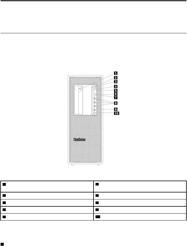
Figure 1. Front connectors, controls, and indicators |
|
|
|
1 |
Optical-drive eject/close button (available on some |
2 |
Power button |
models) |
|
|
|
3 |
Power indicator |
4 |
Storage drive activity indicator |
5 |
Signal diagnostic LED indicator |
6 |
SD card slot |
7 |
Photoelectric sensor |
8 |
USB 3.0 connectors (3) |
9 |
Always On USB 3.0 connector |
10 Headset connector |
|
Note: The orientation of the ThinkStation® logo plate on the front of your computer is adjustable. When you lay the computer on its side, you can slightly pull out the logo plate. Turn it 90-degree counterclockwise, and then push it back in.
1 Optical-drive eject/close button (available on some models)
Press the button to eject or close the tray of the optical drive.
© Copyright Lenovo 2017, 2018 |
1 |

2 Power button
Press the power button to turn on your computer. If your computer is unresponsive, you can turn off the computer by pressing and holding the power button for four or more seconds.
3 Power indicator
When the power indicator is on, the computer is turned on.
4 Storage drive activity indicator
This indicator shows the status of the internal storage drives (such as hard disk drives or solid-state drives).
On The storage drives are active: and data is being transferred.
Off (when the computer is powered on): No data is being transferred or the storage drives are not in use.
5 Signal diagnostic LED indicator
Off (when the computer is powered on): No error or issue is detected on your computer during normal operation.
On A catastrophic error is detected: on your computer during normal operation.
Blinking An error or issue is detected on your computer during normal operation. |
: |
6 SD card slot
Insert a secure digital (SD) card into the slot to access the data on the card.
7 Photoelectric sensor
This sensor receives the flash light sent by the Lenovo PC Diagnostics application installed in the smartphone. Then, the photoelectric sensor triggers the computer to send the tune of the detected error to the smartphone for users to decode the error.
8 USB 3.0 connector (3)
Use this connector to attach a USB-compatible device, such as a USB keyboard, mouse, storage drive, or printer.
9 Always On USB 3.0 connector
Use this connector to attach a USB-compatible device, such as a USB keyboard, mouse, storage drive, or printer. With the power cord connected, you can charge the connected USB device even when the computer is in hibernation mode or turned off. If the Always On USB connector function is not enabled, open the Power Manager program and enable the function. To open the Power Manager program, see “Accessing a program on your computer” on page 15. To enable the Always On USB connector, refer to the help system of the Power Manager program.
10 Headset connector
Use this connector to attach a headset to your computer.
2 P720 User Guide
Rear view
Some connectors on the rear of your computer are color-coded to help you determine where to connect the cables on your computer.
Note: The computer hardware might look slightly different from the illustration.
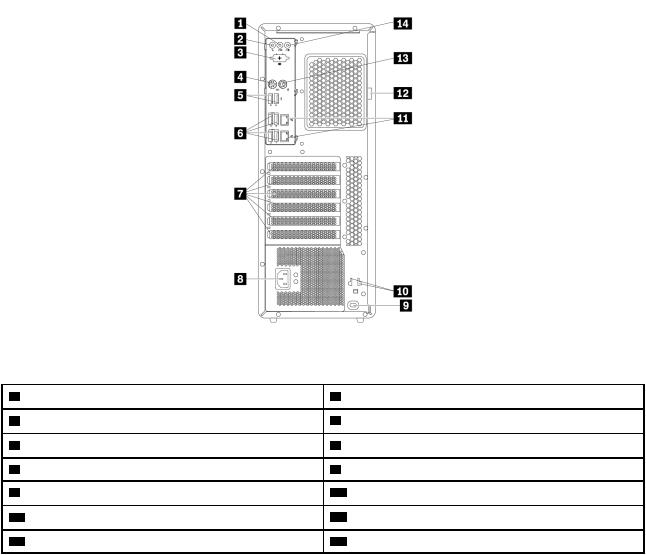
Figure 2. Rear view |
|
|
|
1 |
Audio line-out connector |
2 |
Microphone connector |
3 |
Optional serial connector |
4 |
PS/2 keyboard connector |
5 |
USB 2.0 connectors (2) |
6 |
USB 3.0 connectors (4) |
7 |
PCI/PCIe card area* |
8 |
Power-cord connector |
9 |
Security-lock slot |
10 Key-nest slots |
|
11 Ethernet connectors (2) |
12 Padlock loop |
||
13 PS/2 mouse connector |
14 Audio line-in connector |
||
Chapter 1. Product overview 3

Notes: *A discrete graphics card or a network adapter can be installed in the appropriate Peripheral Component Interconnect (PCI)/PCI-Express (PCIe) card slot. If such a card is installed, use the connectors on the card instead of the corresponding connectors on the computer to optimize the performance. Depending on your computer model, the preinstalled cards might vary. One or more graphics cards might be installed to provide the following connectors:
•Digital Visual Interface (DVI) connector
•DisplayPort® connector
•Mini DisplayPort® connector
DisplayPort connector
Use this connector to attach a high-performance monitor, a direct-drive monitor, or other compatible devices.
DVI monitor connector
Use this connector to attach a DVI monitor or other compatible devices.
Mini DisplayPort connector
Use this connector to attach a high-performance monitor, a direct-drive monitor, or other compatible devices. The Mini DisplayPort connector is a miniaturized version of a DisplayPort connector.
1 Audio line-out connector
The audio line-out connector is used to send audio signals from the computer to external devices, such as headphones.
2 Microphone connector
Use this connector to attach a microphone to your computer when you want to record sound or if you use speech-recognition software.
3 Optional serial connector
Use this connector to attach an external modem, a serial printer, or other devices that use a 9-pin serial connector.
4 PS/2 keyboard connector
Use this connector to attach a Personal System/2 (PS/2) keyboard.
5 USB 2.0 connectors (2)
Use this connector to attach a USB-compatible device, such as a USB keyboard, mouse, storage drive, or printer.
6 USB 3.0 connectors (4)
Use this connector to attach a USB-compatible device, such as a USB keyboard, mouse, storage drive, or printer.
4 P720 User Guide

7 PCI/PCIe card area
To further improve the computer performance, you can install PCI/PCIe cards into this area. Depending on your computer model, the pre-installed cards in this area might vary.
8 Power-cord connector
Connect the power cord to your computer for power supply.
9 Security-lock slot
Attach a Kensington-style cable lock to the security-lock slot to secure your computer. For more information, see “Attaching a Kensington-style cable lock” on page 33.
10 Key-nest slots
Install the key holder that comes with the computer-cover-lock key to the key-nest slots.
11 Ethernet connectors (2)
Connect an Ethernet cable for a local area network (LAN).
Note: To operate the computer within Federal Communications Commission (FCC) Class B limits, use a Category 5 Ethernet cable.
12 Padlock loop
Connect a padlock to secure your computer. For more information, see “Locking the computer cover” on page 31.
13 PS/2 mouse connector
Use this connector to attach a PS/2 mouse, a trackball, or other pointing devices.
14 Audio line-in connector
The audio line-in connector is used to receive audio signals from an external audio device, such as a stereo system. When you attach an external audio device, a cable connection is established between the audio lineout connector of the device and the audio line-in connector of the computer.
Chapter 1. Product overview 5
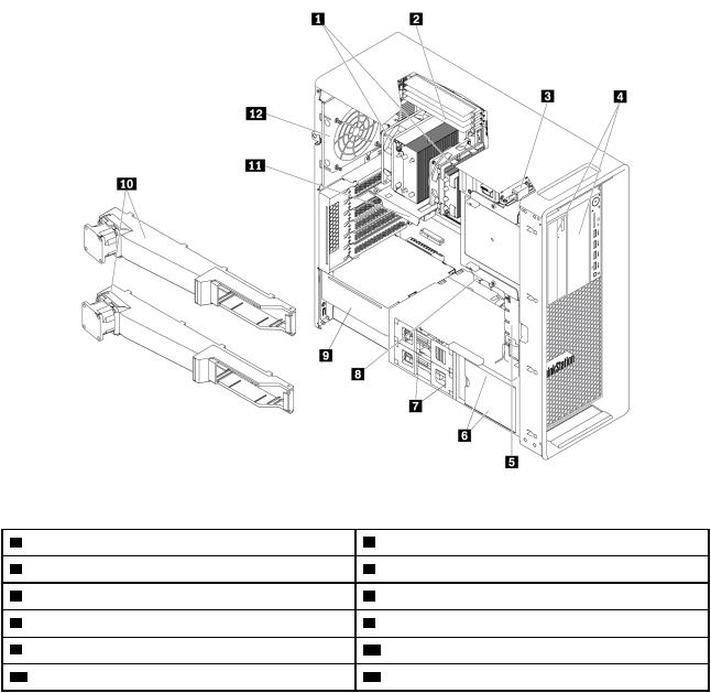
Computer components
Notes:
•Depending on the model, your computer might look slightly different from the illustration.
•To remove the computer cover, see “Preparing your computer and removing the computer cover” on page 63.
Figure 3. Component locations |
|
|
|
1 |
Heat sink and fan assemblies* |
2 |
Memory modules* |
3 |
Cover presence switch (also called intrusion switch) |
4 |
Flex bays* |
5 |
Front fan assembly |
6 |
Storage drives or a storage drive bay cover* |
7 |
Storage drives* |
8 |
M.2 solid-state drive holder |
9 |
Power supply assembly |
10 Memory air baffles |
|
11 PCI/PCIe card* |
12 Rear fan assembly |
||
*Configuration varies by computer models.
6 P720 User Guide

Parts on the system board
Note: The system board might look slightly different from the illustration.
Figure 4. System board part locations
1 Front-audio connector
3 Memory fan connector 1
5 Microprocessor 2 memory slot 5
7 Microprocessor 2 memory slot 4
9 Microprocessor 2 memory slot 2
11 Microprocessor 1 memory slot 6
13 Microprocessor 1 memory slot 3
15 Microprocessor 1 memory slot 1
17 Cover presence switch connector (intrusion switch connector)
19 Microprocessor fan connector 1
21 M.2 solid-state drive slot 1
23 VROC header
25 4-pin power connector (for optical drive)
27 Optical-drive fan connector 1
29 Optical-drive fan connector 2
2 Internal-speaker connector
4 Microprocessor 2 memory slot 1
6 Microprocessor 2 memory slot 3
8 Microprocessor 2 memory slot 6
10 Microprocessor 1 memory slot 2
12 Microprocessor 1 memory slot 4
14 Microprocessor 1 memory slot 5
16 Thermal-sensor connector
18 Microprocessor 1
20 Blind connect assembly (BCA) 3 connector
22 M.2 solid-state drive slot 2
24 Trusted cryptography module (TCM) connector
26 Four-digit-diagnostics display connector
28 Front-fan-assembly connector
30 6-pin power connector 1 (for graphics card)
Chapter 1. Product overview 7
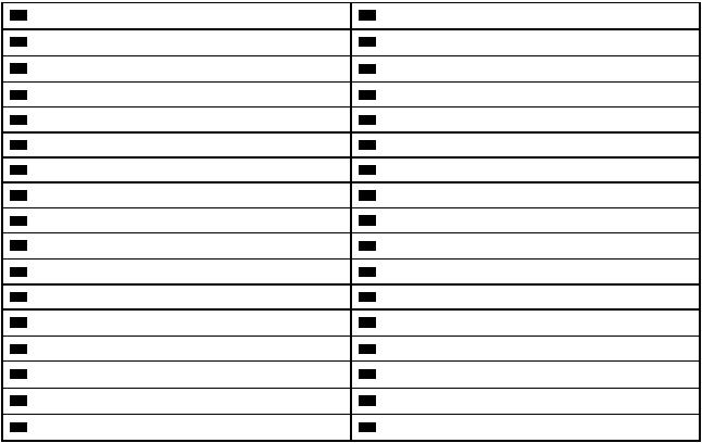
31 |
6-pin power connector 2 (for graphics card) |
33 |
4-pin power connector (for storage drive) |
35 |
Front panel connector |
37 |
BCA 1 connector |
39 |
Thunderbolt control connector |
41 |
Internal USB 2.0 connector |
43 |
Front USB 3.0 connector 1 |
45 |
SATA 4 connector |
47 |
SATA 2 connector |
49 |
Power supply connector |
51 |
eSATA/SATA connector |
53 |
PCI card slot 5 |
55 |
Clear CMOS /Recovery jumper |
57 |
PCIe 3.0 x16 card slot 2 |
59 |
Coin-cell battery |
61 |
Microprocessor 2 (available on some models) |
63 |
Serial port (COM1) connector |
8 P720 User Guide
32 |
Internal-storage-drive activity indicator connector |
|
34 |
4-pin power connector (for storage drive) |
|
36 |
BCA 2 connector |
|
38 |
SATA 6 connector |
|
40 |
Front USB 3.0 connector 2 |
™ |
42 |
USB 3.0 extended connector |
|
44 |
15-in-1 card reader connector |
|
46 |
SATA 3 connector |
|
48 |
SATA 1 connector |
|
50 |
SATA 5 connector |
|
52 |
PCIe 3.0 x4 card slot 6 |
|
54 |
PCIe 3.0 x16 card slot 4 |
|
56 |
PCIe 3.0 x8 card slot 3 |
|
58 |
PCIe 3.0 x16 card slot 1 |
|
60 |
Memory fan connector 2 |
|
62 |
Rear-fan-assembly connector |
|
64 |
Microprocessor fan connector 2 |
|
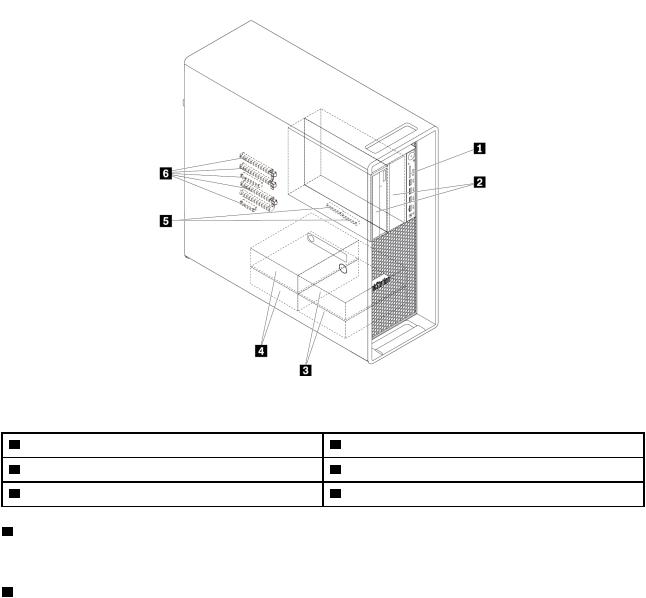
Internal storage drives
Internal storage drives are devices that your computer uses to read and store data. You can add drives to your computer to increase storage capacity and enable your computer to read other types of media. Internal storage drives are installed in bays.
When you remove or install an internal storage drive, note the type and size of the drive that each bay supports and correctly connect the required cables. Refer to the appropriate section in Chapter 7 “Hardware removal and installation” on page 63 for instructions on how to remove or install internal storage drives for your computer.
The following illustration shows the locations of the storage drive bays.
Note: The computer hardware might look slightly different from the illustration.
Figure 5. Storage drive bay locations |
|
|
|
1 |
Card reader (for an SD card) |
2 |
Flex bays (2) |
3 |
Optional-storage-drive bays (2) |
4 |
Storage drive bays (2) |
5 |
M.2 solid-state drive slots (2) |
6 |
PCIe slots (5) |
1 Card reader
An SD card is installed in some models.
2 Flex bays (2)
Depending on your computer model, the following devices might be installed in the flex bays:
Chapter 1. Product overview 9

•Flex module
Depending on your computer model, the following parts might be installed in the flex module:
–15-in-1 card reader
–External Serial Advanced Technology Attachment (eSATA) connector
–Four-digit diagnostic display
–Institute of Electrical and Electronics Engineers (IEEE) 1394 connector
–Slim optical drive
–Thunderbolt adapter kit
•Front-access storage enclosure
•Multi-drive conversion kit
Depending on your computer model, the following parts might be installed in the multi-drive conversion kit:
–Internal storage drive (such as hard disk drive, solid-state drive, or hybrid drive)
–Slim optical drive
•Optical drive
•Slim-optical-drive adapter
3 Optional-storage-drive bays (2)
You can install hard disk drives, solid-state drives, or hybrid drives in the storage drive bays.
Note: If you want to install storage drives into the 3 optional-storage-drive bays, contact the Lenovo Customer Support Center for help.
4 Storage drive bays (2)
You can install hard disk drives, solid-state drives, or hybrid drives in the storage drive bays.
5 M.2 solid-state drive slots (2)
One or two M.2 solid-state drives are installed in some models.
6 PCIe slots (5)
You can install compatible PCIe cards and PCIe solid-state drives in the PCIe card slots.
10 P720 User Guide
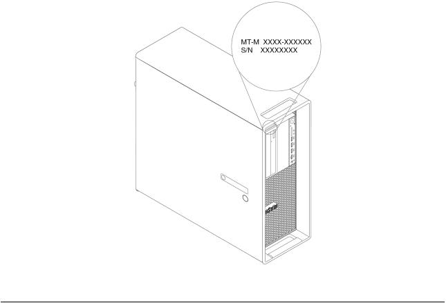
Machine type and model label
The machine type and model label identifies your computer. When you contact Lenovo for help, the machine type and model information helps support technicians to identify your computer and provide faster service.
The following is a sample of the machine type and model label.
Note: The computer hardware might look slightly different from the illustration.
Figure 6. Machine type and model label
Computer features
For your specific computer model, some features might vary or not apply.
Information about your computer
•To view basic information (such as microprocessor and memory information) about your computer, do the following:
1.Click the Start button to open the Start menu.
2.Depending on your Microsoft® Windows® operating system version, do one of the following:
– For Windows 7: Right-click Computer and then click Properties
– For Windows 10: Click Settings System About |
. |
•To view detailed information about the devices (such as the optical drive and network adapters) on your computer, do the following:
1.Depending on your Windows version, do one of the following:
–For Windows 7: Click the Start button to open the Start menu. Right-click Computer and then click Properties
Chapter 1. Product overview 11
– For Windows 10: Right-click the Start button to open the Start context menu.
2. Click Device Manager |
. |
3.Locate and double-click your device in Device Manager to view device properties. Type the administrator password or provide confirmation if prompted.
Memory
Up to 12 double data rate 4 (DDR4) error correction code (ECC) registered dual inline memory modules (RDIMMs)
Storage drives
Your computer supports the following storage drives:
•Hard disk drive
•Hybrid drive (available on some models)
•M.2 solid-state drive (available on some models)
•Optical drive (available on some models)
•SD card (available on some models)
•Solid-state drive (available on some models)
To view the amount of storage drive space, do the following:
1. Depending on your Windows version, do one of the following:
• For Windows 7: Click the Start button to open the Start menu. Right-click Computer and then click
Manage .
• For Windows 10: Right-click the Start button to open the Start context menu.
2.Click Disk Management and follow the instructions on the screen.
Video features
•PCIe 3.0 x16 card slots on the system board for a discrete graphics card
•Video connectors on a discrete graphics card:
–DVI connector (available on some models)
–DisplayPort connector (available on some models)
–Mini DisplayPort connector (available on some models)
Audio features
Integrated audio controller supports the following connectors and devices on your computer:
•Audio line-in connector
•Audio line-out connector
•Headset connector
•Internal speaker
•Microphone connector
Input/Output (I/O) features
•100/1000 Mbps Ethernet connector
•Audio connectors (audio line-in connector, audio line-out connector, microphone connector, and headset connector)
12 P720 User Guide
•Display connectors (DisplayPort connector, DVI connector, and Mini DisplayPort connector) (vary by graphics card)
•Optional 9-pin serial connector
•PS/2 keyboard connector
•PS/2 mouse connector
•USB connectors
•USB-C connector (available on some models)
Expansion
•Flex bays
•Storage drive bays
•M.2 solid-state drive slots
•Memory slots
•One PCI card slot
•One PCIe 3.0 x4 card slot
•One PCIe 3.0 x8 card slot
•Three PCIe 3.0 x16 card slots
•SD card slot
Power supply
Your computer comes with one of the following power supplies:
•690-watt automatic voltage-sensing power supply
•900-watt automatic voltage-sensing power supply
Wireless features
Depending on your computer model, the following wireless features are supported:
•Wireless LAN
•Bluetooth
System management features
•Ability to store power-on self-test (POST) hardware test results
•Desktop Management Interface (DMI)
Desktop Management Interface provides a common path for users to access information about all aspects of a computer. The information includes the processor type, installation date, attached printers and other peripherals, power sources, and maintenance history.
•ErP LPS compliance mode
The energy-related products directive (ErP) lowest power state (LPS) compliance mode reduces the consumption of electricity when your computer is in sleep or off mode. For more information, see “Enabling or disabling the ErP LPS compliance mode” on page 38.
•Intel® Standard Manageability (ISM)
Intel Standard Manageability builds certain functionalities into computer hardware and firmware. Therefore, computers are less expensive for businesses and easier to monitor, maintain, update, upgrade, and repair.
Chapter 1. Product overview 13
•Intel Active Management Technology (Intel AMT)
With specific Intel platform capabilities and third-party management and security applications, Intel Active Management Technology enables IT administrators or managed service providers to easily and remotely discover, repair, and protect their networked computing assets.
•Intel Rapid Storage Technology enterprise (Intel RSTe)
The Intel RSTe configuration utility enables you to configure Redundant Array of Independent Disks (RAID) for computers with specific Intel chipset system boards. It supports RAID levels 0, 1, 5, and 10 on computers installed with Serial Advanced Technology Attachment (SATA) devices.
•Preboot Execution Environment (PXE)
Preboot Execution Environment enables you to start computers using a network interface. This manner is independent of starting computers from data storage devices (such as the hard disk drive) or installed operating systems.
•System Management (SM) basic input/output system (BIOS) and SM software
The SMBIOS specification defines data structures and access methods in a BIOS. Therefore, a user or an application can store and retrieve information specific about the computer in question.
•Wake on LAN (WOL)
Wake on LAN is an Ethernet computer networking standard that allows a computer to be turned on or woken up by a network message. The message is usually sent by a program running on another computer on the same local area network.
•Windows Management Instrumentation (WMI)
Windows Management Instrumentation is a set of extensions to the Windows Driver Model. It provides an operating system interface through which instrumented components provide information and notification.
Security features
•Ability to enable and disable a device
•Ability to enable and disable USB connectors individually
•Antivirus program
•BIOS passwords and Windows accounts to deter unauthorized use of your computer
•Computrace Agent software embedded in firmware
•Cover presence switch (also called intrusion switch)
•Finger authentication (available on some models)
•Firewalls
•Intel BIOS guard
•Smart USB Protection function
•Startup sequence control
•Startup without a keyboard or mouse
•Support for a key lock on the computer cover (available on some models)
•Support for a Kensington-style cable lock
•Support for a padlock
•Trusted Platform Module (TPM)
Preinstalled operating system
Your computer is preinstalled with Windows 7 or Windows 10 operating system. Additional operating systems might be identified by Lenovo as compatible with your computer. To determine if an operating system has been certified or tested for compatibility, check the Web site of the operating system provider.
14 P720 User Guide

Computer specifications
This section lists the physical specifications for your computer.
Dimensions
•Width: 175 mm (6.89 inches)
•Height: 446 mm (17.56 inches)
•Depth: 485 mm (19.09 inches)
Weight
Maximum configuration as shipped: 24 kg (52.91 lb)
Environment
• Air temperature:
Operating: From 10°C (50°F) to 35°C (95°F)
Storage in original shipping package: From -40°C (-40°F) to 60°C (140°F)
Storage without package: From -10°C (14°F) to 60°C (140°F)
• Humidity:
Operating: 10%–80% (non-condensing)
Storage: 10%–90% (non-condensing)
• Altitude:
Operating: From -15.2 m (-50 ft) to 3048 m (10 000 ft)
Storage: From -15.2 m (-50 ft) to 10 668 m (35 000 ft)
Electrical input
•Input voltage: From 100 V ac to 240 V ac
•Input frequency: 50/60 Hz
Programs
This section provides information about the programs on your computer.
Accessing a program on your computer
Note: For Windows 7, depending on your computer model, some of the Lenovo programs might be ready to be installed, so you must install them manually. Then, you can access and use these programs.
To access a program on your computer, do one of the following:
•From Windows Search:
1.Depending on your Windows version, do one of the following:
–For Windows 7: Click the Start button to open the Start menu, and then type the program name into the search box.
–For Windows 10: Type the program name into the search box next to the Start button.
2.In the search results, click the name of the desired program to launch the program.
•From the Start menu or Control Panel:
Chapter 1. Product overview 15
1.Depending on your Windows version, do one of the following:
–For Windows 7: Click the Start button to open the Start menu. If the program name is not displayed, click All Programs to display the program list. Then, click the name of the desired program to launch the program.
–For Windows 10: Click the Start button to open the Start menu. Then, click the name of the desired program to launch the program.
2.If the program name is not displayed on the Start menu, access the program from Control Panel. a. Click the Start button to open the Start menu.
b. Depending on your Windows version, do one of the following:
– For Windows 7: Click Control Panel |
. |
– For Windows 10: Click Windows System Control Panel
c.View Control Panel by Large icons or Small icons, and then click the name of the desired program to launch the program.
Installing a program that is ready to be installed (Windows 7 only)
On the Windows 7 operating system, to install a program that is ready to be installed, do the following:
1.Open the Lenovo ThinkVantage® Tools program. See “Accessing a program on your computer” on page 15.
2.Click View Tiles to view the program icons.
3.Follow the instructions under grayed-out icons to locate the icon for the desired program. Then, doubleclick the icon to install the program.
An introduction to Lenovo programs
This section provides information about the major Lenovo programs available on your operating system.
Note: Depending on your computer model, some of the following programs might not be available.
•Fingerprint Manager Pro or ThinkVantage Fingerprint Software (Windows 7)
The Fingerprint Manager Pro or ThinkVantage Fingerprint Software program enables you to use a fingerprint reader. The integrated fingerprint reader provided on some keyboards enables you to enroll your fingerprint and associate it with your power-on password, hard disk password, and Windows password. As a result, fingerprint authentication can replace passwords and enable simple and secure user access.
16 P720 User Guide
Loading...