

Page 1

Leica M525 OH4
User manual
10 714 367 – version -
Page 2

Leica M525 OH4 / Ref. 10 714 367 / Version -
Thank you for purchasing a Leica surgical microscope system.
In developing our systems, we have placed great emphasis on
simple, self-explanatory operation. Nevertheless, we suggest
studying this user manual in detail in order to utilize all the benefits of your new surgical microscope.
For valuable information about Leica Microsystems products
and services, and the address of your nearest Leica representative, please visit our website,
www.leica-microsystems.com
Thank you for choosing our products. We hope that you will
enjoy the quality and performance of your Leica Microsystems
surgical microscope.
Leica Microsystems (Schweiz) AG
Surgical Microscopy Business Unit
Page 3

Chapter overview
Leica M525 OH4 / Ref. 10 714 367 / Version -
Introduction 3
Controls 6
Preparation for operation 21
Use 37
Safety notes 58
Care and maintenance 68
What to do if...? 73
Technical data 77
1
Page 4

Contents
Leica M525 OH4 / Ref. 10 714 367 / Version -
screen
Introduction
User manual 3
Product identification 3
Symbols in this user manual 3
Design 4
Controls
Leica M525 microscope with swing arm 6
Control unit 7
Terminals 7
Stand 8
CAN handles 9
Mouth switch 9
Footswitch 9
Beam splitter 17
Beam splitter with counterweight 17
180° assistant’s attachment 17
Ultra Observer Leica ULT500 17
Dual Imaging Color Module Leica DI C500 18
Stereoscopic co-observer tube 18
Tubes 18
Video and photo accessories for Leica M525 20
Preparation for operation
Checklist: before the operation 21
Installing optical accessories 22
Setting the tube 23
Setting the eyepiece 24
Installing documentation accessories 24
Selecting documentation accessories 26
Stand settings 27
Changing the weight disk on the D-axis 33
Releasing the brakes 34
Transport, transporting and rest positions 35
Positioning on the operating table 36
Attaching sterile controls 36
Use
Positioning the microscope 37
Adjusting the microscope 38
Control unit with touch panel 43
Leica DI C500 52
Autofocus settings 54
The Maintenance menu 56
Microscope settings 57
The "How to..." menu 57
The Service menu 57
2
screen
Safety notes
Intended use 58
Directions for the person responsible for the
instrument 58
Directions for the operator of the instrument 59
Dangers of use 60
Manufacturer's declaration of electromagnetic
compatibility (EMC) 62
Signs and labels 66
Care and maintenance
Maintenance instructions 68
Cleaning the touch panel 68
Maintenance 68
Changing bulbs 69
Checking the timer for the xenon lamp 69
Changing fuses 70
Notes on reprocessing of
resterilizable products 71
Instructions 71
What to do if...?
General faults 73
TV, photography 75
Error messages on the control unit 76
Technical data
Electrical data 77
Leica M525 77
Accessories 77
IGS 78
Fluorescence 78
Floor stand 78
Ambient conditions 79
Standards fulfilled 79
Limitations of use 79
List of weights of balanceable configurations 80
Dimensional drawings 81
Page 5

Introduction
Leica M525 OH4 / Ref. 10 714 367 / Version -
User manual
In addition to instructions for use, this user
manual also provides important safety notes (see
the chapter entitled, "Safety notes").
Read the user manual carefully and thoroughly
before placing the product in operation.
Product identification
The model code and serial number of your product are provided
on the nameplate found on the illumination unit. Write this data
into your user manual and always refer to it when you contact
us or the service workshop regarding any questions you may
have.
Model: Serial No.:
Symbols in this user manual
The symbols used in this user manual have the following
meanings:
Warning Warning regarding use hazard or
improper use which can cause serious
personal injury or death.
Caution Warning regarding use hazard or
improper use which can cause minor personal injury, but considerable damage to
property, assets and the environment.
Useful information that can help the user
operate the product correctly and
efficiently.
Call to action; here you are asked to do something.
➩
3
Page 6

Introduction
4
Leica M525 OH4 / Ref. 10 714 367 / Version -
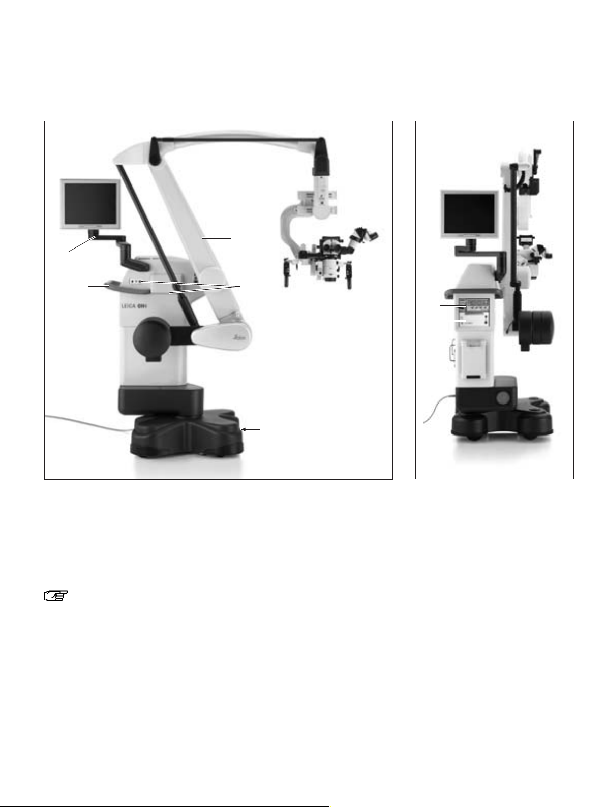
Design
surgical microscope Leica M525 OH4
1 Swing arm
2 Tiebar
3 Video monitor (optional)
4 Control unit with touch panel
5 Suspension device for footswitch
6 Illumination unit
7 Base
8 Optical carrier Leica M525
1
2
3
4
6
8
5
7
Page 7
Introduction
5
Leica M525 OH4 / Ref. 10 714 367 / Version -
1 Vertical arm
2 Terminals
3 Footbrake
4 Handle
5 Articulated arm for monitor
6 Camera control unit (optional)
7 System unit Leica MDRS3 (optional)
The Leica M525 with its open architecture, offers space for accommodating the video control unit and the Leica MDRS3.
4
3
1
2
5
6
7
Page 8

Controls
6
Leica M525 OH4 / Ref. 10 714 367 / Version -
Microscope Leica M525 with swing arm
1 Status LED for fluorescence
- LED lights up white = white light mode
- LED lights up blue = blue light mode
- LED lights up yellow = NIR mode
- LED lights up green = Playback mode
2 Status LED for recording LED lights up red = recording in
progress
3 Push-button for intraoperative AC/BC balancing
4 Switch for manual balancing of the C-carriage
5 C-carriage
6 CAN handle
7 Display of set working distance
8 Optical carrier M525
9 Switch for manual balancing of the A-carriage
10 A-carriage
11 CAN handle clamping lever
12 Switch for manual balancing of the B-carriage
13 B-carriage
14 Swing mount
1
2
3
4
5
6
789106
11
12 13
14
15 CAN socket for accessories (DI C500, FL400)
16 CAN socket (not used)
17 Optical fiber
18 Rotary button for zoom adjustment
19 Rotary button for illumination field diameter adjustment
20 Reset button for zoom dependent illumination field diameter
adjustment
21 Status of multifocus LED
22 Multifocus key
23 Rotary button for focus adjustment
24 Working distance display
18
19
20
21
22
24
23
15
16
17
Page 9
Controls
7
Leica M525 OH4 / Ref. 10 714 367 / Version -
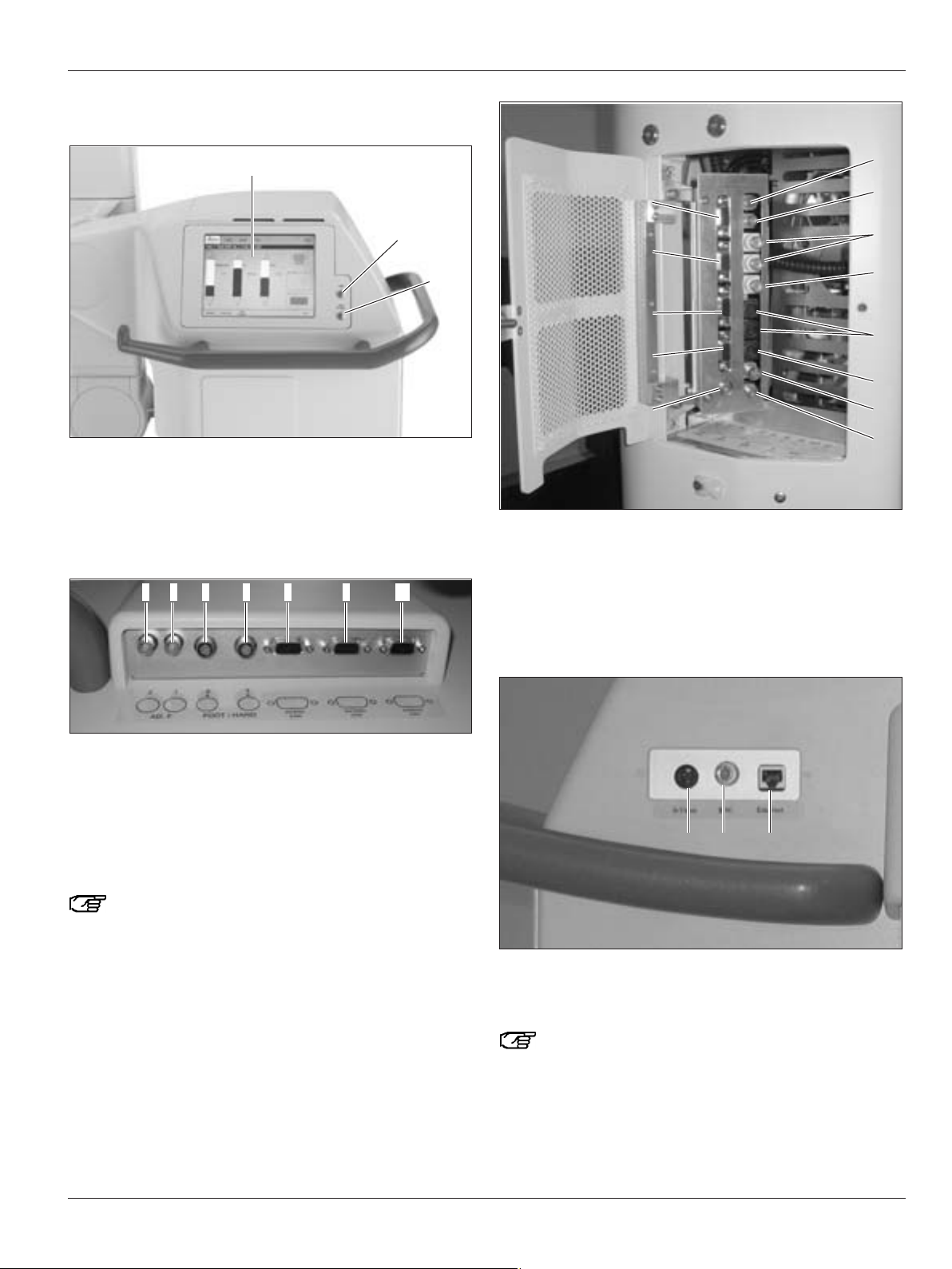
Control unit
1 Touch panel
2 Push-button with illumination LED (on/off)
3 Push-button with LED for Auto Balance
Terminals
4 AD.F. Additional Function 2
5 AD.F. Additional Function 1
6 Footswitch or handswitch 2
7 Footswitch or handswitch 1
8 Internal CAN
9 External CAN
10 External CAN
AD.F. 1 and 2 are digital relay outputs that can switch
24V/2A.
4 8 9 105 6 7
1
2
3
11 Storz light source 18 for Sony NIR camera
12 UV camera Hitachi 19 Leica MDRS3
13 BNC IN (2x) 20 SVGA IN 3
14 BNC OUT 21 SVGA IN 2
15 S-Video IN (2x) 22 SVGA IN 1
16 S-Video OUT 23 SVGA OUT to Leica DI C500
17 Storz footswitch
24 S-Video adapter
25 BNC adapter
26 Ethernet adapter
Terminals 24, 25 and 26 are adapters which can be
used to lead out the terminals of the optional
Leica MDRS3 system unit or a camera control.
24 25 26
12
13
14
15
16
17
18
19
20
21
22
23
11
Page 10
Controls
Leica M525 OH4 / Ref. 10 714 367 / Version -8
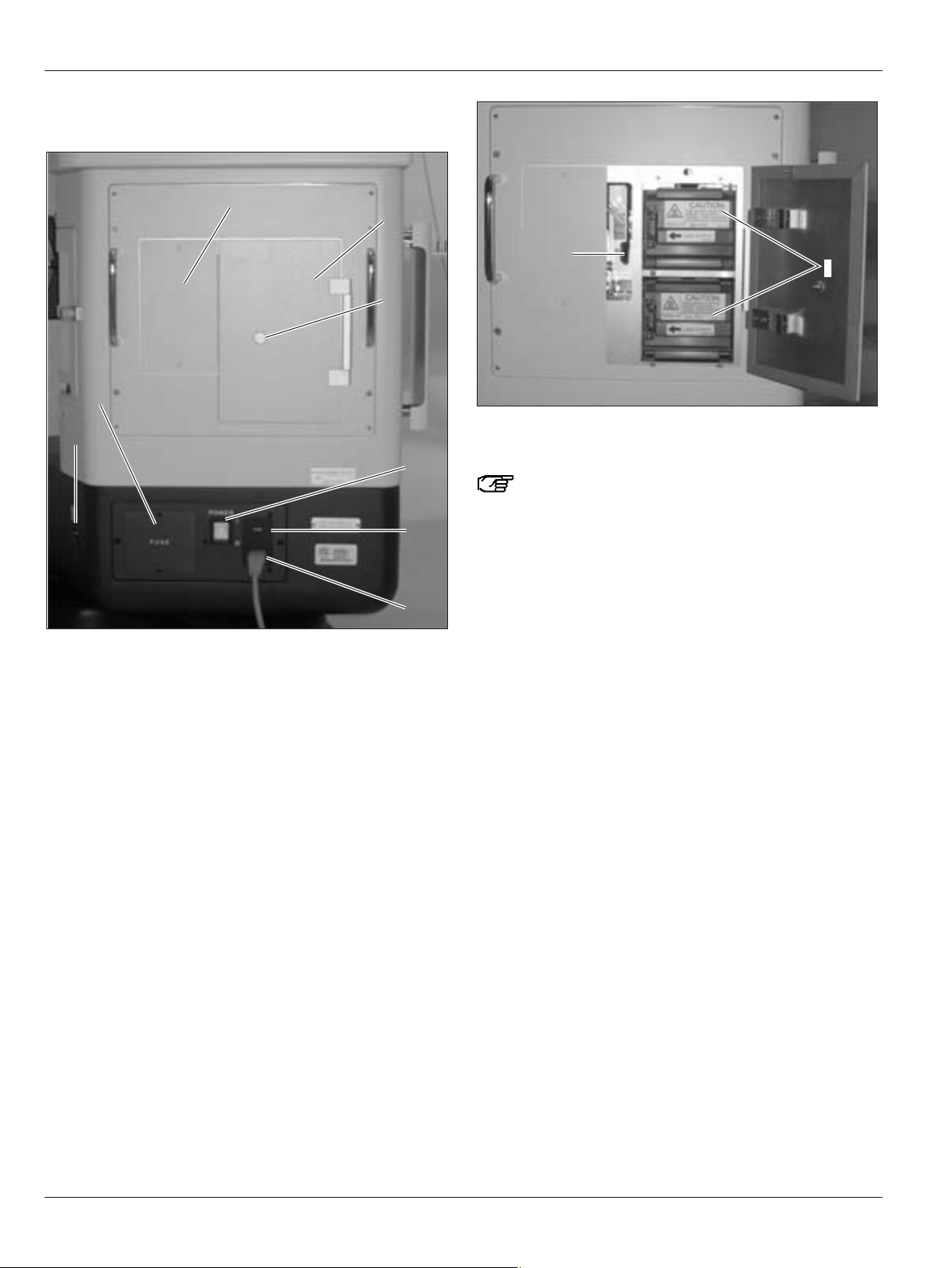
Stand
1 Illumination unit
2 Access door
3 Screw knob
4 Master switch for Leica M525 OH4 surgical microscope
5 Selector switch 100V/120V/220V/240V
6 Power supply
7 Potential equalization socket
8 Fuse box flap
4
5
6
7
8
1
2
3
9 Lamp inserts for main illumination or backup illumination
10 Lever for switching to standby illumination
The Leica M525 OH4 surgical microscope has a
primary illumination source and an equivalent standby
illumination source.
10
9
Page 11

Controls
9
Leica M525 OH4 / Ref. 10 714 367 / Version -
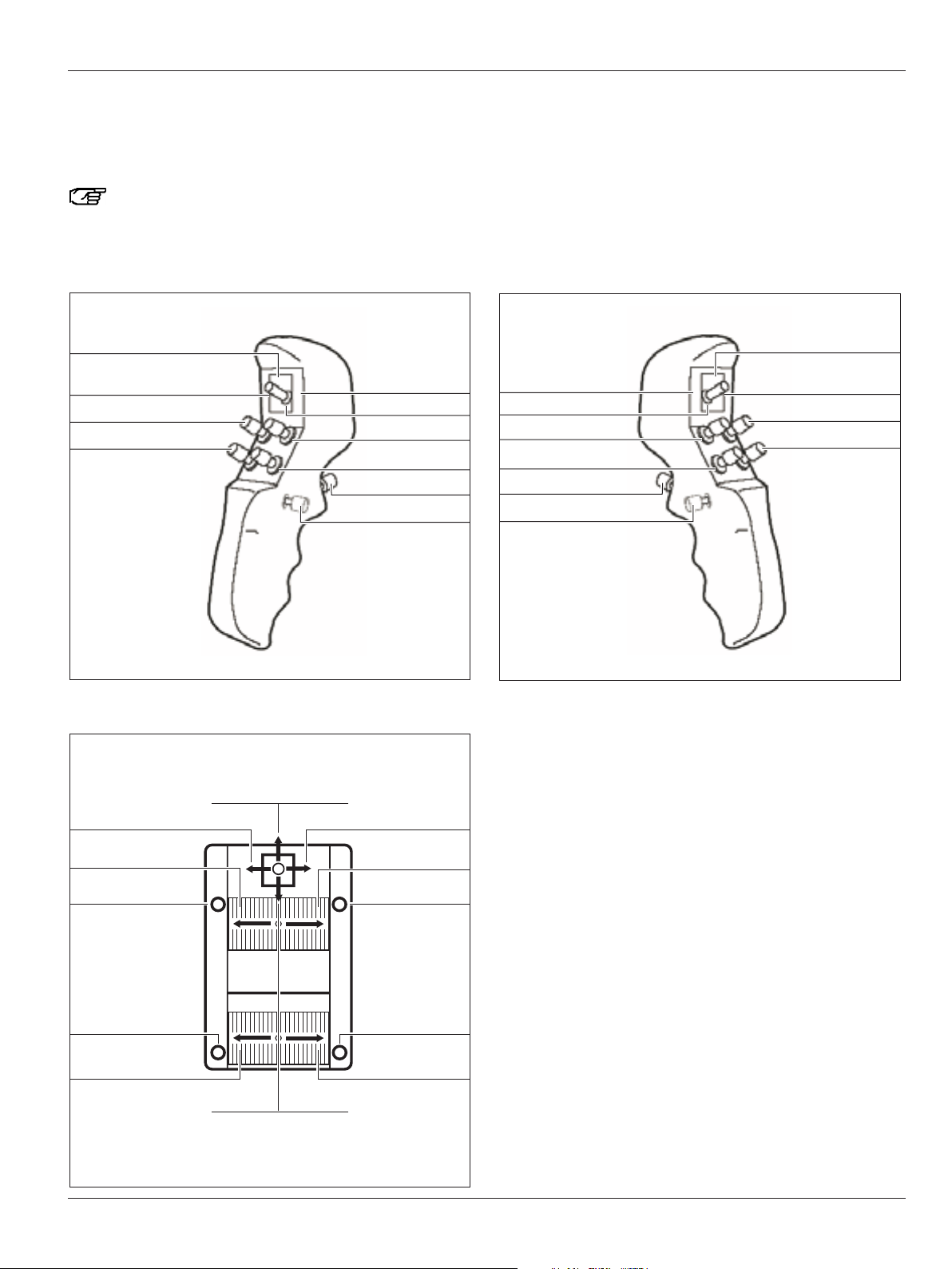
CAN handles
1 Zoom
2 4-function joystick
3 Focus
4 Release All Brakes
5 Release preselected brakes
1
2
4
3
5
Mouth switch
6 Release preselected brakes
6
You can assign switches 1, 2, 3 and 5 of the CAN handles individually for each user in the configuration menu
(see page 50).
Footswitch
Here you will find an overview of the footswitches which you can use to control your Leica M525 surgical microscope.
Footswitches can be assigned individually for each user in the configuration menu (see page 48).
Footswitch Footswitch Footswitch Footswitch
12 functions crosswise 16 functions crosswise 12 functions lengthwise 16 functions lengthwise
Page 12

Controls
10
Leica M525 OH4 / Ref. 10 714 367 / Version -
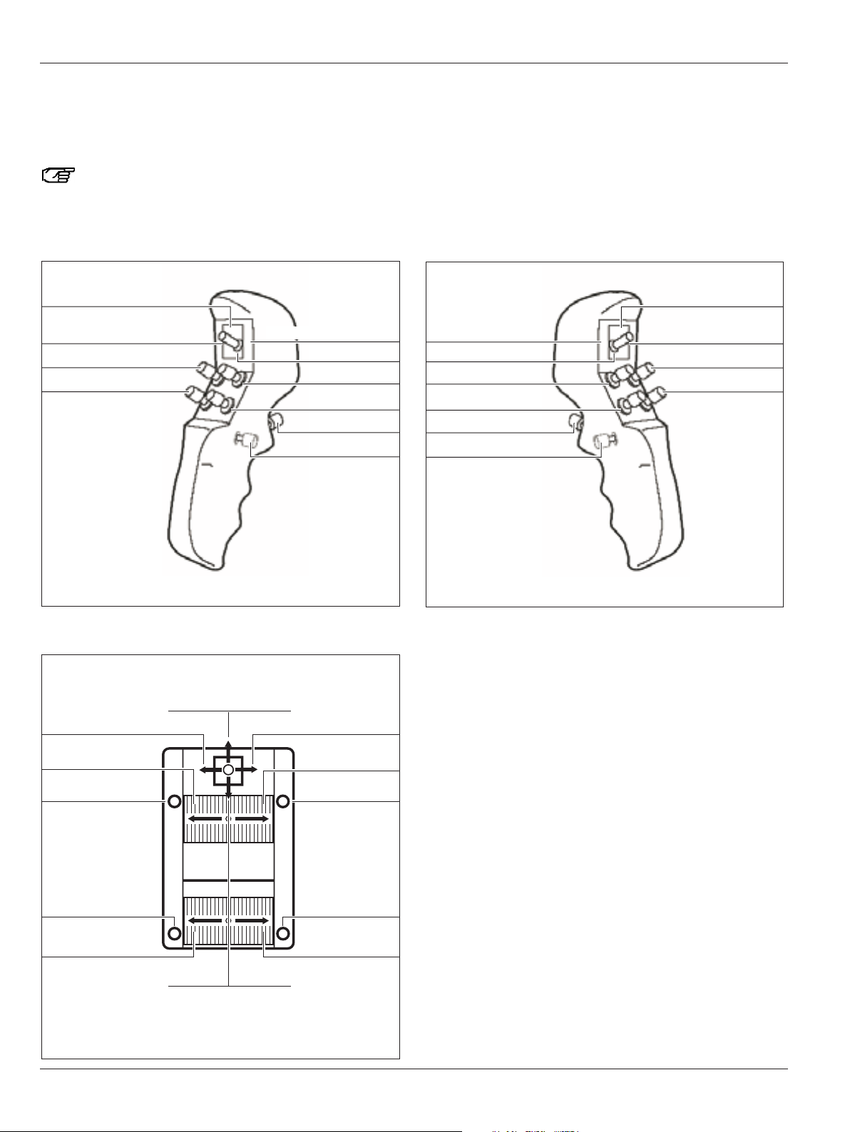
Presets "Cranial"/"Spine"/"ENT"
Here you will find an overview of the assignments of the CAN
handles and an optionally connected footswitch for the preset
user "Cranial"/"Spine"/"ENT".
You can assign CAN handles and footswitches
individually for each user in the configuration menu
(see pages 48 and 50).
Y+
Focus +
Y-
X+
Zoom +
X-
Zoom -
Focus -
All Brakes
Selected brakes
Y+
X+
Y-
Zoom +
X-
No function
Focus -
Focus +
No function
No function
Zoom -
Y+
X-
Y-
Focus +
Focus -
All Brakes
Selected brakes
X+
Zoom +
Zoom -
No function
Page 13
Controls
11
Leica M525 OH4 / Ref. 10 714 367 / Version -
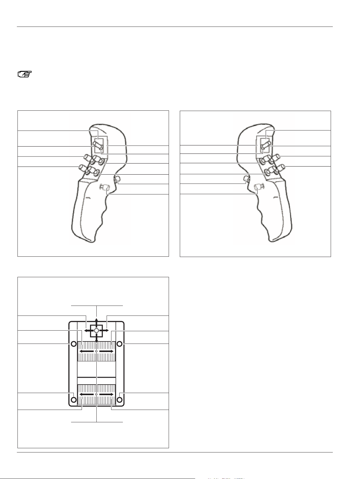
Preset "Image Injection IGS DI C500"
Here you will find an overview of the assignments of the CAN
handles and an optionally connected footswitch for the preset
user "Image Injection IGS DI C500".
You can assign CAN handles and footswitches
individually for each user in the configuration menu
(see pages 48 and 50).
IGS 3
Focus +
Zoom +
Zoom -
Focus -
All Brakes
Selected brakes
Y+
X+
Y-
Zoom +
X-
IGS 3
Focus -
Focus +
IGS 2
IGS 1
IGS 4
Zoom -
Y+
XY-
Focus +
Focus -
All Brakes
Selected brakes
X+
Zoom +
Zoom -
IGS 4
IGS 2
IGS 1
Page 14
Controls
12
Leica M525 OH4 / Ref. 10 714 367 / Version -
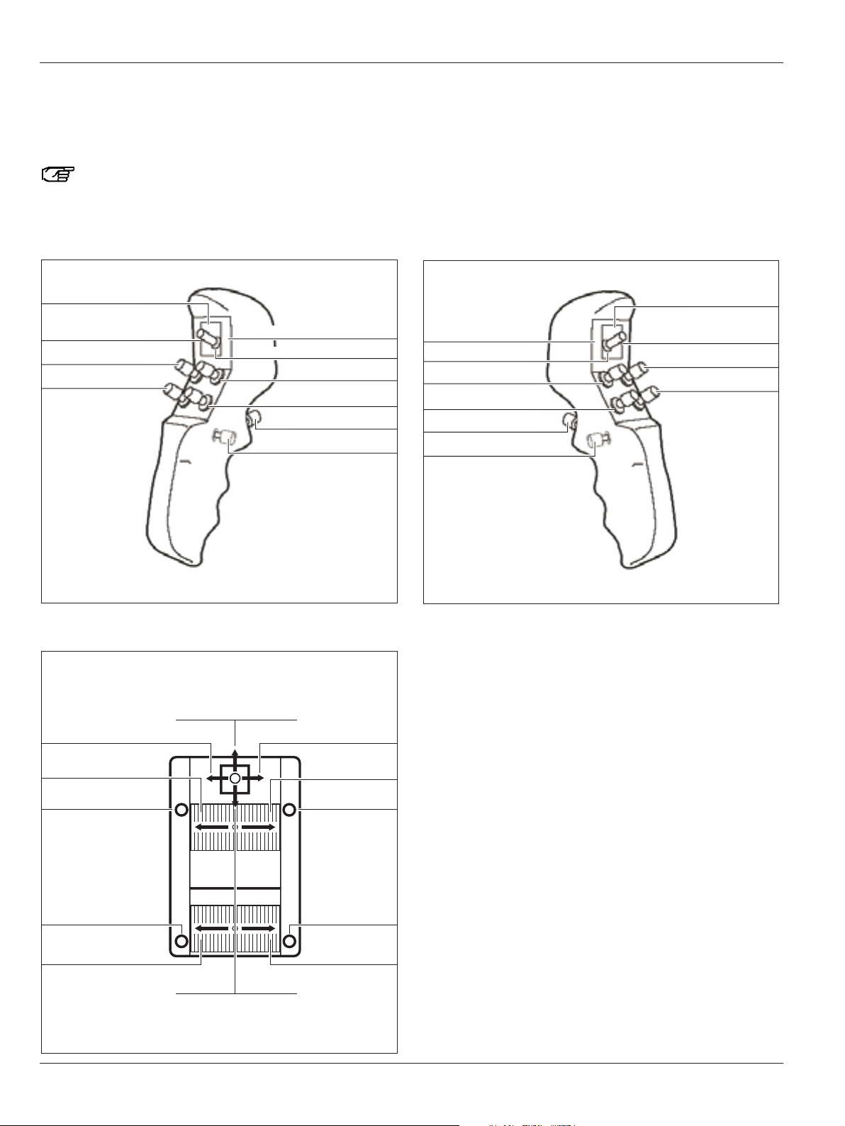
Preset "Image Injection ENDO DI C500"
Here you will find an overview of the assignments of the CAN
handles and an optionally connected footswitch for the preset
user "Image Injection ENDO DI C500".
You can assign CAN handles and footswitches
individually for each user in the configuration menu
(see pages 48 and 50).
No function
Focus +
DI C500:Shutter control
Zoom +
DI C500: Display on/off
Zoom -
Focus -
All Brakes
Selected brakes
Y+
X+
Y-
Zoom +
X-
DI C500:
Display on/off
Focus -
Focus +
No function
No function
Zoom -
Y+
XY-
Focus +
Focus -
All Brakes
Selected brakes
X+
Zoom +
Zoom -
No function
DI C500:
Shutter control
Page 15

Controls
13
Leica M525 OH4 / Ref. 10 714 367 / Version -
Preset "Fluorescence Vascular FL800"
Here you will find an overview of the assignments of the CAN
handles and an optionally connected footswitch for the preset
user "Fluorescence Vascular FL800".
You can assign CAN handles and footswitches
individually for each user in the configuration menu
(see pages 48 and 50).
FL800 NIR Zoom Reset
Focus +
Zoom +
FL800 Mode on/off
Zoom -
Focus -
All Brakes
Selected brakes
Y+
X+
Y-
Zoom +
X-
Focus -
Focus +
Zoom -
MDRS3 FL:Menu&Down
FL800 Mode on/off
FL800 NIR
Zoom Reset
MDRS3 FL:Menu&Down
MDRS3 FL:
Playback&Enter
MDRS3 FL: Playback&Enter
Y+
XY-
Focus +
Focus -
All Brakes
Selected brakes
X+
Zoom +
Zoom -
Page 16
Controls
14
Leica M525 OH4 / Ref. 10 714 367 / Version -
Preset "Fluorescence Oncology FL400"
Here you will find an overview of the assignments of the CAN
handles and an optionally connected footswitch for the preset
user "Fluorescence Oncology FL400".
You can assign CAN handles and footswitches
individually for each user in the configuration menu
(see pages 48 and 50).
No function
Focus +
Zoom +
FL400 Mode on/off
Zoom -
Focus -
All Brakes
Selected brakes
Y+
X+
Y-
Zoom +
X-
Focus -
Focus +
No function
No function
Zoom -
No function
No function
FL400 Mode on/off
No function
Y+
XY-
Focus +
Focus -
All Brakes
Selected brakes
X+
Zoom +
Zoom -
Page 17

Controls
15
Leica M525 OH4 / Ref. 10 714 367 / Version -
Preset "Fluorescence Oncology FL400 & IGS DI C500"
Here you will find an overview of the assignments of the CAN
handles and an optionally connected footswitch for the preset
user "Fluorescence Oncology FL400 & IGS DI C500".
You can assign CAN handles and footswitches
individually for each user in the configuration menu
(see pages 48 and 50).
IGS 3
Focus +
Zoom +
IGS 4
Zoom -
Focus -
All Brakes
IGS 3
Zoom +
Focus -
Focus +
No function
No function
Zoom -
IGS 1
IGS 2
FL400 Mode on/off
No function
IGS 4
IGS 2
IGS 1
Y+
XY-
Focus +
Focus -
All Brakes
Selected brakes
X+
Zoom +
Zoom -
FL400 Mode on/off
Page 18
Controls
16
Leica M525 OH4 / Ref. 10 714 367 / Version -
Preset "Fluorescence Oncology FL400 & Vascular FL800"
Here you will find an overview of the assignments of the CAN
handles and an optionally connected footswitch for the preset
user "Fluorescence Oncology FL400 & Vascular FL800".
You can assign CAN handles and footswitches
individually for each user in the configuration menu
(see pages 48 and 50).
FL800 NIR Zoom Reset
Focus +
Zoom +
FL800 Mode on/off
Zoom -
Focus -
All Brakes
FL400 Mode on/off
Zoom +
Focus -
Focus +
No function
No function
Zoom -
MDRS3 FL: Menu&Down
MDRS3 FL: Playback&Enter
FL400 Mode on/off
No function
FL800 NIR Zoom Reset
MDRS3 FL: Playback&Enter
MDRS3 FL: Menu&Down
FL400 Mode on/off
Y+
XY-
Focus +
Focus -
All Brakes
Selected brakes
X+
Zoom +
Zoom -
Page 19

Controls
17
Leica M525 OH4 / Ref. 10 714 367 / Version -
A comprehensive range of accessories enables the
Leica M525 OH4 surgical microscope to be matched to the
requirements of the task in hand. Your Leica representative will
be pleased to help you select the appropriate accessories.
Beam splitter
• Can be used for co-observation or documentation
Light distribution: 50% on each side (mono) or 30% / 70%
Beam splitter with counterweight
• Can be used for co-observation or documentation
Light distribution: 50% on each side (mono)
180° second observer attachment
• Allows a second observer to view the procedure
Ultra Observer Leica ULT500
• Beam splitter with eight optical ports
• Light distribution:
Surgeon (front) 40% (stereo)
Assistant (rear) 40% (stereo) or
Assistant (side) 40% (mono)
Documentation (side) 20%
VIDEO
ULT 500LEICA
Page 20
Controls
18
Leica M525 OH4 / Ref. 10 714 367 / Version -
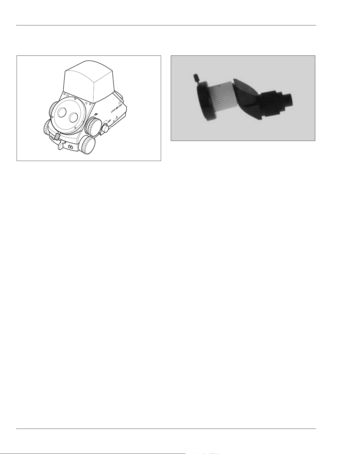
Dual Imaging Color Module Leica DI C500
• Beam splitter with eight optical ports
• Integrated color display shows data or video images.
• Light distribution:
Surgeon (front) 40% (stereo)
Assistant (rear) 40% (stereo) or
Assistant (side) 40% (mono)
Documentation (side) 20%
VIDEO
Stereo attachment for second observer
• Is attached to the side outputs of a beam splitter.
Page 21

Controls
19
Leica M525 OH4 / Ref. 10 714 367 / Version -
Tubes
Binocular tube variable from 30°–150°
• Variable viewing angles from 30° to 150°
• Adjustable viewing height
• Adjustable interpupillary distance
Binocular tube variable from 0°–180°
• Variable viewing angles from 0° to 180°
Inclined binocular tube
Straight binocular tube
Inclined binocular tube 45°
Page 22

Controls
20
Leica M525 OH4 / Ref. 10 714 367 / Version -
Video and photo accessories for Leica M525
1 Leica 2D Pick up
2 Photo/TV dual attachment
3 Photo camera
4 TV attachment
Leica 2D pick-up
• Video system for recording 2D video sequences.
Leica 2D C-Mount
• Video system for recording 2D video sequences.
• The camera (8) is mounted on the TV attachment or Zoom
Video Adapter.
Photo/TV dual attachment
• For using a video camera with C-mount at the same time as
an SLR camera.
Complete with adapters.
• Position of video camera engageable in 45° increments.
• Video port with incorporated brightness adjustment
(3 positions).
5 Zoom Video Adapter
6 Phototube
7 Video camera (such as the Leica D2D V3)
8 Leica 2D C-Mount
TV attachment
• For commercially-available video cameras with C-mount,
complete with adapter.
• The TV attachment (4) is installed at the documentation port
of the 0° assistant’s attachment.
• Position of video camera engageable in 90° increments.
Zoom Video Adapter
• For commercially-available video cameras with C-mount,
complete with adapter.
• The Zoom Video Adapter (5) is installed at the documentation
port of the 0° assistant’s attachment.
• Zoom and fine focus function for Leica Zoom Video Adapter
Phototube
• Complete with adapter, for SLR cameras.
• Adapter f = 250mm: for large fields of view and short expo-
sure times.
• Adapter f = 350mm: for high magnifications.
• The phototube (6) is mounted on the documentation port of
the 0° assistant’s attachment.
2
8 8
4
7
3
56
1 3
Page 23

Preparation for operation
21
Leica M525 OH4 / Ref. 10 714 367 / Version -
Checklist: Before the operation
Cleaning the optical accessories
➩Check the tubes, eyepieces and the documentation
accessories (if used) for cleanliness.
➩Remove dust and dirt (see page 68).
Installing accessories
➩Lock the Leica M525 OH4 in place and install all accessories
on the microscope so it is ready for use (see page 22).
➩Position the CAN handles as required.
➩Connect a mouth switch and/or footswitch (if used).
➩Check the camera image on the monitor and realign if
necessary.
Checking tube settings
➩Check the tube and eyepiece setting for the selected user
(see page 24).
➩Treat the eyepieces with an antifogging compound if
necessary.
Balancing
➩Balancing the Leica M525 OH4 (see page 27).
➩Press the "All Brakes" button on the CAN handle and check
the balancing.
Function check
Warning 1
Danger of fatal electrical shock.
➩The Leica M525 OH4 surgical microscope may be
connected to a grounded socket only.
➩Connect the power cable.
➩Switch on the microscope.
➩Switch on the illumination at the control unit.
Leave the illumination on for at least 5 minutes, as
otherwise luminosity will decrease rapidly.
➩Replace defective bulbs before the operation begins.
➩Test all functions on the CAN handles and on the footswitch.
➩Check the user settings on the control unit for the selected
user (see page 45).
Positioning at the OP table
➩Position the surgical microscope on the OP table as required,
and lock the footbrake (see page 35).
Sterility
➩Fit sterile components and sterile drape if used (see page 36).
Warning 2
Danger of fatal electric shock
➩Operate the system only with all equipment in its
proper position (all covers fitted, doors closed).
Page 24

Preparation for operation
22
Leica M525 OH4 / Ref. 10 714 367 / Version -
Installing optical accessories
Warning 3
Risk of injury through surgical microscope moving
down!
➩Complete all preparations and adjustments to the
stand before the operation.
➩Never balance or re-equip the instrument over the
field of operation.
➩Always lock the Leica M525 OH4 in position before re-
equipping it.
➩Balance the Leica M525 OH4 after re-equipping it.
➩Do not release the brakes when the instrument is in an
unbalanced state.
Locking the Leica M525 OH4 in position
The D-axis of the Leica M525 OH4 is locked in position with the
locking device.
The locking device is principally for installation and
re-equipping the Leica M525 OH4.
➩Pull out the locking buttons (1 and 2) and turn them until the
two points (arrows) are aligned above each another.
➩Move the swing arm up and down until locking device (1)
engages.
➩Move the swing arm back and forth until locking device (2)
engages.
1
2
Installing the 90° stereo attachment, binocular tube and beam
splitter
➩Release the clamping screw (3).
➩Insert the accessories into the dovetail ring from above.
➩Tighten the clamping screw (3).
Installing the stereo attachment for second observer
➩Insert the stereo attachment and check whether the
connection has engaged.
➩Tighten the locknut (4) by hand.
➩Align the attachment for second observer as required.
4
3
Page 25

Preparation for operation
23
Leica M525 OH4 / Ref. 10 714 367 / Version -
Setting the tube
Set the interpupillary distance
Adjust the interpupillary distance to a value between 55mm and
75mm.
➩Using the adjusting wheel (1), set the interpupillary distance
such that a circular image field can be seen.
This procedure has to be performed only once for each user.
The acquired value (2) can be stored for each user on the "User
Settings" menu screen under "Tube Settings" (see page 51).
Adjusting the tilt
➩Hold the tube with both hands.
➩Tilt the tube up or down.
2
1
Page 26

Preparation for operation
24
Leica M525 OH4 / Ref. 10 714 367 / Version -
Setting the eyepiece
Determine/set the diopters for the user
The individual diopters can be adjusted continuously for each
eyepiece from +5 to -5. Only this method will ensure that the
image will stay in focus within the entire zoom range = parfocal.
The treatment microscope ensures a high degree of fatigue
resistance when the diopter setting is correct for both eyes.
A parfocal adjusted microscope ensures that the assistant´s view and monitor image will always remain
sharp.
➩Set to the minimum magnification.
➩Place a flat test object with sharp contours under the lens at
working distance.
➩Focus the microscope.
➩Set to the maximum magnification.
➩Focus the microscope.
➩Set to the minimum magnification
➩Without looking into the eyepieces, turn both eye lenses to
+5 diopters.
➩Slowly turn the eyepieces towards -5 individually for each
eye until the test object appears sharp.
➩Select the highest magnification and check the sharpness.
This procedure has to be performed only once for each
user. The acquired values can be stored for each user
on the "User Settings" menu screen under "Tube
Settings" (see page 51).
Adjusting the pupillary distance
➩Rotate the eyecups up or down until the desired distance is
set.
Eyecup
Rotary ring for adjusting
the diopters
Checking parfocality
➩Place a flat test object with sharp contours under the lens at
working distance.
➩Zoom through the whole range, observing the test object.
The image sharpness must remain constant at all
magnifications. If this is not the case, check diopter settings
of the eyepieces.
Installing documentation accessories
Fitting the Leica 2D
See user manual Leica 2D (10708979).
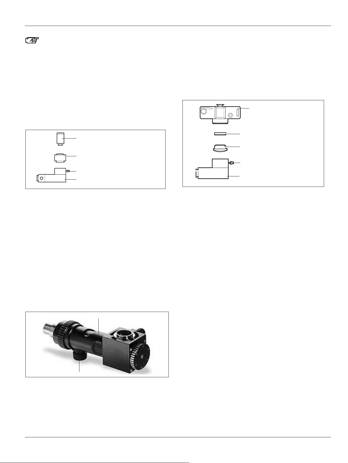
Fitting the photo/TV dual attachment
➩Install the dual attachment on the beam splitter.
➩Equip the video camera (1) with the TV objective (2) and insert
into the dual attachment.
➩Tighten the clamping screw.
➩Loosen the clamping screw and engage the video camera
until it engages in one of the 45° increments depending on
the available space.
➩Tighten the clamping screw.
➩Equip the photo camera (5) with camera adapter (4).
➩Screw the photo lens onto the camera adapter (4).
➩Fit the camera to the dual attachment.
➩Tighten the clamping screw.
1 Video camera
2 TV lens
3 Adapter M600 to M500 interface
4 Camera adapter
5 Photo camera and photo lens
The object image at the camera output is laterally
reversed!
1
2
54 3
Page 27
Preparation for operation
25
Leica M525 OH4 / Ref. 10 714 367 / Version -
Using the dial, the brightness of the video can be
adjusted to 30%, 50% or 100%. One of these filters can
be switched with the 8% filter provided. To do so,
remove the camera and change the filter in the TV
output.
TV attachment / zoom video adapter
➩Mount the TV attachment on the documentation port of the
beam splitter.
➩Screw the adapter to the camera using the C-mount.
➩Insert the camera with the adapter into the TV attachment
and tighten the clamping screw.
90° click-stop (TV attachment only):
➩Loosen the clamping screw.
➩Engage the camera at one of the 90° increments in
accordance with the space available and tighten the
clamping screw.
Setting the Zoom Video Adapter parfocal:
➩Set to the maximum magnification.
➩Place a flat test object with sharp contours under the
objective.
➩Look through the eyepieces and focus the microscope.
➩Set to the minimum magnification.
➩Set the maximum magnification (f=100) on the Zoom Video
Adapter.
➩Focus the monitor image on the Zoom Video Adapter.
➩Set the desired magnification on the Zoom Video Adapter.
Focusing knob
Adjusting the magnification
Video camera
C-mount adapter
TV attachment
Clamping screw
Fitting the phototube
➩Mount the phototube on the beam splitter.
➩Secure the camera adapter to the SLR camera.
➩Connect the f = 250mm or f = 350mm adapter to the camera
adapter.
➩Secure the camera, complete with adapter, in the phototube.
➩Tighten the clamping screw.
Camera adapter
Camera
Adapter
Phototube
Clamping screw
Page 28

Preparation for operation
26
Leica M525 OH4 / Ref. 10 714 367 / Version -
Selecting documentation accessories
Field of view
Monitor/image
1/4 “
1/3 “
1/2 “
2/3 “
Zoom video adapter Zoom video
TV
attachment
PhotoTV dual
attachment
TV
attachment
PhotoTV dual
attachment
Adapter
70mm
TV
attachment
107mm100mm85mm60mm55mm35mm
1“
35 mm
Digital
Photo
Camera
Photo/TV dual attachment
250 mm
350 mm
Page 29

Preparation for operation
27
Leica M525 OH4 / Ref. 10 714 367 / Version -
Stand settings
Automatic balancing of the Leica M525 OH4
Warning 5
Danger of injury due to movement of the microscope
during the balancing process.
➩Do not stand next to the microscope during the
balancing process.
Warning 6
Danger of injury due to the Leica M525 OH4 surgical
microscope moving down.
➩Never balance or re-equip the instrument over the
field of operation.
➩Balance the Leica M525 OH4 surgical microscope
after re-equipping it.
➩Do not release the brakes when the instrument is in an
unbalanced state.
➩Never perform intraoperative AC / BC balancing over
the patient.
➩Switch on the Leica M525 OH4.
➩Install the accessories in the permitted weight range
(see Technical data, screen 80).
➩Align the accessories in the working position.
➩Press the "All Brakes" button on the CAN handle and move
the optical carrier into the A-position.
The mark (1) musty be pointing to A.
1
➩Press the autobalancing push-button (3) on the control unit.
During the balancing procedure, the push-button (2) flashes
green and an acoustic signal sounds (can be deactivated in the
service menu).
The following dialog window opens on the touch panel monitor:
The balancing procedure can be canceled at any time
using "Interrupt Balancing".
2
Page 30

Preparation for operation
28
Leica M525 OH4 / Ref. 10 714 367 / Version -
The first balancing step is complete when the acoustic signal
no longer sounds and the push-button (2) is no longer flashing.
If automatic balancing cannot be successfully completed, the
following dialog window opens:
➩Acknowledge with the "Close" button.
➩Correct the alignment of the optical carrier (A-position).
➩Press push-button (2).
Autobalancing re-starts.
➩Press the "All Brakes" button on the CAN handle, tilt the
optical carrier forwards 90° and move it into the B-position.
The mark (1) must be pointing towards B.
If the mounted accessories (e. g. the assistant's tube)
do not allow a 90° tilt movement, turn the tube
upwards, tilt the optical carrier forwards and move the
tube back into its working position.
➩Press the autobalancing push-button (2) on the control unit
again.
During the balancing procedure, the push-button (2) flashes
yellow and an acoustic signal sounds (can be deactivated in
the service menu).
2
1
Page 31

Preparation for operation
29
Leica M525 OH4 / Ref. 10 714 367 / Version -
➩The following dialog window opens on the touch panel:
The balancing procedure can be canceled at any time
using "Interrupt Balancing".
➩Balancing is complete when the acoustic signal no longer
sounds and the push-button (2) is no longer flashing.
A dialog window indicates that balancing has been completed.
➩Press the "Close" button or wait until the dialog window is
closed automatically after 5 seconds.
➩Check the balancing.
➩Press the "All Brakes" button on the CAN handle and position
the microscope.
The microscope must remain fixed in any position.
If automatic balancing cannot be successfully completed, the
following dialog window opens:
➩Acknowledge with the "Close" button.
➩Correct the alignment of the optical carrier (B-position).
➩Press the push-button (2).
Autobalancing re-starts.
Page 32

Preparation for operation
30
Leica M525 OH4 / Ref. 10 714 367 / Version -
Intraoperative balancing
Warning 4
Danger of injury due to movement of the microscope
during the balancing process.
➩Do not stand next to the microscope during the
balancing process.
Warning 5
Danger of injury due to swinging down of the
Leica M525 OH4 surgical microscope.
➩Never balance or re-equip the instrument over the
field of operation.
➩Balance the Leica M525 OH4 surgical microscope
after re-equipping it.
➩Do not release the brakes when the instrument is in an
unbalanced state.
Intraoperative AC/BC balancing allows re-balancing during the
operation. Re-balancing may be necessary if, for instance, an
assistant's tube is adjusted.
Either axes A and C or B and C can be balanced.
For best results, it is recommended to balance axes A
and C before balancing axes B and C.
A/C balancing
If work is performed only in the horizontal microscope position,
re-balancing of the A/C axes may be sufficient.
➩Press the "All Brakes" button on the CAN handle and move
the optical carrier into the A-position.
The mark (2) must be pointing towards A.
1
➩Press the start button for automatic AC/BC balancing on the
swing arm.
During the balancing procedure, the push-button (2) on the control unit flashes green and an acoustic signal sounds.
The A-axis is balanced first, followed by the C-axis.
B/C balancing
If work is performed only in the upright microscope position, rebalancing of the B/C axes may be sufficient.
➩Press the "All Brakes" button on the CAN handle and move
the optical carrier into the B-position.
The mark (3) must be pointing towards B.
3
2
Page 33

Preparation for operation
31
Leica M525 OH4 / Ref. 10 714 367 / Version -
➩Press the start button (1) for automatic AC/BC balancing on
the swing arm.
During the balancing procedure, the push-button (2) on the control unit flashes yellow and an acoustic signal sounds.
The B-axis is balanced first, followed by the C-axis.
➩Check the balancing.
➩Press the "All Brakes" button on the CAN handle and position
the microscope.
The microscope must remain fixed in any position.
➩Correct the balancing, if necessary.
2
1
Correcting the balancing manually
For manual balancing, the axes can be moved manually using
switches (3), (4) and (5).
Make sure that no accessories collide with the
microscope during manual balancing.
3
5
4
Page 34

Preparation for operation
32
Leica M525 OH4 / Ref. 10 714 367 / Version -
➩Check the balancing.
➩Press the "All Brakes" button on the CAN handle.
The optical carrier tilts to the right:
➩Move the C-axis to the left with switch (1) until the optical
carrier is balanced.
The optical carrier tilts to the left:
➩Move the C-axis to the right with switch (1) until the optical
carrier is balanced.
The optical carrier (in the A-position) tilts back:
➩Move the A-axis forwards with switch (2) until the optical
carrier is balanced.
2
1
The optical carrier tilts forwards:
➩Move the A-axis back with switch (2) until the optical carrier
is balanced.
.
The optical carrier (in the B-position, e.g. for posterior fossa
operations) tilts back:
➩Move the B-axis forwards with switch (x) until the optical
carrier is balanced.
The optical carrier tilts forwards:
➩Move the B-axis back with switch (x) until the optical carrier
is balanced.
If the microscope cannot be balanced manually, the
weight of the accessories is probably outside the
balanceable weight range. This can only be done for A,
B and C axes by reducing or increasing the accessory
weight to within the permitted range (see page 80).
3
Page 35

Preparation for operation
33
Leica M525 OH4 / Ref. 10 714 367 / Version -
Correcting the D-balancing manually
The internal weight (3) in the stand balances the weight of the
surgical microscope and the installed accessories.
It may be necessary to correct the D-balancing after
fitting a sterile drape on the microscope.
D
D
1
The D-balancing of the stand can be corrected with the "+" and
"-" keys on the "Main" screen of the control unit.
"+" key: correction for higher load on the optical carrier
"-" key: correction for reduced load on the optical carrier
To balance the D-axis when using accessories with different weights, the number of D-axis weight disks can
be adapted accordingly (see below).
Page 36

Preparation for operation
34
Leica M525 OH4 / Ref. 10 714 367 / Version -
Changing the weight disk on the D-axis
If the Leica M525 OH4 cannot balance the accessories in use,
a weight disk must be added to or removed from the D-axis.
Caution 1
Danger of injury due to falling weight disk or cover!
➩When changing the weight disk, make sure that your
feet are not beneath the weight disk or the cover.
➩Locking the Leica M525 OH4 in position (see page 22).
➩Detach the cover (1) from the axis.
1
➩Unscrew the hexagon nut (3).
➩Add or remove the disk (2).
➩Screw on the hexagon nut (3).
➩Re-attach the cover (1).
No. of Load
weight disks D-axis
Heavy Light Min. Max.
2 1 6.65 10.22
2* 2 7.4 10.88
2 3 7.9 11.54
*Standard configuration
2
3
Page 37

Preparation for operation
35
Leica M525 OH4 / Ref. 10 714 367 / Version -
Releasing the brakes
The Leica M525 OH4 surgical microscope has six
electromagnetic brakes which stop the movements of the stand
and surgical microscope:
• Up/down and forward/back in parallelogram (0 and 1)
• Base (2)
• In swing arm (3)
• On the A and B carriages of surgical microscope (4)
• In the rotary joint (5)
The CAN handle key with the "Selected Brakes" function (see
also Assigning CAN handles, page 50) can release two different
brake combinations: "Focus Lock" or "XYZ Free".
The brake combination "Focus Lock" is set as the
default.
➩Activate the desired brake combination "Focus Lock" or
"XYZ Free" on the touch panel in the "Speed" menu by clicking
the relevant button.
The button for the selected brake combination lights up green.
You can save the desired brake combination
individually for each user in the user settings in the
"Start Values Speed" menu.
The following movements can be performed with the surgical
microscope when the brake combination "XYZ Free" is
activated:
The following movements can be performed with the surgical
microscope when the brake combination "Focus Lock" is
activated:
5
3
1
4
0
2
Page 38

Preparation for operation
36
Leica M525 OH4 / Ref. 10 714 367 / Version -
Transport, transporting and rest
positions
Warning 6
Danger of injury due to:
• Uncontrolled lateral movement of the swing arm!
• Tilting of the stand!
• Feet in lightweight shoes could become trapped
beneath the casing of the base.
➩For transportation, always move the Leica M525 OH4
surgical microscope into the transport position.
➩Never move the stand in the extended condition.
➩Never roll over cables lying on the floor.
➩Always push the Leica M525 OH4 surgical microscope
- never pull it.
Caution 2
Surgical microscope can move without warning!
➩Always lock the footbrake when you are not moving
the system.
Transport position
Always move your Leica M525 OH4 into the transport position
before transporting it.
Caution 3
Damage to the Leica M525 OH4 surgical microscope
due to uncontrolled tilting!
➩Hold the CAN handle when releasing the brake.
Caution 4
Damage to the Leica M525 surgical microscope during
transportation!
➩Never move the stand in the extended condition.
➩Never roll over cables lying on the floor.
➩Press the "All Brakes" button and move the Leica M525 OH4
into the transport position (see illustration below).
Make sure that the video monitor does not collide with
the horizontal arm and the vertical arm of the stand.
➩Unplug and secure the power cable.
➩Release the footbrake.
➩Depress the footbrake at the front end (FREE).
The footbrake disengages and is released.
➩Move the Leica M525 OH4 using the handle.
Rest position
Bring the microscope into rest position after use.
➩Push the microscope in the transport position to its storage
location.
➩Depress the footbrake at the rear end (LOCK) until it engages.
➩Pull the protective cover over the Leica M525 OH4.
Page 39

Preparation for operation/Use
37
Leica M525 OH4 / Ref. 10 714 367 / Version -
Positioning on the operating table
Warning 3
Risk of injury through surgical microscope moving down!
➩Never balance or re-equip the instrument over the
field of operation.
➩Always lock the Leica M525 OH4 in position before re-
equipping it.
➩Balance the Leica M525 OH4 after re-equipping it.
➩Do not release the brakes when the instrument is in an
unbalanced state.
The Leica M525 OH4 can be positioned easily on the operating
table and offers a variety of possibilities for operations on the
head or spinal column.
The M525 OH4 achieves this large range of positions through its
very long and high swing arm.
➩Release the footbrakes (see page 35).
➩Move the Leica M525 OH4 surgical microscope carefully over
to the operating table by the handle and into the required
position for the operation.
Positioning options:
➩Set footbrake.
➩Plug the footswitch into the stand and position it.
➩Plug the power cable into the stand.
➩Connect the equipotential bonding to the stand.
Attaching sterile controls
Sterilizable covers can be fitted on the rotary buttons on the
Leica M525 OH4 surgical microscope.
Covers for rotary buttons
Use the covers also when you use sterile disposable
drapes.
The controls will be more grippy.
➩Fit steam-sterilizable covers on the light field diameter adjust-
ment knob and the working distance adjustment knob.
➩Use steam-sterilizable covers also when using accessories.
Drape for footswitch
Packaging the footswitch in a plastic bag protects it
against dirt.
Page 40

Use
38
Leica M525 OH4 / Ref. 10 714 367 / Version -
Sterile drape for stand
You can also use an optional sterile disposable drape.
Caution 5
Risk of infection!
➩Leave sufficient space around the stand to ensure that
the sterile drape does not come into contact with nonsterile components.
➩Activate the "All Brakes" function on the CAN handle and
extend the swing arm.
➩Wear sterile gloves.
➩Attach all sterile controls.
➩Unpack the sterile drape carefully and drape it over the
Leica M525 surgical microscope as far as the swing arm.
➩Clamp the protective glass (optional) onto the objective.
➩Do not attach the sterile drape too tightly with the provided
ribbons. It must still be easy to move the instrument.
Check the ease of movement of the instrument.
Follow the instructions provided by the manufacturer of
the sterile drape.
Attaching the protective glass to the objective
➩Place the gas-sterilizable protective glass on the objective so
that the marks on the optical carrier (1) and protective
glass (2) are aligned one above the other.
➩Insert the protective glass upwards into the bayonet mount in
direction (a).
➩Turn the protective glass in direction (b) until it engages.
a
b
1
2
Positioning the microscope
Coarse positioning
➩Hold the microscope by both CAN handles.
➩Press the button for releasing the brakes and position the
microscope.
➩Release the brakes button.
Also refer to the "Release brakes" chapter on page 34.
Caution 3
Damage to the Leica M525 OH4 surgical microscope
due to uncontrolled tilting!
➩Hold the CAN handle when releasing the brake.
Fine positioning
➩Position the microscope with the XY drive using the joystick
on the CAN handle or the joystick on the footswitch.
In the "Speed" menu you can adjust the speed at which
the XY motors are operated.
This value can be saved individually for each user
(see page 46).
Page 41

Use
39
Leica M525 OH4 / Ref. 10 714 367 / Version -
Adjusting the microscope
Switching on the illumination
➩Press push-button (1) for illumination.
The illumination comes on and the push-button is lit green.
Leave the main and backup illumination on for at least
5 minutes, as otherwise luminosity will decrease
rapidly.
Adjusting the brightness
Brightness can be increased or decreased using the touch
panel monitor or a handswitch/footswitch or CAN handle.
On the touch panel monitor:
➩Press the "+"- or "-" key on the brightness adjustment bar for
illumination.
or
➩Adjust the brightness directly in the bar.
The brightness of the active main illumination changes.
Clicking the "+" or "-" key changes the brightness value
in increments of one. Holding down the mouse button
with your finger changes the value in increments of
five.
The start setting can be saved individually for each
user.
The main illumination can only be switched on and off
using the illumination push-button (on/off) (1).
The brightness setting is also visible when the illumination is off. However, the display bar will appear darker.
On the handswitch/footswitch /CAN handle:
Depending on assignment (see page 48), the brightness of the
main illumination can also be increased or decreased using two
correspondingly assigned keys on the handswitch/footswitch/
CAN handle.
BrightCare™
BrightCare™ is a safety function which automatically limits the
maximum brightness depending on the working distance.
Excessively bright light can, in combination with a short
working distance, cause burns in patients.
Explanation of luminous energy:
The optics of the Leica M525 OH4 surgical microscope have a
variable working distance of between 207 and 470mm. The system is designed in such a way that it delivers sufficient light to
produce a bright image even at a long working distance of
470mm.
According to the formula Ev=Iv/d2, luminous energy increases
constantly to 510% as a function of a reduction in working
distance from 470 to 207mm. (Ev = light intensity, Iv= brightness,
d= distance from light source).
This means that less light is required to work with the
microscope at a shorter distance than at a greater distance.
It is advisable to begin with a low light output and increase the
light intensity until an optimum level of illumination is achieved.
With "BrightCare™" the safety function is activated for
all users in the factory default configuration.
Explanation of heat release:
Heat from non-visible light (over 700nm) is filtered out of the
light from the used xenon light source. Nevertheless, white light
always releases heat. An excessive amount of white light can
cause overheating of tissue and metallic objects.
Therefore, it is advisable to begin with a low light intensity and
increase this until an optimum level of illumination is achieved.
1
Page 42

Use
40
Leica M525 OH4 / Ref. 10 714 367 / Version -
The red line on the brightness adjustment bar shows the
maximum adjustable brightness for the current working
distance.
The brightness cannot be set to a level beyond the red line
When the working distance is reduced by too little at a set
brightness, the brightness is reduced automatically.
This safety function can be deactivated by clicking the
"Brightcare™" button. A dialog window opens in which
you have to confirm that you want to deactivate the
safety function.
When the "Brightcare™" safety function is deactivated, the
color of the "Brightcare™" button changes from green to yellow.
Warning 7
At a short focal distance, the light source of the
illumination unit may possibly be too bright for the
operating physician and the patient.
➩Start with a low light level and gradually increase the
light intensity until the operating physician has an optimally illuminated image.
The status of the "BrightCare™" safety function can
only be changed permanently in the "User settings"
menu. A change in status during operational
procedures will not be stored when the user settings
are saved with "Save" or "Save as"!
Reactivating the "Brightcare™" safety function:
➩Click the yellow "BrightCare™" button again.
"BrightCare™" is now activated and the button is again lit green.
Page 43

Use
41
Leica M525 OH4 / Ref. 10 714 367 / Version -
Changing lamps
In case of failure of the xenon main illumination, your
Leica M525 OH4 automatically uses the second xenon lamp as
backup illumination.
You can also switch manually to the backup
illumination with the "Change Lamp" button on the
"Main" screen.
Replace the defective lamp at the next opportunity.
Never begin an operation with only one functioning
xenon lamp.
A dialog window informs you when the xenon lamp is
losing luminosity. We recommend that you keep a
replacement lamp handy.
Changing over to backup illumination
➩Undo screw knob (3) and open the access door (2) for lamp
inserts on the illumination unit.
The push-button (1) flashes orange.
Caution 6
Hot lamp insert can cause burns!
➩Do not touch the hot lamp insert.
➩Push down the lamp quick changer (4).
4
1
2
3
Page 44

Use
42
Leica M525 OH4 / Ref. 10 714 367 / Version -
Setting the illumination field diameter
Caution 7
Heating of tissue!
If the illumination field diameter is larger than the
visual field and the light intensity is set too high, uncontrolled heating of tissue can occur outside the visible
range of the microscope.
➩Do not set the light intensity too high.
The light field diameter is automatically adapted to the size of
the visual field at the Leica M525 optical carrier. The
illumination field diameter can also be adjusted manually with
rotary button (2). Automatic adjustment can be deactivated with
the rotary button and reactivated with the Reset button (1).
If the illumination field diameter is blocked at a high
light intensity in a high zoom setting, and cannot be
adjusted automatically or manually, then the light
intensity must be reduced in order to protect the tissue.
If the illumination field diameter remains blocked in a
low zoom setting, and cannot be adjusted
automatically or manually, then an OP lamp can be
used for better illumination of a large visual field (low
zoom setting).
Adjusting the magnification (zoom)
You can set the magnification with a footswitch/handswitch or
with the "Magnification" adjustment bar in the "Main" menu of
the control unit.
Clicking the "+" or "-" key changes the magnification
value in increments of one. Holding down the mouse
button with your finger changes the value in
increments of five.
You can adjust the zoom motor speed in the "Speed"
menu.
These values can be saved individually for each user
(see page 46).
Warning 8
Danger to the patient due to failure of the zoom motor!
➩In case of failure of the zoom motor, the zoom can be
adjusted manually.
Manually adjusting the magnification (zoom)
Caution 8
Destruction of the zoom motor!
➩Use the manual adjustment of the zoom motor only if
the zoom motor is defective.
In case of failure of the zoom motor, the zoom can be adjusted
manually using rotary button (3).
➩Hold down rotary button (3).
➩Set the desired magnification by turning the knob.
3
2
1
Page 45

Use
43
Leica M525 OH4 / Ref. 10 714 367 / Version -
Setting the focus manually
Warning 11
Danger of serious damage to tissue due to incorrect
manual adjustment of the working distance!
➩Do not adjust the rotary button for manual setting of
the working distance while using the laser.
In case of failure of the focus motor, the focus can be adjusted
manually using rotary button (2).
➩Turn rotary button (2) and set the focus as required.
Locking/releasing the focus
It is necessary to lock the focus when working at a
fixed distance or when using the laser.
➩Press key (3).
The yellow LED (4) comes on and the focus is locked.
➩Press key (3) again.
The yellow LED (4) goes out and the focus is released.
Setting the working distance (focus)
Warning 9
Danger of serious damage to tissue due to incorrect
working distance!
➩When using lasers, always set the working distance of
the microscope to laser distance and lock the
microscope in position.
You can set the working distance with the footswitch/handswitch or with the "WD" adjustment bar in the "Main" menu of
the control unit.
Clicking the "+" or "-" key changes the working distance
in increments of one. Holding down the mouse button
with your finger changes the value in increments of
five.
You can adjust the focus motor speed in the "Speed"
menu.
Using the Reset WD button, the focus motor can be set
to the working distance which has been saved for the
current user (see page 46).
You can save the currently set working distance on the
"Main" screen of the control unit or read it off the
display (1) on the M525 optical carrier.
Warning 10
Danger to patient due to failure of the zoom motor!
➩In case of failure of the zoom motor, the zoom can be
adjusted manually.
2
34
1
Page 46

Use
44
Leica M525 OH4 / Ref. 10 714 367 / Version -
Switching the microscope on
➩Switch on the microscope at the power switch (2) on the
stand.
After the surgical microscope is switched on, the settings of the
last active user are loaded.
➩Switch on the illumination with the key (1) on the control unit.
In operational mode, the status bar displays the current
user and specifies the current location in the menu at
all times.
Control unit with touch panel
Menu structure
1 Quick access to the screens "Main", "Speed", "Menu",
"DI C500" and "Help"
2 Warning messages
3 Status line
4 Display range
5 Dynamic button bar
1
2
3
4
5
1
2
Page 47

Use
45
Leica M525 OH4 / Ref. 10 714 367 / Version -
Selecting users
In the "Main" and "Speed" menus, three buttons are always dis-
played in the dynamic button line: "Presets", "User List" and
"Show Settings".
You can find a list of default users preset by Leica for the most
common types of operation under "Presets".
➩Select one of the preset default users and click "Load".
The Leica M525 OH4 surgical microscope is ready to operate
straight away.
You can adapt and save the settings of these default
users as required (see page 44).
You can click the "Show Settings" button at any time to
see an overview of the user settings of the current
user.
Clicking the "User List" button opens a two-screen list of users
from which you can select one of up to 30 configurable users.
Click the "1-15" or "16-30" button to switch between screens.
➩Select user and click "Select".
The user settings are loaded.
When the user list is open, it can be edited at any time
(see page 45).
Before every operation, make sure the required user is
selected and familiarize yourself with the assignments
of the CAN handle and, if used, the optional footswitch.
➩Click “Show Settings” button to see an overview of the user
settings of the curent user.
Page 48

Editing the user list
Various functions are available in the user list depending on the
situation.
➩Select user.
The available functions are displayed in the dynamic button
line:
• "Move"
Moves the selected user to another available location of your
choosing.
• "Delete"
Deletes the selected user.
Finally, you must confirm this action with "Acknowledge".
• "Rename"
Renames an existing user. The user's settings are not
changed.
In the "User Settings" menu, click the "Edit User List"
button to access the dynamic button line in user list
edit mode.
We recommend that you do not change the configuration of the user settings or edit the user list during an
operation.
Use
46
Leica M525 OH4 / Ref. 10 714 367 / Version -
Configuring users (User Settings menu)
You can configure user settings in this menu.
• "Load"
Loads the settings of an existing user from the user list for
modifying.
• "New User"
Opens a new user with "blank" settings.
• "New (Preset)"
Opens the "Preset" screen for selecting a default user in order
to create a new user with the settings of the desired preset
and to load or modify the user's settings.
You can also add a user from the operational menu. If
you want to keep the current settings, you can save
them by clicking the "Save" button (which appears as
soon as the basic settings of the current users have
been changed), either for the current user ("Save") or
under a new username ("Save as").
Page 49

Use
47
Leica M525 OH4 / Ref. 10 714 367 / Version -
Saving user settings
➩Click the "Save" button.
➩In the user list select an available location where the user
can be saved.
If you like, you can edit the user list first.
➩Enter the desired username using the keyboard.
➩Click the "Save" button to save the user at the desired
location under the name you have entered.
Setting the "Main" start values
On this screen, you can set the start values for illumination,
working distance and magnification.
Clicking the "+" or "-" key changes the values in
increments of one. Holding down the mouse button
with your finger changes the value in increments of
five.
You can also set the desired value by directly clicking
the bars.
On the "Main" user settings screen you can set the status of the BrightCare™ safety function for the selected
user.
On the "Main" user settings screen you can
permanently save the default settings for WD-Reset. If
"WD Reset" is activated, the focus motor automatically
moves to the working distance saved for each user in
the user settings when "All Brakes" are released. This
function is deactivated in the factory default configuration.
➩Click the "WD-Reset" button.
The "WD-Reset" function is activated, the "WD-Reset" button
changes color form gray to green.
Page 50

Use
48
Leica M525 OH4 / Ref. 10 714 367 / Version -
Setting the drive start values
You can set the start values for the travel speed of the zoom,
focus and XY motors on this screen.
Clicking the "+" or "-" key changes the values in
increments of one. Holding down the mouse button
with your finger changes the value in increments of
five.
You can also set the desired value by directly clicking
the bars.
On the "Speed" menu screen you can also select the
desired brake combination "Focus Lock" or "XYZ Free"
for the CAN handle function "Selected Brakes".
➩Activate the desired brake combination "Focus Lock" or
"XYZ Free" on the touch panel in the "Speed" menu by clicking
the relevant button.
The button for the preselected brake combination lights up
green.
Footswitch/handswitch assignment
Here, you can configure individual settings for each user for the
footswitch/handswitch you are optionally using.
➩Select the footswitch/handswitch you are using in the right
options menu.
You can scroll forwards or backwards in the list by
clicking the arrowheads.
You can also connect the 6-function footswitch to the
Leica M525 OH4 as an option. The existing 6 switches
have the same functions as the currently selected 12 or
16-function footswitch.
➩Click the "Default" button.
The default settings are assigned to the selected
footswitch/handswitch.
You can then modify these settings as you like.
Clicking the "Clear All" button clears the assignments
for all keys.
Page 51

Use
49
Leica M525 OH4 / Ref. 10 714 367 / Version -
Configuring individual keys
➩Select the footswitch/handswitch you are using in the right
options menu.
You can scroll forwards or backwards in the list by
clicking the arrowheads.
➩Select the function group with the desired functions in the left
options menu.
You can scroll forwards or backwards in the list by
clicking the arrowheads.
➩Select the desired function.
➩Click the caption of the desired key to assign the selected
function to it.
or
➩Press the corresponding key on the connected footswitch.
Overview of function groups
Drive: Magnification +
Magnification Focus +
Focus No function
Extra: AD.F.1 Toggle
AD.F.1 Pulse
AD.F.2 Toggle
AD.F.2 Pulse
MDRS 3 Record Start/Stop
XGA Out toggle 1/2
XGA Out toggle 1/2/3
Video toggle source
AF500 Start
No function
You can change the status of a function with the
"Toggle" function (e.g. on/off). The "Pulse" function continuously changes a status (such as increasing the
brightness).
Light: Illumination +
Illumination No function
XY: X+
XY+
YXY Complete
No function
With the "XY Complete" function, you can assign all four
functions of the joystick simultaneously.
Fluorescence: FL400 Mode On/Off
FL800 Mode On/Off
FL800 NIR Zoom Reset
MDRS3 FL:Record Start/Stop
MDRS3 FL:Playback&Enter
MDRS3 FL:Menu&Down
No function
DI C500 / IGS: DI C500: Image Injection On/Off
DI C500: Shutter Control
DI C500: Brightness+
DI C500: BrightnessIGS 1
IGS 2
IGS 3
IGS 4
No function
To delete an assignment which you do not want, select
the "No function" element - which can be found in all
function groups - and assign it to the key in question.
If you are creating only one footswitch/handswitch
configuration for one user, we recommend duplicating
it to the second footswitch/handswitch input by pressing the "Duplicate" button.
This ensures that your footswitch/handswitch
functions the way you want it to, regardless of which
input it is plugged into.
Page 52

Use
50
Leica M525 OH4 / Ref. 10 714 367 / Version -
CAN handle assignments
On the two CAN handle assignment screens, you can assign up
to nine functions of your choice to the left and right CAN
handles.
The "All Brakes" function is always assigned to the rear
switch (1) for both CAN handles, and can neither be
overwritten nor deleted.
➩Select the function group with the desired functions in the left
options menu.
You can scroll forwards or backwards in the list by
clicking the arrowheads.
➩Select the desired function.
➩Click an available caption of the desired key to assign the
selected function to it.
The inner switch (2) to which "Selected Brakes" is preassigned can be freely assigned, as required.
You can also assign one of the four defaults "DI C500",
"X/Y", "FL400", "FL800" completely to each CAN handle.
1
2
Page 53

Use
51
Leica M525 OH4 / Ref. 10 714 367 / Version -
Tube Settings
On this screen, you can store the diopter values and interpupillary distance for each user.
You can set the user-specific values by clicking the
arrowheads. These values are shown for the current
user in the status line.
Page 54

Use
52
Leica M525 OH4 / Ref. 10 714 367 / Version -
Leica DI C500
Operating the control unit
If you are using a DI C500, a Quick Access Button "DI C500" is
added to the static menu line.
Changing the current brightness of the image data:
➩Press the "+" or "-" key on the "DI C500" screen.
or
➩Adjust directly by clicking the brightness adjustment bar.
Clicking the "+" or "-" key changes the brightness value
in increments of one. Holding down the mouse button
with your finger changes the value in increments of
five.
Press button “Image off” to switch of the DI C500
display (brightness = 0 %).
You can also adjust the brightness of the image data
using the CAN handle/footswitch.
Controls on the CAN handle/footswitch
You can assign the following functions to your CAN handle/
footswitch for controlling your Leica DI C500 (see page 12):
"DI C500: Image Injection on/off"
Switches the data display on/off manually. The shutters are
switched as pre-configured in the user settings.
You require this function for example when you want to
display endoscope data on your Leica DI C500.
"DI C500: Shutter Control"
Opens or closes the shutter manually as pre-configured in the
user settings.
"DI C500: Brightness+"
Increases the brightness of the image data.
"DI C500: Brightness-"
Reduces the brightness of the image data.
User settings
You can configure the following settings for the user in the user
settings:
• Default brightness for the injection of overlay data and non
overlay data
• Shutter settings for manual operation
• Shutter settings
• Surgeon's shutter settings
Setting the default brightness for the injection of overlay data
and non overlay data:
➩To adjust the brightness, press the "+" or "-" key or click
directly in the bar.
Page 55

Use
53
Leica M525 OH4 / Ref. 10 714 367 / Version -
Clicking the "+" or "-" key changes the brightness value
in increments of one. Holding down the mouse button
with your finger changes the value in increments of
five.
Shutter settings for manual operation:
You can adapt these settings intraoperatively using the
CAN handle or on the "DI C500" screen on the control
unit (see page 48).
Shutter settings:
➩Specify how data are to be displayed on your Leica DI C500 in
the options menu "Manual Shutter Settings (Main Shutter)".
Overlay Data (open)
Displayed data are overlaid on the object.
All shutters are opened.
Non-Overlay (closed)
Displayed data are displayed on a black background. The shutter on the display side is closed.
A connected IGS navigation system automatically controls the shutter independent of this setting.
Surgeon's shutter settings
➩In the options menu "Surgeon Shutter Settings (Non Overlay
Data)" specify whether you want with or without object view
in the non reflected beam path on the surgeon's side.
Surgeon's shutter closed
The second beam path is dimmed. In the other beam path, the
data is displayed on a dark background.
This setting does not affect the assistant's view.
Surgeon's shutter open
You have a view of the object in the second beam path. In the
other beam path, the data is displayed on a dark background.
In the preview window you can view the shutter
settings you have selected, depending on the display
side that is currently set on your Leica DI C500.
Page 56

Use
54
Leica M525 OH4 / Ref. 10 714 367 / Version -
Leica AF500
The autofocus Leica AF500 works with the cameras
Leica2, Sony DXC 33P and Leica UV-camera Hitachi.
Contact your Leica representative if you want to adapt
another camera.
We recommend to use the Leica AF500 only in
combination with a video adapter having a fix focal
length.
Operating
➩To switch on the autofocus press on/off button on the front
side of the housing.
➩Start autofocus function by pressing the corresponding
button on the CAN handle.
(see ”Footswitch/handswitch assignment “on page 48)
If you activate the „Brake starts Autofocus“ function in
the user settings menu the autofocus is automatically
focussing when releasing „All brakes“ or „Selected
Brakes“ .
If you activate the parfocality function in the user
settings menu the autofocus is always driving in maximum position first, then in minimum position and back
to current set working distance when focussing.
User settings in the control unit
The autofocus can be individually assigned for each
user in the "User Settings" menu.
Resize autofocus window
The preview shows actual size of the autofocus window. Autofocus window displays the area of the object that is to be
focussed on.
You can proportionately increase or decrease the size
of the autofocus window for your needs. The default
setting is 25%.
Clicking the "+" or "-" key changes the value in
increments of one. Holding down the mouse button
with your finger changes the value in increments of
five.
Because autofocus needs a flat image plane to be set
in focus you should reduce the size of the autofocus
window. The default Setting is 25%.
Adjusting the position of autofocus window
The preview shows actual position of the autofocus window.
Autofocus window displays the area of the object that is to be
focussed on.
You can move the position of the autofocus window.
Adjust value for X- and Y-position.
Clicking the "+" or "-" key changes the value in
increments of one. Holding down the mouse button
with your finger changes the value in increments of
five.
The default setting is 50 % along each axis. This places
the autofocus window exactly in the centre.
Page 57

Use
55
Leica M525 OH4 / Ref. 10 714 367 / Version -
The Maintenance menu
Hour meter for the bulbs (Lamp History)
On this screen, you can view the operating hours of xenon
lamp 1 and xenon lamp 2.
Whenever you replace a bulb, reset the bulb's hour
meter to 0 by double-clicking the "Reset" button.
Check switches
On this screen, you can test the footswitches/handswitches
and CAN handles you are using.
➩Select the connection you are using in the right upper options
menu.
➩You can scroll forwards or backwards in the list by clicking
the arrowheads.
➩Select the footswitch/handswitch or CAN handle to be tested
in the right lower options menu.
➩You can scroll forwards or backwards in the list by clicking
the arrowheads.
➩Press all of the keys, one after the other, of the
footswitch/handswitch or CAN handle you want to test.
If the key you have pressed is functioning properly, a green dot
appears on it on the display. The comment "Tested" appears in
the caption field of the key.
Page 58
Use
56 Leica M525 OH4 / Ref. 10 714 367 / Version -
Microscope settings
On this screen you can configure the accessories you are
using.
This ensures that the correct magnification is displayed on the
"Main" menu screen.
➩In the top options field, enter the tube currently being used by
the surgeon.
➩You can scroll forwards or backwards in the list by clicking
the arrowheads.
➩In the middle options field, select the magnification of the
eyepieces being used by the surgeon.
➩You can scroll forwards or backwards in the list by clicking
the arrowheads.
If you do not make a selection, the magnification is calculated for the standard equipment - binocular tube
30°-150° and eyepiece with 10x magnification.
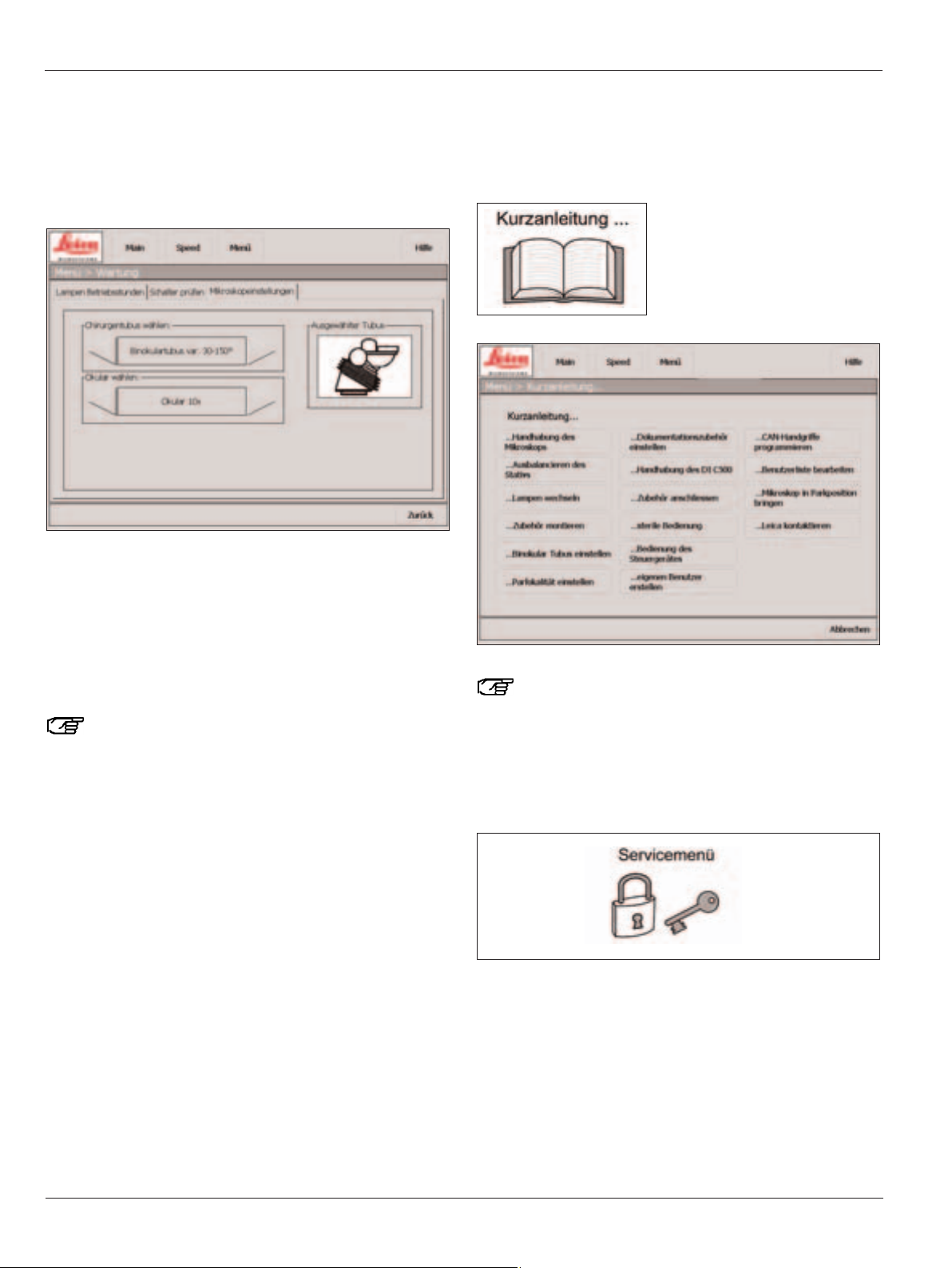
The "How to..." menu
This screen displays, in short form, user instructions for operating your surgical microscope.
The "Help" button in the static menu bar provides
access to the "How To..." screens at all times.
The Service menu
This area is password-protected.
Page 59

Use
57
Leica M525 OH4 / Ref. 10 714 367 / Version -
The Leica M525 OH4 surgical microscope is state-of-the-art
technology. Nevertheless, hazards can arise during operation.
➩Always follow the instructions in this user manual, and in par-
ticular the safety guidelines.
Intended use
• The Leica M525 OH4 surgical microscope is an optical instrument for improving the visibility of objects through magnification and illumination. It can be applied for observation and
documentation and for human and veterinary medical
treatment.
• The Leica M525 OH4 surgical microscope may be used only in
closed rooms and must be placed on a solid floor.
• The Leica M525 OH4 surgical microscope is subject to
special precautionary measures for electromagnetic compatibility. They must be installed and put into operation in accordance with the guidelines, manufacturer's declarations and
recommended safety distances (Tables 201, 202, 204, and 206
according to EN 60601-1-2:2001).
• Portable and mobile as well as stationary RF communications
equipment can have a negative effect on the reliability of the
Leica M525 OH4 surgical microscope.
Warning 12
Not suitable for use in ophthalmology!
Directions for the person responsible for
the instrument
➩Ensure that the Leica M525 OH4 surgical microscope is used
only by persons qualified to do so.
➩Ensure that this user manual is always available at the place
where the Leica M525 OH4 surgical microscope is in use.
➩Carry out regular inspections to make certain that the
authorized users are adhering to safety requirements.
➩When instructing new users, do so thoroughly and explain
the meanings of the warning signs and messages.
➩Assign individual responsibilities for starting, operating and
servicing the Leica surgical microscope and monitor the
observance of these responsibilities.
➩Only use the Leica M525 OH4 surgical microscope if it is free
of defects.
➩Inform your Leica representative or Leica Microsystems
(Schweiz) AG, BU SOM, 9435 Heerbrugg, Switzerland,
immediately if you detect a product defect that could
potentially cause injury or harm.
➩If you use accessories made by third-party manufacturers
with the Leica M525 OH4 surgical microscope, be sure that
each such manufacturer confirms the safety-engineering,
harmless usability of the product and observe the product's
user manual.
➩Modifications to or service on the Leica M525 OH4 surgical
microscope may be carried out only by technicians who are
explicitly authorized by Leica to do so.
➩Only original Leica replacement parts may be used in servic-
ing the product.
➩After servicing or making technical modifications, the instru-
ment must be re-set in accordance with our technical specifications.
➩Leica accepts no liability if the instrument is modified or
serviced by unauthorized persons, not maintained as
specified (unless maintenance is performed by us) or not
used/handled properly.
➩Interaction of other devices through the Leica surgical micro-
scope was proven in accordance with EN 60 601-1-2. The
system passed the emission and immunity test. The standard
safety precautions and safety requirements relating to
electromagnetic and other radiation must be observed.
➩Domestic electrical installation must be conducted in
accordance with the national standard, e.g. use of a residual
current protective device (FI protection) is recommended.
➩As with every other instrument used in operative
applications, this system is subject to failure. Leica
Microsystem (Schweiz) AG therefore recommends that a
backup system be kept available during the operation.
Page 60

Safety notes
58
Leica M525 OH4 / Ref. 10 714 367 / Version -
Directions for the operator of the
instrument
➩Follow the instructions described here.
➩Follow the directions provided by your employer regarding
work organization and safety.
Stability
When moved in the OP, the swing arm must be folded up and
locked and the brakes must be applied, otherwise the swing
arm may drift out of control and the stand could topple.
Hazards due to moveable parts
This section describes uses that, inadvertently, could lead to
hazardous situations.
• Add accessories and balance the stand before the operation,
and never over the field of operation.
• Do not put your fingers between the microscope and the
focusing drive; they could get crushed.
Floor stand:
• When displacing the stand, push it. Do not pull it. Feet in lightweight shoes could become trapped beneath the casing of
the base.
• The footbrakes must remain engaged throughout the
operation.
Electrical terminals
The control unit may be opened only by a Leica-approved
service technician.
Accessories
Only the following accessories may be used on the
Leica M525 OH4 surgical microscope:
• The Leica accessories described in this user manual.
• Other accessories, provided that these have been expressly
approved by Leica as being technically safe in this context.
Page 61

Safety notes
59
Leica M525 OH4 / Ref. 10 714 367 / Version -
Dangers of use
Warning 1
Danger of fatal electrical shock!
➩The Leica M525 OH4 surgical microscope may be con-
nected to a grounded safety socket only.
Warning 2
Danger of fatal electric shock.
➩Operate the system only with all equipment in its
proper position (all covers fitted, doors closed).
Warning 3
Risk of injury through surgical microscope moving
down!
➩Complete all preparations and adjustments to the
stand before the operation.
➩Never balance or re-equip the instrument over the
field of operation.
➩Always lock the Leica M525 OH4 in position before re-
equipping it.
➩Balance the Leica M525 OH4 after re-equipping it.
➩Do not release the brakes when the instrument is in an
unbalanced state.
➩Before re-equipping during the operation, first swing
the microscope away from the operating field.
Warning 4
Danger of injury due to movement of the microscope
during the balancing process.
➩Do not stand next to the microscope during the
balancing process.
Warning 5
Danger of injury due to swinging down of the
Leica M525 OH4 surgical microscope.
➩Never balance or re-equip the instrument over
the field of operation.
➩Balance the Leica M525 OH4 surgical microscope
after re-equipping it.
➩Do not release the brakes when the instrument is
in an unbalanced state.
➩Never perform intraoperative AC / BC balancing
over the patient.
Warning 6
Danger of injury due to:
• Uncontrolled lateral movement of the swing arm!
• Tilting of the stand!
• Feet in lightweight shoes could become trapped
beneath the casing of the base.
➩For transportation, always move the Leica M525 OH4
surgical microscope into the transport position.
➩Never move the stand in the extended condition.
➩Never roll over cables lying on the floor.
➩Always push the Leica M525 OH4 surgical microscope
- never pull it.
Warning 7
At a short focal distance, the light source of the
illumination unit may possibly be too bright for the
operating physician and the patient.
➩Start with a low light level and gradually increase the
light intensity until the operating physician has an optimally illuminated image.
Warning 8
Danger to the patient due to failure of the focus motor!
➩In case of failure of the focus motor, the focus can be
adjusted manually.
Warning 9
Danger of serious damage to tissue due to incorrect
working distance!
➩When using lasers, always set the working distance of
the microscope to laser distance and lock the
microscope in position.
Warning 10
Danger to patient due to failure of the zoom motor!
➩In case of failure of the zoom motor, the zoom can be
adjusted manually.
Warning 11
Danger of serious damage to tissue due to incorrect
manual adjustment of the working distance!
➩Do not adjust the rotary button for manual setting of
the working distance while using the laser.
Warning 12
Not suitable for use in ophthalmology!
Page 62

Safety notes
60
Leica M525 OH4 / Ref. 10 714 367 / Version -
Caution 1
Danger of injury due to falling weight disk or cover!
➩When changing the weight disk, make sure that your
feet are not beneath the weight disk or the cover.
Caution 2
Surgical microscope can move without warning!
➩Always lock the footbrake when you are not moving
the system.
Caution 3
Damage to the Leica M525 OH4 surgical microscope
due to uncontrolled tilting!
➩ Hold the CAN handles securely before you press the
"All Brakes" button.
Caution 4
Damage to the Leica M525 surgical microscope during
transportation!
➩Never move the stand in the extended condition.
➩Never roll over cables lying on the floor.
Caution 5
Risk of infection!
➩Leave sufficient space around the stand to ensure that
the sterile drape does not come into contact with nonsterile components.
Caution 6
Hot lamp insert can cause burns!
➩Do not touch the hot lamp insert.
Caution 7
Heating of tissue
If the illumination field diameter is larger than the
visual field and the light intensity is set too high, uncontrolled heating of tissue can occur outside the visible
range of the microscope.
➩Do not set the light intensity too high.
Caution 8
Destruction of the zoom motor!
➩Use the manual adjustment of the zoom motor only if
the zoom motor is defective.
Caution 9
Damage of the touch panel
➩Operate the touch panel using your fingers only.
Never use hard, sharp or pointed objects made out of
wood, metal or plastic.
Caution 10
Damage of the touch panel
➩Never clean the touch panel using cleaners that
contain abrasive substances. These substances can
scratch the surface and cause it to be become dull.
Caution 11
Danger of skin burns!
The lamp insert is very hot.
➩Before changing the lamp, make sure that the lamp
insert has cooled down.
Page 63

Safety notes
61
Leica M525 OH4 / Ref. 10 714 367 / Version -
Manufacturer's declaration of electromagnetic compatibility (EMC)
This "Guidance and manufacturer's declaration" document is based on EN 60601-1-2:2001.
Table 201 from EN 60601-1-2:2001
Guidance and manufacturer's declaration – electromagnetic emissions
The Leica M525 OH4 surgical microscope is intended for operation in an environment as specified below.
The customer or the user of the Leica M525 OH4 surgical microscope should make sure that it is used in such an environment..
Emissions test Compliance Electromagnetic environment – guidance
RF emissions Group 1 The Leica M525 OH4 surgical microscope uses RF energy only for its
according to CISPR 11 internal function. Therefore, its RF emissions are very low and are not
likely to cause any interference in nearby electronic equipment.
RF emissions Class A The Leica Leica M525 OH4 is suitable for use in establishments
according to CISPR 11 other than domestic and those directly connected to the public low-
voltage power supply network that supplies buildings used for residential
purposes.
Harmonic emissions Class A
according to
IEC 61000-3-2
Emissions of voltage compliant
fluctuations/flicker
according to IEC 61000-3-3
Page 64

Safety notes
62
Leica M525 OH4 / Ref. 10 714 367 / Version -
Safety notes
Table 202 from EN 60601-1-2:2001
Guidance and manufacturer's declaration – electromagnetic immunity
The Leica M525 OH4 surgical microscope is intended for operation in an environment as specified below.
The customer or the user of the Leica M525 OH4 surgical microscope should make sure that it is used in
such an environment.
Immunity test IEC 60601 test level Compliance level Electromagnetic environment – guidance
Discharge of static ± 6KV ± 6KV
electricity (ESD) according to
contact discharge contact discharge
IEC 61000-4-2
± 8KV air ± 8KV air
High-freq. transient ± 2KV for ± 2KV for
electrical interference / power lines power lines
Burst
according to IEC 61000-4-4 ± 1KV for input and ± 1KV for input and
output lines output lines
Surges ± 1KV ± 1KV
according to normal mode normal mode
IEC 61000-4-5
± 2KV ± 2KV
common mode common mode
Voltage drops <5% UT (>95% <5% UT (>95%
short interruptions dip in UT) dip in UT)
and voltage variations for 11/
22
cycle for 11/
22
cycle
IEC 61000-4-11
40% UT (60% 40% UT (60%
dip in UT) dip in UT)
for 5 cycles for 5 cycles
70% UT (30% 70% UT (30%
dip in UT) dip in UT)
for 25 cycles for 25 cycles
<5% UT (>95% <5% UT (>95%
dip in UT) dip in UT)
for 5 sec. for 5 sec.
Magnetic fields at 3 A/m not applicable
mains frequency
(50/60Hz) according to
IEC 61000-4-8
Note: UT is the a.c. mains voltage prior to application of the test level.
Floors should be of wood, concrete or
ceramic tile. If the floor is of synthetic material, the relative humidity must be at least
30%.
Mains power quality should be that of a
typical commercial or hospital environment.
Mains power quality should be that of a
typical commercial or hospital environment.
Mains power quality should be that of a
typical commercial or hospital environment.
If the user of the Leica M525 OH4 surgical
microscope requires that the instrument
remain functional even after mains power
interruptions, it is recommended that the
Leica M525 OH4 surgical microscope be
provided with an auxiliary power source
such as an uninterruptible power supply
(UPS) or battery back-up.
Page 65

63Leica M525 OH4 / Ref. 10 714 367 / Version -
Table 204 from EN 60601-1-2:2001
Guidance and manufacturer's declaration – electromagnetic immunity
The Leica M525 OH4 surgical microscope is intended for operation in an environment as specified below.
The customer or the user of the Leica M525 OH4 surgical microscope should make sure that it is used in
such an environment.
Immunity test IEC 60601 test level Compliance level Electromagnetic environment – guidance
Portable and mobile RF communications
should be used no closer to any part of the
Leica M525 OH4, including its cables, than
the recommended separation distance
calculated from the equation applicable to
the frequency of the transmitter.
Recommended separation distance:
Conducted RF – 3Veff 3Veff d = 2.4 P
Interference 150kHz to 80MHz for 150kHz to 80MHz
according to IEC 61000-4-6
Radiated RF – 3V/m 3V/m d= 2.4 P
Interference 80MHz to 2.5GHz for 80MHz to 2.5GHz
according to IEC 61000-4-6
where Pis the maximum output power rating
of the transmitter in watts (W) according to
the transmitter manufacturer and d is the recommended separation distance in meters (m).
Field strengths from fixed RF transmitters, as
determined by an electromagnetic site
survey, should be less than the compliance
level in each frequency range. Interference
may occur in the vicinity of equipment
marked with the following symbol:
Note 1: At 80MHz, the higher frequency range applies.
Note 2: These guidelines may not apply in all situations. Electromagnetic propagation
is affected by absorption and reflection from structures, objects and people.
a Field strengths from fixed transmitters, such as base stations for radio (cellular/cordless) telephones and land mobile radios,
amateur radio, AM and FM broadcast and TV broadcast cannot be predicted theoretically with accuracy. To assess the
electromagnetic environment due to fixed RF transmitters, an electromagnetic site survey should be considered. If the
measured field strength in the location in which the Leica M525 OH4 surgical microscope is used exceeds the applicable RF
compliance level above, the Leica M525 OH4 surgical microscope should be observed to verify normal operation. If abnormal
performance is observed, additional measures may be necessary, such as reorienting or relocating the Leica M525 OH4
surgical microscope.
b Over the frequency range 150kHz to 80MHz, field strengths should be less than 3V/m.
Page 66

Safety notes
64
Leica M525 OH4 / Ref. 10 714 367 / Version -
Table 206 from EN 60601-1-2:2001
Recommend separation distances between portable and mobile RF telecommunications equipment and
the Leica M525 OH4 surgical microscope
The Leica M525 OH4 surgical microscope is intended for operation in an electromagnetic environment in which RF interference is
controlled. The customer or the user of the Leica M525 OH4 surgical microscope can help prevent electromagnetic interference
by maintaining a minimum distance between portable and mobile RF communications equipment (transmitters) and the Leica
M525 OH4 surgical microscope as recommended below, according to the maximum output power of the communications
equipment.
Separation distance according to frequency of transmitter in m
Rated maximum output 150kHz to 2.5GHz
power of transmitter W
d = 2.4 P in m
0.01 0.24
0.1 0.8
1 2.4
10 8.0
100 24.0
For transmitters rated at a maximum output power not listed above, the recommended separation distance d in meters (m)
can be estimated using the equation applicable to the frequency of the transmitter, where P is the maximum output power
rating of the transmitter in watts (W) according to the transmitter manufacturer.
Note 1: These guidelines may not apply in all situations. Electromagnetic propagation is affected by
absorption and reflection from structures, objects and people.
Warning message:
If use is made of accessories or cables other than those specified in this user manual or approved by the manufacturer of the
Leica M525 OH4 surgical microscope, this can lead to an increase in electromagnetic radiation or a reduction in EMC.
Warning message:
The Leica M525 OH4 surgical microscope must not be used directly adjacent other instruments.
If it is necessary to operate them in the vicinity of other instruments, the microscopes should be monitored to ensure that they function properly in this arrangement.
Page 67

Safety notes
65
Leica M525 OH4 / Ref. 10 714 367 / Version -
Signs and labels
MITAKA KOHKI CO. LTD
No.
Made in Japan
DO NOT USE
IN OPHTALMOLOGY
1
2
5
8
4
Leica Microsystems (Schweiz) AG
CH-9435 Heerbrugg
LEICA M525 OH4
1600 VA 50/60 Hz
100/120/220/240 V
MODEL
PRIM 100/120 V PRIM 2xT10A
220/240 V PRIM 2xT8A
~
Grounding reliability
can only be achieved
when EQUIPMENT is
connected to
equivalent receptacle marked “Hospital only” or “Hospital Grade”.
La fiabilité de la mise à
la terre n’est assurée
que si l’équipement est
connecté à une prise
équivalente, marquée «Hôpital seulement» ou «Qualité hôpital».
3
7
PAT No. 5.528.417
PAT No. 6.050.530
6
1
3
6
2
4
7
5
Page 68

Safety notes
66
Leica M525 OH4 / Ref. 10 714 367 / Version -
12
34
Only to be operated
by trained personnel
4
3
1
2
Page 69

Safety notes
67
Leica M525 OH4 / Ref. 10 714 367 / Version -
Maintenance instructions
• Put a dust cover over the instrument during breaks in work.
• Keep accessories in a dust-free place when not in use.
• Remove dust with a pneumatic rubber pump and a soft brush.
• Clean the objectives and eyepieces with special optics
cleaning cloths and pure alcohol.
• Protect the surgical microscope from damp, vapors, acids,
alkalis, and corrosive substances.
Do not keep chemicals near the instrument.
• Protect the surgical microscope from improper handling.
Install other device sockets or unscrew optical systems and
mechanical parts only when explicitly instructed to do so in
this user manual.
• Protect the surgical microscope from oil and grease.
Never oil or grease the guide surfaces or mechanical parts.
• Remove coarse debris with a moistened disposable cloth.
• For disinfecting the surgical microscope, use compounds
from the surface disinfecting group based on the following
active ingredients:
aldehydes,
alcohols,
quaternary ammonia compounds.
Due to potential damage to the materials, never use
substances based on
halogen splitting compounds,
strong organic acids,
oxygen splitting compounds.
Follow the disinfectant manufacturer’s instructions.
It is recommended to conclude a service contract with
Leica Service.
Cleaning the touch panel
➩Before cleaning the touch panel, switch off your
Leica M525 OH4 and disconnect it from the power supply.
➩Use a soft, lint-free cloth to clean the touch panel.
➩Do not apply cleaning agent directly to the touch panel;
rather, apply it to the cleaning cloth.
➩Use a commercially available glass/eyeglass cleaner or plas-
tic cleaner to clean the touch panel.
➩Do not apply pressure to the touch panel while cleaning it.
The touch panel is resistant to most disinfectants used
in the medical field.
Caution 23
Damage to the touch panel
➩Operate the touch panel using your fingers only.
Never use hard, sharp or pointed objects made out of
wood, metal or plastic.
Caution 24
Damage to the touch panel
➩ Never clean the touch panel using cleaners that
contain abrasive substances. These substances can
scratch the surface and cause it to be become dull.
Maintenance
The Leica M525 OH4 surgical microscope generally requires no
maintenance. To ensure that it always operates safely and reliably, we recommend that you take the precaution of contacting
the responsible service organization.
Here you can arrange for periodic inspections and, if
necessary, conclude a maintenance contract.
It is recommended to conclude a service contract with
Leica Service.
Use only original spare parts for servicing.
After 18 months you will be reminded that the
inspection is due when you switch on the microscope.
➩Press Exit.
The dialog window is closed.
Page 70
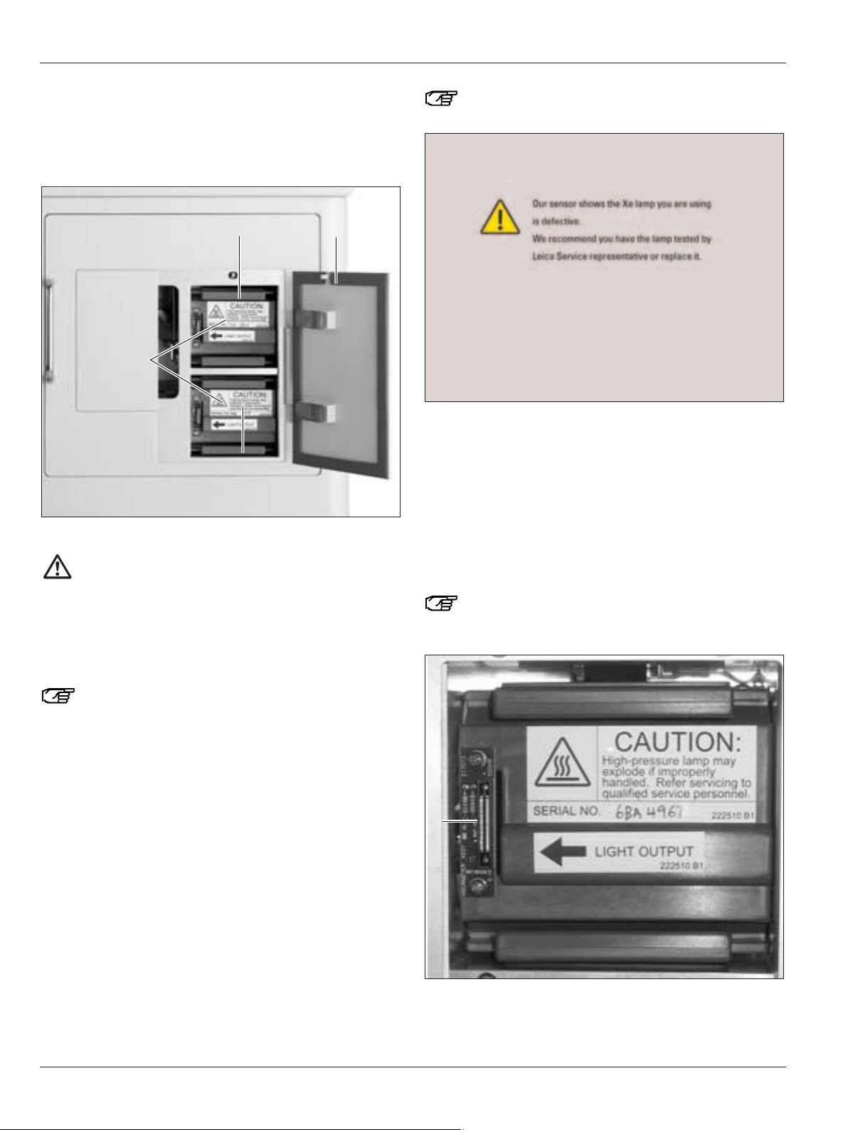
Care and maintenance
68
Leica M525 OH4 / Ref. 10 714 367 / Version -
Changing bulbs
➩Open the access door (2) for lamp inserts.
The illumination push-button (item 2, page 7) flashes orange.
Caution 25
Danger of skin burns!
The lamp insert is very hot.
➩Before changing the lamp, make sure that the lamp
insert has cooled down.
➩Remove the defective lamp insert (1 or 3) and install a new
lamp insert (spare part no. 10 448 022).
When installing the lamp insert, make sure that the
arrow (4) is pointing to the left.
➩Close the access door.
The illumination push-button (item 2, page 7) lights up green.
A dialog window opens when the lamp power drops
below the recommend minimum level.
➩Press the "Close" button.
The dialog window is closed.
➩Replace defective lamps.
Checking the timer for the xenon lamp
A timer window (5) for the xenon lamp is located on the main
illumination fitting. It displays the operating hours of the xenon
lamp.
We recommend that a xenon lamp with a remaining
useful life of 10% be replaced before commencing an
operation.
5
12
4
3
Page 71

Care and maintenance
69
Leica M525 OH4 / Ref. 10 714 367 / Version -
Changing fuses
Range 220V–240V: two 8A fuses, slow blow
Range 100V–120V: two 10A fuses, slow blow
➩Remove the cover (1) with a screwdriver.
➩Remove the fuses (2) from their receptacles and replace
them.
2
1
Page 72

70 Leica M525 OH4 / Ref. 10 714 367 / Version -
Notes on reprocessing of resterilizable
products
Products
Reusable products supplied by Leica Microsystems (Schweiz)
AG such as rotary knobs, objective protective glasses and
capping pieces.
Limitation of reprocessing:
For the medical devices used on patients suffering from
Creutzfeldt Jacob Disease (CJD) or suspected of having CJD or
variant CJD, the local statutory requirements have to be met.
Normally resterilizable products used on this group of patients
are to be eliminated without risk by incineration.
Occupational safety and health protection
Particular attention must be paid to the occupational safety and
health protection of the persons responsible for preparing contaminated products. Current regulations of hospital hygiene and
prevention of infection must be observed in the preparation,
cleaning and disinfection of the products.
Limitation of reprocessing
Frequent reprocessing has little effects on these products.
The end of the product life cycle is usually determined by wear
and year and damage through use.
Instructions
Workplace
Remove surface contamination with a disposable cloth / paper
cloth.
Storage and transport
No special requirements.
It is recommended to perform the reprocessing of a product
immediately following its use.
Preparation for cleaning
Remove the product from the Leica M525 OH4 surgical
microscope.
Cleaning: manual
Equipment: running water, rinsing agent, spirit, micro-fiber cloth
Procedure:
1. Rinse surface contamination off of the product (temp. <40°C).
Use some rinsing agent depending upon degree of
contamination.
2. If the optics is heavily contaminated, e.g. finger marks, fat
streaks etc., use spirit for cleaning.
3. Dry off products, except for optical components, with a
disposable cloth/paper cloth. Dry off optical surfaces with a
micro-fiber cloth.
Cleaning: automatic
Equipment: Cleaning/disinfecting device
It is not recommended to clean products with optical
components in a cleaning/disinfecting device. In addition,
optical components must not be cleaned in ultrasonic baths in
order to prevent damage.
Disinfection
The alcohol disinfection solution "Mikrozid, Liquid" may be used
in accordance with the instructions on the label.
Please note that optical surfaces must be rinsed thoroughly
with fresh drinking water, followed by fresh demineralized
water, after disinfection. The products must be dried thoroughly
before the subsequent sterilization.
Maintenance
No special requirements.
Control and functional test
Check the snap-on behavior of rotary knobs and CAN handles.
Packaging
Separate: A standard PE bag may be used. The bag must be
large enough for the product so that the closure is not under
tension.
Sterilization
See Table 1
Storage
No special requirements.
Additional information
None
Contact information of manufacturer
Address of local agent
Leica Microsystems (Schweiz) AG verified that the
aforementioned instructions for the preparation of a product
are suitable for its reuse. The processing person is responsible
for reprocessing with the equipment, materials and personnel
and for achieving the desired results in the reprocessing installation. In general, this requires validations and routine monitoring of the process. Every deviation from the supplied
instructions should also be examined carefully by the
processing person to determine effectiveness and possible
detrimental consequences.
Care and maintenance
Page 73

Care and maintenance
71
Leica M525 OH4 / Ref. 10 714 367 / Version -
Table 1: Sterilization
Permissible sterilization methods
Steam (autoclave) Ethylene oxide
Item no. Designation 134°C, t > 10min. max. 60°C
10180591 Clip-on handle X
10428328 Rotary knob, binoc. tube T X
10384656 Rotary knob, transparent X
10443792 Lever extension X
10429792 Capping piece, slit lamp X
10445368 Cover, binoc. tube 0–180° X
10445289 Handswitch holder X
10446058 Protective glass, multifoc. obj. X
1)
10446469 Objective protective glass Leica M680 X
1)
10446467 Objective protective glass Leica M840/M841 X
1)
10443714 Rotary ring, objective 0° X
10445341 Handle for Leica M655. sterilizable X
10445549 Handle for Leica M695 X
10445340 Cap for Leica M655/M695. sterilizable X
1)
Products with optical components can be steam-autoclaved using the conditions listed above. However, this may lead to the
formation of a layer of dots and streaks on the glass surface, which may reduce the optical performance.
Page 74

Care and maintenance
72
Leica M525 OH4 / Ref. 10 714 367 / Version -
General faults
If the equipment is no longer operating properly,
please consult your Leica representative.
Fault Cause Remedy
The swing arm is not correctly
balanced.
A cable is sticking.
Leica M525 OH4 locked.
A cable connection has come loose.
Incorrect assignment entered at control
unit.
The fiber optic cable has come loose.
Main illumination and/or backup
illumination defective.
Eyepiece are not mounted correctly.
Diopters not set correctly.
Swing arm is not correctly balanced.
Cables are not correctly laid or have
slipped out of position and exert force on
the system (poss. additional video cable).
Leica M525 OH4 was balanced in
a locked state.
Automatic balancing was not completed.
The microscope tilts when you press
the "All Brakes" button.
The microscope cannot be moved or
moved only with a great deal of effort.
Functions cannot be operated with the
footswitch or the control on the CAN
handles.
No light in the microscope.
The image remains unfocussed.
The microscope or the swing arm moves
up/down or rotates by itself.
Microscope and swing arm are difficult
to move or cannot be moved at all.
➩Balancing the swing arm
(see page 27).
➩Re-lay the affected cable.
➩Release the lock (see page 22).
➩Check the power cable.
➩Check the footswitch connection.
➩Change the assignments on the control
unit.
➩Check the optical fiber connection.
➩Switch to different light source
(see page 40).
➩Screw in the eyepiece completely.
➩Perform diopter correction exactly
as instructed (see page 24).
➩Balance the Leica M525 OH4
(see page 27).
➩Lay the cable in accordance with the
installation instructions and provide a
strain relief.
➩Release the lock (see page 22) and
balance the Leica M525 OH4
(see page 27).
➩Make sure that the microscope is in
position B (see page 30).
➩Press the push-button for Auto
Balance again.
Page 75

What to do if...?
73
Leica M525 OH4 / Ref. 10 714 367 / Version -
What to do if...?
Fault Cause Remedy
Automatic balancing cannot
be performed.
Zoom cannot be adjusted electrically.
No XY movements are possible at one of
the two CAN handles.
The microscope has not been balanced
exactly in the B-axis.
The push-button for automatic balancing
is flashing, but the acoustic signal is not
sounding (nothing is happening).
Swing arm cannot be moved.
The stand of the Leica M525 OH4 moves.
The range of movement of the
Leica M525 OH4 is limited
(swing, tilt, rotate, XY movement).
Leica M525 OH4 is not correctly
balanced.
Microscope is tilted at too great an
angle.
Failure of the zoom motor.
No XY movements have been set in
the control unit for the CAN handles.
Installed accessory was not turned
back to the working position when
balancing the B axis.
Balancing process still not complete.
Swing arm locked in position.
Footbrake not applied.
Cable laid too tightly.
Video camera was not correctly
mounted and touches the swing arm.
Position of accessory was changed
after balancing.
➩Align A/B axes on microscope
in parallel (see page 30).
➩Repeat automatic balancing
procedure.
➩Press the Zoom rotary button.
➩Set the zoom by turning the button
(see page 41).
➩Set the joystick to XY movement
(see page 50).
➩Balance the B-axis again.
Make sure that the accessory is turned
back to the working position when
balancing the B-axis (see page 28).
Perform intraoperative B/C balancing
(see page 30).
➩Rotate the microscope to the B-position
and press the Autoblance push-button.
➩Release the lock (see page 22).
➩Lock the footbrake in position (see page 35).
➩Re-lay the cable (see assembly instructions
Leica M525 OH4).
➩Mount the video camera correctly.
➩ Balance the Leica M525 OH4
(see page 27).
➩Perform intraoperative AC/BC balancing
of the Leica M525 OH4 (see page 30).
Page 76

74 Leica M525 OH4 / Ref. 10 714 367 / Version -
Fault Cause Remedy
TV, photography
Fault Cause Remedy
Leica M525 OH4 cannot be balanced.
Focus on microscope cannot
be adjusted.
The image appears shaded through the
microscope at the edges and the
illumination field is outside the
field of vision.
The weight disk which you are using on
the D-axis cannot balance installed
accessories.
Leica M525 OH4 was balanced in the
transport position.
Multifocus switch is "on".
Accessories not installed exactly.
➩Changing the weight disk on the D axis
(see page 33).
➩Move the Leica M525 OH4 out of the
transport position and balance it again.
➩Switch off the multifocus (see page 42).
Exception: you are using a laser
micromanipulator which has this function
as a safety precaution.
➩Install the accessories exactly in
the holders (see page 22).
Photographs/TV pictures unfocussed.
The photographs have a blue tone.
Microscope or Zoom Video Adapter
not precisely focussed.
Zoom Video Adapter is not set parfocal.
An incorrect film was used.
➩Focus precisely, insert graticule if
necessary.
➩Perform diopter correction exactly
as instructed.
➩Set the Zoom Video Adapter
parfocal as instructed.
➩Load daylight film.
Page 77

What to do if...?
75
Leica M525 OH4 / Ref. 10 714 367 / Version -
Error messages on the control unit
Fault Cause Remedy
"Check lamp 1/2" Lampe 1/2 is defective. Check and replace defective
lamp 1/2 after surgery.
"Device not present" A cable connection has loosened Contact your Leica represantative.
or is defective.
"No Connection to MDRS3" A cable connection has loosened Chek connection cable.
or is defective.
"Rear load too high" Mounted accessories cannot Reduce Load on back side of
be be balanced. optics carrier.
"Front load too high" Mounted accessories cannot Reduce Load on front side of
be be balanced. optics carrier.
"Rear load too high" Mounted accessories cannot Reduce Load on back side of
be be balanced. optics carrier.
"Front load too high" Mounted accessories cannot Reduce Load on front side of
be be balanced. optics carrier.
"Left hand side load too high" Mounted accessories cannot Reduce Load on left side of
be be balanced. optics carrier.
"Rught hand side load to high" Mounted accessories cannot Reduce Load on right side of
be be balanced. optics carrier.
"Too many counterweight wheels Wheel counterweight used on the Change wheel counterweight on
at D axis" D axis cannot compensate for the the D axis (see page 34)
mounted accessories
"Too less counterweight wheels Wheel counterweight used on the Change wheel counterweight on
at D axis" D axis cannot compensate for the the D axis (see page 34)
mounted accessories
"Illumination unit not closed" Access hatch for lamp inserts Close access hatch and lock
is not closed.Pushbutton for with rotary knob.
illumination flashes.
"Microscope-Device-Controller Contact your Leica represantative.
not present"
Page 78

Technical data
76
Leica M525 OH4 / Ref. 10 714 367 / Version -
Electrical data
Power connection for 1600 VA 50/60 Hz
Leica M525 OH4 100 V (+10%/–15%)
120 V (+10%/–15%)
220 V (+10%/–15%)
240 V (+10%/–15%)
Protection class Class 1
Leica M525
Microscope
Magnification 6:1 zoom, motorized
Working distance 207mm – 470mm, variable through
motorized multifocal lens, continuously adjustable;
manually adjustable override
Focusing Motorized via multifocal lens;
manually adjustable
Eyepiece Wide-field eyepieces for spectacle
wearers 10x and 12.5x
dioptric settings ±5 with adjustable
eye cup
Objective Multifocal lens; 207–470mm
variable working distance, with
optional WD extender lens
Illumination Illumination system specially
developed for microsurgical applications;
continuously adjustable
illumination field diameter with
Gauss-shaped light distribution.
Continuously adjustable brightness
at constant color temperature
AutoIris™ Built–in automatic zoom-
synchronized illumination field
diameter, with manual override and
reset feature
Main light source High performance 300 Watt xenon
arc-lamp through fiber optic
Emergency lamp 300 Watt xenon arc-lamp on
separate electrical system
BrightCare™ Safety technology for the working
distance synchronized to light
control
Optical data
Magnification range 1.2x – 12.8x with 10x eyepiece
Field of view (dia. in mm) 16.5mm – 180mm with 10x eyepiece
Microscope carrier
Rotation of optics 540°
Lateral tilt 50° to left / 50° to right
Inclination tilt –30° / +120°
XY speed Zoom linked XY speed
Balancing A,B,C and D axes fully automatic,
each can be corrected manually
Intraoperative AC/BC button for automatic
balancing intraoperative balancing of A&C
axes and for B&C axes
Brakes 1 brake for A/B axis
1 brake for C axis
Indicator LED for Fluorescence mode status,
LED for Video record status
Accessories
Leica ULT500 180° stereo observer,
Main/Assistant surgeon 40% each
beam path
Assistant /Video on selectable side
20% each beam path
Dual stereo attachment Main surgeon 70% / Assistant 30%
Second observer Stereo attachment for second
observer to beam splitter
Beam splitter 50% / 50%, 70% / 30%
Binocular tube Variable angle 30° – 150°,
variable angle 0° – 180°
Video Adapter 3:1 zoom,
35mm – 100mm focal length,
c-mount,
with fine focus
Imaging Leica DI C500 high resolution true
color dual imaging module for cor-
related and non correlated data
display
Asepsis Sterilizable protective glass cover
for the objective, sterilizable
components for various controls,
commercially available drapes
Laser Various commercially available
lasers and laser shutters can be
attached
Page 79

Technical data
77
Leica M525 OH4 / Ref. 10 714 367 / Version -
IGS
Interface / Compatibility Open architecture for IGS systems
Fluorescence
Vascular Fluorescence Optional Leica FL800 is available in
USA, EU, and most countries
Oncology Fluorescence Optional Leica FL400 available in
EU and some other countries
(Please check the status of
approval with your Leica
representative).
Floor stand
Type Floor stand with six
electromagnetic brakes
Base 720mm x 720mm with four 360°
rotatable casters with 130mm
diameter each, one central single
step foot brake
Balancing New "no brake release" Auto-
Balance:
One button / two push for complete
automatic balancing of stand and
optics
Intraoperative Balancing AC/BC button for automatic
intraoperative balancing of the AC
axis and for BC axis
Swingarm Patented advanced movement sys-
tem for perfect balance in six axes,
new vibration damping technology
Floorstand control unit New generation touch panel tech-
nology.
The latest electronics control for
the continuous governing of all
motor functions and the light
intensity.
Data shown by means of LCD.
Built-in BrightCare™ technology
for the working distance
synchronized light control.
ISUS ™ Intelligent Setup System,
Menu selection based on unique
software for user-specific configuration, with built-in electronic autodiagnosis and user support.
Control unit stand Software independent hard keys
for illumination and auto-balancing.
Indicator for Main / backup
illumination and Fluorescence
modes,
Open architecture for future
software developments.
Light source Dual Xenon arc-lamp illumination
system and built in automatic lamp
quick changer
Controls 10 function pistol grips for zoom,
focus, all-free release of six
brakes, side button for userdefined brakes, motorized lateral
tilt and inclination (XY) or
Leica DI C500 functions. Except for
the all-free button all functions are
freely programmable.
Mouthswitch for releasing the user
defined brakes
12 function foot control and
handswitch
Integration of Prepared for integration of
documentation Video- and digital recording
systems.
Open architecture
Connectors Numerous built-in connectors for
Video, IGS and control data
transfer, Internal Power 12 VDC,
19 VDC and AC connections
Carrier for monitor 700mm long and flexible arm with
4 axis for rotation and inclination to
carry optional video monitor
Materials All solid metal construction
Surface coating System Coated with antimicrobial paint
Minimum height In park position 1945mm
Range Cantilever Max. 1925mm
Load Min. 6.7kg and max.
12.2kg of accessories to the
microscope
Weight Approx. 320kg with full load
Page 80

Technical data
78
Leica M525 OH4 / Ref. 10 714 367 / Version -
Ambient conditions
In use +10°C to +40°C
+50°F to +104°F
30% to 95% rel. humidity
500mbar to 1060mbar
atmospheric pressure
Storage –40°C to +70°C
–40°F to +158°F
10% to 100% rel. humidity
500mbar to 1060mbar
atmospheric pressure
Standards fulfilled
Conformity CE • Directive 93/42/EEC concerning
medical devices: Class I, in
conformity with Annex IX,
Regulation 1, with reference to
Regulation 10 and 12 of the
directive.
• Medical electric equipment,
Part 1: General requirements
for safety IEC 60601-1;
EN 60601-1; UL60601-1;
CAN/CSA-C22.2 NO. 601.1-M90
• Electromagnetic compatibility
IEC 60601-1-2; EN 60601-1-2
According to the SQS Certificate,
the Business Unit SOM, within
Leica Microsystems (Schweiz)
AG, holds the management
system certificates for the
international standards
ISO 9001:2000 /ISO 13485:2003 and
ISO 14001:2004 relating to quality
management, quality assurance
and environmental management.
Limitations of use
The Leica M525 OH4 may be used only in closed rooms and
must be placed on a solid floor.
Page 81

Technical data
79
Leica M525 OH4 / Ref. 10 714 367 / Version -
List of weights of balanceable configurations
Minimum US standard Maximum Maximum
specification specification specification
Fluorescence
Leica Designation Unit Qty. Gross Qty. Gross Qty Gross Qty. Gross
Art. No. weight weight weight weight weight
(kg) (kg) (kg) (kg) (kg)
10446570 Counterweight, M500 2.900 1 2.900 0.000 0.000 0.000
10455349 30° rotary ring 0.184 1 0.184 0.000 0.000 0.000
10446058 Multifocal protective 0.017 1 0.017 1 0.017 1 0.017 0.000
glass
10446587
Binocular tube, straight,
0.795 0.000 0.000 0.000 0.000
T, Type II
10446797 Binocular tube 0.795 2 1.590 3 2.385 3 2.385 2 1.590
tiltable, 30–150°
10446574 Binocular tube 0.700 0.000 0.000 0.000 0.000
tiltable, T, Type II
10446485 Eyepiece size 10x/21B, 0.100 4 0.400 6 0.600 6 0.600 6 0.600
Type II
10446482 Beam splitter M500, 0.360 1 0.360 0.000 0.000 0.000
50/50% light distribution
10446475 Stereo assistant's 0.920 1 0.920 1 0.920 1 0.920 1 0.920
attachment, M500
10446573 Binocular tube, tiltable, 1.400 0.000 0.000 0.000 1 1.400
0–180°, T, Type II
10446592 Zoom video adapter 0.720 1 0.720 1 0.720 1 0.720 0.000
Video camera 0.360 1 0.360 1 0.360 1 0.360 0.000
10446852 DI-Color Module 4.140 0.000 0.000 1 4.140 1 4.140
(DI C500)
10446854 Ultra Observer (ULT500) 3.020 0.000 1 3.020 0.000 0.000
10713669 NIR Dual Video Adapter 1.240 0.000 0.000 0.000 1 1.240
incl. objective
UV camera handle 0.100 0.000 0.000 0.000 1 0.100
10713897 Sony NIR camera 0.040 0.000 0.000 0.000 1 0.040
10713667
10713680 Observation 0.500 0.000 0.000 0.000 1 0.500
filter module
10713648 FL illumination module 0.840 0.000 0.000 0.000 1 0.840
incl. adapter plate
10446469 M680 sterile glass 0.060 0.000 0.000 0.000 1 0.060
Gross weight 7.451 8.022 9.142 11.430
Page 82

80 Leica M525 OH4 / Ref. 10 714 367 / Version -
Illustrations of measure
±270¡
±50¡
±50¡
±40¡
±360¡
+120¡
-30¡
Technical data
Page 83

Technical data
81
Leica M525 OH4 / Ref. 10 714 367 / Version -
1200
max. 1925
720 x 720
2685
1945
Page 84

Technical data
82
Leica M525 OH4 / Ref. 10 714 367 / Version -
1180
1785
430
Page 85

Technical data
83
Leica M525 OH4 / Ref. 10 714 367 / Version -
Page 86

Notes
84
Leica M525 OH4 / Ref. 10 714 367 / Version -
Page 87

Notes
85
Leica M525 OH4 / Ref. 10 714 367 / Version -
Page 88

Leica Microsystems (Schweiz) AG
Business Unit SOM
Max Schmidheiny-Strasse 201
CH-9435 Heerbrugg
Telephone +41 71 726 33 33
Fax +41 71 726 32 19
www.leica-microsystems.com
Illustrations, descriptions and technical data are not binding and may be changed without notice.
Printed on paper made of chlorine free pulp with a high percent recycled fiber content.
10 714 367en/- • © Leica Microsystems (Schweiz) AG • CH-9435 Heerbrugg, 2006 • Printed in Switzerland – X.2006 – RDV
Leica Microsystems – the brand
for outstanding products
Leica Microsystems’ mission is to be the world’s first-choice provider of innovative
solutions to our customers’ needs for vision, measurement and analysis of microstructures.
Leica, the leading brand for microscopes and scientific instruments, developed from
five brand names, all with a long tradition: Wild, Leitz, Reichert, Jung and Cambridge
Instruments. Yet Leica symbolizes innovation as well as tradition.
Leica Microsystems – an international company
with a strong network of customer services
Australia North Ryde, NSW Tel. +61 2 8870 3500 Fax + 61 2 9878 1055
Canada Richmond Hill Tel. + 1 905 762 2000 Fax +1 905 762 8937
China Beijing Tel. + 86 10 684 92 698 Fax +86 10 684 92 965
Denmark Herlev Tel. + 45 4454 0101 Fax +45 4454 0111
France Rueil-Malmaison Cédex Tel. +33 1 473 285 85 Fax +33 1 473 285 86
Germany Bensheim Tel. +49 6251 136 0 Fax +49 6251 136 155
Hong Kong Tel. +85 22 56 46 699 Fax +85 22 56 441 63
Italy Milan Tel. + 39 0257 4861 Fax +39 0257 40 3273
Japan Tokyo Tel. +81 3 5421 2803 Fax +81 3 5421 2891
Korea Seoul Tel. +82 2 514 65 43 Fax + 82 2 514 65 48
Portugal Lisbon Tel. +35 1 21 388 9112 Fax + 35 1 21 385 4668
Singapore Tel. + 65 6779 7823 Fax +65 6773 0628
Spain Barcelona Tel. +34 93 494 95 30 Fax +34 93 494 95 32
Switzerland Glattbrugg Tel. +41 44 809 34 34 Fax +41 44 809 34 44
United Kingdom Milton Keynes Tel. +44 1908 66 66 63 Fax + 44 1908 609 992
USA Allendale/New Jersey Tel. +1 201 236 5900 Fax +1 201 236 5908
and representatives of Leica Microsystems
in more than 100 countries.
The companies of the Leica Microsystems Group operate internationally
in three business segments, where we
rank with the market leaders.
•
Microscopy Systems
Our expertise in microscopy is the basis
for all our solutions for visualization,
measurement and analysis of microstructures in life sciences and industry.
With confocal laser technology and
image analysis systems, we provide
three-dimensional viewing facilities and
offer new solutions for cytogenetics,
pathology and materials sciences.
•
Specimen Preparation
We provide comprehensive systems
and services for clinical histo- and
cytopathology applications, biomedical
research and industrial quality assurance. Our product range includes
instruments, systems and consumables
for tissue infiltration and embedding,
microtomes and cryostats as well as
automated stainers and coverslippers.
•
Medical Equipment
Innovative technologies in our surgical
microscopes offer new therapeutic
approaches in microsurgery.
Leica Microsystems (Schweiz) AG
Business Unit SOM
Max Schmidheiny-Strasse 201
Telephone +41 71 726 33 33
Fax +41 71 726 32 19
www.leica-microsystems.com
The Business Unit SOM, within Leica Microsystems (Schweiz) AG, holds the management system certificates for the international standards ISO 9001:2000 / ISO 13485:2003,
and ISO 14001:2004 relating to quality management, quality assurance and environmental
management.
 Loading...