

Page 1
Leica M501
User manual
10 711 785 – Version D
Page 2

Leica M501 / Ref. 10 711 785 / Version D
Page 3

Chapter Overview
1
Leica M501 / Ref. 10 711 785 / Version D
Introduction 3
Controls 7
Preparation for Operation 9
Use 19
Safety Notes 22
Care and Maintenance 32
Messages and Warnings 36
Technical data 37
Page 4

Table of Contents
2
Leica M501 / Ref. 10 711 785 / Version D
Page
Introduction
Design and function 4
Ceiling mounts 5
Controls
Control unit/lamp housing 6
Tilt head/focusing unit 6
Footswitch 6
Handswitch 7
Stand 7
Remote control for Leica Telescope Mount 7
Optics carrier 8
Binocular tube, eyepiece, tubes for second observer 8
Preparation for Operation
Retrofit the surgical microscope and balance
the swinging arm 9
Attach the binocular tube, eyepiece and objective 10
Set the interpupillary distance and eyepoint 12
Adjust for parfocality 12
Attach the adapter for accessories 13
Adjusting second-observer tube 14
Display/change the footswitch type 15
Switch the plus/minus movement directions
of the XY-unit 15
Disable/enable the function of the XY-Reverse button 15
Transport the surgical microscope 16
Position the surgical microscope at the OP stage 17
Sterile components 18
Setting the rest position on the Leica
Telescope Mount 18
Setting the rest position on the Leica Mini Mount 19
Use
Operating the surgical microscope 19
Positioning the microscope 20
Adjusting the focus 20
Adjusting the magnification 20
Adjusting the illumination 21
Setting the illumination type and the working distance
21
Safety Notes
Intended use 22
Directions for the operator of the instrument 22
Directions for the user of the instrument 22
Table 201 according to EN 60601-1-2:2001 23
Table 202 according to EN 60601-1-2:2001 24
Table 204 according to EN 60601-1-2:2001 25
Table 206 according to EN 60601-1-2:2001 26
Hazards associated with instrument use 27
Signs and labels 28
Page
Care and Maintenance
Changing the fuse 32
Changing the bulb 33
Inspecting the functioning 33
Notes on reprocessing of resterilizable products 34
Messages and Warnings
Ventilation 36
General malfunctions 36
Technical data
Electrical data 37
Microscope 37
Stands 38
Swing arm 39
Ambient conditions 39
Limitations of use 39
Standards 39
Dimensions 40
Page 5
Introduction
3
Leica M501 / Ref. 10 711 785 / Version D
User manual
This user manual contains important safety
precautions as well as information on using the
instrument (see the chapter "Safety notes").
Before attempting to set up the product, carefully
read through the user manual.
Product identification
The model code and serial number of your product are provided
on the nameplate found on the underside of the control unit.
Write this data into your User Manual and always refer to it
when you contact us or the service workshop regarding any
questions you may have.
Model: Serial No.:
Symbols used in this manual
The symbols used in this user manual
have the following meanings:
Warning regarding use hazard or
Warning noncompliant use that can lead to
serious injury or death.
Warning regarding use hazard or non-
Caution compliant use that can lead to minor
injury, but significant article, property
or environmental damage.
Useful information that can help the user
operate the product correctly and efficiently.
Request for action; here, you are
requested to take action.
➩
Page 6
Introduction
4
Leica M501 / Ref. 10 711 785 / Version D
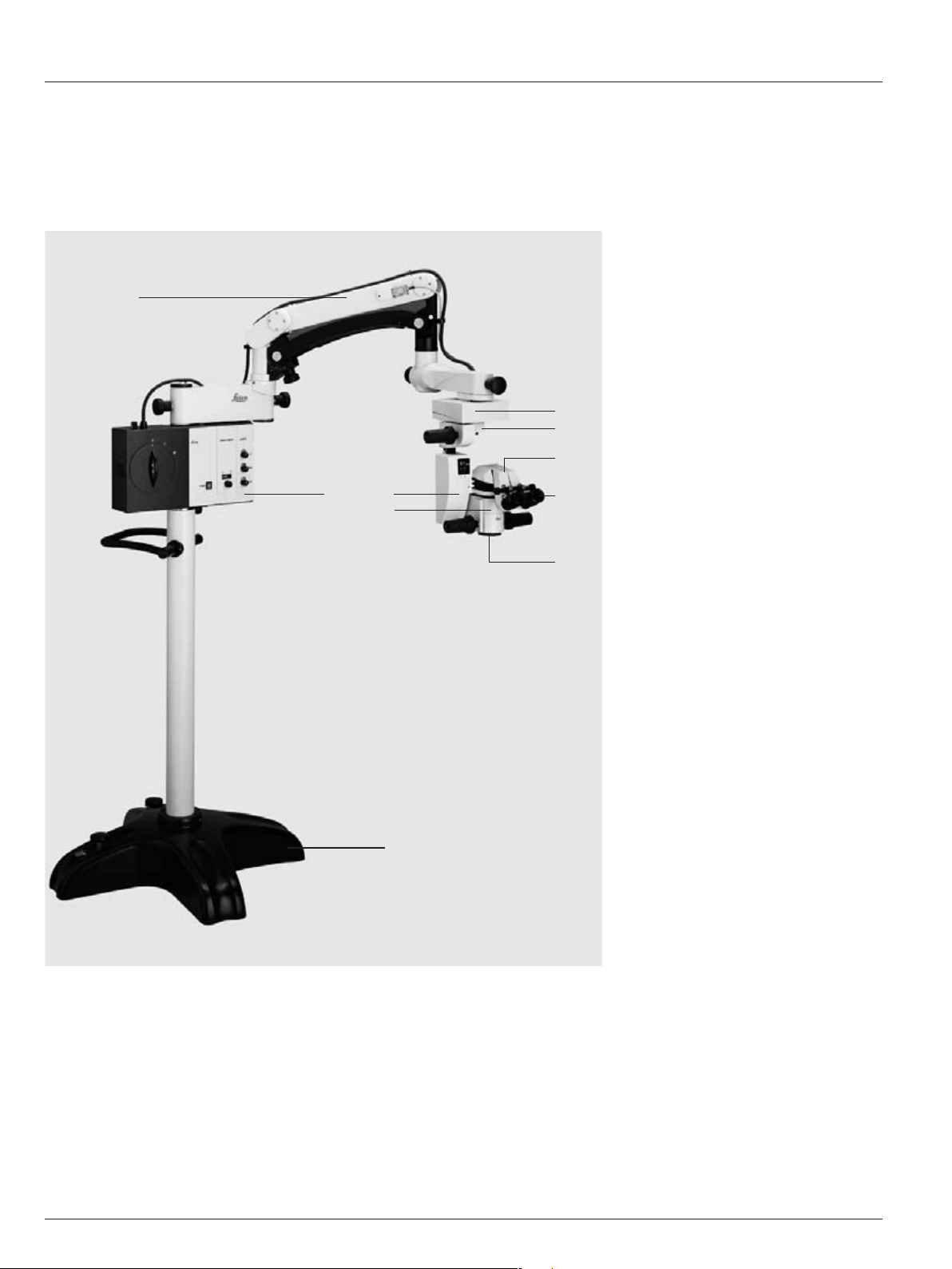
Design and function
1 Base
2 Control unit/lamp housing
3 Swing arm
4 XY-coupling (optional)
5 Tilt head
6 Focusing unit
7 Optics carrier
8 Binocular tube
9 Eyepieces
10 Objective
Floor stand
1
3
2
4
5
8
9
10
6
7
Page 7
Introduction
5
Leica M501 / Ref. 10 711 785 / Version D
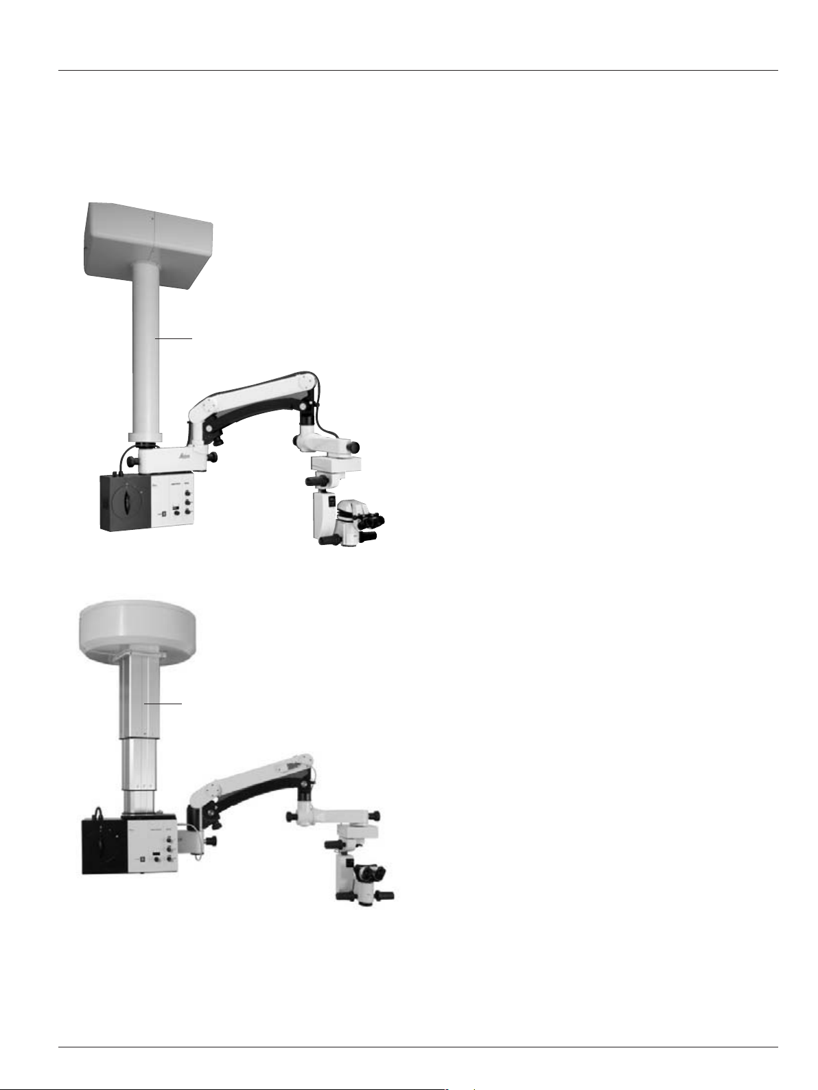
Ceiling mounts
1 Mini Mount ceiling mount
1
2 Leica Telescope Mount
2
Page 8
6 Leica M501 / Ref. 10 711 785 / Version D
Controls
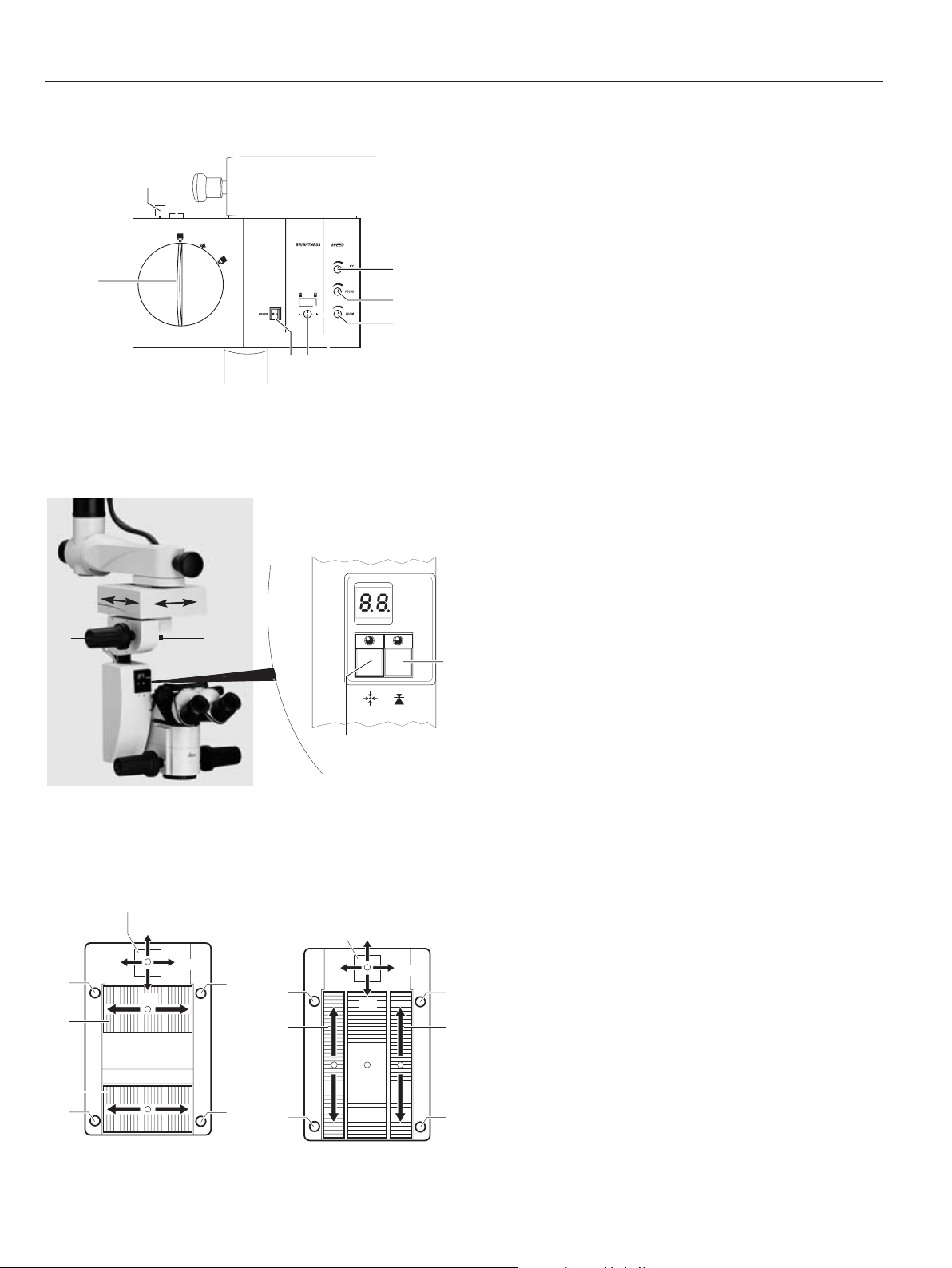
Control unit/lamp housing
2
1
•
XY-Reverse
Tilt head
3 Tilt head fine adjustment
4 Brake knob for rough adjusting
the tilt
Focusing unit
1 XY-unit reset button
2 Focus reset button
5
4
+
-
7
1
2
3
6
5
4
+
-
3
7
1
2
6
Footswitch
Cross pedal variant Vertical pedal variant
1 Main switch
2 Regulating knob for adjusting the travel speed of the
XY-coupling
3 Regulating knob for adjusting the travel speed of the
focus
4 Regulating knob for adjusting the travel speed of the
zoom
5 Regulating knob for adjusting the brightness of the
illumination
6 Rotary knob for changing filters
7 Turn grip for the quick-change lamp mount
1 XY adjustment
2 Focus up and down
3 Zoom up and down
4 Greater illumination
5 Less illumination
6 XY-Reverse
7 Microscope illumination on/off
Tilt head/focusing unit
3
4
6
7
2
3
4
51
Page 9
7Leica M501 / Ref. 10 711 785 / Version D
Controls
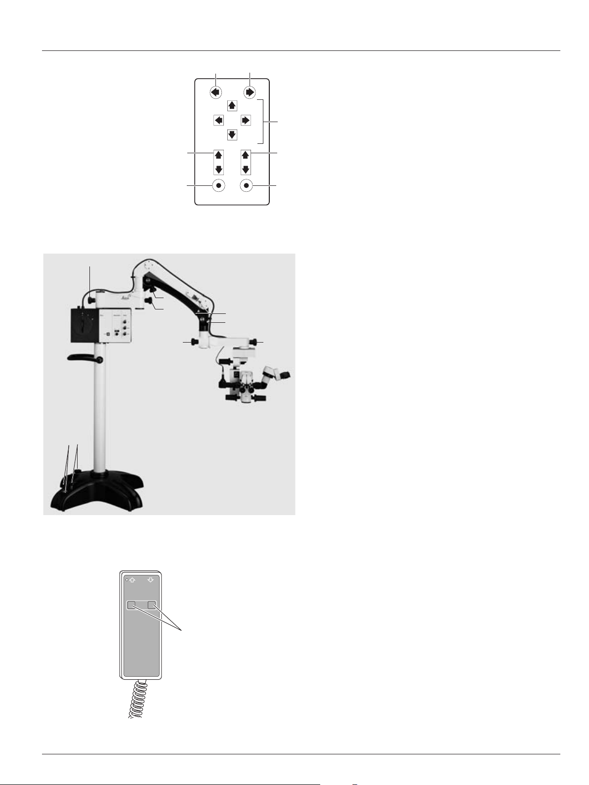
Handswitch
1 XY adjustment
2 Focus up and down
3 Zoom up and down
4 Greater illumination
5 Less illumination
6 XY-Reverse
7 Microscope illumination on/off
Stand
1 Footbrakes
2 Footbrake release lever
3 Articulation brakes
4 Balance turn knob
5 Safety hook
6 Retaining pin
3
33
3
4
1
2
5
6
Remote control for Leica Telescope Mount
1
1 Buttons for up/down movement
45
SL
XY
1
3
2
ZF
7
A
ML
6
Page 10
8 Leica M501 / Ref. 10 711 785 / Version D
Controls
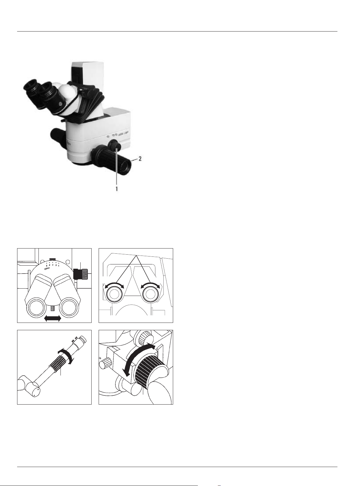
Optics carrier
1 Turn knob for fading ambient lighting
2 Handles
+5 -5 +5 -5
Binocular tube, eyepiece, tubes for second observer
1 Drive knob for adjusting the interpupillary distance
2 Diopter adjustment
3 Knurled ring for image correction
1
3
3
2
Page 11
9Leica M501 / Ref. 10 711 785 / Version D
Preparation for Operation
Lock the swing arm.
➩ Position the swing arm approximately horizontally.
➩ Pull out the retaining pin (3).
➩ Move the swing arm slightly up and down until the safety
hook (2) engages.
The swing arm is now locked.
Clean the optical accessories
➩ Inspect the eyepieces, objectives and any present photo and
TV-adapters for cleanliness.
➩ Remove dust and dirt.
Fitting accessories
➩ Equip the microscope ready for use with all necessary
accessories.
Balance the swing arm
➩ Hold the microscope firmly.
➩ Move the swing arm slightly up and down, at the same time
pushing the counterlever of the safety hook (2) upwards,
until the retaining pin clicks into position.
➩ See whether or not the microscope drifts.
Microscope drifts downwards:
➩ Turn rotary knob (4) clockwise.
Microscope drifts upwards:
➩ Turn rotary knob (4) counter-clockwise.
Warning 1
Risk of injury from the surgical microscope swinging
down!
➩Never rebalance or re-equip with the instrument over
the field of operation.
➩After re-equipping, always rebalance the swinging
arm.
Retrofit the surgical microscope and
balance the swinging arm
2
3
Page 12
10 Leica M501 / Ref. 10 711 785 / Version D
Preparation for Operation
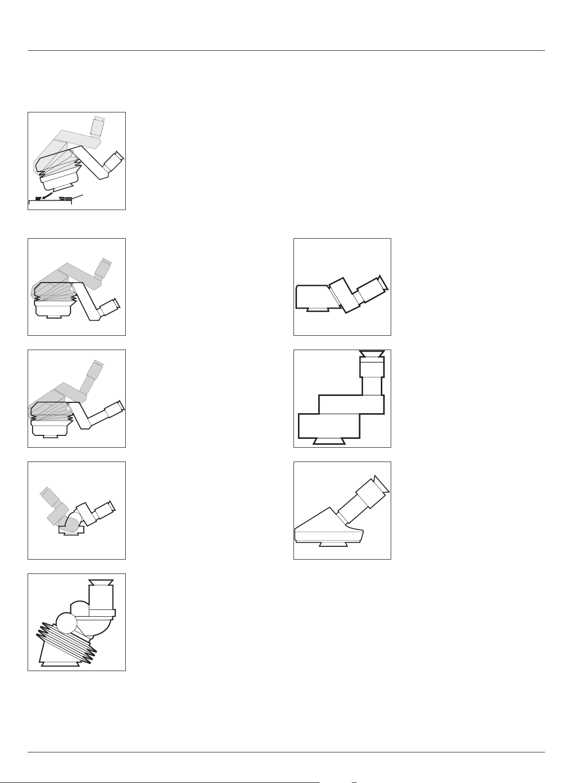
Attach the binocular tube, eyepiece and
objective
Binocular tube 10° – 50°, ultra low
Binocular tube 10° – 50°, low
Binocular tube with variable 180°
Binocular tube var. 30° – 150°
Attach the binocular tube
➩ Unscrew the clamping
screw (1).
➩ Push the binocular tube into
the dovetail ring.
➩ Tighten the clamping screw.
A range of options enables the Surgical Microscope to be
matched to the requirements of the task in hand.
Inclined binocular tube
Straight binocular tube
Inclined binocular tube 45°
Optional for use on the assistant’s
attachment
(no standard configuration)
1
Page 13
11Leica M501 / Ref. 10 711 785 / Version D
Preparation for Operation
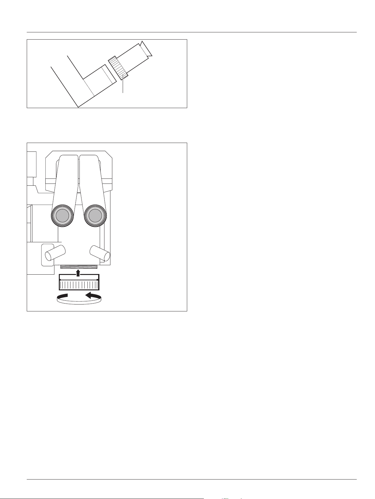
Fitting the eyepiece
➩ Set the eyepiece in place.
➩ Tighten the rotary ring (1).
Eyepieces
Eyepiece 10x/21B, adjustable
Eyepiece 12.5x/17B, adjustable
Fitting objectives
Objectives are screwed in on the microscope with right-hand
threading.
Objectives
Objective WD = 175mm APO
Objective f = 175mm
Objective f = 200mm
Objective f = 225mm
Objective f = 250mm
Objective f = 275mm
Objective f = 300mm
1
Page 14
12 Leica M501 / Ref. 10 711 785 / Version D12
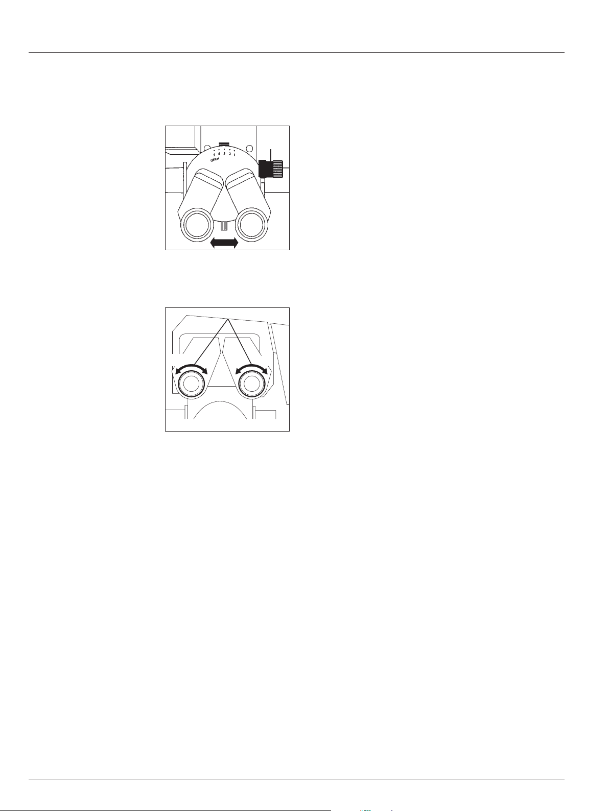
Preparation for Operation
The distance between both pupils and the desired contact with
the eyepieces are adjusted individually.
You can prepare the surgical microscope before the operation
using the data from a user table.
Regulate the interpupillary distance
➩ Turn the eyelenses on the eyepieces to "0" or set the dioptric
settings, if known.
➩ Set the magnification changer to step 10.
➩ Look through the eyepieces and adjust the tubes by hand
(for binocular tubes without drive knobs) or using the drive
knob (1) until you see a concentrically circular image field.
Set the interpupillary distance and
eyepoint
Adjust for parfocality
1
Adjusting the dioptric settings
Adjust the dioptric settings accurately for each eye separately;
only this method will ensure that the image will stay in
focus throughout the entire zoom range (parfocal).
1. Prepare the microscope
➩ Switch on the microscope at the control unit and place a flat
test object such as a piece of paper beneath the objective.
➩ Engage the highest brightness.
➩ Engage the lowest magnification.
➩ Displace the microscope so that the test object is visible in
the center of the field of view.
2. Focus on the test object
➩ Engage the highest magnification.
➩ Bring the test object into focus.
➩ Engage the lowest magnification.
3. Adjust the dioptric settings
➩ Adjust the dioptric settings for each eye in turn (2), so that
the image is seen in sharp focus.
➩ Engage the highest magnification.
➩ Refocus using motor-driven focusing.
➩ Engage the lowest magnification.
➩ Inspect the dioptric settings, readjusting them if necessary
so that both images are sharp.
4. Inspect the parfocality
➩ Zoom through the whole range, observing the test object.
The image sharpness must remain constant at all magnifications. If it does not, then repeat points 2 to 4 of this procedure.
+5 -5 +5 -5
2
Page 15

13Leica M501 / Ref. 10 711 785 / Version D
Preparation for Operation
Attach the adapter for accessories
Beam splitter with 50/50% observance
Stereo adapter for accessories
Adapter for Zeiss accessories on the Leica M501
Adapter for M600 accessories for the Leica M501
1
Attach the beam splitter/stereo adapter
➩ Unscrew clamping screw (1).
➩ Push the beam splitter/stereo adapter into the dovetail ring.
➩ Tighten the clamping screw.
Attach the adapter
➩Insert adapter into beam splitter.
➩ Tighten the rotary ring (1).
Page 16

14 Leica M501 / Ref. 10 711 785 / Version D
Preparation for Operation
Stereo attachment for second observer
The dual stereo attachments can be attached to the left or right
on the beam splitter and turned in any direction.
Tubes for second observer
The assistant turns the monocular tube for second observer in
the desired direction, adjusts his or her diopter on the eyepiece
and centers the image using the knurled ring.
Stereo attachment for second observer
The assistant turns his or her diopters in the desired direction,
centers the binocular tube horizontally, adjusts his or her
diopters and centers the image using the knurled ring.
Attach the stereo attachment/tube for second observer.
➩ Feed the stereo attachment/tube for second observer into
the beam splitter,
➩ Tighten the rotary ring (1).
1
Adjusting second-observer tube
Page 17

15Leica M501 / Ref. 10 711 785 / Version D
Preparation for Operation
Display/change the footswitch type
You can choose between cross pedal or vertical pedal variants
for the footswitch.
Display the footswitch type:
➩ Press the brightness regulating knob (3) for approx. 5 sec-
onds and release it.
The display bar (4) displays a small light for about three sec-
onds beneath the symbol (2) of the footswitch variant that is
currently selected
( or ).
Change the footswitch type:
➩ While the footswitch type is displayed (see above), briefly
press the brightness regulating knob.
This switches to the other footswitch variant and the type
that is now enabled is displayed for about 3 seconds.
Switch the + and – movement directions of the XY-unit (figure 1)
1
2
Use the "XY-Reverse" button (1) on the footswitch to reverse the
+ and – movement directions for the XY-unit to – and +.
➩ Press button (1), the small light (2) next to the zoom
indication (Figure 3) turns on.
➩ Pressing button (1) again reverses the XY function back to
normal and the small light (2) turns off.
This requires that this function is enabled (see below).
Disable/enable the function of the XY-Reverse button (figures 1 and 2)
To prevent this function from being triggered inadvertently, the
"XY-Reverse" button can be disabled.
Disable the function of the "XY-Reverse" button:
➩ Switch off the control unit/lamp housing at the power
switch (3).
➩ Press and hold button (1) of the footswitch.
➩ Switch on the control unit/lamp housing at the power switch
(3) and release button (1).
The "XY-Reverse" button is now disabled.
Enable the XY-Reverse button:
➩ Repeat the above steps.
2
•
XY-Reverse
3
43
2
-X
+Y
+X
+X
-Y
-X
-Y
+Y
1
1
3
Page 18

16 Leica M501 / Ref. 10 711 785 / Version D
Preparation for Operation
Caution 3
Surgical microscope can move without warning!
➩Always lock the footbrakes when you are not moving
the system.
Caution 2
The swinging arm can swing out uncontrollably!
➩Before transport, always set the instrument to the
transport configuration.
Transport position
Lock the swing arm:
➩ Position the swing arm approximately horizontally.
➩ Pull out the retaining pin (1).
➩ Move the swing arm slightly up and down until the safety
hook (2) engages.
The swing arm is now locked.
➩ Release the articulation brakes (3) and fold up the swing
arm.
➩ Set the surgical microscope in its transport position and lock
the articulation brakes.
Caution 4
Feet in lightweight shoes could become trapped
beneath the casing of the base!
➩Always push the instrument to displace it; never pull it.
Transport the surgical microscope and secure it in its setup
position
➩ Pull the power cable out of the socket.
➩ Step on the footbrake release lever (5) to release the foot-
brakes (6).
➩ Push the surgical microscope to its setup position using the
handle (4).
➩ Lock the footbrakes at the setup position.
Transport the surgical microscope
(floor stand only)
56
6
3
3
4
2
1
Page 19

17Leica M501 / Ref. 10 711 785 / Version D
Preparation for Operation
➩ Using the handle, transport the surgical microscope to the OP
stage and position it as needed for the operation.
➩Apply footbrake.
➩
Connect the power cable to the control unit/lamp housing (13).
➩ Connect the potential equalization to the control unit/lamp
housing (9).
➩ Connect the foot or handswitch to the control unit/lamp
housing (11).
CAN-Bus interface (10).
Service interface socket (12).
Optional Leica Telescope Mount
Position the surgical microscope at the
OP stage
Warning 5
Danger of fatal electrical shock!
➩Plug the surgical microscope only into a grounded
socket.
Caution 9
Danger of collision!
The surgical microscope can collide with nearby components, light fixtures, or the ceiling.
➩Check the danger area before moving the swing arm.
➩Move the ceiling mount upwards carefully, and note
the position of the ceiling and light fixtures.
Warning 8
Risk of injury from the surgical microscope being
lowered!
➩Never position the surgical microscope over the
patient while it is moving downwards.
➩To avoid collisions, watch the surgical microscope
while it is being lowered.
Move the telescope arm to the desired height:
➩ Press the button (1).
Raise the telescope arm
Lower the telescope arm
In continuous operation, the telescope may be operated for a maximum of 1 minute out of every 10.
After 2 minutes of uninterrupted operation, the built-in
temperature switch switches off the motor of the
Leica Telescope Mount.
1211109
13
1
Page 20

18 Leica M501 / Ref. 10 711 785 / Version D
Setting the rest position on the Leica Telescope Mount
➩ Swing the microscope away.
➩ Remove the sterile components.
➩ Switch off the power switch.
➩ Move the swing arm all the way upwards.
➩ Release the articulation brakes.
➩ Press the raise lift arm (2) button.
The Leica Telescope Mount moves upwards.
2
Caution 9
Danger of collision!
The surgical microscope can collide with nearby components, light fixtures, or the ceiling.
➩Check the danger area before moving the swing arm.
➩Move the ceiling mount upwards carefully, and note
the position of the ceiling and light fixtures.
Preparation for Operation
Attach the sterile components
Set for one operation
• 3 handles
• 3 drive knobs
The handles and drive knobs can be sterilized via steam or gas.
➩ Sterilize the handles and drive knobs.
➩ Place the sterile drive knobs onto the binocular tube and the
turn knob for fading ambient lighting.
➩ Place the sterile handles onto the optics carrier and the tilt
head.
1
1
1
1
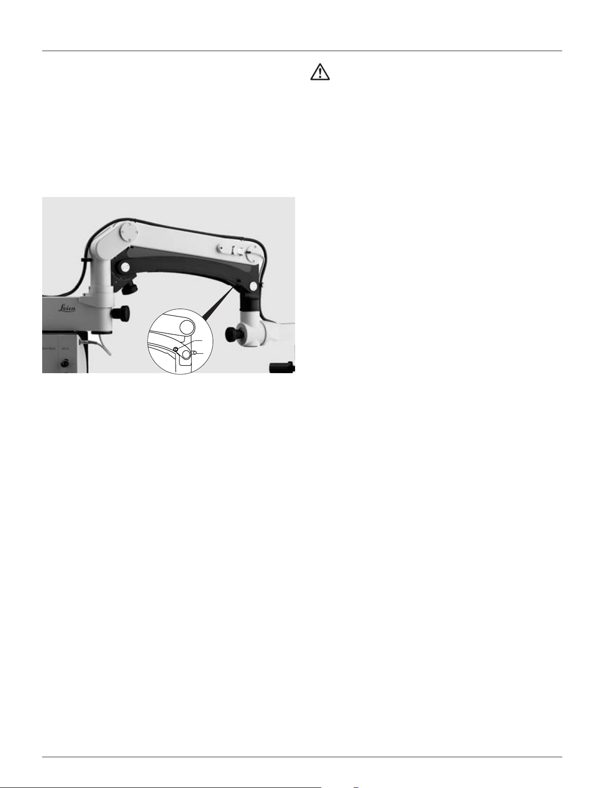
➩ Adjust the tilt of the footswitch. Screw the adjustable sup-
ports in or out.
➩ Check that all accessories are correctly connected and
securely attached.
➩ Release the articulation brakes and apply them lightly.
Make the joint easier to move:
➩ Release the joint brake (1).
Make the joint stiffer:
➩ Tighten the joint brake (1).
➩ Extend the swinging arm.
➩ Release the retaining hook on the swinging arm.
➩ Check the weight setting on the swinging arm by raising and
lowering the microscope and correct as necessary.
Caution 7
Danger of infection!
➩Leave sufficient space around the stand to ensure
that the sterile drape does not come into contact with
non-sterile components.
Page 21

19Leica M501 / Ref. 10 711 785 / Version D
Preparation before operation/Use
Operating the surgical microscope
1
➩ Switch on the power switch (1).
The XY-unit is driven to its middle position.
When the middle position is reached, the LED lights up.
The focus is driven at maximum speed to its home position
(1/3 up, 2/3 down). When the focus reset position is reached,
the LED lights up.
Basic settings:
When the Leica M501 is switched on at the power switch,
the zoom finds the position it was in when the unit was last
switched off.
The illumination for the surgical microscope turns on.
Setting the rest position on the Leica Mini Mount
➩ Swing the microscope away.
➩ Remove the sterile components.
➩ Switch off the power switch.
➩ Move the swing arm all the way upwards.
➩Swing the device out of the working area.
➩Tighten the articulation brakes.
Caution 10
Danger of collision!
The surgical microscope can collide with nearby components.
➩Check the danger area before moving the swing arm.
Page 22

20 Leica M501 / Ref. 10 711 785 / Version D
Use
Basic settings:
➩ Press the "Reset Focus" (2) button. The focus is driven at
maximum speed to its home position (1/3 up, 2/3 down).
When the focus reset position is reached, the LED (1) lights up.
Adjusting the focus
➩ Activate the button (9) on the foot or hand switch.
➩ Adjust the speed using the regulating knob (12) on the con-
trol unit/lamp housing.
11
12
13
Adjusting the focus
Adjusting the magnification
➩ Activate the button (10) on the foot or hand switch.
➩ Adjust the speed using the regulating knob (13) on the
control unit/lamp housing.
Position the microscope
8
9
8
9
10
10
Set the middle position:
➩ Press the "Reset X/Y-unit" key (3).
The XY-unit is driven to its middle position.
When the middle position is reached, the LED (4) lights up.
Coarse positioning
➩ Hold the microscope by the two handles (5) and position it.
Fine positioning
➩ Use foot or hand switch (8) to activate X/Y-unit.
➩ Adjust the travel speed of the XY-unit using the regulating
knob (11) on the control unit/lamp housing.
Rough tilt adjustment:
➩ Release the brake knob (7) and roughly adjust the tilt of the
microscope.
➩ Tighten the brake knob (7).
Fine tilt adjustment:
➩ Use the tilt fine adjustment (6) to accurately adjust the tilt of
the microscope.
1
2
3
4
6
5
Page 23

21Leica M501 / Ref. 10 711 785 / Version D
Use
➩ Adjust the brightness of the main illuminator using the regu-
lating knob (6) or the hand or footswitch. (1) = brighter,
(2) = darker. The brightness level is displayed on the display
bar (5).
➩ Turn the filter knob (4) until the correct filter is selected.
4
7
8
Adjusting the illumination
Setting the illumination type and the
working distance
➩ Adjust the approximate working distance by raising or
lowering the microscope using the handles (8).
➩ Turn counterclockwise (7) to fade out ambient lighting/6°
➛ Red reflex illumination/0° remains.
1 2
3
Switching microscope illumination on and off
Use button (3) to switch microscope illumination on and off.
Warning 6
Intensive light can injure eyes!
Light that is too intense can damage the retina, so
please:
➩Select short illumination times and low brightness
settings.
Warning 12
Protect the eyes of your patients!
➩The GG475 UV protection filter must be used to pro-
vide protection against light damage when using the
surgical microscope in ophthalmology.
56
Page 24

22 Leica M501 / Ref. 10 711 785 / Version D
Safety Notes
The Leica surgical microscope meets today’s state of the art of
technology. Nevertheless, hazards can occur during operation.
➩ For this reason, always observe the information in this User
Manual, especially the Safety Notes.
Intended use
• The Leica surgical microscope system is an optical instrument which uses magnification and illumination to improve
the display of objects. It can be applied for observation and
documentation and for human and veterinary medical treatment.
• The Leica surgical microscope may be used only in closed
rooms and must be placed on a solid floor or attached to a
strong ceiling or wall.
• The Leica M501 surgical microscope is subject to special
precautionary measures for electromagnetic compatibility.
It must be installed and put into operation in accordance
with the guidelines, manufacturer's declarations and
recommended safety distances (Table 201, 202, 204, 206
according to EN 60601-1-2:2001).
• Portable and mobile as well as stationary RF communications equipment can have a negative effect on the reliability
of the Leica M501 surgical microscope.
Directions for the operator of the
instrument
➩ Ensure that the surgical microscope is used only by persons
qualified to do so.
➩ Ensure that this user manual is always available at the place
where the surgical microscope is in use.
➩ Carry out regular inspections to make certain that the autho-
rized users are adhering to safety requirements.
➩ When instructing new users, do so thoroughly and explain
the meanings of the warning signs and messages.
➩ Assign individual responsibilities for starting, operating and
servicing the Leica Surgical Microscope and monitor the
observance of these responsibilities.
➩ Only use the surgical microscope if it is free of defects.
➩ Inform your Leica representative or Leica Microsystems
(Schweiz) AG, BU SOM, CH-9435 Heerbrugg, immediately if
you detect a product defect that could potentially cause
injury or harm.
➩ If you use accessories made by third-party manufacturers
with the Leica Surgical Microscope, be sure that each such
manufacturer confirms the safety-engineering, harmless
usability of the product and observe the product’s user
manual.
➩ Modifications to or service on the surgical microscope may
be carried out only by technicians who are explicitly authorized by Leica to do so.
➩ Only original Leica replacement parts may be used in servic-
ing the product.
➩ After service work or technical modifications, the unit must
be reconfigured with observance to our technical requirements.
➩ If the unit is modified or serviced by unauthorized persons, is
improperly maintained (as long as maintenance was not carried out by us), or is handled improperly, Leica will not
accept any liability.
➩ The influence on other devices by the Leica Surgical Micro-
scope has been tested in accordance with EN 60 601-1-2.
The system passed emissions and immunity test. Here, the
standard preventive measures and safety regulations pertaining to electromagnetic and other radiation had to be
observed.
Directions for the user of the instrument
➩ Follow the instructions described here.
➩ Follow the instructions given by your employer regarding the
organization of work and safety at work.
Page 25

Guidance and manufacturer’s declaration
23
Leica M501 / Ref. 10 711 785 / Version D
Manufacturer’s declaration of electromagnetic compatibility (EMC)
This "Guidance and manufacturer’s declaration" document is based on EN 60601-1-2:2001.
Table 201 from EN 60601-1-2:2001
Guidance and manufacturer’s declaration – electromagnetic emissions
The Leica M501 surgical microscope is intended for use in the electromagnetic environment specified below.
The customer or the user of the Leica M501 surgical microscope should assure that it is used in such an environment.
Emissions test Compliance Electromagnetic environment – guidance
RF emissions Group 1 The Leica M501 uses RF energy only for its internal function.
according to CISPR 11 Therefore, its RF emissions are very low and are not likely to cause any
interference in nearby electronic equipment.
RF emissions Class A The Leica M501 is suitable for use in establishments
according to CISPR 11 other than domestic and those directly connected to the public
low-voltage power supply network that supplies buildings used for
domestic purposes.
Harmonic Class A
emissions
IEC 61000-3-2
Voltage fluctuations/ according
flicker emissions
IEC 61000-3-3
Page 26

Guidance and manufacturer’s declaration
24
Leica M501 / Ref. 10 711 785 / Version D
Table 202 from EN 60601-1-2:2001
Guidance and manufacturer’s declaration – electromagnetic immunity
The Leica M501 surgical microscope is intended for use in the electromagnetic environment specified below.
The customer or the user of the Leica M501 surgical microscope should assure that it is used in
such an environment.
Immunity test IEC 60601 test level Compliance level
Electrostatic ± 6 kV ± 6 kV
discharge (ESD) contact contact
IEC 61000-4-2
± 8 kV air ± 8 kV air
Electrical fast ± 2 kV for ± 2 kV for
transient/ power supply lines power supply lines
burst
IEC 61000-4-4 ± 1 kV for input/ ± 1 kV for input/
output lines output lines
Surge ± 1 kV ± 1 kV
IEC 61000-4-5 differential mode differential mode
± 2 kV ± 2 kV
common mode common mode
Voltage dips, <5% UT (>95% <5% UT (>95%
short interruptions dip in UT) dip in UT)
and voltage variations on for 11/22cycle for 11/22cycle
power supply lines
IEC 61000-4-11 40% UT (60% 40% UT (60%
dip in UT) dip in UT)
for 5 cycles for 5 cycles
70% UT (30% 70% UT (30%
dip in UT) dip in UT)
for 25 cycles for 25 cycles
< 5% UT (>95% < 5% UT (>95%
dip in UT) dip in UT)
for 5 sec. for 5 sec.
Power frequency 3 A/m Not applicable
(50/60 Hz)
magnetic field
IEC 61000-4-8
Note: UT is the a.c. mains voltage prior to application of the test level.
Electromagnetic environment – guidance
Floors should be of wood, concrete or
ceramic tile. If floors are covered with synthetic material, the relative humidity should
be at least 30%.
Mains power quality should be that of a
typical commercial or hospital environment.
Mains power quality should be that of a
typical commercial or hospital environment.
Mains power quality should be that of a
typical commercial or hospital environment. If the user of the Leica M501 surgical
microscope requires continued operation
during power mains interruptions,
it is recommended that the Leica M501
surgical microscope be powered from an
uninterruptible power supply or a battery.
Page 27

Guidance and manufacturer’s declaration
25
Leica M501 / Ref. 10 711 785 / Version D
Table 204 from EN 60601-1-2:2001
Guidance and manufacturer’s declaration – electromagnetic immunity
The Leica M501 surgical microscope is intended for use in the electromagnetic environment specified below.
The customer or the user of the Leica M501 surgical microscope should assure that it is used in
such an environment.
Immunity test IEC 60601 test level Compliance level Electromagnetic environment – guidance
Portable and mobile RF communications
should be used no closer to any part of the
Leica M501 surgical microscope, including
cables, than the recommended separation
distance calculated from the equation applicable to the frequency of the transmitter.
Recommended separation distance:
Conducted RF 3 Vrms 3 Vrms d = 2.4 P
equipment 150 kHz to 80 MHz 150 kHz to 80 MHz
IEC 61000-4-6
Radiated HF 3 V/m 3 V/m d = 2.4 P
80 MHz to 2.5 GHz
IEC 61000-4-6 80 MHz to 2.5 GHz
Where Pis the maximum output power rating
of the transmitter in watts (W) according to
the transmitter manufacturer and d is the
recommended separation distance in
meters (m). Field strengths from fixed RF
transmitters, as determined by an electromagnetic site survey, should be less than the
compliance level in each frequency range.
Interference may occur in the vicinity of
equipment marked with the following symbol:
Note 1: At 80 MHz, the higher frequency range applies.
Note 2: These guidelines may not apply in all situations. Electromagnetic propagation is affected by
absorption and reflection from structures, objects and people.
a Field strengths from fixed transmitters, such as base stations for radio (cellular/cordless) telephones and land mobile radios,
amateur radio, AM and FM broadcast and TV broadcast cannot be predicted theoretically with accuracy. To assess the electromagnetic environment due to fixed RF transmitters, an electromagnetic site survey should be considered. If the measured
field strength in the location in which the Leica M501 surgical microscope is used exceeds the applicable RF compliance level
above, the Leica M501 should be observed to verify normal operation. If abnormal performance is observed, additional
measures may be necessary, such as reorienting or relocating the Leica M501.
b Over the frequency range 150kHz to 80MHz, field strengths should be less than 3V/m.
Page 28

Guidance and manufacturer’s declaration
26
Leica M501 / Ref. 10 711 785 / Version D
Table 206 from EN 60601-1-2:2001
Recommended separation distances between portable and mobile RF telecommunications equipment and
the Leica M501 surgical microscope
The Leica M501 surgical microscope is intended for use in an electromagnetic environment in which radiated RF
disturbances are controlled. The customer or user of the Leica M501 surgical microscope can help prevent
electromagnetic interference by maintaining a minimum distance between portable and mobile RF communication
equipment (transmitters) and the Leica M501 as recommended below, according to the maximum output power of the
communications equipment.
Separation distance according to frequency of transmitter in m
Rated maximum output 150 kHz to 2.5 GHz
power of transmitter W
d = 2.4 P in m
0.01 0.24
0.1 0.8
1 2.4
10 8.0
100 24.0
For transmitters rated at a maximum output power not listed above, the recommended separation distance d in meters (m) can
be estimated using the equation applicable to the frequency of the transmitter, where P is the maximum output powerrating
of the transmitter in watts (W) according to the transmitter manufacturer.
Note 1: These guidelines may not apply in all situations. Electromagnetic propagation is affected by
absorption and reflection from structures, objects and people.
Warning message:
Using accessories or cables other than those listed here or those permitted by the manufacturer of the Leica M501
surgical microscope may result in increased electromagnetic emissions or decreased immunity.
Warning message:
The Leica M501 surgical microscope may not be used while positioned directly next to other instruments.
If it is necessary to operate it in the vicinity of other instruments, the instrument should be monitored to ensure that it functions
properly in this arrangement.
Page 29

27Leica M501 / Ref. 10 711 785 / Version D
Safety Notes
Caution 3
Surgical microscope can roll away on its own!
➩Always lock the footbrakes when you are not moving
the system.
Caution 4
Feet in lightweight shoes could become trapped
beneath the casing of the base!
➩
Always push the instrument to displace it; never pull it.
Warning 5
Danger of fatal electrical shock!
➩Plug the surgical microscope only into a grounded
socket.
Caution 13
Burn hazard!
The lamp for the emergency illuminator can become
very hot.
➩Before changing lamps, ensure that the lamp has
cooled down.
Caution 14
You may sustain burns!
Lamps and mounts for holding illumination devices can
become very hot.
➩Before changing lamps, ensure that the lamp and the
mount have cooled down.
Caution 7
Danger of infection!
➩Leave sufficient space around the stand to ensure
that the sterile drape does not come into contact with
non-sterile components.
Warning 1
Risk of injury from the surgical microscope swinging
down!
➩Never rebalance or re-equip with the instrument over
the field of operation.
➩After re-equipping, always rebalance the swinging
arm.
Caution 2
The swinging arm can swing out uncontrollably!
➩Before transport, always set the instrument to the
transport configuration.
Warning 6
Intensive light can injure eyes!
Light that is too intense can damage the retina, so
please:
➩Select short illumination times and low brightness
settings.
Hazards associated with instrument use
Caution 10
Danger of collision!
The surgical microscope can collide with nearby
components.
➩Check the danger area before moving the swing arm.
Warning 11
Danger of fatal electrical shock!
➩Always unplug the power cable from the unit supply
socket before changing the fuse.
Warning 12
Protect the eyes of your patients!
➩The GG475 UV protection filter must be used to pro-
vide protection against light damage when using the
surgical microscope in ophthalmology.
Caution 9
Danger of collision!
The surgical microscope can collide with nearby
components, light fixtures, or the ceiling.
➩Check the danger area before moving the swing arm.
➩Move the ceiling mount upwards carefully, and note
the position of the ceiling and light fixtures.
Warning 8
Risk of injury from the surgical microscope being
lowered!
➩Never position the surgical microscope over the
patient while it is moving downwards.
➩To avoid collisions, watch the surgical microscope
while it is being lowered.
Page 30

28 Leica M501 / Ref. 10 711 785 / Version D
Safety Notes
Grounding reliability can
only be achieved when
EQUIPMENT is connected to
equivalent receptacle marked
"Hospital" or "Hospital Grade".
Leica Microsystems AG
CH-9435 Heerbrugg
MODEL LEICA M501
100V – 240V~ 50/60Hz
400VA
Form 2x T8.3A / 250V
Signs and labels
Type 10446644
S/N XXXXXXXXX
Caution 9
To prevent electric shock, do not remove cover.
No user serviceable parts inside.
Refer servicing to qualified service personnel only.
Page 31

29Leica M501 / Ref. 10 711 785 / Version D
Safety Notes
DO NOT OPEN AND
DAMAGE-HIGH PRESSURE!
GAS SPRING 10710287
Warning:
This system may only be used
with the gas spring 10710287
otherwise the instrument can fall over.
Page 32

30 Leica M501 / Ref. 10 711 785 / Version D
Safety Notes
Caution 1
You may sustain burns!
Mounts for the main illuminator can become very hot.
➩ Before changing lamps, ensure that the mount has cooled down.
Page 33

31Leica M501 / Ref. 10 711 785 / Version D
Safety Notes
Leica Microsystems AG
CH-9435 Heerbrugg
MODEL LEICA M501
230V~ 50 Hz
1400VA
S/N TTMMJJxxx - C
Leica Microsystems AG
CH-9435 Heerbrugg
MODEL LEICA M501
120V~ 60 Hz
1500VA
S/N TTMMJJxxx - C
Only one of the two signs, depending on
the power supply voltage.
Page 34

32 Leica M501 / Ref. 10 711 785 / Version D
Care and Maintenance
• Put a dust cover over the instrument during breaks in work.
• Keep accessories in a dust-free place when not in use.
• Remove dust with a pneumatic rubber pump and a soft
brush.
• Clean the objectives and eyepieces with special optics
cleaning cloths and pure alcohol.
• Protect the surgical microscope from moisture, fumes and
acids and from alkaline, caustic and corrosive materials.
Do not keep chemicals near the instrument.
• Protect the surgical microscope from improper handling.
Never install any other socket or unscrew the optical systems or mechanical parts unless expressly instructed to do
so in the instructions.
• Protect the surgical microscope from oil and grease.
Never oil or grease the guide surfaces or mechanical parts.
• Remove coarse debris with a moistened disposable cloth.
• To disinfect the surgical microscope, use preparations from
the group of surface disinfectants based on the following
substances:
- aldehyde,
- alcohol,
- quaternary
ammonia compounds.
The device is basically maintenance-free. To keep it reliable,
we recommend that you visually inspect the product for damage once a year and, as necessary, contact your service organization.
The ceiling mount must be serviced and maintained at certain
intervals.
Regularly, but at least once every 6 months
• Functional and visual inspection of the entire ceiling mount
by an authorized specialist.
Every 6 years
• Visual inspection of all cables by authorized professionals.
Every 12 years
• Thorough restoration and replacement of the cables.
Use only original spare parts for servicing.
Because they can potentially cause damage to materials, substances based on the following are not suited
for use with the system:
• halogen-separating compounds,
• strong organic acids,
• oxygen-separating compounds.
Follow the disinfectant manufacturer’s instructions.
It is recommended to conclude a service contract with
Leica Service.
1
1
2
3
▼
2 3
Warning 11
Danger of fatal electrical shock!
➩Always unplug the power cable from the unit supply
socket before changing the fuse.
➩The fuses are located in a fuse holder in the device power
socket (1, Figure 1).
➩Use a screwdriver (2, Figure 2) to press the fuse holder
(3, Figure 2) out in the direction indicated by the arrow, pull
it out completely by hand (Figure 3) and change the fuses.
➩Insert the fuse holder again and push it all the way in by
hand.
Changing the fuse
Page 35

33Leica M501 / Ref. 10 711 785 / Version D
Care and Maintenance
Changing bulb
1
36
Caution 13
You may sustain burns!
Lamps and mounts for holding illumination devices can become
very hot.
➩ Before changing lamps, ensure that the lamp and the mount
have cooled down.
To ensure that a replacement lamp is always available
should a bulb burn out, always replace defective bulbs
immediately after the operation.
➩ Turn the turn grip for the quick-change lamp mount (1) 30° to
the "Change Bulb" position and pull it out.
This automatically switches off the illumination.
➩ Pull the halogen lamp (4) and its mount (5) out of the holder
(2) (Figure 2).
➩ Put a new halogen lamp into the mount.
➩ Push the halogen lamp with the mount into the holder until
you feel it snap into place.
➩ Push the turn grip for the quick-change lamp back into the
housing.
The nib (6) on the turn grip for the quick-change lamp mount
has to be inserted into the notch (3) in the housing.
➩ Turn the turn grip for the quick-change lamp mount to the
lamp symbol ( ).
This automatically switches illumination back on.
1
2
3
Illumination
➩ Switch on the main power switch. The main illuminator
switches on.
➩ Switch to auxiliary illumination.
Auxiliary illumination lights up.
➩ Switch back to the main illuminator and switch illumination
off.
Foot/hand switch
➩ Position the foot and hand switches.
➩ Test all foot and hand switch functions.
Inspecting the functioning
2
3
4
5
Page 36

34 Leica M501 / Ref. 10 711 785 / Version D
Care and Maintenance
Notes on reprocessing of resterilizable
products
Products
Reusable products supplied by Leica Microsystems (Schweiz)
AG such as rotary knobs, objective protective glasses and capping pieces.
Occupational safety and health protection
Particular attention must be paid to the occupational safety and
health protection of the persons responsible for preparing contaminated products. Current regulations of hospital hygiene and
prevention of infection must be observed in the preparation,
cleaning and disinfection of the products.
Limitation of reprocessing
Frequent reprocessing has little effects on these products.
The end of the product life cycle is usually determined by wear
and year and damage through use.
Instructions
Workplace
Remove surface contamination with a disposable cloth/paper
cloth.
Storage and transport
No special requirements.
It is recommended to perform the reprocessing of a product
immediately following its use.
Preparation for cleaning
Remove the product from the surgical microscope.
Cleaning: manual
Equipment: running water, rinsing agent, spirit, micro-fiber cloth
Procedure:
1.
Rinse surface contamination off of the product (temp. < 40 °C).
Use some rinsing agent depending upon degree of contamination.
2. If the optics is heavily contaminated, e.g. finger marks, fat
streaks, etc., use spirit for cleaning.
3. Dry off products, except for optical components, with a disposable cloth/paper cloth. Dry off optical surfaces with a
micro-fiber cloth.
Cleaning: automatic
Equipment: Cleaning/disinfecting device
It is not recommended to clean products with optical components in a cleaning/disinfecting device. In addition, optical
components must not be cleaned in ultrasonic baths in order
to prevent damage.
Disinfection
The alcohol disinfection solution "Mikrozid, Liquid" may be used
in accordance with the instructions on the label.
Please note that optical surfaces must be rinsed thoroughly
with fresh drinking water, followed by fresh demineralized
water, after disinfection. The products must be dried thoroughly
before the subsequent sterilization.
Maintenance
No special requirements.
Control and functional test
Check the snap-on behavior of rotary knobs and handles.
Packaging
Separate: A standard PE bag may be used. The bag must be
large enough for the product so that the closure is not under
tension.
Sterilization
See Table 1
Storage
No special requirements.
Additional information
None
Contact information of manufacturer
Address of local agent
Leica Microsystems (Schweiz) AG verified that the aforementioned instructions for the preparation of a product are suitable
for its reuse. The processing person is responsible for reprocessing with the equipment, materials and personnel and for
achieving the desired results in the reprocessing installation. In
general, this requires validations and routine monitoring of the
process. Every deviation from the supplied instructions should
also be examined carefully by the processing person to determine effectiveness and possible detrimental consequences.
Page 37

35Leica M501 / Ref. 10 711 785 / Version D
Care and Maintenance
Table 1: Sterilization
Permissible sterilization methods
Item Steam (autoclave) Ethylene oxide
number Designation 134 °C, t > 10 min. max. 60 °C
10180591 Clip-on handle X
10428328 Rotary knob, binoc. tube T X
10384656 Rotary knob, transparent X
10443792 Lever extension X
10429792 Capping piece, slit illuminator X
10445368 Cover, binoc. tube 0–180° X
10445289 Handswitch holder X
10446058 Protective glass, multifoc. obj. X
1)
10446469 Objective protective glass Leica M680 X
1)
10446467 Objective protective glass Leica M840/M841 X
1)
10443714 Rotary ring, objective 0° X
10445341 Handle for Leica M655, sterilizable X
10445549 Handle for Leica M695 X
10445340 Cap for Leica M655/M695, sterilizable X
1)
Products with optical components can be steam-autoclaved using the conditions listed above.
However, this may lead to the formation of a layer of dots and streaks on the glass surface,
which may reduce the optical performance.
Page 38

36 Leica M501 / Ref. 10 711 785 / Version D
Messages and Warnings
Ventilation
There are two fans in the control unit/lamp housing:
– illumination fan
– power pack fan
If either of the two fans fails, the display bar (1) blinks. If the illumination fan fails, the brightness of the light decreases.
1
If the device does not function faultlessly, please contact your Leica representative.
General malfunctions
Failure
The swing arm rises and sinks by itself.
The swing arm lowers even when the
balance scale is set to its highest level.
The microscope cannot be moved, or
great force is required to move it.
The functions cannot be activated with
the hand-/footswitch.
There is no light in the microscope.
The image goes out of focus.
The illumination brightness decreases
suddenly and the display bar for the
brightness level blinks.
The display bar for the brightness level
blinks but the light brightness remains
the same.
Cause
The swinging arm is not correctly
balanced.
The total weight of microscope and
accessories is too high.
The articulation brakes are applied too
strongly.
The cable connection has loosened.
The connection for the fibre-optic light
guide has loosened.
Defective lamp.
Illumination changer not engaged in
position.
Eyepieces not seated properly.
Diopters not set correctly.
Illumination fan defective.
Power pack fan defective.
Remedy
➩ Balance the swing arm (see page 9).
➩ Reduce the total weight.
➩ Loosen the articulation brakes
(see page 18).
➩ Check the main power cable.
➩ Check the foot/handswitch
connection.
➩ Check the fibre-optic light guide
connections.
➩ Check the lamps and replace as nec-
essary.
➩ Turn the illumination changer until it
engages in its rest position at the lamp
symbol ( ).
➩ Screw the eyepieces all the way on.
➩ Adjust your dioptric settings exactly
as described.
➩ Have the fan replaced.
➩ Have the fan replaced.
Page 39

37Leica M501 / Ref. 10 711 785 / Version D
Fault Cause Remedy
Telescope cannot move up The telescope motor is protected by ➩ Wait approx. 30–45 minutes for
or down. a temperature switch and the telescope motor to cool off.
switches off in case of overheating.
No power supply voltage present. ➩ Check the power supply voltage.
Poor plug contact. ➩ Check the clamping terminal.
➩ Check the plug of the handgrip.
Defective power cable. ➩ Replace the power cable.
Customer-side fuse defective. ➩ Replace the fuse.
The up/down movement of the Handswitch is defective. ➩ Detach the handswitch from
telescope cannot be stopped. the telescope.
Electrical data
Power supply
- Floor stand Centrally located on the control unit; 100–240 VAC (±10 %); 50/60 Hz
- Leica Mini Mount Terminal block on the cover; 100–240 VAC (±10 %); 50/60 Hz
- Leica Telescope Mount Terminal block on the cover; 100/120 VAC, 220/240 VAC (±10 %); 50/60 Hz
Protection class Class 1
Safety type Type B
Fuse T 6.3A H, 250V
Power consumption - Leica M501 surgical microscope: 400 VA
- Leica Telescope Mount 110/120 V: 1091 VA
- Leica Telescope Mount 220/234 V: 943 VA
Microscope
Magnification changer Zoom 6:1, motorized, adjustable speed
Focus Motorized, 45mm, adjustable speed, automatic reset at power on
Button-operated reset option
Tilt ±5° manual fine adjustment; +20°/–15° manual rough adjustment
Objectives APO WD = 175mm
f = 175mm
f = 200mm
f = 225mm
Eyepieces Wide-field eyepieces for spectacle wearers, 10x (optional 12.5)
Diopter adjustment ±5 diopters with adjustable eyecups
Illumination Homogenous ambient illumination Ø 47mm
Adjustable brightness
Ambient illumination can be blocked out
IR protective filter firmly integrated
Integrated UV protection filter KV408
UV protective filter GG475 on/off switchable, integrated
Messages and warnings/Technical data
Page 40

38 Leica M501 / Ref. 10 711 785 / Version D
Technical data
Analog
XY-unit 40mm movement range each in X and Y directions
Adjustable speed
Automatic reset at power on
Button-operated reset option
CAN-bus interface With 24 VDC/50 W power output
Control unit/lamp housing Connection jacks for
- Fibre-optic cables
- Power cable
- Foot/handswitch
- Zero-potential adjustment
- CAN-bus interface with 24 VDC/50 W power output
- Service interface RS 232
Display for brightness
Quick-change lamp mount with 2 21 V/150 W halogen lamps, type EJA
Filter changer with UV protection filter
Integrated sequence connectable GG475
Two free openings for connectable Ø 12mm filter
Control elements:
- Power switch
- Adjusters for brightness and zoom,
XY and focus speed
Weight 15kg (with accessories)
Stands
Floor stand
Guide rollers 4 x
Weight Base 100kg
Column 22kg
Brakes Two integrated friction brakes
5.0x - 30.1x
4.0x - 24.1x
42.4 - 7.1
52.4 - 8.7
Eyepiece
10x
12.5x
Objective
WD = 175mm/f = 200mm
Total magnification Field of view ø
3.5x - 20.8x 60.6 - 10.1
4.3x - 26x 49 - 8.2
Eyepiece
10x
12.5x
Objective
f = 225mm
Total magnification Field of view ø
3.1x - 18.7x 67.5 - 11.2
3.9x - 23.3x 54.7 - 9.1
Eyepiece
10x
12.5x
Objective
f = 175mm
Total magnification Field of view ø
Page 41

39Leica M501 / Ref. 10 711 785 / Version D
Technical data
Leica Mini Mount
Ceiling attachment Max. distance from concrete ceiling to intermediate ceiling: 1200mm
Attachment to concrete shell construction ceiling: 440mm hole circle
4 x M12 HSLB M12/25
Rotation range 330° (secured with rope)
Weight Mounting bracket 50kg
Column max. 55kg
(at max. tube length)
Leica Telescope Mount
Ceiling attachment Max. distance from concrete ceiling to intermediate ceiling: 1200mm
Attachment to concrete shell construction ceiling: 440mm hole circle
4 x M12 HSLB M12/25
Rotation range 330°
Weight Approx. 146kg
Projection 1186mm
Vertical stroke 500mm
Swing arm
Floor stand, Leica Mini Mount and Leica Telescope Mount
Brakes • three mechanical articulation brakes
• one lock lever for vertical movement
Load Max. 5.4kg from microscope/dovetail ring interface
Balancing Via gas spring
Weight 22kg
Projection 1186mm
Stroke 600mm
Ambient conditions
Use +10 °C to +40 °C, +50 °F to +104 °F
30% to 95% relative humidity
Storage –40 °C to +70 °C, -40 °F to +158 °F
10% to 100% relative humidity
Limitations of use
The Leica Surgical Microscope may be used only in closed rooms and must be placed on a solid floor
or attached to a strong ceiling or wall.
Standards
IEC 60601, UL 2601
Page 42

40 Leica M501 / Ref. 10 711 785 / Version D
Technical data
Floor stand (in mm)
Dimensions
1850
1520
1186
760–1340
Leica Mini Mount (in mm)
1850
1186
670 850
1520
760–1340
Page 43

41Leica M501 / Ref. 10 711 785 / Version D
Technical data
Leica Telescope Mount (in mm)
Page 44

Leica Microsystems (Schweiz) AG
Business Unit SOM
Max Schmidheiny-Strasse 201
CH-9435 Heerbrugg
Telephone +41 71 726 33 33
Fax +41 71 726 32 19
www.leica-microsystems.com
www.surgicalscopes.com
Illustrations, descriptions and technical data are not binding and may be changed without notice.
© Leica Microsystems (Schweiz) AG • CH-9435 Heerbrugg, 2005
Art. No. 10 711 785 – Version D – Printed in Switzerland – en –VI.2005 – RDV
Leica Microsystems – the brand
for outstanding products
Leica Microsystems’ mission is to be the world’s first-choice provider of innovative
solutions to our customers’ needs for vision, measurement, lithography and analysis
of microstructures.
Leica, the leading brand for microscopes and scientific instruments, developed from
five brand names, all with a long tradition: Wild, Leitz, Reichert, Jung and Cambridge
Instruments. Yet Leica symbolizes innovation as well as tradition.
Leica Microsystems – an international company
with a strong network of customer services
Australia Gladesville, NSW Tel. +61 2 9879 9700 Fax +61 2 9817 8358
Canada Richmond Hill Tel. +1 905 762 2000 Fax +1 905 762 8937
China Beijing Tel. +86 10 684 92 698 Fax + 86 10 684 92 965
Denmark Herlev Tel. +45 4454 0101 Fax + 45 4454 0111
France Rueil-Malmaison Cédex Tel. +33 1 473 285 85 Fax +33 1 473 285 86
Germany Bensheim Tel. +49 6251 136 0 Fax +49 6251 136 155
Hong Kong Tel. +85 22 56 46 699 Fax +85 22 56 441 63
Italy Milan Tel. +39 0257 4861 Fax +39 0257 40 3273
Japan Tokyo Tel. + 81 3 5435 9609 Fax +81 3 5435 9614
Korea Seoul Tel. + 82 2 514 65 43 Fax + 82 2 514 65 48
Portugal Lisbon Tel. +35 1 21 388 9112 Fax +35 1 21 385 4668
Singapore Tel. +65 6779 7823 Fax +65 6773 0628
Spain Barcelona Tel. +34 93 494 95 30 Fax +34 93 494 95 32
Switzerland Glattbrugg Tel. +41 44 809 34 34 Fax +41 44 809 34 44
United Kingdom Milton Keynes Tel. + 44 1908 66 66 63 Fax + 44 1908 609 992
USA Allendale/New Jersey Tel. +1 201 236 5900 Fax +1 201 236 5908
and representatives of Leica Microsystems
in more than 100 countries.
The Business Unit SOM, within Leica Microsystems (Schweiz) AG, holds the management system certificates for the international standards ISO 9001:2000 / ISO 13485:2003,
and ISO 14001:1996 relating to quality management, quality assurance and environmental
management.
The companies of the Leica Microsystems
Group operate internationally in four business
segments, where we rank with the market
leaders.
●
Microscopy Systems
Our expertise in microscopy is the basis for all
our solutions for visualization, measurement
and analysis of microstructures in life sciences
and industry. With confocal laser technology
and image analysis systems, we provide threedimensional viewing facilities and offer new
solutions for cytogenetics, pathology and materials sciences.
●
Specimen Preparation
We provide comprehensive systems and services for clinical histo- and cytopathology
applications, biomedical research and industrial quality assurance. Our product range
includes instruments, systems and consumables for tissue infiltration and embedding,
microtomes and cryostats as well as automated stainers and coverslippers.
●
Medical Equipment
Innovative technologies in our surgical microscopes offer new therapeutic approaches in
microsurgery.
●
Semiconductor Equipment
Our automated, leading-edge measurement and
inspection systems and our E-beam lithography
systems make us the first choice supplier for
semiconductor manufacturers all over the world.
 Loading...