

Page 1
Leica M500 OH3
User manual
10 711 894 – Version -
Page 2

Leica M500 OH3 / Ref. 10 711 894 / Version -
Page 3

Survey of chapters
Leica M500 OH3 / Ref. 10 711 894 / Version -
Introduction 3
Operating elements 9
Preparation before surgery 12
After surgery 13
Operation 14
Accessories 31
Safety precautions 34
Care and maintenance 38
What to do if... 40
Technical data 43
1
Page 4

Contents
Leica M500 OH3 / Ref. 10 711 894 / Version -
Page
Introduction
User manual 3
Product identification 3
Symbols used in this manual 3
Overview 4
Function 6
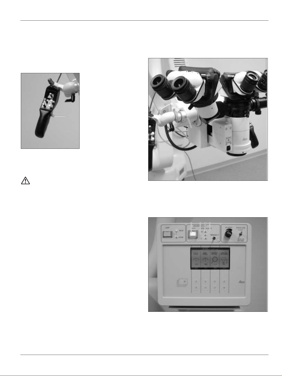
Operating elements
Leica M500 N microscope with
microscope carrier 9
Control unit 10
Footswitches 11
Mouth switch 11
Preparation before surgery
Transportation 12
Preparations before surgery 12
Performing function checks 13
Positioning at operating table 13
After surgery
Tasks to be completed after surgery 13
Operation
Setting/releasing footbrakes 14
Locking the Leica M500 OH3 14
Selecting XYZ-Free/Focus-Lock brakes 15
Balancing out the Leica M500 OH3 15
Switching on illumination 18
Switching from main illuminator to backup
illuminator 18
Setting light field diameter of illumination field and
working distance 19
Lock/release multifocal focus 19
Selecting name of operating doctor at control unit 20
Determining dioptres for users 21
Setting up eyepieces 21
Attaching protective glass to eyepiece 21
Attaching sterile operating elements 22
Operation of control unit 22
Settings at control unit 23
Controlling zoom and focus 28
Pulling in additional cables 29
Changing wheel counterweight at D axis 30
Accessories
180° dual stereo attachment 31
Binocular tube; can be tilted; with variable
viewing angles 30°–150° 31
Stereo/second-observer attachment 31
Beam splitter with counterweight 31
Video-zoom tube 32
Adapter piece for accessories of the
M 600 series 32
Beam splitter 32
Dual Imaging Color Module DI C500 32
Ultra Observer ULT500 32
Mounting accessories 33
2
Page
Safety precautions
Intended use of instrument 34
Directions for the person responsible for the
instrument 34
Directions for the user 34
Dangers of use 35
Labelling 36
Care and maintenance
Care instructions 38
Replacing lamps 38
Replacing fuses 39
Operational check 39
What to do if...?
General faults 40
TV, photography 42
Error messages at control unit 42
Technical data
Electrical data 43
Leica M500 N 43
Accessories 43
Floor stand 44
Standards 44
Environmental conditions 44
Limitations on use 44
Dimensional drawings 45
Page 5
Introduction
Leica M500 OH3 / Ref. 10 711 894 / Version -
User manual
This user manual contains important safety
precautions as well as information on setting up
the instrument (see the chapter entitled «Safety
precautions»).
Before attempting to set up the product carefully
read through the user manual.
Product identification
The model and serial number of your product are located on the
identification label on the illumination unit. Copy this
information into your user manual and always refer to it if you
have questions for our representatives or service locations.
Model: Serial No.:
Symbols used in this manual
The symbols used in this user manual have the following
meaning:
Warning This indicates a potentially hazardous
situation which could result in death or
serious injury.
Caution Indicates a potentially hazardous situation
which, if not avoided, may result in minor
or moderate injury and/or appreciable
material, financial and environmental
damage. It may also be used to alert
against unsafe practices.
Important paragraphs, which must be
adhered to in practice as they enable the
product to be used in a technicallycorrect and efficient manner.
Indicates that you have to do something.
➩
3
Page 6
Introduction
4
Leica M500 OH3 / Ref. 10 711 894 / Version -
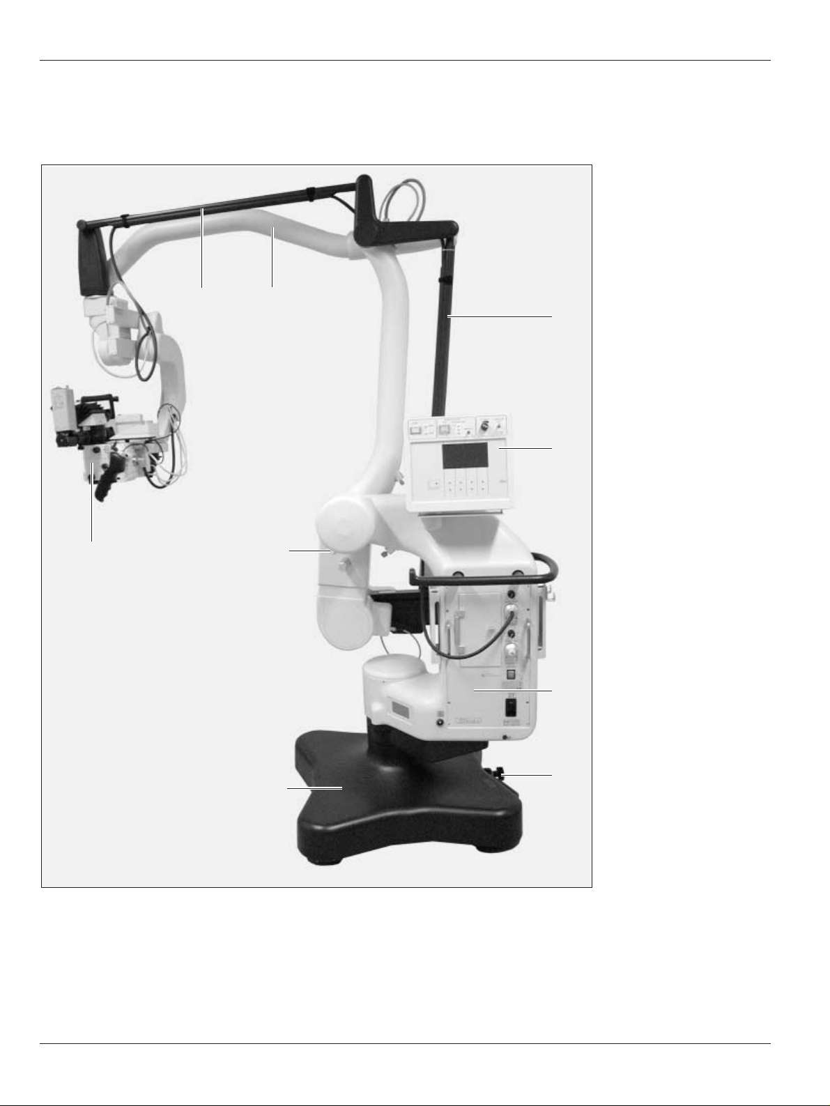
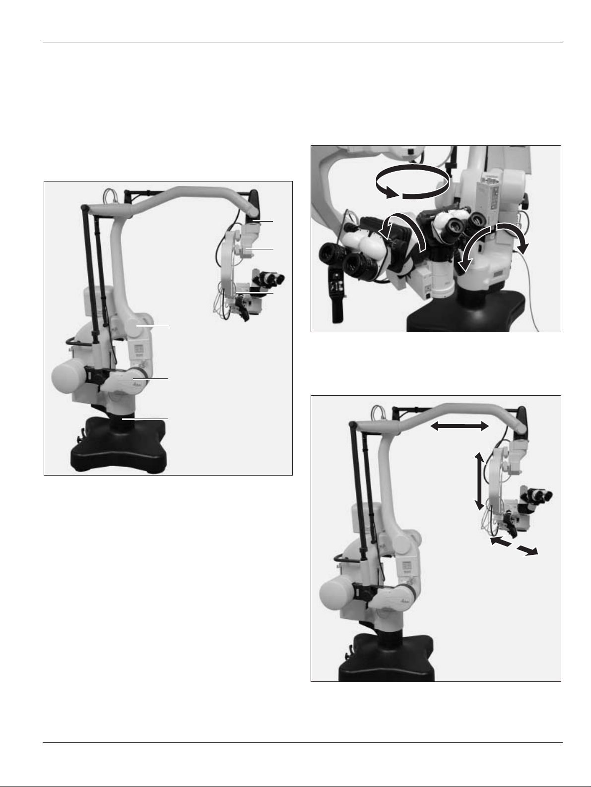
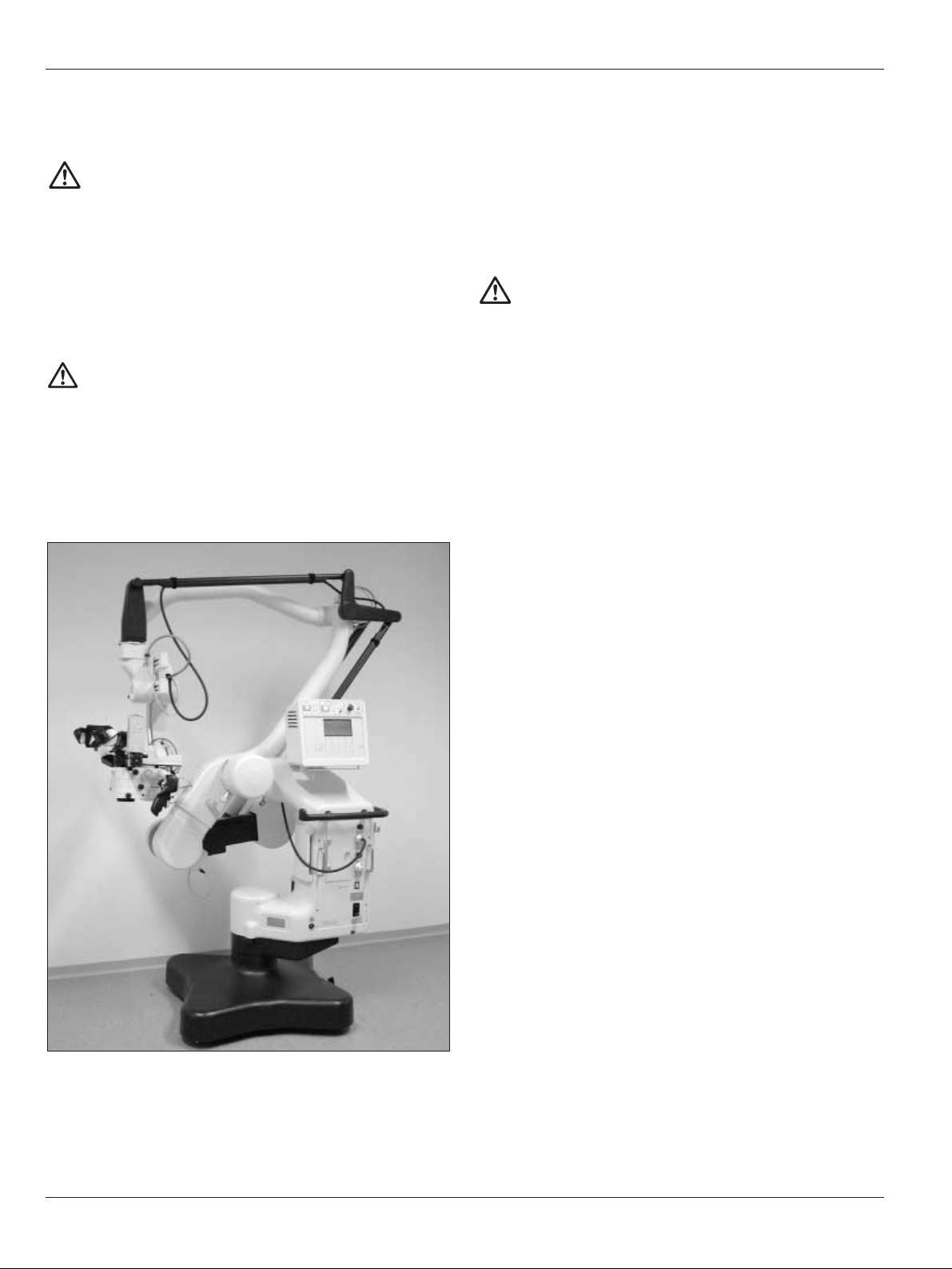
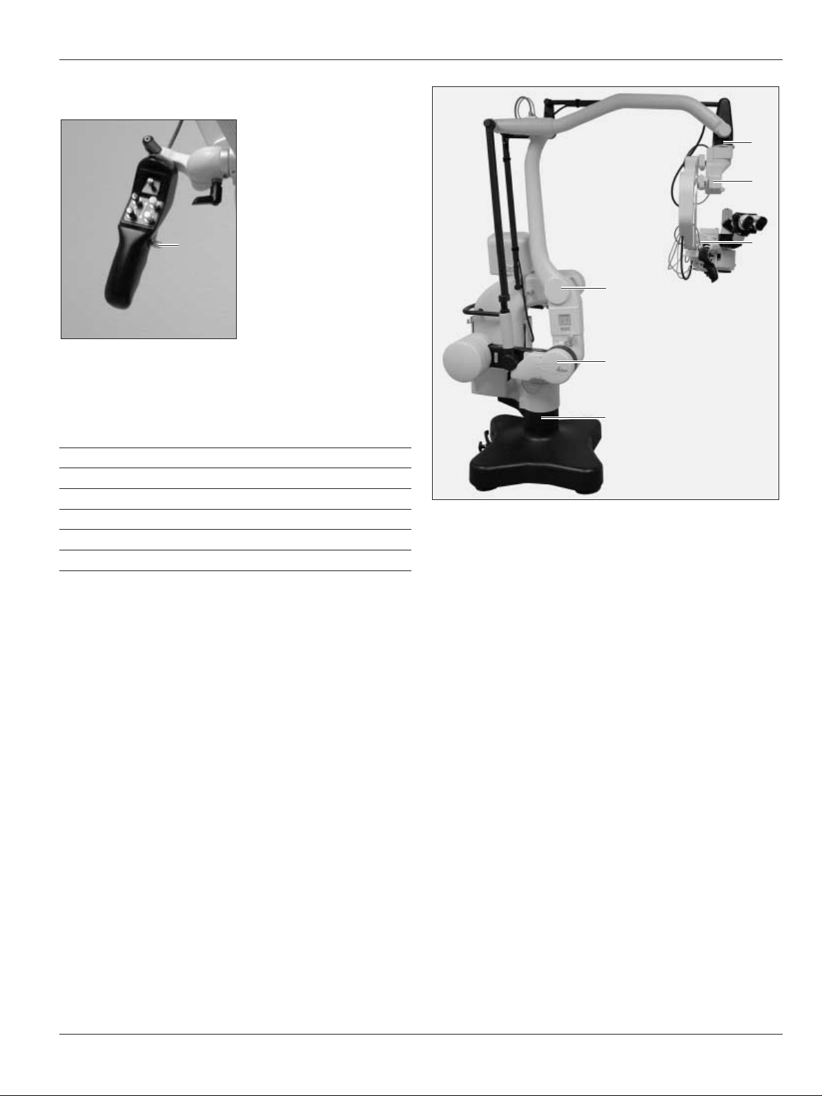
Overview
Leica M500 OH3 surgical microscope system
1 Horizontal cable channel
2 Swing arm
3 Vertical cable channel
4 Control unit
5 Illumination unit
4
5
6
7
9
2
8
3
1
6 Footbrake
7 Foot
8 Locking knob
9 Leica M500 N microscope
Page 7
Introduction
5
Leica M500 OH3 / Ref. 10 711 894 / Version -
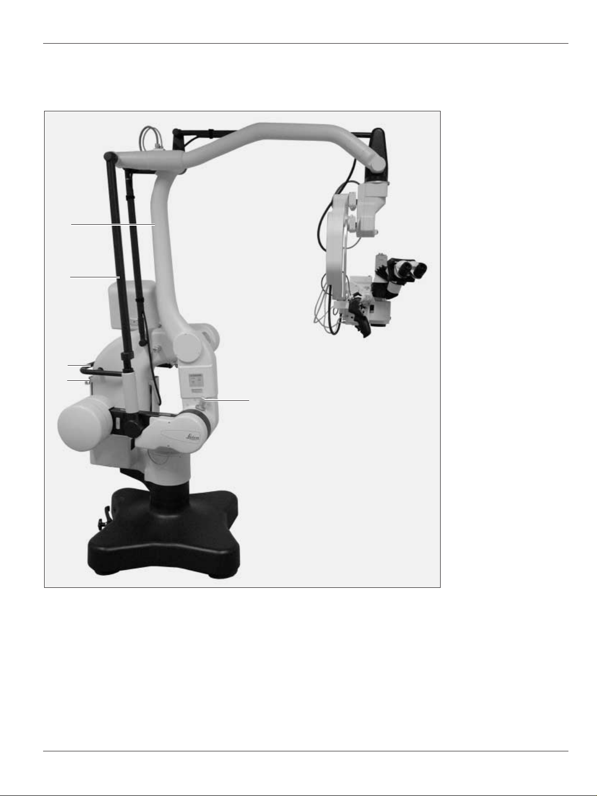
1 Vertical arm
2 Tension rod
3 Handle
4 Footswitch holder
5 Locking knob
1
2
3
4
5
Page 8

Introduction
6
Leica M500 OH3 / Ref. 10 711 894 / Version -
Function
Balancing system and brakes
The Leica M500 OH3 surgical microscope consists of the Leica
M500 N surgical microscope and the Leica OH3 floor stand.
The stand and surgical microscope are balanced out by the
balancing system. All movements which must be carried out
during the surgery require only minimal force.
The AB swivel movement is balanced out via the A and B
pinion.
Movement C is balanced out at the microscope carrier.
C
BA
B
A
The internal weight of the stand balances the weight of the
surgical microscope and the fitted accessories (movement D).
D
D
Page 9
Introduction
7
Leica M500 OH3 / Ref. 10 711 894 / Version -
There are 6 electromagnetic brakes on the Leica M500 OH3
surgical microscope, which block movement of the base and
surgical microscope:
• up/down and forward/backward in a parallelogram (0 and 1)
• at base (2)
• in microscope carrier (3)
• at A and B sledges of the surgical microscope (4)
• in rotatable joint (5)
5
3
4
1
0
2
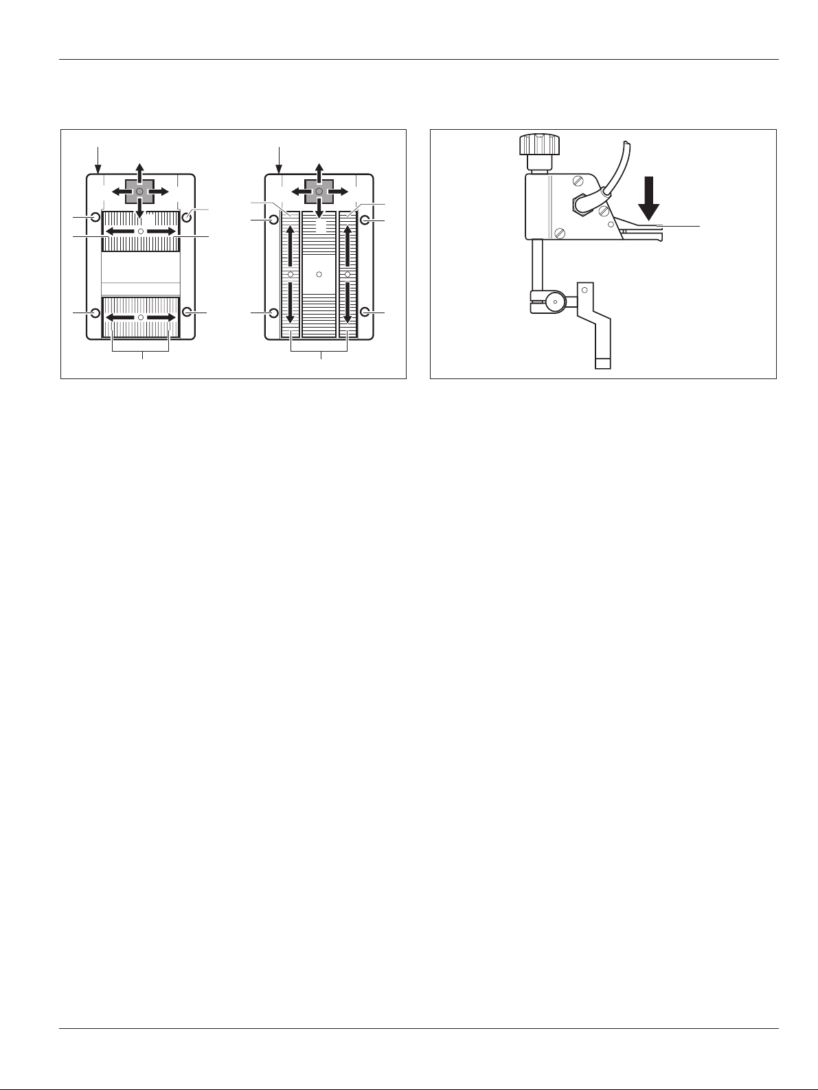
Using the selector switch (Item 10, Page 10) for brakes (XYZ
FREE or FOCUS LOCK) at the control unit, two different brake
groupings can be selected.
The following movements with the surgical microscope can still
be performed if the selector switch is located in the FOCUS
LOCK position:
The following movements with the surgical microscope can be
performed if the selector switch is located in the XYZ FREE
position:
Page 10
Introduction
Leica M500 OH3 / Ref. 10 711 894 / Version -8
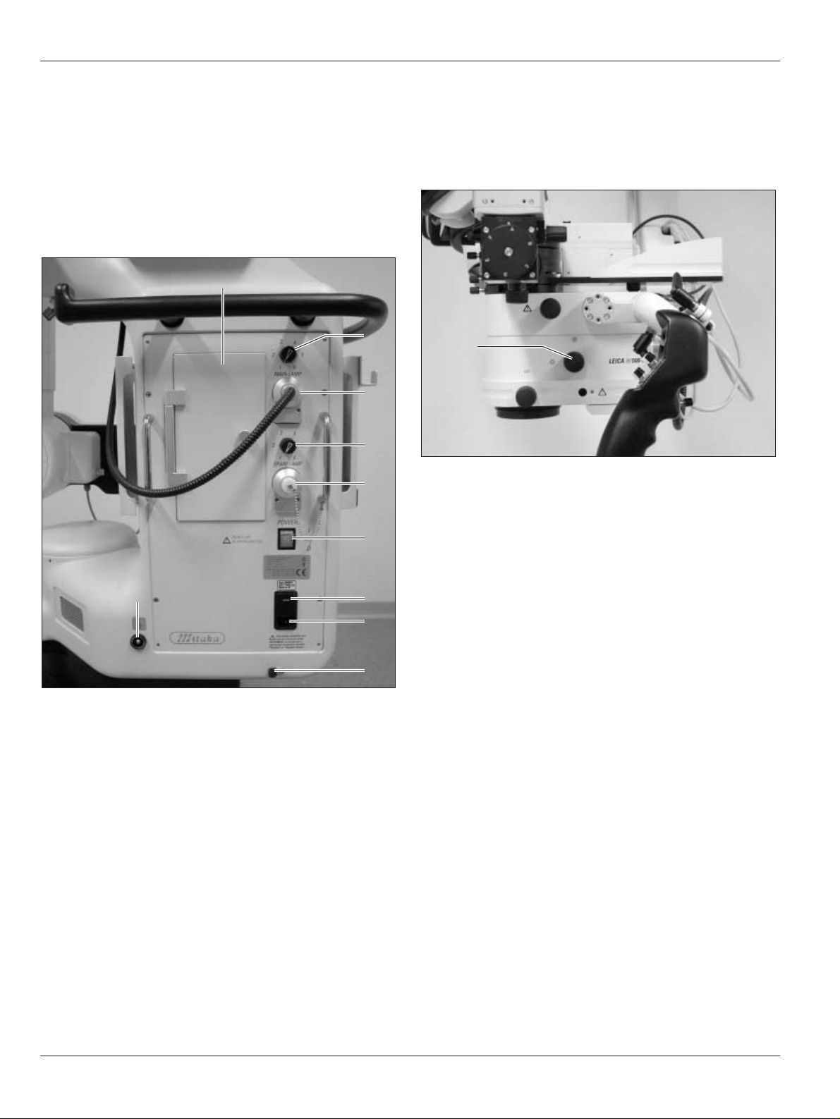
Illumination
The illumination of the Leica M500 OH3 surgical microscope
consists of a main illuminator and a backup illuminator.
They are located in the illumination unit.
The main and backup illuminators consist of xenon lamps. The
light of the main and backup illuminators is lead to the optics
carrier via a fibre-optic cable through the base.
If the main illuminator fails, the plug of the fibre-optic cable is
switched over to the backup illumination.
1 Access hatch for lamp inserts of main and backup
illuminators
2 Regulating knob for brightness of main illuminator
3 Outlet for fibre-optic light guide of main illuminator
4 Regulating knob for brightness of backup illuminator
5 Outlet for fibre-optic light guide of backup illuminator
6 Power switch of Leica M500 OH3 surgical microscope
7 100 V/120 V/220 V/240 V switch
8 Power connection
9 Pullout fuse for power cable
10 Potential equalisation connector
2
1
3
4
5
6
7
8
9
10
Two LEDs at the control unit indicate which illuminator is being
used at the moment (see Page 18).
The light field diameter can be concentrated at the optics
carrier with the rotary knob (11).
11
Page 11
Operating elements
9
Leica M500 OH3 / Ref. 10 711 894 / Version -
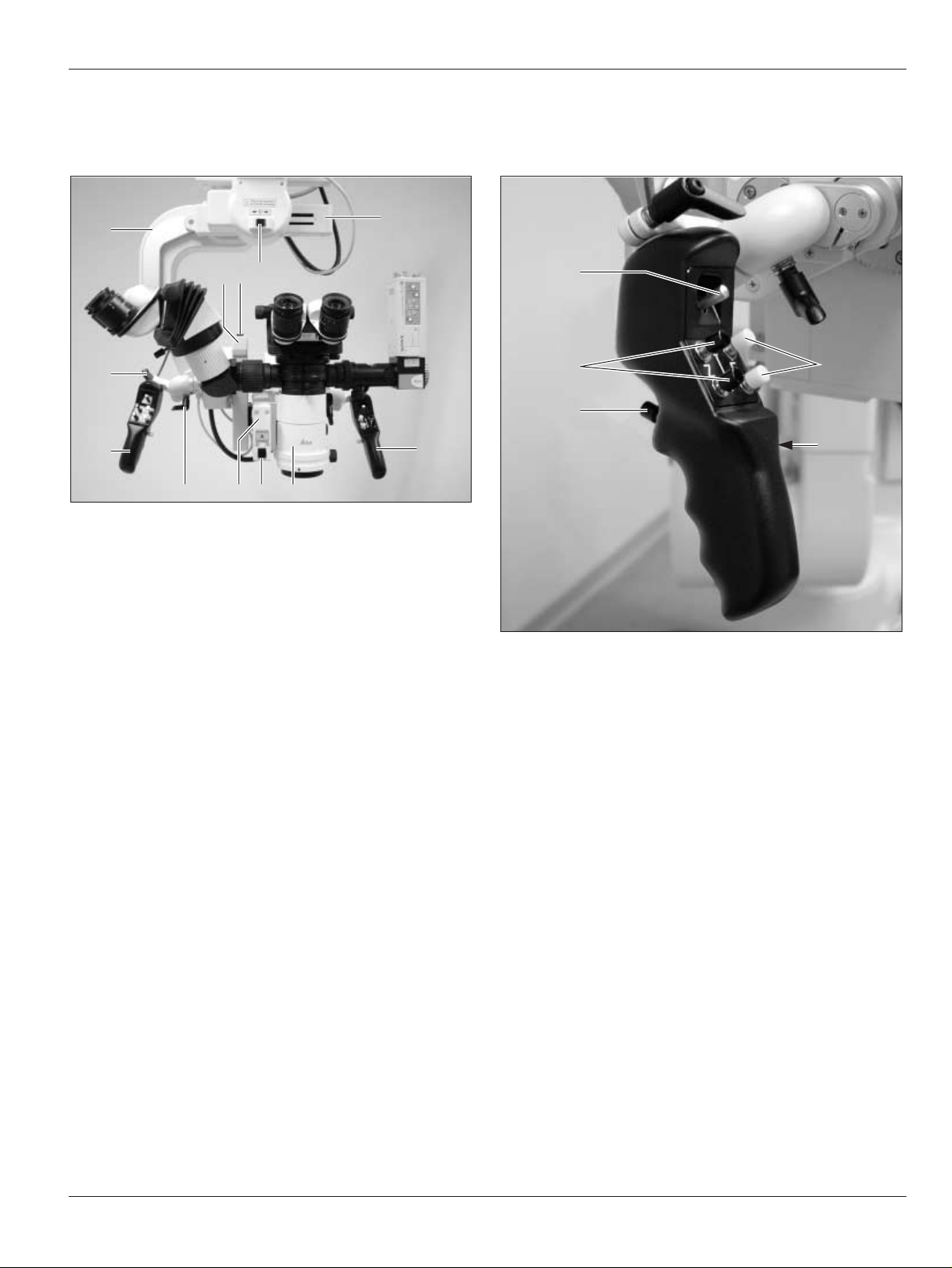
Leica M500 N microscope with
microscope carrier
1 Microscope carrier
2 B sledge
3 Switch for manual balancing of the B sledge
4 Switch for manual balancing of the C sledge
5 C sledge
6 Handgrip
7 Optics carrier
8 Switch for manual balancing of the A sledge
9 A sledge
10 Handgrip clamping lever
1
5
6
789
6
10
23 4
10
Handgrips (Item 6):
11 Joystick (selectable for XY movement or for menu control in
DI C500)
12 Focus
13 Selector button (three brakes)
14 ALL-FREE button (all brakes)
15 Zoom
11
15
14
12
13
Page 12
Operating elements
10
Leica M500 OH3 / Ref. 10 711 894 / Version -
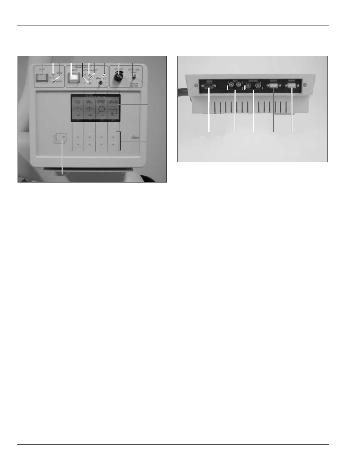
Control unit
1 Pushbutton for illumination (on/off)
2 LED for main illuminator
3 LED for backup illuminator
4 Pushbutton for auto balance with protective flap
5 LED for balancing of D axis
6 LED for balancing of A/B axis
7 LED for balancing of C axis
8 Toggle switch for manual balancing of D axis
9 Regulating knob for movement speed of the X/Y axes
10 Selector switch for brakes:
- XYZ-Free
- Focus-Lock
11 Display
12 Arrow keys
13 Cover for connections
14 Display key for menu control
123 4 5678 9 10
11
12
14
13
Connections on the underside of the control unit (cover for
connections, Item 13 removed):
15 RS-232 interface
16 On/Off connection for external device
17 Footswitches 1 and 2
18 CAN bus interface
19 CAN bus interface
15 16 17 18 19
Page 13
Operating elements
11
Leica M500 OH3 / Ref. 10 711 894 / Version -
Footswitch
1 Adjustable supports
2 DI C500: Activate/deactivate imaging (On/Off)
3 Focus, short working distance
4 DI C500: Individual switching of shutters
DI C500 with IGS workstation: ENTER menu
5 Zoom (freely configurable; for default configuration, see
Page 25)
6 DI C500: Decrease the brightness of the displayed image
DI C500 with IGS workstation: Menu scroll down
7 Focus, long working distance
8 DI C500: Increase the brightness of the displayed image
DI C500 with IGS workstation: Menu scroll up
1
2
3
1
2
5
44 6
8
6
8
Y+
Y-
X+X-
Y+
Y-
X+
X-
7
5
3
7
Mouth switch
9 Brakes XYZ FREE
9
Page 14
Preparation before surgery
12
Leica M500 OH3 / Ref. 10 711 894 / Version -
Transportation
Warning
Risk of injury by:
• Uncontrolled swinging out of swing arm!
• Tilting of the stand!
• Feet in lightweight shoes can become trapped
beneath the base!
➩When transporting the surgical microscope, always
return it to the transport position.
➩Always push the surgical microscope, never pull it.
Caution
Microscope can be damaged by uncontrolled tilting
over!
➩Hold the handgrips firmly before pressing the ALL-
FREE button.
➩Press the ALL-FREE button and bring the Leica M500 OH3 into
the transport position (see figure below).
➩Release footbrakes (see Page 14).
➩Move Leica M500 OH3 via handgrip.
Preparations before surgery
Cleaning optical accessories
➩Inspect the cleanliness of the eyepieces and objective as
well as any photo or TV adapters as appropriate.
➩Remove dust and dirt.
Mounting accessories
Warning
Mortal danger from electrical shock!
➩Connect the Leica M500 OH3 surgical microscope to
an earthed outlet only.
➩Lock the Leica M500 OH3 (see Page 14).
➩Connect power cable.
➩Switch on power switch.
➩Set footbrakes (see page 14).
➩Outfit microscope with all accessories for use.
➩Position hand/mouth switch.
➩Position handgrips as needed for the forthcoming surgery.
➩Screw off cover of connections (Item 13, Page 10), connect
provided footswitch and check settings (see Page 25).
Balancing out microscope
➩Balance out the Leica M500 OH3 (see Page 15).
➩Release locks (see Page 14).
Setting up eyepieces
➩Set eye-base and pupil-base (see Page 19).
➩Set dioptre values for users (see Page 21).
Configuring control unit
➩See the section entitled «Operation of the control unit»,
Page 22.
➩Check settings of the handgrips (DIC function or XY
movement) (see Page 26).
➩Inspect all connections and make certain that all accessories
are seated firmly.
Page 15
Preparation before surgery/After surgery
13
Leica M500 OH3 / Ref. 10 711 894 / Version -
Performing function checks
Illumination
Always allow the main and backup illuminators to
remain lit for at least five minutes, otherwise the
lighting capacity will be quickly reduced.
➩Switch on main illuminator at the illumination unit
(see Page 18).
➩Switch to backup illuminator at the illumination unit
(see Page 18).
➩Switch illumination off again.
Footswitch
➩Test all functions with the footswitch.
Handgrip
➩Press the selection and ALL-FREE buttons and check
movement.
➩Set the movement speed of the X/Y axes with the regulating
knob (Item 9, Page 10) if necessary.
TV camera/monitor and still-photo camera
(if present)
➩Check the image on the TV monitor.
➩Align TV and SLR camera to the microscopic image.
➩For photographs: Insert daylight film.
Sterility
➩Attach sterile components and sterile drapes (see Page 22).
Balancing out microscope
➩Balance out the Leica M500 OH3 (see Page 15).
➩Press the ALL-FREE button and check balancing.
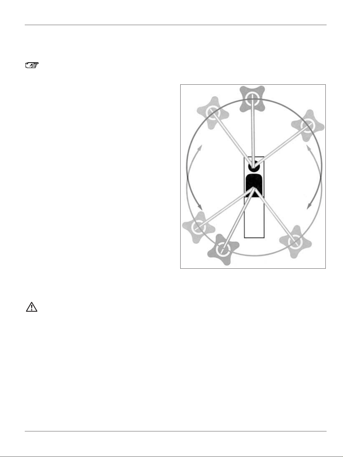
Positioning at operating table
Warning
Risk of injury from tilting surgical microscope!
➩Never change the accessories or attempt to
rebalance the microscope while it is over the field of
operation.
➩Lock the Leica M500 OH3 each time before changing
accessories.
➩Balance out the Leica M500 OH3 each time after
changing accessories.
➩Do not release brakes in an unbalanced state.
Positioning the Leica M500 OH3 at the operating table is quite
easy and offers a multitude of options, whether it be for surgery
at the head, spinal column, etc.
This freedom to choose your position with the M500 OH3 is
thanks to the extra-long and high swing arm.
➩Release footbrakes (see Page 14).
➩Carefully move the Leica M500 OH3 surgical microscope to
the operating table and position it for the forthcoming
surgery.
Positioning possibilities:
➩Set footbrake.
➩Position footswitch.
➩Connect potential equalisation.
Tasks to be completed after surgery
➩Swing microscope away.
➩Move Leica M500 OH3 to the transport position and out of the
operating area.
➩Remove sterile components.
➩Lock the Leica M500 OH3.
➩Move the Leica M500 OH3 to the parked position.
Page 16
Operation
14
Leica M500 OH3 / Ref. 10 711 894 / Version -
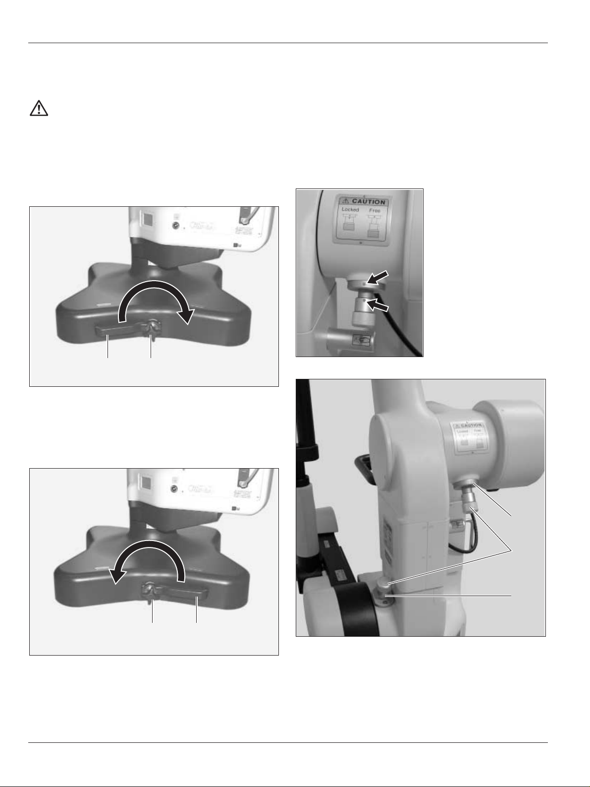
Setting/releasing footbrakes
Warning
Surgical microscope can move without warning!
➩Always set footbrakes, except during transport.
Setting footbrakes
➩Loosen star grip (2).
➩Turn lever for footbrake (1) to the right.
➩Tighten star grip again.
Releasing footbrakes
➩Loosen star grip (2).
➩Turn lever for footbrake (1) to the left.
➩Tighten star grip again.
12
12
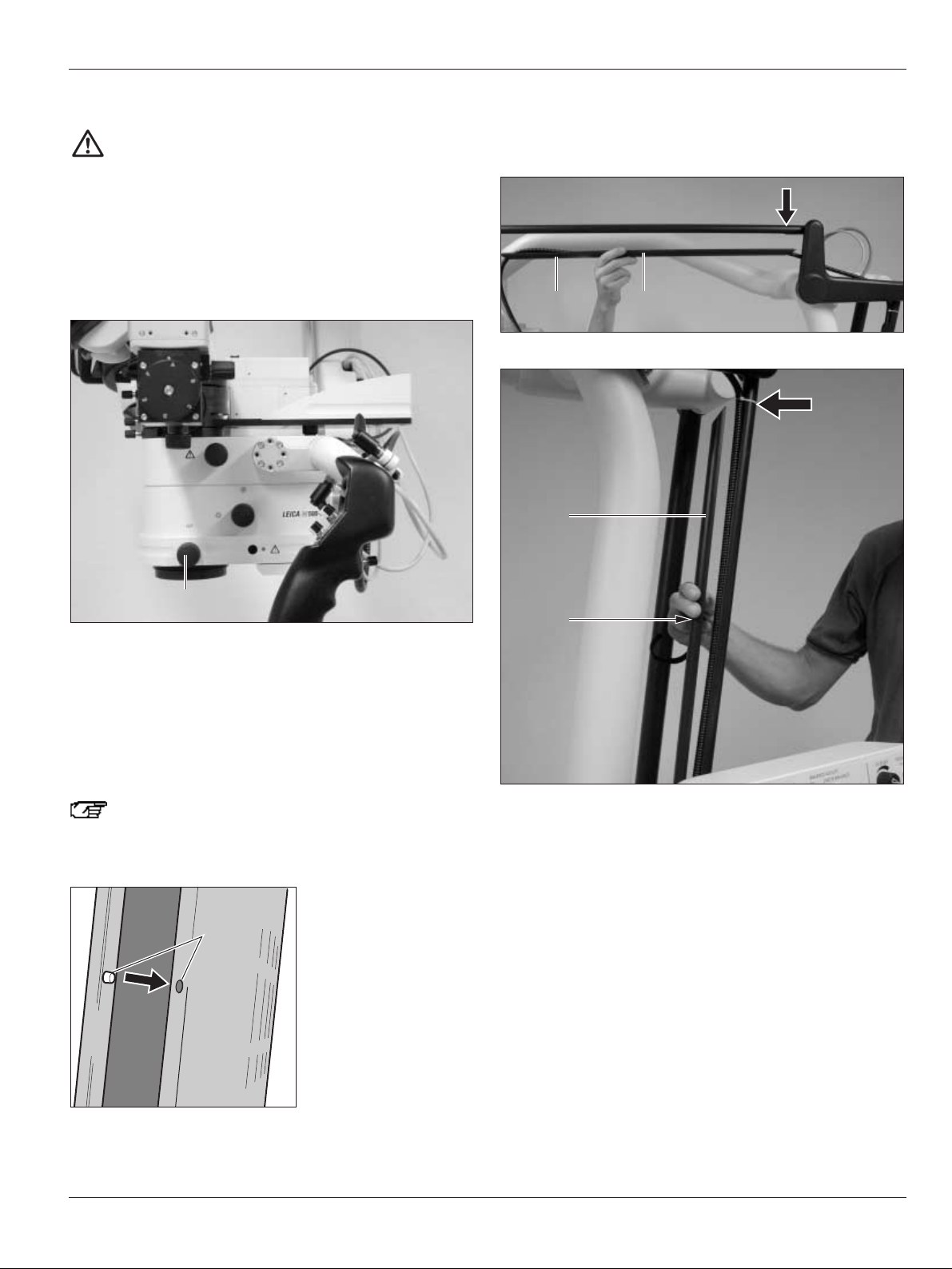
Locking the Leica M500 OH3
The D axis of the Leica M500 OH3 is locked when locking is
performed.
Locking is mainly used for installation and accessory-change at
the Leica M500 OH3.
➩Pull out and turn locking knobs (4) until both points (arrows)
are aligned.
➩Move swing arm up and down until the lock (5) engages.
➩Move swing arm forward and backward until the lock (3)
engages.
4
3
5
Page 17
Operation
15
Leica M500 OH3 / Ref. 10 711 894 / Version -
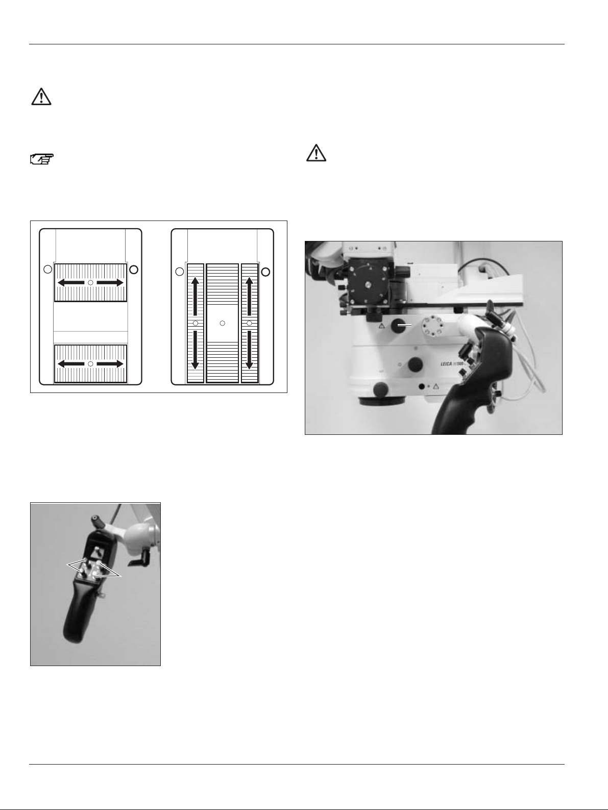
Selecting XYZ-Free/Focus-Lock brakes
➩Pull the selector switch (Item 10, Page 10) and tilt to the
desired brake grouping (XYZ FREE or FOCUS LOCK).
➩Press selector button (1) on handgrip.
The set movements can be made.
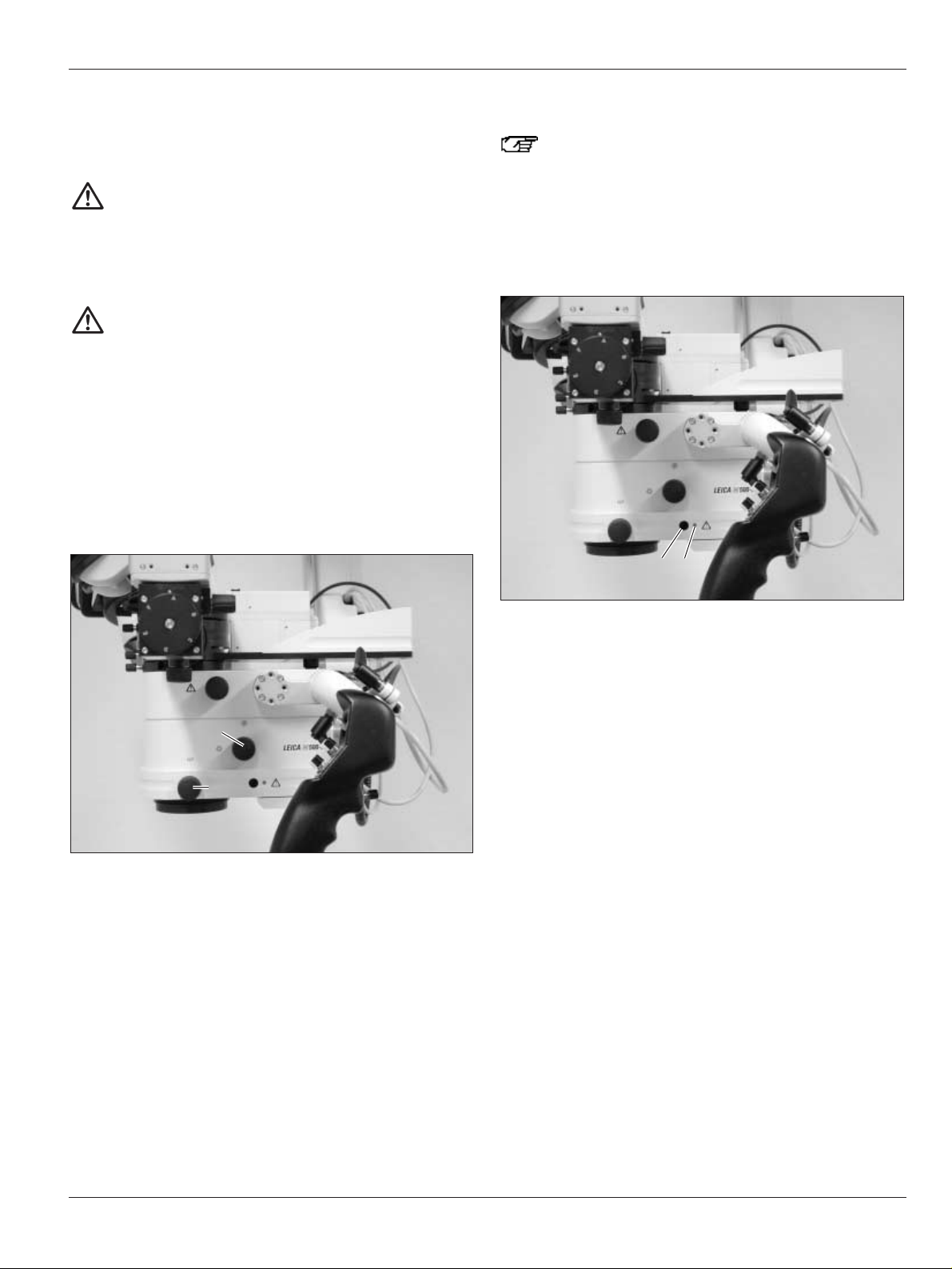
Balancing out the Leica M500 OH3
Warning
Risk of injury by movements of the microscope during
balancing out.
➩Do not remain in the immediate vicinity of the
microscope during balancing out.
➩Switch on the Leica M500 OH3.
➩Mount accessories in the permissible weight range (see
technical data on Page 43).
➩Move the Leica M500 OH3 to the approximate working
position.
➩Press the ALL-FREE button and position the microscope
carrier so that the line (2) points to A.
➩Lift the protective flap and press the pushbutton (3) for auto
balance.
The pushbutton flashes orange and an audible signal is
emitted for the duration of the balancing procedure.
3456
2
1
Page 18

Operation
16
Leica M500 OH3 / Ref. 10 711 894 / Version -
➩When the audible signal stops, press the ALL-FREE button
and swivel the microscope carrier into position B (arrow)
until it engages.
If the mounted accessories (e.g. the tube) do not permit
the 90° swivel movement, turn the tube upward,
perform the swivel movement and then ensure that you
turn the tube back to the working position.
➩Lift the protective flap and press the pushbutton (Item 3, Page
15) again for auto balance.
The pushbutton flashes orange and an audible signal is
emitted for the entire duration of the balancing procedure for
the B, C and D axes.
Balancing is complete when the pushbutton for auto balance
illuminates green and none of the three LEDs (Item 4, 5 or 6,
Page 15) illuminates.
If one of the three LEDs illuminates, balancing must be
checked:
➩Press the ALL-FREE button and check balancing.
Correct balancing manually if necessary.
Correcting balancing manually
Ensure that no accessory parts collide with the
microscope when balancing manually.
As the LEDs (Item 4, 5 and 6, Page 15) also show very
slight balance deviations, the manual balance
correction may only be performed for perceptible
deviations.
➩Press the ALL-FREE button.
The microscope tilts to the side:
➩Press the C (1) button until the microscope is balanced out.
The microscope swivels to the front or back:
➩Press the A (2) button until the microscope is balanced out.
2
1
Page 19

Operation
17
Leica M500 OH3 / Ref. 10 711 894 / Version -
➩Press the ALL-FREE button and swivel the microscope carrier
into position B until it engages.
If the mounted accessories (e.g. the tube) do not permit
the 90° swivel movement, turn the tube upward,
perform the swivel movement and then ensure that you
turn the tube back to the working position.
➩Press the B (1) button until the microscope is balanced out.
The microscope moves upward:
➩Press the selector switch (2) to the left (–) until the
microscope is balanced out.
2
1
The microscope moves downward:
➩Press the selector switch (2) to the right (+) until the
microscope is balanced out.
If the microscope cannot be balanced manually, the
accessories are probably not in the balanceable
weight range.
This can be solved for the A/B/C axes by
decreasing/increasing the accessory weight in the
acceptable range (8 kg–11.7 kg of accessories).
The D axis can be adapted by the number of wheel
counterweights (see Page 30).
2
Page 20

Operation
18
Leica M500 OH3 / Ref. 10 711 894 / Version -
Switching on illumination
Always allow the main and backup illuminators to
remain lit for at least five minutes, otherwise the
lighting capacity will be quickly reduced.
➩Press pushbutton (1) for illumination.
The illumination is activated, the pushbutton illuminates
green and the LED (2) for the main illuminator or the LED (3)
for the backup illuminator illuminates.
Switching from main illuminator to
backup illuminator
➩Unplug the fibre-optic light guide at connector (4) of the main
illuminator.
The pushbutton (6) for illumination flashes orange and the
LED (7) for the main illuminator goes out.
4
5
1 23
➩Insert the fibre-optic light guide into the connector (5) of the
backup illuminator and press the pushbutton (6) for
illumination.
The pushbutton for illumination illuminates green and the LED
for the backup illuminator (8) illuminates orange.
Replace defective illumination at the next opportunity
and reinsert the fibre-optic light guide into the
connector of the main illuminator again.
678
Page 21
Operation
19
Leica M500 OH3 / Ref. 10 711 894 / Version -
Setting light field diameter of
illumination field and working distance
Warning
Severe damage to tissue can result from an incorrect
working distance!
➩When working with lasers, always set the working
distance of the microscope to the laser distance and
lock it there.
Warning
Severe injury to tissue can result from manual
adjustment of the working distance!
➩The rotary knob may not be adjusted for manual
adjustment of the working distance while the laser is
in use.
➩Set the required working distance with the focus buttons on
the handgrip/footswitch or, if a fault occurs, manually with
the rotary knob (2).
➩Set the desired light field diameter/brightness with the rotary
knob (1).
1
2
Lock/release multifocal focus
Locking the focus is necessary when using a fixed
working distance or when working with a laser.
➩Press button (3).
The yellow LED (4) illuminates and the focus is locked.
➩Press button (3) again.
The yellow LED (4) goes out and the focus is released.
3 4
Page 22

Operation
20
Leica M500 OH3 / Ref. 10 711 894 / Version -
Selecting name of operating doctor at
control unit
➩Call up main menu 1 at the control unit with the display key.
➩Select the entry «Change user» in main menu 1 with the
arrow keys «up/down» and confirm with «ok».
➩Select the name of the operating doctor with the arrow keys
«up/down» and confirm with «ok».
The dioptre values, eye-base and eyepiece magnification of the
selected doctor are shown in the display.
Dr. Keller
ok
IPD: 65
Diop. L: + 0.0
Diop. R: + 0.0
Eyepiece magnification: 10
Select user
up/down ok cancel
DR. KELLER
DR. SMITH
DR. LEGRAND
DR. DEHMER
DR. GRAZZINI
DR. JONES
DR. DUPONT
DR. WATTS
➩Set values at the eyepiece/tube.
➩Confirm with «ok» (for information on changing settings, see
the chapter entitled «Changing eye-base, dioptre values and
eyepiece magnification», Page 24).
The values for focus and zoom speed, magnification and
working distance of the selected doctor are shown in the
display.
➩For changing the displayed values, see «Setting focus and
zoom speed, magnification and working distance», Page 24.
Dr. Keller
+/– +/– +/– +/–
FOCUS
SPEED
ZOOM
SPEED
MAGNIFI
CATION
WORKING
DISTANCE
48 % 50 %
3.0 300
Page 23
Operation
21
Leica M500 OH3 / Ref. 10 711 894 / Version -
Determining dioptres for users
The individual dioptres can be regulated continuously from +5
to –5.
The treatment microscope ensures a high degree of fatigue
resistance when the dioptre setting is correct for both eyes.
Preparations
➩Open any double-iris diaphragm used.
➩Turn both eyepieces to <0>.
Sharpening test object image:
➩Select magnification 13.7.
➩Place a flat test object with sharp contours under the
eyepiece at the working distance.
➩Move the microscope toward the test object via the camera
or graticule until it appears sharp.
Setting dioptre
➩Select the lowest magnification (magnification 6.4).
➩Without looking into the eyepieces, turn both eye lenses
to +5.
➩Slowly turn the eyelenses toward –5 individually for each eye
until the test object appears sharp.
Checking the setting
➩Select the greatest magnification (magnification 13.7).
➩Check sharpness and adjust if necessary.
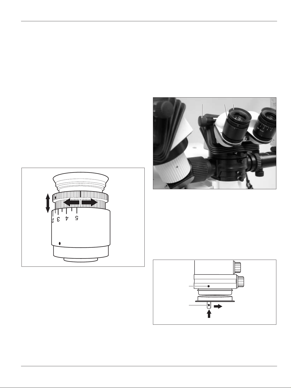
Setting up eyepieces
Setting dioptre values for users
The dioptrics are to be set exactly separately for both eyes;
only then does the sharpness remain constant within the entire
zoom range = parfocal.
➩Read dioptre values of the operating doctor at the control unit
(see Page 20).
➩Set dioptre values at each eyepiece individually with the
setting ring (2).
Setting eye-base and pupil-base
➩Set eye-base with setting wheel (3).
➩Set pupil-base with rotating ring (1).
Attaching protective glass to eyepiece
➩Place the protective glass, which can be sterilised with gas,
on the eyepiece so that the markings on the optics carrier (4)
and on the protective glass (5) are aligned.
➩Lead protective glass into the bayonet lock upward in
direction (a).
➩Turn protective glass in direction (b) until it engages.
a
b
4
5
1 23
Page 24

Operation
22
Leica M500 OH3 / Ref. 10 711 894 / Version -
Attaching sterile operating elements
Rotary knobs of the Leica M500 OH3 surgical microscope can
be provided with covers which can be sterilised.
Covers for rotary knobs
Also attach the covers if you are using sterile
disposable covers.
The operating elements are then easier to grip.
➩Slide covers, which can be sterilised with steam, over the
adjusting knob for the light field diameter and the adjusting
knob for the working distance.
➩Attach covers, which can be sterilised with steam, to
accessories as well (if present).
Cover for footswitch
Caution
Risk of infection!
➩Provide sufficient open space around the base to
prevent the sterile cover being touched by non-sterile
parts.
Packing the footswitch in a plastic bag protects it
being soiled.
Sterile cover for base
➩Switch on main illuminator.
➩Press ALL-FREE button on handgrip and stretch out swing
arm.
➩Wear sterile gloves.
➩Attach all sterile operating elements.
➩Carefully unpack sterile cover and pull it over the microscope
and swing arm.
➩Secure protective glass at eyepiece.
➩Do not fasten sterile cover with accompanying bands too
tightly. It must still be possible to move the instrument easily.
Check for easy ability to be moved.
Operation of control unit
Functions of control unit
• Save individual settings of the operating doctor
• Save current settings
• Set all motor functions continuously
• Display error messages
Calling up main menus
➩Actuate main switch at basic tower.
The control unit is activated.
Zoom and multifocal are initialised.
➩Call up the three main menus with the display key (Item 14,
Page 10).
Functions in main menu 1
• Call up name of the operating doctor (see Page 20)
• Change eye-base, dioptre values and eyepiece magnification
(see Page 24)
• Clear displayed error messages (see Page 24)
Functions in main menu 2
• Change standard setting (see Page 24)
• Initialise microscope (required if contact with the microscope
was interrupted)
• Call up service menu
Settings in the service menu may only be made by
service technicians.
Standard setting
Menue I
Change user
IPD/Diopter L/Diopter R
Clear error messages
up/down ok cancel
Standard setting
Menue II
User settings
Initialize microscope
Service Menue
up/down ok cancel
Page 25
Operation
23
Leica M500 OH3 / Ref. 10 711 894 / Version -
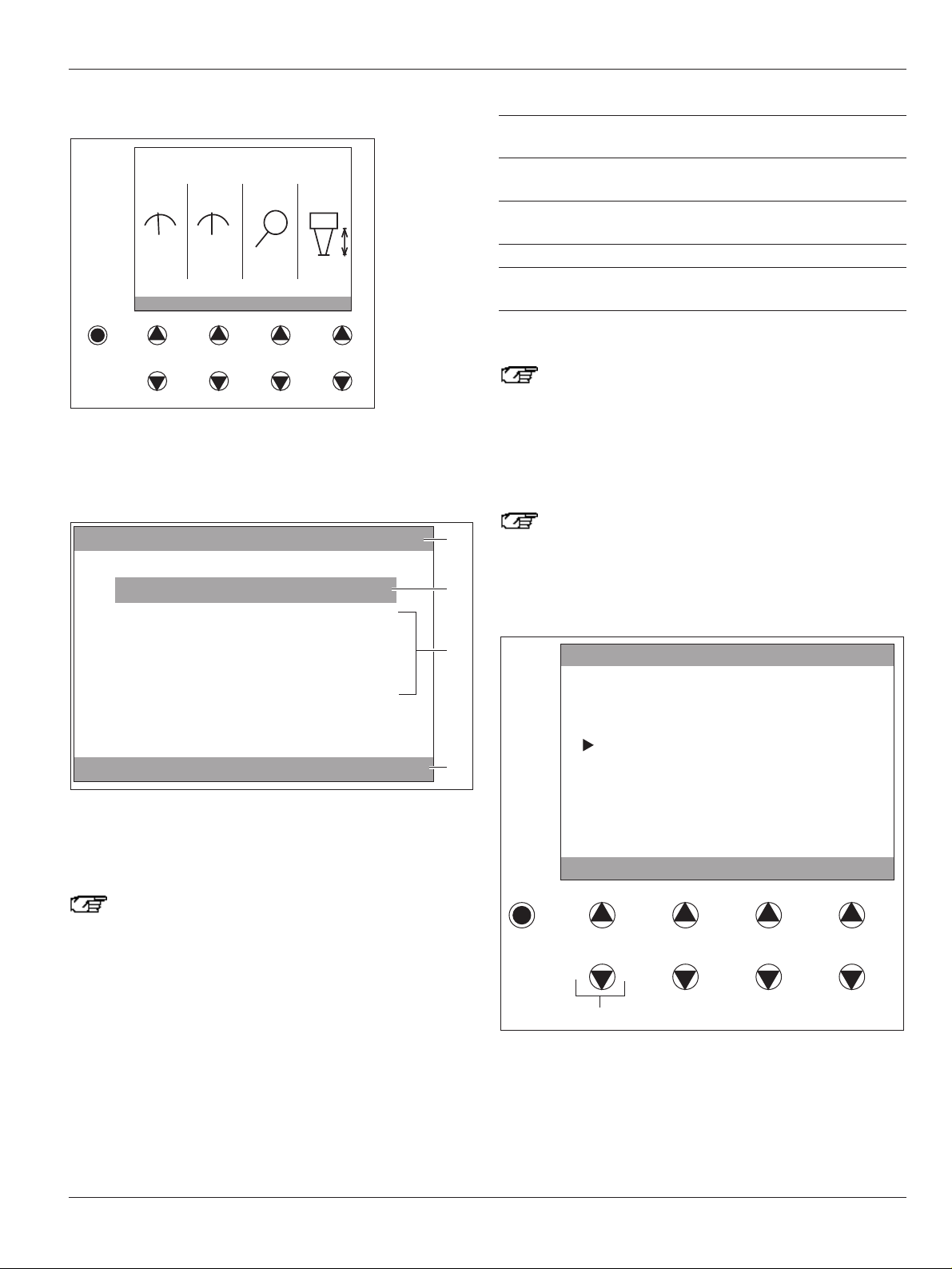
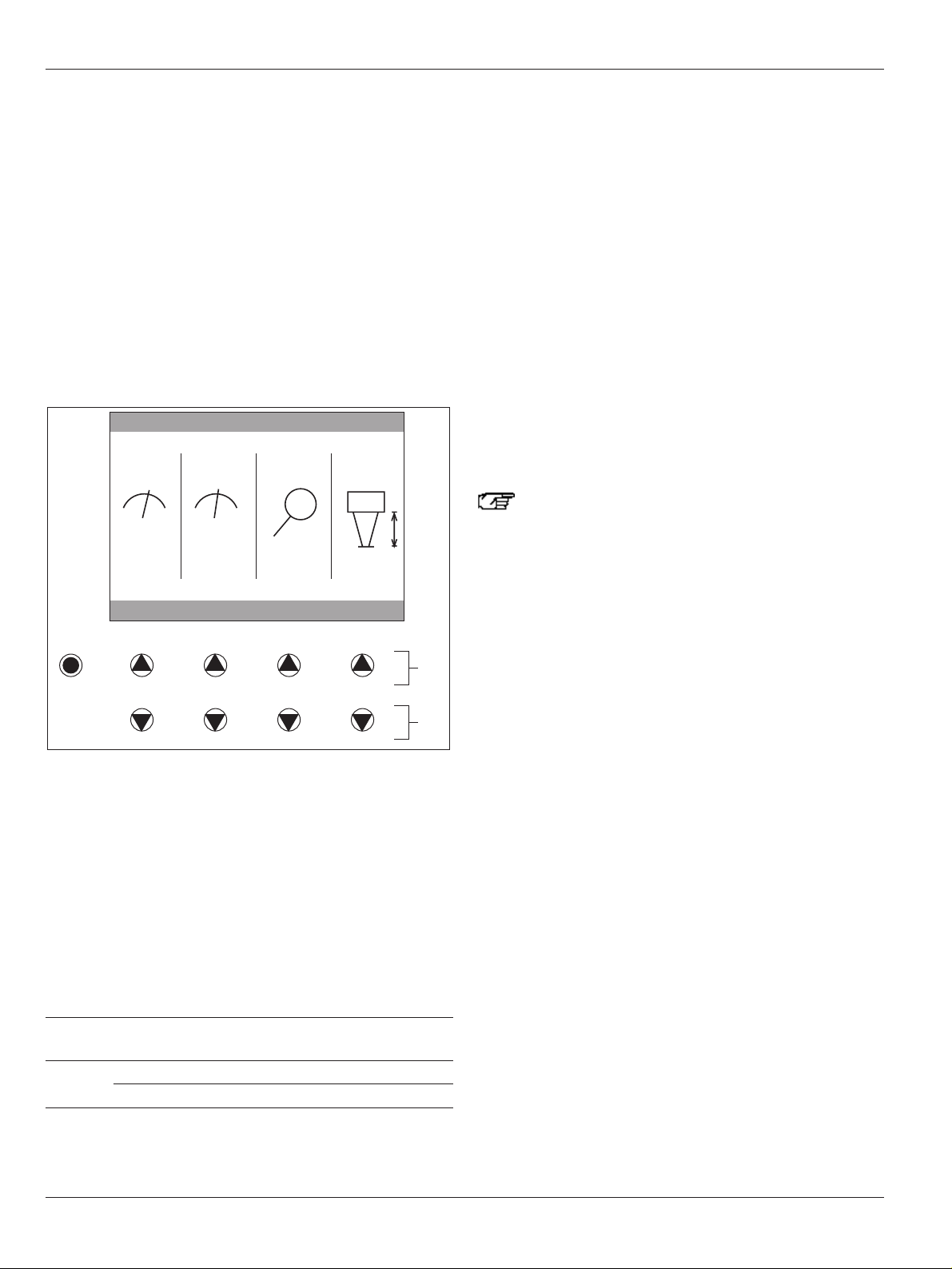
Functions in main menu 3
• Set focus and zoom speed, magnification and working
distance (see Page 24)
Main menu interface
1 Title line
2 Status line
3 User area
4 Activity line
The control unit is always in the «standard setting»
mode after switch-on. In this mode, the displayed
values can only be checked, not changed. For information on changing standard settings, see Page 24.
The title line (1) of the display shows the name of the doctor
whose settings were selected or «standard setting».
The status line (2) indicates the settings which are currently
being edited at the control unit or the main menu which is
currently active.
The user area (3) shows the selection options from which the
user can choose. Exception: error messages and other
information.
The activity line (4) shows the effect of the arrow keys located
below.
Activity line Effect
up/down The pointer in the user area moves up or
down when the arrow keys are pressed.
+/– The selected value increases or
decreases.
ok The selection at which the pointer is
currently located is called up.
save, ok/save The entered value is saved.
cancel Return to the previous menu field without
saving.
Reactivating background lighting
If nothing is entered at the control device for one
minute, the display switches to low-power mode and
the background lighting goes out.
➩Press one of the arrow keys or the display key.
Settings at control unit
If a DI C500 module is used, please observe the user
settings for the DI C500 at the control unit in the Leica
DI C500/Leica ULT500 user manual/installation
instructions.
Calling up name of operating doctor
➩Call up main menu 1 with the display key.
➩Select «Change user» in main menu 1 with the arrow keys (5)
and confirm with «ok».
Select user
up/down ok cancel
Standard setting
DR. KELLER
DR. SMITH
DR. LEGRAND
DR. DEHMER
DR. GRAZZINI
DR. JONES
DR. DUPONT
DR. WATTS
5
Standard setting
FOCUS
SPEED
48 % 50 %
ZOOM
SPEED
+/– +/– +/– +/–
MAGNIFI
CATION
3.0 300
WORKING
DISTANCE
Dr. Keller
Menue I
Change User
Save actual settings
IPD/Diopter L/Diopter R
Clear error messages
1
2
3
up/down ok cancel
4
Page 26
Operation
24
Leica M500 OH3 / Ref. 10 711 894 / Version -
➩Select the name of the operating doctor with the arrow keys
and confirm with «ok».
The dioptre values, eye-base and eyepiece magnification of
the selected doctor are shown in the display.
➩Check all values and confirm with «ok» (for information on
changing settings, see «Changing eye-base, dioptre values
and eyepiece magnification», Page 24).
The values for focus and zoom speed, magnification and
working distance of the selected doctor are shown in the
display.
The displayed values can be changed with the arrow keys and
saved as well.
Setting focus and zoom speed, magnification and working
distance
The following information is relative to a 10x eyepiece.
➩Press the ▲▲ buttons (1).
The values for focus speed, zoom speed and magnification
are increased and the value of the working distance
increases.
➩Press the ▼ buttons (2).
The values for focus speed, zoom speed and magnification
are decreased and the value of the working distance
decreases.
Setting ranges and measurement information
Speed Magnification Working
Focus Zoom distance
Measurement % % factor mm
information
Limits 0 0 1.4 407
100 100 13.7 207
Dr. Keller
+/– +/– +/– +/–
FOCUS
SPEED
ZOOM
SPEED
MAGNIFI
CATION
WORKING
DISTANCE
62% 55%
03.5 269
1
2
Changing eye-base, dioptre values and eyepiece magnification
➩Select «Eye-base and dioptre data» in main menu 1 with the
arrow keys and confirm with «ok».
➩Change the eye-base, left and right dioptre value and
eyepiece magnification of the selected doctor with «+/-».
➩When all values are entered, confirm with «Save».
Switching to settings of another doctor
➩Select «Change user» in main menu 1 with the arrow keys
and confirm with «ok».
A list of names appears for doctors who have saved settings
at the microscope.
➩Select the name of the doctor under «Select user» and
confirm with «ok».
The settings of the selected doctor are active.
Changing standard setting
The Leica M500 OH3 surgical microscope is supplied from the
factory with the standard setting, which can be changed as
desired.
If you have changed the standard setting and would
like to restore the factory setting, you can load it from
the service menu. Only a service technician can make
this setting.
➩Select «Change user» in main menu 1 with the arrow keys
and confirm with «ok».
➩Select «Standard setting» under «Select user» and confirm
with «ok».
The standard settings can now be changed.
Clearing error messages
If a fault occurs in the Leica M500 OH3, an error message
appears on the display.
➩Eliminate fault (see the chapter entitled «What to do if...»,
Page 40).
➩Go to «Clear error messages» in main menu 1 and confirm
with «ok».
The error message is cleared from the display.
Selecting footswitch type
Four different footswitches are available.
➩Go to «User settings» in main menu 2 and confirm with «ok».
➩Determine which connector (1 or 2) at the control unit is used
to connect the footswitch.
➩Select «Foot/handswitch connector 1» or «Foot/handswitch
connector 2» under «User settings» and confirm with «ok».
➩Select «Set foot/handswitch type» under «Function» and
confirm with «ok».
➩Select the desired type under «Foot/handswitch type» and
confirm with «Save».
Page 27
Operation
25
Leica M500 OH3 / Ref. 10 711 894 / Version -
Changing settings for footswitch 1/2
Always pay attention to the title line. It displays the
name of the doctor who just saved the settings which
were called up. This is to prevent the settings of other
doctors from being changed or deleted.
➩Go to «Change user» in main menu 1 and confirm with «ok».
A list of names appears for doctors who have saved settings
at the microscope.
➩Select the name of the doctor under «Select user» and
confirm with «ok».
The settings of the selected doctor are active and the eyebase, dioptre numbers and eyepiece magnification entered
by the doctor appear in the display.
➩Continue with «ok».
➩Select «User settings» in main menu 2 and confirm with «ok».
➩Select «Foot/handswitch connector 1» or «Foot/handswitch
connector 2» under «User settings» and confirm with «ok».
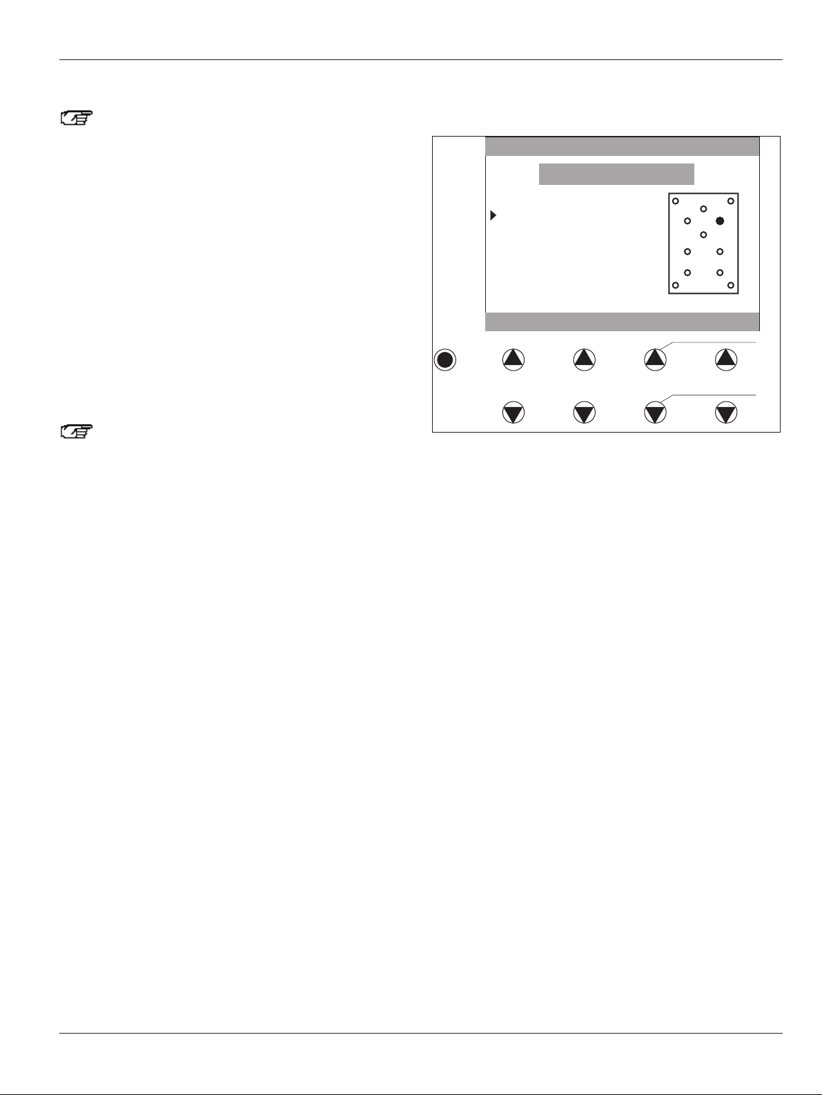
User configuration:
There are two footswitch configuration variants:
«Standard configuration» and «User configuration».
With the «standard configuration», certain
configurations of the keys and pedals are suggested
and can be saved. With the «User configuration»
variant, the pedals can be configured as desired.
➩Select «User configuration footswitch» under «Function» and
confirm with «ok».
➩Select the desired pedal (❍ becomes ●) under «Select
switch» with the right arrow keys under «up/down» in the
sketch in the display.
➩Select the desired function with the left arrow key under
«up/down» (e.g. «focus up»).
➩Confirm with «ok», i.e. upper arrow key (1), and select the
next pedal.
➩When all functions have been selected and confirmed with
«ok», save the setting with «Save», i.e. lower arrow key (2).
The configuration is now saved for the selected doctor.
From a user configuration back to the standard configuration:
➩Select the «Standard configuration foot/handswitch» under
«Function» and confirm with «ok».
➩Accept the recommended configuration with «Save».
The standard configuration of the selected function is
displayed in the sketch (❍ becomes ●).
Performing function check on footswitch
A function test can be performed to check the configuration of
the footswitch.
➩Select «User settings» in main menu 2 and confirm with «ok».
➩Select «Foot/handswitch connector 1» or «Foot/handswitch
connector 2» under «User settings».
➩Select «Control foot/handswitch functions» under «Function»
and confirm with «ok».
➩Press any button on the footswitch.
The set function with an arrow symbol is displayed to the left
and the ❍ symbol in the symbol picture on the right changes to
●.
Dr. Keller
Select switch using
up/down cancel ok/save up/down
Working distance long
Working distance short
Zoom up
Zoom down
Additional function 1
Additional function 2
X+
XY+
YNot used
1
2
Page 28

Operation
26
Leica M500 OH3 / Ref. 10 711 894 / Version -
Setting focus and zoom speed, focus and zoom position and
eyepiece magnification
Always pay attention to the title line. It displays the
name of the doctor who just saved the settings which
were called up. This is to prevent the settings of other
doctors from being changed or deleted.
➩Select «User settings» in main menu 2 and confirm with «ok».
➩Select «Microscope» under «User settings» and confirm with
«ok».
➩Select either «Focus speed and position», «Zoom speed and
position» or «Eyepiece magnification» under «Function» and
confirm with «ok».
➩Set the desired value with «+/–» and accept with «Save».
Changing contrast and brightness of control device display
➩Go to «Change user» in main menu 1 and confirm with «ok».
A list of names appears for doctors who have saved settings
at the microscope.
➩Select the name of the doctor under «Select user» and
confirm with «ok».
The settings of the selected doctor are active and the dioptre
values, eye-base and eyepiece magnification of the selected
doctor are shown in the display.
➩Continue with «ok».
➩Select «User settings» in main menu 2 and confirm with «ok».
➩Select «Control unit» under «User settings» and confirm with
«ok».
➩Select «Screen contrast/illumination» under «Function» and
confirm with «ok».
➩Select «Screen contrast» or «Background illumination» with
the arrow keys, set the desired value with «+/–» and confirm
with «Save».
Entering or changing user name
➩Go to «Change user» in main menu 1 and confirm with «ok».
A list of names appears for doctors who have saved settings
at the microscope.
➩Select the name of the doctor under «Select user» and
confirm with «ok».
The settings of the selected doctor are active and the dioptre
values, eye-base and eyepiece magnification of the selected
doctor are shown in the display.
➩Continue with «ok».
➩Select «User settings» in main menu 2 and confirm with «ok».
➩Select «Control unit» under «User settings» and confirm with
«ok».
➩Select «User name» under «Functions» and confirm with
«ok».
➩Place the flashing cursor under the desired code with <–/–>.
➩Select the code to be set in the code table with «Code +/–»
(code has black background) and set it with «Set/ins».
The code is inserted into the line and the cursor jumps to the
next free position.
➩Search for and insert next code.
If the user name is entered:
➩Select «Done/del».
«Save, continue or cancel» appears on the status line.
➩Select the desired function with the arrow keys.
Changing settings for handgrips (joystick and brakes)
The joystick (1) can be configured for the XY movement of the
microscope or for menu control when using a DI C500.
Setting configuration of joystick:
➩Go to «User settings» in main menu 2 and confirm with «ok».
➩Select «Left handgrip» or «Right handgrip» under «User
settings» and confirm with «ok».
➩Select «X/Y» or «DIC» under «Right handgrip» / «Left
handgrip» and confirm with «Save».
1
Page 29
Operation
27
Leica M500 OH3 / Ref. 10 711 894 / Version -
Setting brake combination:
Three of the six brakes of the Leica M500 OH3 surgical
microscope can be released in combination at the selector
button (1).
Brake No. Position
0 Up/down in parallelogram
1 Forward/backward in parallelogram
2 At base
3 In C sledge of microscope carrier
4 At A/B sledges of the surgical microscope
5 In rotatable joint
• Brake Nos. 0, 1 and 2 for moving the stand (XYZ FREE)
• Brake Nos. 3, 4 and 5 for moving the Leica M500 N (FOCUS
LOCK) surgical microscope
1
5
3
4
1
0
2
Page 30
Operation
28
Leica M500 OH3 / Ref. 10 711 894 / Version -
Controlling zoom and focus
Warning
Severe damage to tissue can result from an incorrect
working distance!
➩When working with lasers, always set the working
distance of the microscope to the laser distance.
If the zoom or focus motor fails, the zoom or focus can
be set manually.
With footswitch
➩Control zoom and focus by pressing on the pedals.
The pedals are moved crosswise or lengthwise.
The configuration of the buttons and pedals can be selected
individually (see the section entitled «Changing settings for
footswitch 1/2», Page 25).
With handgrips
Zoom (1)
– Upper button: magnify
– Lower button: reduce
Focus (2)
– Upper button:
increase working distance
– Lower button:
decrease working distance
2
1
Setting zoom and focus speed
The zoom and focus speed is set at the control unit (see the
section entitled «Setting focus and zoom speed, magnification
and working distance», Page 24).
Setting zoom manually
Caution
Zoom motor can be permanently damaged!
➩Only adjust the zoom manually if the zoom motor is
defective.
If the zoom motor fails, zooming can be set manually with the
rotary knob (3).
➩Press rotary knob (3).
➩Set desired zoom by rotating it.
3
Page 31
Operation
29
Leica M500 OH3 / Ref. 10 711 894 / Version -
Adjusting focus manually
Warning
Severe injury to tissue can result from manual
adjustment of the working distance!
➩The rotary knob may not be adjusted for manual
adjustment of the working distance while the laser is
in use.
If the focus motor fails, focusing can be set manually with the
rotary knob (1).
➩Set the required focus with the rotary knob (1).
Pulling in additional cables
Additional cables can be pulled through the available cable
channels of the Leica M500 OH3 for use with accessories (e.g.
video, DI C500).
Positioning aids (3) are located at the cable channels
(2) and must engage in the counter piece of the cable
channel during installation.
3
➩Loosen cable channels (2) and pull cables in.
➩Secure cables in stretched position of the stand using cable
ties (see arrows).
➩Close cable channels again.
2
3
2 3
1
Page 32

Operation
30
Leica M500 OH3 / Ref. 10 711 894 / Version -
Changing wheel counterweight at D axis
If the Leica M500 OH3 cannot balance out the hardware used, a
wheel counterweight must be added or removed.
This is also signalled by the LED (Item 5, Page 10) for balancing
the D axis.
Caution
Risk of injury by falling wheel counterweight or cover!
➩During the change, ensure that your feet are not under
the wheel counterweight or the cover.
➩Lock the Leica M500 OH3 (see Page 14).
➩Turn down cover (1) of axis.
➩Screw off hex nut (3).
➩Add or remove wheel (2).
➩Screw on hex nut (3).
➩Screw cover (1) back on.
3
2
1
Page 33
Accessories
31
Leica M500 OH3 / Ref. 10 711 894 / Version -
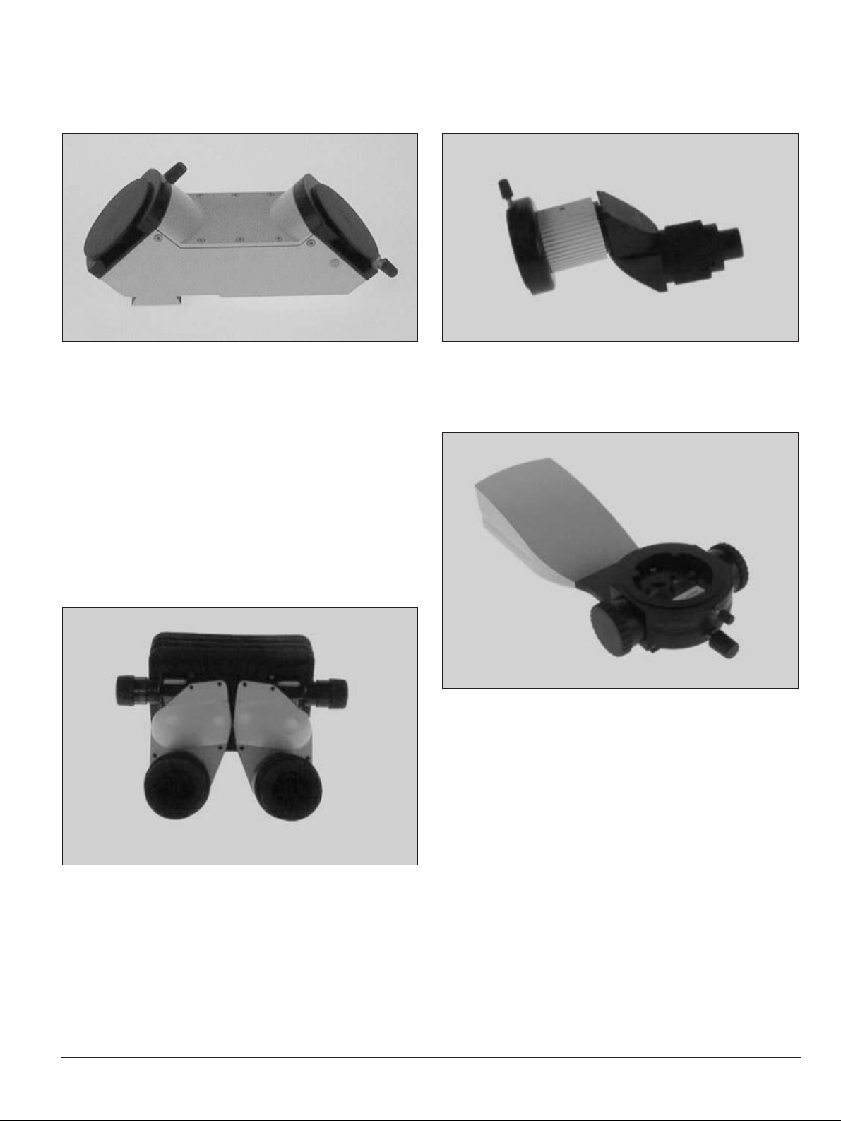
180° dual stereo attachment
• allows a second person to view
• attached to the optics carrier
The following can be attached to the 180° dual stereo
attachment:
• binocular tube, can be tilted 30°–150°
• beam splitter
• 30° rotating ring
• additional binocular tubes
Light distribution: 50 % on each side
Binocular tube; can be tilted; with
variable viewing angles 30°–150°
• with pupil-base adjustment for the eye-base
• focal length f = 170 mm
• integrated eyepieces with dioptre adjustment and built-in
eyecup adjustment
Stereo/second-observer attachment
• attached to beam splitter
Beam splitter with counterweight
• allows viewing by a second person or documentation
Light distribution: 50 % on each side
Page 34

Accessories
32
Leica M500 OH3 / Ref. 10 711 894 / Version -
Video-zoom tube
• attached to beam splitter
Adapter piece for accessories of the
M 600 series
• attached to beam splitter of M 500-N surgical microscope
Beam splitter
• allows viewing by a second person or documentation
Light distribution: 50 % on each side
Dual Imaging Color Module DI C500
• beam splitter with eight optical outputs
• built-in colour display superimposes data or video images
Ultra Observer ULT500
• beam splitter with eight optical outputs
ULT 500LEICA
Page 35
Accessories
33
Leica M500 OH3 / Ref. 10 711 894 / Version -
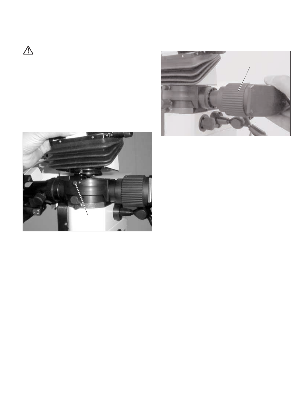
Mounting accessories
Warning
Risk of injury from tilting surgical microscope!
➩Never change the accessories or attempt to
rebalance the microscope while it is over the field of
operation.
➩Lock the Leica M500 OH3 each time before changing
accessories.
➩Balance out the Leica M500 OH3 each time after
changing accessories.
➩Do not release brakes in an unbalanced state.
Mounting 90° stereo attachment, binocular tube and beam
splitter
➩Loosen clamping screw (1).
➩Place accessory into the dovetail ring from above.
➩Tighten clamping screw (1).
1
Mounting stereo second-observer attachment and video-zoom
tube
➩Insert accessory and check whether the connection is
engaged.
➩Tighten locknut (2) by hand.
2
Page 36

Safety precautions
34
Leica M500 OH3 / Ref. 10 711 894 / Version -
The Leica surgical microscope is a state-of-the-art system.
Nevertheless, hazards may still arise during operation.
➩For this reason, you must always follow the directions given
in this user manual and particularly the safety precautions.
Intended use of instrument
• The Leica surgical microscope system is an optical
instrument which uses magnification and illumination to
improve the display of objects. It can be used for observation,
documentation as well as in human and veterinary surgery.
• The Leica surgical microscope is only to be used on a strong
floor in a closed room.
Directions for the person responsible for
the instrument
➩Ensure that the surgical microscope is used only by qualified
personnel.
➩Ensure that this user manual is always available at the place
where the surgical microscope is used.
➩Carry out regular inspections to make sure the user is
complying with safety requirements.
➩Brief the user thoroughly and explain the meaning of the
hazard signs and safety instructions.
➩Allocate responsibilities for getting the instrument ready for
work, for operating it and for maintaining it. Monitor
compliance with this.
➩Do not use the surgical microscope system unless it is in
proper condition.
➩If any faults develop which might put the safety of people at
risk, immediately contact your Leica representative or Leica
Microsystems (Switzerland) Ltd., BU SOM, 9435 Heerbrugg,
Switzerland.
➩If you use accessories from other manufacturers with the
Leica surgical microscope, ensure that the manufacturer
confirms that the combination is safe to use, and observe the
user manual.
➩Modifications and maintenance work may only be performed
by professionals expressly authorised by Leica.
➩When commencing maintenance work, only original Leica
parts are to be used.
➩After maintenance or technical modifications, the device
must be readjusted in accordance with our technical
specifications.
➩If the device is modified or maintenance has been performed
by unauthorised personnel, if the equipment is improperly
maintained (providing the maintenance was not performed by
us) or if the device has been operated improperly, Leica is
relieved of all liability.
➩The effect of the surgical microscope on other instruments
has been tested as specified in EN 60 601-1-2. The system has
passed the tests relating to emissions and immunity. Comply
with the usual precautionary and safety measures relating to
electromagnetic and other forms of radiation.
Directions for the user
➩Follow the instructions given in this manual.
➩Follow the instructions given by your employer regarding the
organisation of work and safety at work.
Page 37

Safety precautions
35
Leica M500 OH3 / Ref. 10 711 894 / Version -
Dangers of use
Warning
Risk of injury by:
• Uncontrolled swinging out of swing arm!
• Tilting of the stand!
• Feet in lightweight shoes can become trapped
beneath the base!
➩When transporting the surgical microscope, always
return it to the transport position.
➩Always push the surgical microscope; never pull it.
Caution
Microscope can be damaged by uncontrolled tilting
over!
➩Hold the handgrips firmly before pressing the ALL-
FREE button.
Warning
Mortal danger from electrical shock!
➩Connect the Leica M500 OH3 surgical microscope to
an earthed outlet only.
Warning
Risk of injury from tilting surgical microscope!
➩Never change the accessories or attempt to
rebalance the microscope while it is over the field of
operation.
➩Lock the Leica M500 OH3 each time before changing
accessories.
➩Balance out the Leica M500 OH3 each time after
changing accessories.
➩Do not release brakes in an unbalanced state.
Warning
Surgical microscope can move without warning!
➩Always set footbrakes, except during transport.
Warning
Risk of injury by movements of the microscope during
balancing out.
➩Do not remain in the immediate vicinity of the
microscope during balancing out.
Warning
Severe damage to tissue can result from an incorrect
working distance!
➩When working with lasers, always set the working
distance of the microscope to the laser distance and
lock it there.
Warning
Severe injury to tissue can result from manual
adjustment of the working distance!
➩The rotary knob may not be adjusted for manual
adjustment of the working distance while the laser is
in use.
Caution
Risk of infection!
➩Provide sufficient open space around the base to
prevent the sterile cover being touched by non-sterile
parts.
Caution
Zoom motor can be permanently damaged!
➩Only adjust the zoom manually if the zoom motor is
defective.
Caution
Risk of injury by falling wheel counterweight or cover!
➩During the change, ensure that your feet are not under
the wheel counterweight or the cover.
Caution
Risk of burns!
The lamp insert gets very hot.
➩Check that the lamp insert has cooled before you
remove the lamp.
Page 38
Safety precautions
36
Leica M500 OH3 / Ref. 10 711 894 / Version -
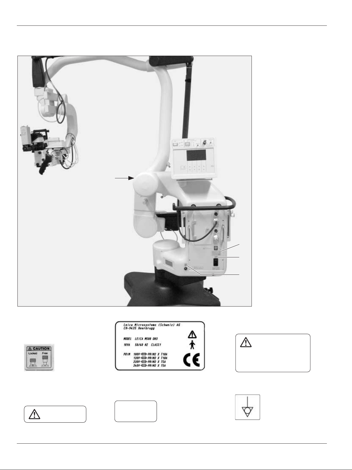
Labelling
13 5
(printed on)
24 6
(printed on)
Type 10448015
S/N TTMMJJxxx
Made in JP
1
2
3
4
DO NOT USE
IN OPHTALMOLOGY
Grounding reliability can
only by achieved when
EQUIPMENT is connected to
equivalent recentable marked
“Hospital only” or “Hosptial Grade”.
Page 39

Safety precautions
37
Leica M500 OH3 / Ref. 10 711 894 / Version -
13
2
1
2
3
2
Only to be operated
by trained personnel
Danger of
squeezing fingers
Page 40

Care and maintenance
38
Leica M500 OH3 / Ref. 10 711 894 / Version -
Care instructions
• Put a dust cover over the instrument during breaks in work.
• Keep accessories in a dust-free place when not in use.
• Remove dust with a pneumatic rubber pump and a soft brush.
• Clean the objectives and eyepieces with special optics
cleaning cloths and pure alcohol.
• Protect the surgical microscope from damp, vapours, acids,
alkalis, and corrosive substances.
Do not store chemicals near the instrument.
• Protect the surgical microscope from improper use.
The mounting of different plugs and the dismantling of optical
systems and mechanical components may only be carried out
if explicitly required by the instructions.
• Protect the surgical microscope from oil and grease.
Never oil or grease mechanical parts or sliding surfaces.
• Remove coarse debris with a moistened disposable cloth.
• For disinfecting the surgical microscope, use compounds
from the surface disinfecting group on the basis of the
following active ingredients:
- aldehyde,
- alcohol,
- quaternary ammonia compounds.
Due to possible damage of the materials, compounds
containing the following are not appropriate
• halogen-separated compounds,
• strong organic acids,
• oxygen-separated compounds.
Observe the directions of the manufacturer of the
disinfectant.
It is advisable to enter a service agreement with Leica
Service.
To retain the reliability of the surgical microscope, we
recommend inspecting the product annually covering our
detailed checklist.
Please contact your Leica Service representative.
Replacing lamps
➩Open access hatch (1) for lamp inserts.
The pushbutton for illumination (Item 6, Page 18) flashes
orange.
Caution
Risk of burns!
The lamp insert gets very hot.
➩Check that the lamp insert has cooled before you
remove the lamp.
➩Pull out defective lamp insert (2 or 4) and insert new lamp
insert (spare part No. 10 448 022).
When inserting the lamp insert, ensure that the arrow
(3) points to the right.
➩Close access hatch again.
The pushbutton for illumination (Item 6, Page 18) goes out.
1
2
3
4
Page 41
Care and maintenance
39
Leica M500 OH3 / Ref. 10 711 894 / Version -
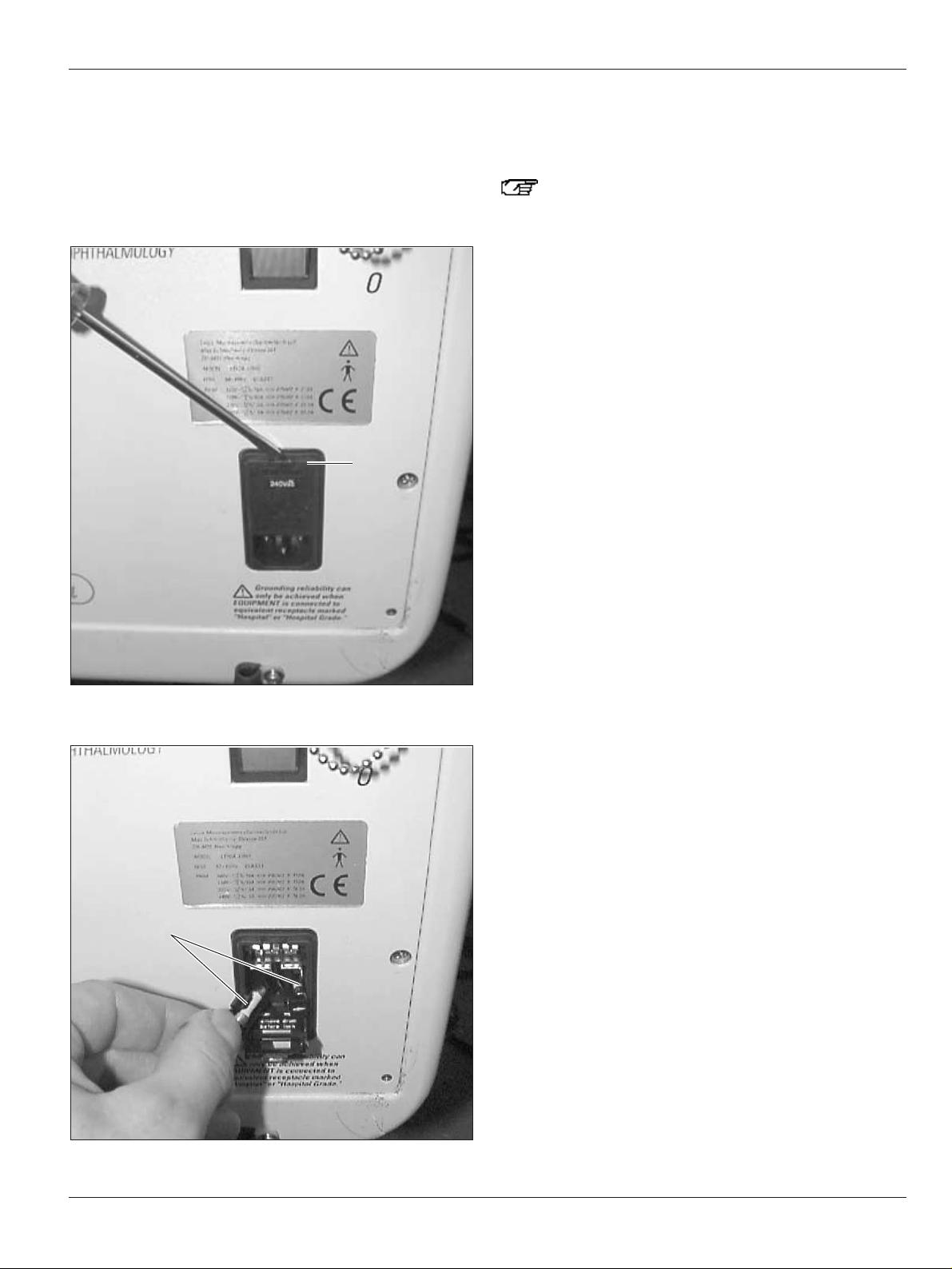
Replacing fuses
220 V–240 V range: two 5-A fuses, slow blow
100 V–110 V range: two 10-A fuses, slow blow
➩Remove cover (1) with screwdriver.
➩Remove fuses (2) from the fasteners and replace them.
2
1
Operational check
Illumination
Always allow the main and backup illuminators to
remain lit for at least five minutes, otherwise the
lighting capacity will be quickly reduced.
➩Switch on the power switch.
➩Check main illuminator and backup illuminator.
➩Switch back to main illuminator and switch off illumination.
Footswitch
➩Position footswitch.
➩Test all functions with the footswitch.
Page 42

What to do if...?
40
Leica M500 OH3 / Ref. 10 711 894 / Version -
General faults
If the device no longer functions properly,
please contact your Leica representative for advice.
Fault Cause Remedy
The microscope tilts when the The microscope carrier is not ➩Balance out microscope carrier
ALL-FREE button is pressed. balanced properly. (see Page 15).
The microscope cannot be moved, A cable is clamped. ➩Re-lay the affected cable.
or great force is required to move it.
The Leica M500 OH3 is locked. ➩Release lock (see Page 14).
The functions cannot be actuated A cable connection has come loose. ➩Check the power cable.
with footswitches or the controller ➩Check footswitch connection.
at the handgrips.
Assignment entered incorrectly at the ➩Change the assignment by means of the
control unit. control unit.
No light in microscope. The fibre-optic light guide has detached. ➩Check connection of fibre-optic light guide.
Main and/or backup illuminator defective. ➩Switch to other illumination (see Page 18).
The image does not remain sharp. Eyepieces not properly seated. ➩Screw eyepieces down completely.
Dioptrics not set correctly. ➩Perform dioptre correction exactly
according to the instructions (see Page 21).
The microscope or swing arm moves Swing arm not balanced out correctly. ➩Balance out the Leica M500 OH3
up and down or rotates on its own. (see Page 15).
Cables not laid properly or have moved ➩Lay cables according to installation
and are putting a strain on the system instructions and relieve tension.
(possibly an additional video cable).
Leica M500 OH3 was balanced out ➩Release locks (see Page 14) and balance
while locked. out Leica M500 OH3 (see Page 15).
Microscope and microscope carrier Automatic balancing was not ➩Ensure that position B was reached
can only be moved with great force or completed. (Page 15/16).
not at all. ➩Press the pushbutton for auto balance
again.
Page 43

What to do if...?
41
Leica M500 OH3 / Ref. 10 711 894 / Version -
Fault Cause Remedy
Automatic balancing cannot be Microscope tilted too severely. ➩Align A/B axes parallel at microscope
performed. (see Page 15).
➩Perform automatic balancing again.
Protective flap at pushbutton for auto ➩Flip up protective flap and press
balance was not flipped up before pushbutton for auto balance.
pressing.
Zoom cannot be adjusted electrically. Failure of zoom motor. ➩Press zoom pushbutton.
➩Adjust zoom by rotating it (see Page 28).
No XY movement possible at one of the Settings in control unit for joystick of ➩Set joystick to XY movement (see Page 26).
two handgrips. effected handgrip are at DIC.
The microscope is not balanced out Mounted accessory was not turned back ➩Balance out B axis again.
exactly in the B axis. to the working position during balancing Ensure that the accessories are turned
out of the B axis. back to the working position during
balancing out of the B axis (see Page 16).
Swing arm cannot be moved. Swing arm locked. ➩Release lock (see Page 14).
The stand of the Leica M500 OH3 moves. Footbrakes not locked. ➩Engage footbrakes (see Page 14).
The range of movement of the Cables laid to tightly. ➩Lay cables again (see Leica M500 OH3
Leica M500 OH3 is limited (swivelling, installation instructions).
tilting, rotating, XY movement).
Video camera was not mounted properly ➩ Mount video camera correctly.
and touches the microscope carrier.
Leica M500 OH3 is not balanced out Position of accessories was changed ➩Balance out the Leica M500 OH3
properly. after balancing out. (see Page 15).
Leica M500 OH3 cannot be balanced out. Wheel counterweight used on the D axis ➩Change wheel counterweight on the
cannot compensate for the mounted D axis (see Page 30).
accessories.
Leica M500 OH3 was balanced out in the ➩Take the Leica M500 OH3 out of the
transport position. transport position and balance it out
again (see Page 15).
Page 44

What to do if...?
42
Leica M500 OH3 / Ref. 10 711 894 / Version -
Fault Cause Remedy
The image becomes blurry when the Parfocality not precisely set. ➩Set individual dioptre values of
magnification is changed. the operating doctor (see Page 24).
Focus at microscope cannot be changed. Switch for multifocal focus switched on. ➩Switch off multifocal focus (see Page 19).
Exception: You are working with a laser
micromanipulator, at which this function
was set for protection.
The image appears darkened through Accessories not mounted precisely. ➩Mount accessories exactly
the microscope at the edge and the in the holders (see Page 33).
illumination field is outside the field of view.
TV, photography
Fault Cause Remedy
Photographs/TV images blurry. Microscope or video zoom adapter not ➩Focus precisely; use a graticule if
precisely focussed. necessary.
➩Perform dioptre correction exactly
according to the instructions.
The photographs have a bluish cast. The wrong film type was used. ➩Use daylight film.
Error messages at control unit
Fault Cause Remedy
Microscope needs initialisation Microscope initialisation has failed. ➩Select «Initialise microscope» in
main menu 2 and confirm with «ok».
Microscope initialisation failed Microscope initialisation has failed. ➩Select «Initialise microscope»
in main menu 2 and confirm with «ok».
No status response from microscope Connection from stand to microscope ➩Check connection cable and replace if
interrupted, connection cable defective. necessary.
Page 45

Technical data
43
Leica M500 OH3 / Ref. 10 711 894 / Version -
Electrical data
Power connection for
Leica M500 OH3: 1000 VA 50/60 Hz
100 V (+10 %/–15 %)
120 V (+10 %/–15 %)
220 V (+10 %/–15 %)
240 V (+10 %/–15 %)
Protection class: class 1
Protection type: type B
Leica M500 N
Microscope
Magnification changer: zoom 6:1, motor-driven
Working distances: 207–407 mm; motor-driven multifo-
cal eyepiece; continuously adjustable; can be adjusted manually
Focusing: with motor-driven multifocal
eyepiece; can be adjusted
manually
Eyepieces: wide-field eyepieces for spectacle
wearers 10x; 12.5x
dioptre adjustment ±5 dioptres;
with adjustable eyecup
Objectives: multifocal eyepiece; working
distance – continuously adjustable
from 207–407 mm (with motor)
Illumination: to the illumination system adapted
for microsurgery; diameter and
brightness of the illumination field
with manually-variable zoom optics
Main illuminator and backup illuminator: high-power 300 W xenon
lamp; entirely independent electrically; brightness control via sixstep rotary switch at constant
colour temperature
Microscope control unit: graphical LCD with background
lighting; individual user settings
can be saved for up to eight users;
in-built self-diagnosis system
Optical data
Total magnification: with 10x eyepiece: 1.4x to 13.7x
Field of view (dia. in mm): with 10x eyepiece: 16 to 150
Microscope carrier
Rotation range: 540°
Balancing: ABC axes fully automatic, each can
be corrected manually
Brakes: one brake for A/B axis
one brake for C axis
Fibre-optic cable
Length: 4500 mm
Active diameter: 7 mm
Minimum bending radius: 35 mm
Accessories
Binocular tube: variable viewing angles 30°–150°;
in-built eye-base adjuster with
fixed setting to 45° or variable
viewing angles 0°–180°
Beam splitter: two side outlets with light distribu-
tion 50 % to 50 % or 70 % to 30 %
Video-zoom tube: zoom 3:1; focal lengths 35–100 mm;
with C mount;
can be focussed individually
Viewing by a second 180° dual stereo attachment with
person: light distribution 70 % to 30 % or
stereo second-observer
attachment for beam splitter
or Leica ULT500
or Leica DI C500
Page 46

Technical data
44
Leica M500 OH3 / Ref. 10 711 894 / Version -
Floor stand
Model: floor stand with fully-automatic
balancing system and six
electromagnetic permanent
magnetic brakes
Use: carries and positions the Leica
M500 N surgical microscope
Brakes: six electromagnetic brakes; actua-
tion via pushbutton on handgrip
Balancing: automatic balancing in all axes and
directions
Handgrips: zoom adjustment
working distance adjustment for
multifocal objective
ALL-FREE button releases all six
brakes on stand
side selector button configurable
with three user-defined brakes
motorised XY adjustment or
navigation of DI C500 functions via
joystick
Stand control unit: main/backup illuminator
triggering automatic balancing
status display of balancing
manual balancing of D axis
setting XY speed
switchover FOCUS LOCK - XYZ
FREE
Load: min. 8.0 kg and max. 11.7 kg from
dovetail microscope interface
Space requirement: Foot: 720 x 720 mm
min. height in parked position:
1850 mm
Weight: approx. 266 kg with full load
Range: Cantilever: max. 1520 mm
Standards
EN 60601-1
EN 60601-1-2
UL 2601-1
Environmental conditions
Use: +10 °C to +40 °C
+50 °F to +104 °F
30 % to 95 % relative humidity
500 mbar to 1060 mbar air pressure
Storage: –40 °C to +70 °C
–40 °F to +158 °F
10 % to 100 % relative humidity
500 mbar to 1060 mbar air pressure
Limitations on use
The Leica M500 OH3 is only for use in closed rooms and on a
strong floor.
Page 47
Technical data
45
Leica M500 OH3 / Ref. 10 711 894 / Version -
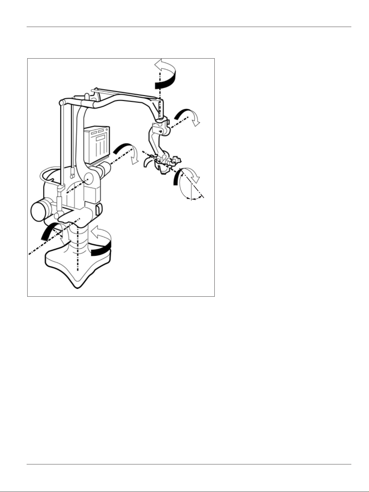
Dimensional drawings
360°
± 40°
± 40°
± 50°
± 150°
± 270°
(120°)
(30°)
Page 48
Technical data
46
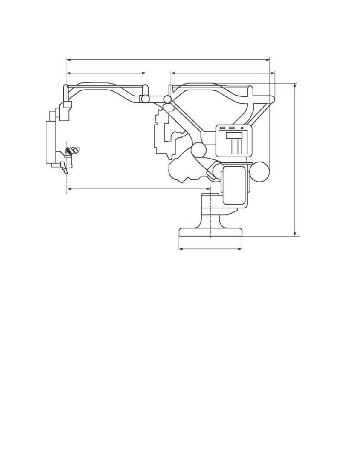
Leica M500 OH3 / Ref. 10 711 894 / Version -
2350
930 1220
max. 1520
720 x 720(mm)
1850
Page 49

Technical data
47
Leica M500 OH3 / Ref. 10 711 894 / Version -
1170
250
1855
Page 50

Notices
48
Leica M500 OH3 / Ref. 10 711 894 / Version -
Page 51

Notices
49
Leica M500 OH3 / Ref. 10 711 894 / Version -
Page 52

Leica Microsystems – the brand
for outstanding products
Leica Microsystems – an international company
with a strong network of customer services
Australia Gladesville, NSW Tel. + 61 2 9879 9700 Fax + 61 2 9817 8358
Canada Richmond Hill Tel. +1 905 762 20 00 Fax +1 905 762 89 37
China Beijing Tel. +86 10 684 92 698 Fax +86 10 684 92 965
Denmark Herlev Tel. +45 4454 0101 Fax +45 4454 0111
France Rueil-Malmaison Cédex Tel. +33 1 473 285 85 Fax + 33 1 473 285 86
Germany Bensheim Tel. +49 6251 136 0 Fax + 49 6251 136 155
Hong Kong Tel. +85 22 56 46 699 Fax +85 22 56 441 63
Italy Milan Tel. +39 0257 4861 Fax +39 0257 40 3273
Japan Tokyo Tel. + 81 3 5435 9609 Fax + 81 3 5435 9614
Korea Seoul Tel. +82 2 514 65 43 Fax +82 2 514 65 48
Portugal Lisbon Tel. +35 1 21 388 9112 Fax + 35 1 21 385 4668
Singapore Tel. +65 6779 7823 Fax +65 6773 0628
Spain Barcelona Tel. +34 93 494 95 30 Fax +34 93 494 95 32
Switzerland Glattbrugg Tel. +41 1 809 34 34 Fax + 41 1 809 34 44
United Kingdom Milton Keynes Tel. + 44 1908 66 66 63 Fax + 44 1908 609 992
USA Allendale/New Jersey Tel. +1 201 23 65 900 Fax +1 201 23 65 908
and representatives of Leica Microsystems
in more than 100 countries.
Leica Microsystems’ Mission is to be the world’s first-choice provider of innovative
solutions to our customers’ needs for vision, measurement, lithography and analysis
of microstructures.
Leica, the leading brand for microscopes and scientific instruments, has developed
from five brand names, all with a long tradition: Wild, Leitz, Reichert, Jung and
Cambridge Instruments. Leica symbolizes not only tradition, but also innovation.
The Business Unit SOM, within Leica
Microsystems, holds the management
system certificates for the international
standards ISO 9001 and ISO 14001 / EN 46001
relating to quality management, quality
assurance and environmental management.
EU-Authorized representative:
Leica Microsystems Holdings Ltd
DE-35578 Wetzlar
Tel. +49 6441-290, Fax +49 6441-29 33 99
The companies of the Leica Microsystems
Group operate internationally in five business
segments, where we rank with the market
leaders.
Microscopy
Our expertise in microscopy is the basis for all
our solutions for visualization, measurement
and analysis of microstructures in life sciences and industry.
Specimen Preparation
We specialize in supplying complete solutions
for histology and cytopathology.
Imaging Systems
With confocal laser technology and image
analysis systems, we provide three-dimensional viewing facilities and offer new solutions
for cytogenetics, pathology and material sciences.
Medical Equipment
Innovative technologies in our surgical microscopes offer new therapeutic approaches in
microsurgery. With automated instruments for
ophthalmology, we enable new diagnostic
methods to be applied.
Semiconductor Equipment
Our automated, leading-edge measurement
and inspection systems and our E-beam
lithography systems make us the first choice
supplier for semiconductor manufacturers all
over the world.
Leica Microsystems (Schweiz) AG
Business Unit SOM
Max Schmidheiny-Strasse 201
CH-9435 Heerbrugg
Telephone +41 71 726 33 33
Fax +41 71 726 32 19
www.leica-microsystems.com
www.surgicalscopes.com
Illustrations, descriptions and technical data are not binding and may be changed without notice.
© Leica Microsystems (Schweiz) AG • CH-9435 Heerbrugg, 2002
Art. No. 10 711 894 – Version - – Printed in Switzerland – en – XI.2002 – RDV
 Loading...