

Page 1
Service manual Leica M500 N, M520,
M525
10 665 751 – Release 09/2007
Table of contents
1. Technical Description
2. Wiring Diagram and Locations
3. Service Programs
4. Fault Finding
5. Replacing Modules
6. Maintenance Service
7. Inspection
8. Spare Parts
Page 2

Release 09/2007
• First edition
Page 3

Service manual Leica M500 N, M520, M525 Description
Doc Code 10 665 751
1-I
08/2007 Gahe
1. Description - Leica M500 N, M520, M525
Table of content
Chapter Page
System description 1-1
General 1-1
Overview control unit 1-1
Overview optics carrier 1-2
Electrical accessories 1-3
Optical/mechanical accessories 1-3
Configuration M525 systems 1-4
Product history M500 N…M525 1-5
Electrical description 1-7
General 1-7
CAN bus 1-8
Optics carrier 1-9
Control unit 1-11
Technical data M525 1-13
Page 4

Description Service manual M500 N, M520, M525
08/2007 Gahe
1-II
Doc Code 10 665 751
Page 5
Service manual M500 N, M520, M525 Description
Doc Code 10 665 751
1-1 08/2007 Gahe
Description of the Leica M500 N, M520, M525
System description
General
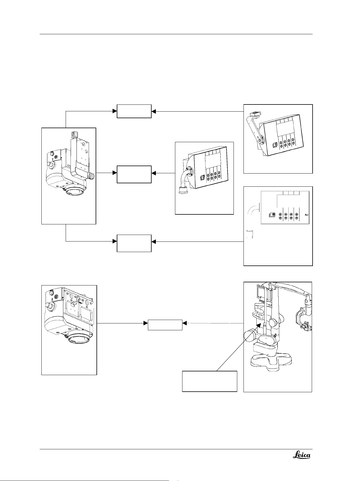
The Leica M500 N / M520 /M525 surgical microscope is an optical instrument which uses magnification and
illumination to improve visibility. It is dedicated mainly for Neurosurgery discipline.
The microscope is always used together with a Leica stand system – refer to product history on page 1-5.
Electrically the optics carrier and the control unit are connected together to the stand system by the CAN bus.
Newer generations of stand systems (like OH4) have their own MDC (microscope device controller) and take over the
task of the M500 N control unit.
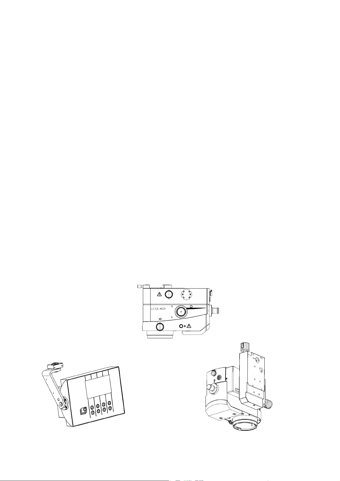
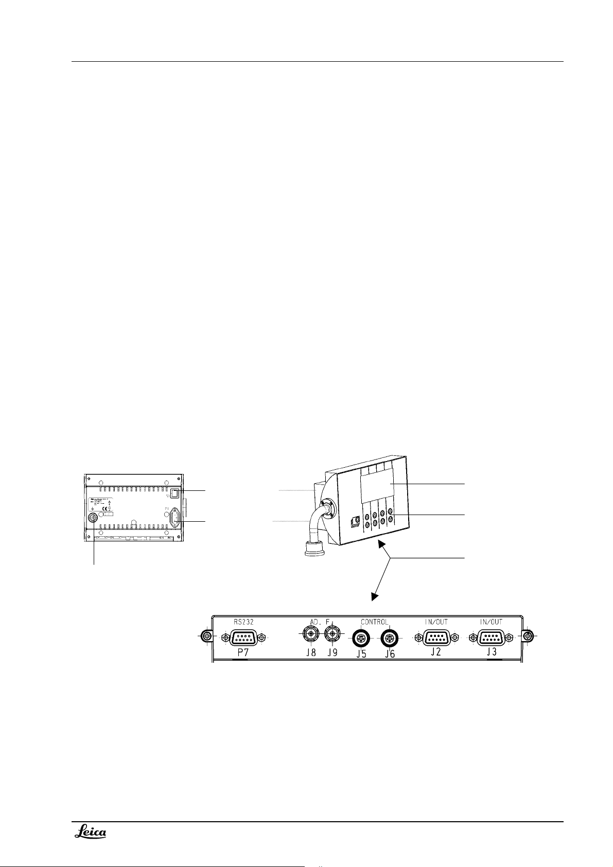
Overview control unit M500 N / M520
Grounding socket*
* Only for control
unit with internal
power supply
Power switch*
Power inlet*
Display
Switch panel
with 9 keys
Electrical
interfaces
Page 6
Description Service manual M500 N, M520, M525
p
1-2
08/2007 Gahe
Doc Code 10 665 751
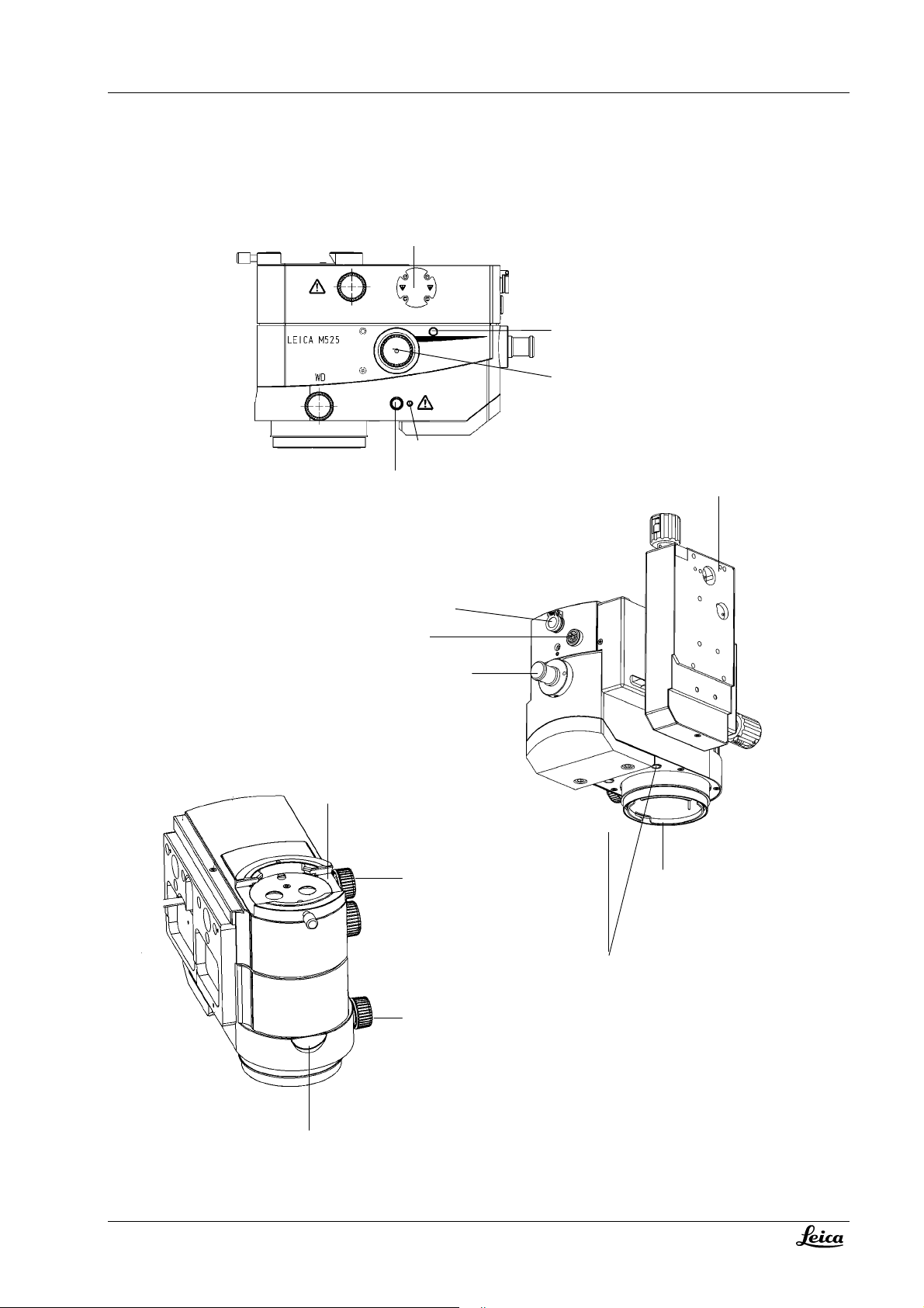
Overview optics carrier M525
Handgrip interface
M525 only: Iris reset
Drive illumination diaphragm
(M525: Iris override)
LED WD lock indication
WD lock button
A/B slide
Service & CAN res
CAN interface
Fiber optics interface
Dovetail interface
Manual drive zoom
Interface for
rotective glass
Laser interface
Manual drive WD
Display WD (M520/M525)
Page 7

Service manual M500 N, M520, M525 Description
Doc Code 10 665 751
1-3 08/2007 Gahe
Electrical accessories
- All Leica hand- and footswitches fit to the control unit M500 N / M520 (restriction for 16 function switch – it is
handled as a 12 function switch only)
- CAN handle
- DI C500
- Autofocus device
- Fluorescence devices (available for some stand systems only)
Optical/mechanical accessories
- All optical equipment with dovetail interface fit to the optics carrier. Refer to appropriate stand user manual
for allowed loads and configurations
- Interface for protective glass 10 446 058
- Interface for universal Laser adapter 10 448 079 (M520 & M525)
- Interface for universal Laser adapter 10 446 615 (M500 N)
- Sterilisable knobs
- Interface for right handgrip
- Interface for fiber optic
Page 8
Description Service manual M500 N, M520, M525
(
)
y
1-4
08/2007 Gahe
Doc Code 10 665 751
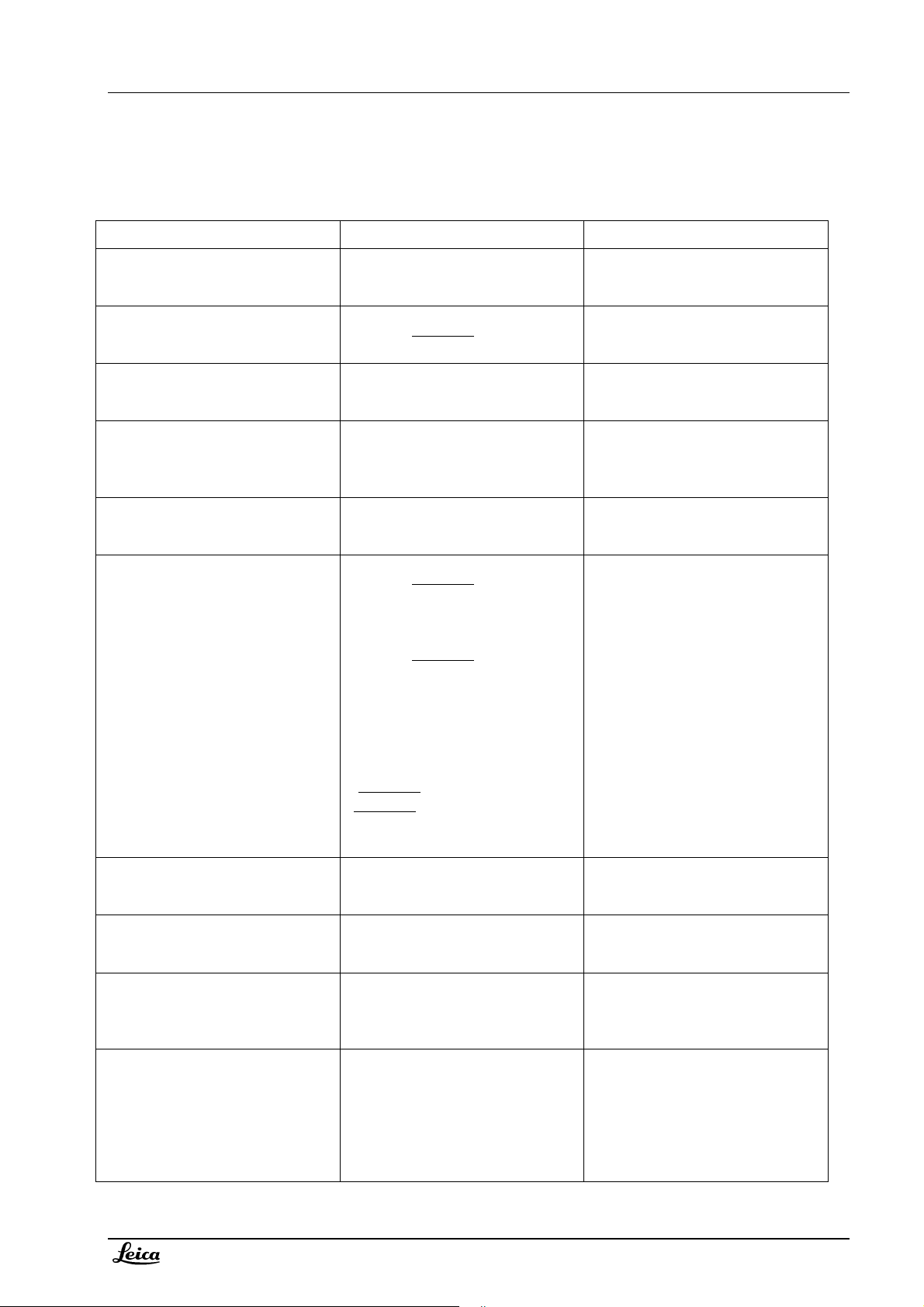
Current configurations Leica M525 (state 08/2007)
10448237 M525
optics carrier
(with A/B-slide)
10448238 M525
optics carrier
no A/B slide
M525 F40
M525
M525 MC1
M525 OH4
10448169 control
unit
Control unit M520 not used
anymore - a new controller
is integrated
in OH4 system
10448068 control unit
10448144 control
unit
10448236 OH4
stand s
stem
Page 9
Service manual M500 N, M520, M525 Description
Doc Code 10 665 751
1-5 08/2007 Gahe
Product history Leica M500N - M520 - M525
Date / event Description: Remark
1997 / Launch M500 N
02/2001 / product change in optics
carrier
07/2001 / Launch with MS2
11/2002 / Launch with OH3
04/2003 / Launch with MS3 10 446 757 M500 N optics carrier
10/2003 / Product change in optics
carrier: New M520 optics carrier
07/2004 / Launch M520 F40 10 448 029 M520 optics carrier for
03/2005 Product change of control
unit: removed power supply
09/2005 Product launch M520 C40
and CT40
07/2006 Product change in M520
optics carrier
10 446 481 M500 N optics carrier
10 446 489 control unit
10 446 757 M500 N optics carrier
replaces 10 446 481
10 446 757 M500 N optics carrier
10 446 489 control unit
10 711851 control unit for OH3
10 448 019 M500 N optics carrier
(without A/B slide)
10 446 489 control unit
10 448 029 M520 optics carrier
replaces 10 446 757
OHS1;
10 448 035 M520 optics carrier
(without A/B slide) for OH3
replaces 10 448 019
Upgrade kit was available:
10 712 316, upgrade kit M500 N to
M520 optics carrier; description 10
665 687;
(10 446 757
10 448 019
F40, 10 448 068 control unit for F40
10 448 144 control unit replaces
10 446 489
10 448 029 M520 optics carrier and
new control unit 10 448 169 for C40
and CT40
10 448 029 M520 optics carrier and
10 448 035 M520 optics carrier
with new zoom unit
to 10 448 070;
to 10448 071)
for MS2, MS3,
;
For stand systems OHS1, MS1,
MC1
New emergency drive for zoom
Additional for MS2 stand system
Additional for OH3 stand system
Additional for MS3 stand system
New illumination unit and new
multifoc objective : More light
30%, increased working distance
from 407 to 470mm, display for
working distance, improved
illumination optics – lead free
glass.
Zoom unit : new diaphragm (10 712
255) for better depth of field reduced diameter to 12mm.
New Lemo plug instead fixed CAN
cable – external cable required.
For stand systems OH3, OHS1,
MS3, MS2, MS1, MC1
Control unit without power supply
and with new holder
All stand systems from 03/2005 on
can provide 24V;
Control unit compatible, but with
new holder
Paint on zoom lenses as a
diaphragm
Page 10

Description Service manual M500 N, M520, M525
1-6
08/2007 Gahe
Doc Code 10 665 751
09/2006 Product change to M525
optics carrier
10 448 237 M525 optics carrier
replaces 10 448 029
for MC1, F40,
MS3, C40, CT40
10 448 238 M525 optics carrier
(without A/B slide) replaces
10448 035
for OH4
Upgrade kit available for limited
time:
10 714 461 Upgrade kit M520 to
M525; description 10 665 743
(10 448 029
10 448 035
to 10 448 246;
to 10 448 247)
New illumination unit, additional
AutoIris function, new motor
controller, removed illumination
zoom.
For stand systems OH4, MS3, MC1,
F40, C40, CT40
Page 11
Service manual M500 N, M520, M525 Description
A
A
Doc Code 10 665 751
1-7 08/2007 Gahe
Electrical description
General
The optics carrier is a high performance operating microscope with adjustable working height and integrated zoom,
with M525 also an integrated autoIris. The zoom- and the focus functions, for M525 also the Iris functions, are
microprocessor controlled in order to give the user the maximum comfort. The electronics in the optics-carrier
consists of only one board, with the microprocessor, memory, motorcontrollers and interfaces on it.
A control unit is needed to store the settings, to read hand/footswitches and to control the optics- carrier, manage
CAN bus activities and to display the status/settings. It consists of one controller board, called control module, a LCD
module and a switch panel. Former control units contain a power supply as well.
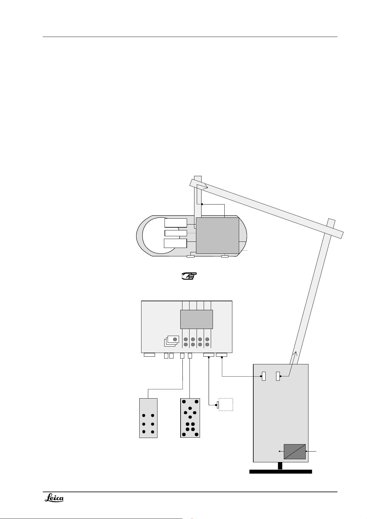
Overview of system:
*Possible options on
CAN bus:
-
CAN handle
-
DI C500
-
Autofocus
-
Swing carrier
-
Fluorescence
Optics-carrier
Zoom
Iris
Multifoc
P7
RS-232
Service
dd.
Funktion
Hand/Footswitch
MF off
Control unit
J5
J9 J8
CAN-Bus
P2
P8
P4
P5
P6
P9
Iris c ont rol
P10
Option*
CAN-Res.
Service
CAN-Bus
P7
P1
P3
Iris function (P8, P9, P10): only in M525
J6
CAN
CAN-Bus
+24V
CAN
DC
C
max 240VAC
External. CAN
modul
CAN
CAN
Leica Stand
Page 12

Description Service manual M500 N, M520, M525
08/2007 Gahe
CAN bus
CAN-bus principle
The CAN-bus (Controller Area Network) is a bi-directional, two-wire bus. It is used to handle the communication
between the control unit, the optics-carrier, the stand and other CAN devices. The CAN-bus uses a protocol which
largely suppresses transmission errors.
The CAN bus in the M500 N/M520/M525 system is operated in the configuration “standard – CAN”.
Data transfer
The bus is looped through each of the controllers. Data is transferred serially, bit by bit, with differential signals. The
data transfer is rated at with 50kBit/s.
The data can be exchanged between each of the controllers. A data transfer consists of:
• Start bit,
• Identification, enabling the priority to be determined,
• The data itself, and
• CRC (Cyclic Redundancy Check).
Each controller recognizes the data related to its task. If a controller wants to send data, it has to wait until the bus is
free. The feature of setting the priority of commands is not applied in the M500 N/M520/M525 system; all commands
have the same priority.
Command interpretation by control unit
The control unit reads CAN commands from CAN handles and from other CAN members. It interprets the received
commands and releases appropriate commands to the CAN bus. The concerning CAN device will then release a
required action.
Safety concept - brake watch dog
The control unit must periodically (100ms) send a brake state message. If no periodic brake state message is received
by the connected stand/brake controller, all brakes will lock.
Terminating impedance
In control unit: the end of the CAN-bus is terminated with an impedance of 120Ω. The controller detects if it is at the
end of the bus or if another device is connected (CAN cable is coded: Pin 4 is bridged to pin 8 in the connector
housing).
In optics carrier: the controller of the optics carrier is always terminated by 120Ω; other devices, connected to the bus
at the optics carrier are not terminated.
1-8
Doc Code 10 665 751
Page 13

Service manual M500 N, M520, M525 Description
Doc Code 10 665 751
1-9 08/2007 Gahe
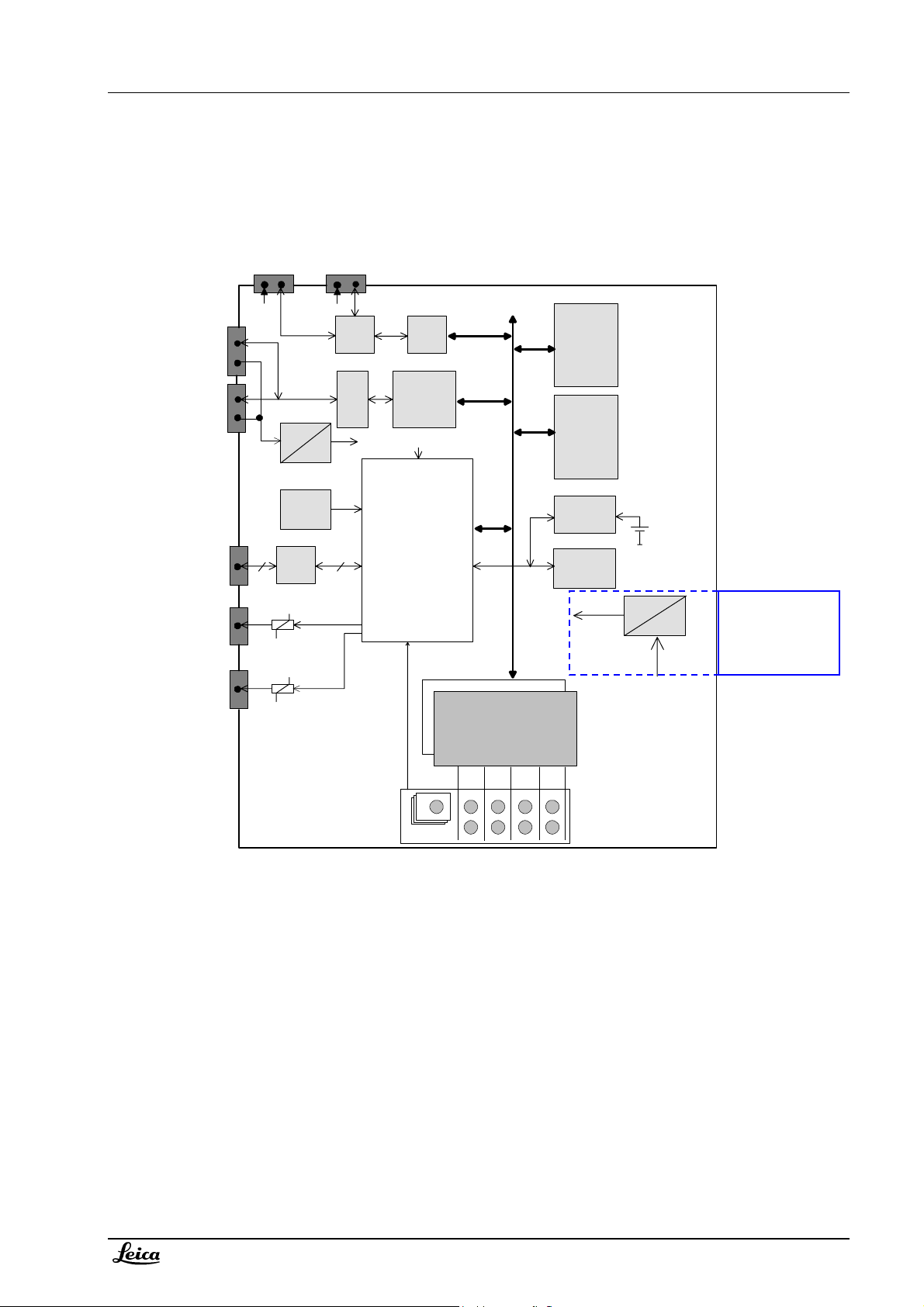
Optics carrier
Blockdiagram motorcontroller M500 N, M520
P2
CAN
CAN-Res.
P3
Reset
EEPROM
P6
MF off
P7
Option
24V
120E
5V
CANTrans.
5V
CANController
82527
On-chip
RAM
1kx8
Prozessor
H8/532
On-chipPeripherals,
Watchdog
SCI
PWM
PWM
EPROM
128Kx8
MEM3200
Universal
Counter
ZoomMotor Driver
MultifocMotor Driver
P4
Zoom
P5
Multifoc
+24V
+24V
P1
Service
motcontr.ds4
Addition for motorcontroller M525:
P10
CAN
PWM
Iris
Motor Driver
+24V
P8
Iris
Iris control
P9
Powering
The optics-carrier is powered via the CAN-bus cable with +24VDC.
Power consumption is appr.
50mA in wait state,
150mA when one motor is running;
500mA when both motors, focus and zoom are blocked.
A DC/DC converter on the motorcontroller delivers +5V for logic supply. The +24VDC is measured on the controller
board with the microprocessor analog input. It can be asked in the diagnostic menu of the control unit.
Page 14
Description Service manual M500 N, M520, M525
1-10
08/2007 Gahe
Doc Code 10 665 751
Processor
A watch-dog is integrated in the H8-processor. It observes the running of the main program. Diagnosis LED’s might
help with trouble shooting, refer to chapter 4 – fault finding / diagnosis LED’s.
The PWM outputs are driven with the optimum frequency of 20kHz (above the noise-limit, below magnetization
problems).
Motor driver
The zoom- , focus and Iris motors are powered with a +24V PWM-signal. A one-chip controller receives enable-,
direction- and the puls-rate-information from the processor and drives the motors accordingly. All motors have an
encoder mounted directly on the motor axis. The encoder pulses are received by a counter, where the A/B-signals
(direction) are decoded and the actual position transferred further to the processor. A current limitation for the motors
becomes active for current > 0,3A.
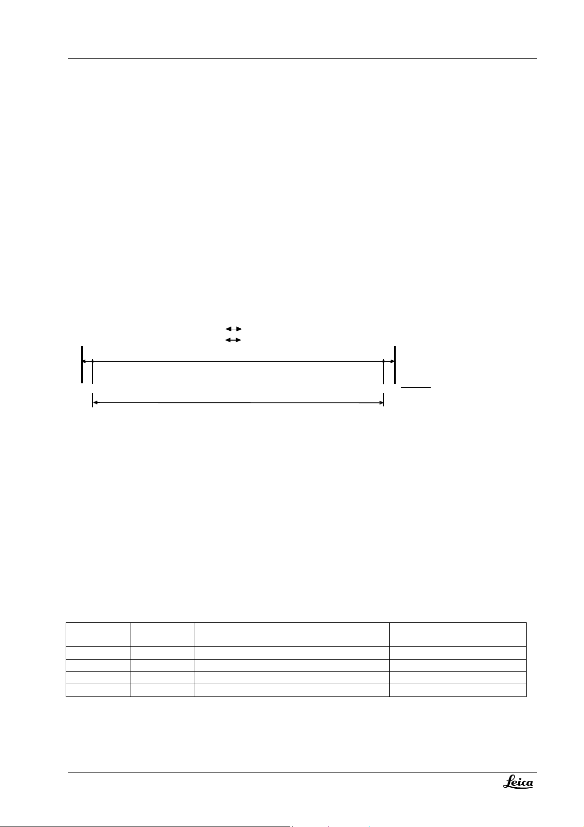
Range
The initializing of the microscope sets the lower limit to 1000 encoder-pulses. The actual upper limit is determine with
counting the encoder-pulses (constants are stored for these values; deviations of the displayed values are possible
due to mechanical tolerances).
Focus 207mm
Zoom OU T Zoom IN
UP
DOWN UP
Focus 407mmDOWN
or 470mm (M520, M525)
800
1000
working range
upper limit
range.ds4
Zoom: 28500
Focus: 23800
RS232
A serial interface for service purposes is available. It is directly wired to the Optics-carrier processor - and has
therefore other signal level for TxD than RS232 standard.
Recognition of optics carrier type
Since the increase of the working distance from 407 to 470mm (M500 N to M520) a recognition of the optics carrier
type is required. A bridge on P6 (pin1-pin4) is installed in optics carrier M520 and M525. A status command, requested
from control unit at system start , delivers the information if the bridge is installed or not.
Additional functionality on motorcontroller for M525
The AutoIrsis function in the M525 required an additional motor and a redesign of the motorcontroller. All existing
functions were taken over (backwards compatible) and additional circuits for Iris motor drive and Iris control were
integrated. The movement of the Iris motor is completely handled by the motorcontroller, no direct access via the CAN
bus is possible.
Software history
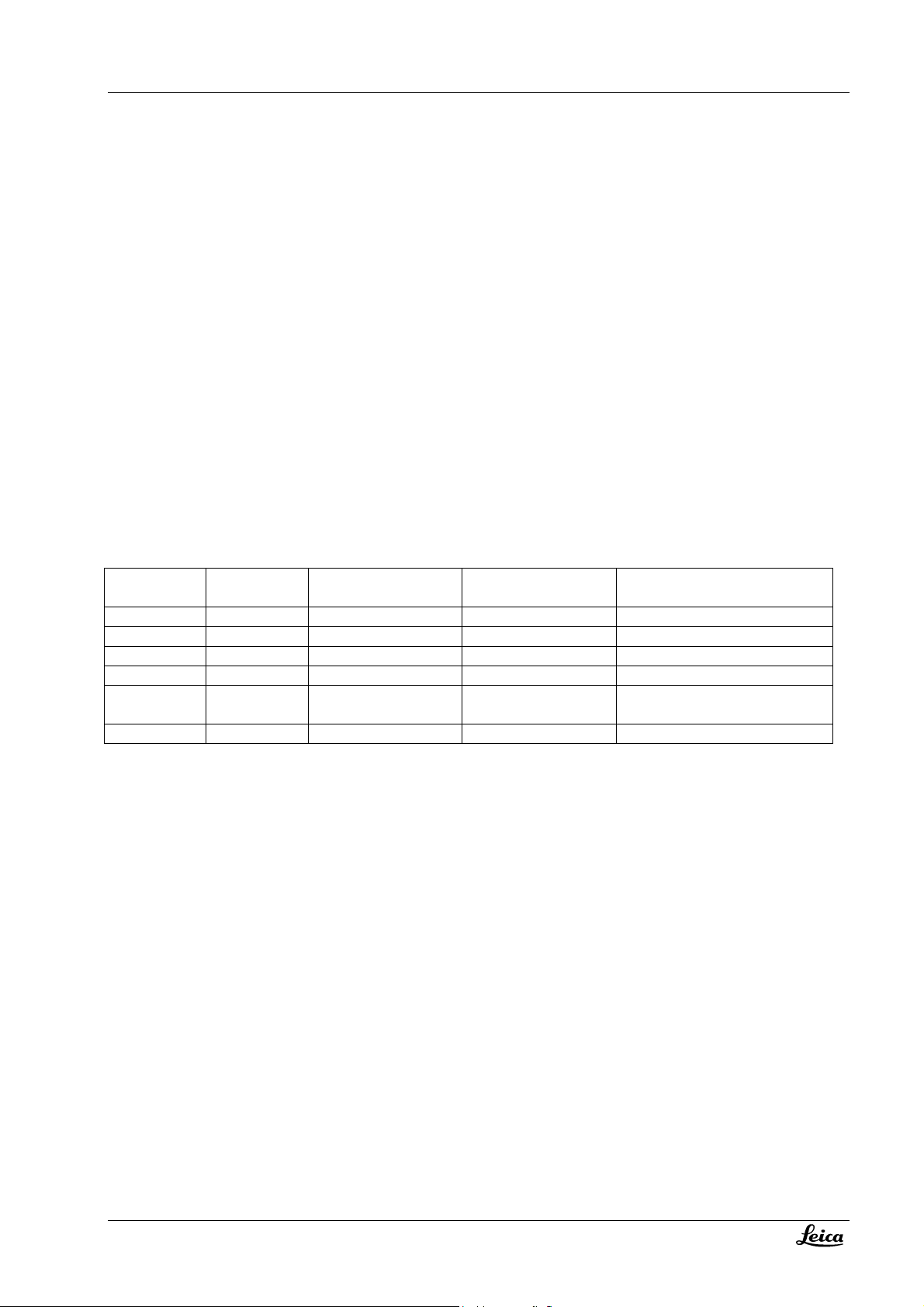
Software
Release date HW motorcontroller Compatibility Remark
version
1.4 02/98 10 661 250 M500 N
2.3 04/99 -“- M500 N
2.4 05/01 -“- M500 N, M520
4.4 xx/06 10 714 356 M500 N, M520, M525
Software compatibility in respect of control unit see chapter inspection / step 2.13.
Page 15
Service manual M500 N, M520, M525 Description
A
r
Doc Code 10 665 751
1-11 08/2007 Gahe
Control unit
Blockdiagram
Hand-/Footswitch 1 and 2
J5
J6
CANBus
J2
5V
CANBus
J3
Service,
Download
P7
2
RS232
Relay
contact
Relay
contact
J8
J9
5V
24V
5V
Watchdog
Timer
RS232
CANTrans.
5V
386EX CPU,
2
PLD Glue Logic,
Bus Transceivers
DUART
CANController
82527
40MHz
CLK2
Processor
J10
LCD - Graphic Controlle
J11
LCD - Display
240 x 128 Dots
with VF-backlight
RAM
256kByte
FlashEPROM
256KByte
Power-off
Timer
EEPROM
4 kByte
+24V
max 230V AC
DC
"Gold"-
capacitor
C
Power supply
removed since
03/2005
Function
keys
steuerge.ds4
Powering
Control units before 03/2005 had a power inlet for 230VAC ad the built-in power supply could feed the system with
+24VDC. This was required in stand systems having no own power supply like the MC1.
Since 03/2005 all stand systems have their own power supply. So the power supply was removed from control unit,
now it is supplied via the CAN bus cable with 24VDC.
Processor
An Intel 386EX Processor is used. It is clocked with 20MHz. The memory consists of 256kByte RAM, 256kByte FlashEPROM and 4kByte EEPROM. The software can be updated/downloaded through the RS232 service-interface.
A watch-dog is integrated, it observes the running of the main program. Diagnosis LED’s might help with trouble
shooting, refer to chapter 4 – fault finding / diagnosis LED’s.
Page 16
Description Service manual M500 N, M520, M525
08/2007 Gahe
Display / Keyboard
The communication with the user is done with help of an high-contrast display and a keyboard with nine keys. The
display is a LCD Matrix (240x128 dots) with integrated Graphic controller and backlight.
Can-bus
The CAN-bus has two go-through-input/outputs with two identical parallel connectors.
Hand/Footswitch
There are two RS232 interface-connectors available for all available hand / footswitches. They are wired to the
DUART-interface and are clocked with 4800 Baud. The control unit periodically (60ms) sends a request to the
connected footswitch. It sends back a status code (2 Byte), indicating which key is pressed/not pressed.
Service interface
A double RS232 interface is provided for service purposes. They are both wired directly to the Processor (RXD0/TXD0,
RXD1/TXD1) The connector P7 is used for both of them. COM1 (RXD0/TXD0) is programmed for a service-terminal, for
example for downloading new software version into the Flash-EPROM.
Additional function
There are two relay-contacts on the control unit connector panel for additional functions. The maximum permissible
loading for one contact is 1 A/24 V DC. The relay-contacts can be programmed to switch- or toggle mode.
Software history
Software
version
1.4 02/98 10 661 330 M500 N
1.54 01/00 -“- M500 N
1.76 04/02 -“- M500 N Supports Can handles, DI C500
1.81 -“- M500 N Supports OH3
1.84 -“- M500 N Supports MS3, CAN handle can
1.87 -“- M500 N, M520, M525 Supports M520, M525
Software compatibility in respect of optics carrier see chapter inspection / step 2.13.
Release date HW control module Compatibility Remark
1-12
Doc Code 10 665 751
be configured separate
Page 17

Service manual M500 N, M520, M525 Description
Doc Code 10 665 751
1-13 08/2007 Gahe
Technical data
Optics carrier M525
Stock n° 10448237 M525 optics carrier
10448238 M525 optics carrier OH4
Zoom 6:1 zoom, motorized
Magnification Total magnification with 10x eyepiece 1,2 x to 12,8
Working distance 207-470 mm, variable through motorized multi-focal lens, continuously adjustable;
manually adjustable by emergency knob
Display Analog display of working distance
Field of view (diameter) 16,5mm to 180 mm with 10x eyepiece
Objective Multi-focal lens 207-470 mm variable working distance
Illumination Continually adjustable illumination field diameter with gauss-shaped light distribution
AutoIrisTM Built-in automatic zoom-synchronized illumination filed diameter with manual override and
reset feature
Outlet interface Dovetail ring
Control unit M500 N/M520
Stock n° 10448169 (M525 C40/CT40)
10448068 (M525 F40)
10448144 (MC1, MS3)
Display LCD display
Adjustment of Speed for zoom and focus, brightness and backlight intensity of display, WD and zoom
Interfaces RS232 for service
2x RS232 for foot/handswitch
2x additional function (programmable relay contact)
CAN port Two CAN-ports, 24V max 50W
Page 18

Description Service manual M500 N, M520, M525
08/2007 Gahe
1-14
Doc Code 10 665 751
Page 19

Service manual Leica M500 N, M520, M525 Wiring
Doc Code 10 665 751
-I
2
07/2007 Gahe
2. Wiring and locations Leica M500 N, M520, M525
Table of content
Chapter Page
Optics carrier 2-1
Control unit 2-4
Overview of connectors 2-6
Wiring diagrams 2-8
Wiring diagram M525 719072 2-9
Wiring diagram M500 N / M520 707276 2-11
Page 20

Wiring Service manual M500 N, M520, M525
07/2007 Gahe
2-II
Doc Code 10 665 751
Page 21
Service manual M500 N, M520, M525 Wiring
Doc Code 10 665 751
2-1 07/2007 Gahe
Wiring and locations Leica M500 N, M520, M525
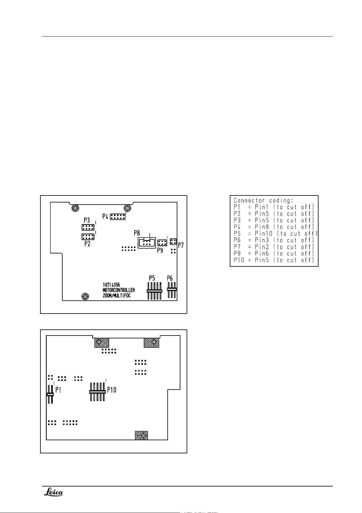
Optics carrier
Zoom/multifoc motor controller 10714356
Page 22
Wiring Service manual M500 N, M520, M525
2-2
07/2007 Gahe
Doc Code 10 665 751
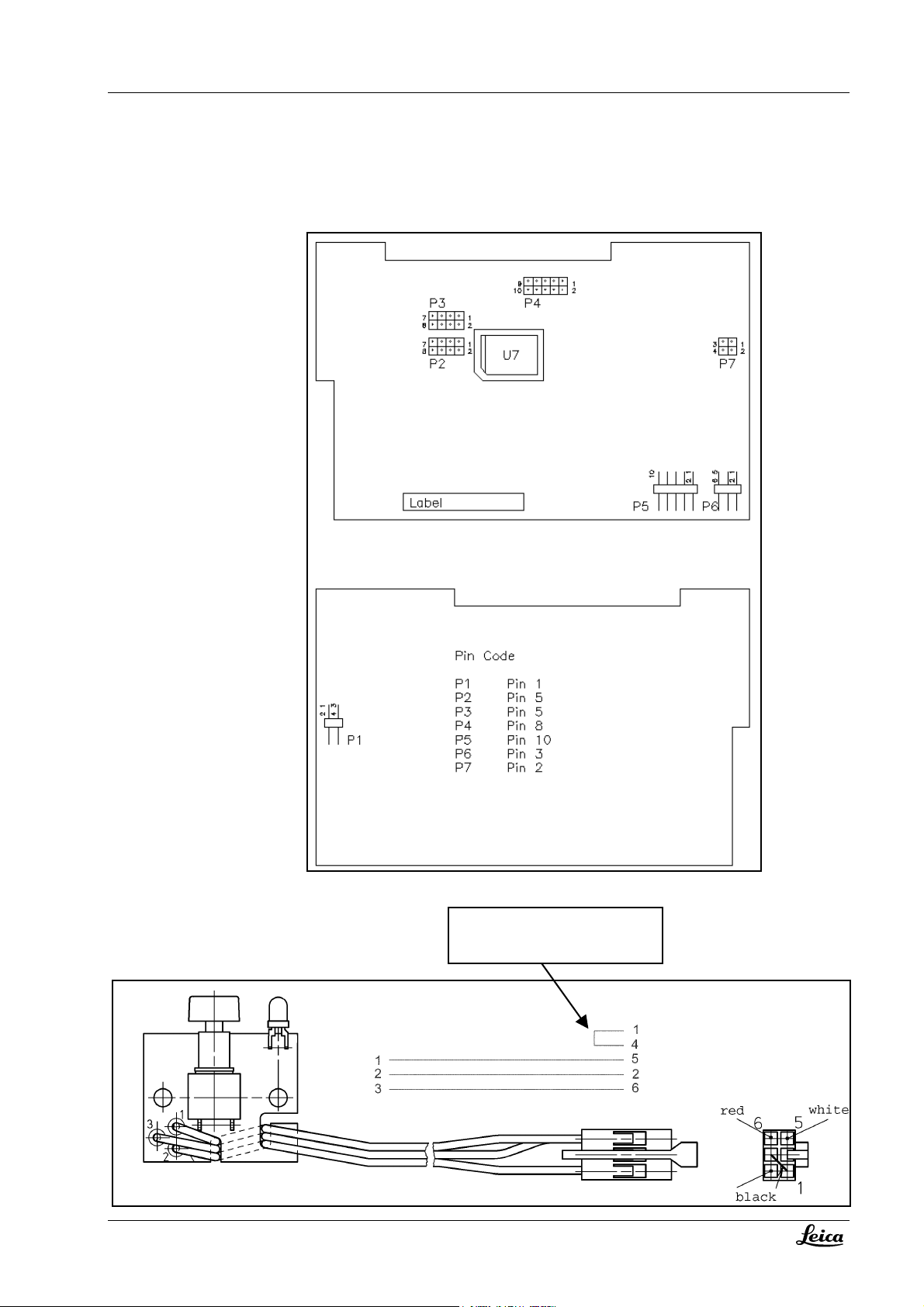
Zoom/multifoc motor controller 10661250 (M500 N/M520 only)
Bridge for M520/M525 only;
Removed when used in M500 N
Switch board
J6
View from
wiring side:
Page 23
Service manual M500 N, M520, M525 Wiring
Doc Code 10 665 751
2-3 07/2007 Gahe
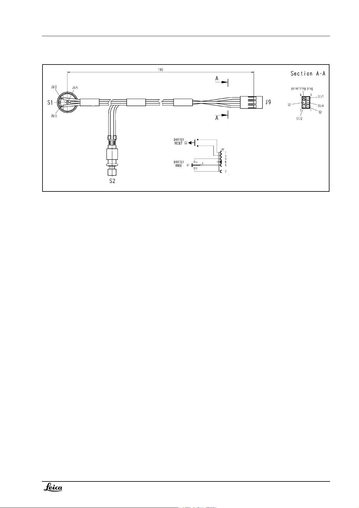
Iris switch assembly
Page 24
Wiring Service manual M500 N, M520, M525
07/2007 Gahe
2-4
Doc Code 10 665 751
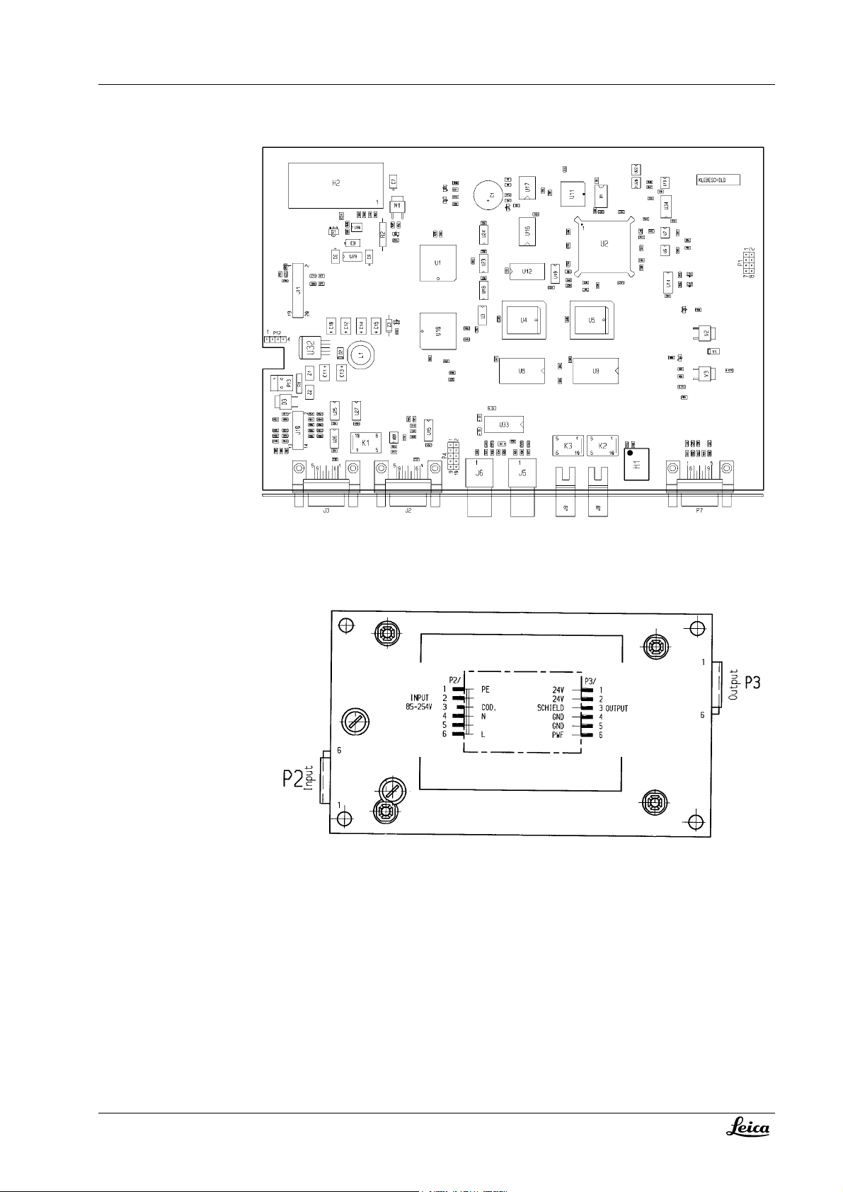
Control unit
Control module
Power supply (only in control units till March 2005)
Page 25
Service manual M500 N, M520, M525 Wiring
Doc Code 10 665 751
2-5 07/2007 Gahe
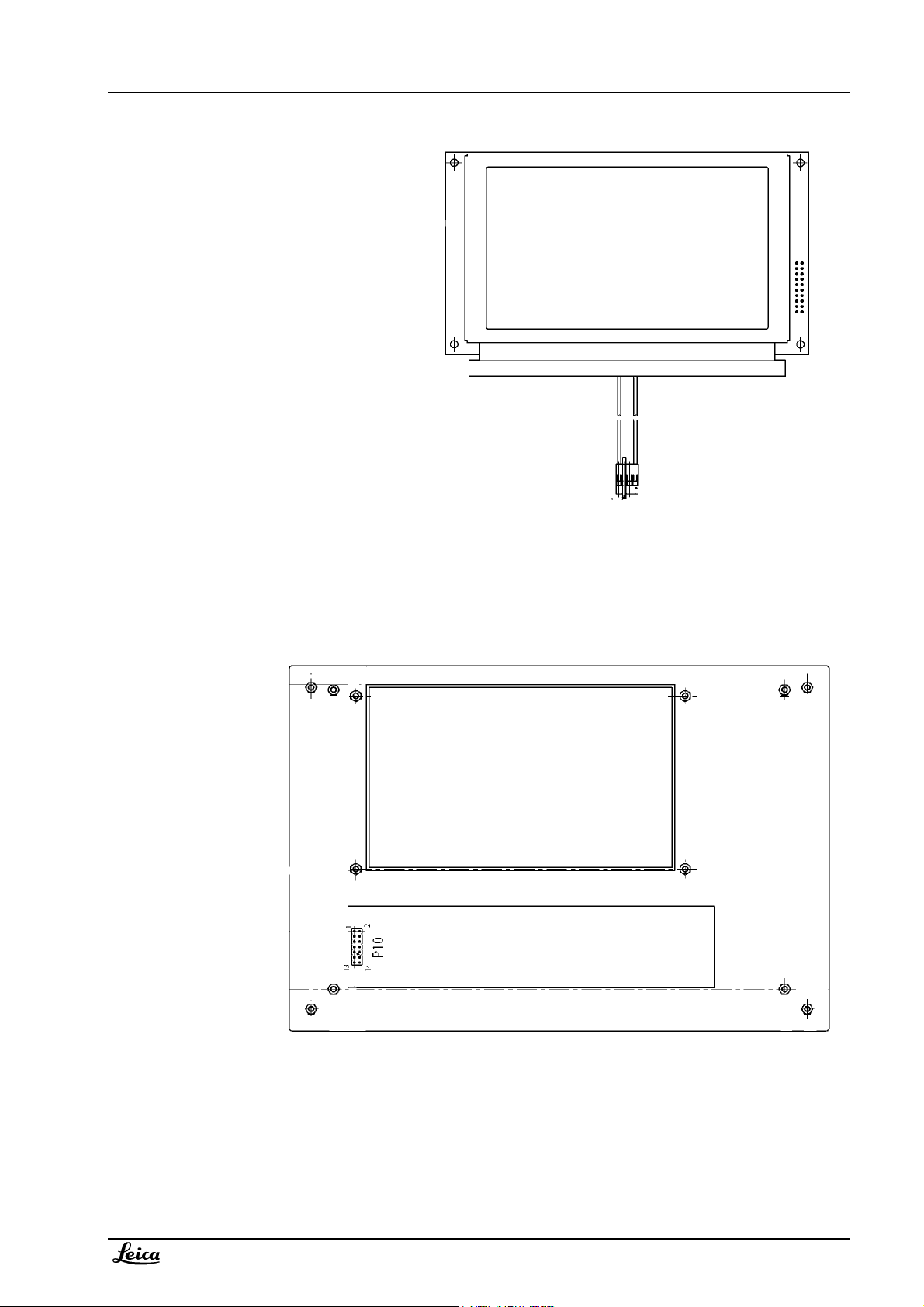
LCD module
P11
J12
Switch panel
Page 26
Wiring Service manual M500 N, M520, M525
07/2007 Gahe
2-6
Doc Code 10 665 751
Overview of connectors
Connector Page Module / connecting to
Optics Carrier
P1 2-1, 2-2 Motor controller / service port
P2 2-1, 2-2 Motor controller / CAN
P3 2-1, 2-2 Motor controller / CAN res.
P4 2-1, 2-2 Motor controller / zoom motor
P5 2-1, 2-2 Motor controller / focus motor
P6 2-1, 2-2 Motor controller / switch board
J6 2-2 Switch board
P7 2-1, 2-2 Motor controller / Res.
J7 - Optics carrier / Service/CAN res. (Lemo with cap)
P8 2-1 Motor controller / Iris motor
P9 2-1 Motor controller / Iris switch assembly
J9 2-3 Iris switch assembly
P10 2-1 Motor controller / CAN (to stand system)
Control unit
P1 2-4 Control module / test port (not used)
P2 2-4 Power supply / input power
J2 2-4 Control module / CAN1
P3 2-4 Power supply / output power
J3 2-4 Control module / CAN2
P4 2-4 Control module / not used
J5 2-4 Control module / remote 1
J6 2-4 Control module / remote 2
P7 2-4 Control module / service RS232
J8 2-4 Control module / add. function 1
J9 2-4 Control module / add. function 2
J10 2-4 Control module / switch panel
P10 2-5 Switch panel / control module
P11 2-5 LCD module / control module
J11 2-4 Control module / LCD module
Page 27

Service manual M500 N, M520, M525 Wiring
Doc Code 10 665 751
2-7 07/2007 Gahe
P12 2-4 Control module / LCD module backlight
J12 2-5 LCD module /control module
P13 2-4 Control module / input from power module
Page 28

Wiring Service manual M500 N, M520, M525
07/2007 Gahe
2-8
Doc Code 10 665 751
Wiring diagrams in A3 format
Wiring diagram M525 10719072 on page 2-9
Wiring diagram M500 N/M520: 707276 A on page 2-11
Page 29

Service manual M500 N, M520, M525 Wiring
Doc Code 10 665 751
2-9 07/2007 Gahe
Page 30

Wiring Service manual M500 N, M520, M525
2-10
07/2007 Gahe
Doc Code 10 665 751
Empty page: reversed side of wiring diagram
Page 31

Service manual M500 N, M520, M525 Wiring
Doc Code 10 665 751
2-11 07/2007 Gahe
Power supply removed since 03/2005
Page 32

Wiring Service manual M500 N, M520, M525
2-12
07/2007 Gahe
Doc Code 10 665 751
Empty page: reversed side of wiring diagram
Page 33

Service manual Leica M500 N, M520, M525 Service programs
Doc Code 10 665 751
3-I
08/2007 GAHE
3. Service programs - Leica M500 N, M520, M525
Table of content
Chapter Page
Service programs control unit 3-1
Software upgrade program for control unit and optics carrier 3-3
Page 34

Service programs Service manual Leica M500 N, M520, M525
08/2007 GAHE
Stock n° Description / Specification Remark Drawing
3-II
Doc Code 10 665 751
Page 35

Service manual Leica M500 N, M520, M525 Service programs
Doc Code 10 665 751 3-1 08/2007 GAHE
Stock n°. Description / Specification Remark Drawing
Service programs – Leica M500N, M520, M525
Service programs in control unit
How to enter the service functions:
• Enter the service menu of the M500 N/M520 control unit in menue II
• Enter security code: 6642
• Select the service functions
Validity
Below description refers to SW 1.87 in the control unit and 2.4 or 4.4 in optics carrier.
Service function
Standard and user configuration Settings of user- and standard
Ad. Function 1 output configuration The output of additional function 1 can
Ad. Function 2 output configuration The output of additional function 2 can
Screen saver setting Screen saver for control unit display:
User parameter save time setting When user settings are saved, the
Power off timer setting A power off / power on within the
Description Remark
Refer to stand user manual.
configuration can be changed and
stored.
Switch mode: relais contact closes
be set and stored either to toggle or to
switch mode.
be set and stored either to toggle or to
switch mode.
after the selected time the brightness
will be reduced.
display shows “User setting saved at…”
for a certain time; this time can be
altered.
selected time will effect:
The last selected user (before switching
off) is automatically taken as the actual
user.
as long as the release button is
pressed.
Toggle mode: relais contact
opens/closes with each activation of
the release button.
-“-
Adjustable between 0..60 minutes.
Default = 5 minutes.
0 minutes will disable screen saver.
Adjustable between 2..6 seconds.
Default = 4 seconds.
Adjustable between 0..60 minutes.
Default = 5 minutes.
Page 36

Service programs Service manual Leica M500 N, M520, M525
08/2007 GAHE
3-2
Doc Code 10 665 751
Stock n° Description / Specification Remark Drawing
Service function
Description Remark
User selection timer setting During the power up routine the control
unit allows to select a user; if no user is
Adjustable between 2..20 seconds.
Default = 11 seconds.
selected within a certain time it will take
the standard settings.
Tube focal length setting The setting influences the displayed
magnification value in the main menu.
Adjustable between 100..200.
Set to focal length of main tube.
Default = 170.
Exception reboot timer setting If an error causes an exception reboot of
the control unit, the error can be
Adjustable between 0..20 seconds.
Default = 10 seconds.
displayed for a certain time before the
reboot starts.
Set device list Connected CAN devices have to be set
to “present”.
Not connected CAN devices have to be
set to “Not present”.
If the device list is not set correctly, it
may result in malfunction and/or
error messages. Available CAN
devices:
Stand (M500-N)
Microscope (M500-N)
Microscope (M500-O)
X/Y-Unit (M500-O)
Autofocus (M500-N)
Handle R (M500-N)
Handle L (M500-N)
DI control (M500-N)
Swing carrier (MS3)
Restore factory defaults All standard and user settings will be
reset to the factory default values.
All user settings will be lost.
Autofocus setup Autofocus video parameters and
autofocus range parameters are set in
Details in service manual
BIV/Autofocus 10 665 645.
this menu.
Stand setup Opens a monitor for entering setup /
service program of the connected stand
Details in the appropriate stand
service manual.
system.
DI Default Settings Shutter functions and shutter mode are
set in this menu.
Details in service manual Neuro
modules 10665683.
DI Color LCD Module Settings Video parameter for the LCD display of
the DI-module are set in this menu.
Details in service manual Neuro
modules 10665683.
Page 37

Service manual Leica M500 N, M520, M525 Service programs
(J7)
Doc Code 10 665 751 3-3 08/2007 GAHE
Stock n°. Description / Specification Remark Drawing
Software upgrade program
Software update for control unit
The M500 N/M520 control unit allows a SW update by Laptop/PC. The control unit can be set into a service mode.
In this mode the control unit accepts data via the RS232 service interface (P7). An update program, running on a
PC/laptop sends the SW via serial port (RS232).
Technical details:
RS232-parameter 19200/8/1/no; transmit and receive signals RS232 compatible;
RS232
Download cable control unit 10 710 562
Software update for optics carrier
The M500 N/M520/M525 optics carrier allows a SW update by Laptop/PC. The motorcontroller accepts data via the
RS232 service interface (either at the capped Lemo plug J7 or the internal plug J1). An update program, running on
a PC/laptop sends the SW via serial port (RS232).
Technical details:
RS232-parameter 19200/8/1/no; receive signal RS232 compatible; transmit signal 0...5V (HCMOS)
CAN/Service
port J7
Download cable optics carrier 10 710 563
Software update procedure
Refer to update description (doc code10 665 668).
The content of the Update CD is available on the intranet as well.
PC/Laptop
Win 95/98/2000/NT/ME/XP
Program Update Center
(on Update CD 10 712 463)
COM port
PC/Laptop
Win 95/98/2000/NT/ME/XP
Program Update Center
(on Update CD 10 712 463)
COM port
Page 38

Service programs Service manual Leica M500 N, M520, M525
08/2007 GAHE
3-4
Doc Code 10 665 751
Stock n° Description / Specification Remark Drawing
Page 39

Service manual Leica M500 N, M520, M525 Fault finding
Doc Code 10 665 751
4-I
08/2007 Gahe
4. Fault finding - Leica M500 N, M520, M525
Table of content
Chapter Page
Diagnosis LED 4-3
Start-up sequence 4-6
Error messages 4-7
Diagnostic functions in control unit 4-12
Page 40

Fault finding Service manual M500 N, M520, M525
08/2007 Gahe
4-II
Doc Code 10 665 751
Page 41

Service manual M500 N, M520, M525 Fault finding
Doc Code 10 665 751
4-3 08/2007 Gahe
Fault finding - M500 N, M520, M525
Diagnosis LED’s
Zoom/multifoc motor controller 10714356
LED 1 green Watchdog - blinking with 2Hz,
LED 2 red
LED 3 yellow
LED 4 green
indicates that the main program is
running.
Enable zoom - “On” when the zoom
motor is driven or short-circuited
(damaged). “Off” when the motor is
set free.
Enable multifoc - “On” when the
multifoc motor is driven or shortcircuited (damaged). “Off” when
the motor is set free.
+5V-Powering - “On” when the
switching regulator is working.
LED 4
LED 3LED 2LED 1
Page 42

Fault finding Service manual M500 N, M520, M525
08/2007 Gahe
Zoom/multifoc motor controller 10661250 (M500 N/M520 only)
LED 1 green Watchdog - blinking with 2Hz,
LED 2 red
LED 3 yellow
LED 4 green
indicates that the main program is
running.
Enable zoom - “On” when the zoom
motor is driven or short-circuited
(damaged). “Off” when the motor is
set free.
Enable multifoc - “On” when the
multifoc motor is driven or shortcircuited (damaged). “Off” when
the motor is set free.
+5V-Powering - “On” when the
switching regulator is working.
4-4
Doc Code 10 665 751
LED 4
LED 3 LED 1LED 2
Page 43

Service manual M500 N, M520, M525 Fault finding
Doc Code 10 665 751
4-5 08/2007 Gahe
Control module
LED1 green Watchdog LED - blinking when
LED2 red Not used.
LED3 green Indicates the presence of +5V.
the main program is running.
LED 3 LED 2LED 1
Page 44

Fault finding Service manual M500 N, M520, M525
t
t
q
)
4-6
08/2007 Gahe
Doc Code 10 665 751
Start-up sequence
Validity
Below description refers to SW 1.87 in the control unit and 2.4 or 4.4 in optics carrier.
Optics-carrier: Control-unit:
Initializing motor controller
Initializing microscope motors (zoom and focus drive
into their lower limit; M525 also Iris motor – drives to
most open limit)
YES
Parameters
received from
control unit?
NO
Motors move to their start positions
(defined in user settings)
NO
Start
position
reached?
YES
Display last user “User name Activating user parameters”
Parameters are sent to optics
carrier
Ready
Ready - Display of the main menu
Initializing processor
Display „RTKernel-32 Debug version“
Display “M500 N/M520 N software version 1.87”
Display “Initializing”
uesting version of optics carrier (M500 N or M520 or none
Re
YES
Display “Presetting Optic Carrier defaults”
Resetting of values for total magnification, working
distance and auto focus to the standard values of the
recognized optics carrier (user settings are lost!!)
Requesting of: IGS company ID & IGS calibration code from optics carrier
Requesting of other CAN devices
Power off/on
YES NO
ime < setting in
service menu ?
After x seconds
(User selection
imer)
Display “Standard setting Activating user parameters”
Parameters are sent to optics
carrier
Display selected “User name Activating user parameters”
Parameters are sent to optics
carrier
Request for confirming of IPD,
diopter, eyepiece mag
Optics carrier
version different
configuration
Display “Select User”
NO
to last
Any “user”
selected by
operator (key
pressed) ?
?
NO
YES
Page 45

Service manual M500 N, M520, M525 Fault finding
Doc Code 10 665 751
4-7 08/2007 Gahe
Error messages
Error messages are displayed on the control unit. For systems without using the control unit - like
M525 OH4 – refer to the appropriate service manuals (chapter fault finding and service programs).
Different levels of error messages
Level-1 error messages:
If a Level-1 error-message occurs, it will be shown in the second line of Menu I or Menu II.
The error message persists unless an appropriate action has been performed. If more than one error messages are
present, then each message is visible for a few seconds in an endless loop.
Example Menu II:
Standard setting
Microscope needs initialization
User settings
Initialize microscope
Service Menue
up/down
Level-2 error messages:
If a Level-2 error-message occurs, it will be shown in the second line in the Service Menu. Level-1 messages are
displayed here as well.
The error message persists unless an appropriate action has been performed – or the message has been cleared in
the service menu. If more than one error messages are present, then each message is visible for a few seconds in an
endless loop.
Example Service Menu:
System config./Standard setting
CAN warning 1: 96 communication errors
Select language
Service functions
Diagnostic functions
Clear error messages
up/down
Menue II
Select function
ok cancel
ok cancel
Page 46

Fault finding Service manual M500 N, M520, M525
4-8
08/2007 Gahe
Doc Code 10 665 751
Error list in diagnostic menu
All error-messages are stored in an error-list. How to display the error list - refer to chapter “Diagnostic function
control unit”.
Error interpretation
Restrictions and remarks:
Below description refers to SW 1.87 in the control unit and 2.4 or 4.4 in optics carrier.
Error messages caused by the Iris diaphragm in M525 optics carrier are NOT displayed in M500 N / M520 control unit.
Level-1 messages are underlined
, all others are Level-2 messages.
MF means multifoc controller / motor controller .
Error messages caused by the optics carrier:
Error message
Description Remedy
Microscope error/warning out of
range
Control unit received an unknown error
code from optics carrier.
Check compatibility of software in
control unit with software in optics
carrier.
Microscope needs initialization
Power-up-reset happened to optics
carrier; therefore motor positions are not
defined.
Release “initialize microscope” in
menu II.
Microscope initialization failed Initializing command, sent to optics
carrier, is not executed within 45
seconds.
If no problem with CAN
communication it is a problem of
motor controller in optics carrier.
Activating user parameter failed Motor positioning commands, sent to
optics carrier, are not executed within 45
seconds.
If no problem with CAN
communication it is a problem of
motor controller in optics carrier.
No status response from
microscope
Microscope detected (config. error) Optics carrier was found on CAN bus,
No status response from optics carrier
within 5 seconds.
although it is set to NOT PRESENT.
If no problem with CAN
communication it is a problem of
motor controller in optics carrier.
Set optics carrier in device list
PRESENT.
Microscope not detected (config.
error)
IGS Calibration Code setting error Problem writing IGS calibration code to
Optics carrier was not found on CAN
bus, although it is set to PRESENT.
optics carrier.
Set optics carrier in device list
NOT PRESENT.
• SW in optics carrier must be
2.4 or higher
• No reply from IGS
workstation on CAN bus
• Code does not match with
calibration code of IGS
workstation
• Check CAN cables
• Electronic problem on CAN
controller like inaccurate bit
MF: CAN 96 communication errors
More than 96 transmission errors did
occur on CAN bus; bus communication
is launched again.
rate or faulty bus
transceiver chip.
MF: Watchdog expired, rebooted Watchdog expired – program crashed;
resulting in power-up boot.
As long as position counters did not
loose their values, normal operation
possible. Else release “initialize
microscope” in menu II.
Page 47

Service manual M500 N, M520, M525 Fault finding
Doc Code 10 665 751
4-9 08/2007 Gahe
Error message
MF: Zoom unexpected stop
MF: Focus unexpected stop
MF: CAN bus restarted
Description Remedy
End position of zoom motor was reached
untimely.
Reason can be increased friction of
mechanic or motor problem.
End position of focus motor was reached
untimely.
Reason can be increased friction of
mechanic or motor problem.
More than 256 transmission errors did
occur on CAN bus; CAN controller chip
is initialized again and bus
communication is launched again.
• Check CAN cables
• Electronic problem on CAN
controller like inaccurate bit
rate or faulty bus
transceiver chip.
MF: Error while installing CAN
objects
Required amount of CAN objects could
not be installed.
Electronic problem on motor
controller: defect of CAN controller
chip
MF: Zoom end position not reached Could not reach end position of zoom,
therefore position counter is not properly
set.
Reason can be increased friction of
mechanic or motor problem.
MF: Focus end position not reached Could not reach end position of focus,
therefore position counter is not properly
set.
Could not reach required zoom position. Reason can be increased friction of
MF: Zoom position error
Reason can be increased friction of
mechanic or motor problem.
mechanic (or manipulation on
emergency drive knob) or motor
problem.
MF: Focus position error
Could not reach required focus position. Reason can be increased friction of
mechanic (or manipulation on
emergency drive knob) or motor
problem.
Iris init pos not reached (No 107) Iris motor could not reach end position. Mechanical problem in Iris assembly.
Unexpected Iris stop (No 125) End position of Iris motor was reached
untimely.
Reason can be increased friction of
mechanic or motor problem.
Relevant error messages caused by the control unit (basic SW errors are not listed):
Error message
Description Remedy
CAN warning 1: 96 communication
errors
More than 96 transmission errors did
occur on CAN bus; bus communication
is launched again.
• Check CAN cables
• Electronic problem on CAN
controller like inaccurate bit
rate or faulty bus
transceiver chip.
Page 48

Fault finding Service manual M500 N, M520, M525
4-10
08/2007 Gahe
Doc Code 10 665 751
Error message
Description Remedy
CAN warning 2: 256 communication
errors
More than 256 transmission errors did
occur on CAN bus; CAN controller chip
is initialized again and bus
communication is launched again.
• Check CAN cables
• Electronic problem on CAN
controller like inaccurate bit
rate or faulty bus
transceiver chip.
CAN error while installing objects Required amount of CAN objects could
not be installed.
Electronic problem on control
module: defect of CAN controller
chip
CAN invalid identifier or handle
Received unknown identifier. Check compatibility of software in
control unit with other connected
devices.
Info: CAN transmit buffer not empty Various internal reasons possible. No serious problem as long as it
does not occur together with „CAN
transmit mailbox overflow“ and as
long as it does not occur often.
EEROM invalid BCC, writing defaults EEPROM checksum not valid. EEPROM faulty.
Keyboard task watchdog error
Footswitch task watchdog error
Appropriate task crashed. SW problem or external impacts
(EMC)
Setup and display task watchdog
error
Status task watchdog error
Display parameter task watchdog
error
CAN transmit task watchdog error
Exception error reboot
No status response from stand
Stand detected (configuration error) Stand was found on CAN bus, although it
No status response from stand CAN
controller within 5 seconds.
If no problem with CAN
communication it is a problem of
CAN controller in stand.
Set stand in device list PRESENT.
is set to NOT PRESENT.
Stand not detected (configuration
error)
Stand was not found on CAN bus,
although it is set to PRESENT.
Set stand in device list
NOT PRESENT.
Autofocus detected (config.error) Autofocus device was found on CAN
bus, although it is set to NOT PRESENT.
Set autofocus in device list
PRESENT.
Autofocus not detected
(config.error)
Autofocus device was not found on CAN
bus, although it is set to PRESENT.
Set autofocus device in device list
NOT PRESENT.
Focus position (autofocus) not
found
Autofocus device terminated cycle
without detecting the optimal range.
Problem in autofocus devices
No remote response from autofocus No status response from autofocus
Problem in autofocus devices
device within 3 seconds.
Page 49

Service manual M500 N, M520, M525 Fault finding
Doc Code 10 665 751
4-11 08/2007 Gahe
Error message
Description Remedy
Timeout of autofocus function
Autofocus function was started, but no
response about the cycle termination
within 36 second.
Set CAN Handle R in device list
CAN Handle R was found on CAN bus,
although it is set to NOT PRESENT.
Set CAN Handle L in device list
CAN handle L was found on CAN bus,
although it is set to NOT PRESENT.
CAN Handle R not detected
CAN Handle L not detected
Set DI-Controller in device list
CAN handle R was not found on CAN
bus, although it is set to PRESENT.
CAN handle L was not found on CAN
bus, although it is set to PRESENT.
DI-Controller was found on CAN bus,
although it is set to NOT PRESENT.
DI-Controller not detected
DI-Controller was not found on CAN bus,
although it is set to PRESENT.
DI-Controller shutter position error Detected position of shutter does not
correlate with commanded position for
more than 5 seconds.
DIC500: Video signal not valid
DIC500: detected (config. error)
Video signal not valid or PLL not
engaged.
DI-Color LCD module was found on CAN
bus, although DI controller is set to NOT
PRESENT.
DIC500: not detected (config. error) DI-Color LCD module was not found on
CAN bus, although DI controller is set
PRESENT.
Imaging position sensor error
Stand not available
Stand is busy
Image position sensor indicates that
prism is not in left or right end position.
Setup- or diagnostic menu of stand was
called up, but stand does not respond.
Setup- or diagnostic menu of stand was
called up while stand is busy (for
example during auto balance
procedure).
Stand error pending, enter diagnose Setup menu of stand was called up,
although an error of the stand is
pending.
Problem in autofocus devices
Set CAN handle R in device list
PRESENT.
Set CAN handle L in device list
PRESENT.
Set CAN handle R in device list
NOT PRESENT.
Set CAN handle L in device list
NOT PRESENT.
Set DI-Controller in device list
PRESENT.
Set DI-Controller in device list
NOT PRESENT.
Problem in DI-Controller / DI C
module.
• Check video signal
• Check VESA settings
Set DI controller in device list
PRESENT.
Set DI controller in device list NOT
PRESENT.
• Engage rotary knob for
image left/ right to left or
right end position.
• Else defective sensor in DIC module.
• Stand not present
• Failure in CAN cabling
• Failure in stand CAN
controller
Wait until stand is ready and repeat
call up.
Confirm stand error in diagnostic
menu and repeat call up.
Page 50

Fault finding Service manual M500 N, M520, M525
08/2007 Gahe
4-12
Doc Code 10 665 751
Diagnostic functions control unit
The M500 N / M520 / M525 control unit is equipped with diagnostic functions (below description refers to SW 1.87 in
the control unit; earlier versions do contain less functions). For systems without using the control unit - like
M525 OH4 – refer to the appropriate service manuals (chapter fault finding and service programs).
How to enter the diagnostic functions:
Select [Menue II]
Select [Service Menue]
Enter the security code: 6642
Select [Diagnostic functions]
Available diagnostic function Description
Keyboard test All push-buttons on the keyboard can be tested.
Check CAN-Handle switches Keys pressed on the right CAN-handle are displayed.
Show/clear error list Appearing errors are stored in this list, up to 29 lines; clear list after
repair/service. Refer to chapter “error messages”.
Show parameters Different parameter of the control unit can be asked for:
Software version: 1.87
Boot code version: 1.05
Internal temperature: 35
Configuration size: 1831
Microscope: Max encoder positions The zoom motor and the focus motor drive to their max. range and return
Microscope: show parameters connected optics carrier: M500N M520 M525
Optics carrier: M500N M520N M520N
Software version: 2.4 2.4 4.4
supply voltage: 23.8
Zoom encoder (min/max): 1000/28321
Focus encoder (min/max): 1000/24109
IGS Company ID : xxx
IGS Calibration Code: xxxxx
Autofocus : show parameters Status of an optional autofocus is displayed.
Stand diagnose: Opens a monitor for entering diagnosis programs of optional connected
stand systems.
Swing carrier: show parameters Status and version of a connected swing carrier are displayed.
Page 51

Service manual M500 N, M520, M525 Fault finding
Doc Code 10 665 751
4-13 08/2007 Gahe
CAN-handles: show parameters HW and SW version of left and right CAN handle are displayed.
DI-controller: show parameters Status and version of a connected DI C500 module are displayed.
DI-controller: test shutters Shutters of a connected DI C500 module can be activated and monitored.
DI-LCD-module: show parameters Status and version of the LCD module of a connected DI C500 module are
displayed.
IGS-Workstation: show parameters Status and version of a connected IGS system are displayed.
Test and diagnosis in the user menu:
Select [Menue II]
Select [User settings]
Available test function Description
CAN-Handle left/right All keys of the appropriate handle can be checked; the standard
setting of the handles can be displayed.
Foot/handswitch connector 1 / 2 All keys of the appropriate foot/handswitch can be checked; the standard
setting of the foot/handswitch can be displayed.
Microscope Speed and position of focus or zoom can be displayed.
Control unit Setting of screen brightness and contrast ca be displayed.
Stand All keys of the stand handgrips (Not CAN-handles!) can be checked; the
standard configuration of the handgrip can be displayed.
Restore standard settings* Overwrite the actual user with default settings.
*not visible when standard settings
are activated
Page 52

Fault finding Service manual M500 N, M520, M525
4-14
08/2007 Gahe
Doc Code 10 665 751
Page 53

Service manual Leica M525 Replacing modules
Doc. Code 10 665 751 5-I update 07/2007 04/2004 3241 - EBTH
5 Replacing modules - Leica M500 N, M520, M525
Table of content
Chapter Page
5.1 Dismantling/assembling the optics carrier 5-1
5.1.1 Removing the optics carrier 5-1
5.1.2 Removing the zoom carrier 5-2
5.1.3 Removing the zoom motor 5-3
5.1.4 Exchange the set manual drive 5-4
5.1.5 Removing the multifocal motor 5-5
5.1.6 Removing switchboard 5-5
5.1.7 Removing the multifocal objective 5-5
5.1.8 Removing Iris switch 5-6
5.1.9 Assembly of Iris switch 5-6
5.1.10 Removing Iris motor 5-7
5.1.11 Assembly of Iris motor 5-7
5.2 Removing the A/B-slide 5-8
Page 54

Replacing modules Service manual Leica M525
04/2004 3241- EBTH update 07/2007 5-II Doc. Code 10 665 751
Page 55

Service manual Leica M525 Replacing modules
5x5
2
4
Doc Code 10 665 751 5-1 04/2004 - EBTH Update 07/2007
5 Replacing modules
5.1 Dismantling / assembling the optics
carrier
5.1.1 Removing motor controller board
P 6
Fig 3
Fig. 1
Fig 2
M6x12
DIN912
2
3
P 5
1
M2.
1
M3x10
DIN912
3
4
M3x10
DIN553
1. Remove two screws [Fig.1-1] from counter weight [Fig.1-2] and
take it off
2. Remove seven screws [Fig.1-3] from lower cover [Fig.1-4] and
take it off.
3. Pull out connectors P5 and P6 [Fig.2] from motor controller
board.
4. Separate upper part of zoom [Fig.3-1] from the illuminators
lower part [Fig.3-2], remove screws [Fig.3-3] and [Fig.3-4] until
they no longer engage.
Note: the upper screw [Fig 3-3] is a safety screw.
Page 56

Replacing modules Service manual Leica M525
04/2004 – EBTH Update 07/2007 5-2 Doc Code 10 665 751
P8
P9
4A. For M525 only: Carefully swing away illuminator [Fig.3-2]
Downwards, over dovetail segment until P8 and P9 become
accessible. Pull out connectors P9 and P8 from motor
controller board (Fig 3A).
5. Carefully swing away illuminator [Fig.3-2] downwards, over
dovetail segment.
Fig. 3A
P 4 P 3
6. Pull out connectors P1, P2, P3 and P4 from motor controller
board.
P 2
7. Remove screw [Fig.4-5] from zoom motor adapter and remove
motor controller board from zoom part [Fig.3-1].
8. Remove screw [Fig.4-6] from motor controller board positioned
and take it off.
Fig 4
7
M2.5x5
DIN7985
6
M2.5x5
DIN789
5
M3x6
DIN912
P 1
9. Remove two screws [Fig.4-7] from motor controller board
carrier and take it off.
Page 57

Service manual Leica M525 Replacing modules
Doc Code 10 665 751 5-3 04/2004 - EBTH Update 07/2007
M3x12
DIN912
2
5.1.2 Removing the zoom carrier
1. Separate zoom (upper part) and illuminator (lower part) from
one another as described in paragraph 5.1.1.
2. Remove four screws [Fig.5-1 and 5-2] from the zoom (see Fig. 6-
2) and take out the complete zoom mechanism [Fig.6-2]
slantwise upwards from zoom housing.
Fig 5
1
M3x12
DIN912
Grease the 3 guide rods with
D2M (10 289 964)
Caution: No grease at
the side of the bearing
Grease DF2M5
(10 534049)
Page 58

Replacing modules Service manual Leica M525
04/2004 – EBTH Update 07/2007 5-4 Doc Code 10 665 751
Fig 7
Fig 8
M3x6
DIN912
1
5.1.3 Removing the zoom motor
1. Separate zoom (upper part) and illuminator (lower part) from
one another as described in paragraph 5.1.1.
Zoom does not need to be removed from the zoom
housing (upper part).
2. Remove two screws [Fig.7-1] from zoom carrier.
3. Remove zoom motor completely with motor adapter and gears
1
2
M3x6
DIN912
[Fig.8-1], from zoom carrier.
4. Remove two screws [Fig.8-2] from motor adapter and take out
the zoom motor sideways through the slit.
Grease the spindle wheel with
KSB6 (10 534 035)
1
2
Fig 9
1mm
5.1.4 Exchange the set manual zoom drive
1. Separate zoom (upper part) and illuminator (lower part) from
one another as described in paragraph 5.1.2
2. Remove the knob [Fig.9-1] from the manual zoom drive.
3. Remove the manual zoom drive 10711530 with the nut [Fig.9-2]
using a 16mm fork wrench.
4. Fix the manual zoom drive 10711530 with a 16mm fork wrench.
5. Adjust a 1mm space [see Fig.10] between the two bevel gear
wheels with the nut [Fig.9-2] using a 16mm fork wrench.
Grease gear wheel with
FM4 (10 289 970)
Fig 10
Page 59

Service manual Leica M525 Replacing modules
Doc Code 10 665 751 5-5 04/2004 - EBTH Update 07/2007
3
Fig 11
Fig 12
1
5.1.5 Removing the multifocal motor
1. Remove counter weight and lower cover as described in
paragraph 5.1.2.
2. Pull out motor connector P5 [Fig.11-1] from motor controller
board through the notch in the illuminator (lower part).
3. Loose two screws [Fig.11-2] of motor-holding clip.
2
M3x5
DIN912
4. Take out the motor sideways from motor-holding clip.
5.1.6 Removing the switchboard
1. Remove counter weight and lower cover as described in
paragraph 5.1.2.
2. Pull out the switchboard plug P6 (Fig 11-3) from motor controller
board through the notch in the illuminator (lower part).
1
M2.5x5
DIN 7985
3. Remove two screws [Fig.12-1] of the switchboard and remove
switchboard in direction of the motor.
Fig 13
M3x5
DIN912
1
5.1.7 Removing the multifocal objective (10 712 073) from the
illumination device (10 712 092)
1. Remove counter weight and lower cover as described in
paragraph 5.1.2.
2. Pull off connectors from motor controller board as describes in
paragraph 5.1.1.
3. Separate zoom (upper part) and illuminator (lower part) from
one another as described in paragraph 5.1.1.
4. Loose the two screws (Fig 13-1) of the motor holding clip.
5. Take out the motor sideways from motor holding clip until no
more affect the gear rim from multifocal.
Page 60

Replacing modules Service manual Leica M525
04/2004 – EBTH Update 07/2007 5-6 Doc Code 10 665 751
3
1
6. Turn (Fig 14-1) the multifocal that the groove (Fig 14-2) is
underneath the axis of the manual drive (Fig 17-3)
2
Fig 14
7. Loose the 3 screws of the multifocal (Fig 15-1) and take out the
multifocal sideways.
Fig 15
1
M2.5x6
DIN912
Fig 15A
M3x10
DIN912
1
M2.5x8
DIN912
5.1.8 Removing Iris switch
1. Remove upper from lower part ( step 1 to 5 in 5.1.1)
4
3
2. Release switch S2: loosen 2 screws (Fig 15A-1) and hex nut
(Fig 15A-2).
M5 P0.5
2
3. Mark axial position of Iris assembly in housing (Fig 15A-3).
4. Loosen 2 screws (Fig 15A-4) and remove Iris assembly with
motor.
5. Release switch S1: remove cap of plastic cover and loosen
hex nut (M5 DIN 439), remove cover. Loosen hex nut of S1
(1/4-28).
5.1.9 Assembly of Iris switch
Reversed order of 5.1.8: put Iris assembly to former position.
Secure screws Fig 15A-4, 2, 1 with shellac.
Page 61

Service manual Leica M525 Replacing modules
Doc Code 10 665 751 5-7 04/2004 - EBTH Update 07/2007
5.1.10 Removing Iris motor
1. Perform procedure 5.1.8 step 1 to 4.
2. Dissolve shellac of pin screw (Fig 15B-1) with solvent (alcohol,
spirit) and pull out motor.
3. Dissolve shellac of pin screw (Fig15B-2) with solvent and
remove gear.
Fig 15B
2
M2x2
DIN 551
1
M3x4
DIN 553
5.1.11 Assembling Iris motor
1. Perform procedure 5.1.10 in reversed order.
2. Secure screws (Fig 15B-1, Fig 15B-2) with shellac. Grease gear
with FM5 (10 289 967).
Page 62

Replacing modules Service manual Leica M525
04/2004 – EBTH Update 07/2007 5-8 Doc Code 10 665 751
5.2. Removing the A/B-slide
M2.5x5
Fig 16
DIN965
2
1
M4x12
DIN912
1
M3x10
DIN912
2
1. Removing the optics carrier.
2. Move B-slide [Fig.16-1] to rear position (turn A-spindle).
3. Remove front cover and rear cover from A-slide by taking out
the four screws [Fig.16-2].
4. Remove only first and last screw [Fig.17-1] from A-slide.
5. Remove two screws [Fig.17-2] to release A-carrier from zoom
(upper part)
Note: Prevent the slide [Fig.18 –1 and 2] (front and rear)
from accidentally coming out of its guidance.
Fig 17
Fig 18
3
M4x12
DIN912
2
1
6. Remove last four screws [Fig.17-3] to release A/B-slide from
zoom upper part.
Page 63

Service manual Leica M525 Replacing modules
Doc Code 10 665 751 5-9 04/2004 - EBTH Update 07/2007
1
M4x12
DIN965
7. Remove four screws [Fig.19-1] and four washers [Fig.20-1] to
release A-slide from B-slide.
8. Remove three screws [Fig.19-2] to release cover from B-slide.
2
M2.5x5
DIN965
Fig 19
M4x8
DIN965
2
9. Remove four screws [Fig.20-2] and one screw [Fig.20-3] to
release B-carrier from B-slide.
10. Assembly in reverse order.
1
Fig 20
3
M4x10
DIN912
Page 64

Replacing modules Service manual Leica M525
04/2004 – EBTH Update 07/2007 5-10 Doc Code 10 665 751
Page 65

Service manual Leica M500 N, M520, M525 Maintenance
Doc Code 10 665 751
6-I
07/2007 Gahe
6. Maintenance - Leica M500 N, M520, M525
General guidelines maintenance
Instruments and their accessories are generally exposed to dust and dirt.
Each time, before you use them, carry out an external inspection of accessible mechanical and optical parts such as
eyepieces, optics carrier, objectives, binocular tubes and accessories; clean them if necessary.
Dust and dirt have a negative effect on the results of your work.
When the instruments are not in use, use the dust covers and dust plugs provided.
Specific guideline for the Leica M500 N / M520 /M525
We recommend to do a preventive maintenance every 3 years.
Maintenance work:
Dismantling the modules of the optics carrier in accordance with procedures described in section 5 of the service
manual.
Cleaning and re-greasing of the individual dismantled optical and mechanical modules.
Performing a complete inspection according to chapter 7 of this manual.
Perform maintenance work for tubes and accessories in accordance with the appropriate service manuals.
Page 66

Maintenance Service manual M500 N, M520, M525
07/2007 Gahe
6-2
Doc Code 10 665 751
Page 67

Service manual Leica M500 N, M520, M525 Inspection
Doc Code 10 665 751
7-1
07/2007 Gahe
7. Inspection Leica M500 N, M520, M525
Table of content
Chapter Page
Inspection list / entries 7-3
Test certificate 7-8
Page 68

Inspection Service manual M500 N, M520, M525
07/2007 Gahe
7-II
Doc Code 10 665 751
Page 69

Service manual M500 N, M520, M525 Inspection
Doc Code 10 665 751
7-3 07/2007 Gahe
Inspection Leica M500 N, M520, M525
Remarks
The following inspection list is an addition to the inspection list of the connected stand system.
Exceptions for the inspection of the control unit: OH4 and future stand systems do/might not use the M500 N control
unit, for such systems skip below steps 2.x and refer to particular stand inspection.
Entries
Step Description Required results O.K. Fails
1 General
WARNING!
1.1 Switch stand system on. Optics carrier and control unit perform the
2 Control unit
2.1 Display the list of errors in the service
menu/ diagnostic functions(6642). Note
and erase error messages.
2.2 Check the arrow and display key in the
submenu [Keyboard test]
Never do look directly in to the light source!
start-up sequence. No error messages on
the control unit.
No error messages are stored.
Keys are in proper condition.
2.3 Connect a foot- or hand switch to control
1 connector and select diagnostic
function for foot/hand switch connector 1
Pressed keys of connected switch are
recognized in the menue.
Page 70

Inspection Service manual M500 N, M520, M525
7-4
07/2007 Gahe
Doc Code 10 665 751
Step Description Required results O.K. Fails
2.4 Connect a foot- or hand switch to control
2 connector and select diagnostic
function for foot/hand switch connector 2
2.5 Activate additional function 1 (use
foot/hand switch with appropriate
configuration)
2.6 Activate additional function 2 (use
foot/hand switch with appropriate
configuration)
2.7 Check screen brightness and contrast:
Use arrow keys in menu “Usersettings/control unit/screen brightness
and contrast”
Pressed keys of connected switch are
recognized in the menue.
Relay contact on additional function 1
connector is activated (resistance < 1 Ohm
when activated).
Relay contact on additional function 2
connector is activated(resistance < 1 Ohm
when activated).
Brightness and contrast can be increased
and decreased from minimum to maximum;
the ideal values are intermediate.
2.8 Check CAN cable CAN cable seems undamaged and does not
limit the movement of the control unit.
2.9 Check eyepiece magnification setting in
user settings
Setting corresponds to magnification of
normally used eyepieces; default 10x
2.10 Check tube focal length setting in service
menue
Setting corresponds to focal length of
normally used tube; default f=170mm
2.11 Check device list in service menue
Setting corresponds to normally connected
devices
2.12
Read out controller parameter in
diagnostic functions/show parameter
SW version:
Boot code version: V1.05
Internal temperature:
Nominal app. 50°C (after warm-up)
Page 71

Service manual M500 N, M520, M525 Inspection
Doc Code 10 665 751
7-5 07/2007 Gahe
Step Description Required results O.K. Fails
2.13 Check software compatibility Allowed combinations:
Control unit 1.87 – optics carrier 2.4 and 4.4
Control unit 1.81 – optics carrier 2.4
Control unit 1.84 – optics carrier 2.4
Control unit 1.76 – optics carrier 2.4
Control unit 1.54 – optics carrier 2.3
Control unit 1.40 – optics carrier 1.4
2.14 Select main menue and use cursor keys
to change focus speed, zoom speed,
zoom magnification and working distance
(WD).
Values can be changed as required:
Focus and zoom speed: 1…100%
Magnification* and working distance:
M500 N optics carrier
1.4 (at WD max 407) to 13.7 (at WD min 207)
M520, M525 optics carrier
1.2 (at WD max 470) to 12.8 (at WD min 207)
*for eyepiece magnification 10x and tube focal length
170mm
3 M500 N / M520 / M525 optics carrier
Various
3.1 Inspect optics. Optics clean.
3.2 Check interface for protective glass.
Protective glass fits properly.
3.3 Check dovetail interface. Tube fits properly.
A/B slide
3.4 Inspect A- and B slide. Smooth movement through entire range:
A= min 63mm, B= min 42mm
3.5 Load available equipment onto optics
Microscope is balanced in A/B axis.
carrier and perform manual balancing of
A/B axis.
Focus functions
3.6
Press focus up button at left and right
handle.
M500 N:
Working distance (WD) increases to 407
M520 & M525:
Working distance (WD) increases to 470,
the WD indication on optics carrier is
equivalent to WD display on control unit.
Page 72

Inspection Service manual M500 N, M520, M525
7-6
07/2007 Gahe
Doc Code 10 665 751
Step Description Required results O.K. Fails
3.7
Press focus down button at left and right
handle.
Working distance decreases to 207.
M520 & M525:
WD indication on optics carrier is
equivalent to WD display on control unit.
3.8 Observe movement of focus Uniform focus movement at both, min and
max speed (32sec....8sec).
3.9 Turn emergency drive knob of focus. Display of WD on control unit and on optics
carrier indicate changes from turning knob.
3.10 Press switch for laser application. Yellow LED beside of the switch shines.
Handle switches and arrow keys of control
unit cannot alter working distance
anymore.
Zoom functions
3.11
Press zoom up button at left and right
handle.
Magnification increases.
3.12 Press zoom down button at left and right
Magnification decreases.
handle.
3.13 Observe movement of zoom. Uniform zoom movement at both min and
max speed (12sec...5sec).
3.14 Turn emergency drive knob of zoom.
Display of magnification on control unit
indicates changes from turning knob.
3.15 Determine the max. focus/zoom encoder
Controller
positions (diagnostic
Both motors, zoom and focus, travel to the
maximum position and return.
functions/Microscope: max. encoder
positions)
3.16 Read out controller parameter (diagnostic
functions/microscope/show parameters
in control unit);
Optics carrier: (M500N or M520N*)
SW version:
Voltage supply:
(24V +/- 0.6V)
Zoom encoder min/max:
(min=1000 / max=28400 nominal)**
Focus encoder min/max:
(min = 1000 / max=24200 nominal)**
* if M525 optics carrier is connected, it shows M520N
** no tolerances defined
Page 73

Service manual M500 N, M520, M525 Inspection
Doc Code 10 665 751
7-7 07/2007 Gahe
Step Description Required results O.K. Fails
Illumination
3.17 Inspect fibre optics cable and its
connectors for damages.
3.18 Plug and unplug fibre optics.
3.19 Switch on light source, dim moderate
intensity.
3.20 Observe field of illumination at
WD=207mm and max. magnification; set
diaphragm to maximum.
3.21 Observe field of illumination at
WD=207mm and min. magnification; set
diaphragm to maximum.
Seem to be intact, no dots in fibre.
Fibre optics does snap in noticeable.
Field of view is illuminated.
No reflexes, no disturbing stray light in field
of view, homogeneous illumination in the
field of view.
No reflexes, no disturbing stray light in field
of view, Gaussian distribution of illumination
in the field of view; the light spot is in centre
of field of view.
3.22 Check autoIris function (M525 only):
Press autoIris reset button and
increase/decrease zoom.
Light field diameter is automatically
following the size of the visual field, but
always slightly bigger.
(Diameter is around 29mm at WD250 and
3.23 Check Iris diaphragm diameter at WD
250, position optics carrier to a sharp
image; set diaphragm to minimum by
maximum zoom)
Diameter of illumination circle measured in
object plane:
11mm +/- 1.5mm
rotary button.
Image
3.24 Adjust parfocality, select a WD 320 Image is sharp throughout entire zoom
range.
3.25 Measure diameter of visible field of view
Diameter field of view:
in the object plane
WD at max and zoom at min: >170mm*
WD at min and zoom at max: <18mm*
*with 10x eyepieces and tube focal length 170mm
Page 74

Inspection Service manual M500 N, M520, M525
07/2007 Gahe
7-8
Doc Code 10 665 751
Test certificate
Leica M500 N/M520/M525
Select type:
0 M500 N
0 M520
0 M525
Leica Microsystems (Schweiz) AG
Surgical Division
CH-9435 Heerbrugg
Switzerland
Date
Purpose of test
System Configuration
performed inspection / steps:
Serial no. of optics carrier Stand OHS1/MS-1/MC-1/MS2/
MS3/OH3/F40/C40/CT40/OH4)
Software version optics carrier Serial no. of stand
Serial no. of control unit Software version stand
Software version control unit Serial no. of xenon unit
Mains voltage set on xenon unit
Peculiarities of test
Inspected by Date
Signature
Page 75

Service manual Leica M500 N, M520, M525 Spare parts
Doc Code 10 665 751
8-I
04/2007 GAHE
8. Spare parts - Leica M500 N, M520, M525
Table of content
Chapter Page
Optics carrier 8-1
Exchange modules 8-1
Zoom unit 8-2
Focus/illumination unit 8-4
A/B slide 8-6
Various parts 8-7
CAN cables 8-8
Control unit 8-11
Exchange modules 8-11
Components 8-12
Upgrades, upgrade tools 8-14
Page 76

Spare parts Service manual Leica M500 N, M520, M525
04/2007 GAHE
Stock n° Description / Specification Remark Drawing
8-II
Doc Code 10 665 751
Page 77

Service manual Leica M500 N, M520, M525 Spare parts
Doc Code 10 665 751 8-1 04/2007 GAHE
Stock n°. Description / Specification Remark Drawing
Spare parts – Leica M500 N, M520, M525
Optics carrier
Optics carrier exchange modules
10 448 237R Optics carrier M525 with A/B slide
10 448 029R Optics carrier M520 with A/B slide
10 446 757R Optics carrier M500 N with A/B slide
10 446 481R Optics carrier M500 N with A/B slide
10 448 238R Optics carrier M525 for OH4
10 448 035R Optics carrier M520 for OH3
10 448 019R Optics carrier M500 N for OH3
Page 78

Spare parts Service manual Leica M500 N, M520, M525
04/2007 GAHE
8-2
Doc Code 10 665 751
Stock n° Description / Specification Remark Drawing
Zoom unit
10 714 391 Zoom complete with motor For M500N/M520/M525
10 710 420 Zoom motor complete (motor, gearing, encoder)
10 712 255 Lens aperture
10 711 530 Set manual zoom drive without knob Availabe on request only
10 565 683 Rotary knob, complete Set with different clamp chucks and nuts
10 638 876 Threaded bolt
Page 79

Service manual Leica M500 N, M520, M525 Spare parts
Doc Code 10 665 751 8-3 04/2007 GAHE
Stock n°. Description / Specification Remark Drawing
10 714 356 Motor controller with software 4.4 or higher
(replaces former controller 10661250 of M520 and M500 N – but it requires the latest SW 1.87 in the
control unit; upgrade parts have to be ordered on demand)
10 704 396 Motor controller board carrier
10 706 298 Motor controller board positioner
Page 80

Spare parts Service manual Leica M500 N, M520, M525
04/2007 GAHE
8-4
Doc Code 10 665 751
Stock n° Description / Specification Remark Drawing
Focus/illumination unit
10 714 355R M525 multifocus/illumination module replacement part
10 712 092R M520 multifocus/illumination module replacement part
10 713 263R M500 N multifocus/illumination module replacement part
10 663 466 Focus motor with encoder
10 711 527 Set manual drive multi - focal objective axis and bevel wheel
10 565 683 Rotary knob, complete Set with different clamp chucks and nuts
10 712 260 Switch board M520/M525 Configure for M500 N: remove bridge in connector
10 714 365 Iris switch assembly M525 Rotary knob, pushbutton and wiring
Page 81

Service manual Leica M500 N, M520, M525 Spare parts
Doc Code 10 665 751 8-5 04/2007 GAHE
Stock n°. Description / Specification Remark Drawing
10 714 366 Iris motor with encoder M525 only
10 712 158 Counterweight
Page 82

Spare parts Service manual Leica M500 N, M520, M525
04/2007 GAHE
8-6
Doc Code 10 665 751
Stock n° Description / Specification Remark Drawing
A/B slide
Remark: A/B slide parts for optics carrier 10448238: refer to service manual OH4, doc code 10 665 744
10 446 491 A/B slide
10 663 886 A slide
10 663 887 B slide
10 638 971 X-Spindle
10 663 892 A – cover
10 663 893 B – cover
Page 83

Service manual Leica M500 N, M520, M525 Spare parts
Doc Code 10 665 751 8-7 04/2007 GAHE
Stock n°. Description / Specification Remark Drawing
Various parts
10 446 570 Counterweight MTU205
10 714 358 Adapter plate OH4 6x Allen screw M4x12 not included
10 711 883 Adapter plate OH3
10 428 328 Drive knob cover
10 424 316 Protective cover for dovetail interface
10 704 102 Protective cover for multi – focal objective
10 704 525 Collector protection
Page 84

Spare parts Service manual Leica M500 N, M520, M525
04/2007 GAHE
8-8
Doc Code 10 665 751
Stock n° Description / Specification Remark Drawing
CAN cables
10 713 247 CAN cable to MC1 stand after 03/2005 length = 4200mm
View from wiring side
10 712 908 CAN cable to MS3 stand length = 650mm
10 712 366 CAN cable to F40/C40/CT40 stand length = 1000mm
Page 85

Service manual Leica M500 N, M520, M525 Spare parts
Doc Code 10 665 751 8-9 04/2007 GAHE
Stock n°. Description / Specification Remark Drawing
10 714 364 CAN cable optics carrier M525 to OH4 stand
10 712 910 CAN cable swing carrier to optics carrier length = 1000mm
Replaced by 10712910
10 712 148 CAN cable swing carrier to optics carrier length = 1000mm
Page 86

Spare parts Service manual Leica M500 N, M520, M525
04/2007 GAHE
Stock n° Description / Specification Remark Drawing
Replaced by 10712909
10 712 467 CAN cable optics carrier M520 to OH3 length = 5200mm
8-10
Doc Code 10 665 751
10 712 909 CAN cable optics carrier M520 to OH3 length = 5200mm
plug housing not
applied, but enclosed
10 706 394 CAN cable swing carrier to optics carrier M500 N length = 1070mm
Page 87

Service manual Leica M500 N, M520, M525 Spare parts
Doc Code 10 665 751 8-11 04/2007 GAHE
Stock n°. Description / Specification Remark Drawing
Control unit
Control unit exchange modules
10 446 489R With power supply for former MC1 systems till 03/2005
(10446489 corresponds to 10448144MO)
10 711 851R For OH3, without holder; SW 1.87 or higher without power supply
10 448 144R For MS3 and MC1 after 03/2005 ; SW 1.87 or higher
fits also to: MS1, MS2, OHS1
10 448 068R Control unit for F40
10 448 169R Control unit for C, CT40 left and right mount carrier also included
Page 88

Spare parts Service manual Leica M500 N, M520, M525
04/2007 GAHE
8-12
Doc Code 10 665 751
Stock n° Description / Specification Remark Drawing
Components control unit
10 661 330 Control module with SW 1.87 or higher
10 706 177 LCD module
10 705 572 Switch panel: complete front plate with keys and window
10 706 051MO Housing for control unit old type
10 713 286 Housing for control unit new type
Old type: holes for switch and receptacle
New type: completely closed
Page 89

Service manual Leica M500 N, M520, M525 Spare parts
Doc Code 10 665 751 8-13 04/2007 GAHE
Stock n°. Description / Specification Remark Drawing
10 706 174 Holder complete
10 712 301 Holder complete for F40 delivery time on request
10 713 573 Holder complete for C40/CT40 delivery time on request
10 560 480 Power supply (only required if control unit is used in MC1 stand systems till March 2005)
10 426 032 Power switch (only required if control unit is used in MC1 stand systems till March 2005)
Page 90

Spare parts Service manual Leica M500 N, M520, M525
04/2007 GAHE
Stock n° Description / Specification Remark Drawing
8-14
Doc Code 10 665 751
Upgrades, upgrade tools
10 714 461 Upgrade kit M520 to M525 Available for limited time only.
Existing M520 optics carrier can be updated with the auto-iris
function. Find more information in the upgrade description: doc
code 10 665 743.
10 711 827 Upgrade set system SW consists of 4 Eproms and instruction:
10 711 685 Eprom U4 control unit, contains SW 1.87 or higher
10 711 686 Eprom U5 control unit, contains SW 1.87 or higher
10 711 684 Eprom M500N/M520 optics carrier, contains SW 2.4 or higher
10 711 655 Eprom U19 base module, contains SW 2.51 or higher; for old base module
10 665 675 OHS1_MS1_MS2 Software update instruction
10 712 463 Update CD Contains latest SW versions, download programs and update
instruction. The CD, together with below update cables, allow
updating the optics carrier or the control unit via Laptop/PC.
10 710 563 Download cable optics carrier length = 1500mm
Page 91

Service manual Leica M500 N, M520, M525 Spare parts
Doc Code 10 665 751 8-15 04/2007 GAHE
Stock n°. Description / Specification Remark Drawing
10 710 562 Download cable for control unit length = 1500mm
Page 92

Spare parts Service manual Leica M500 N, M520, M525
04/2007 GAHE
8-16
Doc Code 10 665 751
Stock n° Description / Specification Remark Drawing
 Loading...