

Page 1
Leica M125
Leica M165 C
Leica M205 C
Leica M205 A
Manual
Page 2
General Instructions
Safety concept
Before using your microscope for the first time,
please read the "Safety concept" brochure
included with your instrument. It contains additional information about handling and care.
Use in clean rooms
The Leica M series can be used in clean rooms
without any problems.
Cleaning
Do not use any unsuitable cleaning agents, ★
chemicals or techniques for cleaning.
Never use chemicals to clean colored ★
surfaces or accessories with rubberized
parts. This could damage the surfaces,
and specimens could be contaminated by
abraded particles.
In most cases, we can provide special solu- ★
tions on request. Some products can be
modified, and we can offer other accessories for use in clean rooms.
Servicing
Repairs may only be carried out by Leica ★
Microsystems-trained service technicians.
Only original Leica Microsystems spare
parts may be used.
Responsibilities of person in charge of
instrument
Ensure that the Leica stereomicroscope ★
is operated, maintained and repaired by
authorized and trained personnel only.
Leica M series Manual 2
Page 3

Safety concept
The individual modules of the Leica M stereomicroscopy series include an interactive
CD-ROM with all relevant user manuals in 20
other languages. Keep it in a safe place, and
readily accessible to the user. User manuals and
updates are also available for you to download
and print from our web site at www.stereomicroscopy.com.
This operating manual describes the special
functions of the individual modules of the Leica
M stereomicroscopy series and contains important instructions for their operational safety,
maintenance, and accessories.
The "Safety concept" booklet contains additional safety information regarding the service
work, requirements and the handling of stereomicroscope, accessories and electrical accessories as well as general safety instructions.
You can combine individual system articles
with articles from external suppliers (e.g. cold
light sources, etc.). Please read the user manual
and the safety requirements of the supplier.
Before installing, operating or using the instruments, read the user manuals listed above. In
particular, please observe all safety instructions.
To maintain the unit in its original condition
and to ensure safe operation, the user must
follow the instructions and warnings contained
in these user manuals.
Leica M series Manual 3
Page 4

Symbols used
Warning of a danger
This symbol indicates especially impor-
tant information that must be read and
complied with. Failure to comply can cause the
following:
Hazards to personnel ★
Functional disturbances or damaged instru- ★
ments
Warning of hazardous electrical voltage
This symbol indicates especially impor-
tant information that, if not observed,
can cause the following:
Hazards to personnel ★
Functional disturbances or damaged instru- ★
ments.
Danger due to hot surface
This symbol warns against touching hot
surfaces, e.g. those of light bulbs.
Important information
This symbol indicates additional information or explanations that intend to
provide clarity.
Action
This symbol refers to actions described in ★
the text that are to be carried out.
Figures
(1) Numbers in brackets within the descrip-
tions relate to the figures and the items
within those figures.
Leica M series Manual 4
Page 5

Safety regulations
Description
The individual modules fulfill the highest
requirements for observation and documentation of Leica stereo microscopes of the
M series.
Designated use
See “Safety concept” booklet ★
Non-intended use
See “Safety concept” booklet ★
Never use M series microscopes or their components for surgical procedures (e.g. on the eye)
unless they are specifically intended for that
purpose.
The devices and accessories described in this
operating manual have been tested for safety
and potential hazards. The responsible Leica
affiliate must be consulted whenever the device
is altered, modified or used in conjunction with
non-Leica components that are outside of the
scope of this manual.
Unauthorized alterations to the instrument or
noncompliant use shall void all rights to any
warranty claims!
Location of use
See “Safety concept” booklet ★
Set up the electrical components at least 10 ★
cm from walls and combustible objects.
Avoid large temperature fluctuations, ★
direct sunlight and vibrations. These conditions can distort measurements and micrographic images.
In warm and warm-damp climatic zones, ★
the individual components require special
care in order to prevent the build up of
fungus.
Requirements for the owner/operator
See “Safety concept” booklet ★
Ensure that:
The M series stereomicroscopes and ★
accessories are operated, maintained and
repaired by authorized and trained personnel only.
All operators have read, understood and ★
observe this user manual, and particularly
the safety instructions.
Leica M series Manual 5
Page 6

Safety regulations (continued)
Repair, service work
See “Safety concept” booklet ★
Only original Leica Microsystems spare ★
parts may be used.
Before opening the instruments, switch off ★
the power and unplug the power cable.
Touching the live circuit can cause injury. ★
Transport
Use the original packaging for shipping or ★
transporting the individual modules of the
Leica M stereomicroscopy series and the
accessory components.
In order to prevent damage from vibrations, ★
disassemble all moving parts that (according to the user manual) can be assembled
and disassembled by the customer and
pack them separately.
Installation in third-party products
See “Safety concept” booklet ★
Disposal
See “Safety concept” booklet ★
Legal regulations
See “Safety concept” booklet ★
EC Declaration of Conformity
See “Safety concept” booklet ★
Health risks
Workplaces equipped with stereomicroscopes
facilitate and improve the viewing task, but
they also impose high demands on the eyes
and holding muscles of the user. Depending on
the duration of uninterrupted work, asthenopia
and musculoskeletal problems may occur. For
this reason, appropriate measures for reduction
of the workload must be taken:
Optimal arrangement of workplace, work ★
assignments and work flow (changing tasks
frequently).
Thorough training of the personnel, giving ★
consideration to ergonomic and organizational aspects.
The ergonomic design and construction of the
Leica M stereomicroscopy series are intended to
reduce the exertion of the user to a minimum.
Leica M series Manual 6
Page 7

Safety regulations (continued)
Direct contact with eyepieces can be a potential
transmission path for bacterial and viral infections of the eye.
The risk can be kept to a minimum by using
personal eyepieces for each individual or
detachable eyecups.
Light sources: safety instructions
Protective measures of the manufacturer:
UV protection screen in front of the speci- ★
men plane prevents the user from looking
directly into the UV rays.
Dummy filter carriers in the free positions ★
of the rapid filter changer prevent direct UV
radiation from reaching the eyes.
UV filters are installed in the observation ★
beam paths to protect the eyes.
The stray-light protection on the lamp ★
housing prevents irradiation of the hands.
Warning
UV radiation could damage the eyes. Therefore:
Never look into the light spot on the speci- ★
men plane without a UV protection screen.
Never look into the eyepieces if no excita- ★
tion filter is in the beam path.
Fill empty filter positions with dummy filter ★
carriers (e.g. M165FC).
Do not select a white, strongly reflective ★
background for the stage.
Leica M series Manual 7
Page 8

Safety regulations (continued)
Supply unit
Always unplug the supply unit from the power
supply:
When installing and disassembling the ★
lamp housing
Before opening the lamp housing ★
When replacing the high-pressure mercury ★
lamp and other parts, such as the heat-absorbing filter or the collector
during maintenance work on the supply ★
unit.
Lamp housing
Never open the lamp housing while the ★
lamp is switched on. Risk of explosion, UV
exposure, blinding!
Before opening the lamp housing, allow it ★
to cool off for at least 15 minutes. Danger
of explosion!
Never cover the air duct on the lamp hous- ★
ing. Danger of fire!
Mercury lamp
Follow the user manual and safety instruc- ★
tions provided by the lamp manufacturer,
and, in particular, the section on how to
proceed if a lamp breaks and releases
mercury.
For transport, remove the mercury lamp, ★
transport it in its original packaging and
protect moving parts in the lamp housing
using the transport anchors.
To minimize the risk of explosion, replace a ★
discoloured mercury lamp promptly when
it has reached the end of its rated life (follow
the manufacturer's specifications and the
minute meter on the supply unit).
Leica Microsystems assumes no liability ★
for damage caused by exploding, incorrectly installed or improperly used mercury
lamps.
Leica M series Manual 8
Page 9

Table of Contents
General Instructions 2
Safety concept 3
Symbols used 4
Safety regulations 5
The Leica M Series
Congratulations! 13
A Step Towards Infinity 14
The Electronics: Comfort, Convenience and Safety 15
The Modular Design: Everything is Relative 16
Maximum Compatibility 17
On We Go 18
Assembly
Base and Focusing Column 20
Optics carrier 21
Tube 22
Eyepieces 23
Objective 24
Objective Nosepiece – Assembly 25
Objective Nosepiece – Adjusting Parfocality 26
AX Carrier – Preparation 27
AX Carrier – Assembly 28
Transmitted-light Base TL ST 29
Transmitted-light Base TL BFDF: Before First Use 30
Transmitted-light Base TL BFDF 31
TL RC™ / TL RCI™ 32
IsoPro™ Manual Cross-stage: Assembly 33
IsoPro™ Motorized Cross-stage: Assembly 36
Cables: Terminals 40
Cables: Cable Duct 41
Cables: Diagram 42
Leica LED5000 MCI™ 43
Leica LED5000 MCI™: Alternative Assembly 44
Leica LED5000 RL 45
Quick Start Guide
The Fastest Route to Success 47
Overview of an M series Microscope 48
The Correct Interpupillary Distance 49
Using the Eyepieces 50
Focusing 51
Adjusting the resistance of the focus drive 52
Changing the magnification (zoom) 53
Ratchet Steps and Magnification Levels 54
Parfocality: More Comfort and Convenience for Your Work 55
Iris Diaphragm 56
Leica M series Manual 9
Page 10

Eyepieces
Magnification Factors of the Eyepieces 58
Health Notes 59
Dioptric correction 60
Dioptric Correction and Parfocality 61
Graticules 62
Photography & Video
Photography & Video 64
Photo tubes and C-mounts 65
Trinocular video/phototube 50% 66
Trinocular video/phototube 100% 67
Microscope Carrier
The Microscope Carrier AX 69
The Objective Nosepiece 71
Objectives andoptical accessories
The Different Types of Objectives 73
Bases
Transmitted-light Base TL ST: Controls 75
Transmitted-light Base TL ST: Operation 76
Transmitted-light Base TL ST: Lamp Replacement 77
Transmitted-light Base TL BFDF: Controls 78
Transmitted-light Base TL BFDF: Operation 79
TL RC™ / TL RCI™: Controls 80
TL RCI™: The Deflection Mirror 81
TL RCI™: Color Intensity and Temperature 82
TL RC™ / TL RCI™: Operation 83
TL RCI™: Methods in Transmitted Light 84
TL RCI™: Relief Images 85
Using Filters 87
IsoPro™ (Non-motorized): Controls 88
IsoPro™ (Motorized): Controls 89
System Illumination
Leica LED5000 MCI™ 91
Leica LED5000 RL 93
Leica M series Manual 10
Page 11

Accessories
Leica PSC Controller 95
Dimensional Drawings
Leica M125 / M165 C 97
Leica M205 C 101
Leica LED5000 MCI 104
Leica LED5000 RL 105
Specications for the Bases
Transmitted-light Base TL ST 107
Transmitted-light Base TL BFDF 108
TL RC™ / TL RCI™ 109
IsoPro™ Motorized XY Stage 110
Appendix
Calculating the Total Magnification and Field of View Diameter 112
Care, Maintenance, Contact Persons 113
Leica M series Manual 11
Page 12
The Leica M Series
Leica M series Manual 12
Page 13

Congratulations!
Congratulations on obtaining your new Leica M series stereomicroscope.
We are convinced it will exceed your expectations, as never before have
we applied our decades of experience in the areas of optics, mechanical
engineering and ergonomics in such an uncompromising manner.
The M series embodies all the qualities you associate with the name Leica
Microsystems: excellent objectives, high-quality engineering, and reliability. Furthermore, the modular design ensures that the M series adapts
perfectly to your needs—no matter which accessories you require for your
tasks.
Though the reliability and robustness of Leica stereomicroscopes is
legendary, like any high-tech product, the M series requires a certain
degree of care and attention. Therefore, we recommend that you read
this manual. It contains all the information you need regarding operation,
safety and maintenance. Simply observing a few guidelines will ensure
that even after years of intensive use, your stereomicroscope will continue
to work as smoothly and reliably as on the very first day.
We wish you the best of success in your work—after all, you are now
equipped with the best tool!
Leica M series Manual 13
Page 14

A Step Towards Infinity
Ever since their introduction by Horatio S.
Greenough, stereomicroscopes have worked
according to the optical principles based
primarily on Ernst Abbe's research. For over a
century, ingenious optics designers and engineers have worked to push magnification, resolution and image fidelity to the limit permitted
by optics.
In doing so, they have always been constrained
by the interrelation between three factors: the
higher a microscope's resolution, the lower the
available working distance. If one increases the
distance of the optical axes, the three-dimensional image seen by the observer becomes
distorted—a sphere becomes an ellipse, a flat
surface curves toward the observer.
Limits are made to be broken.
The Leica M205 C is the world's first stereomicroscope with a zoom range of 20.5:1. This
accomplishment, however, was not enough for
Leica's engineers. With the new FusionOptic™ in
the M205 C, they have succeeded in going yet
another step beyond previous limits. In addition
to the increase in magnification, the resolution,
too, has been increased to up to 1050 lp / mm*,
which corresponds to a resolved structure size
of 472 nm.
Of course, this performance increase benefits
your everyday work. Set up your specimens
on the microscope with comfortable freedom
of movement and discover details in stereomicroscopy that you could never see before.
* Leica M205 C with 1.0× planapochromat and 10× eyepieces
Leica M series Manual 14
Page 15
The Electronics: Comfort, Convenience and Safety for your Experiments
Never before have electronics been used as
extensively in a Leica series as in the new
M series. Optics carrier, tripod, base and illuminator are all connected using electrical
contacts—which provides a number of advantages.
Contacts not only transmit data, but also supply
the power.
Reliability for your experiments
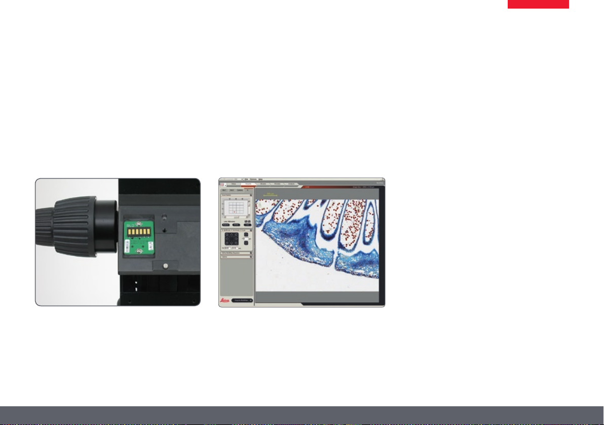
Exact reproducibility of results is an increasingly common demand, particularly in research
and development. The continuous encoding
captures parameters such as the magnification, the illumination, the position of the iris
Leica Application Suite (LAS) evaluates the
transmitted data and can restore the test situation later.
diaphragm and more to the Leica LAS software.
Thus you always know the conditions under
which an image was acquired.
Fewer cables
A large part of the cables have been routed in
the interior of the column. Data are also transferred via the interface between the column,
the optics carrier and the carrier. The direct
result is that you need fewer cables—this not
only makes your workstation neater and more
comfortable, it even makes it appear larger.
Leica M series Manual 15
Page 16
The Modular Design: Everything is Relative
The Leica M series provides maximum flexibility in choosing equipment, thanks primarily to
the modular configuration and the compatibility that Leica has painstakingly maintained for
decades. The optics carriers, eyepieces, bases
and more can be combined in any way you
choose, allowing you to create the microscope
that best suits your needs.
Despite this, you will notice that the controls
and individual components do not differ significantly. Whichever configuration you choose,
you will quickly feel right at home.
Have a special request? Let us know!
Leica Microsystems enjoys an exceptional reputation when it comes to devising customerspecific solutions. If you have a special request
that cannot be met with standard parts, contact
your Leica consultant. We have a solution for
every problem.
Leica M series Manual 16
Page 17

Maximum Compatibility
Leica engineers were careful to ensure that the
new M series—like its predecessors—remains
compatible with existing series. This means
that objectives, bases, tubes and so on can be
reused.
Objectives
All new objectives of the M series are parfocal,
meaning that when used with the objective
nosepiece, they can be replaced while keeping
the specimen in perfect focus.
If you prefer, you can continue to use the previous objective series. In this case, parfocality is
no longer guaranteed.
Tubes
The interface between the optics carrier and the
tube has remained the same, so existing tubes
fit the new M series. The new tubes
for eyepieces with field number 23,
predecessor models were only designed for
field number 21, resulting in a smaller object
field.
Eyepieces
However, the new M-series eyepieces models
have an audible and tangible click to provide
immediate feedback in case of accidental
adjustment.
are designed
while the
Leica M series Manual 17
Page 18
On We Go
If your new Leica microscope has already been
assembled and commissioned by your Leica
consultant, click here to skip through the installation instructions and go directly to the Quick
Start Guide on page 46.
If, on the other hand, you are assembling the
microscope yourself, continue with the "Assembly" chapter, which begins on page 19.
Leica M series Manual 18
Page 19
Assembly
Leica M series Manual 19
Page 20
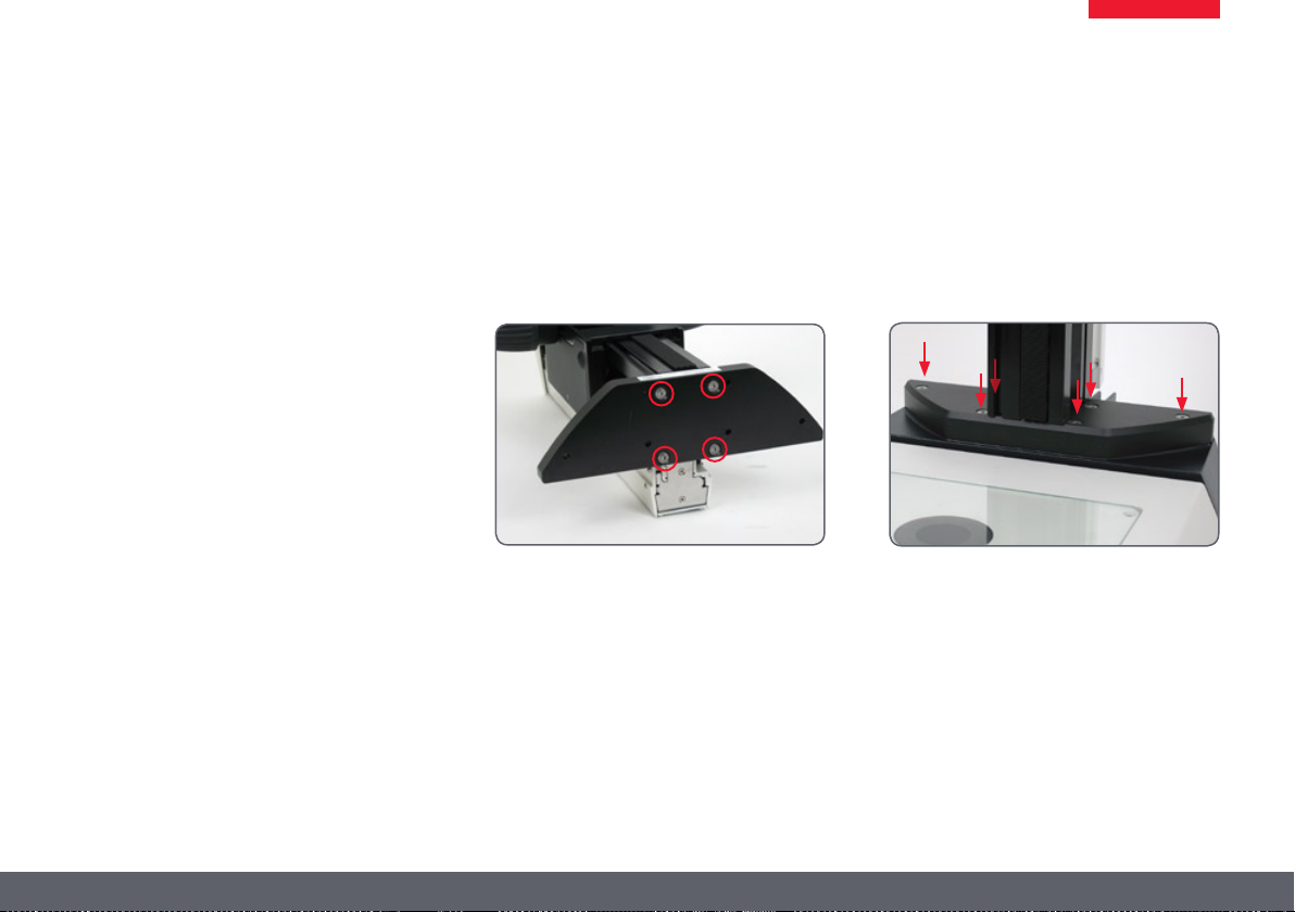
Base and Focusing Column
The first step is to connect the focusing column
of the M series to the corresponding base.
Tools used
Hex socket screwdriver, 3 mm ★
Assembling the column adapter
1. Securely install the column adapter on the
column using the four included screws.
Assembling the focusing drive
2. Securely screw the focusing column to the
base using the six included screws.
Leica M series Manual 20
Page 21
Optics carrier
Tools used
Hex socket screwdriver, 4 mm ★
Assembling the optics carrier
1. Place the optics carrier on the focusing
column so that the screw fit into the thread
provided and the lug fits into the groove.
2. Press the optics carrier backwards to the
focusing column and screw it in place using
your other hand.
Leica M series Manual 21
Page 22
Tube
All intermediate tubes that fit between the
optics carrier and the binocular tube are fitted
in the same manner.
Tools used
No tools required. ★
Preparations
1. Unscrew the positioning screw and remove
the protective cover.
Assembling the tube
2. Push the tube (for example, the inclined
binocular tube) into the dovetail ring and
rotate it slightly in both directions until the
positioning screw meshes with the guide
groove.
3. While holding the tube only slightly, carefully tighten the positioning screw. It
is automatically brought to the correct
position.
Leica M series Manual 22
Page 23
Eyepieces
Tools used
No tools required. ★
Magnification range
You can extend the overall magnification range
using available 10×, 16×, 25× and 40× widefield eyepieces for persons wearing glasses.
Preparation
1. If you want to use an optional graticule,
insert it now (page 62).
2. Remove the plastic tube guard.
Inserting the eyepieces
3. Push the eyepieces into the tubes as far as
they will go and check to ensure that they
fit tightly and accurately.
4. Securely tighten the clamping screws.
Leica M series Manual 23
Page 24
Objective
Tools used
No tools required. ★
Preparation
1. Remove the protective cap on the optics
carrier by turning it.
Attaching the objective
Hold the objective firmly during assem-
bly and disassembly so that it does not
fall onto the stage plate. This applies particularly to the 2× planapochromatic objective,
which is very heavy. Remove all specimens from
the stage plate first.
2. Screw the objective clockwise into the
optics carrier.
Alternative fastening options
If using the objective nosepiece, read the ★
instructions on page 25.
If using the AX carrier, read the instructions ★
on page 27.
Leica M series Manual 24
Page 25
Objective Nosepiece – Assembly
Preparations
Hold the objectives firmly during
assembly and disassembly so that they
do not fall onto the stage plate.
Move the drive housing all the way upwards ★
and remove the optics carrier, if the carrier
has already been installed.
Assembly
1. Remove the transport anchor from the
objective nosepiece.
2. Rotate the moving part by 90° and attach
the objective nosepiece to the drive housing from the front (!). Screw the objective
nosepiece firmly into place.
3. Unscrew the three Phillips screws on the
objective mount of the optics carrier and
remove the intermediate ring.
4. Screw the optics carrier onto the objective
nosepiece.
5. Screw both objectives onto the objective
nosepiece. It makes no difference which
position an objective occupies.
6. Unscrew the locking screws on both sides
of the objective nosepiece.
You can now adjust the parfocality (see instructions on the next page).
Leica M series Manual 25
Page 26
Objective Nosepiece – Adjusting Parfocality
The following procedure only has to be carried
out once. Afterwards, both objectives are parfocal, meaning that the specimen remains in focus
when the objective nosepiece is rotated.
This procedure must be repeated if you replace
either of the two objectives with another.
The following example assumes the combination of the 1× and 2× planapochromats. If
you are using another objective combination,
replace the 2× objective in the description with
the objective with the stronger magnification.
Preparation
Open the iris diaphragm. ★
Set the dioptric correction of the eyepieces ★
to "0".
Adjustment
1. Rotate the 2× objective into the beam path
and set it to the lowest magnification.
2. Focus on the specimen.
3. Rotate the 1× objective into the beam
path.
4. Turn the objective on the thread in both
directions until the specimen appears
sharp.
5. Toggle to the 2× objective.
6. Select the strongest magnification and
refocus until the specimen appears absolutely sharp.
7. Toggle to the 1× objective.
8. Turn the objective on the thread in both
directions until the specimen appears
absolutely sharp.
By means of zooming, check that the behavior
of the objective is parfocal. Repeat the check
with the other objective. If it is not parfocal,
repeat the procedure.
9. Tighten the locking screws.
Leica M series Manual 26
Page 27
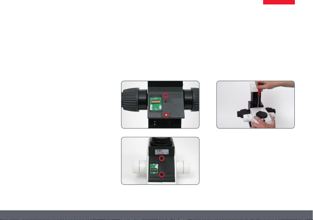
AX Carrier – Preparation
Tools
Hex socket screwdriver, 2.5 mm ★
Preparing the AX carrier
Before the AX carrier is installed, it may first
have to be prepared for the optics carrier to be
used (Leica M125, M205 C or M165 C).
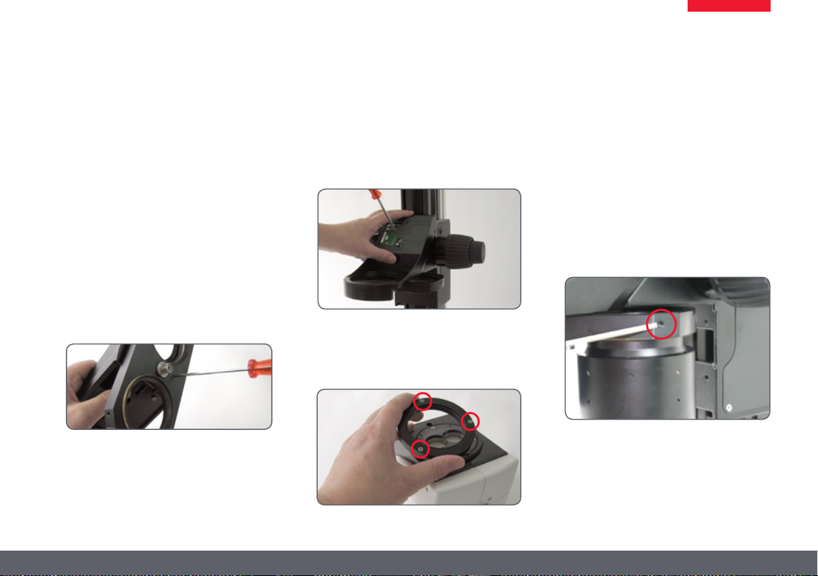
1. Check the switch position.
If the switch position corresponds to the ★
optics carrier used, skip the following steps.
Otherwise, proceed as follows:
2. Unscrew the two screws that hold the
switch in position.
4. Important: push the switch all the way into
the mount while reinserting the screws.
Only this ensures that the switch is positioned correctly.
3. Pull out the switch, rotate it into the desired
position and reinsert it.
Leica M series Manual 27
Page 28
AX Carrier – Assembly
Tools
Hex socket screwdriver, 4 mm ★
Philips screwdriver ★
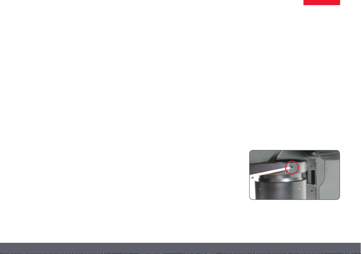
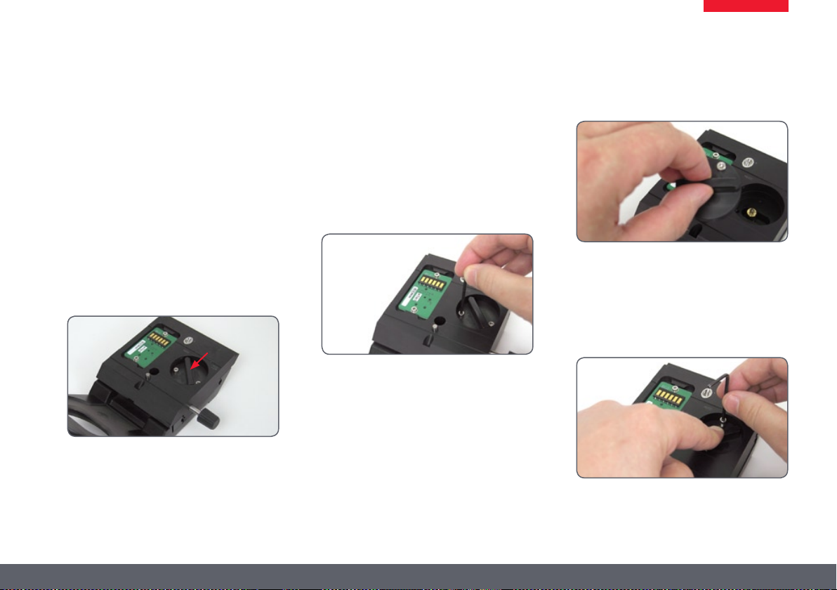
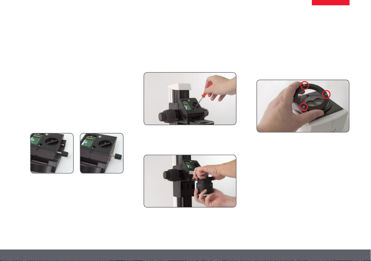
Once the AX carrier has prepared for the corresponding optics carrier, it can be installed.
1. Move the slide of the AX carrier into mid
position.
Wrong Right
2. Install the AX carrier on the focusing
column.
3. Screw the objective to the AX carrier.
4. Unscrew the three holding screws and
remove the adapter ring on the optics
carrier.
5. Install the optics carrier on the AX carrier.
Leica M series Manual 28
Page 29
Transmitted-light Base TL ST
Unpacking the base
The base is delivered with the adapter plate
installed. Make sure the devices are unpacked
on a flat, sufficiently dimensioned, and non-slip
surface.
Focusing drive and column
1. Unscrew the extension plate from the base
using the Allen key provided.
2. Attach your focusing drive column to the
bottom using the 4 Allen screws.
3. Reattach the adapter plate to its original
position using the 6 Allen screws.
Leica M series Manual 29
Page 30
Transmitted-light Base TL BFDF: Before First Use
Removing the transport anchors
Before you can use the transmitted-
light base for the first time, it is absolutely necessary to remove the two transport
anchors as follows.
Anchor of mirror
Anchor of switching slide
Leica M series Manual 30
Page 31

Transmitted-light Base TL BFDF
Standard delivery
The base is delivered with the adapter plate
installed. The selected stage (IsoPro™ crossstage or standard stage 10 447 269), and the
focusing drive will have to be mounted later.
Stage assembly
The TL BFDF transmitted-light base can be
equipped with three different stages.
Leica IsoPro™ manual cross-stage ★
Leica IsoPro™ automatic cross-stage ★
Standard stage 10 447 269 ★
The selected stage is mounted on the base
before commissioning. You can switch between
the stages at any time with just a few hand
movements.
The following paragraph assumes use of the
base without the stage mounted. Disassembly
is performed in reverse order of the following
steps.
Standard stage
1. Take the glass plate from the rectangular
gap in the standard stage.
2. Position the stage on the transmitted-light
base in such way that the four holes align
over those in the base.
3. Attach the stage to the base using the four
Allen screws provided.
4. Insert the glass plate back into the standard
stage.
Leica M series Manual 31
Page 32

TL RC™ / TL RCI™
The base is delivered with the adapter plate
installed. The selected stage (IsoPro™ crossstage or standard stage 10 447 269), and the
focusing drive will have to be mounted later.
Ensure that the instruments are unpacked on a
level, adequately sized, and nonskid underlay.
Stage assembly
The transmitted-light base TL RC™/ RCI™ can
be equipped with three different stages. The
selected stage is mounted on the base before
commissioning. You can switch between the
stages at any time with just a few hand movements.
The following paragraph assumes use of the
base without the stage mounted. Disassembly
is performed in reverse order of the following
steps.
Standard stage
1. Take the glass plate from the rectangular
gap in the standard stage.
2. Position the stage on the transmitted-light
base in such way that the four holes align
over those in the base.
3. Attach the stage to the base using the four
Allen screws provided.
4. Insert the glass plate back into the standard
stage.
Leica M series Manual 32
Page 33

IsoPro™ Manual Cross-stage: Assembly
IsoPro™ Cross-stage
Before the IsoPro™ cross-stage is mounted to
the base, the axis containing the control buttons
is attached either on the left or the right side of
the cross-stage.
If the controls are to be mounted on the lefthand side, the gear rod on the bottom side of
the cross-stage must be unscrewed and reattached in reverse.
1. Take the glass plate from the cross-stage.
2. Turn the cross-stage around and place it
onto a non-slip surface.
3. Change the gear rod from the left to the
right-hand side.
4. Skip the next two steps to mount the
controls.
Before the IsoPro™ cross-stage is mounted to
the base, the axis containing the control buttons
is attached either on the left or the right side of
the cross-stage.
Left or right operation
If the controls are to be mounted on the lefthand side, the gear rod on the bottom side of
the cross-stage must be unscrewed and reattached in reverse.
Leica M series Manual 33
Page 34

IsoPro™ Manual Cross-stage: Assembly (continued)
1. Take the glass plate from the cross-stage
and turn it around.
2. Change the gear rod from the left to the
right-hand side.
Control assembly
1. Take the glass plate from the cross-stage
and turn it around.
2. Attach the axis with the control buttons to
the desired side. The fastener snaps into the
cross-stage magnetically.
4. Attach the axis with the two Allen screws
provided.
5. Attach the cover rail to the cross-stage.
Cross-stage assembly
1. Place the cross-stage on the base.
2. Pull the upper part of the cross-stage carefully toward the user, fastening the lower
part onto the transmitted-light base.
Leica M series Manual 34
Page 35

IsoPro™ Manual Cross-stage: Assembly (continued)
3. Screw the cross-stage evenly onto the three
threaded holes.
4. Push the cross-stage all the way back
towards the column.
5. Reinsert the glass plate back into the standard stage.
Focusing drive and column
1. Unscrew the extension plate from the base
using the Allen key provided.
2. Attach your focusing drive column to the
bottom using the three Allen screws.
3. Reattach the adapter plate to its original
position using the three Allen screws.
Leica M series Manual 35
Page 36

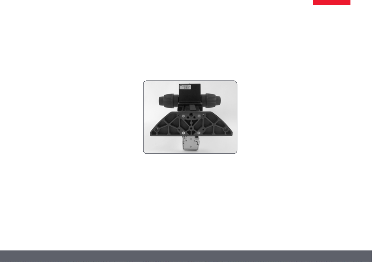
IsoPro™ Motorized Cross-stage: Assembly
Basics
The transmitted light bases of the TL series
(TL BFDF, TL RC™, TL RCI™) are supplied with
an installed extension plate. The selected
stage (IsoPro™ cross-stage or standard stage
10 447 269), and the focusing drive will have to
be mounted later.
The motorized cross-stage is a sensitive precision instrument. During installation, avoid
subjecting the stage to impact or severe vibrations.
1. Unpack the cross-stage from the transport
packaging and position it on the transmitted-light base.
1
2
1 Microscope base
2 Motorized cross-stage
2. Secure the motorized cross-stage to the
base using 3 M4 screws.
3× M4 screws
Leica M series Manual 36
Page 37

IsoPro™ Motorized Cross-stage: Assembly (continued)
3. Remove the two M3 screws and the holder
from the cross-stage.
4. Remove the two M4 screws and the sleeve
from the cross-stage.
5. Remove the four shock-absorbing cartons
from the cross-stage.
After removal, keep all the transport anchors in the plastic bag
for future transport.
Leica M series Manual 37
Page 38

IsoPro™ Motorized Cross-stage: Assembly (continued)
The bases
The TL BFDF, TL RC™ and RCI™ transmitted light
bases can be equipped with three different
stages: standard stage, manual and IsoPro™
automated cross-stage. The selected stage is
mounted on the base before commissioning.
You can switch between the stages at any time
with just a few hand movements.
The following paragraph assumes use of the
base without the stage mounted. Disassembly
is performed in reverse order of the following
steps.
Cross-stage and base
Never move the sledge of the motorized
cross-stage manually in the X direction,
as otherwise the mechanical system will be
damaged!
1. Place the cross-stage on the base.
2. Pull the upper part of the cross-stage care-
fully toward the user, fastening the lower
part onto the transmitted-light base.
3. Screw the cross-stage evenly onto the three
threaded holes.
4. Push the cross-stage all the way back
towards the column.
5. Reinsert the glass plate back into the stan-
dard stage.
Leica M series Manual 38
Page 39

IsoPro™ Motorized Cross-stage: Assembly (continued)
Cross-stage for X-Y Stage Control Module
1. Plug the CTL2 plug of the cross-stage motor
into one of the three available CTL2 interfaces.
2. Plug the CTL2 plug of the Leica PSC controller into another CTL2 interface.
The third CTL2 interface is available for ★
connecting other instruments, such as the
Leica foot switch (10 447 398) or TL RCI™
transmitted light base (10 446 352).
The 15-pin Sub-D interface is intended for ★
use with the Leica SmartMove™ controller
(11 501 197).
3. Plug a power cable into the socket provided
and into a grounded power socket.
As soon as all instruments have been plugged
into the control box and it has been plugged
into the power supply, the cross-stage initializes
and automatically drives to the mid position.
4. Connect the PC and X-Y Stage DCI Module
(with a suitable USB cable).
Leica M series Manual 39
Page 40

Cables: Terminals
The new Leica M-series features extensive
encoding with which various microscope data
and settings can be read out, transferred to the
PC and reproduced later.
The interface to the optics carrier is on the ★
column.
The Terminals The connection to the PC and to other instru-
ments is made using the terminals on the rear
side of the column:
1
3
2
1. 2×CTL2 terminals for auxiliary equipment
such as the ring illuminator, the base and
other accessories from the Leica product
range.
2. Terminal for the 50-watt power supply
provided.
3. USB terminal for the connection to the PC.
Leica M series Manual 40
Page 41

Cables: Cable Duct
The integrated cable duct in the column enables
a neat cable layout around the microscope.
For example, the USB or FireWire cables of the
camera can be stowed in the cable duct.
Feeding the cables
1. Unscrew the three screws on the cable
duct.
2. Remove the cover of the cable duct.
3. Place the cables in the cable duct and screw
the cover on tightly.
Tip: Estimate the length of the cable ends you
will need before screwing on the cover. For
thick cables, it is difficult to change the length
retroactively.
Leica M series Manual 41
Page 42

Cables: Diagram
Alternative installation
Please use the Leica Application
Suite to configure the functions
of the system.
115/230 V
LED5000 RL
LED5000 MCI™
DCI Controlbox
Power/USB
Footswitch 1
(Connect to free CTL2-port on last footswitch.)
Leica M series Manual 42
Footswitch 2...
115/230 V
TL RCI™
Smart Move
PSC
115/230 V
PC USB
Connector from Cross Stage
Page 43

Leica LED5000 MCI™
The Leica LED5000 MCI™ (for "Multi Contrast
Illumination") is installed using two screws. For
optimum accessibility, the optics carrier should
be removed during installation (see page 15.)
Constraints
The Leica LED5000 MCI™ cannot be used
together with the objective nosepiece.
Assembly
1. Hold the LED5000 MCI™ with one
hand and tightly screw the retraining
stirrups on both top holes on the drive housing.
2. Connect the CAN-bus cable to either of the
two sockets. (The flat part of the plug must
be facing downwards.)
3. Plug the other end of the cable into one of
the two "CTL2" sockets on the column.
Leica M series Manual 43
Page 44

Leica LED5000 MCI™: Alternative Assembly
Under certain circumstances, the light source
must not be moved along with the optics
carrier. A typical example is multifocus images
in which the Z-stack changes while the angle
of incidence of the light must remain the same.
For such purposes, the Leica LED5000 MCI™ is
directly fastened to the column.
Installation on the column
1. Pull the retaining stirrup out of the Leica
LED5000 MCI™.
2. Screw the retaining stirrup into the column
at the notch using the single screw. If you
tighten the screw, the retaining stirrup is
automatically moved into the correct position.
3. Push the Leica LED5000 MCI™ onto the
retaining stirrup.
Leica M series Manual 44
Page 45

Leica LED5000 RL
The ring illuminator, the Leica LED5000 RL
("Ring Light"), is installed on the objective using
a single screw. It has been optimized for a working distance between 60 and 70 mm.
Constraints
The Leica LED5000 RL can be used in conjunction with the planapochromat 1× and planapochromat 0.63× objectives. With all other
objectives, the working distance is too low for
adequate illumination.
The ring illuminator cannot be used together
with the objective nosepiece.
Assembly
1. Connect the CAN-bus cable to the
ring illuminator. The flat part of the plug
must be facing upwards.
2. Push the ring illuminator over the
objective as far as it will go and screw it
into place.
3. Plug the other end of the cable into
one of the two "CTL2" sockets on the
column.
For optimum accessibility of the specimen,
the ring illuminator should be installed with
the cable facing backwards. However, it is also
possible to turn the ring illuminator sideways,
for example if simultaneously using the Leica
LED5000 MCI™ system illumination. In this
case, the ring illuminator cannot be connected
directly to the Leica LED5000 MCI™.
Leica M series Manual 45
Page 46

Quick Start Guide
Leica M series Manual 46
Page 47

The Fastest Route to Success
Your Leica stereomicroscope has been delivered in completely assembled
condition by your Leica partner, and naturally you want to get right to
work. Therefore, your next step should be to study the Quick Start Guide,
which outlines the most important steps at a glance.
This manual will then familiarize you with the finer details of your microscope. The following pages contain important, practical information that
makes using it every day easier.
Take time to read it – it's worth it!
The M series Quick Start Guide (included with instrument).
Leica M series Manual 47
Page 48

Overview of an M series Microscope
Click an entry or a position on the microscope to go directly to the corresponding part of the manual.
1 Magnification changer (zoom)
2 Switch click stops on/off
3 Coarse/fine focusing
4 Fastening screw for the binocular tube
(or accessories)
5 Interchangeable objective
6 Adjustable eyepiece tubes
7 Eyepieces for spectacle wearers with dioptric
correction and eyecups
8 Fastening screws for the eyepieces
9 Trinocular tube
10 Built-in iris diaphragm
11
7
8
6
4
10
5
9
2
1
3
Leica M series Manual 48
Page 49

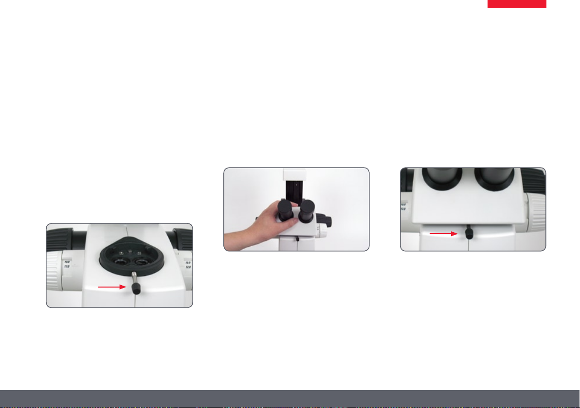
The Correct Interpupillary Distance
The interpupillary distance is correctly set if you
see a single circular image field when looking
at a specimen.
If you are still a novice microscope user, you
may need a short time to become accustomed
to this. Not to worry—after a little while, it will
become automatic.
Reference value
The distance between eye and eyepiece
measures approx. 22 mm for 10/23B wide-field
eyepieces for persons wearing glasses.
Adjusting the Interpupillary Distance
1. Look into the eyepieces.
2. Hold the eyepieces with both hands. Push
the eyepieces together or separate them
until you see a circular image.
3. Slowly approach the eyepieces with your
eyes until you can see the complete image
field without corner cutting.
✗
✓
Leica M series Manual 49
Page 50

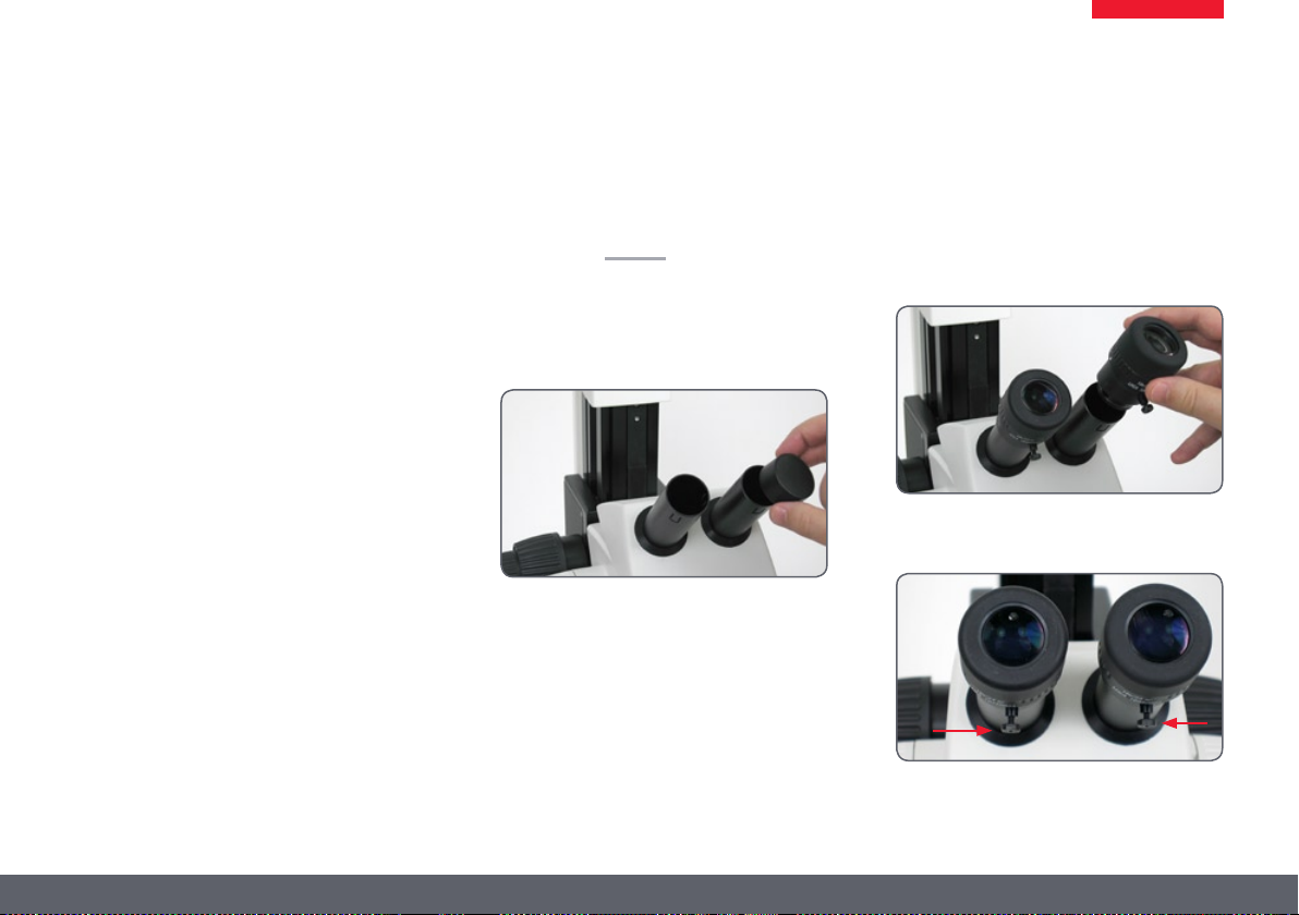
Using the Eyepieces
The eyepieces form the connection between
the tube and the eye of the observer. Simply
push them into the tube and they are ready to
use.
Each eyepiece offers a certain magnification
factor that has a determinative effect on the
total magnification. Furthermore, all Leica
eyepieces can be equipped with practical graticules that enable measuring and quantifying of
specimens.
Dioptric correction
A built-in dioptric correction is available for
eyeglass wearers. For more information, refer
to page 60.
If you do not wear glasses:
1. Hold the eyepiece firmly and rotate the
eyecups forwards counterclockwise.
2. If an eyepiece is equipped with the inte-
grated dioptric correction, turn the value to
the "0" mark.
If you wear glasses:
1. Hold the eyepiece firmly and rotate the
eyecups counterclockwise towards the rear,
as otherwise the viewing distance is too
great.
2. If an eyepiece is equipped with the integrated dioptric correction, turn the value to
the "0" mark.
By the way, one benefit of viewing with
eyeglasses is a drastically lower risk of bacterial transmission (see page 59). The soft material of the eyecup also ensures that your glasses
will not be scratched, even if they contact the
eyepiece.
Leica M series Manual 50
Page 51

Focusing
Focusing raises or lowers the stereomicroscope
using the focusing drive. The specimen detail is
brought into sharp focus as soon as it is in the
focal point of the objective.
The focusing drive can be operated either ★
left- or right-handed.
Focusing
The inner, coarse adjustment is used for ★
covering great distances.
The outer, fine adjustment is used for fine ★
focusing.
Coarse/fine adjustment
The sharpness is adjusted using the coarse/fine
adjustment.
The coarse/fine adjustment carries a
load of up to 15 kg.
The resolution of the coarse/fine adjust- ★
ment is 1 µm.
Leica M series Manual 51
Page 52

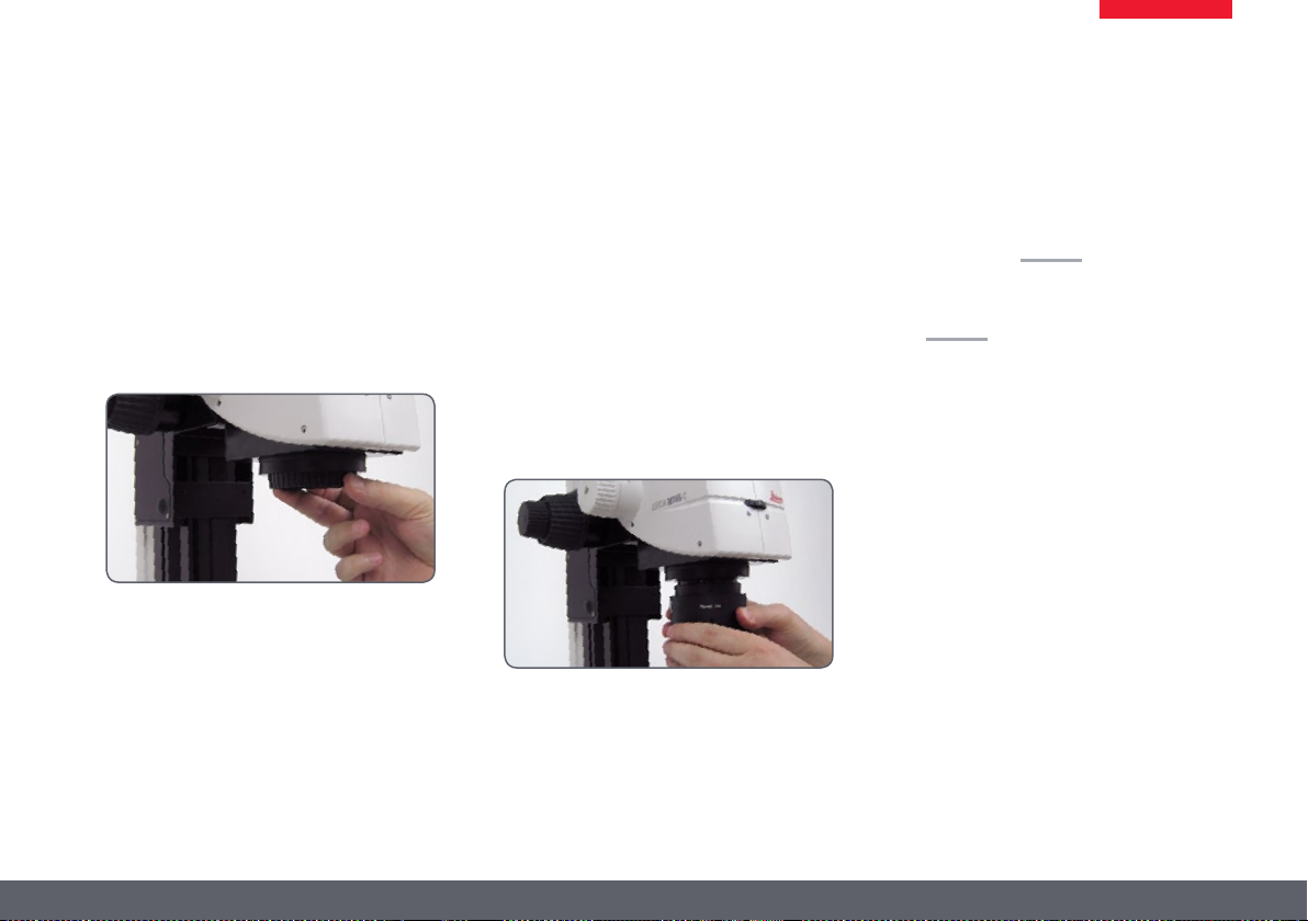
Adjusting the resistance of the focus drive
Adjusting the resistance
Is the focus movement too loose or too tight?
Does the outfit tend to slide downwards? The
resistance can be adjusted individually depending on the equipment weight and personal
preferences as follows:
1. Grip the outer drive knobs with both hands
and turn them towards each other until the
desired resistance is reached during focusing.
Leica M series Manual 52
Page 53

Changing the magnification (zoom)
All M series microscopes have an integrated
zoom. The name indicates the zoom range
covered:
Leica M125 = 16.5:1 ★
Leica M165 C = 16.5:1 ★
Leica M205 C = 20.5:1 ★
The rotary knob for the zoom can be used either
left or right-handed.
Zooming
1. Look into the eyepieces.
2. Focus on the specimen.
3. Rotate the magnification changer until the
desired magnification is configured.
Leica M series Manual 53
Page 54

Ratchet Steps and Magnification Levels
The zoom button can optionally be operated
either with or without ratchet steps. Continuous zoom is possible when the ratchet steps are
disabled, which many users find convenient.
On the other hand, when the ratchet steps are
enabled, photographs, measurement results
etc. can be reproduced more accurately.
Enabling and disabling ratchet steps
1. Push the top button downwards to disable
the ratchet steps.
2. Push the bottom button upwards to enable
the ratchet steps.
Magnifications and
fields of view
The formula on page 112 provide additional
information about the magnifications and field
of view diameters, with consideration given to
the position of the magnification changer and
the eyepiece and objective combination used.
Leica M series Manual 54
Page 55

Parfocality: More Comfort and Convenience for Your Work
All Leica stereomicroscopes are parfocally
matched, meaning that you can view a focused
specimen from the lowest to the highest magnification without having to refocus. There is no
need to readjust the focus to view of specimen
location that is located higher or lower.
Requirements for parfocal work
If you are using an eyepiece with dioptric ★
correction, the procedure differs from this
description. For more information, refer to
page 61.
For the procedure for adjusting the parfo- ★
cality for the objective revolver, refer to
page 26.
Parfocality
1. Enlarge the view to the maximum level.
2. Focus on the specimen.
You are done! Even if you select a smaller working distance, the specimen remains pin-sharp.
The parfocality is maintained until you focus on
another level of the specimen.
Leica M series Manual 55
Page 56

Iris Diaphragm
The iris diaphragm in the optics carrier of your
M series microscope has the same purpose as
those in a camera shutter: it regulates the available light, which changes the depth of field. The
"depth of field" is the area of a specimen that is
brought into sharp focus.
Closing the iris diaphragm
Close the iris diaphragm by turning the ★
knob to the left. The subject appears darker
and the depth of field increases.
Opening the Iris Diaphragm
Open the iris diaphragm by turning the ★
knob to the right. The subject now appears
brighter, but the depth of field decreases.
Leica M series Manual 56
Page 57

Eyepieces
Leica M series Manual 57
Page 58

Magnification Factors of the Eyepieces
An eyepiece not only makes it possible to look passively into the microscope, but also has a critical effect on the maximum magnification. The
magnification factor is between 10x and 40x.
The following eyepieces are available for the M series:
Magnification Dioptric correction Order number
10× ± 5 diopter settings 10 450 023
16× ± 5 diopter settings 10 450 024
25× ± 5 diopter settings 10 450 025
40× ± 5 diopter settings 10 450 026
Leica M series Manual 58
Page 59

Health Notes
Potential sources of infection
Direct contact with eyepieces is a
potential transmission method for
bacterial and viral infections of the eye. The risk
can be kept to a minimum by using individual
eyepieces or detachable eyecups. Eyecups can
be ordered separately. Please contact your
Leica partner.
Separate eyecups are an effective way of
preventing infections.
Leica M series Manual 59
Page 60

Dioptric correction
All Leica eyepieces are also available with
built-in dioptric correction, allowing the microscope to be used without glasses even by those
with vision problems. The correction comprises
±5 diopter settings.
Using the Dioptric Correction
1. Set the dioptric correction of both eyepieces
to the mid position ("0" diopter settings.
2. While wearing your glasses, look through
the eyepieces and focus on the specimen.
3. Rotate both eyepieces to the maximum
value of "+5".
4. Hold one eye closed and rotate the other
eyepiece in "-" direction until the specimen
appears sharp.
5. Then, open the other eye and correct the
diopter settings until the image is uniformly
sharp.
Note that when using dioptric correction,
the advantage of parfocality is lost—thus
you have to manually refocus each time you
change the zoom level. To also use parfocality
with dioptric correction, refer to the instructions on page 61.
Leica M series Manual 60
Page 61

Dioptric Correction and Parfocality
Leica stereomicroscopes are parfocally matched.
The prerequisite for this is the correct setting of
the diopters and the parfocality. The following
adjustments only have to be carried out once
by each user.
Preparations
Move the lever of the video/phototube to ★
the "observation" position and open the
diaphragm.
If you are using the microscope carrier AX, ★
set it to stereoscopic observation.
Adjusting
1. Set the dioptric correction for both
eyepieces to "0".
2. Select the lowest magnification and focus
on a flat specimen.
3. Select the highest magnification and readjust the sharpness.
4. Select the lowest magnification again, but
do not look into the eyepieces.
6. Rotate the eyepieces counterclockwise in
the "+" direction as far as they will go (+5
diopter settings).
7. Look into the eyepieces.
8. Slowly rotate each eyepiece individually
in the "–" direction until each eye sees the
object sharply imaged.
9. Select the highest magnification and refocus if necessary.
Now, if you adjust the magnification from the
lowest to the highest level, the specimen is
always brought into sharp focus. If not, repeat
the process.
Leica M series Manual 61
Page 62

Graticules
Use
Graticules make length measurements and
counting easier, particularly for workstations
that are not equipped with a digital camera and
LAS software.
The graticules for length measurements and
numbering are fitted in mounts and are inserted
into the eyepieces.
1. Screw the insert off of the eyepiece.
2. Clamp the graticule on the insert, applying
moderate pressure. Ensure that the graticule fits tightly.
3. Screw the insert and graticule firmly into
place and replace the eyepiece in the tube.
4. You can now align the graticule by rotating
the eyepiece in the tube and then tightening it using the clamping screw.
Use with the AX carrier
If possible, measure with the micro-
scope carrier AX in vertical position. The
measurements are more accurate without the
convergence angle in the stereoscopic image.
Leica M series Manual 62
Page 63
Photography & Video
Leica M series Manual 63
Page 64

Photography & Video
For most microscope users, digital documentation has become an invaluable part of their
work. Research results can be presented in an
attractive manner; measurements on the digital image provide clarity and, in conjunction
with the motorized IsoPro™ cross-stage, even
images of large specimens can be captured
step by step and automatically joined to create
a new complete image.
Adapter
If camera control using the Leica Application
Suite is not required, conventional mirror reflex
and rangefinder cameras from third-party
manufacturers can be used. For this purpose,
Leica Microsystems offers a variety of adapters
that can be used together with the 50% and
100% trinocular tubes.
Leica DFC cameras
However, if you require absolute control
over the camera and need the capability for
measurement, evaluation and more in addition
to photography, the digital Leica DFC cameras
are exactly right for you. Together with the
Leica Application Suite, they provide virtually
limitless freedom of use. For additional information about Leica cameras, refer to the camera's
documentation.
Leica Application Suite
The "Leica Application Suite", or "LAS" for
short, is, as it were, the digital extension of the
Leica M series microscopes. In addition to
capturing images, it lets you control the microscope, illuminator, stages, cameras and more.
For additional information, refer to the LAS
online help.
Leica M series Manual 64
Page 65

Photo tubes and C-mounts
Application
All Leica DFC cameras are equipped with a
standardized C-mount interface. In turn, the
C-mount adapter for the respective trinocular
tube is connected to this interface. This adapter
creates a solid mechanical connection between
the microscope and camera and ensures optimum rendering of the microscopic image on
the image sensor of the camera.
Usually, the ideal is for the digital camera to
capture as much of the field of vision as possible, while excluding as much of the black edge
of the field of vision as possible. To do so, the
magnification factor of the C-mount adapter
must match the image format of the sensor as
closely as possible (see table).
If there is unwanted shading at the corners even
with a compatible C-mount adapter installed, it
can be corrected using the "Shading function"
of the camera software.
Alternatively, you can also use a C-mount
adapter with higher magnification. This primarily avoids the critical border area of the field of
vision and concentrates on the center of the
field of vision.
Camera optimal
(large
image field)
DFC290 0.5× 0.63×
DFC420 0.5× 0.63×
DFC490 0.63× 0.8×
DFC500 0.63× 0.8×
suitable
(smaller
image field)
Cameras from third-party suppliers
In addition to Leica DFC cameras with the standardized C-mount interfaces, you can connect
third-party cameras to the microscope using
a T2 bayonet adapter. To do so, instead of the
C-mount adapter, simply use the corresponding SLR adapter with T2 connection. However,
these third-party cameras are not integrated
into the Leica Application Suite and have to
be operated using the corresponding software
from the camera manufacturer.
The Leica digital cameras are detailed in a separate user manual along with instructions for
their assembly and use.
Leica M series Manual 65
Page 66

Trinocular video/phototube 50%
Use
With its third beam path, the trinocular video/
phototube 50% enables you to simultaneously
view and photograph a specimen. The available
light is divided as follows:
50% is available for the two eyepieces. ★
50% of the light is diverted to the video/ ★
photo beam path.
Assembly
Fasten the "trinocular tube 50%" to the optics
carrier instead of the binocular observation
tube (refer to page 22).
Leica M series Manual 66
Page 67

Trinocular video/phototube 100%
Use
With its third beam path, the trinocular video/
phototube 100% enables you to either view or
photograph a specimen. This means that 100%
of the light is available to one or the other beam
path. The other beam path remains opaque or
black.
Assembly
Fasten the "trinocular tube 100%" to the optics
carrier instead of the binocular observation
tube (refer to page 22).
Switchover
Turn the controller on the right side of the ★
tube into the horizontal position in order to
guide all available light into the eyepieces.
You can now observe the specimen.
Turn the controller on the right side of the ★
tube into the vertical position in order to
guide all available light into the camera.
You can now photograph the specimen.
Leica M series Manual 67
Page 68

Microscope Carrier
Leica M series Manual 68
Page 69

The Microscope Carrier AX
Users who intend to do a great deal of photography, take measurements or work with polarization should select the microscope carrier AX
for stereoscopic/axial observation. The parallaxfree imaging by means of a perpendicular beam
path leads to results without parallax error.
Compatibility
The planachromatic and planapochromatic
objectives fit into the thread in the microscope
carrier AX for the Leica M125, Leica 165 C and the
Leica M205 C.
Stereoscopic viewing
A stereoscopic view is required for examining
spatial objects. For this purpose, the microscope carrier AX must be brought to its home
position.
1. Unscrew the clamping screw.
2. Push the microscope into the home position (mid position) to obtain a spatial view
and tighten the clamping screw.
Leica M series Manual 69
Page 70

The Microscope Carrier AX (continued)
Parallax-free images
The parallax-free imaging produces more
precise results in photography, measuring and
polarization.
1. Unscrew the clamping screw.
2. Push the microscope towards the left as
far as it will go and tighten the clamping
screw.
The objective is now located directly beneath
either the left or the right beam path.
Coaxial light and the Leica M205 C
When using coaxial incident light together with
the Leica M205 C, unscrew the clamping screw
and press the optics carrier towards the right
(caution: the movement is only 2 mm). This
provides uniform light intensity in both beam
paths.
Leica M series Manual 70
Page 71

The Objective Nosepiece
Use
The objective nosepiece enables you to switch
between two objectives using just one hand
movement, for example between a 1× and a 2×
planapochromat.
Parfocal work
With the new M series objectives, the parfocality is maintained even when objectives are
changed, meaning that the specimen remains
in sharp focus during the change.
Older Leica objectives can continue to be
used, but without parfocality during the
objective change.
Technical constraints
The objective nosepiece cannot be
used together with the LED5000 MCI™
system illumination, as the objective nosepiece
can no longer be rotated.
Leica M series Manual 71
Page 72

Objectives and optical accessories
Leica M series Manual 72
Page 73

The Different Types of Objectives
To meet the various requirements regarding
imaging properties, there is a choice of highquality interchangeable planachromatic and
planapochromatic objectives and also lowerpriced interchangeable achromatic objectives.
Achromatic objectives are particularly ★
suited for specimens with high-contrast
structures.
Flat-field (planachromatic) objectives are ★
particularly well suited for studying flat
objects such as wafers and thin sections.
With planapochromatic objectives, the ★
finest structures are visible with high
contrast. The sophisticated apochromatic
correction allows these objectives to attain
the highest color brilliance and fidelity.
Achromatic objectives
The 0.32×, 0.5×, 0.63×, 0.8×, 1×, 1.5×, 2×
achromatic objectives offer countless variants
for selecting the object field diameter, magnification ranges and working distances (see
page 112).
Planachromatic objective 1×
For the highest requirements for overall image
quality, we recommend equipping the microscope with the 1× plan (flat-field) objective,
which returns sharp, contrast-rich object fields.
Achromatic objectives with a long focal
length:
For special applications achromatic objectives
with long working distances and focal lengths
of f=100 mm to 400 mm are available.
Leica M series Manual 73
Page 74
Bases
Leica M series Manual 74
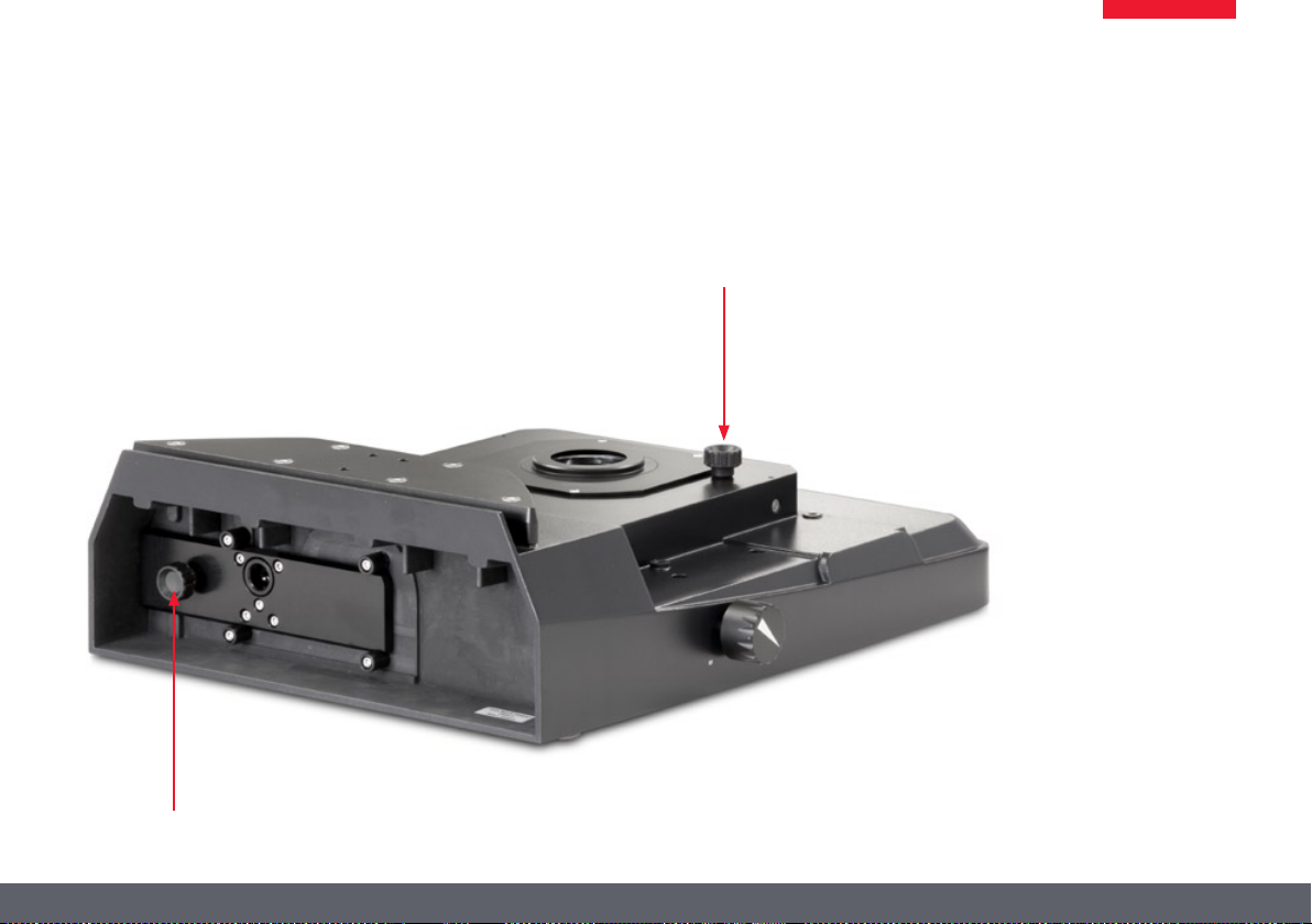
Page 75

Transmitted-light Base TL ST: Controls
1
2
3
4
1 Adapter plate for easy assembly of focusing
drives
2 Removable glass plate
3 Controller for light intensity
4 Adjustment for deflection mirror
Extension plate of the Transmitted-light Base TL ST
1 2 3
Rear side of the transmitted-light base TL ST
1 Screws for changing the halogen lamp
2 Power connection socket
3 Power switch
Leica M series Manual 75
Page 76

Transmitted-light Base TL ST: Operation
Light intensity control
The left control adjusts the intensity of the
12 V/20 W halogen illumination.
1. Switch on the illumination of the base at
the power switch.
3. Focus on the specimen.
3. Set the illumination to the desired intensity
using the left control.
Transmitted-light control
The transmitted-light base TL BFDF has a slider
that automatically moves the deflection mirror
in the base when moved. The mirror is kept in
the correct position at all times and permits
smooth changeover between bright field and
opaque transmitted light.
Bright field
Bright field is suitable for examining translucent objects featuring contrasting structures.
The object is directly illuminated from below
and is seen in its natural colors against a bright
background.
Move the slider backwards until the desired ★
effect is achieved.
Inclined transmitted light
Transmitted light that traverses the object
obliquely will produce effects advantageous for
observing semitransparent, opaque objects.
Slowly pull the slider towards yourself until ★
the desired effect is achieved.
Leica M series Manual 76
Page 77

Transmitted-light Base TL ST: Lamp Replacement
Changing the Halogen Lamp
Before you change the lamp, it is abso-
lutely necessary to unplug the power
plug from the base to prevent the risk of electric shock!
The halogen lamp becomes very hot
during operation. Therefore, to avoid
being burned, let the base cool off for approx.
10 minutes after switching it off!
Do not touch new halogen lamps with
your bare fingers—this drastically
reduces the service life of the lamp!
Changing bulbs
1. Unscrew the two screws on the cooling unit
and pull the cooling unit out, along with
the lamp.
2. Carefully pull out the lamp and mount by
pulling them upwards.
3. Disconnect the lamp from the mount.
4. Insert the new lamp into the mount and
reinsert the lamp holder.
Precautionary measures
When inserting the lamp, ensure that
the cables are inside the two metal
clamps. This prevents the cables from getting
caught during insertion.
Leica M series Manual 77
Page 78

Transmitted-light Base TL BFDF: Controls
1
2
3
1 Adapter plate for easy assembly of focusing
drives
2 Standard stage 10 447 269
3 Button to toggle between bright field and
dark field
Extension plate of the Transmitted-light Base TL BFDF
Adapter at the focusing drive
Connector for cold light sources
Button to toggle between bright field/ dark field
Leica M series Manual 78
(light conductor active f = 10 mm,
end tube f = 13 mm)
Page 79

Transmitted-light Base TL BFDF: Operation
Light intensity control
Please observe the user manual—in
particular, all safety regulations—from
the manufacturers of the light guide and cold
light source.
Switch on the cold light source according to ★
the manufacturer's user manual and adjust
the brightness.
Transmitted-light control
The TL BFDF transmitted-light base has a potentiometer that switches the light from "bright
field" to "dark field".
Bright field
Bright field is suitable for examining translucent objects featuring contrasting structures.
The object is directly illuminated from below
and is seen in its natural colors against a bright
background.
Turn the control as far as it will go towards ★
"BF" ("bright field").
Fingertip with bright field illumination Identical subject with dark field illumination
Dark field
In dark-field illumination, a ring illuminator is
used in such a way that the direct light
does not reach the objective without a specimen. Only the structure of semitransparent,
opaque objects disperses the light, making the
object visible against a dark background.
Turn the control as far as it will go towards ★
"DF" ("dark field").
Leica M series Manual 79
Page 80

TL RC™ / TL RCI™: Controls
1
2
3
4
5
6
7
1 Heat sink of the integrated halogen illumina-
tion (only TL RCI™)
2 Extension plate for focusing drives
3 Standard stage 10 447 269
4 Filter holder
5 Control of top and bottom flaps of the
Rottermann Contrast™
6 Button for mirror and horizontal movement
of the mirror
7 Transmitted-light base
Vertical column - transmitted-light base adapter
plate
1
2
3 4 5 6
1 Power switch
2 Power connection socket
3 USB socket, type B
4 USB socket, type A
5 2× CAN bus
6 Screws for changing the halogen lamp
Leica M series Manual 80
Page 81

TL RCI™: The Deflection Mirror
1
Inverted world?
Depending on the properties of the specimen
(refractive index of the environment) and the
perception of the viewer, it is possible that
the switches described below for positive and
inverted relief contrast are to be operated in
reverse. This means that the lower switch, rather
than of the upper switch, controls inverted relief
contrast and vice-versa.
Tilted mirror
The built-in mirror features one flat and one
concave side and can be rotated and moved.
The concave side has been specially designed
for the optical requirements of objectives with a
high numerical aperture. The black rotary knob
on the left side of the transmitted-light base
can be used to rotate the built-in path-folding
mirror and move it forwards/back.
The concave cutout on the handle indicates the
concave side of the mirror, allowing intuitive
operation at any time without eye contact.
The angle of light incidence in the specimen
plane changes depending on the tilt and position of the mirror. As a result, switching between
transmitted light bright field, oblique illumination and dark field-like illumination is possible.
Functions of the rotary knob
The rotary knob (1) fulfills the following tasks:
Turning the deflection mirror from the flat ★
to the concave side.
Slight tilting to guide the light beam ★
through the specimen plane at a steeper or
flatter angle
Moving the deflection mirror (forwards/ ★
back)
Leica M series Manual 81
Page 82

TL RCI™: Color Intensity and Temperature
1 2
1 Potentiometer for controlling the CCIC™
(Constant Color Intensity Control) illumina-
tion intensity
2 Potentiometer for controlling the IsoCol™
color temperature
The transmitted-light base TL RCI™ has two
electronic potentiometers that control the color
intensity (1) and color temperature (2).
The controller for the color temperature simultaneously serves as an electronic shutter:
To interrupt your work, click the potentio- ★
meter (2).
Click again to switch on the illumination. ★
The electronics return to the previously
configured settings.
Using a USB mouse (only TL RCI™)
The Leica USB mouse controls the CCIC™ and
dimming function of the TL RCI™ base. Connect
the mouse to the corresponding USB port of
the base.
The scroll wheel of the mouse is occupied ★
by default with the CCIC™ control system
and is used to control the illumination
intensity.
To switch the illumination on or off, briefly ★
click the scroll wheel.
To enter or exit dimming mode, click and ★
hold down the scroll wheel for longer than
2 seconds.
Leica M series Manual 82
Page 83

TL RC™ / TL RCI™: Operation
Setting the relief contrast
The two switches on the left side of the transmitted-light base TL RC™/TL RCI™ activate two
built-in flaps. The outer switch (1) controls the
inverted relief contrast, and the inner switch (2)
adjusts the positive relief contrast.
1 2 3
1 Switch for adjusting the inverted relief
contrast
2 Switch for adjusting the positive relief
contrast
3 Deflection mirror
Depending on the flap position, a part of
the opening of the built-in Fresnel lenses are
covered, which results in the different contrast
effects. Phase structures typically act as spatial,
relief-type images—in the positive relief
contrast like hills, in the inverted relief contrast
like valleys.
Increased contrast without relief is attained
if both diaphragms are set to 45°. A gap-like
illuminated area is created. By tilting the deflection mirror slightly, you can move the gap over
the entire field of view and quickly toggle
between positive and negative relief images.
The dynamic effect makes it easy to distinguish
phase structures from amplitude structures.
Leica M series Manual 83
Page 84

TL RCI™: Methods in Transmitted Light
Vertical bright-field illumination
Suitable for stained amplitude specimens with
sufficient contrast.
The light beams are deflected vertically through
the specimen. This results in an accurate bright
field with maximum brightness.
Inclined transmitted light
Suitable for semitransparent, opaque specimens such as foraminifera and fish eggs. Move
the deflection mirror until the desired data are
visible.
Single-sided dark field
Suitable for fixed specimens and fine structures.
The flatter the angle at which the light beams
are deflected into the specimen plane, the
darker the substrate appears. A dark field-like
transmitted light is created. Outlines, fine edges
and structures are bright, in contrast with the
dark background, through diffraction of the
light beams on the dark background.
Leica M series Manual 84
Page 85

TL RCI™: Relief Images
Starting position
1. Push the deflection mirror all the way back
towards the column.
2. Turn the deflection mirror into the notch
position at an angle of 45°.
Positive relief contrast
Suitable for semitransparent and transparent
specimens. The phase structures look like hills.
The effect can be strengthened or weakened by
gently tilting the deflection mirror.
Negative relief contrast
Suitable for semitransparent and transparent
specimens. These settings result in a negative relief contrast. Phase structures look like
valleys.
The effect can be strengthened or weakened by
gently tilting the deflection mirror.
Leica M series Manual 85
Page 86

TL RCI™: Relief Images (continued)
Dynamic relief contrast
Suitable for semitransparent and transparent
specimens.
By tilting the deflection mirror slightly, you can
move the gaps over the entire field of view and
quickly toggle between positive and negative
relief images. The dynamic effect makes it easy
to distinguish phase structures from amplitude
structures.
Constraints
The relief methods provide good results from
mid-zoom to high magnifications and with 1×,
1.6× and 2× magnifications. In the lower zoom
half and with weaker specimens, the object
field may not be uniformly illuminated.
We recommend using the transmitted-light
base with 1× or higher objectives, and not
objectives with a long focal length.
Leica M series Manual 86
Page 87

Using Filters
Filters for TL RC™ and TL RCI™
The transmitted-light bases TL RC™ and
TL RCI™ can be equipped with up to three
filters—available as accessories—simultaneously. By customer request, the filters are also
available as one-off items.
1. Switch off the light source or click (TL RCI™)
the button for the shutter.
2. Take the empty filter from an available filter
slot in the filter holder.
3. Insert the desired filter.
4. Switch the light source back on.
Daylight filter for TL ST
A daylight filter is also available for the
transmitted-light Base TL ST.
Leica M series Manual 87
Page 88

IsoPro™ (Non-motorized): Controls
Operating the cross-stage IsoPro™
1. To move the stage in X direction, rotate the
outer knob.
2. To move the stage in Y direction, rotate the
inner control ring.
1 2
Leica M series Manual 88
Page 89

IsoPro™ (Motorized): Controls
IsoPro X-Y Stage DCI module Leica PSC Controller
1 2
1 Motorized cross-stage Leica IsoPro
2 Housing with motorization
1
2
3
1 2 3 4
1 Sub-D interface for Leica SmartMove™
2 3 CTL2 interfaces
™
3 USB interface (type B)
4 Socket for grounded power cable
1 Quick control/memory function
2 Fine control in X direction
3 Fine control in Y direction
Leica M series Manual 89
Page 90

System Illumination
Leica M series Manual 90
Page 91

Leica LED5000 MCI™
Use
The Leica LED5000 MCI™ (for "Multi Contrast
Illumination") is a universal high-output illuminator. Three groups of 3 LEDs each can be
arranged as desired around the specimen. The
targeted control of the LEDs enables various
illumination scenarios to be implemented.
Preparation
Hold the MCI with both hands and pull it downwards until the illuminator clicks into place on
the bottom end of the guide rods.
In this position, you always have the same
contrast with identical illumination. This guarantees the reproducibility of an experiment.
Installed too high
Optimum height
Contact with the base
If the optics carriers are accidentally
lowered too far, contact between the
base and MCI may result. A safety mechanism
in the linkage ensures that in this case, the MCI
is automatically pushed upwards to prevent the
possibility of damage.
Be sure not to place any specimens directly ★
beneath the MCI.
After the optics carrier is lifted, put the MCI ★
back into the original position.
Leica M series Manual 91
Page 92

Leica LED5000 MCI™ (continued)
Using the keyboard
Use the ★ key to switch the illumination on
or off.
Use the "+" and "–" keys to adjust the ★
brightness in 10 increments. Touch either
of the two buttons to adjust the intensity in
small increments. Hold a key to change the
intensity more quickly.
Maximum brightness
Maximum contrast
The illumination scenarios
Use the " " and " " keys to toggle between the
illumination scenarios shown below.
Maximum brightness
For temperature reasons its is not possible to
switch on all nine LEDs simultaneously. Therefore, to provide bright overall illumination, the
top two rows are activated. The bottom row
primarily provides contrast.
Point illumination
from the rear
Point illumination
from the left
The Leica LED5000 MCI™ can also be controlled
by the LAS (Leica Application Suite) software.
Point illumination
from the right
Leica M series Manual 92
Page 93

Leica LED5000 RL
Use
The Leica LED5000 RL ("Ring Light") generates
a very bright and homogenous incident light.
It has a diameter of 80 mm and illuminates the
specimen with 48 LEDs that can be switched on
and off completely or in various combinations.
It is controlled using either the integrated or via
the Leica Application Suite (LAS).
LAS enables you to create fully reproducible
illumination scenarios and automatically toggle
between them. For additional information, refer
to the LAS online help.
Using the keyboard
Use the ★ key to switch the illumination on
or off.
Use the "+" and "–" keys to adjust the ★
brightness in 10 increments. Touch either
of the two buttons to adjust the intensity in
small increments. Hold a key to change the
intensity more quickly.
The illumination scenarios
Use the " " and " " keys to toggle between the
illumination scenarios shown below.
Constraint
The Leica LED5000 RL has been designed for
use with the 1.0× and 0.63× objectives. For the
1.6× and 2.0×, conventional ring illuminators
from the Leica illuminator product range are
available.
Leica M series Manual 93
Page 94

Accessories
Leica M series Manual 94
Page 95
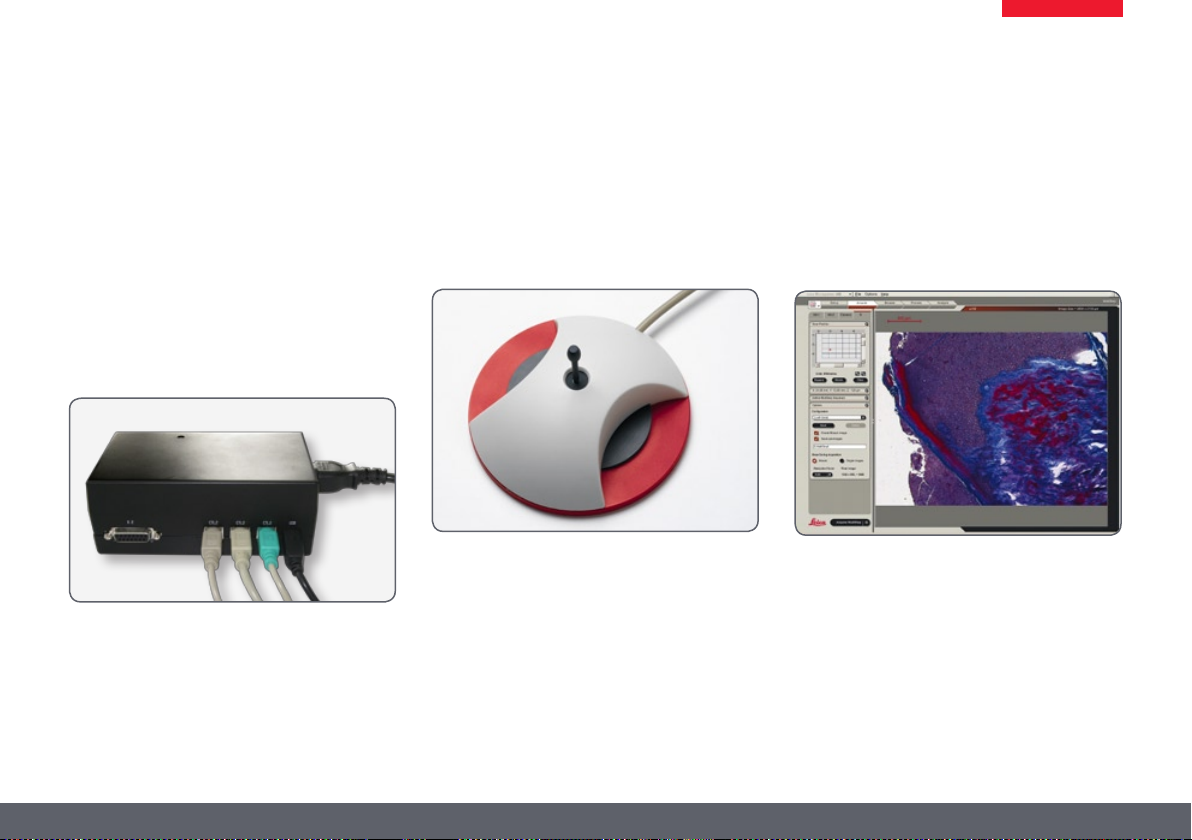
Leica PSC Controller
Use
The Leica PSC controller gives you precision
control of the Leica IsoPro™ motorized crossstage.
Connection
Connect the Leica PSC controller and the Leica
IsoPro™ motorized cross-stage.
Passing over the specimen quickly
Move the joystick in any desired direction ★
(including diagonally) to quickly control
the cross-stage.
Fine control of the cross-stage
The motorized Leica IsoPro™ cross-stage offers
an accuracy of up to 0.25µm. To move to a position with maximum accuracy, use the left and
right knobs on the joystick.
Control by LAS
The instructions for controlling the
Leica IsoPro™ using the Leica Application Suite
are provided in the software's help file.
Leica M series Manual 95
Page 96

Dimensional Drawings
Leica M series Manual 96
Page 97

Leica M125 / M165 C
292
217
120 120
24
455
292
217
120 120
277
24
400
455
Leica M125 / M165 C with incident light base and new focusing column
(dimensions in mm)
Leica M series Manual 97
Page 98

356
292
217
85
154
356
154
217
106 431
537
340
430
85
154
356
154
Leica M125 / M165 C (continued)
Leica M125 / M165 C with transmitted-light base TL ST and manual focus
(dimensions in mm)
Leica M series Manual 98
Page 99

385
292
217
385
154
95
154
116 431
547
292
217
154
340
390
440
95
154
Leica M125 / M165 C (continued)
Leica M125 / M165 C with transmitted-light stand TL RC™ and manual focus
(dimensions in mm)
Leica M series Manual 99
Page 100

497
292
217
497
292
217
187154
max. 370
95
116 431
547
497
187154
max. 370
X = +-75 mm
95
300
249
Y = +-50 mm
Leica M125 / M165 C (continued)
Leica M125 / M165 C with transmitted-light stand TL RC™, manual cross-stage Leica IsoPro™ and manual focus
(dimensions in mm)
Leica M series Manual 100
 Loading...