

Page 1
"
#
DISTO TMclassic
3
User Manual
Page 2

Congratulations on your purchase
of a DISTO.
This User Manual contains
important safety instructions
Instructions") as well as instructions on use
of the instrument.
Read carefully through the User Manual
before you switch on the instrument.
(see section "Safety
Product identification
The identification label for your product is
fitted on the back. The serial number is in
the battery compartment. Enter model and
serial number in your User Manual, and
always refer to this information when you
need to contact your agency or service
centre.
Model: DISTO...........................
Serial no.: ................................
2
Page 3
DISTO classic
Hand-held laser meter
Symbols Used
The symbols used in this User Manual have
the following meanings:
DANGER:
Indicates an imminently hazardous
situation which, if not avoided, will
result in death or serious injury.
WARNING:
Indicates a potentially hazardous
situation or an unintended use
which, if not avoided, could result in
death or serious injury.
CAUTION:
Indicates a potentially hazardous
situation or an unintended use
which, if not avoided, may result in
minor injury and/or in appreciable
material, financial and environmental damage.
Important paragraphs which must
be adhered to in practice as they
enable the product to be used in a
technically correct and efficient
manner.
3
Page 4
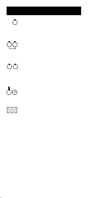
Symbols Used
Press a key briefly
(press/release!)
Press two keys simultaneously
"Double-Click"
(Press the same key twice)
Press for a certain period
Display, e.g. "Set"
4
Page 5

Contents
Open Instrument ...................................... 8
Insert Batteries .......................................1 0
Display..................................................... 12
Keypad.....................................................13
ON Key and Measurement Key .........14
Measuring ..........................................14
Continuous measurement (Tracking). 15
Laser in continuous operation ............. 15
Plus/Minus Key...................................16
Quick switching off ............................. 16
In roll mode.........................................16
Partial heights, chain values ...............16
Multiplication Key ..............................17
Area ...................................................17
Volume ............................................... 17
Time delay release .............................18
Equal Key............................................19
Doubling a measured value ................19
Setting Key ......................................... 20
Settings in roll mode ...........................20
Setting reference only for one
measurement ..................................... 21
Set desired reference
to "Permanent" ................................... 22
Measure with additional tolerance ......23
Unit - metre / feet / feet inch...............24
”Beep“ during operation ...................... 25
Resetting ............................................26
5
Page 6

Contents
Function Key ..................................... 27
Recall last measured value (stack)..... 27
Saving a constant (Fnc 1)................... 28
Recalling the constant ........................ 28
Continuous measurement (Tracking)
Maximum (Fnc 2) ............................... 29
Continuous measurement (Tracking)
Minimum (Fnc 3) ................................ 30
Pythagoras, height measurement
(Fnc 4)................................................ 31
User Information ..................................... 34
Range ..................................................34
Rough Surfaces .................................34
Transparent Surfaces ........................ 35
Wet, Smooth or High-Gloss Surfaces35
Illumination ......................................... 35
Environment .......................................36
Free-handed aiming ...........................36
Inclined, Round Surfaces .................. 37
In the field ........................................... 37
Accessories ........................................38
T elescopic viewer (667478) ................38
Wrist strap (667491) ...........................39
Shoulder strap (563 879) ....................39
Carrying pouch (667 169) ...................39
Level (667 158)...................................39
T arget plate (563875)..........................40
Holster (667489)................................. 40
Software .............................................40
6
Page 7

Contents
Safety Instructions ................................. 41
Use of the Instrument ........................ 41
Permitted use .....................................41
Prohibited uses...................................41
Limits to use .......................................42
Areas of Responsibility .....................43
Hazards in Use ................................... 44
Laser Classification ........................... 47
Labelling ............................................. 48
DISTO with Telescopic Viewfinder....50
Electromagnetic Compatibility
(EMC) .................................................. 51
Care and Storage ...................................54
Care ..................................................... 54
Storage ............................................... 54
Transport ............................................ 55
Despatch ............................................55
Message Codes ...................................... 56
Technical Data ........................................ 57
Remarks on Measuring Accuracy........ 5 8
Set Mark for Viewfinder .........................60
Accuracy Tests.......................................61
7
Page 8
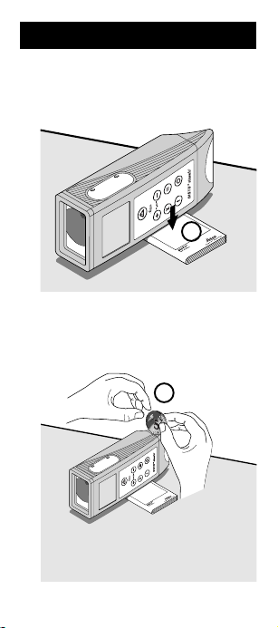
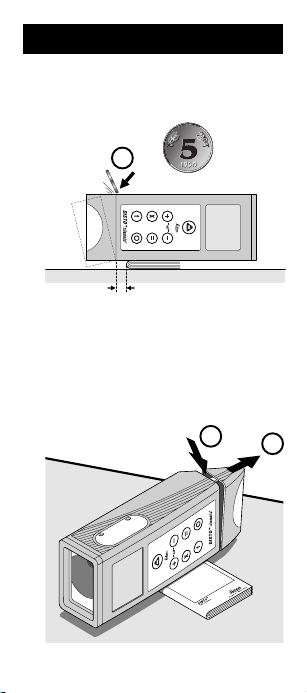
Open Instrument
1. Lay the DISTO onto the User Manual,
as shown below.
1.
2. Hold a large coin between both thumbs.
2.
8
Page 9
Open Instrument
3. Press coin downwards at an angle
against the last notch.
3.
4. By pressing downwards at an angle and
to the front simultaneously, the battery
compartment can be easily opened.
3.
4.
9
Page 10
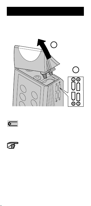
Insert Batteries
5. Remove end cover.
6. Replace batteries.
If battery voltage is too low the
battery symbol appears on the
display. Fit new batteries.
Always replace the complete
battery set!
- Do not use old and new
batteries together.
- Do not use batteries from
different manufacturers or
batteries of different types.
- For type of battery, refer to
Technical Data.
5.
6.
10
Page 11
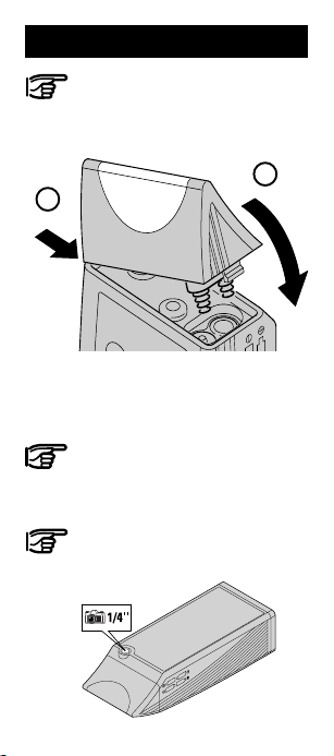
Insert Batteries
Fit batteries the right way round.
7. Insert end cover as shown below.
7.
8. Close end cover carefully.
Must click into place.
Never intentionally hit the end cover
against a hard object - the battery
compartment may be forced open!
To save power, the DISTO switches
off automatically after 90 seconds if
a key is not pressed.
8.
11
Page 12
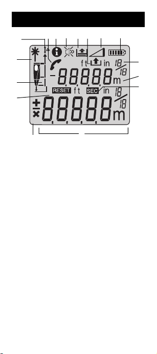
Display
16
14 13 12 11 10 9
15
1
2
3
4
Laser "on"
1
Measurement reference (rear, front,
2
stand)
Reset the instrument to factory
3
settings
Display of the mathematical
4
operators
Main display (e.g. measured
5
distance)
Time symbol for time delay release
6
Units (m / ft / ft in)
7
Auxiliary display, (e.g. area)
8
Battery display
9
Pythagoras function
10
Constant function
11
Recall last 20 values
12
Beep (on/off)
13
Information
14
Contact customer service
15
Offset adjustment (≠ 0)
16
12
8
7
6
5
Page 13
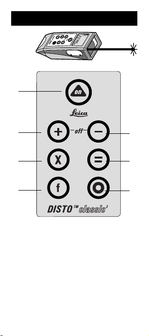
Keypad
1
2
3
4
On key and measurement key
1
Plus, forwards
2
Multiply
3
Functions
4
Menu, normal mode
5
Equals, enter
6
Minus, back
7
7
6
5
13
Page 14
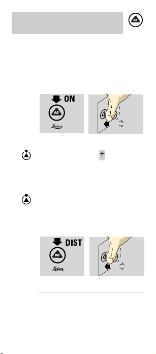
ON Key and Measurement Key
Measuring
Switch on DISTO.
In general for all keys:
Press and then release (basic function).
Switch on laser, the symbol
flashes on the display (automatic
switch off after 30 sec).
A second press starts the distance
measurement, "diSt" appears
briefly on the display.
14
Page 15
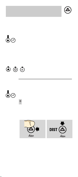
ON Key and Measurement
Key
Continuous measurement (Tracking)
A second, long press (approx.
1 sec) initiates continuous
measurement (tracking) mode.
"trc" appears on the display. The
measurements are repeated in a
fraction of a second.
; ; Stop.
Laser in continuous operation
In normal mode, press key until the
symbol is continuously
illuminated and a long "beep" is
heard.
A distance measurement is
triggered each time the key is
pressed.
15
Page 16
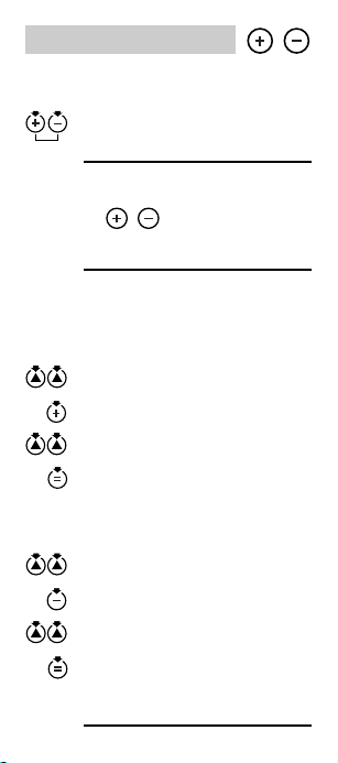
Plus/Minus Key
Quick switching off
Press simultaneously –
= Quick switch off of the DISTO.
In roll mode
In roll mode , have the function of a
cursor in the memory. (See page 19, 20)
Partial heights, chain values
Measurement + measurement =
sum / e.g. of partial heights
Measurement
Addition
Measurement
= Sum
Measurement – measurement =
difference
Measurement
Subtraction
Measurement
= Difference
In the same way chain values.
16
Page 17
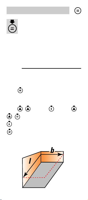
Multiplication Key
Area
Measurement x measurement = area
Measurement
Multiplication
Measurement
= Area
Volume
Measurement x measurement x
measurement
= Volume
Sum of areas
In the same way, areas/volumes can be
added together.
17
Page 18
Multiplication Key
Time delay release
Switch on
Keep pressed
On the screen it shows " " (delay) and
a number (delay in seconds) appear on
the display.
As long as the key is kept pressed, the delay
is increased.
Once the key is released, the seconds 59,
58, 57 ... remaining until the reading is made
are displayed. The last 5 secs. are counted
down with a "beep".
After the last "beep", the measurement is
made, the measured value can be read on
the display.
18
Page 19
Equal Key
Provides the results of
mathematical operations, such
as areas, volumes...
Settings are confirmed, in the same way as
"enter" is used on a PC.
Use selected setting or continue with
computing using called value.
Doubling a measured value
Using , a measured value can be very
easily doubled, e.g. for determining the
length of the walls in a room:
Using measure measure
half the length of the walls, then
and again
and the length of the walls is calculated.
19
Page 20
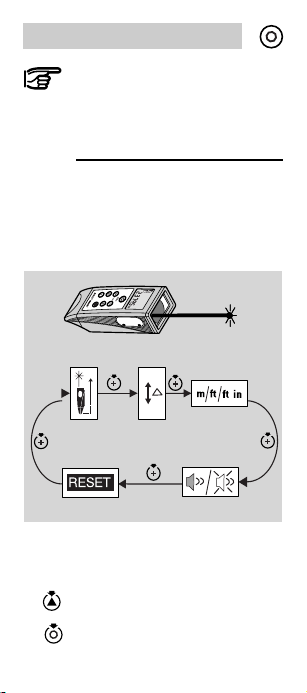
Setting Key
The Setting key places the DISTO
in the normal mode. This key has
the same function as "Clear" on a
PC.
Settings in roll mode
The instrument settings can be
changed in roll mode.
Reference Offset Units
Applies to all settings in roll
mode:
Switch on DISTO.
Press once briefly (normal mode).
BeepReset
20
Page 21

Setting key
Setting Key
Press a second time and keep
pressed until appears and the
settings are scrolled through in roll
mode. At the required setting,
release the key.
Are used to change between the
,
different displays.
Confirmation of a selection made.
Press briefly: the selection
made is undone and the instrument
returns to normal mode.
Setting reference only for one measurement
Switch on
flashes on the display.
front , stand (rear ).
start measurement.
21
Page 22

Setting Key
Set desired reference to "Permanent"
Switch on.
Press once, briefly.
Press a second time and keep pressed
until appears.
Press until appears flashing on the
display.
, set desired reference.
Confirm.
Possible settings:
rear front stand
After each setting of the
reference to "Permanent" we
recommend to reset again to
measurement from rear edge!
Please, make this a rule.
22
Page 23

Setting Key
Measure with additional tolerance
It is possible to determine dimensions with
additional tolerance e.g. by adding an offset
to the rear reference
Switch on.
Press once, briefly.
Press a second time and keep pressed
until and appear.
Press until appears flashing on the
display.
, Set required offset for the
reference.
The setting can be changed quickly by
holding down the , keys or the
key (fast setting).
Confirm setting.
To indicate that an offset has been set, the
symbol is displayed continuously.
23
Page 24

Setting Key
After making or changing settings, it is
imperative that a test measurement is
performed.
Please make this a rule:
After termination of the rough
size measurement always:
- set offset to 0.000 and
- set measurement from rear edge
Delete:
; ; ➜ ; ;
; ➜ ;
Unit - metre / feet / feet inch
Switch on.
Press once, briefly.
Press a second time and keep pressed
until and the current unit (e.g.: )
appears.
Press until the current unit appears
flashing on the display.
24
Page 25

Setting Key
, Select unit (m), (feet) or
(feet inch).
Confirm setting.
Beep during operation
Switch on.
Press once, briefly.
Press a second time and keep pressed
until and appear.
Press until appears flashing on the
display.
, Select on ( ) / off ( ).
Confirm setting.
25
Page 26

Setting Key
Resetting
Switch on.
Press once, briefly.
Press a second time and keep pressed
until and appear.
Press,
is displayed continuously and
flashes.
Stack is deleted or with:
Stack and constant displayed
deletes both or with:
Activate all settings and with
reset to:
- Reference rear edge
(normal setting),
- Offset,
- Beep (On),
- Stack and constant
(are deleted)
- Unit (metre)
26
Page 27

Function Key
Wait until display indicates 0!
Only then switch off.
Recall last measured value (stack)
Switch on DISTO.
Always place instrument in normal
mode.
Press twice, briefly.
The last value saved and the
symbol appear on the display.
The previous (older) values (max
19!) can be selected.
Page back.
Confirm selection for further use.
27
Page 28

Function Key
Saving a constant (Fnc 1)
Measure required value (e.g. room
height, area, volume).
Press until and appear
on the display.
Confirm, flashes.
( , ) Modify value.
Save constant.
Recalling the constant
Switch on DISTO.
Place instrument in normal mode.
Press briefly, and the constant
(e.g. ) appears on the
display.
Confirm, value is available for
further use (e.g. area calculation).
Any required function can be
selected using , after
"Fnc 1".
28
Page 29

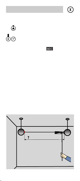
Function Key
Continuous measurement (Tracking) Maximum (Fnc 2)
Determine maximum
dimension, e.g. to
determine the (room)
diagonal.
Switch on DISTO.
Place instrument in normal mode.
Press until and
appear on the display.
Confirm function. Laser is on.
Aim with the DISTO at a point to
the left of the corner.
Activate continuous measurement.
Slowly rotate the DISTO to the right
past the corner.
Stop continuous measurement.
The room diagonal (e.g. )
is displayed.
29
Page 30

Function Key
Continuous measurement (Tracking) Minimum (Fnc 3)
Target point
Switch on DISTO.
Place instrument in normal mode.
Press until and appear
on the display.
Confirm function.
Aim DISTO approximately at the
target point.
Move the DISTO a large amount
around the target point. The
instrument calculates the variations
and determines the smallest value.
The two surfaces (e.g. floor /
ceiling) must be approximately
parallel.
Stop continuous measurement.
The smallest distance
(e.g. ) is displayed.
Determine the
minimum dimension,
e.g. ceiling height,
without having to
precisely align to the
normal (both axes).
30
Page 31

Function Key
Pythagoras, height measurement
(Fnc 4)
1
2
For estimating the height of buildings. Very
useful for making measurements from
standing position (no bending) if the height
is determined with three distances.
All three (two) points must lie on a vertical
plane on the wall.
Please follow the sequence given:
Switch on DISTO.
Press once (normal mode).
Press until and
appear on the display.
Confirm function.
Aim carefully at the upper point.
1
2
3
31
Page 32

Function Key
Trigger measurement; do not
move the instrument!
Accept value, "2 ---" appears on
the display. Point the DISTO
approximately horizontally.
Long press, a minimum
continuous measurement is
initiated.
Move the DISTO a large amount
around the ideal measurement
point.
Press briefly, continuous
measurement is stopped.
Accept value, "3 ---" appears on
the display.
End function, the height and
distance are displayed from two
measurements (Pythagoras).
32
Page 33

Function Key
Or:
Aim at third point.
Trigger measurement.
End function, the height and
distance are displayed from three
measurements (Pythagoras).
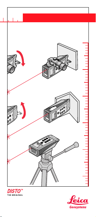
For short distances, a good base
behind the instrument is sufficient
for mechanical alignment.
After "2 ---", align the DISTO
approximately horizontally.
You will obtain the best results if
the DISTO is rotated around a
fixed point (rear edge, thread
position) and the axis of the laser
beam passes through this axis. So
do not simply place on a camera
tripod, in this case the axis of the
laser beam is approx. 70 to 100mm
above the centre of rotation, this
can lead to significant variations in
the height.
33
Page 34

User Information
Range
In daylight (outdoors) always work with laser
viewfinder. If necessary, shade the target.
Increased ranges:
At night, at dusk and when target area is in
the shade.
Reduced range:
The range of the DISTO can be reduced by
matt, green and blue surfaces (also by trees
or plants)
Rough Surfaces
On a rough surface (e.g. coarse plaster) a
mean value is indicated.
To avoid measuring to the bottom of plaster
joints:
Use target plate, 3M "Post-it" or board.
When aiming through panes of
glass, or if there are several
objects in the line of sight,
erroneous measurements can
occur.
34
Page 35

Transparent Surfaces
For reasons of safety and optics, never
measure against a clear liquid (e.g. water) or
clean glass (not dusty).
For materials and liquids unfamiliar to you
always take a trial measurement.
Wet, Smooth or High-Gloss Surfaces
1.If aiming at an angle, the laser beam is
reflected. The DISTO may receive a signal
that is too weak (error message E 255).
2.If aiming at a right angle, the DISTO may
receive a signal that is too strong (error
message E 256).
Illumination
Thanks to
fluorescence, you
can also see your
result in the dark. If
the display is placed
under a light source
(daylight, artificial
light), it will illuminate for more than 15
minutes! Without consuming any power!
35
Page 36

Environment
Suitable for use in an atmosphere
appropriate for permanent human
habitation. Cannot be used in an aggresive
or explosive environment.
Use in rain is permissible for limited periods.
Please pay attention to our Safety
Instruction.
Free-handed aiming
(approx. 20 - 40 m):
Produce target plate from cardboard etc.
and stick 4 target plates 563 875 to it; or:
Make your own target plates of any size:
Distance: Order:
to 30 m (white) Scotch Cal*
30 - 100 m (brown) Engineering-Grade 3279
* → Manufacturer 3MCompany
(7502 99 61 036)*
36
Page 37

Inclined, Round Surfaces
Can be measured with the laser:
Requirement: There is enough area on the
target surface for the laser spot.
In the field
Attach the viewfinder, and check it is
engaged by applying pressure from the side.
Setting the telescopic viewfinder
Keep pressed, laser on continously
( ).
Set up indoors, 5m, 10m or 30m from a wall.
Turn eyepiece slowly until crosshair and
laser spot are sharply focused.
37
Page 38

In the Field
Use the two screws (side, height) to adjust
the laser spot.
Example:
You are positioned exactly 5m in front of a
wall (approx. ± 0.5m). The laser spot must
be in the centre, exactly beside the 5m
distance mark.
In the field check adjustment from time to
time. (in the half-shade about 10-15m)
Aim with and without the red filter in position
(visibility is increased).
Accessories
Telescopic viewer (667478)
For easier aiming in the open.
For high precision aiming at larger
distances.
The laser spot on the object is particularly
easy to see in shaded areas if the red filter
is used.
38
Page 39

Accessories
Wrist strap (667491)
- safeguard against dropping,
- prevents injury.
Attach to fastening thread (1/4").
Adjust loop:
- So that DISTO does not slip from the
wrist,
- Loop does not need to be re-adjusted
every time
Shoulder strap (563 879)
Fasten to hand loop clip; adjustable over a
wide range.
Carrying pouch (667 169)
Black carrying pouch for protection against
knocks and dust.
Compartments for user manual, data cable,
telescopic viewfinder and palmtop computer.
Level (667 158)
For horizontal and vertical aiming, e.g. if
floor or wall is highly uneven.
Aiming accuracy about 1°, corresponding to
a measuring error of only about 5mm at
30m.
DISTO with this level is not a laser level.
39
Page 40

Accessories
Target plate (563875)
For poorly reflecting surfaces,
white side up to 40 - 50m,
over this distance the brown side with the
special reflection layer.
Up to over 100m
Combine several plates to one large target
area.
Holster (667489)
For max. protection. Fitted to belt.
(Can be reordered separately).
Software
Is continuously updated. Ask your Leica
Geosystems dealer or visit the DISTO web
site in the internet at
www.disto.com
40
Page 41

Safety Instructions
The following directions should enable the person
responsible for the DISTO, and the person who
actually uses the instrument, to anticipate and avoid
operational hazards.
The person responsible for the instrument must
ensure that all users understand these directions
and adhere to them.
Use of the Instrument
Permitted use
The permitted uses of the DISTO are the following:
- Measuring distances
- Computing areas and volumes
- Storing measurements
Prohibited uses
- Using the instrument without instruction
- Using outside the stated limits
- Deactivation of safety systems and removal of
explanatory and hazard labels
- Opening of the equipment by using tools
(screwdrivers etc.), as far as not specifically
permitted for certain cases.
- Carrying out modification or conversion of the
product
- Use after misappropriation
- Use of accessories from other manufacturers
without the express approval of Leica
Geosystems.
41
Page 42

Use of the Instrument
Prohibited uses (contd.)
- Deliberate or irresponsible behaviour on
scaffolding, when using ladders, when measuring
near machines which are running, or near parts of
machines or installations which are unprotected
- Aiming directly into the sun
- Deliberate dazzling of third parties; also in the
dark
WARNING:
Prohibited use can lead to injury,
malfunction, and material damage.
It is the task of the person responsible for the
instrument to inform the user about hazards and
how to counteract them. The DISTO is not to be
operated until the user has been instructed.
Limits to use
See section "Technical Data"
Environment:
Suitable for use in an atmosphere appropriate for
permanent human habitation. Cannot be used in an
aggresive or explosive environment.
Use in rain is permissible for limited periods.
42
Page 43

Areas of Responsibility
Responsibilities of the manufacturer of the
original equipment Leica Geosystems AG,
CH-9435 Heerbrugg (Leica Geosystems):
Leica Geosystems is responsible for supplying the
product, including the user manual and original
accessories, in a completely safe condition.
Responsibilities of the manufacturer of
non-Leica accessories:
The manufacturers of non-Leica
Geosystems accessories for the DISTO
are responsible for developing,
implementing and communicating safety concepts
for their products. They are also responsible for the
effectiveness of these safety concepts in
combination with the Leica Geosystems equipment.
Responsibilities of the person in charge
of the instrument:
WARNING:
The person responsible for the
instrument must ensure that the
equipment is used in accordance with the
instructions. This person is also
accountable for the deployment of
personnel and for their training and for
the safety of the equipment when in use.
The person in charge of the instrument has the
following duties:
- T o understand the safety instructions on the
product and the instructions in the User Manual.
- T o be familiar with local safety regulations relating
to accident prevention.
- T o inform Leica Geosystems immediately if the
equipment becomes unsafe.
43
Page 44

Hazards in Use
Important hazards in use
WARNING:
The absence of instruction, or the
inadequate imparting of instruction, can
lead to incorrect or prohibited use, and
can give rise to accidents with far-
reaching human, material, financial and
environmental consequences.
Precautions:
All users must follow the safety instructions given
by the manufacturer and the directions of the person
responsible for the instrument.
CAUTION:
Watch out for erroneous distance
measurements if the instrument is
defective or if it has been dropped or has
been misused or modified.
Precautions:
Carry out periodic test measurements. Particularly
after the instrument has been subject to abnormal
use, and before, during and after important
measurements.
CAUTION:
T ake care when aiming the DISTO
directly into the sun. The receiver lens
acts as a magnifying glass and can thus
cause damage to the instrument
internals.
Precautions:
Do not aim the DISTO directly at the sun.
44
Page 45

Hazards in Use
WARNING:
Insufficient securing or marking of your
measurement site could cause a
dangerous situation on the public
highway, building site, or in the factory
etc.
Precautions:
Always ensure your measurement site is
appropriately secured. Obey the local accident
prevention regulations, and road safety rules, at all
times.
CAUTION:
On sending the instrument, or on the
disposal of batteries that are not fully
discharged, a fire could be caused by
improper treatment.
Precautions:
Remove the batteries from their compartment
before sending the instrument. Dispose of batteries
only if they are completely discharged (operate the
instrument in tracking mode, until batteries are
completely discharged).
CAUTION:
If you do not intend using your instrument
for a long time, the batteries may leak
and damage your equipment!
Precautions:
Remove batteries if you are not going to use the
instrument for an extended period.
45
Page 46

Hazards in Use
WARNING:
If the equipment is improperly disposed
of, the following can happen:
- If plastic parts are burnt, poisonous
gases are produced which may impair
health.
- If batteries are damaged or
overheated, they can explode and
cause poisoning, burning, corrosion or
environmental contamination.
- By disposing of the equipment
irresponsibly you may enable
unauthorized persons to use it in
contravention of the regulations,
exposing themselves and third parties
to the risk of severe injury and
contaminating the environment.
Precautions:
Dispose of the equipment appropriately in
accordance with the regulations in force in your
country.
Always prevent access to the equipment by
unauthorized personnel.
46
Page 47

Laser Classification
The DISTO produces a visible laser beam which
emerges from the front of the instrument.
It is a Class 2 laser product in accordance with:
- IEC825-1: 1993 "Radiation safety of laser
products"
- EN60825-1: 1994 "Radiation safety of laser
products"
It is a Class II laser product in accordance with:
- FDA 21CFR Ch.I §1040: 1988 (US Department of
Health and Human Service, Code of Federal
Regulations)
Laser Class 2/II products:
Do not stare into the laser beam or direct it towards
other people unnecessarily. Eye protection is
normally afforded by aversion responses including
the blink reflex.
WARNING:
Looking directly into the beam with
optical aids (e.g. binoculars, telescopes)
can be hazardous.
Precautions:
Do not look directly into the beam with optical aids.
47
Page 48

Labelling
Max. em itted Pow er :
Maximum radiant power : 0.95mW
Em itted Wavelenght :
Emitted wavelength : 620-690nm
Standard applied : EN60825-1:1994-07
Standard ap plied :
0.95mW c.w.
620-690nm
EN 60825-1 : 1994-07
IEC825-1 : 1993-11
IEC825-1 : 1993-11
Laser beam
outlet
48
Page 49

Labelling
49
Page 50

Labelling
Beam divergence: 0.16 x 0.6 mrad
Pulse duration: 15×10-9 s
Maximum radiant power: 0.95 mW*
* Measurement uncertainty: ±5%
Maximum radiant power per pulse: 8 mW
CAUTION:
Allow only authorized Leica Geosystems
service workshops to service the
instruments.
DISTO with Telescopic Viewfinder
WARNING:
Looking right at the reflected laser beam
in a DISTO operated with telescopic
viewfinder could be dangerous when you
aim at areas that reflect like a mirror, or
emit reflections unexpectedly (e.g. a
mirror, metallic surfaces, windows,
prisms, liquids).
Precautions:
If you using a telescopic viewfinder, do not aim at
areas that are reflective like a mirror, or which could
produce unintended reflections (e.g. mirrors,
metallic surfaces, windows, prisms).
50
Page 51

Electromagnetic Compatibility
(EMC)
The term "electromagnetic compatibility" is taken to
mean the capability of the DISTO to function
smoothly in an environment where electromagnetic
radiation and electrostatic discharges are present,
and without causing electromagnetic interference to
other equipment.
WARNING:
Electromagnetic radiation can cause
interference in other equipment.
Although the DISTO meets the strict regulations and
standards which are in force in this respect, Leica
Geosystems cannot completely exclude the
possibility that interference may be caused to other
equipment.
CAUTION:
Interference caused by electromagnetic
radiation can result in the tolerance limits
for measurements being exceeded.
Although the DISTO meets the strict regulations and
standards which are in force in this respect, Leica
Geosystems cannot completely exclude the
possibility that interference may be caused to the
DISTO by very intensive electromagnetic radiation,
for instance near radio transmitters, walkie-talkies,
diesel generators etc.
Under such conditions, check measurement results
for their plausibility.
51
Page 52

FCC Statement (applic. in U.S.)
WARNING:
This equipment has been tested and
found to comply with the limits for a
Class B digital device, pursuant to part 15 of the
FCC Rules.
These limits are designed to provide reasonable
protection against harmful interference in a
residential installation.
This equipment generates, uses and can radiate
radio frequency energy and, if not installed and
used in accordance with the instructions, may
cause harmful interference to radio
communications.
However, there is no guarantee that interference will
not occur in a particular installation.
If this equipment does cause harmful interference to
radio or television reception, which can be
determined by turning the equipment off and on, the
user is encouraged to try to correct the interference
by one or more of the following measures:
- Reorient or relocate the receiving antenna.
- Increase the separation between the equipment
and receiver.
- Connect the equipment into an outlet on a circuit
different from that to which the receiver is
connected.
- Consult the dealer or an experienced radio/TV
technician for help.
52
Page 53

FCC Statement (applic. in U.S.)
WARNING:
Changes or modifications not expressly
approved by Leica Geosystems for
compliance could void the user’s authority to
operate the equipment.
Product labelling:
This device complies with part 15 of the FCC
Rules. Operation is subject to the following two
conditions: (1) This device may not cause harmful
interference, and (2) this device must accept any
interference received, including interference that
may cause undesired operation.
53
Page 54

Care and Storage
Care
Clean and dry
- Blow away dust from lenses.
- Do not touch glass with fingers.
- Only clean with a soft cloth; if
necessary, damp with pure alcohol.
Do not use other cleaning agents.
Plastic parts could be affected.
Wipe off splashes of cement, plaster etc. as quickly
as possible, using water and a damp cloth or
sponge. Look after the optical surfaces with the
same care that you would apply to spectacles,
cameras and field glasses.
Storage
Please respect the temperature limits,
specially during summer when storing
the equipment inside a vehicle
(-40°C to +70°C / -40°F to +158°F).
Unpack instruments and accessories that
have become wet. Dry off the instrument,
container and accessories (at maximum
40 ºC / 108 ºF) and clean. Only repack
the equipment when it is completely dry.
After longer periods of storage or
transport carry out a check measurement
before using the equipment.
54
Page 55

Storage
If the indoor and outdoor temperatures are very
different, allow time for the instrument to adapt.
If the DISTO is removed from an air-conditioned
room and exposed to warm damp air, the instrument
and the optics will fog over. To reduce this effect,
cover the instrument with a cloth and allow it to
adapt slowly to the new conditions as you would for
a camera or a video.
Transport
The Leica Geosystems holster protects the DISTO
well against mechanical shock, but not against
water or dust.
It is recommended that you always transport the
DISTO in the Leica Geosystems holster or an
equivalent protective container or packaging.
Do not exceed the temperature limits.
Before embarking on a flight, enquire whether you
are permitted the DISTO as hand luggage.
Despatch
Always use the original Leica
Geosystems packaging (holster and
shipment box) for sending the instrument.
You must remove the batteries (send the instrument
without batteries).
55
Page 56

Message Codes
Message Cause Remedy
code
203 Wrong entry Repeat entry
204 Calculation Repeat
error procedure
252 Temperature above Cool down
50°C (measuring) instrument
253 Temperature below Warm up
-10°C (measuring) instrument
255 Receiver signal Use target plate
too weak, Measurement
Measurement time > 10 sec.
time too long
Distance < 250 mm
256 Receiver signal Use target plate
too powerful (correct side)
257 Wrong Use target plate
measurement;
ambient brightness
too high
All other messages Call service
General rule:
In case of messages switch on/off instrument
several times and check if message is still
displayed. Then call service and specify the
message displayed.
Reset message with or quick-switch off
„System“
56
Page 57

Technical Data
Measuring accuracy
Smallest unit
displayed
Time for a
measurement
visible
∅ Laser-spot
at Distance
Outdoor measurements
(adaption for viewfinder)
Two line display
Illumination
(fluorescent display)
Measure from corners
Constant (height)
Continuous measurement max.
(room diagonals)
Continuous measurement min.
(room diagonals)
Height (width) from two
measurements (Pythagoras)
Time delay release
20 last values
Over 3000 measurements
Splash proof
Dust proof
Range
typ.
max.
0.3m to
over 100m**
0.5...~ 4s
0.16...~1s
635nm
Type AAA,
4x1,5V
57
Page 58

Remarks on Measuring Accuracy
*The measuring accuracy corresponds to the ISOrecommendation ISO/R 1938-1971 with a statistical
confidence level of 95% (i.e. ± twice the standard
deviation, refer to diagram below).
The typical measuring accuracy relates to average
conditions for measuring within the specified range.
It is not valid for the user functions Fnc 2, 3, 4, and
is not valid in the tracking mode.
The maximum measuring error relates to
unfavourable conditions such as:
- highly-reflecting surfaces (e.g. reflector tapes),
- operating at the limits of the permitted
temperature range, adaption to ambient
temperature interrupted (page 54)
- very bright ambient conditions, strong heat
shimmer and can be up to ± 5 mm (twice the
standard deviation).
**At long range ± 30 ppm (± 3 mm/100 m) plus
short range error. Range increases, the better the
laserlight is reflected from the target area (diffuse,
not reflective), and the brighter the laserpoint is
compared to the surrounding luminosity (indoors,
dawn).
From appr. 40 - 50 m use target plate, brown side
(page 40)
58
Page 59

Remarks on Measuring
Accuracy
Possible method of calculating the standard
deviation s:
When using a computer with a statistical function or
if you use the program Excel, you can calculate the
mean value and the standard deviation s
directly from the 10 measured values.
Formula for the standard deviation s:
n ... number of measurements
... individual value of a series of
x
i
measurements
... mean value of a series of measurements
Calculation using the program Excel:
On the Insert menu, choose Functions.
Select category: Statistics and Function:STABW
within the Function Assistant.
Depending on the version of Excel and the
language used, the names of the menu may vary.
59
Page 60

Set Mark for Viewfinder
Centre of
viewfinder
Laser point
Setting mark for adjusting the telescopic
viewfinder
see page 36, 37
34 mm
Please copy the above diagram 1:1.
60
Page 61

Accuracy Tests
Accuracy tests on the DISTO for users certified to
ISO 900...:
You can perform your own accuracy tests on the
DISTO to meet the requirements of ISO 900... for
measuring equipment.
T ake a fixed, invariable, and conveniently
accessible distance of about 1m to 10m, such as
the width of a window opening or of a room.
Measure it ten times.
Determine the magnitude of this distance with a
means of measurement that is monitored by a
national, accredited calibration institute (traceability
back to national standards).
Determine the amount that the measurements vary
from the nominal distance, and compute the
standard deviation (page 59).
Record the standard deviation and set a date for the
next test. Repeat these tests at frequent and regular
intervals, also before and after important measuring
jobs.
Affix an adhesive label on the DISTO for accuracy
tests of measuring equipment and keep a detailed
record of the test procedure.
Your DIST O meets the specified accuracy if
standard deviation remains smaller or equal to the
typical specified value.
61
Page 62

Accuracy Tests
A DISTO whose measuring accuracy has been
tested over a test distance works within the
specified tolerance over the entire distance and
temperature range specified in the manual.
Please note the technical data and the description
of measuring accuracy in the manual (page 59).
62
Page 63

Leica Geosystems AG, Heerbrugg,
Switzerland, has been certified by SQS
as being equipped with a quality system
which meets the International Standard
of Quality Management and Quality
Systems (ISO standard 9001) and
Environmental Management Systems
(ISO standard 14001).
6otal Quality Management -
Our commitment to total
customer satisfaction
Ask your local Leica Geosystems
agent for more information
about our TQM program
Your dealer:
63
Page 64

Leica Geosystems AG
CH-9435 Heerbrugg
(Switzerland)
www.leica-geosystems.com
712791-0.0.1en
Printed in Switzerland Copyright by Leica Geosystems AG, Heerbrugg,
Switzerland 2000
 Loading...