

Page 1
Instruction manual
Leica CM3600
English V6.0 08/2006
Always keep this manual near the instrument.
Read carefully prior to operating the instrument
Order No.: 0708 35101
Leica CM3600
Cryomacrotome
Page 2

NOTE
The information, numerical data, notes and value
judgments contained in this manual represent the
current state of scientific knowledge and stateof-the-art technology as we understand it following thorough investigation in this field. We are
under no obligation to update the present manual
periodically and on an ongoing basis according
to the latest technical developments, nor to provide our customers with additional copies, updates etc. of this manual.
For erroneous statements, drawings, technical
illustrations etc. contained in this manual we exclude liability as far as permissible according to
the national legal system applicable in each individual case. In particular, no liability whatsoever
is accepted for any financial loss or consequential damage caused by or related to compliance
with statements or other information in this
manual..
Statements, drawings, illustrations and other information as regards contents or technical details of the present manual are not to be considered as warranted characteristics of our
products.
. These are determined only by the contract provisions agreed between ourselves and our customers.
Leica reserves the right to change technical
specifications as well as manufacturing processes without prior notice. Only in this way is it
possible to continuously improve the technology
and manufacturing techniques used in our products.
This document is protected under copyright laws.
Any copyrights of this document are retained by
Leica Microsystems Nussloch GmbH.
ny reproduction of text and illustrations (or of any
parts thereof) by means of print, photocopy, microfiche, web cam or other methods – including
any electronic systems and media – requires express prior permission in writing by Leica
Microsystems Nussloch GmbH.
For the instrument serial number and year of
manufacture, please refer to the name plate at
the back of the instrument.
© Leica Microsystems Nussloch GmbH
Published by:
Leica Microsystems Nussloch GmbH
Heidelberger Str. 17 - 19
D-69226 Nussloch
Germany
Telephone: +49 62 24 143-0
Facsimile: +49 62 24 143-200
E-mail: histo_info@leica-microsystems.com
Internet : http://www.histo-solutions.com
2
Instruction manual V 6.0 - 08/2006
Page 3

EC Declaration of conformity
We herewith declare in exclusive responsibility that the
Leica CM 3600 – Cryomacrotome
was developed, designed and manufactured to conform with:
Council Directive 89/392/EEC, Appendix II A (Machines),
Council Directive 73/23/EEC (low voltage) and
Council Directive 89/336/EEC, Appendix I (Electromagnetic compatibility),
including their amendments.
The following harmonized standards were applied:
DIN EN 292,
DIN EN 378 Part 1, DIN EN 61010-1.
The following national standards, guidelines and specifications were applied: MedGV.
In addition, the following in-house standards were applied:
DIN EN 9001.
A complete set of technical documentation is available.
An instruction manual for subject product is available.
Leica Microsystems Nussloch GmbH
Postfach 1120
D-69222 Nussloch
Germany
December 13, 1995
Leica CM3600 – Cryomacrotome
. . . . . . . . . . . . . . . . . . . . . . . . . . . .
Dag Graupner
Managing Director
3
Page 4

Index
1. Important notes ................................................................................................................... 8
1.1 Symbols in the text and their meaning ............................................................................................................................ 8
1.2 Qualification of personnel .................................................................................................................................................. 8
1.3 Instrument type .................................................................................................................................................................... 8
1.4 Designated use ..................................................................................................................................................................... 9
1.5 Warranty .............................................................................................................................................................................. 10
1.6 Service information ........................................................................................................................................................... 10
1.7 Decommissioning and disposal ...................................................................................................................................... 10
2. Characteristics of the Leica CM3600 ............................................................................ 12
2.1 Layout of the CM3600 ........................................................................................................................................................ 12
2.2 Technical Data ................................................................................................................................................................... 14
2.2.1 Microtome type...................................................................................................................................................... 14
2.2.2 Control unit ......................................................................................................................................................... 14
2.2.3 Dimensions and weight ........................................................................................................................................ 15
2.2.4 Electrical connections ......................................................................................................................................... 15
2.2.5 Refrigeration system - cooling chamber .......................................................................................................... 16
2.2.6 General parameters .............................................................................................................................................. 17
2.3 Instrument parts................................................................................................................................................................. 17
2.4 Function ............................................................................................................................................................................... 17
3. Safety................................................................................................................................... 20
3.1 Safety instructions............................................................................................................................................................. 20
3.2 Warnings ............................................................................................................................................................................. 20
3.3 Safety standards ................................................................................................................................................................ 21
3.4 Safety devices .................................................................................................................................................................... 21
3.4.1 Emergency stop switch ........................................................................................................................................ 21
3.4.2 Knee lever ......................................................................................................................................................... 22
3.4.3 Window ......................................................................................................................................................... 22
3.4.4 Cryochamber ......................................................................................................................................................... 22
3.5 Special safety instructions .............................................................................................................................................. 23
4. Site requirements .............................................................................................................26
4.1 Site requirements at place of installation .................................................................................................................... 26
4.2 Electrical connections ...................................................................................................................................................... 27
4.3 Other connections ............................................................................................................................................................. 27
5 Installation ......................................................................................................................... 28
5.1 Unpacking and installation .............................................................................................................................................. 28
5.2 Standard delivery ............................................................................................................................................................... 28
5.3 Port and switch panel ....................................................................................................................................................... 29
5.3.1 Port and switch functions .................................................................................................................................... 30
4
Instruction manual V 6.0 - 08/2006
Page 5

Index
5.3.2 Fuses ......................................................................................................................................................... 31
5.4 PC .......................................................................................................................................................................................... 33
6. Software ............................................................................................................................. 34
6.1 Start and log-in procedure .............................................................................................................................................. 34
6.2 Description of the window elements ............................................................................................................................. 35
6.2.1 Title bar ......................................................................................................................................................... 35
6.2.2 Tool bar ......................................................................................................................................................... 35
6.2.3 Work space ......................................................................................................................................................... 37
6.2.4 Information bar ...................................................................................................................................................... 37
6.3 Initialization ......................................................................................................................................................................... 38
6.4 Main window ...................................................................................................................................................................... 40
6.4.1 Chamber temperature .......................................................................................................................................... 41
6.4.2 Time 41
6.4.3 Automatic defrost cycle ....................................................................................................................................... 41
6.4.4 Automatic dehydration ......................................................................................................................................... 42
6.4.5 Knife movement ..................................................................................................................................................... 42
6.4.6 Extraction system .................................................................................................................................................. 45
6.4.7 Sectioning program .............................................................................................................................................. 45
6.4.8 Sledge speed 46
6.4.9 Mode of operation ................................................................................................................................................. 47
6.4.10 Cutting window ....................................................................................................................................................... 48
6.5 Parameter settings ............................................................................................................................................................ 49
6.5.1 Parameter setting.................................................................................................................................................. 50
6.5.2 Password list ......................................................................................................................................................... 54
6.5.3 Configuration ......................................................................................................................................................... 57
6.5.4 Reference voltages ............................................................................................................................................... 64
6.5.5 Language selection............................................................................................................................................... 64
6.5.6 Initialization ......................................................................................................................................................... 64
6.6 Temperature curves .......................................................................................................................................................... 65
6.6.1 Work space ......................................................................................................................................................... 66
6.6.2 Diagram ......................................................................................................................................................... 68
6.7 Chronological event list .................................................................................................................................................... 69
6.7.1 Work space ......................................................................................................................................................... 70
6.7.2 Event table ...............................................................................................................
6.8 Alarm list .............................................................................................................................................................................. 73
6.8.1 Work space ......................................................................................................................................................... 74
6.8.2 Event table ......................................................................................................................................................... 75
6.8.3 Error codes: meaning and troubleshooting ..................................................................................................... 76
6.9 Chamber illumination ........................................................................................................................................................ 77
6.10 Section documentation .................................................................................................................................................... 77
6.10.1 Tree diagram ......................................................................................................................................................... 78
6.10.2 Studies protocol ..................................................................................................................................................... 79
6.10.3 Event table ......................................................................................................................................................... 82
6.11 Photo mode ......................................................................................................................................................................... 83
.......................................... 72
Leica CM3600 – Cryomacrotome
5
Page 6

Index
6.12 Screen printout................................................................................................................................................................... 83
6.13 Remote inquiry .................................................................................................................................................................... 84
6.14 Help ....................................................................................................................................................................................... 86
6.15 Saving ................................................................................................................................................................................... 86
6.16 Printing labels ..................................................................................................................................................................... 86
6.17 Foot switch .......................................................................................................................................................................... 86
6.18 User log-in / log-out ........................................................................................................................................................... 87
6.19 Quitting the application .................................................................................................................................................... 87
7. Operating the Leica CM3600 ........................................................................................... 88
7.1 Check list ............................................................................................................................................................................. 88
7.2 Switching the instrument on ........................................................................................................................................... 89
7.3 Starting the software ........................................................................................................................................................ 89
7.4 Setting the chamber temperature .................................................................................................................................. 89
7.5 Specimen stages ................................................................................................................................................................ 90
7.5.1 Inserting the specimen stage, orientable, with ball-joint ............................................................................. 92
7.5.2 Inserting the specimen stage, non-orientable ............................................................................................... 94
7.6 Knife ...................................................................................................................................................................................... 96
7.6.1 Inserting standard knives .................................................................................................................................... 98
7.6.2 Inserting the disposable blade holder with disposable blade ................................................................... 100
7.6.3 Adjusting the knife angle ................................................................................................................................... 102
7.7 Setting the trimming parameters .................................................................................................................................. 103
7.8 Setting the sectioning parameters .............................................................................................................................. 104
7.8.1 Sectioning the specimen ................................................................................................................................... 104
7.8.2 Collecting the sections ....................................................................................................................................... 104
7.9 Dehydrating the sections ............................................................................................................................................... 106
8. Cleaning and maintenance ........................................................................................... 108
8.1 Cleaning ............................................................................................................................................................................. 108
8.1.2 Removing the microtome from the cryochamber ......................................................................................... 108
8.2 Maintenance ..................................................................................................................................................................... 110
8.2.1 Oiling ....................................................................................................................................................... 110
8.2.2 Defrosting ....................................................................................................................................................... 111
9. Optional accessories ..................................................................................................... 112
9.1 Extraction system ............................................................................................................................................................ 112
9.1.1 Design and function of the extraction system .............................................................................................. 112
9.1.2 Exchanging the disposable bag ....................................................................................................................... 114
9.2 Ordering information ....................................................................................................................................................... 115
6
Instruction manual V 6.0 - 08/2006
Page 7

Index
Leica CM3600 – Cryomacrotome
7
Page 8
1. Important notes
1.1 Symbols in the text and their meaning
Warnings appear in a grey box and
are marked with a warning triangle
.
Notes, i.e. important user information
appear in a grey box and are marked
with an information symbol .
Buttons and function keys which need
ENTER
(5)
to be pushed on the data entry screen,
are printed in bold capitals.
Figures in brackets refer to item numbers in drawings.
1.2 Qualification of personnel
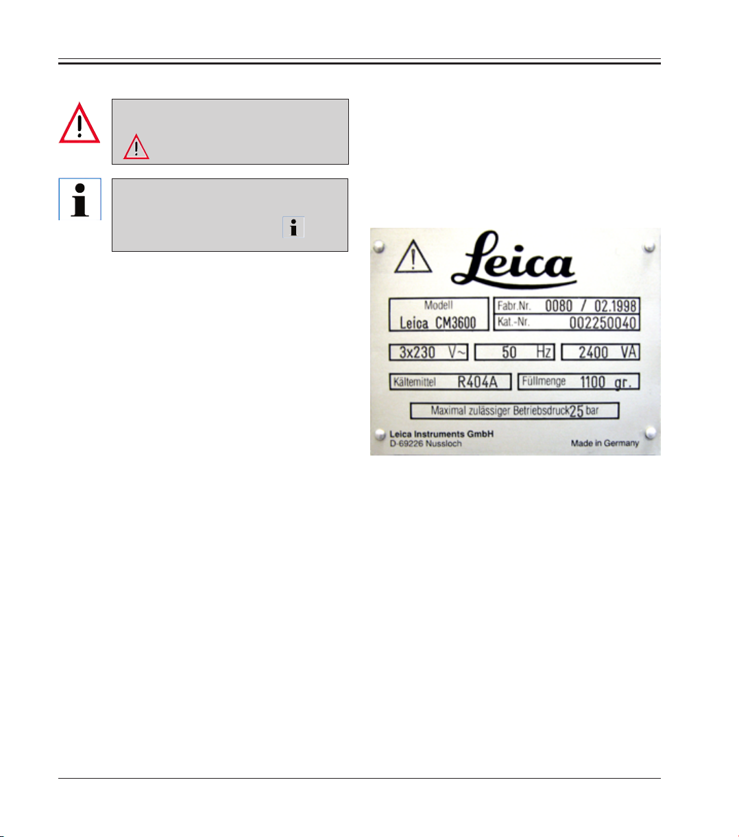
1.3 Instrument type
All information contained in this instruction
manual applies exclusively to the instrument type
indicated on the title page.
A name plate bearing the instrument serial number is attached to the back of the instrument.
Only trained laboratory personnel may operate the
Leica CM3600.
Prior to operating the instrument, the operator
must thoroughly read and understand this instruction manual and must familiarize him/herself with
all technical details of the instrument.
8
Instruction manual V 6.0 - 08/2006
Page 9
1.4 Designated use
1. Important notes
The Leica CM3600 is an SPS-controlled and motorized precision
cryomacrotome for large-surface sections, equipped with a convectioncooled cryochamber for deep-freezing, sectioning, storing and freezedrying large biological and industrial specimens.
The instrument is designed for the above described applications only and
must be operated according to the instructions in the present instruction
manual.
Any other use of the instrument is considered improper.
If you wish to use the instrument for special applications or modes of
operation not listed in this manual, it is absolutely necessary that you
contact your local Leica representation prior to doing so.
Otherwise, you will loose the Leica warranty on your instrument.
Only trained personnel, skilled in the use of the above-mentioned applications, may operate the Leica CM3600.
Prior to operating the instrument, the operator must thoroughly read and
understand this instruction manual.
Leica CM3600 – Cryomacrotome
9
Page 10

1. Important notes
1.5 Warranty
Leica Microsystems Nussloch GmbH guarantees that the contractual product delivered has been subjected to a comprehensive quality control procedure based on the Leica in-house testing standards, and that the product is
faultless and complies with all technical specifications and/or agreed characteristics warranted.
The scope of the warranty is based on the content of the concluded agreement. The warranty terms of your Leica sales organization or the organization from which you have purchased the contractual product shall apply
exclusively.
1.6 Service information
If you require technical service or replacement parts, please contact your
Leica sales representative or Leica dealer who sold the product..
Please provide the following information:
• Model name and serial number of the instrument
• Location of the instrument and name of the person to contact
• Reason for the service call
• Date of delivery
1.7 Decommissioning and disposal
The instrument or parts of the instrument must be disposed of in compliance
with the local laws.
10
Instruction manual V 6.0 - 08/2006
Page 11

1. Important notes
Leica CM3600 – Cryomacrotome
11
Page 12
2. Characteristics of the Leica CM3600
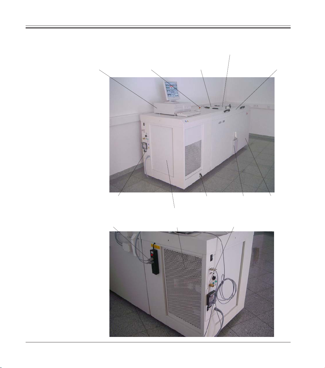
2.1 Layout of the CM3600
PC
Port and switch panel
switch
Window Chamber lidEmergency stop
Drain tap
Microtome
(in chamber)
Knee lever
Chamber
12
Socket panel
Refrigeration
and control unit
Port and switch panel
Instruction manual V 6.0 - 08/2006
Page 13

2. Characteristics of the Leica CM3600
Drain tap
Condensation water is drained through the drain tap.
Refrigeration and control unit
The refrigeration and control unit cools the cryochamber and controls the
microtome and the entire electronics.
Knee lever
The knee lever is used for manual operation of the specimen sledge.
Socket panel
The PC and peripherals are connected via the socket panel.
PC
Commercial PC, monitor, keyboard, mouse and internal modem.
Emergency stop switch
Press the emergency stop switch to stop the microtome immediately.
Cabinet
The cabinet contains the cryochamber which houses the microtome.
Chamber lid
The chamber lid can be opened completely for maintenance and cleaning
work on microtome and/or cryochamber.
Window
The window is heated and can be opened completely.
Microtome
The microtome is used to section the specimens.
Port and switch panel
The port and switch panel contains the mains switch and several sockets
and ports.
Leica CM3600 – Cryomacrotome
13
Page 14

2. Characteristics of the Leica CM3600
2.2 Technical Data
2.2.1 Microtome type
450 C Sliding microtome
Section thickness selection: 1 - 200 μm
Sectioning range: 0 - 450 mm
Max. sectioning speed: 80 mm/s
Knife retraction after sectioning stroke: 50 - 250 μm
Total vertical stroke of knife: 70 mm (standard)
Total vertical stroke of knife: 100 mm (model with
Total horizontal stroke: 450 mm
Specimen orientation via ball-joint: ca. 5° (x/y/z axis)
Specimen orientation w/large spec. stage
(450 x 150 mm): Rotation around
Maximum specimen size (L x W x H): 450 x 150 x 70 mm
Maximum specimen size (L x W x H): 450 x 150 x 200 mm
Knife holder for steel and
Tungsten Carbide knives: 160 mm
Knife holder for disposable blade holder: 160 mm
Knife (160 mm) with facet angle of: 20°, 35°
extended vertical
stroke)
longitudinal axis (x axis)
(standard)
(model with extended
stroke length)
2.2.2 Control unit
14
The Leica CM3600 is equipped with a commercial PC, monitor, keyboard,
mouse and an internal modem. For further information, please refer to the
manual of the PC.
Operating system: XP.
Software: CM3600 Version 3.0.0.
Instruction manual V 6.0 - 08/2006
Page 15

2.2.3 Dimensions and weight
Inner (cryochamber L x H x W): 1650 x 720 x 600 mm
Outer (L x H x W): 2800 x 1090 x 920 mm
(Overall dimensions with
connecting cables)
Outer length (total): 2800 mm
Outer length (chamber only): 1940 mm
Outer length (control unit
with connections only): 860 mm
Outer height (total): 1090 mm
Outer height (work surface height): 1050 mm
Outer width: 920 mm
Weight (total, incl. microtome): 660 kgs
Weight (microtome only): 190 kgs
2.2.4 Electrical connections
380 V / 50 Hz, three-phase
Nominal voltage: 380 V AC ± 10 %
Nominal frequency: 50 Hz
Power draw: 2300 VA
Automatic cutout/ 3 x 8A / 1 x 16A,
mains safety switch according to DIN IEC 127-2
2. Characteristics of the Leica CM3600
208 V / 60 Hz, two-phase
Nominal voltage: 208 V AC ± 10 %
Nominal frequency: 60 Hz
Power draw: 2300 VA
Automatic cutout/ 2 x 8A / 1 x 10A
Mains safety switch UL-listed
Leica CM3600 – Cryomacrotome
15
Page 16

2. Characteristics of the Leica CM3600
200 V / 50 Hz, two-phase
Nominal voltage: 200 V AC ± 10 %
Nominal frequency: 50 Hz
Power draw: 2300 VA
Automatic cutout/ 2 x 8A / 1 x 10A
Mains safety switch UL-listed
200 V / 60 Hz, two-phase
Nominal voltage: 200 V AC ± 10 %
Nominal frequency: 60 Hz
Power draw: 2300 VA
Automatic cutout/ 2 x 8A / 1 x 10A
Mains safety switch UL-listed
2.2.5 Refrigeration system - cooling chamber
Selectable temperature range: 0° C to -30° C
at ambient temperature of
22° C, with window closed
and relative humidity ≤ 60 %: -30° C ±10 % (selectable
Control accuracy: +1 to -3 K
Electrical power draw: 1160 W
Refrigerating output at -25°C: 1370 W
Nominal pressure: 20 bar (maximum value)
Cutoff pressure: 25 bar (via Pressostat)
Safety factor: 2, as per UL 1262
Refrigerant: 1100 g, refrigerant R404A
Compressor oil: 1220 ccm alpha 22, Kyodo
in 1 K steps)
16
Defrosting: automatic hot-gas defrosting, programmable,
2 x automatic hot-gas defrosting cycles / 24 hours.
Duration: 1 - 15 minutes, manual defrosting as
needed.
Instruction manual V 6.0 - 08/2006
Page 17

2.2.6 General parameters
2.3 Instrument parts
2. Characteristics of the Leica CM3600
Protective class: I
Pollution degree: 2
Overvoltage installation category: II
The Leica CM3600 consists of a sliding microtome in a large-volume
cryochamber. The instrument is designed for cryosectioning large specimens or for processing specimens with the so-called cryo-planing
technique.
The large-scale heavy-duty microtome is made for sectioning large
biomedical and industrial specimens such as whole animals or large
tissue specimens by applying the sectioning techniques for large-surface
sections. The sturdy construction of the instrument also permits sectioning very hard specimens such as undecalcified bones.
The microtome is housed in a convection-cooled large-volume
cryochamber.
The large chamber in connection with the special cooling system enables
dehydration of sections within a very short time.
The low temperatures are achieved and maintained by cold air circulating
inside the cryochamber. A fan controls the air circulation speed.
The large specimens are frozen onto metal specimen stages which are
subsequently clamped in the specimen sledge.
Optionally the instrument can be operated with an extraction system
which largely prevents the cryochamber being soiled with section waste.
2.4 Function
The motor-driven specimen sledge moves horizontally underneath the
knife, either producing a section (cryosectioning) with each stroke or a
high-quality specimen surface (cryo-planing technique).
Leica CM3600 – Cryomacrotome
17
Page 18

2. Characteristics of the Leica CM3600
Prior to each sectioning stroke, a stepper motor feeds the microtome
knife downwards towards the specimen by a selected amount of microns
(section thickness).
During each return stroke of the specimen sledge, the stepper motor
automatically carries out a knife retraction movement, programmable
between 50 and 250 μm. This protects both the knife edge and the specimen surface from being damaged.
Before starting the next sectioning stroke, the motor lowers the knife
towards the specimen surface by the selected sectioning feed plus the
set value for knife retraction.
Trimming is programmable; the desired section thickness can be
preselected.
The number of sections to be preformed during trimming can be programmed via the section counter. When the programmed number of
sections has been carried out, the microtome will stop automatically.
Once the desired specimen block height has been reached, those sections that will actually be used for further examination are collected
manually via the knee lever.
The Leica CM3600 is operated via PC and/or manually via the knee lever.
All data entries are made via the PC.
The Leica CM3600 features two automatic defrost cycles.
Defrost cycle duration is software-controlled. If the evaporator surface is
already completely deiced before the programmed defrost time is up, the
defrost cycle will be aborted. In addition, manual defrost cycles can be
set as needed.
18
Instruction manual V 6.0 - 08/2006
Page 19

2. Characteristics of the Leica CM3600
Leica CM3600 – Cryomacrotome
19
Page 20
3. Safety
Be sure to comply with the safety instructions and warnings in this chapter.
Read these instructions, even if you are already familiar with the operation and use of
other Leica products.
3.1 Safety instructions
This instruction manual contains important instructions and information regarding the operational safety and maintenance of the instrument.
The instruction manual is an important part of the
product, which must be read carefully prior to
setup and use and must always be kept near the
instrument.
This Instruction manual must be appropriately supplemented as required by the existing regulations
on accident prevention and environmental safety in the operator‘s
country.
The protective devices on both instrument and accessories must neither be removed nor
modified. Only qualified service personnel authorized by Leica may repair the instrument
and access its internal components.
The Leica CM3600 was built and tested in accordance with the safety regulations for electrical
measuring, control, regulating and laboratory
devices listed below:
• DIN EN ISO 9001,
• EN 61010-1, EN 61010-2-010,
• EN 292-1, EN 292-2,
• EN 614-1,
• EN 954-1,
• EN 1050,
• EN 61326-1,
• EN 61000-3-3
In order to maintain this condition and ensure safe
operation, the operator must observe all the instructions and warnings contained in this instruction manual.
3.2 Warnings
The safety devices installed in this instrument by the manufacturer only constitute the basis for
accident prevention. Primarily responsible for accident-free operation is above all the institution
which owns the instrument and, in addition, the designated personnel who operates, services or
repairs the instrument.
To ensure trouble-free operation of the instrument, be sure to comply with the following instructions and warnings.
20
Instruction manual V 6.0 - 08/2006
Page 21
3.3 Safety standards
The Leica CM3600 was built and tested in accordance with the safety
regulations for electrical measuring, control, regulating and laboratory
devices listed below:
• DIN EN 292,
• DIN EN 55011,
• DIN EN 61010-1,
• IEC 1000-4,
• IEC 50082-1,
• MedGV.
In order to maintain this condition and ensure safe operation, the operator must observe all the instructions and warnings contained in this
instruction manual.
3.4 Safety devices
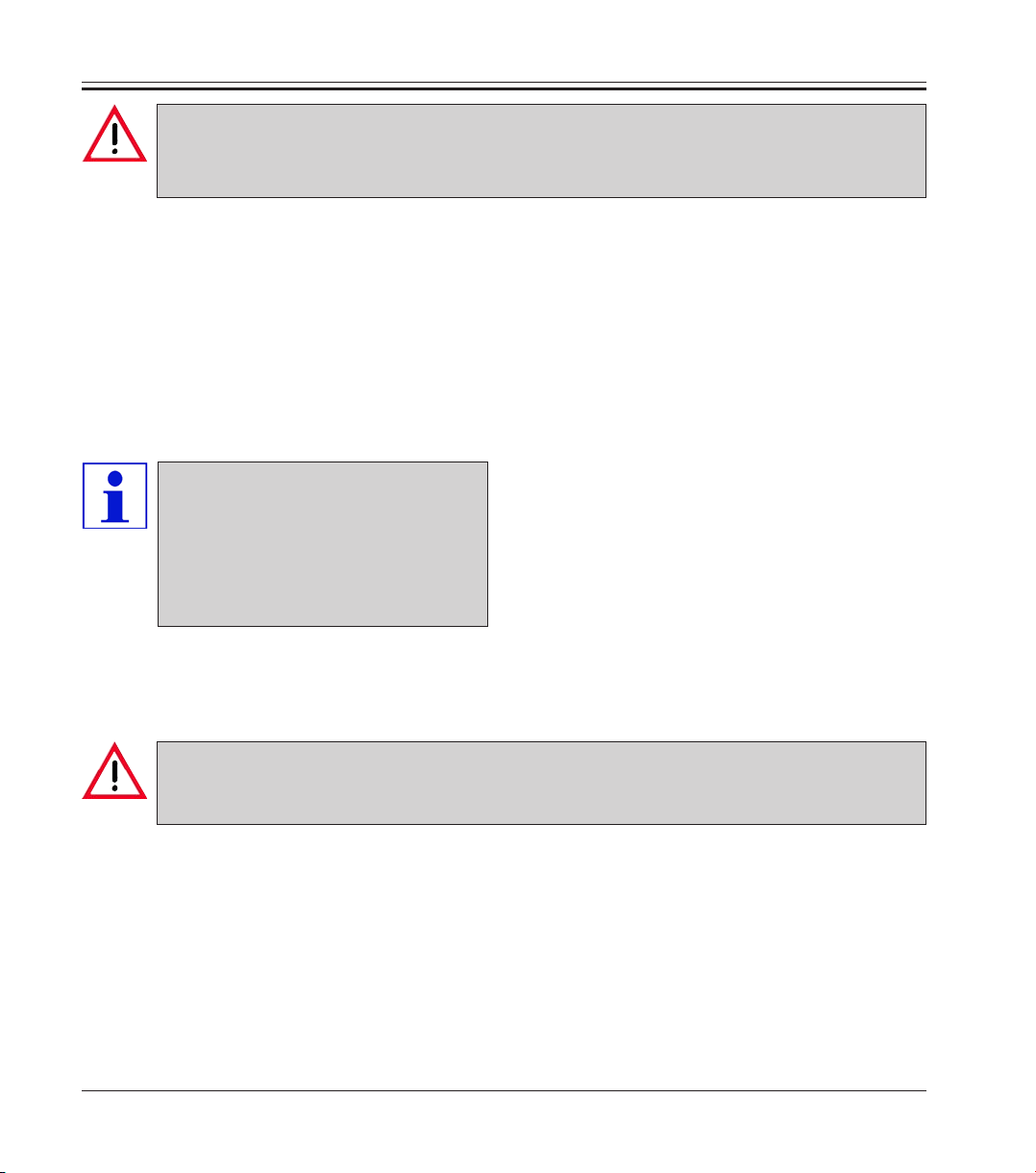
3.4.1 Emergency stop switch
3. Safety
The Leica CM3600 is equipped with an emergency stop switch (1) located
on the chamber surface to the left of the window.
Activating the emergency stop switch
Press the Emergency stop switch (1) to stop the microtome immediately.
Resetting the emergency stop switch.
To reset the emergency stop switch (1) turn it in the direction of the arrow
until it is released upwards back to its original position.
Leica CM3600 – Cryomacrotome
1
21
Page 22
3. Safety
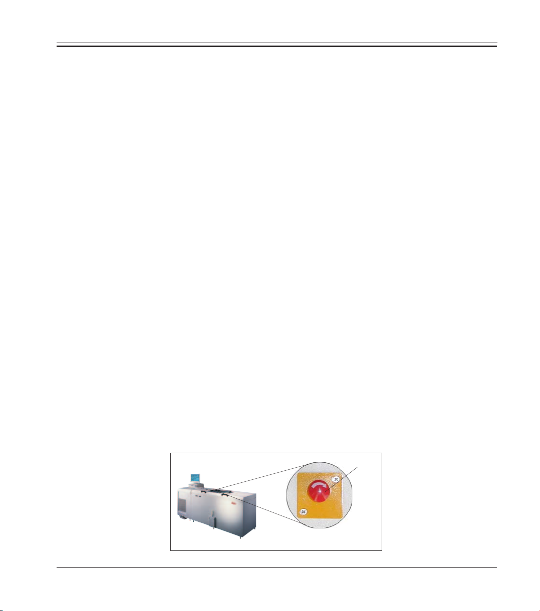
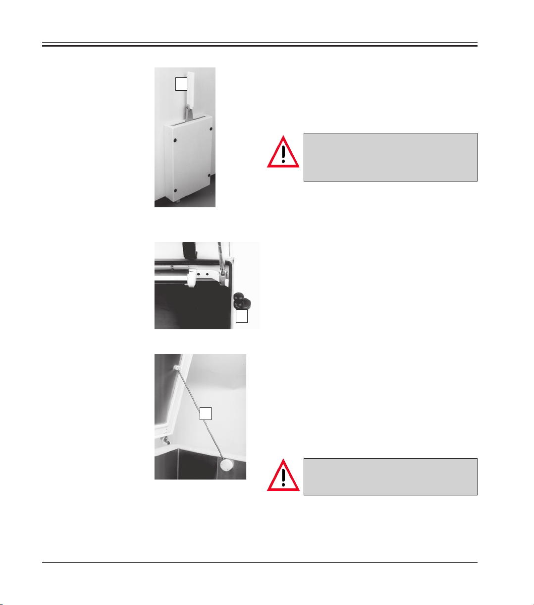
3.4.2 Knee lever
3.4.3 Window
3.4.4 Cryochamber
1
Never leave the instrument unattended when
the knee lever is folded out (1) to prevent the
microtome from being set in motion accidentally.
Always swing the knee lever
upwards before leaving the instrument.
The window is heatable and equipped with a
lock button (2). To open the window, lift lock
button (2) slightly upwards and turn it by 180°.
2
Before opening the large chamber lid, first
close the window and lock with the lock button
(2).
3
When opening the chamber lid, make sure the
lid retainer (3) engages to prevent the chamber
lid from falling.
22
When opening the chamber lid, the
lid retainer must engage.
Instruction manual V 6.0 - 08/2006
Page 23
3.5 Special safety instructions
The safety devices installed in the Leica CM3600 by the manufacturer
only constitute the basis for accident prevention.
Primarily responsible for accident-free operation is above all the institution which owns the instrument and, in addition, the designated personnel
who operates, services or repairs the instrument.
To ensure trouble-free operation of the instrument, make sure to comply
with the following instructions and warnings.
3. Safety
The protective devices on the instrument must neither be
removed nor modified.
Connect the instrument only to a grounded mains power
outlet.
Do not cancel the protective effect of the grounded power
outlet by using extension cords without ground conductor.
Leica CM3600 – Cryomacrotome
Use extreme caution when handling microtome knives and
disposable blades.
Handle knives / blades as per manufacturer‘s directions.
Do not operate the instrument in non explosion-proof rooms.
During instrument setup / installation do not switch the instrument on before being instructed to do so by this manual.
23
Page 24
3. Safety
As you work through the instruction manual, familiarizing
yourself with the instrument, do not yet install a knife or
specimen.
Below you find a summary of all warnings contained in this instruction
manual.
Any use of the instrument not described in this instruction
manual is considered improper.
Always swing the knee lever upwards before leaving the
instrument.
When opening the chamber lid, the lid retainer must engage.
Prior to exchanging the fuse in the socket panel, switch the
instrument mains switch off and unplug the instrument from
mains. Only use fuses of the same type and characteristics as
originally supplied (see chapter 2.2 ‘Technical data’ for fuse
specification).
24
The control PC as well as all peripherals connected to it
(printer, monitor, etc.) are set to an input voltage of 230V/50Hz.
For reasons of compatibility (CE Directives, UL Approval) they
may only be connected to the socket panel of the instrument,
using the connecting cables supplied.
Prior to any work involving the knife, microtome or inside the
cryochamber, activate the emergency stop switch. For further
information, refer to chapter 3.4.1.
Instruction manual V 6.0 - 08/2006
Page 25
3. Safety
Prior to any work involving the knife, microtome or inside the
cryochamber, swing the knee lever upwards.
For any work involving the knife, microtome or inside the
cryochamber always wear special protective gloves.
For reasons of safety and accuracy, the maximum trimming
thickness should not exceed 100 μm per section.
When trimming biological material (particularly bone), section thickness should not exceed 50 μm.
Never try to catch or grab a knife.
Never introduce your hands into the space between specimen
and knife.
Leica CM3600 – Cryomacrotome
Radioactive specimen waste must be disposed of according to
the local radiation safety regulations.
For removing the microtome (approx. 190 kgs) from the
cryochamber, a ceiling crane capable of carrying that weight
should be available.
For safety reasons, we strongly advise you against lifting the
microtome (190 kgs) from the cryochamber without appropriate lifting gear. Do not attempt to lift the microtome from the
chamber manually, even if several persons are there to help.
25
Page 26
4. Site requirements
4.1 Site requirements at place of installation
If possible at all, the room should be air-conditioned.
Relative humidity≤ 60 %.
Room temperature should not exceed 22 °C.
If ambient conditions are not maintained as specified, instrument performance may be negatively affected (lowest specified temperature may not
be reached, frost may accumulate).
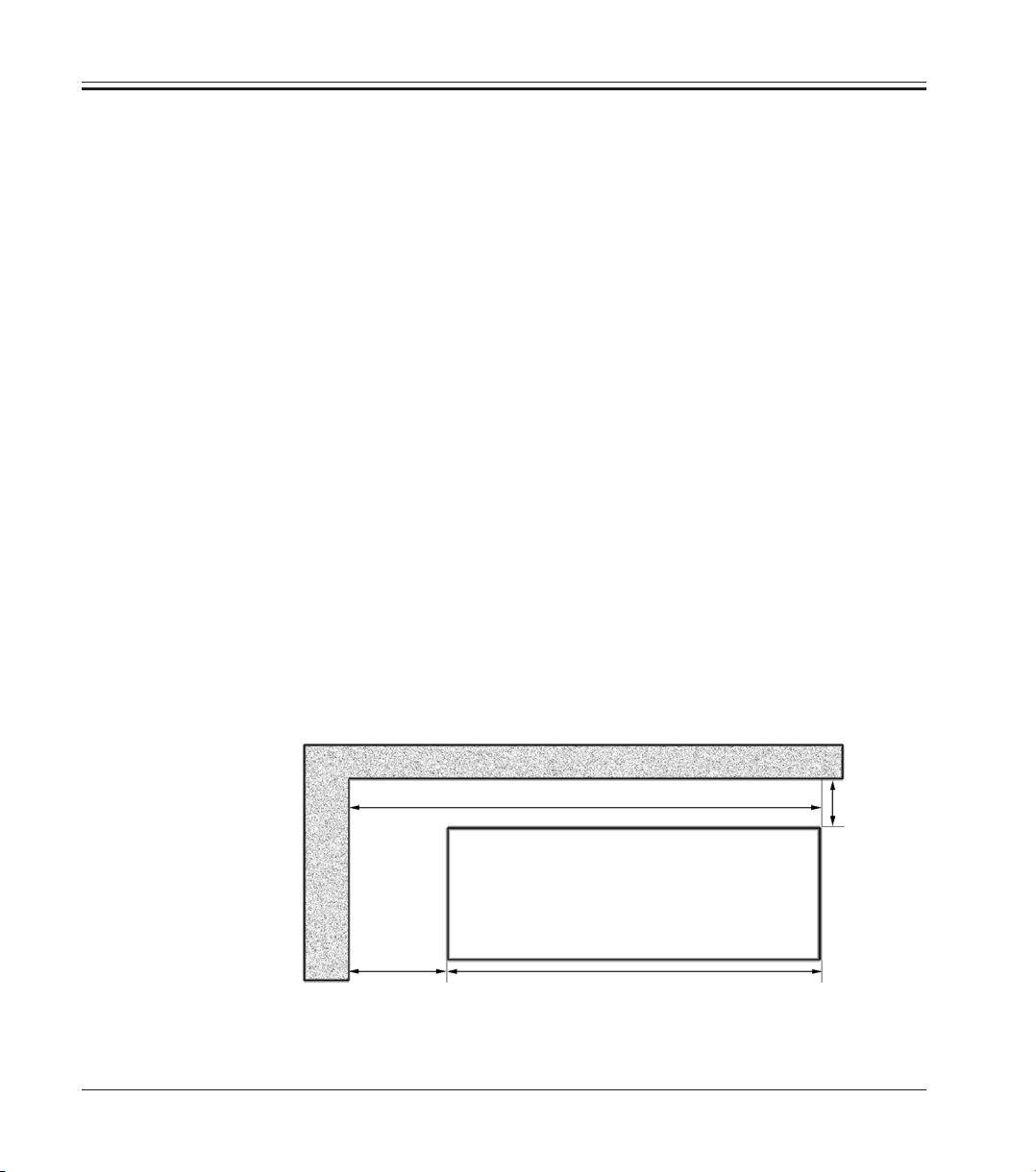
All transportations paths for the Leica CM3600 must at least be 1.5 meters
wide, especially doorways must have that width. 1.5 m is wide enough for
the instrument to pass through the doorway at an angle (if the instrument
can pass straight through the doorway, a width of 95 cm will be sufficient).
The Leica CM3600 has a total length (refrigeration and control unit plus
cryochamber) of 2.7 meters or 2.8 meters including the connecting cables
on the left side of the refrigeration and control unit, i.e. a minimum wall
length of 2.9 meters is required to install the instrument. Ideally the wall
should measure 3.5 meters or more to provide easy access to the left side
of the unit for technical service work. The required minimum distance
between the back panel of the instrument and the wall is 30 cm, the
recommended distance is 50 cm.
26
Installation wall, ideal dimensions (view from above)
ca. 3.5 m
Leica CM3600
ca. 0.8 m
ca. 2.7 m
Instruction manual V 6.0 - 08/2006
0.5 m
Page 27
4.2 Electrical connections
4. Site requirements
For removing the microtome (approx. 190 kgs) from the
cryochamber, a ceiling crane capable of carrying that weight
should be available.
If no ceiling crane is installed yet, we recommend the special
Leica crane „KR-CM3600“.
4.3 Other connections
Country: Europe USA Japan
Installation cord cross section: 2.5 mm
2
2.5 mm
2
2.5 mm
2
Fuse/connection: 16 A/380 V 25 A/208V 25 A/200V
Telephone connection
For remote failure diagnosis, a telephone connection must be available to
hook up the modem. The phone connection must be direct, i.e. must not
be controlled by an additional computer (server).
Compressed air supply
If you want to use the optional extraction system:
Compressed air supply for the extraction system (p = 5 - 8 bar) must be
available.
Leica CM3600 – Cryomacrotome
27
Page 28

5 Installation
5.1 Unpacking and installation
Only duly trained personnel may unpack and install the Leica CM3600.
Please contact your local Leica sales organization for appropriate advice.
5.2 Standard delivery
The standard delivery includes:
• 1 Leica CM3600, consisting of:
• Cabinet
• Refrigeration and control unit
• PC (computer, monitor, keyboard, mouse)
• Microtome 450 C with integrated knife holder
• 1 Disposable blade holder 157 AR
• 1 Dispenser with 10 disposable blades, type H 45 L
• 1 Roll of section collecting tape, type 810
• 1 Roll of section collecting tape, type 4248
• 1 Bottle of low temperature oil PDP 40, 500 ml
• 1 Positioning tool for disposable blade holder
28
• 1 Tool set, consisting of:
• Allen keys, set of 7, in different sizes: 1.5, 2.0, 2.5, 3.0, 4.0, 5.0, 6.0
• Fork wrenches, set of 2, sizes 15 and 17
• 1 Syringe 10 ml with hypodermic needle
• 1 Instruction manual
• 1 Set of manuals for PC
• 1 Pressure plate
• 1 Pair of protective gloves
Please compare the delivered parts carefully with the packing
list, delivery note and with your order.
If you notice any discrepancies, please contact your local
Leica sales office or dealer immediately.
Instruction manual V 6.0 - 08/2006
Page 29
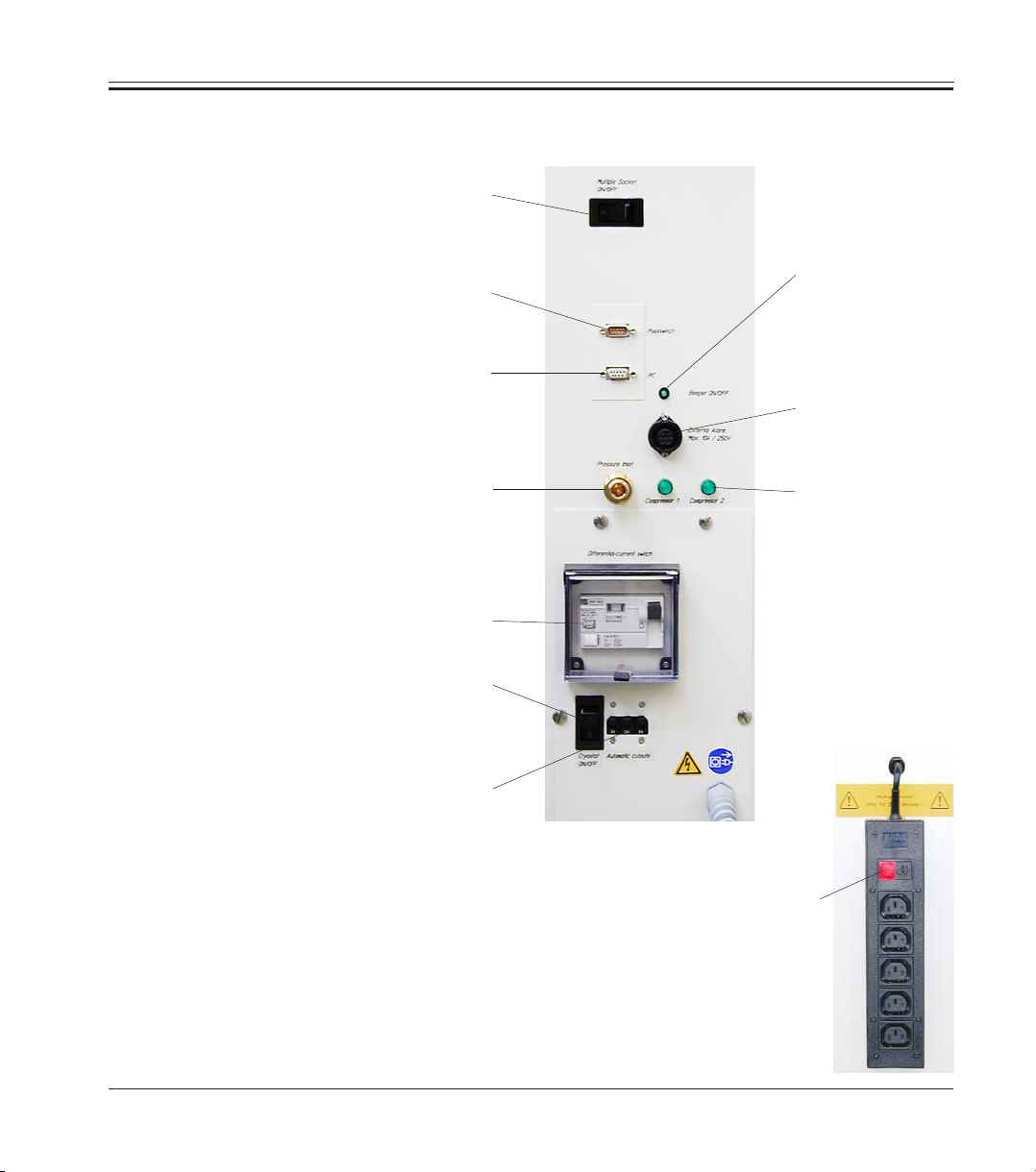
5.3 Port and switch panel
5. Installation
Connecting block
Switch for
socket panel
Interface
RS 232
Connection for
foot switch
Connection for
compressed air
Ground fault circuit
interruption
Mains switch
Automatic
cutout
External
alarm
signal switch
Connection for
external alarm
Control
lamps
Socket panel
Leica CM3600 – Cryomacrotome
Control lamp
29
Page 30

5. Installation
5.3.1 Port and switch functions
Mains switch
Switch in position “0“ - instrument disconnected from mains except for
the socket panel.
Socket panel switch
Control light is on (red), when the socket panel switch is ON.
Foot switch connection
Optionally, a foot switch can be connected for the purpose of section
thickness documentation (GLP).
RS 232 interface
The RS 232 interface links the PC to the PLC.
Switch for external alarm signal
The external alarm (acoustic signal) is triggered, when the
chamber temperature exceeds the selected value. When the temperature
dips back down below the defined threshold, the external alarm is immediately switched off. Loss of mains power supply (instrument switched off
or power failure) will also trigger the external alarm. On return of mains
supply the alarm is automatically switched off.
To activate the external alarm function, press the alarm signal switch.
The green LED in the switch button lights up. To deactivate the external
alarm function, press the alarm signal switch once again. The green LED
in the switch button is extinguished.
30
Connection for external alarm
Forwarding an external alarm.
Compressed air supply
Connection of compressed air hose to extraction unit.
Control lamps
Indicate function of the refrigerating sets.
Instruction manual V 6.0 - 08/2006
Page 31

5.3.2 Fuses
5. Installation
GFCI switch
Protects the entire instrument.
Automatic cutout
Protects the refrigerating sets and all electronic components.
The Leica CM3600 is equipped with the following fuses:
• GFCI switch
• Automatic cutout
• Fuse protecting the mains switch
• Fuse protecting the socket panel
GFCI switch
After the GFCI switch has been activated, it will be in the lower position.
To switch it back on, flip the GFCI switch upwards.
Automatic cutout
After the automatic cutout has been activated, it will be in the lower
position. Flip it upwards to switch it back on.
Leica CM3600 – Cryomacrotome
GFCI switch
Automatic cutout
31
Page 32

5. Installation
Fuse protecting the mains switch
If the mains switch fuse has blown, please call Technical
Service.
S
Fuse protecting the mains
switch
Fuse protecting socket panel
If the socket panel fuse has blown, please proceed as follows:
Prior to exchanging the fuse in the socket panel, switch the
instrument mains switch off and unplug the instrument from
mains. Only use fuses of the same type and characteristics as
originally supplied (see chapter 2.2 ‘Technical data’).
1. Push the fuse carrier inwards with a screw driver and turn the screw
driver approx. one quarter turn to the left.
2. Pull out the fuse carrier.
3. Remove the fuse.
4. Insert a replacement fuse of identical specification.
5 Reinsert the fuse carrier.
6. Push the fuse carrier slightly inwardswith the screw driver and turn it
one quarter turn to the right.
7. Reconnect the instrument to mains and switch back on.
32
Fuse protecting socket panel
Fuse carrier
Instruction manual V 6.0 - 08/2006
Page 33

5.4 PC
5. Installation
The Leica CM3600 is equipped with a commercial PC, monitor, keyboard,
mouse and an internal modem. For further information, please refer to the
manual of the PC.
The control PC as well as all peripherals connected to it
(printer, monitor, etc.) are set to an input voltage of 230V/50Hz.
For reasons of compatibility (CE Directives, UL approval) they
must be connected only to the socket panel of the instrument
(see chapter 5.3 for more details), using the connecting cables
supplied.
Leica CM3600 – Cryomacrotome
33
Page 34

6. Software
6.1 Start and log-in procedure
Requirements:
PC must be on and the Microsoft Windows XP® operating system must
have booted and be ready for service.
Registration mask
Doubleclicking on Icon „CM3600“ starts the application.
34
1. Type the user name in the identification field.
2. Type the correct password in the password field.
3. Click the OK button to complete registration.
After successful registration, the „Main window“ will open. For further
information, refer to chapter 6.4.
After 5 faulty registration attempts, access to the unit will be
denied. Only an Administrator can remove the lock. For further
information, refer to chapter 6.5.2.
Instruction manual V 6.0 - 08/2006
Page 35

6.2 Description of the window elements
The window surface is divided into several areas:
• Title bar
• Tool bar
• Work space
• Status bar
6. Software
Title bar
Tool bar
Work space
Status bar
6.2.1 Title bar
The „Title bar“ displays information on instrument name and software
version number.
6.2.2 Tool bar
The „Tool bar“ provides quick access (via mouse-click) to individual
software functions.
When clicking on an icon, the corresponding window will open up.
Active icons will light up in green.
Leica CM3600 – Cryomacrotome
35
Page 36

6. Software
Icons
Clicking on the icon opens the „Main window“, which also
opens up after completion of the start and log-in procedure.
Clicking on the icon opens the „Parameter settings“ window.
Clicking on the icon opens the „Temperature curve“ window.
Clicking on the icon opens the „Chronological event list“
window.
Clicking on the icon opens the „Alarm list“ window.
Clicking on the icon switches the chamber illumination on or
off. Active icons will light up in yellow.
Clicking on the icon opens the „Section documentation“
window.
36
Clicking on the icon activates the „Photo mode“.
Clicking on the icon creates a printout of the current screen.
Clicking on the icon opens the „Remote inquiry“ window.
Clicking on the icon opens the „Help“ window.
Clicking on the icon opens the „Saves“ window. When activated, the icon will light up in green.
Instruction manual V 6.0 - 08/2006
Page 37

6. Software
Clicking on the icon opens the „Label printing“ window. When
activated, the icon will light up in green.
Clicking on the icon activates the „Foot switch“. When activated, the icon will light up in green and the current sectioning
data will be saved.
The ‘Stop’ icon appears immediately when the emergency stop
switch is pressed - it will be blinking in red color. The instrument will be inoperational until the operator acknowledges the
corresponding error message in the „Alarm list“ window. For
further information, refer to chapter 6.8.
Clicking on the „Log off“ icon logs off the user currently logged
on. Clicking again reopens the registration mask for Log-in.
Clicking on „Quit“ closes the application.
Clicking on the icon opens a window providing information on
software version number, date, copyright and serial number of
the application.
6.2.3 Work space
In the work space area all control entries and settings are made. Display
format may vary depending on the icon selected in the tool bar.
6.2.4 Information bar
The information bar displays the following information:
• the currently registered user,
• instrument name and software version number,
• number of sections carried out so far,
• name of laboratory.
Leica CM3600 – Cryomacrotome
37
Page 38

6. Software
6.3 Initialization
To be able to work with the instrument, after completion of the
start and log-in procedure the microtome must be initialized.
For initialization, proceed as follows:
1. In the „Main window“, click on the INIT button blinking in yellow color
(in ‘Mode’ field).
The „Safety check - initialization“ window will open up.
38
2. Check wheter you can confirm each safety query - if not, carry out the
required actions. Subsequently, confirm each safety query by mouse
click on the corresponding check box.
3. Having confirmed all safety queries, click on OK.
The microtome will then be initialized:
• The knife holder moves to the uppermost position.
• The microtome sledge moves to the end positions on the right and left.
Instruction manual V 6.0 - 08/2006
Page 39

6. Software
Once initialization has been started, it can only be interrupted
by pressing the emergency stop switch. For further information, refer to chapter 3.4.1.
After the initialization procedure has been completed, the color of the
INIT button will first change from yellow to green and after a few seconds, the caption on the button will change from INIT to AUTOMATIC.
The microtome is now ready for service. For further information, refer to
chapter 6.4.9.
Leica CM3600 – Cryomacrotome
39
Page 40

6. Software
6.4 Main window
The main window either opens up automatically after completion of the start and log-in procedure or by clicking on the
„Main window“ icon.
40
The work space of the main window is divided as follows:
• Chamber temperature
• Time
• Automatic defrost
• Automatic dehydration
• Knife movement
• Extraction
• Section program
• Sledge speed
• Mode (of operation)
• Cutting window
Instruction manual V 6.0 - 08/2006
Page 41

6.4.1 Chamber temperature
Indication of set or actual chamber temperature.
See chapter 6.5.1 ‘Parameter settings’ on how to set the chamber temperature.
6.4.2 Time
Indication of real time and date.
See chapter 6.5.1 ‘Parameter settings’ on how to set the time.
6.4.3 Automatic defrost cycle
6. Software
Indication of start time of 1st or 2nd automatic defrost cycle.
See chapter 6.5.1 ‘Parameter settings’ on how to set the defrost cycle.
Manual defrost button
Clicking on this button immediately starts a defrost cycle. During the
defrost cycle, the button blinks in yellow color. Clicking on the button
once more aborts the defrost cycle.
Leica CM3600 – Cryomacrotome
41
Page 42

6. Software
6.4.4 Automatic dehydration
Indication of start time, start date and duration of the automatic dehydration.
See chapter 6.5.1 Parameter settings on how to set the automatic dehydration parameters.
MANUAL DEHYDRATION button
Clicking on this button immediately starts a dehydration cycle. Clicking
on this button once more, stops dehydration. When activated, the button
blinks in yellow color.
If the temperature is to be decreased during automatic dehydration, this
must be specified in the „Parameter settings“ window. For further information, refer to chapter 6.5.1.
6.4.5 Knife movement
42
Indication of section and retraction thickness. Actual indicates the
current position of the knife holder. Set indicates the desired position of
the knife holder.
Instruction manual V 6.0 - 08/2006
Page 43

6. Software
The red „Retraction“ caption is displayed only during the return stroke of
the sledge.
The ‘Knife movement’ icons can be activated only in MANUAL
Mode. For further information, see chapter 6.4.9.
The entry limit for actual and set position may vary between 70
- 200 μm, depending on the instrument version. The standard
version is shipped with a limit of 70 μm.
To modify any of the settings, mouse-click on the corresponding icon.
Entries are completed by pressing the ENTER key.
KNIFE UP button on the left
Clicking on this icon moves the knife holder upwards for a short while.
If you click on and hold this icon, the knife holder will continue to move
upward until the left mouse button is released. While active, the icon
blinks in yellow color.
KNIFE DOWN button on the left
Clicking on this icon moves the knife holder downwards for a short while.
If you click on and hold this icon, the knife holder will continue to move
downward until the left mouse button is released. While active, the icon
blinks in yellow color.
KNIFE UP button on the right
Clicking on the KNIFE UP button on the right activates the corresponding
function. The knife holder will move upwards until reaching the upper
limit position. To stop the knife movement, click on the button once more.
When activated, the button will light up in green.
Leica CM3600 – Cryomacrotome
43
Page 44

6. Software
KNIFE DOWN button on the right
Clicking on this button moves the knife holder fast downwards for a short
while. If you click on and hold this button, the knife holder will continue to
move downward until the left mouse button is released. While active, the
button blinks in yellow color.
PRESELECTION button
Clicking on this button activates the ‘Set position’ display. Click on the
displayed value to change the setting. While active, the icon lights up in
green color.
START/STOP button
The START/STOP button can be activated only when the PRESELECTION
button is active. Clicking on START/STOP moves the knife holder so the
selected set position. When activated, this button will light up in green.
Clicking on this button once more stops the knife holder.
Once the knife holder has reached the upper limit position,
both KNIFE UP buttons blink in green color.
Once the knife holder has reached the lower limit position,
both KNIFE DOWN buttons blink in yellow color.
44
Once the set position has been reached, it can only be left by
activating the knee lever. For further information, refer to
chapter 3.4.2. A corresponding message will appear on the
screen.
Instruction manual V 6.0 - 08/2006
Page 45

6.4.6 Extraction system
6.4.7 Sectioning program
6. Software
The extraction function can only be activated when an extraction unit is connected to the instrument. For further information, refer to chapter 9.1.
Button EXTRACTION ON/OFF in continuous mode
Clicking on this button activates or deactivates continuous extraction.
When activated, the button will light up in green.
Button EXTRACTION ON/OFF in intermittent mode
Clicking on this button activates or deactivates intermittent extraction.
When activated, the button will light up in green.
Indication of set or actual number of sections.
To modify any of the settings, mouse-click on the corresponding button.
Entries are completed by pressing the ENTER key.
PROGRAM button
Clicking on this button activates the set value display.
Leica CM3600 – Cryomacrotome
The buttons can be activated only in AUTOMATIC Mode.
Clicking on the START/STOP button located in the ‘Mode’ field
starts or stops the sectioning program. For further information,
refer to chapter 6.4.9.
45
Page 46

6. Software
6.4.8 Sledge speed
Click on the activated set value field to modify the setting.
PAUSE button
Clicking on this button stops the sectioning program. Clicking on the
button once more restarts the sectioning program, resuming the current
section where if was left off.
Indication of current sectioning or return stroke speed in mm/s (millimeters per second). To modify any of the settings, click on the corresponding value.
46
The graphic display is active only while sectioning is in progress. The
currently selected sectioning and return stroke speed are displayed via a
green bar on a scale from 0 - 80 mm/s.
Instruction manual V 6.0 - 08/2006
Page 47

6.4.9 Mode of operation
6. Software
To be able to work with the instrument, after completion of the start and
log-in procedure the microtome must be initialized. For further information, refer to chapter 6.3.
Buttons prior to initialization
Buttons after initialization
INIT button
Clicking on INIT opens the ‘Initialization’ window. For further information,
refer to chapter 6.3. Prior to initialization, the button blinks in yellow color.
After the initialization procedure has been completed, the color of the
INIT button will change from yellow to green. After a few seconds, the
caption on the button will change from INIT to AUTOMATIC.
AUTOMATIC button
Clicking on this button switches the instrument to automatic mode. When
activated, the button will light up in green.
MANUAL button
Clicking on this button switches the instrument to manual mode. When
activated, the button will light up in green.
START/STOP button
This button can only be activated in automatic mode, where it starts or
stops the sectioning program. When activated the START/STOP and
AUTOMATIC buttons will light up in green.
Leica CM3600 – Cryomacrotome
47
Page 48

6. Software
6.4.10 Cutting window
Indication of the left and right block edge, graphically displayed by blue
lines. They indicate the maximum horizontal stroke of the microtome
sledge on a scale from 0 - 500 mm.
Indication of the actual position of the microtome sledge. The sledge
position is graphically displayed by the green line.
To modify any of the settings, mouse-click on the ‘Actual position’ indication.
Clicking on the icons on the left an right of the scale lets you
adjust the left and/or right half of the block to the actual microtome sledge position indicated.
48
LEFT BLOCK EDGE
Clicking on the inscription LEFT BLOCK EDGE opens up an entry window.
Select the left limit position to where the microtome sledge can move on a
scale from 0 - 500 mm.
RIGHT BLOCK EDGE
Clicking on the inscription RIGHT BLOCK EDGE opens up an entry window. Select the right limit position to where the microtome sledge can
move on a scale from 0 - 450 mm.
Instruction manual V 6.0 - 08/2006
Page 49

6.5 Parameter settings
6. Software
Click on „Parameter settings“ to open the corresponding
window.
The work space of the parameter settings window is divided as follows:
• Parameter setting
• Password list
• Configuration
• Reference voltages
• Language selection
• Initialization
Leica CM3600 – Cryomacrotome
49
Page 50

6. Software
6.5.1 Parameter setting
Set chamber temperature
Click on this indication to change the currently selected value. Temperature values from -30 to +1° C can be selected.
Alarm temperature
Click on this indication to change the currently selected value. Temperature values from -25 to -5° C can be selected.
50
The alarm temperature should not be too close to the set
chamber temperature. If the alarm temperature is too close to
the set chamber temperature, an alarm can be triggered
simply when working with the instrument during a prolonged
period of time or during the daily defrost cycle.
A temperature difference of approx. 5 K (Kelvin) is recommended.
Instruction manual V 6.0 - 08/2006
Page 51

6. Software
Time and date
Indication of time and date. Clicking on this indication opens the dialog
box „System time“.
Clicking on individual parameters (day, month, year,
hour or minutes) the corresponding setting can be changed.
Click OK to confirm.
Start time 1 defrost
Indication of start time of the 1st automatic defrost cycle.
Clicking on this indication opens the dialog box „defrost time“.1
Click on individual parameters (hours or minutes) to change the corresponding settings. Click OK to confirm.
Start time 2 defrost
Indication of start time of the 2nd automatic defrost cycle. Clicking on this
indication opens the dialog box „defrost time“.2
Click on individual parameters (hours or minutes) to change the corresponding settings. Click on OK to confirm.
Button active/inactive
Clicking on this button activates or deactivates the 2nd automatic defrost
cycle.
Leica CM3600 – Cryomacrotome
51
Page 52

6. Software
Dehydration date
Dehydration start time
Dehydration duration
Indication of start date and time, and duration of the automatic dehydration cycle. Clicking on one of the parameters opens the dialog box „Dehydration time“.
Click on individual parameters (day, month, year, hour or minutes) to
change the corresponding settings.
The desired duration of the dehydration procedure can be selected in the
duration field. Values from 1 - 48 hours can be selected. Click OK to
confirm.
To speed up the dehydration procedure, the dehydration
cryochamber temperature can be lowered. This can be done
via the ‘Dehydration T-reduction’ indication.
52
Dehydration T-reduction
Indication of temperature reduction for dehydration. Click on this indication to change the currently selected value. Values from 0 - 20 K can be
selected.
Section thickness
Indication of section thickness. Click on this indication to change the
currently selected value. Values from 0 - 200 μm can be selected.
Retraction value
Indication of the currently selected retraction value. Click on this indication to change the currently selected value. Values from
50 - 250 μm can be selected.
Instruction manual V 6.0 - 08/2006
Page 53

6. Software
Cutting speed
Return speed
Indication of cutting and return speed. Click on one of the indications to
change the currently selected value. Values from 0 - 80 mm/sec can be
selected.
Left block edge
Right block edge
Indication of left and right block edge. Click on the individual indication to
change the currently selected value. Values from 0 - 500 mm can be
selected. For further information, refer to chapter 6.4.10.
Photo position dwelling time
Photo position triggering time
Indication of photo position dwell and triggering time. Click on the individual indication to change the currently selected value. Values from 0 255 seconds can be selected. For further information, refer to chapter
6.11.
EDIT button in the password list
Clicking on this button opens the „User configuration’ window. For further
information, refer to chapter 6.5.2.
EDIT button in the configuration field
Clicking on this button opens the „Configuration’ window. For further
information, refer to chapter 6.5.3.
Leica CM3600 – Cryomacrotome
53
Page 54

6. Software
6.5.2 Password list
To access the ‘User configuration’, the registered user must be
an administrator.
The „user configuration“ indication consists of the following columns:
54
• No.
Indication of the program-controlled running number.
• Active
Indication of status of the user selected. Active users are displayed
with an „X“.
• User name
Indication of the user name, which is introduced in the identification
field during the start and log-in procedure.
• Full name
Indication of full user name.
• User rights
Indication of the corresponding access right. The administrator has
full access to all application functions. Users have only limited access.
Instruction manual V 6.0 - 08/2006
Page 55

6. Software
CLOSE button
Clicking on this button closes the ‘User configuration’ window.
Doubleclicking on a line in the configuration indication opens
the dialog box „User configuration“.
In the „user configuration“ dialog box the following settings can be
selected:
• No.
Indication of the running number. No changes can be made in this
field.
• Active
• User name
• Full name
Leica CM3600 – Cryomacrotome
Clicking on the check box sets the user status to „active“. Only after
this step can a user successfully register via the start and log-in
procedure.
Enter the desired user name. A maximum of 10 characters (numerical
or alphanumerical) can be entered.
Enter full first and last name of user.
55
Page 56

6. Software
• Access rights
Click on the USER RIGHTS line to open a drop down menu.
User property ‘Administrator’ or ‘User’ can be selected.
Administrators have full access to all application functions.
Users do not have access to the password list and to the
configuration parameters in the “Parameter settings“ window.
• Identification
Type in the identification which is needed for the start and log-in
procedure.
• Confirm identification
Repeat the identification.
DELETE button
Clicking on this button deletes the selected user without any prior safety
query.
OK button
Clicking on this button saves the the entries and closes the „User configuration“ dialog box.
56
CANCEL button
Clicking on this button closes the „User configuration’ dialog box. Any
changes made are not saved.
Instruction manual V 6.0 - 08/2006
Page 57

6.5.3 Configuration
6. Software
To access ‘Configuration’, the registered user must be an
administrator.
The „Configuration“ window contains the following tabs:
• Text main study
• Text substudy
• Measured values
• General
• Labels
• Comments
OK button
Clicking on this button saves the entries and closes the „Configuration“
dialog box.
CANCEL button
Clicking on this button closes the „Configuration“ window without saving
any of the changes made.
Leica CM3600 – Cryomacrotome
57
Page 58

6. Software
Tabs „Text main study“ and „Text substudy“
The structure of the two tabs is identical. A header and 7 freely selectable
comments for each main and/or substudy can be defined.
The text entered into the 8 entry fields is copied into the dialog box for
creating main and substudies. Each individual text can consist of up to 30
characters. For the configuration of a main or substudy see chapter 6.10.
58
Tab „Measured values“
For selecting the measured values to be displayed in the ‘section documentation’ window after having selected a main or substudy.
Instruction manual V 6.0 - 08/2006
Page 59

6. Software
For the configuration of a main or substudy see chapter 6.10.
The following measured values can be selected:
• Set chamber temperature
• Actual chamber temperature
• Alarm temperature
• Set section thickness
• Actual section thickness
• Knife holder position
• Dehydration
• Comment
Tab „General“
The „General“ tab contains the following entry fields:
• Company/lab
• Printer for label printing
• Font size
• Printer for protocoling
• Printer for hardcopies
• Path for export
• Millitron
• Activate millitron
Leica CM3600 – Cryomacrotome
59
Page 60

6. Software
Company/lab
Enter the name of the company or the laboratory. The name will be
displayed in the „information bar“, on the right side, see chapter 6.2.4.
Printer for label printing
Clicking on this line opens a drop down menu. If a printer for label printing
is connected, it can be selected in this menu.
Font size
Clicking on this line opens a drop down menu. Here you can select the
desired font size for the labels.
Printer for protocoling
Clicking on this line opens a drop down menu. If a printer for protocoling
is connected, it can be selected in this menu.
Printer for hardcopies
Clicking on this line opens a drop down menu. If a printer for hardcopies
is connected, it can be selected in this menu.
If no printer can be selected, a printer must be retroinstalled in
the PC‘s Microsoft Windows XP® operating system.
60
Path for export
Clicking on the „Export path“ symbol opens the dialog box
„Path for export“.
Here you can select a directory where you want to save the
data.
Instruction manual V 6.0 - 08/2006
Page 61

6. Software
Die export file is filed as a text file and according to the export path
selected.
Millitron
Provided an external Millitron measuring device is connected to the PC,
the corresponding serial connecting port can be selected via the drop
down menu.
Activating the millitron
Clicking on the check box activates the external millitron measuring
device.
‘Labels’ tab
In the label tab you can enter the text for the labels. For further information, refer to chapter 6.16.
9 lines of 50 characters each can be entered. Lines where no characters
have been entered are printed as empty lines.
Clicking on the BOLD check box in the corresponding line activates bold
print.
Predefined variables commencing with the special character „@“,
represent specific information on the labels. See following page for
details.
Für die Ausgabe von vordefinierten Variablen, die mit dem Sonderzeichen
Leica CM3600 – Cryomacrotome
„@“ beginnen, können bestimmte Informationen im Etikettendruck ausgegeben
61
Page 62

6. Software
The following information can be represented as variables:
@a Main study - name
@b Main study - comment line 1
@c Main study - comment line 2
@d Current date (date)
@e Main study - comment line 3
@f Main study - comment line 4
@g Main study - comment line 5
@h Main study - comment line 6
@i Main study - comment line 7
@j Substudy - name
@k Substudy - comment line 1
@l Substudy - comment line 2
@mSubstudy -comment line 3
@n Substudy - comment line 4
@o Substudy - comment line 5
@p Substudy - comment line 6
@q Substudy - comment line 7
@t Current time (time)
@0 Measured value - no. of section
@1 Measured value - date of section
@2 Measured value - time of section
@3 Measured value - set chamber temperature
@4 Measured value - actual chamber temperature
@5 Measured value - alarm temperature (yes/no)
@6 Measured value - set section thickness
@7 Measured value - actual section thickness
@8 Measured value - knife holder position
@9 Measured value - dehydration (on/off)
62
Repeating the variable wild card defines the length of the variable. The
variable wild card @333 will display 4 characters for ‘set chamber temperature’, as ‘@’ already represents one character. Text variables are
always printed left-justified, numbers right-justified.
Instruction manual V 6.0 - 08/2006
Page 63

6. Software
„Comments“ tab
Frequently used comments can be entered into this tab.
Button NEW
Clicking on this indication opens the dialog box ‘Comment on section’
Here you can enter a comment on a section.
Clicking on OK saves the entry and closes the window. Clicking on Cancel
closes the ‘Comment on section’ dialog box. Any entry made is not
saved.
CHANGE button
Clicking on this indication opens the dialog box ‘Comment on section’. The
existing entry can be changed.
DELETE button
Clicking on this indication opens a safety query dialog. If the safety query
is confirmed by clicking on OK, the comment will be permanently deleted.
Leica CM3600 – Cryomacrotome
63
Page 64

6. Software
6.5.4 Reference voltages
6.5.5 Language selection
Indication of the current reference voltage in Volt.
Buttons 1 to 8
Clicking on these buttons changes the reference voltage. The individual
reference voltage values are predefined and cannot be changed. The
display will read the new selected value. Activated buttons will light up in
green.
The flag buttons indicate the languages that can be selected. Clicking on
one of the flag symbols changes the user interface to the corresponding
language.
6.5.6 Initialization
64
Clicking on EXECUTE in the initialization field opens the „Main window“
and the INIT buton reappears in the ‘Mode of operation’ field.
Clicking on INIT opens the dialog box „Safety check - initialization“. For
further information, refer to chapter 6.3.
Instruction manual V 6.0 - 08/2006
Page 65

6.6 Temperature curves
The window contains the following window panes:
• Work space
• Diagram
6. Software
Click on the temperature curve symbol to open the corresponding window.
Work space
Diagram
Leica CM3600 – Cryomacrotome
The „Temperature curves“ window is only for failure analysis
by Leica Service engineers.
65
Page 66

6. Software
6.6.1 Work space
REFRESH button
Clicking on this button updates the diagram display.
RULER button
If you click on this button, a ruler will be displayed in the diagram. Use
the mouse cursor to move ruler to a certain measuring value position in
order to read the measured value more exactly.
PRINT button
Clicking on this button creates a screen printout of the current diagram
display.
REZOOM button
Clicking on this button resets the diagram display back to how it was.
START and STOP buttons
Clicking on one of these buttons starts or stops the recording of measured values in the diagram.
66
Buttons <<< and >>>
Clicking on one of these buttons starts a forward or backward scroll in
the diagram.
Instruction manual V 6.0 - 08/2006
Page 67

6. Software
Clicking on one of the check boxes in the work space, the 8 temperature
sensors of the instrument can be displayed individually in the diagram.
The font color of the check boxes helps to identify the corresponding
measured values in the diagram, which are displayed in the same color.
The following check boxes can be activated / deactivated via a mouse
click:
• T1 to,
• T2 to 2,
• T3 tv1,
• T4 tv Head II,
• T5 tv2,I,
• T6 tv2,II,
• T7 tHg2,
• T8 Box.
Leica CM3600 – Cryomacrotome
67
Page 68

6. Software
6.6.2 Diagram
The diagram indicates the following:
• Temperature in degree centigrade on the y-axis
• Time and date on the x-axis
• Graphical representation of the 8 temperature measuring points in the
instrument by colored lines
68
The diagram can be enlarged as follows:
1. Within the diagram, click and hold the left mouse button.
2. With the mouse, create a zoom box on the area to be enlarged by
dragging the mouse cursor to the right and downwards at the same
time.
3. Release the left mouse button.
The selected diagram zoom box is enlarged. All measured values activated via the check boxes in the work space are displayed.
Instruction manual V 6.0 - 08/2006
Page 69

6.7 Chronological event list
The events list is a table displaying the events chronologically, in order of
date and time. In this list all events concerning the program are saved.
6. Software
Click on „Event list“ to open the corresponding window.
Work space
Event table
The work space is divided up as follows:
• Work space
• Event table
Leica CM3600 – Cryomacrotome
69
Page 70

6. Software
6.7.1 Work space
FILTER button
Clicking on this indication opens the dialog box „Filter“
Here you can define a time filter limiting the event table indication to one
day, one week or one month.
To set a filter, proceed as follows:
70
1. Click on one of the check boxes DAY, WEEK or MONTH to define the
desired time interval.
2. In the calendar field, select the desired start day for the event information. For this purpose, you can also use the two navigation buttons on
the left and right of the ‘Month’ header.
In the „Time filter“ field you can now see the start time (left) and end time
(right) of the selected time interval.
You can set an additional filter in the „Text filter“ field.
Click on OK to close the dialog box and display the desired alarm messages in the events list.
Click on CANCEL to close the window without changing any of the
changes made.
Instruction manual V 6.0 - 08/2006
Page 71

6. Software
Comment
Clicking on an event in the events list activates the „Comment“ field. You
can enter a comment regarding the selected event. After confirmation
with the ENTER key, the note will be displayed in the event table.
Number
Number of events displayed in the events list.
Print button
Clicking on this button creates a screen printout of the current display.
Export file button
Click on this button to export the events table into a text file.
Leica CM3600 – Cryomacrotome
71
Page 72

6. Software
6.7.2 Event table
The table is divided into the following columns:
• Date/time
Date and time of the events.
72
• User
Name of the user who was logged in when the event occurred.
• Message
Event messages (short description of event).
• Comment
Comments on the events. For further information, refer to chapter 6.7.1.
Individual events messages will be displayed on the events
list for a maximum of 90 days from the date when the event
occurred. After that, the data will be saved into a text file.
Instruction manual V 6.0 - 08/2006
Page 73

6.8 Alarm list
6. Software
Click on the „Alarm list“ symbol to open the corresponding
window.
Work space
Event table
Chronological display of the alarm list as a table, in order of date and
time. In this list, all events concerning the program are saved.
The window contains the following window panes:
• Work space
• Event table
Leica CM3600 – Cryomacrotome
73
Page 74

6. Software
6.8.1 Work space
In the work space the following parameters can be selected:
FILTER button
Clicking on this indication opens the dialog box „Filter“
For further information, refer to chapter 6.7.1.
Comment
Clicking on an event in the alarm list activates the ‘Comment’ field. You
can enter a comment regarding the selected event. After confirmation
with the ENTER button, the note will be displayed in the event table.
Number
Quantity of alarm messages displayed in the alarm list.
CONFIRM button
By clicking on this button the currently registered user confirms the alarm
message previously selected in the alarm list.
74
PRINT button
Clicking on this button creates a screen printout of the current indication.
EXPORT FILE button
Click on this button to export the alarm list into a text file.
Instruction manual V 6.0 - 08/2006
Page 75

6.8.2 Event table
6. Software
The table is divided into the following columns:
• Occurred
Indication of date and time when the alarm started
• Cleared
• Confirmed
• User
• Message
• Comment
Leica CM3600 – Cryomacrotome
Indication of date and time when the alarm stopped
Indication of date and time when the registered user confirmed the
alarm message. For further information, refer to chapter 6.8.1.
Name of the user who confirmed the alarm.
Indication of alarm messages.
Indication of the comment made on the corresponding alarm message.
75
Page 76

6. Software
6.8.3 Error codes: meaning and troubleshooting
Error code Error message Trouble shooting
Error 01
Error 02
Error 03
Error 04
Error 05
Error 06
Error 07
Knife holder - limit position exceeded.
Limit position of sledge exceeded
Chamber - Alarm temperature exceeded
Power failure
Data transfer failed
(happens rather frequently subsequent to a power failure)
Emergency stop activated
• Re-initialize instrument. If the problem recurs, call Technical Service.
• Re-initialize instrument. If the problem recurs, call Technical Service.
• Check whether there has been a power
failure!
• Check the selected alarm temperature value. It must differ at least 5 K from the
chamber temperature selected.
• Check the cable connection between PC
and control unit.
• If problem recurs, call Technical Service
• Not defined
• Deactivate emergency switch
Error 08
Error 09
Error 10
Error 11
76
Stepper motor - step error
Refrigerating system – pressure exceeded
Flap limit switch malfunction
Call Technical Service
• Call Technical Service.
• Check the air circulation between the condenser and the control unit.
• Check the distance of the instrument to the
wall (at least 50 cm)!
• If problem recurs, call Technical Service
• Re-initialize instrument. If the problem recurs, call Technical Service
• Call Technical Service.
Instruction manual V 6.0 - 08/2006
Page 77

6.9 Chamber illumination
6.10 Section documentation
6. Software
Click on the symbol to switch on the illumination of the
cryochamber. Another mouse click will switch the chamber
illumination back off. Active icons will light up in yellow.
Click on the ‘Section documentation’ symbol to open the
corresponding window.
Tree
diagram
Studies protocol
The window contains the following window panes:
• Tree diagram
• Protocol of studies
• Event table
Leica CM3600 – Cryomacrotome
Event table
77
Page 78

6. Software
6.10.1 Tree diagram
Indication of all main studies or substudies in a tree diagram. For navigation purposes, click on the preceding plus or minus sign.
The different study types are identified by the preceding colored folder
symbols:
78
• Yellow folder symbol
Main studies (several).
• Green folder symbol
Main study.
• Blue folder symbol
Substudy.
• Yellow folder symbol „saved“
Main studies (several).
If you click on a study, the studies protocol and the events table will be
displayed on the right. For further information, refer to chapter 6.10.2.
Instruction manual V 6.0 - 08/2006
Page 79

6.10.2 Studies protocol
6. Software
By clicking on a main study in the tree diagram, the following indication
will be displayed in the „Studies protocol“ area:
The table is divided into the following columns:
• No.
Running number automatically allocated by the application.
• Date
Date when the main study was created.
• Name of main study
Name of main study.
To create a new main study or substudy proceed as follows:
1. Right-mouse-click on a spot anywhere in the upper table. A context
2. Select NEW. A dialog box for a new main study or substudy will open
3. Insert the name of the new main or substudy.
4. Press ENTER to confirm your entry and to close the dialog box.
Leica CM3600 – Cryomacrotome
menu will open up.
up.
79
Page 80

6. Software
When clicking on an existing substudy in the tree diagram the following
indication will be displayed in the „studies protocol“ area:
The table is divided up as follows:
• No.
Indication of the running number automatically allocated by the
application, in the order of date of creation of the main study.
• Date/time
Date and time when the section was made
• T-set
Set temperature at the time the section was made
80
• T-actual
Actual temperature at the time the section was made
• T-error
Alarm temperature at the time the section was made
• Set section thickness
Set section thickness at the time the section was made
• Actual section thickness
Actual section thickness at the time the section was made
• Dehydration,
Time when dehydration started / finished.
Instruction manual V 6.0 - 08/2006
Page 81

• Comment
Comments can be entered by the user
• Knife holder position,
Knife holder position at the time the section was made
6. Software
Leica CM3600 – Cryomacrotome
81
Page 82

6. Software
6.10.3 Event table
If you click on a main or substudy in the tree diagram, the following
indication will be displayed in the „Event table“:
The table is divided into the following columns:
• No.
Indication of the running event number automatically allocated by the
application.
• Date/time
Indication of date or time when the event occurred.
• User
Indication of the user who was logged in when the event occurred.
82
• Event
Indication of the event message.
Red: procedure stopped
Green: procedure started
Black: parameter modified (e.g. section thickness, sledge speed)
Instruction manual V 6.0 - 08/2006
Page 83

6.11 Photo mode
6. Software
Clicking on the photo symbol activates or deactivates the
„Photo mode“ and moves the microtome sledge to the mechanical limit stop. When active, the symbol will light up in
green.
The photo mode enables you to position the specimen or rather the
microtome sledge exactly for photos to be taken after each section.
In „Parameter settings“ the „Photo position dwell time“ and the „Photo
position triggering time“ can be selected.
Photo position dwelling time
To define how long the microtome sledge will remain stopped in the
camera position.
Photo position triggering time
Time until the camera will actually take the photo.
For further information, refer to chapter 6.5.1.
6.12 Screen printout
Leica CM3600 – Cryomacrotome
Clicking on the ‘Screen printout’ symbol creates a printout of
the current screen on a defined printer. For further information,
refer to chapter 6.5.3.
83
Page 84

6. Software
6.13 Remote inquiry
Clicking on the „Remote inquiry“ symbol opens the dialog box
‘Safety check - initialization’.
Carry out the required safety query and subsequently confirm each safety
query by mouse click on the corresponding check box. Having confirmed
all safety queries, click on OK.
84
The pcAnywhere application will be started. The pcAnywhere window
opens up.
Note:
The latest pcAnywhere version will
always be displayed.
The control PC of the CM3600 is equipped with a modem enabling Leica
Service Support in case of an instrument malfunction to access directly
the control software. The modem connection will be set up by the
pcAnywhere software installed on the PC.
Instruction manual V 6.0 - 08/2006
Page 85

6. Software
To establish a connection proceed as follows:
1. Doubleclicking on Icon „CM3600“ establishes the connection. The
„pcAnywhere window waiting“ window will open up. Click on CANCEL
to stop the connection from being established.
After the connection has been successfully established, the window
„Remote Connection Attempted“ opens up.
3. Click on YES to enable access to the PC of the Leica CM3600. Click on
The icon in the Systray list indicates whether a connection has successfully been established or not.
Leica CM3600 – Cryomacrotome
NO to deny access.
Access to the PC of the Leica CM3600 must be confirmed with
‘YES’ within the defined time - otherwise the connection will
be severed.
For instructions on how to install, configure and operate
pcAnywhere, please refer to the manual supplied together
with the software.
85
Page 86

6. Software
6.14 Help
6.15 Saving
6.16 Printing labels
Clicking on the „Help“ symbol starts Adobe Acrobat Reader
and opens the manual in pdf format.
Click on the „Saving“ symbol to save the section data.
‘Saving’ must be clicked on as a first step to enable section documentation via the foot switch. For subsequent steps, refer to chapter 6.17.
Clicking on the label printing symbol opens the „Label printing“
window. When activated, the icon will light up in green.
When the label printing feature is activated, a label will be printed every
time a section has been completed.
®
6.17 Foot switch
86
Please see chapter 6.5.3 „Configuration“ on how to select the printing
parameters and the printer for label printing.
Without activating the „Saving icon“, no labels can be printed.
Clicking on this symbol activates the foot switch connected to
the instrument , i.e. documentation of the last section carried
out will be saved,when the foot switch is pressed.
Without first clicking on the ‘Saving’ icon, the foot switch
cannot be used.
Instruction manual V 6.0 - 08/2006
Page 87

6.18 User log-in / log-out
6.19 Quitting the application
6. Software
Clicking on the symbol logs off the user currently logged in.
Click again to open the ‘Start-and-login’ window. For further
information, refer to chapter 6.2.
Logging off does not automatically stop or delete the actions
and settings initiated in the application.
Clicking on the „Quit“ symbol closes the application.
When quitting the application, all settings made are reset. Any
application steps still in progress are terminated.
Leica CM3600 – Cryomacrotome
87
Page 88

7. Operating the Leica CM3600
To ensure proper operation of the Leica CM3600 as well as use
of the specimen stages and the specimen blocks themselves,
we strongly recommend to attend a Leica application training.
7.1 Check list
The checklist below provides an overview on how to successfully operate
the Leica CM3600.
We recommend that you make a copy of this checklist and
attach it to an instrument surface where it is clearly visible to
ensure that all points of the list are observed.
1. Switch the instrument on.
For further information, refer to chapter 7.2.
2. Start the software.
For further information, refer to chapter 7.3.
3. Select desired chamber temperature for sectioning
For further information, refer to chapter 7.4.
88
4. Insert the specimen stage.
For further information, refer to chapter 7.5.
5. Insert the knife.
For further information, refer to chapter 7.6.
6. Set the trimming parameters.
For further information, refer to chapter 7.7.
7. Change the knife.
For further information, refer to chapter 7.6.
8. Set the sectioning parameters.
For further information, refer to chapter 7.8.
9. Dehydrate the section.
For further information, refer to chapter 7.9.
Instruction manual V 6.0 - 08/2006
Page 89

7.2 Switching the instrument on
Proceed as follows:
1. Switch on the mains switch. For further information, refer to chapter
5.3. The refrigeration and control unit is activated.
2. Switch on the socket panel switch. For further information, refer to
chapter 5.3.
3. Switch on the PC and peripherals. For further information, please
refer to the manual of the PC.
7.3 Starting the software
Proceed as follows:
1. Carry out the software „Start and log-in’ procedure. For further infor-
mation, refer to chapter 6.1.
7. Operating the Leica CM3600
If the Leica CM3600 had been completely switched off, an
initialization procedure must be carried out. For further information, refer to chapter 6.3.
7.4 Setting the chamber temperature
Proceed as follows:
1. Open the „Parameter settings“ window and select the desired cham-
ber temperature for sectioning. For further information, refer to chapter 6.5.1.
Leica CM3600 – Cryomacrotome
89
Page 90

7. Operating the Leica CM3600
7.5 Specimen stages
This chapter provides instructions on how to insert the knives.
There are three different types of specimen stages:
• Special holder, orientable, with ball-and-socket joint,
• Specimen stage, orientable, with ball-and-socket joint,
90
• Specimen stage, non-orientable.
Instruction manual V 6.0 - 08/2006
Page 91

7. Operating the Leica CM3600
When inserting the specimen stages, bear in mind the following:
• Prior to sectioning, the specimen stage should have been stored
inside the cryochamber for at least 24 hours, to make sure it has the
correct sectioning temperature (ca. -20° C).
• To mount the entire block (specimen block on specimen stage) onto
the sledge, first bring the knife holder to its upper limit position. For
further information, refer to chapter 6.4.5.
• The total height of the specimen stage plus specimen block must not
exceed 70 mm.
Since there is a considerable risk of injury when inserting the specimen
stage/block, please observe the following safety measures:
Prior to any work involving the knife, microtome or inside the
cryochamber, activate the emergency stop switch. For further
information, refer to chapter 3.4.1.
Leica CM3600 – Cryomacrotome
Prior to any work involving the knife, microtome or inside the
cryochamber, swing the knee lever upwards. For further
information, refer to chapter 3.4.2.
For any work involving the knife, microtome or inside the
cryochamber wear special protective gloves. For further
information, refer to chapter 5.2.
91
Page 92

7. Operating the Leica CM3600
7.5.1 Inserting the specimen stage, orientable, with ball-joint
To insert the specimen stage, orientable, with ball-and-socket joint
proceed as described below. The special holder, orientable, with ball
joint is inserted the same way.
Tools required:
• Fork wrench (size 17).
Proceed as follows:
1. Use the knee lever to move the sledge to the right-side reversal point.
For further information, refer to chapters 3.2.2 and 6.4.9.
2. Comply with the safety instructions provided in chapter 7.5.
3. Open the window. For further information, refer to chapter 3.4.3.
4. Place specimen stage (1) on T-piece (2).
92
5 Rotate specimen stage (1) 90° clockwise.
6. Orient the specimen stage (1) by eye.
7. Tighten screw (3).
8. Check specimen stage (1) for correct orientation and proper tightening.
Instruction manual V 6.0 - 08/2006
Page 93

7. Operating the Leica CM3600
1 21
31
Leica CM3600 – Cryomacrotome
93
Page 94

7. Operating the Leica CM3600
7.5.2 Inserting the specimen stage, non-orientable
Tools required:
• Allen key (size 6).
Proceed as follows:
1. Use the knee lever to move the sledge to the right-side reversal point.
For further information, refer to chapters 3.4.2 and 6.4.9.
2. Comply with the safety instructions provided in chapter 7.5.
3. Open the window. For further information, refer to chapter 3.2.3.
4. Remove screw (1).
5 Lift off T-piece (2) and support ring (3).
6. Remove screws (4) and washers (5) located on the right and left side
of the sledge.
94
7. Insert specimen stage, non-orientable (6) and orient by eye.
8. Put washers (5) in place and tighten screws (4) on the right and left
side of the sledge.
9. Check specimen stage, non-orientable (6) for correct orientation and
proper tightening.
Instruction manual V 6.0 - 08/2006
Page 95

7. Operating the Leica CM3600
12
3
6
4
4
5
5
Leica CM3600 – Cryomacrotome
95
Page 96

7. Operating the Leica CM3600
7.6 Knife
This chapter provides instructions on how to insert the knives.
Two types of knives can be used in the CM3600:
• Standard knives
• Disposable blade holder with disposable blade
96
Since there is a considerable risk of injury, please be sure to comply with
the following safety instructions:
Prior to any work involving the knife, microtome or inside the
cryochamber, activate the emergency stop switch. For further
information, refer to chapter 3.4.1.
Prior to any work involving the knife, microtome or inside the
cryochamber, swing the knee lever upwards. For further
information, refer to chapter 3.4.2.
For any work involving the knife, microtome or inside the
cryochamber wear special protective gloves. For further
information, refer to chapter 5.2.
Instruction manual V 6.0 - 08/2006
Page 97

7. Operating the Leica CM3600
Leica CM3600 – Cryomacrotome
97
Page 98

7. Operating the Leica CM3600
7.6.1 Inserting standard knives
To insert a standard knife, proceed as follows.
Tools required:
• Allen key (size 4).
Proceed as follows:
1. Use the knee lever to move the sledge to the right-side reversal point.
For further information, refer to chapters 3.2.2 and 6.4.9.
2. Comply with the safety instructions provided in chapter 7.6.
3. Open the window. For further information, refer to chapter 3.4.3.
4. Remove screws (1) and remove pressure plate (2).
5 Place knife (3) on support plate (4).
98
6. Place pressure plate (2) on knife (3).
7. Tighten screws (1) slightly.
8. Adjust the knife (3) using the positioning tool (5). Attach the positioning
tool (5) to the knife holder (6) as shown. The two plastic pegs (5a)
press the knife (3) into the correct position.
9. Tighten screws (1) completely.
10. Adjust the knife angle. For further information, refer to chapter 7.6.3.
Instruction manual V 6.0 - 08/2006
Page 99

7. Operating the Leica CM3600
Leica CM3600 – Cryomacrotome
99
Page 100

7. Operating the Leica CM3600
7.6.2 Inserting the disposable blade holder with disposable blade
To insert the disposable blade holder with disposable blade proceed as
described below.
Tools required:
• Allen key (size 4).
• Allen key (size 2.5).
Proceed as follows:
1. Use the knee lever to move the sledge to the left-side reversal point.
For further information, refer to chapters 3.4.2 and 6.4.9.
2. Comply with the safety instructions provided in chapter 7.6.
3. Open the window. For further information, refer to chapter 3.4.3.
4. Remove screws (1) and remove pressure plate (2).
5 Place disposable blade holder (3) on support plate (4).
6. Place pressure plate (2) on disposable blade holder (3).
100
7. Insert screws (1) and tighten.
8. Loosen screws (3a) of the disposable blade holder (3).
9. Insert disposable blade (5). The disposable blade (5) is in correct
position, when the entire blade back (5) fits close to the limit stop of
the disposable blade holder (3).
10. Tighten screws (3a) of the disposable blade holder (3).
11. Loosen screws (1).
12. Adjust the disposable blade holder (3) using the positioning tool (6).
Attach the positioning tool (6) to the knife holder (7) as shown. The two
plastic pegs (6a) press the disposable blade holder (3) into the correct
position.
13. Tighten screws (1).
14. Adjust the knife angle. For further information, refer to chapter 7.6.3.
Instruction manual V 6.0 - 08/2006
 Loading...