

Page 1
Leica CM1900
Cryostat
Instruction Manual
Leica CM1900 – V5.3 English - 10/2006
Always keep this manual near the instrument!
Read carefully prior to operating the instrument!
Page 2

Page 3

1. Introduction
The information, numerical data, notes and value judgments contained in this manual represent the current
state of scientific knowledge and state-of-the-art technology as we understand it following thorough investigation in this field. We are under no obligation to update the present manual periodically and on an ongoing basis according to the latest technical developments, nor to provide our customers with additional
copies, updates etc. of this manual.
For erroneous statements, drawings, technical illustrations etc. contained in this manual we exclude liability as far as permissible according to the national
legal system applicable in each individual case. In particular, no liability whatsoever is accepted for any financial loss or consequential damage caused by or
related to compliance with statements or other information in this manual.
Statements, drawings, illustrations and other information as regards contents or technical details of the
present manual are not to be considered as warranted
characteristics of our products. These are determined
only by the contract provisions agreed between ourselves and our customers.
Leica Microsystems Nussloch GmbH
Heidelberger Str. 17 - 19
D-69226 Nussloch
Leica reserves the right to change technical specifications as well as manufacturing processes without
prior notice. Only in this way is it possible to continuously improve the technology and manufacturing techniques used in our products.
This document is protected under copyright laws. Any
copyrights of this document are retained by Leica
Microsystems Nussloch GmbH.
Any reproduction of text and illustrations (or of any
parts thereof) by means of print, photocopy, microfiche,
web cam or other methods – including any electronic
systems and media – requires express prior permission in writing by Leica Microsystems Nussloch GmbH.
For the instrument serial number and year of manufacture, please refer to the name plate at the back of
the instrument.
© Leica Microsystems Nussloch GmbH
Tel.: 0 62 24 - 143 0
Fax: 0 62 24 - 143 200
eMail: histo_info@leica-microsystems.com
Internet: http://www.histo-solutions.com
Leica CM1900 – Cryostat
3
Page 4

2. Table of contents
2. Table of contents.................................................................................................................................................................... 4
3. Safety instructions for handling the instrument ............................................................................................................... 5
4. Technical data ........................................................................................................................................................................ 8
5. General description ............................................................................................................................................................. 10
5.1 Optional models .................................................................................................................................................................... 10
5.2 Designed use/improper handling ...................................................................................................................................... 10
5.3 Standard delivery ................................................................................................................................................................. 10
6. Unpacking the instrument .................................................................................................................................................. 11
6.1 How to open the crate ......................................................................................................................................................... 11
6.2 How to remove the packing materia ................................................................................................................................. 11
6.3 Mounting the ramp ............................................................................................................................................................... 12
6.4 Transport to the installation site ........................................................................................................................................ 13
7. Installation ............................................................................................................................................................................ 14
7.1 Site requirements ................................................................................................................................................................. 14
7.2 Transport to the desired site - Relocation ....................................................................................................................... 15
7.3 Assembly of the handwheel ............................................................................................................................................... 17
7.4 Locking the handwheel ....................................................................................................................................................... 17
7.5 Mounting the heat extractor .............................................................................................................................................. 17
7.6 Inserting the accessories ................................................................................................................................................... 18
7.7 Inserting the optional accessories ................................................................................................................................... 19
8. Operation ............................................................................................................................................................................... 20
8.1 Precooling the knife ............................................................................................................................................................. 20
8.2 Installing the knife holder base ......................................................................................................................................... 20
8.3 Inserting the knife holder .................................................................................................................................................... 21
8.4 Connection to the mains ..................................................................................................................................................... 21
8.5 Turning on the instrument .................................................................................................................................................. 21
8.6 Leica CM1900 – Overview ................................................................................................................................................... 22
8.7 Programming the desired values ...................................................................................................................................... 24
9. Daily operation ..................................................................................................................................................................... 30
9.1 Selection of the adecuate chamber temperature .......................................................................................................... 30
9.2 Specimen freezing ............................................................................................................................................................... 30
9.3 Activating / deactivating the specimen cooling ............................................................................................................. 31
9.4 Activating / deactivating the cryochamber cooling ...................................................................................................... 31
9.5 Inserting the specimen discs in the specimen head ..................................................................................................... 31
9.6 Inserting the knife in the knife holder ............................................................................................................................... 32
9.7 Moving the specimen towards or away from the knife via coarse feed ................................................................... 33
9.8 Trimming ................................................................................................................................................................................ 33
9.9 Adjustment of the anti-roll guide ....................................................................................................................................... 34
9.10 Sectioning .............................................................................................................................................................................. 34
10. Cleaning and disinfection .................................................................................................................................................. 35
10.1 Cleaning and disinfection ................................................................................................................................................... 35
10.2 Turning the instrument back on ......................................................................................................................................... 35
11. Removal of the microtome .................................................................................................................................................. 36
11.1 How to remove the microtome: ........................................................................................................................................ 36
12. Reinstallation of the microtome ........................................................................................................................................ 38
12.1 How to return the microtome to the cryochamber ........................................................................................................ 38
13. Maintenance ......................................................................................................................................................................... 40
13.1 General maintenance .......................................................................................................................................................... 40
13.2 Replacement of the lamp .................................................................................................................................................... 41
14. Troubleshooting ................................................................................................................................................................... 42
15. Temperature Selection Chart ............................................................................................................................................. 45
16. Optional accessories .......................................................................................................................................................... 46
16.1 Orienting specimen head .................................................................................................................................................... 46
16.2 Thermal block ....................................................................................................................................................................... 47
17. Ordering information ........................................................................................................................................................... 48
18. Warranty and service .......................................................................................................................................................... 50
4
Instruction manual V 5.3 – 10/2006
Page 5
3. Safety instructions for handling the instrument
Unpacking and installation
• To ensure an adequate cooling capacity, the instrument must be set up maintaining a minimum distance from walls and furniture (see 'Technical
data').
• The instrument must be transported in an upright
position or slightly tilted (max. 30°).
• To ensure a safe transportation with a fork lift 3
people are required: one operating the fork lift, and
the other 2 holding the instrument on either side to
prevent it from sliding down.
• Before connecting to the mains power, please
check if the local voltage complies with the power
rating specified on the name plate of the instrument
(see also 'Technical data')!
• Plug the instrument only to power sockets with
ground!
• After transporting, wait at least 4 hours before turning the instrument on.
This waiting period is necesssary to allow the compressor oil , which may have been displaced during transport, to return into its original position.
Failure to comply with this will cause severe damage to the instruments!
Microtome knives
• Take care when handling microtome knives and
disposable blades. The cutting edge is extremely
sharp and can cause severe injury!
• Never leave knives and knife holders with a knife/
blade mounted lying around!
• Do not place a knife on a table with the cutting edge
facing upward!
• Never try to catch a falling knife!
• Prior to manipulating the knife and specimen, or
changing the specimen or knife, always lock the
handwheel and cover the cutting edge with the knife
guard!
• Always lock the handwheel and cover the cutting
edge of the knife with the knife guard during breaks!
• Avoid contact with cold parts of the instrument as
this can cause frostbite!
Due to the weight of the instrument (170 kg) 4
people are required for transportation (2
people per handle).
Symbols used in this manual and their meaning
Warnings
appear in a gray box and are marked by a
warning triangle
Notes
i.e. important user information appears in a
gray box and is marked by an information
symbol.
(5)
(Fig.5)
Figures in brackets refer to item numbers in
drawings or to the drawings themselves.
Leica CM1900 – Cryostat
5
Page 6

3. Safety instructions for handling the instrument
Cleaning and disinfection - Turning the
instrument back on
It is not necessary to remove the microtome
for disinfecting the cryochamber, however,
removal is possible, if required!
• When disinfecting, please take appropriate protective measures (gloves, mask, protective clothing,
etc.).
• When using detergents and disinfectants please
comply with the safety precautions of the disinfectant manufacturer.
• Only use acetone for cleaning the plastic anti-roll
plate of the knife holders CN and CS. The glass antiroll plate of the knife holder CE can be cleaned either with acetone or alcohol.
• Dispose of waste liquid according to the waste disposal regulations!
Removal/Reinstallation of the microtome
• Prior to removing the microtome, turn the instrument off with the mains switch and pull the mains
plug!
• Remove sliding window before removing the microtome!
• Before removing the microtome, lock the
handwheel in the lowest position. When removing
the microtome, the specimen head will rapidly fall
down and might injure the operator's hands!
• The microtome must be entirely dry before reinstallation. Humidity inside will condense and freeze,
causing malfunctions and damage!
• All components removed from the cryostat must be
carefully dried before returning them to the
cryochamber!
• The cooling chamber must be entirely dry when
turning on the instrument (Frost formation)!
• Do not use uncontrolled external heaters for drying
the cryochamber. This can cause damage to the
cooling system!
• Do not turn the instrument on before the
cryochamber is completely dry!
Frost formation!
• Dry all parts completely before reinserting them in
the cryochamber!
• The front panel and the slit cover of the microtome
must be completely dry before turning on the instrument!
• When removing the microtome for cleaning or disinfection, please keep in mind the safety instructions in chapter 10 'Cleaning and Disinfection'.
6
Instruction manual V 5.3 – 10/2006
Page 7

3. Safety instructions for handling the instrument
Handling samples - Defrosting
• When working with possibly contaminated or infected material the general safety guidelines for
laboratories must be applied!
• Before defrosting the cryochamber remove all
samples!
• Before defrosting the specimen head remove all
samples!
• Never leave samples in the cryochamber! - The instrument is not made for storing frozen specimen!
Maintenance
• Turn the instrument off with the mains switch and
pull the mains plug, before replacing the fuses!
• Only use fuses of the same specification ! For the
required values refer to chapter 4 'Technical Data'!
• Turn the instrument off with the mains switch and
pull the mains plug before replacing the lamp!
• If the lamp is broken, it must be replaced by the technical service, as the replacement involves a high
risk of injury!
• Only use lamps of the same specification! For the
required type refer to chapter 4 'Technical Data'!
Leica CM1900 – Cryostat
7
Page 8

4. Technical data
Type
Nominal voltage
Nominal frequency
Power draw
Max. start-up current for 5 sec
Protective class
Mains fuses (MDA by Bussmann)
Automatic fuse
Pollution degree ➁
Overvoltage installation category
Heat emission (max.)
-1 -2 -3 -4 -5 -6
230 V AC 120 V AC 230 V AC 240 V AC 100 V AC 100 V AC
50 Hz 60 Hz 60 Hz 50 Hz 60 Hz 50 Hz
1800 VA 1800 VA 1800 VA 1800 VA 1800 VA 1800 VA
25 A eff. 35 A eff. 25 A eff. 25 A eff. 30 A eff. 35 A eff.
IIIIII
T8A - T8A T8A - T10A T1 T15A T1 T10A T1 T10A T1 T15A M3 T15A M3
222222
II II II II II II
1800 J/s 1800 J/s 1800 J/s 1800 J/s 1800 J/s 1800 J/s
Refrigeration CM1900, 50 Hz CM1900, 60 Hz
Cryochamber
Temperature range 0 - -35 °C ± 3 K, at an ambient 0 - -35 °C ± 3 K, at an ambient
Refrigeration capacity ➀ 690 W 690 W
Cut-off pressure 25 bar 25 bar
Safety factor 3 3
Refrigerant* 275 g (± 5 g) refrigerant R 404A* 265 g (± 5 g) refrigerant R 404A*
Compressor oil* 0,6 l EMKARATE RL22S, ICI* 0,6 l EMKARATE RL22S, ICI*
temperature of 22 °C temperature of 22 °C
Defrosting of cryochamber
Automatic defrosting
Programmable: yes yes
Defrosting intervals 1 defrost cycle/ 24 hours 1 defrost cycle/ 24 hours
Defrosting period: 9 minutes 9 minutes
Automatic stop of manual defrosting: at -5 °C at -5 °C
Manual defrosting
Defrosting period: 9 minutes 9 minutes
Automatic stop of manual defrosting: at -5 °C at -5 °C
Quick freeze shelf
Max. temperature: - 43 °C (+ 0 K / - 2 K) - 43 °C (+ 0 K / - 2 K)
Number of quick freeze stations: 10 10
Specimen cooling
Temperature range -10 - -50 °C ± 2 K, at an ambient -10 - -50 °C ± 2 K, at an ambient
Refrigeration capacity ➀ 320 W 320 W
Cut-off pressure 25 bar 25 bar
Safety factor 3 3
Refrigerant* 210 g (± 5 g) refrigerant R404A* 210 g (± 5 g) refrigerant R404A*
Compressor oil* 0,4 l alpha 22, Kyodo* 0,4 l alpha 22, Kyodo*
Defrosting of specimen head
Automatic defrosting no no
temperature of 22 °C temperature of 22 °C
Manual defrosting
Defrosting period: 10 minutes 10 minutes
Automatic stop of manual defrosting: 10 min. after reaching +20 °C 10 min. after reaching +20 °C
➀ acc. to CECOMAF: liquid temperature 45 °C, evaporation temperature: -25°C ➁ according to IEC-1010; UL 3101
8
Instruction manual V 5.3 – 10/2006
Page 9

4. Technical data
Microtome
Type Microtome encapsulated in the cryochamber
Section thickness setting 0 - 60 μm, infinitely variable
Specimen feed 25 mm
Knife holder repositioning on the microtome base plate 30 mm
Vertical stroke 59 mm
Specimen retraction yes (US optional)
Maximum specimen size Ø 40 mm
Cryostat
Dimensions
Width (w/o handwheel) 790 mm
Width (incl. handwheel) 890 mm
Depth (cabinet only) 725 mm
Depth (cabinet incl. mains plug) 800 mm
Overall height 1200 mm
Working height 1000 mm
Weight (instrument only) 168 kg
Weight incl. accessories 170 kg
Set-up conditions
Distance to walls and furniture;
calculated from the cabinet rear: 10 cm
right side: 20 cm
left side: 10 cm
Plug the instrument only to power sockets with ground.
Mains cable length: – 3,5 m
Extendable: no
The installation site must be free of draft and insolation; the floor must be free from vibrations.
Lamp
50 Hz-Version: Osram DULUX S 11 W/21
60 Hz-Version: Osram DULUX S 13 W/21
Conditions
ambient temperature: 8°C to 40 °C
Operating temperature range: 0°C to -35 °C
Temperature range during storage: + 5°C to +55°C
Relative humidity: max. 60%, non-condensing
Humidity during storage: < 60%
Leica CM1900 – Cryostat
*) Refrigerant and compressor oil must only
be replaced by authorized service personnel!
9
Page 10
5. General description
5.2 Optional models
The following models are available:
• CM1900 with specimen retraction
• CM1900 without specimen retraction
Please, indicate type when ordering!
5.3 Standard delivery
5.1 Designed use/improper handling
The rapid sectioning cryostat CM1900 is provided with
a fully encapsulated microtome with an independent
specimen cooling system.
The cryostat CM1900 is appropriate for InVitro
Diagnostic (IVD) applications.
The instrument may only be operated within the scope
of its designated use as described above and as per
the instructions given in this manual.
The instrument is CFC-free and is designed and
manufactured according to VDE and UL regulations.
Samples must not be stored unattended in the cryostat
for a long period since they could be destroyed in case
of a power failure or malfunction of the instrument.
The cryochamber temperature can rise considerably
during defrosting. Heat-sensitive samples must therefore be protected from exposure to elevated temperatures and removed prior to defrosting.
The instrument may only be used for the specified application and operated in accordance with the instructions given in this manual.
Any other use of this instrument is considered as improper operation!
1 Basic instrument
1 Handwheel, assy. ..................................................................................................... 0416 18478
1 Heat extractor, stationary ....................................................................................... 0452 27918
1 Low-temperature stabilizer for heat extractor .................................................... 0452 27919
1 Set of specimen discs ............................................................................................. 0470 43550
- 4 specimen discs, 25 mm ................................................................................... 0416 19275
- 4 specimen discs, 30 mm ................................................................................... 0370 08587
1 One-piece storage shelf .......................................................................................... 0452 28594
1 Freezing shelf cover ................................................................................................. 0452 28624
1 Brush shelf with holder ........................................................................................... 0452 28799
1 Section waste tray ................................................................................................... 0452 28595
1 toolkit: ......................................................................................................................... 0436 43463
- 1brush, fine .......................................................................................................... 0183 28642
- 1 Leica-brush ....................................................................................................... 0183 30751
- 1 Allen key, no. 1.5 .............................................................................................. 0222 10050
- 1 Allen key, no. 2.5 .............................................................................................. 0222 04137
- 1 Allen key, no. 3.0 .............................................................................................. 0222 04138
- 1 Allen key, no. 4.0 .............................................................................................. 0222 04139
- 1 Allen key with spherical head, no. 4.0 ......................................................... 0222 32131
- 1 Allen key, no. 5 ................................................................................................. 0222 04140
- 1 Allen key with handle, no. 5............................................................................ 0194 04760
- 1 Allen key, no. 6 ................................................................................................. 0022 04141
- 1 Single-head wrench, no. 13 ........................................................................... 0330 33149
- 1 Single-head wrench, no. 16 ........................................................................... 0330 18595
1 Bottle of OCT-Compound, mounting med. f. cryosectioning, 125 ml ................ 0201 08926
1 Bottle of cryostat oil, type 407, 50 ml ..................................................................... 0336 06089
1 Storage mat ............................................................................................................... 0452 27913
1 Pair of safety gloves for cryosectioning, size S .................................................. 0340 40859
1 Instruction manual Leica CM1900 - G/E/F/S ......................................................... 0708 37105
10
Instruction manual V 5.3 – 10/2006
Page 11
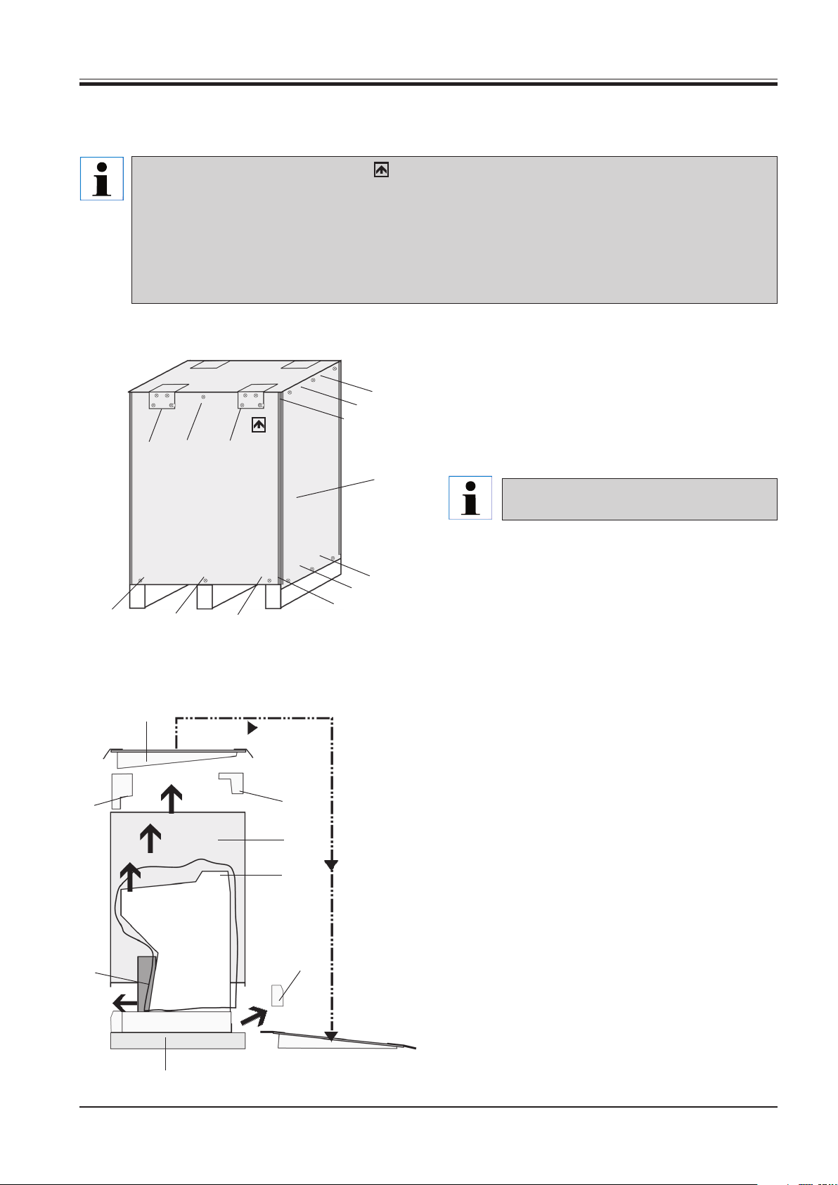
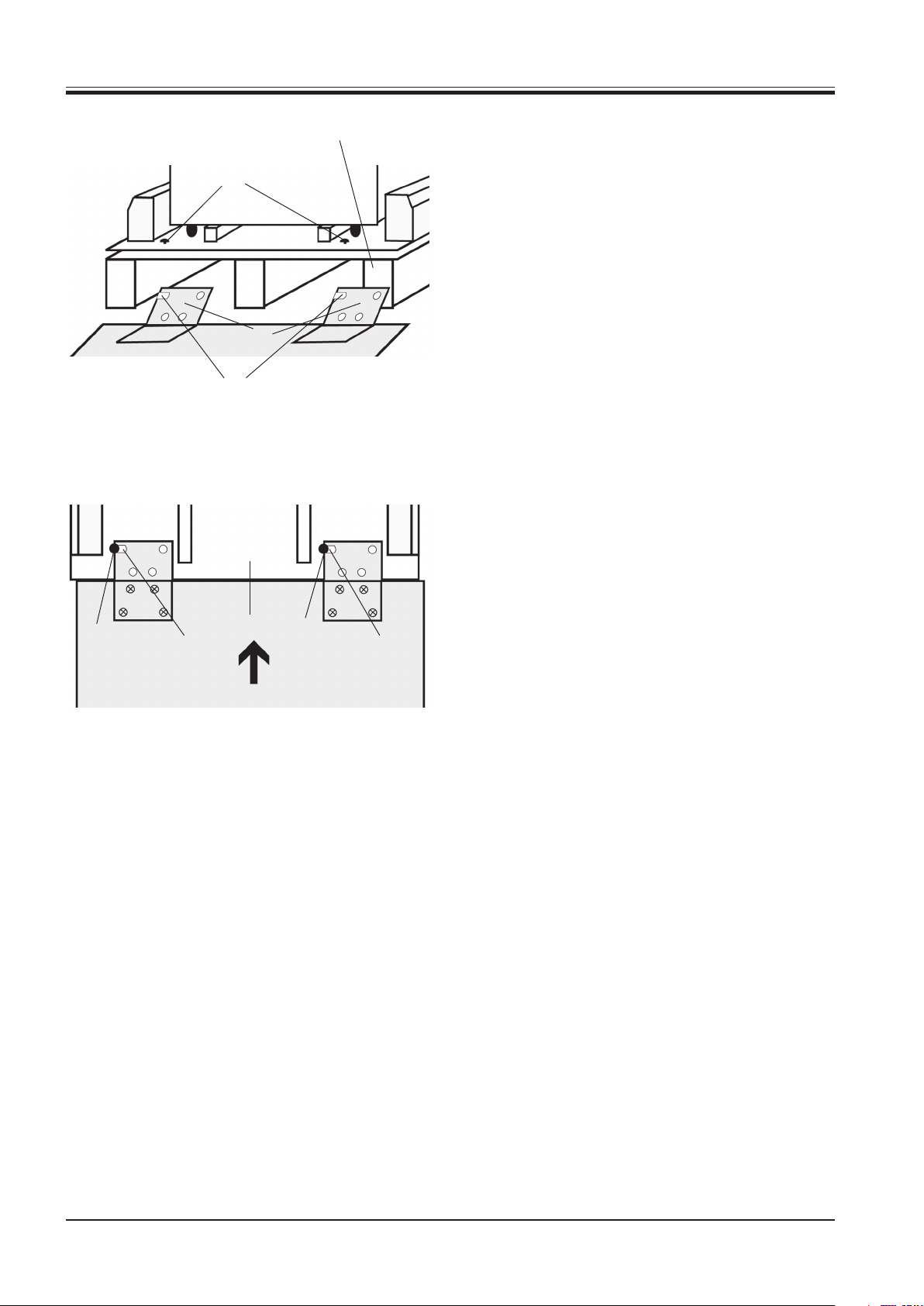
Checking if the instrument has been transported correctly
Please check the TIP (N) TELL indicators immediately after arrival of the shipment. If the TIP (N) TELL Arrow
Point is blue, this package has been on its side or tipped in transit.
Please note on the Bill of Lading and check for damage.
The same unpacking instructions are inside a transparent sheet, attached to the transport crate at arrival of the
shipment.
The following unpacking instructions shall help you in case of packing or transporting the instrument once
again.6.1
6.1 How to open the crate
6. Unpacking the instrument
1
1
1
3
2
2
7
1. Loosen 3 screws (1) at the top of the two sides of
the crate (7).
2. Loosen 4 screws of the hinges (2) at the front and
rear of the crate.
Do not loosen the screws of the hinges on the
lid of the crate!
3. Loosen 1 screw (3) at the top between the two
4
4
4
4
4
4
hinges at the front and rear of the crate.
4. Loosen 3 screws (4) at the bottom on each of the
four sides of the crate.
5
6.2 How to remove the packing materia
1. Remove the lid (5) and place on the ground beside
the transport platform (11) with the foam parts fac-
6
6
7
ing down.
2. Remove the 4 foam parts (6).
8
11
Leica CM1900 – Cryostat
9
3. Lift the body of the crate (7) straight up.
4. Take out the cardboard box (8) containing the accessories and the instruction manual at the front of
the instrument.
10
5. Remove the dust cover (9) by pulling it upward.
6. Remove the foam part (10) at the rear.
11
Page 12
6. Unpacking the instrument
11
6.3 Mounting the ramp
1. Upon removal of the foam part (10) 2 screws (12)
12
become visible on the base platform.
2. Fold down the hinges (2) at the rear and front.
3. Place the lid against the transport platform (11) from
behind.
The jogs (13) of the hinges (2) must point to the instrument.
2
13
4. Push the lid to the left sliding the jogs (13) of the
hinges under the heads of the screws (12).
12
13
11
12
13
12
Instruction manual V 5.3 – 10/2006
Page 13
6. Unpacking the instrument
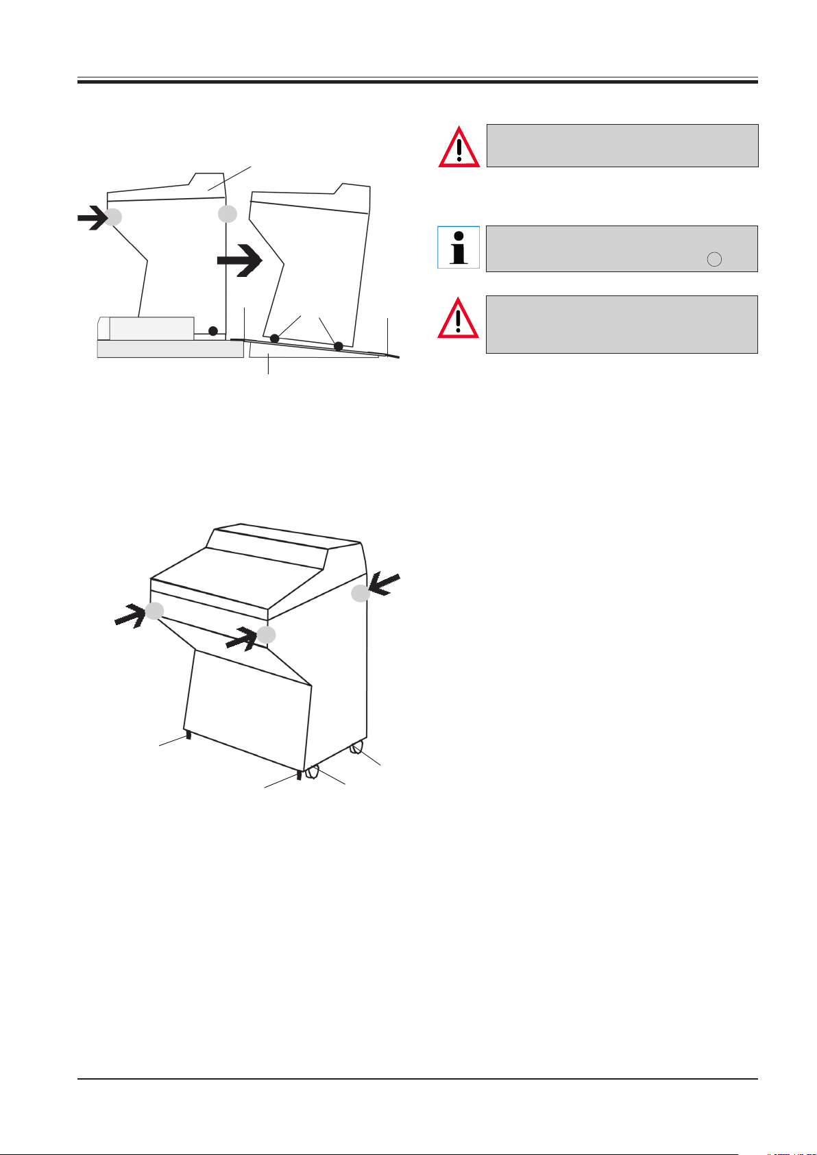
6.4 Transport to the installation site
The instrument must be transported in an up-
16
• The lid (5) forms a ramp for the instrument so it can
right position or slightly tilted (max. 30°)!
be rolled off the transport platform.
Do not grip the cabinet at the lid (16)! Grip the
cabinet only at the marked locations ( )!
Lengthwise
movement
2
14
5
2
The wheels (14) must be guided over the
hinges (2) at the front and rear. Caution: Risk
of tilting!
1. Roll the instrument backwards over the ramp off the
platform with caution.
2. Move the instrument to the installation site on its
wheels.
3. The adjustable feet (15) can support the weight of
the instrument when tipped at a slight angle (max.
30°).
Tilt
15
Leica CM1900 – Cryostat
14
15
14
13
Page 14
7. Installation
7.1 Site requirements
To ensure an adequate cooling capacity, the
instrument must be set up maintaining a minimum distance from walls and furniture (see
'Technical data')!
The place of installation must meet the following requirements:
• No direct sunlight.
• Mains power socket at a distance no greater than
appr. 3 m.
• No drafts (air condition outlets etc.).
• Even floor.
• Vibration-free floor.
• Only for indoore use.
• Obstruction-free access to the handwheel.
• Obstruction-free access to the ON/OFF switch.
• Room temperature always approx. 22 °C.
• Air humidity must not exceed 60 %.
• Distance to walls and furniture, calculated from the
cabinet:
- rear: 10 cm
- right side: 20 cm
- left side: 10 cm
• No heat dissipating appliances around.
High room temperatures and excessive air
humidity affect the cooling capacity of the cryostat and lead to the formation of condensation water in the instrument!
14
Instruction manual V 5.3 – 10/2006
Page 15
7. Installation
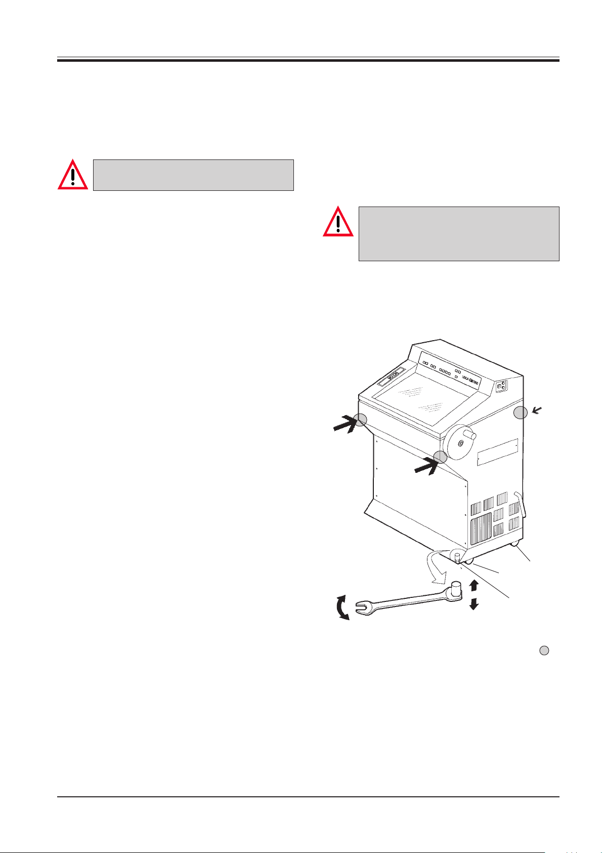
7.2 Transport to the desired site - Relocation
• First, check if the location meets the conditions
specified in 'Site requirements'.
• Transport the instrument to the desired location.
• Observe the following:
The instrument must be transported in an upright position or slightly tilted (max. 30°)!
Transport on wheels
• On even floors and for short distances the instrument can be transported on wheels. Before transportation, screw the adjustable feet (1) completely
down with the open-end wrench no. 16.
• The instrument can be rolled lengthwise and slightly
be tilted forward (see arrows). - Although the instrument cannot be rolled sideways, it can be
pushed carefully in that direction.
When tilting the instrument 2 people must
counterbalance from the frontside to prevent
the instrument from falling down and causing
severe injury!
Tilt
Lengthwise
movement
2
3
1
• When transporting the instrument on wheels (2, 3)
grip the cabinet only at the marked locations ( ).
• The adjustable feet (15) can support the weight of
the instrument when tipped at a slight angle (max.
30°).
Unscrew the adjustable feet with the open-end
wrench no. 16 (when subsequently transporting the
instrument any further on wheels, do not forget to
screw the adjustable feet down completely).
Leica CM1900 – Cryostat
15
Page 16

7. Installation
Transport with handles
• For lifting or carrying the instrument manually (e.g.
on stairs) you can use handles (4).
Screw the handles into the threads (5) of the bottom plate at both sides of the cabinet.
• The handles can be ordered from your Leica
Sales Unit.
4
4
Transport with a fork lift
• The instrument can be transported with a fork lift.
• The distance 'a' for insertion between the wheels
is max. 540 mm.
5
5
Due to the weight of the instrument (170 kg) 4
people are required for transportation (2 persons per handle).
Distance for insertion
a = max. 540 mm
To ensure a safe transportation with a fork lift
3 people are required: one operating the fork
lift, and the other 2 holding the instrument on
either side to prevent it from sliding down.
• Unscrew the adjustable feet at the installation site
(1) with the open-end wrench no. 16 (see Fig. page
16). This is absolutely necessary for a stable stand.
16
Instruction manual V 5.3 – 10/2006
Page 17

7.3 Assembly of the handwheel
1
2
3
4
• Insert the pin (1) of the handwheel shaft into the
hole (2) of the handwheel.
• Mount the spring washer (3) on the screw (4).
• Tighten the screw (4) with an Allen key no. 6.
7. Installation
• To unlock, push the locking pin (5) to the left from
the recess at the handwheel.
To dismount, proceed in reverse order.
7.4 Locking the handwheel
6
5
• For locking the handwheel rotate the handle until it
is in the upper position. Push the locking pin (5) into
the recess at the handwheel. The locking position
is marked by a black dot (6). If necessary, move the
handwheel slightly forth and back until the locking
mechanism engages.
7.5 Mounting the heat extractor
7
• Fix the holding device of the heat extractor by tightening the 2 screws (7) with the Allen key no. 4 to the
threaded holes on the left sidewall of the
cryochamber and insert the heat extractor.
Leica CM1900 – Cryostat
17
Page 18

7. Installation
7.6 Inserting the accessories
• Insert the storing shelf (1).
1
• Insert the rimmed section waste tray (2).
2
18
Instruction manual V 5.3 – 10/2006
Page 19

7.7 Inserting the optional accessories
7. Installation
• Insert the waste container (3).
3
• Insert the right storage shelf (4).
4
• Insert the section waste tray (6).• Insert the left storage shelf (5).
5
6
Leica CM1900 – Cryostat
19
Page 20

8. Operation
8.1 Precooling the knife
• To precool the knife put the open knife rest including the knife on the storage shelf inside the
cryochamber.
The knives are extremely sharp!
Handle with care!
Never try to catch a falling knife!
8.2 Installing the knife holder base
• To unlock relocate the lever to the front (1).
1
• Slide the guide (2) of the knife holder base (3) onto
the T-piece (4) of the microtome base plate as
shown.
3
2
4
• To clamp relocate the lever (1) backwards.
1
• If the lever cannot be relocated entirely for clamping, lift it up and shift it to the next position.
20
Instruction manual V 5.3 – 10/2006
Page 21

8. Operation
8.3 Inserting the knife holder
• To insert the knife holder, unlock the lever (1) turning it upward, slightly to the rear.
• Insert the knife holder (2) onto the knife holder base
(3) as shown.
1
2
• Do not connect other consumers to this electric circuit.
• Connect the mains plug to the mains power outlet
at the wall.
After transporting, wait at least 4 hours before turning the instrument on.
This waiting period is necessary to allow the
compressor oil, which may have been displaced during transport, to return to its original position.
Failure to comply with this can cause severe
damage to the instrument!
8.5 Turning on the instrument
• ON/OFF switch must be easily available.
• The automatic mains fuse is used as mains switch.
• Bring the switch of the automatic fuse (2) to the
upper position.
3
• To clamp, turn the lever (1) forward.
8.4 Connection to the mains
During the start-up of the compressor the
nominal voltage must not drop below the values specified in the 'Technical Data'.
Please note that the compressor requires a
start-up current between 30 and 40 A.
Therefore, the electric circuit at the installation site must be inspected by an electrical
engineer to ensure that it meets the requirements for a troublefree operation of the instrument.
Failure to comply with the above will cause
severe damage to the instrument!
• Check mains voltage and mains frequency to comply with the specification on the type plate.
• Turn on the mains switch (1).
• Close the sliding window.
1
To avoid frost formation always put the cover
on the quick freeze shelf.
Always cover the quick freeze shelf during
breaks and overnight.
2
Plug the instrument only to power sockets
with ground!
Leica CM1900 – Cryostat
21
Page 22

8. Operation
8.6 Leica CM1900 – Overview
Display of Actual Temperature and Set
Temperature of the specimen head display flashes during specimen head
defrost - display alternately reads "LL'' /
Actual Temperature while "Max Cool"
is activated - flasing decimal points
indicate that specimen head
refrigeration is disconnected.
Max-Cool-button to
directly
select the maximum
(lowest) temperature
of the specimen head
+/- buttons
to select specimen
head temperature
+/- buttons
toselect
cryochamber
temperature
Display of Actual Temperature and Set
Temperature of the cryochamber display flashes during chamber defrost
- flasing decimal points indicate that
chamber refrigeration is disconnected.
+/- buttons
to select
real time
+/- buttons to
select defrost
time
"Melting Snowflake"
button to activate
defrosting
Display of Real Time, Defrost Time and
Error Messages.
When display reads defrost time, the two
LEDs flash.
The LEDs are extinguished when the
control panel is locked
via the Key button.
ON/OFF button of illumination
Key button to lock/
unlock
display settings and to
turn on/off chamber or
specimen cooling
22
Instruction manual V 5.3 – 10/2006
Page 23

Luminous indication (LED) - flashes
while coarse feed is in motion and
and lights up when the specimen
head has reached its rear limit
position
Coarse Feed buttons, (Arrow
buttons) on the left of the
cryochamber.
To move the specimen head rapidly
towards the knife (lower button) or
away from the knife (upper button).
8. Operation
Luminous indication (LED) - lights
up when the specimen head has
reached its front limit position
Mounting the knife holder
onto the knife holder base
Quick freezing shelf,
with heat extractor and lowtemperature stabilizer
Leica CM1900 – Cryostat
23
Page 24

8. Operation
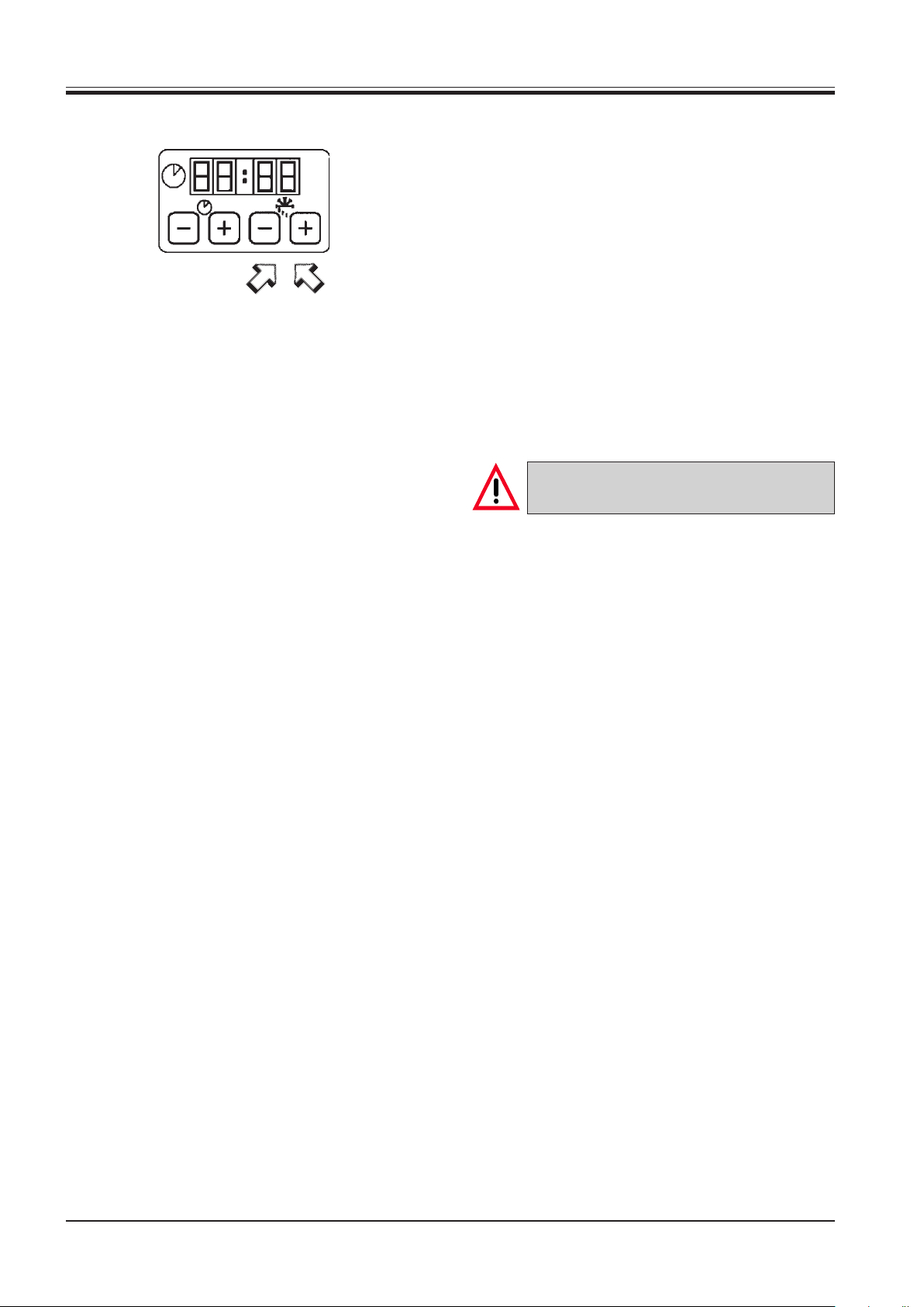
8.7 Programming the desired values
Turning the lamp on and off
• Turn the lamp on or off.
Setting the time
• Set the time.
• The actual time is set with the +/- buttons in the
control panel marked with the clock symbol.
When pushing the + or - button for more than 1 s,
the time value increases or decreases continuously (Autorepeat-function).
24
Programming the temperature of the cryochamber
• Select the desired temperature of the cryochamber.
• The temperature of the cryochamber is set and indicated on the control panel marked with the cryostat symbol.
The actual temperature is the standard indication.
For indication of the desired value, touch the + or button.
Set the desired value via the + / - buttons. When
pushing the + or - button for more than 1 s, the chamber temperature value increases or decreases
continuously.
The actual value will be indicated 5 seconds after
finishing the programming.
Instruction manual V 5.3 – 10/2006
Page 25

8. Operation
Programming the specimen temperature
• Select the desired temperature of the specimen.
• The specimen temperature is set and indicated on
the control panel marked with the specimen head
symbol.
The actual temperature is the standard indication.
For indication of the desired value, touch the + or button.
Set the desired value via the + / - buttons. When
pushing the + or - button for more than 1 s, the specimen temperature value increases or decreases
continuously.
The actual value will be indicated 5 seconds after
finishing the programming.
Specimen temperature - 'Max-Cool' function
• The snowflake button for the 'Max-Cool'-function
is in the panel with the specimen head symbol.
Push the button for programming the lowest temperature possible of the specimen head (-50 °C).
• Push the snowflake button again for stopping the
'Max-Cool'-function.
The temperature adjusts to the value programmed
prior to activating the 'Max-Cool'-function.
• Alternate flashing of 'LL' and actual temperature
indicates activation of the 'Max-Cool'-function.
Leica CM1900 – Cryostat
25
Page 26
8. Operation
Programming the defrost cycle
• Set the beginning of the automatic defrost cycle.
The automatic defrost cycle is activated once in 24
hours.
It is set with the + /- buttons on the right of the panel
with the clock symbol. The buttons are marked by a
melting snowflake.
• Touch the + or -button for indication of the beginning of the defrost cycle which has actually been
set. At the same time, the LEDs between the indication of hours and minutes are flashing.
• To change the beginning of the defrost cycle in
steps of 15 minutes push the + or -button. When
pushing the + or - button for more than 1 s, the defrost time value increases or decreases continuously.
Before starting the defrost cycle remove all
samples from the cryochamber!
• When activating the automatic defrost cycle the
specimen head temperature adjusts to a temperature between -10°C and -5°C (reduced ice formation). The specimen head cooling turns off. This is
confirmed by the flashing of the decimal points on
the panel for the specimen cooling. The specimen
cooling turns automatically back on after 4 hours,
once the chamber temperature varies by less than
5 K from the set temperature.
• If you want to turn the specimen cooling back on
manually before the automatic activation sets in,
push the + or - button on the panel for the specimen cooling and then the key button.
• The temperature of the specimen cooling first raises
to +10°C and then adjusts to the programmed specimen temperature.
26
Instruction manual V 5.3 – 10/2006
Page 27

8. Operation
Before defrosting the cryochamber remove all
samples!
Manual defrosting of the cryochamber
• Push the manual defrost button (with the melting
snowflake) on the left over the key button to activate the defrost cycle of the cryochamber on demand.
• Activation is confirmed by an audible signal.
• Then, push + or - button on the panel for the
cryochamber temperature.
• The manual defrost cycle (9 min.) is activated.
• There is a flashing indication of the temperature of
the cryochamber during the whole defrost cycle.
• If necessary, push the manual defrost button on the
panel for the cryochamber temperature.
• When activating the manual defrost cycle the speci-
men head temperature adjusts to a temperature between -10°C and -5°C (reduced ice formation). The
specimen head cooling turns off. This is confirmed
by the flashing of the decimal points on the panel
for the specimen cooling.
• Ten seconds after the manual defrost cycle has
been completed, the specimen cooling turns back
on.
Leica CM1900 – Cryostat
27
Page 28

8. Operation
Before defrosting the specimen head remove
all samples!
Manual defrosting of the specimen cooling
• Push the manual defrost button (with the melting
snowflake) on the left over the key button to activate the defrost cycle of the specimen head.
• Activation is confirmed by an audible signal.
• Then, push + or - button on the panel for the specimen temperature.
• There is a flashing indication of the specimen temperature during the whole defrost cycle.
• For 10 minutes the specimen head is adjusted to a
temperature of 20°C and 30°C.
• Subsequently, the instrument adjusts to the specimen temperature which has been programmed
prior to the manual defrost cycle.
• If necessary, push the manual defrost button again
to deactivate the manual defrost cycle.
Display lock
• Push the key button for 5 seconds to protect the
programmed values against unintended alterations.
The programmed values cannot be modified after
having pushed the key button.
• Push the key button once more for 5 seconds to
unlock the display.
• When the display is locked, the LEDs between the
hour and minute indication on the time panel are
turned off.
• Key button is also used for turning on/off the chamber and specimen cooling:
For this purpose, push the + or - button of the corresponding panel and subsequently press the key
button.
28
Instruction manual V 5.3 – 10/2006
Page 29

8. Operation
Error messages
- The display indicates the following malfunctions.
Error code E 001:
Temperature limit error or breaking of the temperature sensor of the specimen cooling system.
Error code E 011:
Temperature limit error or breaking of the temperature sensor of the cryochamber cooling system.
- If the instrument is being exposed to temperatures
of more than +35 °C over a long period, e. g. during
transportation a temperature limit error may be indicated.
This error message disappears as soon as the instrument has reached a temperature lower than 35
°C.
If the error message does not disappear, call the
technical service.
Never leave samples in the cryochamber! The instrument is not made for storing frozen
specimen!
Unfixed samples used in cryostats must always be considered as possibly contaminated! Ensure that the appropriate disinfection methods are applied (see 'Cleaning and
Disinfection')!
Leica CM1900 – Cryostat
29
Page 30
9. Daily operation
9.1 Selection of the adecuate chamber temperature
• For choosing the adecuate chamber temperature,
see the temperature chart on page 50.
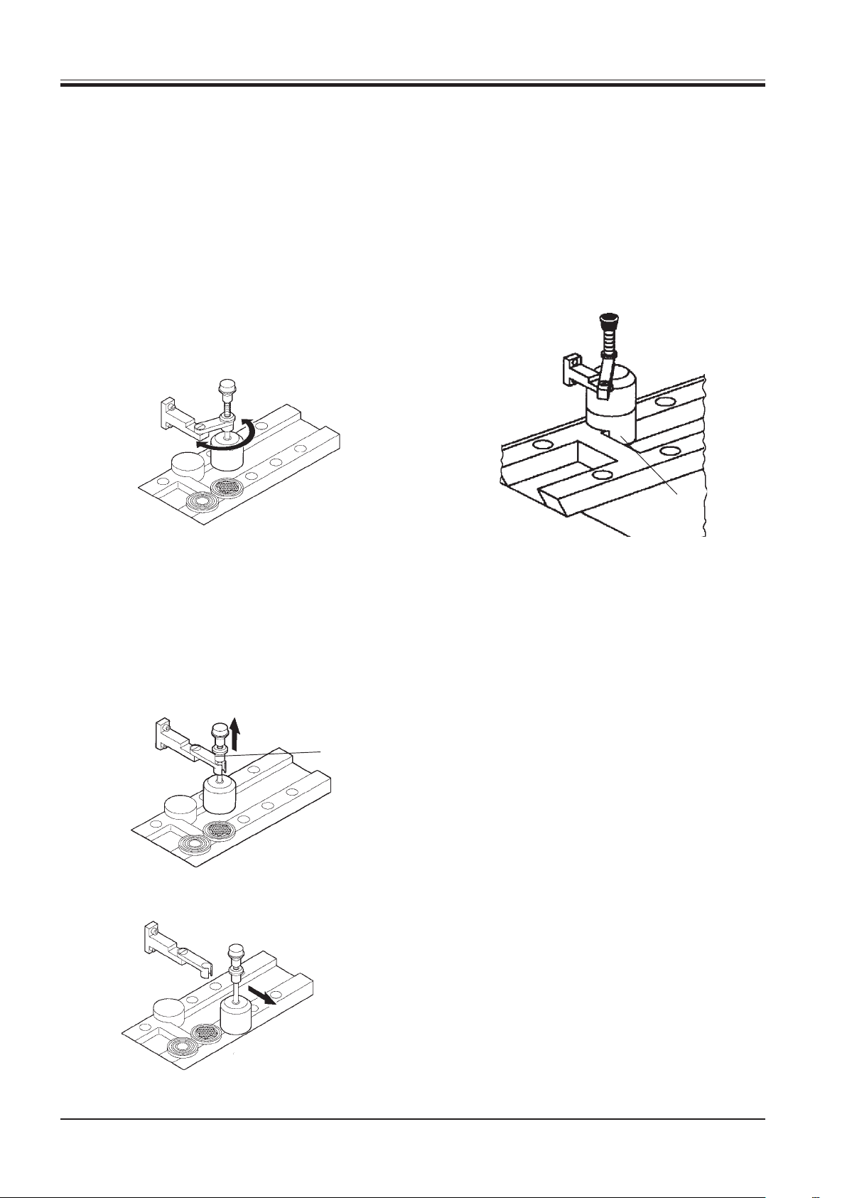
9.2 Specimen freezing
• Freeze the specimen on the quick freeze shelf onto
the specimen disc.
• Place the heat extractor onto the specimen to speed
up the freezing process.
• After freezing the specimen insert the heat extractor back in the fixing device and place it in its original position on the low-temperature stabilizer (2).
• The low-temperature stabilizer cools down the heat
extractor to the lowest temperature possible, thus
ensuring maximum performance when freezing
specimen.
2
• Rotate the heat extractor to place it on the three
freezing stations within reach.
To place the heat extractor onto one of the other
freezing stations, lift the ring (1), remove the heat
extractor from the fixing device and put it on the
desired station.
1
30
Instruction manual V 5.3 – 10/2006
Page 31

9. Daily operation
9.3 Activating / deactivating the specimen
cooling
• The specimen cooling is activated by subsequently
pushing the + or - button in the control panel for
specimen cooling and the key button.
• Deactivation of the specimen cooling is done in the
same way.
To activate / deactivate the specimen or
cryochamber cooling you must push the relevant buttons subsecuently. Do not push simultaneously!
9.4 Activating / deactivating the
cryochamber cooling
• The chamber cooling is activated by subsequently
pushing the + or - button in the control panel for
• Deactivation of the chamber cooling is done in the
same way.
9.5 Inserting the specimen discs in the specimen head
Prior to manipulating the knife and specimen,
or changing the specimen or knife, always
lock the handwheel and cover the cutting
edge with the knife guard!
• First, lock the handwheel.
Bring the handle to the upper position. The locking
pin must meet the black mark on the cabinet.
• Push the locking pin into the recess at the
handwheel.
• To control if the locking mechanism has engaged
try to move the handwheel slightly back and forth.
• Insert the specimen disc in the specimen head.
• Loosen the screw (1) on the specimen head turning
it counterclockwise, insert the specimen disc and
retighten the screw.
1
Leica CM1900 – Cryostat
31
Page 32

9. Daily operation
9.6 Inserting the knife in the knife holder
• Insert and clamp the precooled knife/blade in the
knife holder.
For further details please refer to the separate instruction manual for your knife holder.
Take care when handling microtome knives
and disposable blades. The cutting edge is
extremely sharp an can cause severe injury!
Never leave knives and knife holders with a
knife/blade mounted lying around!
Do not place a knife on a table with the cutting edge facing upward!
Never try to catch a falling knife!
Prior to manipulating the knife and specimen,
or changing the specimen or knife, always
lock the handwheel and cover the cutting
edge with the knife guard!
Always lock the handwheel and cover the
cutting edge of the knife with the knife guard
during breaks!
Avoid contact with cold parts of the instrument as this can cause frostbite!
32
Instruction manual V 5.3 – 10/2006
Page 33

9. Daily operation
9.7 Moving the specimen towards or away
from the knife via coarse feed
• Push the coarse feed buttons, situated on the left
upper side of the cabinet, to move the specimen
towards or away from the knife.
The upper coarse feed button automatically retracts the specimen from the knife, the lower button moves the specimen toward the knife.
9.8 Trimming
• When the specimen has been moved towards the
knife it can be trimmed to the required sectioning
plane.
The section thickness can be adjusted by turning
the knob on the right beside the specimen cylinder.
• Start sectioning after having finished trimming or
having reached the appropriate section thickness.
• Only touch the upper coarse feed button slightly to
retract the specimen from the knife. The specimen
cylinder automatically moves to the rear limit.
The return movement can be stopped by pressing
one of the coarse feed buttons.
• The forward movement only operates as long as the
button is pressed. (This is a safety feature to protect both specimen and knife from damage!)
Always observe the specimen during the forward movement, thus avoiding that specimen
and knife collide by mistake!
A collision can cause severe damage both to
the knife and to the specimen and the specimen disc!
Leica CM1900 – Cryostat
33
Page 34

9. Daily operation
9.9 Adjustment of the anti-roll guide
• Adjust the anti-roll guide to the knife holder before
sectioning.
• Adjust the anti-roll guide correctly.
For further details of adjusting the anti-roll guide
please refer to the instruction manual for knife holders.
Attention: The glass anti-roll plate of the knife
holder CE; CN and CE-TC can be cleaned either
with acetone or alcohol.
9.10 Sectioning
• When sectioning, make sure that the section
smoothly slides down between the anti-roll plate
and the knife or the pressure plate of the knife
holder.
• There are two different methods of taking sections:
• 1. Applying the section onto a warm slide:
Fold back the anti-roll plate and carefully approach
a slide of room temperature to the section.
The section 'flies' onto the slide and adheres tightly
to the slide's surface.
Unfortunately, it is not possible to orientate the section subsequently on the slide.
• 2. Applying the section onto a precooled slide:
Place the section with a smooth brush on a slide
which has been cooled down to the temperature of
the cryochamber.
Unfortunately, the section does not lay smoothly on
the slide and must be smoothed with a brush.
When using a precooled slide, always warm it with
your hand from the bottom side after the specimen
has been placed smoothly on it, thus making sure
that the section adheres tightly to it and does not
slide down when going on with preparation (e. g.
staining).
Take care when sectioning. The cutting edge
of the knife is not covered!
34
Instruction manual V 5.3 – 10/2006
Page 35

10. Cleaning and disinfection
10.1 Cleaning and disinfection
The microtome is encapsulated splash-proof
in the cryochamber. Thus, spray disinfection
with Leica Cryofect is possible.
When disinfecting, please take appropriate
protective measures (gloves, mask, protective
clothing, etc.).
When using detergents and disinfectants
please comply with the safety precautions of
the disinfectant manufacturer.
Only use acetone for cleaning the plastic antiroll plate of the knife holder CN. The glass
anti-roll plate of the knife holder CE can be
cleaned either with acetone or alcohol.
Do not use uncontrolled external heaters for
drying the cryochamber. This can cause damage to the cooling system!
• Turn off the instrument and wait until the
cryochamber has room temperature.
• The microtome is encapsulated splash-proof in the
cryochamber. Thus, it is not necessary to remove
it for disinfection.
• Spray disinfection is possible.
• Before disinfecting, put an appropriate vessel un-
derneath the marked hose connection on the righthand side of the cabinet (see below).
• Drain the cleaning liquid through the hose after the
prescribed reaction time by pulling the stopper.
• Dispose of the waste liquid according to the waste
disposal regulations.
10.2 Turning the instrument back on
Do not turn the instrument on before the
cryochamber is completely dry!
Frost formation!
The front panel and the slit cover of the microtome must be completely dry before turning on the instrument!
Dry all parts completely before reinserting
them in the cryochamber!
• The stopper must be plugged to the hose again!
Leica CM1900 – Cryostat
35
Page 36

11. Removal of the microtome
11.1 How to remove the microtome:
It is not necessary to remove the microtome
for disinfecting the cryochamber.
Prior to removing the microtome, turn the instrument off with the mains switch and pull
the mains plug!
Remove the sliding window before removing
the microtome (see at page 41)!
Before removing the microtome, lock the
handwheel in the lowest position. When removing the microtome, the specimen head
will rapidly fall down and might injure the
operator's hands!
1. Remove the section waste tray .
2. Loosen the specimen head turning the Allen key no.
5. counterclockwise.
3. Pull out the specimen head carefully and place it on
the storage shelf which is on the left of the microtome.
36
Instruction manual V 5.3 – 10/2006
Page 37

11. Removal of the microtome
4. Hold the front panel of the microtome as shown
(seizing the border with your left hand and the opening with your right hand) and take it out.
5. Take out the semicircular slit cover.
6. Loosen the central screw with the Allen key no. 5.
7. Pull the microtome forward until the cable becomes
reachable.
Disconnect the cable and pull the microtome out of
the guidance and remove it from the cryochamber.
Keep in mind that the microtome is heavy!
Leica CM1900 – Cryostat
37
Page 38

12. Reinstallation of the microtome
12.1 How to return the microtome to the cryochamber
The microtome must be entirely dry before reinstallation. Humidity inside will condense
and freeze, causing malfunctions and damage!
Dry all parts completely before reinserting
them in the cryochamber!
The cooling chamber must be entirely dry
when turning on the instrument (Frost formation)!
When removing the microtome for cleaning
or disinfection, please keep in mind the safety
instructions in chapter 10 'Cleaning and Disinfection'.
2. While pressing the microtome against the left guidance tighten the central screw with the Allen key
no. 5.
1. Insert the microtome in the cryochamber.
Connect the cable before pushing the microtome
completely back.
3. Mount the semicircular slit cover from behind on
the front panel of the microtome.
38
Instruction manual V 5.3 – 10/2006
Page 39

12. Reinstallation of the microtome
4. Mount both parts together on the specimen cylinder of the microtome.
5. Mount the specimen head on the specimen cylinder.
6. Tighten the specimen head with the Allen key no. 5
by turning it clockwise.
7. Insert the section waste tray.
Leica CM1900 – Cryostat
39
Page 40

13. Maintenance
13.1 General maintenance
5
1
3
2
The microtome is virtually maintenance-free. To ensure
a smooth operation of the instrument over several years
we recommend the following:
• Have the instrument inspected by a qualified service engineer authorized by us once a year.
• Enter into a service contract at the end of the warranty period. For further information, please contact your local Leica service center.
• Clean the instrument daily.
4
• From time to time:
lubricate the seat of the heat extractor (1), the
clamping piece (T piece) (2) and the clamping lever
(3) on the microtome base plate as well as the specimen cylinder (4) slightly with cryostat oil. Press the
coarse feed button (5) to move the specimen cylinder forward, apply some drops of oil on the cylinder and move it back to the final home position.
• Clean the ventilation slits of the liquefiers on both
sides of the instrument with a brush, broom or
vacuum cleaner to free from dust and dirt in the direction of the fins.
• Do not carry out any repairs on your own as this
will invalidate the warranty.
Repairs may only be carried out by qualified service engineers authorized by Leica.
40
Instruction manual V 5.3 – 10/2006
Page 41

13. Maintenance
13.2 Replacement of the lamp
1
2
Turn the instrument off with the mains switch
and pull the mains plug before replacing the
lamp!
• Slightly lift the sliding window (1) holding it by the
grip (2) and pull it out to the front.
If the lamp is broken, it must be replaced by
the technical service, as the replacement involves a high risk of injury!
Removal of the lamp
• The lamp is mounted behind a glare shield and
therefore not visible.
• Touch the lamp for better orientation.
• Lightly tilt the flourescent tube down to the left and
pull it out of the clip (3).
• Hold the lamp with both hands and pull it to the left
out of the holder (4).
Only use lamps of the same specification!
Installation of the new lamp
3
4
Type:
(230 V / 50 Hz) OSRAM DULUX S - 11 W
(120 V / 60 Hz) OSRAM DULUX S - 13 W
• Hold the lamp in the correct mounting position as
shown and push it to the right until it engages in the
holder.
• Replace the sliding window.
• Reconnect the instrument to the mains power and
turn it on.
Leica CM1900 – Cryostat
41
Page 42

14. Troubleshooting
Problem Causes Remedies
Frost on chamber walls and microtome
Sections smear
Sections splinter
Sections not properly flattened
Sections not properly flattened despite
correct temperature and correctly
aligned anti-roll plate
Cryostat is exposed to air currents
(open windows and doors, air
conditioning).
Frost built-up by breathing into the
cryochamber.
Specimen not cold enough.
Anti-roll plate not yet cold enough,
thus warming the section.
Specimen too cold.
Static electricity/air currents.
Specimen not cold enough.
Large area specimen.
Anti-roll plate poorly positioned.
Anti-roll plate poorly aligned with knife
edge.
Incorrect clearance angle.
Blunt knife.
Dirt on knife and/or anti-roll plate.
Top edge of anti-roll plate damaged.
Blunt knife.
Change place of installation for the
cryostat.
Wear mouth protection.
Select lower temperature.
Wait until knife and/or anti-roll plate
have reached chamber temperature.
Select higher temperature.
Remove cause.
Select lower temperature.
Trim the specimen parallel, increase
section thickness
Reposition anti-roll plate.
Align correctly.
Set correct angle.
Use different part of the knife or
replace the knife.
Clean with dry cloth or brush.
Replace anti-roll plate.
Use different part of the knife or
replace the knife.
Sections curl on anti-roll plate
Scraping noise during sectoning and
specimen return movement
Ridged sections
Chatter during sectioning
Condensation on anti-roll plate and
knife during cleaning
Anti-roll plate does not protrude far
enough beyond the knife edge.
Anti-roll plate protrudes too far beyond
the knife edge and is scraping against
the specimen.
Knife damaged.
Edge of anti-roll plate damaged.
Specimen insufficiently frozen onto the
specimen disc.
Specimen disc not clamped tightly.
Knife not clamped tightly enough.
Specimen has been sectioned too
thickly and has detached from disc.
Very hard, inhomogeneous specimen.
Blunt knife.
Knife profile inappropriate for
specimen cut.
Incorrect clearance angle.
Brush, forceps and/or cloth too warm.
Readjust correctly.
Readjust correctly.
Use different part of the knife or
replace the knife.
Replace anti-roll plate.
Refreeze specimen onto the disc.
Check disc clamping.
Check knife clamping.
Refreeze specimen onto the disc.
Increase section thickness; reduce
specimen surface area if necessary.
Use different part of the knife or
replace knife.
Use knife with differnt profile.
Set correct angle.
Store all tools on storage shelf in the
cryochamber.
42
Instruction manual V 5.2 – 10/2002
Page 43

Problem Causes Remedies
14. Troubleshooting
Anti-roll plate damaged after
adjustment
Thick-thin sections
Tissue sticks or crumbles on the antiroll plate
Anti-roll plate too high above the knife
edge. The adjustment was carried out
in the direction of the knife.
Temperature incorrect for the tissue
cut.
Knife profile inappropriate for the
specimen cut.
Ice buildup in the knife back.
Handwheel speed not uniform.
Knife not clamped tightly enough.
Specimen disc not clamped tightly
enough.
Cryocompound applied to cold
specimen disc; specimen detached
from disc after freezing.
Blunt knife.
Inappropriate section thickness.
Incorrect clearance angle.
Microtome not properly dry before
reinstallation.
Dried specimen.
Anti-roll plate is too warm or
incorrectly positioned.
Fat on the corner or edge of anti-roll
plate.
Anti-roll plate not correctly fixed.
Rust on the knife.
Replace anti-roll plate.
Be more careful next time!
Select correct temperature.
Use knife with different profile (c or d).
Remove ice.
Adapt speed.
Check knife clamping.
Check disc clamping.
Apply cryocompound to warm disc,
mount specimen and freeze.
Use different part od the knife edge or
replace knife.
Select correct section thickness.
Set correct angle.
Dry microtome thoroughly.
Prepare new specimen.
Cool down anti-roll plate, or reposition
correctly.
Remove fat from anti-roll plate.
Fix correctly.
Remove rust.
Flattened sections curl up when antiroll late is picked up
Sections tear
Inconsistent or insufficient specimen
feed
Anti-roll plate too warm.
Temperature too low for the tissue cut.
Blunt part, dirt, dust, frost or rust on
the knife.
Top edge of the anti-roll plate
damaged.
Hard particles in the tissue.
Dirt on knife back.
Microtome was not entirely dry when
switching refrigeration, which
produced ice built up in the
micrometer feed system.
Microtome defective.
Cool down anti-roll plate.
Increase temperature and wait.
Remove cause.
Replace anti-roll plate.
- - Clean.
Remove microtome and dry
thoroughly.
Call technical service.
Leica CM1900 – Cryostat
43
Page 44

14. Troubleshooting
Problem Causes Remedies
Cryostat inoperational
Specimen disc cannot be removed
No or insufficient refrigeration of the
cryochamber
Sliding window collects
condensation
No or insufficient refrigeration of the
specimen cooling system
Lamp does not work
Mains plug not properly connected.
Defective fuses, or automatic fuse has
triggered.
Moisture on the underside cause the
specimen to freeze to the freezing
shelf or specimen head.
Stopper not placed in drain hole.
Cooling system or electronic drive
defective.
Air humidity and room temperature too
high.
Cooling system or electronic drive
defective.
Lamp defective.
Switch defective.
Check if properly connected.
Replace fuses, or switch automatic
fuse back on. If not possible, call
technical service.
Apply concentrated alcohol to the
contact point.
Replace the stopper.
Call technical service.
Comply with the requirements for the
installation site.
Call technical service.
Check lamp and replace it, if
necessary.
Call technical service.
44
Instruction manual V 5.2 – 10/2002
Page 45

15. Temperature Selection Chart
Tissue -10°C – - 15 °C -15°C – -25 °C -25 °C – -50 °C
Adrenals
Bone marrow
Brain
Bladder
Breast- fatty
Breast - little fat
Cartilage
Cervix
Fat
Heart and vessel
Intestine
Kidney
Laryngeal
Lip
Liver
Lung
Lymphoid
Musclular
Nose
Pancreas
Prostate
Ovary
Rectal
Skin with fat
Skin without fat
Spleen or bloody tissue
Testicular
Thyroid
Tongue
Uterus curettings
❉❉
❉
❉
❉
❉
❉
❉❉
❉
❉
❉
❉
❉
❉
❉❉
❉
❉
❉
❉
❉
❉
❉
❉
❉
❉
❉
❉❉
❉❉
❉
❉
❉
- The temperature values given above are based on long-term experience, however, these are only ap
proximate values, as any tissue may require particular adjustments.
Leica CM1900 – Cryostat
45
Page 46

16. Optional accessories
16.1 Orienting specimen head
Mounting the orienting specimen head:
1. Loosen the specimen head (1) turning the Allen key
no. 5 counterclockwise.
2. Pull out the specimen head (1) carefully and place
it on the base.
3. Loosen 4 screws on the insulating ring (2) with an
Allen key no. 3. Remove insulating ring and adapter
(3).
1
2
3
4. Mount insulating ring (2) on the short adapter (3a)
of the specimen orientation and fix both parts with
the 4 short screws to the corresponding threaded
bores on the cylinder.
5. Mount the specimen head (1) on the insulating ring
(2) and fix it with the Allen key no. 5.
6. Insert the specimen orientation (4) in the specimen
head (1) and fix the clamping screw (5).
7. Insert the specimen disc (6) and fix the clamping
screw (7).
8. The specimen can be oriented when the clamping
lever (8) is loose. Tighten lever (8) after orienting
the specimen.
2
6
7
8
3a
4
5
46
1
Instruction manual V 5.3 – 10/2006
Page 47

16.2 Thermal block
• The thermal block (1) facilitates the removal of the
frozen specimen from the specimen disc.
• Place the cap (2) on the required side, so that the
appropriate location hole for the specimen disc is
visible.
• Insert the shaft of the specimen disc in the appro-
priate location hole (3) at the top or bottom of the
thermal block.
• After about 20 seconds, the frozen specimen can
be removed from the specimen disc with forceps.
• If the cap is too loose, readjust it with the small
screw (4). Do not overtighten the screw!
• Once the specimen is removed, take the thermal
block out of the cold cryochamber.
16. Optional accessories
3
1
2
4
Keep the thermal block outside the
cryochamber at room temperature. Place it in
the cryochamber only for specimen removal.
Leica CM1900 – Cryostat
47
Page 48

17. Ordering information
Knife holder base ...........................................................................................................................................0419 26140
Knife holder CN ..............................................................................................................................................0419 33993
Knife support................................................................................................................................................... 0419 19426
Knife support................................................................................................................................................... 0419 19427
Anti-roll plate, assy. 50mm............................................................................................................................ 0419 33981
Anti-roll plate, glass .......................................................................................................................................0419 33816
Knife holder CE low prof................................................................................................................................ 0419 33990
Knife holder CE high prof. ............................................................................................................................. 0419 33991
Knife holder CE ............................................................................................................................................... 0419 33992
Pressure plate rear HP, 22° ..........................................................................................................................0502 29553
Pressure plate rear LP, 22°........................................................................................................................... 0502 29551
Anti-roll plate, assy. 70mm............................................................................................................................ 0419 33980
Anti-roll plate, assy. 70mm............................................................................................................................ 0419 37258
Anti-roll plate, assy. 70mm............................................................................................................................ 0419 37260
Anti-roll plate, glass .......................................................................................................................................0419 33813
Anti-roll guide, assy. ......................................................................................................................................0419 35693
Knife holder CE-TC .........................................................................................................................................0419 32073
Specimen disc 20 mm diam. .........................................................................................................................0370 08636
Specimen disc 25 mm diam. .........................................................................................................................0416 19275
Specimen disc, 30mm diam. .........................................................................................................................0370 08587
Specimen disc, 40mm .................................................................................................................................... 0370 08637
Specimen disc ................................................................................................................................................0419 26491
Specimen stage .............................................................................................................................................. 0419 26750
Transfer block................................................................................................................................................. 0416 38207
Heat extractor ................................................................................................................................................. 0452 27918
Heat extractor ................................................................................................................................................. 0443 26836
Thermal block .................................................................................................................................................0398 18542
90° prism ..........................................................................................................................................................0443 25949
Specimen head............................................................................................................................................... 0452 28800
Miles adapter .................................................................................................................................................. 0436 26747
Anti-static kit low-prof................................................................................................................................... 0800 37739
Anti-static kit high-pr. ....................................................................................................................................0800 37740
Cryoembed.system cpl.set ........................................................................................................................... 0201 39115
Embed. well bar set 18 mm ...........................................................................................................................0201 39116
Embed. well bar set 24 mm ...........................................................................................................................0201 39117
Embed. well bar set 30 mm ...........................................................................................................................0201 39118
Freez.griddle/block elev. ...............................................................................................................................0201 39119
Embedding well bar 4x18mm ........................................................................................................................0201 39120
Embedding well bar 4x24mm ........................................................................................................................0201 39121
Embedding well bar 3x30mm ........................................................................................................................0201 39122
Spec. stage square 28 mm ........................................................................................................................... 0201 39122
Spec. stage square 36 mm ........................................................................................................................... 0201 39124
Ovewr-disc heat extractor ...........................................................................................................................0201 39125
Bin for discs ..................................................................................................................
Dispensing slides 8 pcs. ................................................................................................................................ 0201 39127
Storage kit ....................................................................................................................................................... 0452 28763
Case w/embedding systems.........................................................................................................................0201 40670
..................................0201 39126
48
Instruction manual V 5.3 – 10/2006
Page 49

17. Ordering information
Easy Dip staining cnt. wt ...............................................................................................................................0712 40150
Easy Dip staining cnt. pk ...............................................................................................................................0712 40151
Easy Dip staining cnt.grn .............................................................................................................................. 0712 40152
Easy Dip staining cnt. yl ................................................................................................................................ 0712 40153
Easy Dip staining cnt. bl ................................................................................................................................0712 40154
Easy Dip Stain. rack grey ..............................................................................................................................0712 40161
Safety gloves size M ...................................................................................................................................... 0340 29011
OCT-Compound 125 ml .................................................................................................................................. 0201 08926
Cryostat oil, type 407 ...................................................................................................................................... 0336 06100
Leica Cryofect 4 x 250 ml...............................................................................................................................0387 36193
Leica CM1900 – Cryostat
49
Page 50

18. Warranty and service
Warranty
Leica Microsystems Nussloch GmbH guarantees that the contractual product delivered
has been subjected to a comprehensive quality control procedure based on the Leica
in-house testing standards, and that the product is faultless and complies with all technical specifications and/or agreed characteristics warranted.
The scope of the warranty is based on the content of the concluded agreement. The
warranty terms of your Leica sales organization or the organization from which you
have purchased the contractual product shall apply exclusively.
Technical service information
If you require technical service or replacement parts, please contact your Leica sales
representative or dealer who sold the product.
Please provide the following information:
• Model name and serial number of the instrument.
• Location of the instrument and name of the person to contact.
• Reason for the service call.
• Date of delivery.
Decommissioning and disposal
The instrument or parts of the instrument must be disposed of in compliance with the
local laws.
50
Instruction manual V 5.3 – 10/2006
 Loading...