

Page 1
Instruction Manual
Leica CM1850 V2.2 English – 12/2003
Always keep this manual near the instrument!
Read carefully prior to operating the instrument!
Leica CM1850
Cryostat
Page 2

Page 3
INFORMATION
The information, numerical data, notes and value
judgments contained in this manual represent the
current state of scientific knowledge and stateof-the-art technology as we understand it following thorough investigation in this field. We are
under no obligation to update the present manual
periodically and on an ongoing basis according
to the latest technical developments, nor to provide our customers with additional copies, updates etc. of this manual.
For erroneous statements, drawings, technical illustrations etc. contained in this manual
we exclude liability as far as permissible according to the national legal system applicable
in each individual case. In particular, no liability whatsoever is accepted for any financial loss
or consequential damage caused by or related
to compliance with statements or other information in this manual.
Statements, drawings, illustrations and other
information as regards contents or technical
details of the present manual are not to be considered as warranted characteristics of our
products.
These are determined only by the contract provisions agreed between ourselves and our
customers. Leica reserves the right to change
technical specifications as well as manufacturing processes without prior notice. Only in
this way is it possible to continuously improve
the technology and manufacturing techniques
used in our products.
This document is protected under copyright laws.
Any copyrights of this document are retained by
Leica Microsystems Nussloch GmbH.
Any reproduction of text and illustrations (or of
any parts thereof) by means of print, photocopy,
microfiche, web cam or other methods – including any electronic systems and media – requires
express prior permission in writing by Leica
Microsystems Nussloch GmbH.
For the instrument serial number and year of
manufacture, please refer to the name plate at
the back of the instrument.
© Leica Microsystems Nussloch GmbH
Leica Microsystems Nussloch GmbH
Heidelberger Str. 17 - 19
D-69226 Nussloch
Germany
Phone: +49 (6224) 143-0
Fax: +49 (6224) 143-200
eMail: histo_info@leica-microsystems.com
Internet: http://www.histo-solutions.com
Leica CM1850 – Cryostat
3
Page 4

Table of contents
1. Important Information ................................................................................................................ 6
1.1 Symbols used in this manual and their meaning ...................................................................................... 6
1.2 Qualification of personnel ............................................................................................................................. 6
1.3 Designated use ................................................................................................................................................ 6
1.4 Instrument type: ............................................................................................................................................6
2. Safety ............................................................................................................................................ 7
2.1 Safety features..............................................................................................................................................7
2.1.1 Locking the handwheel............................................................................................................................... 7
2.1.2 Knife guard .....................................................................................................................................................8
2.2 General information on instrument design and safe handling ..............................................................8
2.3 Operating conditions ...................................................................................................................................9
2.5 Cleaning and disinfection.........................................................................................................................10
2.6 Removal of the microtome ........................................................................................................................10
2.7 Maintenance ............................................................................................................................................... 11
3. Technical data .......................................................................................................................... 12
4. Unpacking and installation ....................................................................................................14
4.1 Site requirements........................................................................................................................................14
4.2 Transport to the desired location ...........................................................................................................14
4.3 Standard delivery........................................................................................................................................ 15
4.4 Handwheel assembly .................................................................................................................................16
5. Setup ........................................................................................................................................... 17
5.1 Connection to mains power ..................................................................................................................... 17
5.2 Prior to operation ........................................................................................................................................ 17
5.3 Leica CM1850 - Overview ..........................................................................................................................18
5.4 Mains switch and automatic mains fuse ..............................................................................................20
5.5 Turning the instrument on ........................................................................................................................ 20
6. Control panel operation........................................................................................................... 21
6.1 Control panel 1 ............................................................................................................................................ 21
6.2 Programming the desired values.............................................................................................................21
6.2.1 Setting the time ...........................................................................................................................................21
6.2.2 Setting the automatic defrost time (cryochamber) ............................................................................ 22
6.2.3 Selecting the cryochamber temperature ..............................................................................................22
6.2.4 Activation of the Peltier element (option).............................................................................................23
6.2.5 Manual defrosting of the quick freeze shelf ........................................................................................23
6.2.6 Manual defrosting of the cryochamber ................................................................................................ 24
6.3 Display lock ..................................................................................................................................................24
6.4 Control panel 2 - Electric coarse feed ................................................................................................... 25
4
Instruction Manual V 2.2 – 12/2003
Page 5

Table of contents
7. Daily use of the instrument..................................................................................................... 26
7.1 Specimen freezing ......................................................................................................................................26
7.1.1 Quick freeze shelf....................................................................................................................................... 26
7.1.2 Stationary heat extractor (accessory)* ................................................................................................ 26
7.2 Specimen discs ........................................................................................................................................... 27
7.2.1 Inserting the specimen discs in the specimen head .........................................................................27
7.2.2 Specimen orientation ................................................................................................................................27
7.3 Sectioning ....................................................................................................................................................28
7.3.1 Trimming the specimen .............................................................................................................................28
7.3.2 Section thickness setting ......................................................................................................................... 28
7.4 Temperaturew selection chart (in minus °C) ....................................................................................... 29
7.5 Defrosting ..................................................................................................................................................... 30
7.5.1 Automatic defrosting of the cryochamber............................................................................................30
7.5.2 Manual defrosting of the cryochamber ................................................................................................ 30
7.5.3 Manual defrosting of the quick freeze shelf ........................................................................................31
7.6 Terminating work ........................................................................................................................................ 31
7.6.1 Terminating daily work ..............................................................................................................................31
7.6.2 Shutdown for a longer period .................................................................................................................. 32
8. Troubleshooting ........................................................................................................................ 33
8.1 Error messages in the display ..................................................................................................................33
8.2 Temperature control button .....................................................................................................................33
8.3 Possible causes and remedies................................................................................................................34
9. Cleaning, disinfection, maintenance.................................................................................... 39
9.1 Cleaning ........................................................................................................................................................ 39
9.2 Spray disinfection with Leica Cryofect..................................................................................................40
9.3 Maintenance ............................................................................................................................................... 41
9.3.1 General maintenance ................................................................................................................................41
9.3.2 Removal of the microtome ........................................................................................................................ 42
9.3.3 Removal of the microtome cover.............................................................................................................44
9.3.4 Reinstallation of the microtome .............................................................................................................. 44
9.3.5 Replacement of the fuses.........................................................................................................................46
9.3.6 Replacement of the lamp ..........................................................................................................................46
10. Ordering information, optional accessories........................................................................ 48
10.1 Ordering information ..................................................................................................................................48
10.2 Optional accessories................................................................................................................................. 49
10.2.1 Mobile heat extractor................................................................................................................................49
10.2.2 Thermal block ..............................................................................................................................................49
11. Warranty and service ..............................................................................................................50
Leica CM1850 – Cryostat
5
Page 6
1. Important Information
1.1 Symbols used in this manual and
their meaning
Warnings
appear in a grey box and are marked
by a warning triangle .
Notes
i.e. important user information appears in a grey box and is marked by
an information symbol.
Figures in brackets refer to item num-
(5)
(Fig.5)
bers in drawings or to the drawings
themselves.
1.2 Qualification of personnel
The Leica CM1850 may only be operated by
trained laboratory personnel.
All laboratory personnel designated to operate the instrument must carefully read the
present instruction manual prior to starting
work with the instrument.
1.3 Designated use
The Leica CM1850 is a powerful cryostat for
routine as well as research applications in biology, medicine and industry.
The instrument has been designed for rapid
freezing and sectioning of tissue samples.
The instrument has not been designed for unattended storage of tissue material.
The instrument may only be operated within
the scope of its designated use as described
above and as per the instructions given in this
manual.
Any other use of the instrument is considered
improper.
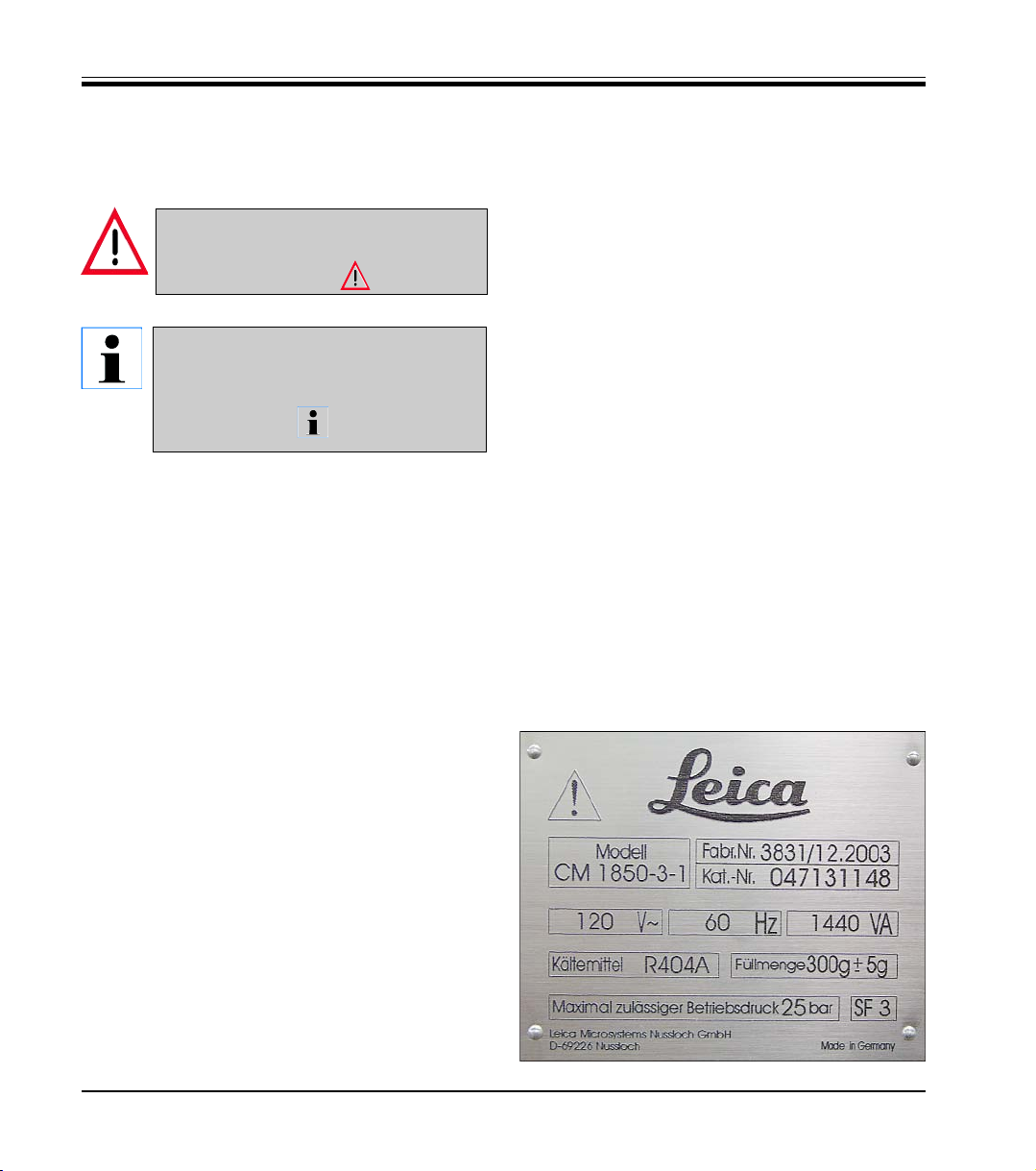
1.4 Instrument type:
All information given in this instruction manual
applies only to the instrument type indicated
on the title page.
A name plate, indicating the instrument serial
number, is attached to the back of the instrument.
Fig. 1
6
Instruction Manual V 2.2 – 12/2003
Page 7
2.1 Safety features
2. Safety
This instruction manual includes important instructions and information
related to the operating safety and maintenance of the instrument.
The instruction manual is an important part of the product. It must be
read carefully before using the instrument for the first time and must
always be kept with the instrument.
If additional requirements, which exceed the scope of this manual, are
imposed by regulations and/or laws on accident prevention and environmental protection in the country of operation, appropriate instructions for compliance with such requirements must be added to this
manual.
Read this instruction manual carefully before attempting to use or operate the instrument.
The instrument and its accessory equipment incorporate the following
safety features: safety handwheel and knife guards on the knife holders.
The consistent use of these safety features and strict observation of the
warnings and cautions in this manual, will safeguard the operator from
accidents and/or personal injury to a great extent.
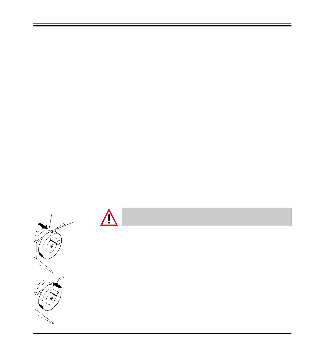
2.1.1 Locking the handwheel
2
1
For locking the handwheel rotate the handle until it is in the upper position.
Push the locking pin (1) into the recess at the handwheel. The locking posi-
tion is marked by a black dot (2). If necessary, move the handwheel slightly
Fig. 2
Fig. 3
Leica CM1850 – Cryostat
forth and back until the locking mechanism engages.
To unlock, push the locking pin (1) to the left from the recess at the handwheel.
Prior to manipulating the knife and specimen, or changing the
specimen or knife, and during breaks, always lock the handwheel!
7
Page 8
2. Safety
2.1.2 Knife guard
For every manipulation in the cryochamber, or upon changing a
specimen when the knife or disposable blade is clamped, or during breaks, cover the cutting edge with the knife guard.
The knife holders CN and CS are equipped with knife guards; on the knife
holder CE the glass plate of the anti-roll guide constitutes the knife guard
(please refer to the separate instruction manual for your knife holder).
Prior to manipulating the knife and specimen, or changing the specimen
or knife, and during breaks, always lock the handwheel!
2.2 General information on instrument design and safe handling
This instrument has been built and tested in accordance with the following safety regulations on electrical measuring, control, regulating and
laboratory devices:
• DIN EN 292,
• DIN EN 61010-1,
• EN 50082-1,
• EN 55011,
• IEC 1000-4
as well as according to the international quality standard,
• DIN ISO 9001.
In order to maintain this condition and to ensure safe operation, the operator must observe the instructions and warnings contained in this instruction manual.
8
Instruction Manual V 2.2 – 12/2003
Page 9

2.3 Operating conditions Transport and installation
• After transporting do not turn the instrument on for a minimum of 4
• Do not operate in rooms with explosion hazard!
• To ensure an adequate cooling capacity, the instrument must be set
Connection to mains
• Before connecting to the mains power, please check if the local volt-
• During the compressor start-up the nominal voltage must not drop
• After transporting, wait at least 4 hours before turning the instrument
Defrosting
2. Safety
hours!
up with at least 10 cm distance from walls and furniture!
age complies with the power rating specified on the name plate of
the instrument!
below the values specified in the ‘Technical data‘!
The compressor requires a start-up current between 45 and 50 A.
Therefore, the electric circuit at the place of installation must be inspected by an electrical engineer to ensure that it meets the requirements for a smooth operation of the instrument.
A constant adequate power supply to the instrument must be ensured at all times.
Failure to comply with the above will cause severe damage to the
instrument.
on.
This waiting period is necessary to allow the compressor oil, which
may have been displaced during transport, to return to its original
position.
Failure to comply with this can cause severe damage to the instrument.
• The quick freeze shelf may become hot during defrosting!
Therefore, do not touch it!
2.4 Operating the instrument
• Take care when handling microtome knives and disposable blades.
The cutting edge is extremely sharp and can cause severe injury!
Leica CM1850 – Cryostat
9
Page 10

2. Safety
• Never leave knives and knife holders with a knife/blade mounted
lying around!
• Do not place a knife on a table with the cutting edge facing upward!
• Never try to catch a falling knife!
• Always clamp the specimen before the knife!
• Prior to manipulating the knife and specimen, or changing the specimen or knife, and during breaks, always lock the handwheel and
cover the cutting edge with the knife guard!
• Avoid contact with cold parts of the instrument as this can cause
frostbite!
• To make sure that the condensation water stemming from the defrost cycles drains into the waste container and to avoid the risk of
possible contaminations, ensure that the tap of the waste container
(2, Fig. 31.1) is open when operating the instrument. Only shut the tap
when draining the waste container!
2.5 Cleaning and disinfection
• It is not necessary to remove the microtome for routinely disinfecting
the cryochamber.
The instrument is appropriate for spray disinfection with Leica
Cryofect!
• Do not use organic solvents or any other aggressive substances for
cleaning and disinfection!
Only use the cleaning agents and disinfectants specified in this instruction manual such as Leica Cryofect (alcohol or common disinfectants based on alcohol)!
2.6 Removal of the microtome
• Prior to removing the microtome, turn the instrument off with the mains
switch and pull the mains plug.
• Prior to removing the microtome, bring the specimen head to the lower
position with the handwheel.
Otherwise the specimen head would rapidly fall down and might injure the operator‘s hands, when taking out the microtome.
• Wear appropriate protective gloves to take the cold microtome out of
the cryochamber.
10
Instruction Manual V 2.2 – 12/2003
Page 11

.2.7 Maintenance
Replacement of the fuses
2. Safety
Extended skin contact with cold parts of the instrument may cause
frost bite!
• The microtome must be entirely dry before reinstallation. Humidity
inside will condense and freeze in the cold cryostat and thus cause
malfunctions or damage.
• Do not use external heaters for drying the cryochamber. This can
cause damage to the cooling system!
• All components removed from the cryostat must be carefully dried
before they are replaced in the cryochamber
• Turn the instrument off with the automatic mains fuse and pull the
mains plug, before replacing the fuses.
• Only use fuses of the same specification! For the required values,
please refer to Chapter 3 ‘Technical data‘.
The use of fuses other than specified by the manufacturer may cause
severe damage to the instrument!
Replacement of the lamp
Leica CM1850 – Cryostat
• Turn the instrument off with the automatic mains fuse and pull the
mains plug, before replacing the lamp.
• If the lamp is broken, it must be replaced by the technical service, as
the replacement involves a high risk of injury.
11
Page 12

3. Technical data
Operating temperature range (ambient temperature): 18 °C to 40 °C.
All specifications related to temperature are valid only up to an ambient temperature of 22 °C
and an air humidity lower than 60%!
Type CM1850 CM1850 CM1850-08 CM1850-01
Mark of conformity CUL - - VDE
Nominal voltage (±10%) 120 V AC 220 V AC 230 V AC 240 V AC
Nominal frequency 60 Hz 60 Hz 50 Hz 50 Hz
Power draw 1600 VA 1600 VA 1600 VA 1600 VA
Max. start-up current for 5 sec 45A eff. 45A eff. 45A eff. 45A eff.
Protective class I I I I
Automatic mains fuse T12A T1 T12A T1 T10A T1 T10A T1
Pollution degree 2 2 2 2
Overvoltage installation category
Heat emission (max.) 1600 J/s 1600 J/s 1600 J/s 1600 J/s
Refrigeration system 50 Hz 60 Hz
Cryochamber
Temperature setting range 0°C to -35°C (+ 2 K / - 0 K) 0°C to -35°C (+ 2 K / - 0 K)
Defrosting automatic hot gas defrosting, automatic hot gas defrosting,
Refrigeration capacity 690 W 690 W
Safety factor 3 3
Refrigerant 300 g ±5g refrigerant R 404A * 300 g ±5g refrigerant R 404A *
Compressor oil 0.6 l EMKARATE RL-22S, ICI * 0.6 l EMKARATE RL-22S, ICI *
II II II II
temperature controlled temperature controlled
1 automatic defrost cycle/24 hours, 1 automatic defrost cycle/24 hours,
temperature controlled temperature controlled
manual defrost cycle manual defrost cycle
Quick freeze shelf
Max. temperature -40°C (+ 0 K / - 2 K) - 40°C (+ 0 K / - 2 K)
Number of quick freeze stations 10 10
Defrosting manual hot gas defrosting manual hot gas defrosting
time controlled time controlled
Peltier element (option)
Max. temperature -60°C (+5 K) -60°C (+5 K)
Number of freezing stations 2 2*
Defrosting together with quick freeze shelf together with quick freeze shelf
12
Instruction Manual V 2.2 – 12/2003
Page 13
3. Technical data
* Refrigerant and compressor oil must only be replaced by qualified, authorized service personnel!
Microtome
Rotary microtome
Section thickness setting 1 - 60 µm
Specimen feed 25 mm
Vertical stroke 59 mm
Maximum specimen size 55 x 55 mm
Specimen orientation 8° (x-, y-, z-Achse)
Electric coarse feed
slow 0.2 mm/s
rapid 0.7 mm/s
Cryocabinet
Dimensions
Width (w/o handwheel) 600 mm
Width (with handwheel) 730 mm
Depth 730 mm
Height 1140 mm
Weight (incl. microtome,
without specimen cooling) approx.135 kg
Fluorescent lamp
50 Hz version: Osram Dulux S 11 W/21
Color: LUMILUX light white
60 Hz version: Osram Dulux S 13 W/21
Color: LUMILUX light white
➀ according to IEC-1010, UL 3101
➁ according to CECOMAF
Liquid temperature 45°C
Evaporation temperature -25°C
Please refer to section 5.2 ‘Site requirements‘!
All CM 1850 types require the following fuses:
F1: T0,25 A Fa. Schurter, Typ FST; 6,3x32 mm or T0,25 A Fa. Littlefuse, Typ 313; 6,3x32 mm
F2: T0,6 A Fa. Schurter, Typ FST; 6,3x32 mm or T0,6 A Fa. Littlefuse, Typ 313; 6,3x32 mm
F3: T1,6 A Fa. Schurter, Typ FST; 6,3x32 mm or T1,6 A Fa. Littlefuse, Typ 313; 6,3x32 mm
F4: T6,25 A Fa. Schurter, Typ FST; 6,3x32 mm or T6,25 A Fa. Littlefuse, Typ 313; 6,3x32 mm
F5: T4 A Fa. Schurter, Typ FST; 6,3x32 mm or T4 Fa. Littlefuse, Typ 313; 6,3x32 mm
Leica CM1850 – Cryostat
13
Page 14
4. Unpacking and installation
4.1 Site requirements
Do not operate in rooms with explosion hazard!To ensure an adequate cooling capacity, the instrument must be set up with at
least 10 cm distance from walls and furniture.
• The place of installation must meet the following requirements:
– no direct sunlight,
– mains power socket at a distance no greater than approxi-
mately 1.5 m,
– no drafts (air condition outlets, etc.) directly over the instrument,
– even floor,
– mainly vibration-free floor,
– obstruction-free access to the handwheel,
– room temperature max. 35°C,
– Air humidity must not exceed 60% High room temperatures and ex-
cessive air humidity affect the cooling capacity of the cryostat.
High room temperatures and excessive air humidity affect the
cooling capacity of the cryostat.
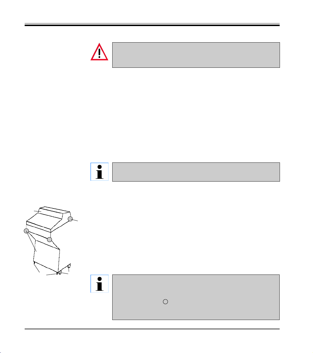
4.2 Transport to the desired location
• Move the instrument to the installation site on its wheels (14). Please
note the areas which are reinforced for tarnsporting and grip the
Tilt
cabinet only at these locations (Fig. 4).
• The adjustable feet (15) can support the weight of the instrument
when tipping at a slight angle (max. 30 °).
• At the installation site unscrew the screws in the adjustable feet (15)
using a fork wrench.
This is necessary to ensure stability.
• Align the adjustable feet to level the instrument.
The instrument must be transported in an upright position only.
When the instrument is tilted, the compressor oil is displaced.
Do not grip the cabinet at the lid. Grip the cabinet only at the
marked locations ( ).
The alignment of the adjustable feet is necessary to ensure an
unobstructed drain of the quick freeze shelf defrosting water.
Fig. 4
16
Lengthwise
movement
Sideways
movement
15
14
14
Instruction Manual V 2.2 – 12/2003
Page 15

4. Unpacking and installation
4.3 Standard delivery
It gives following variations: - CM1850 with Retraction ............................................. 0471 31150
- CM1850 without Retraction (only US) ..................... 0471 31148
1 Handwheel, assy. ......................................................................................... 0416 18478
1 Heat extractor, stationary ......................................................................................... 0471 30792
1 Low temperature stabilizer for heat extractor, (Parking station) ................................... 0471 30793
1 Optional clamping lever for object head ............................................................................. 0112 28806
3 Specimen discs, 25mm diameter ......................................................................................... 0416 19275
1 Section waste tray ......................................................................................... 0471 30787
1 Storage shelf, right ......................................................................................... 0471 30789
1 Storage shelf, left ......................................................................................... 0471 30790
1 Brush, fine ......................................................................................... 0183 28642
1 Leica brush ......................................................................................... 0183 30751
1 Brush shelf ........................................................................................ (0398 13088
1 Tool set:
- 1 Allen key, size 2.5 ......................................................................................... 0222 04137
- 1 Allen key, size 3 ........................................................................................ 0222 04138
- 1 Allen key with spherical head, size 4 ............................................................................. 0222 32131
- 1 Allen key, size 6 ......................................................................................... 0222 04141
- 1 Single-head wrench, size 16 ......................................................................................... 0330 18595
1 Bottle of cryostat oil, type 407, 50 ml ..................................................................................... 0336 06098
1 Bottle of OCT-Compound, mounting medium for cryosectioning, 125 ml ..................... 0201 08926
1 Instruction manual Leica CM1850 - G/E/F/S ........................................................................ 0708 37106
Leica CM1850 – Cryostat
Compare the delivered components with the parts list and your order.
Should you find any discrepancies, please contact your Leica sales office without delay.
A choice of different knife holders is available for the CM 1850.
The knife holder is accompanied by its own separate instruction
manual.
Please contact your Leica sales office if the instruction manual
is missing.
15
Page 16

4. Unpacking and installation
4.4 Handwheel assembly
1
2
• Insert the pin (1) of the handwheel shaft in
to the hole (2) of the handwheel.
Fig. 5
3
4
5
• Mount the spring washer (3) on the screw (4)
as shown in Fig. 16.
• Tighten the screw (4) with an Allen key (5 mm).
• Attach the cover disc (5) (self-adhesive).
To dismount, proceed in reverse order.
The handwheel including the fixing components are packed in the
cardboard box for the accessories.The handwheel can be dismounted for transporting (e.g. narrow doors).
16
Instruction Manual V 2.2 – 12/2003
Page 17

5.1 Connection to mains power
• The electric circuit at the place of installation must be protected separately.
• Do not connect any other consumers to this electric circuit.
5.2 Prior to operation
• Before connecting the instrument to the mains power, please check if
the local mains voltage complies with the power rating indicated on the
name plate of the instrument.
5. Setup
During the start-up of the compressor the nominal voltage must not
drop below the values specified in the ‘Technical data‘.
Please note that the compressor requires a start-up current between 45 and 50 A.
Therefore, the electric circuit at the installation site must be inspected by an electrical engineer to ensure that it meets the requirements for a smooth operation of the instrument.
A constant adequate power supply to the instrument must be ensured at all times.
Failure to comply with the above will cause severe damage to the
instrument.
Leica CM1850 – Cryostat
• Place the storage shelves in the cryochamber.
• Place the section waste tray and brush shelf in the cryochamber.
• Place the knife holder base on the microtome base plate.
• Insert the knife holder and clamp it on the base plate For details, please
refer to the separate instruction manual for your knife holder).
• Open the knife box with the knife and place it in the cryochamber for
precooling.
• Place all tools needed for specimen preparation in the cryochamber.
• Close the sliding window.
• Connect the mains plug to the mains power outlet at the wall.
17
Page 18

5. Setup
5.3 Leica CM1850 - Overview
17
13
15
4
16
21
Fig. 6
18
20
8
13
12
19
18
10
14
9
13
11
Instruction Manual V 2.2 – 12/2003
Page 19

5. Setup
3
5
6
1 Cryostat CM1850
2 Waste container
3 Control panel 1
4 Control panel 2
5 Storage shelf, left
6 Storage shelf, right
7 Automatic mains fuse
8 Support for stationary heat
7
extractor (accessory)*
9 Quick freeze shelf
10 Peltier element (accessory)
11 Parking station (accessory)*
12 Stationary heat extractor
(accessory)*
13 Specimen disc
14 Thermal bloc (accessory)
15 Section waste tray
16 Brush shelf
17 Orientable specimen head
2
1
18 Knife holder base (accessory)
19 Knife holder CE (accessory)
20 Knife holder CN (accessory)
21 Knife holder CS (accessory)
Leica CM1850 – Cryostat
*) included in the standard delivery
range of models with Peltier
element
19
Page 20

5. Setup
5.4 Mains switch and automatic mains fuse
The automatic mains fuse is used as mains switch.
To turn the automatic mains fuse on, the switch must be set in the upper
position (pos. 1).
To turn the automatic mains fuse off, the switch must be set in the lower
position (pos. 0).
Fig. 7
Automatic mains fuse
5.5 Turning the instrument on
After transporting, wait at least 4 hours before turning the instrument on.
This waiting period is necessary to allow the compressor oil,
which may have been displaced during transport, to return to its
original position.
Failure to comply with this can cause severe damage to the instrument.
20
• Turn the instrument on with the automatic mains fuse.
• The instrument has been configured ex works as follows:
Time: 00:00
Defrost time: 10:00
Cryochamber cooling: On
(Indication of the temperature)
Peltier element (option): Off
Indication ‘PE‘
without Peltier element: Indication ‘LL‘
• Set the desired values as described in the sections 6.2.1 to 6.2.3.
During normal operation pressure compensation prior to the compressor start-up might lead to a hissing sound.
Instruction Manual V 2.2 – 12/2003
Page 21

6.1 Control panel 1
Fig. 8
6. Control panel operation
Function keys
Lamp button
ON/OFF switch for cryochamber illumination.
Manual defrost button
To activate and deactivate manual defrosting.
Key button
To lock and unlock the control panel to protect the entered parameters from
unintended modifications. To lock or unlock, hold down for approximately 5
seconds.
6.2 Programming the desired values
6.2.1 Setting the time
The actual time is set on the panel marked with the clock symbol using the
and keys.
When pushing the or button for more than 1 second, the time value
increases or decreases continuously (autorepeat function).
Fig. 9
Leica CM1850 – Cryostat
21
Page 22

6. Control panel operation
6.2.2 Setting the automatic defrost time (cryochamber)
The automatic defrost cycle takes place once within 24 hours.
Touch the or button for indication of the beginning of the defrost cycle
which has actually been set. At the same time, the LEDs between the indication of hours and minutes are flashing.
To change the beginning of the defrost cycle in steps of 15 minutes, push
Fig. 10
6.2.3 Selecting the cryochamber temperature
Fig. 11
the or button.
The temperature of the cryochamber is set and indicated on the panel marked
with the cryostat symbol.
The actual temperature is the standard indication.
For indication of the desired value, touch the or button.
Set the desired value with the and buttons. When pushing the or
bu tton for more than 1 second, the chamber temperature value increases
or decreases continuously.
The actual value will be indicated 5 seconds after finishing the programming.
22
Instruction Manual V 2.2 – 12/2003
Page 23

6.2.4 Activation of the Peltier element (option)
The Peltier element is used for cooling the quick-freeze stations. Upon activation of the Peltier element, the compressor of the cooling system is started
after 40 seconds to reinforce the thermal conductivity effect.
Display reading of instruments
without Peltier element: ‘LL‘
Fig. 12
with Peltier element: ‘PE‘
The Peltier element is activated by pressing .
Once activated, the display indication changes to ‘10‘ (i.e. the Peltier element will operate for 10 minutes). The countdown of the remaining cooling
time is permanently displayed.
The Peltier element turns off automatically after 10 minutes.
Once the remaining cooling time displayed is 4 minutes, the figure 4 is followed by a point (‘ 4. ‘). At this stage the Peltier element may be deactivated
by pressing again.
Once deactivated, the display indication returns to ‘PE‘.
6.2.5 Manual defrosting of the quick freeze shelf
6. Control panel operation
Fig. 13
Leica CM1850 – Cryostat
The quick freeze shelf may become hot during defrosting!
Therefore, do not touch it!
The manual defrosting of the quick freeze shelf is activated by subsequently
pressing the button (audible signal turns on) and the key (audible
signal turns off). During the defrost cycle, the indication is flashing.
To turn off the manual defrosting cycle of the quick freeze shelf prior to the
automatic deactivation, press again and .
Quick freeze shelf and cryochamber defrosting can be run independently. However, it is not possible to defrost both systems simultaneously.
23
Page 24

6. Control panel operation
6.2.6 Manual defrosting of the cryochamber
The manual defrosting of the cryochamber is activated by subsequently
pressing the button (audible signal turns on) and the or button on
the panel for the cryochamber temperature (audible signal turns off). During
the defrost cycle, the indication is flashing.
If you want to turn off the manual defrosting of the quick freeze shelf prior to
the automatic deactivation, press again and or on the panel for
the cryochamber temperature.
Fig. 14
6.3 Display lock
The programmed values cannot be modified after having pushed the key
button.
Push the key button once more for 5 seconds to unlock the display.
Fig. 15
24
When the display is locked, the LEDs between the hour and minute indication on the time panel are turned off.
Instruction Manual V 2.2 – 12/2003
Page 25

6.4 Control panel 2 - Electric coarse feed
Move the specimen away from the knife
• Press to start a rapid return travel of the specimen to the rear limit.
LED (1) flashes, while the specimen head is in motion.
6. Control panel operation
1
On reaching the rear limit, the LED (1) starts illuminating.
• The return movement can be stopped by pressing one of the coarse feed
buttons.
• Press to start a slow return movements of the specimen to the rear limit.
The specimen will slowly move to the rear limit, as long as the button is
held down.
Move the specimen towards the knife
• Press to start a rapid or slow advance of the specimen towards the knife.
The advance movement operates as long as the button is pressed. This
rapid
2
slow
is a safety feature to protect both the specimen and knife from damage!
On reaching the front limit, the LED (2) of the button starts illuminating.
Leica CM1850 – Cryostat
25
Page 26

7. Daily use of the instrument
7.1 Specimen freezing
• Select the appropriate sectioning temperature (cryochamber temperature) for the sample material (please refer to 7.4 Temperature selection
chart‘).
7.1.1 Quick freeze shelf
The cryochamber has a quick freeze shelf (5, Fig. 17) for up to 10 specimen discs.
The temperature of the quick freeze shelf is always lower than the cryochamber
1
temperature.
2
5
• Cut the specimen to size.
• Activate the Peltier element (4) (option), if
available - it may take up to 40 seconds until
the maximum refrigeration output is available.
• Apply enough cryocompound to a specimen
disc at room temperature.
• Place the specimen on the disc and orient.
• Place the specimen disc in one of the holes of
the quick freeze shelf and freeze the specimen
at a low temperature.
• Once the specimen is frozen, insert the
specimen disc in the specimen head
(Fig. 18) and start sectioning.
Fig. 17
4
3
7.1.2 Stationary heat extractor (accessory)*
• Fix the support (1) of the heat extractor (2) by tightening the 2 screws to
the threaded holes on the left sidewall of the cryochamber and insert the
heat extractor.
• Lower the heat extractor cylinder on the specimen surface. After approximately 30 seconds contact, the specimen will be entirely frozen.
• Once the specimen is frozen, place the heat extractor on the parking
station (3).
*) included in models with Peltier element
26
Instruction Manual V 2.2 – 12/2003
Page 27

7. Daily use of the instrument
7.2 Specimen discs 7.2.1 Inserting the specimen discs in the
specimen head
• Lock the handle of the handwheel in the upper
position.
• If the knife holder and a knife are in place,
cover the knife edge with the knife guard.
• Loosen the screw (1) on the specimen head.
• Insert the shaft of the specimen disc (3) in the
location hole (2) of the specimen head.
Make sure that the shaft of the specimen disc is
fully inserted. The entire rear surface of the prism
must have a good contact with the specimen
head.
Fig. 18
• Retighten screw (1).
7.2.2 Specimen orientation
• To release, loosen screw (4).
• Orient the specimen surface with lever (5).
• Retighten screw (4).
Leica CM1850 – Cryostat
27
Page 28
7. Daily use of the instrument
7.3 Sectioning
All necessary adjustments on the knife holder and anti-roll guide
are described in the separate instruction manual for your knife
holder in detail.
7.3.1 Trimming the specimen
Take care when handling microtome knives and disposable
blades. The cutting edge is extremely sharp and can cause severe
injury!
• Insert the precooled knife/blade in the knife holder and clamp.
• Adjust the appropriate clearance angle on the knife holder. Adjustments between 4 ° and 6 ° (knife
holder CN and CS) or between 1 ° and 2 ° (knife holder CE) are suitable for most applications.
• Align the knife holder/knife with the specimen.
• Remove the knife guard (knife holder CN, CS) or fold the glass anti-roll guide (knife holder CE) over
to the left.
• Unlock the handwheel.
• Trim the specimen to shape approach the specimen towards the knife by means of the coarse feed
buttons. Trim the specimen down to the required sectioning plane by turning the handwheel.
• Position the anti-roll guide on the knife and align with the cutting edge.
Readjust the anti-roll plate if necessary.
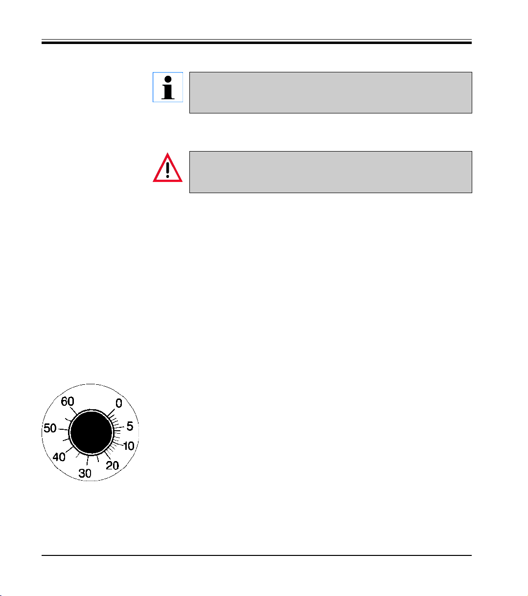
7.3.2 Section thickness setting
The section thickness is adjusted in a range of 1 to 60 µm by turning the knob
(1) :
f rom 0 - 10 µm in 1 µm increments,
from 10 - 20 µm in 2 µm increments, from 20 - 60 µm in 5 µm increments.
The selected section thickness is indicated on the index mark on the
microtome.
• Select the required section thickness with the control knob on the
microtome.
Start sectioning at approximately 20 µm.
• Decrease the section thickness continually down to the appropriate value.
After changing from one section thickness to another, the first two or three sections should
berejected.
• When sectioning, turn the handwheel at a constant speed.
28
Instruction Manual V 2.2 – 12/2003
Page 29

7. Daily use of the instrument
7.4 Temperaturew selection chart (in minus °C)
Tissue -10°C – -15°C -15°C – -25°C -25°C – -35°C
Adrenal ❄❄
Bone marrow ❄
Brain ❄
Bladder ❄
Breast - fatty ❄
Breast - little fat ❄
Cartilage ❄❄
Cervical ❄
Fatty ❄
Heart and vascular ❄
Intestinal ❄
Kidney ❄
Laryngeal ❄
Lip ❄
Liver ❄
Lung ❄
Lymphoid ❄
Muscular ❄
Nose ❄
Pancreatic ❄
Prostate ❄
Ovarian ❄
Rectal ❄
Skin with fat ❄
Skin without fat ❄
Spleenal or bloody tissue ❄
Testicular ❄❄
Thyroid ❄
Tongue ❄
Uterus curettage ❄
The temperature values given above are based on long-term experience, however, these are only approximate values,
as any tissue may require particular adjustments.
Leica CM1850 – Cryostat
29
Page 30

7. Daily use of the instrument
7.5 Defrosting
Defrosting the cryochamber actually means defrosting the evaporator to
prevent excessive frost buildup. The evaporator is flushed with hot gas during defrosting. The cryochamber virtually is frostfree and does not need to
be defrosted.
The condensation water that is produced during defrosting is collected in a
container, which is located at the front of the cryostat cabinet.
To make sure that the condensation water stemming from the defrost cycles drains into the waste container and to avoid the risk of
possible contaminations, ensure that the tap of the waste container (2, Fig. 41) is open when operating the instrument. Only
shut the tap when draining the waste container!
The quick freeze shelf is cooled during the automatic cryochamber
defrosting. However, the Peltier element is turned off.The maximum duration of a defrost cycle is 12 minutes. Defrosting is terminated automatically once the cryochamber has reached a temperature of -5 °C.
Cooling turns back on automatically.
7.5.1 Automatic defrosting of the cryochamber
An automatic defrost cycle takes place once in 24 hours.
The time of the automatic defrost cycle is programmed via the control panel
1 (see 6.2.1 and 6.2.2).
7.5.2 Manual defrosting of the cryochamber
In addition to the programmable automatic defrost cycle a manual defrost
cycle can be activated (see also 6.2.6).
To avoid an unintended defrosting, the activation of a manual defrost cycle is confirmed by an audible signal.
Cooling turns back on automatically.
30
Instruction Manual V 2.2 – 12/2003
Page 31

7.5.3 Manual defrosting of the quick freeze shelf
The quick freeze shelf may become hot during defrosting!
Therefore, do not touch it!
If increased frost formation occurs on the quick freeze shelf, especially after spray disinfection, a manual defrost cycle should be started (see 6.2.5),
which can be terminated when required.
7.6 Terminating work
7.6.1 Terminating daily work
• Lock the handwheel.
• Take the knife out of the knife holder and put it back into the knife box in
the cryochamber.
• Remove frozen section waste with a cold brush.
• Empty the section waste tray.
• Clean the storage shelves and brush shelf.
7. Daily use of the instrument
Leica CM1850 – Cryostat
Only common detergents and disinfectants that contain 95 - 98%
alcohol should be used for cleaning.
All components removed from the cold environment will collect
condensation. Therefore, dry them thoroughly before placing them
back into the cryochamber.
• Remove all specimens from the cryostat.
• Close the sliding window.
• Turn out the cryochamber illumination.
• Lock control panel 1 (Fig. 8) with the KEY button.
• Do not turn the instrument off with the automatic mains fuse as there
would be no cooling.
31
Page 32

8. Troubleshooting
7.6.2 Shutdown for a longer period
If you do not intend to use the instrument for several weeks you
may turn it off.
Please note, however, that it may take up to several hours to cool
the cryochamber down to very low temperatures after turning the
instrument on again.
After turning off, the instrument should be cleaned and disinfected
thoroughly (see chapter 9 ‘Cleaning, disinfection and maintenance').
• Turn the instrument off with the automatic mains fuse.
• Open the sliding window to allow the cryochamber to dry.
• Remove all the specimens from the cryostat.
• Lock the handwheel.
• Take the knife/blade out of the knife holder. Put the knife back into the
knife box or push the blade into the receptacle for used blades provided
at the bottom of the dispenser.
• Remove all section waste with a cold brush.
• Empty the section waste tray and remove it for cleaning and disinfection.
• Remove the storage shelves and the brush shelf for cleaning and disinfection.
Turning off the instrument with the automatic mains fuse will not affect the
programmed parameters.
Before turning the instrument on again, the cryochamber microtome and all
accessory components must be absolutely dry.
32
Instruction Manual V 2.2 – 12/2003
Page 33

8. Troubleshooting
8.1 Error messages in the display
Error messages are displayed on the clock panel as follows: EO: XX. The
following error messages might occur during operation:
Fig. 20
Error Description Remedy
20 Calibrating error; possibly defective controller board. Turn the instrument on again.
If the error is displayed again:
Call service.
21 Clock battery on the controller board empty. Call service.
22 Microtome wet. Dry microtome.
23 Cryochamber temperature out of range of indication. Remove cause.
(from -35 °C to +55 °C)
24 Short circuit at the temperature sensor Call service.
of the chamber cooling system.
25 Breaking of the temperature sensor Call service.
of the chamber cooling system.
26 Short circuit at the temperature sensor of the evaporator. Call service.
27 Breaking of the temperature sensor of the evaporator. Call service.
8.2 Temperature control button
On the back of the cryostat cabinet there is a temperature control button (1). If the temperature of the
cryochamber exceeds 60 °C the switch is automatically activated and turns the instrument off.
Possible causes and remedies:
• Temperature of the direct surroundings is
constantly higher than 40 °C.
-->Drop the temperature of the direct surroundings.
• When setting up the instrument the minimum
distance of 10 cm to walls and furniture was
not kept.
--> Keep the minimum distance.
• The ventilation slits of the liquefier are dirty.
Fig. 21
After eliminating the possible source of error, push the temperature control button (1) to turn the instrument back on. If the instrument fails to turn on, make a service call.
Leica CM1850 – Cryostat
--> Clean the ventilation slits (see 9.3.1).
33
Page 34

8. Troubleshooting
8.3 Possible causes and remedies
Problem Cause Remedy
Frost on chamber walls and microtome
Ice formation on the bottom of
the cryochamber
Sections smear
Sections splinter
Sections not properly flattened
- Cryostat is exposed to air currents (open windows and
doors, air conditioning).
- Sliding window was open and
exposed to air currents too
long.
- Frost built up by breathing into
the cryochamber.
- Condensation water drain obstructed.
- Drain of the quick freeze shelf
defrosting water obstructed.
- Specimen not cold enough.
- Knife/blade and/or anti-roll
plate not yet cold enough and
thus warm the sections.
- Specimen too cold
- Static electricity/air currents.
- Specimen not cold enough.
- Large area specimen.
- Anti-roll plate poorly positioned.
- Anti-roll plate poorly aligned
with knife edge.
- Incorrect clearance angle.
- Knife/blade blunt or damaged.
- Change place of installation for
the cryostat.
- Open the tap of the drain tube
(2, Fig. 31), switch off the instrument and let it thaw and dry.
- Align the instrument with a
spirit level.
- Select lower temperature.
- Wait until knife/blade and/or
anti-roll plate have reached
chamber temperature.
- Select higher temperature.
- Remove cause.
- Select lower temperature.
- Trim the specimen parallel,
increase section thickness.
- Reposition anti-roll plate.
- Align correctly.
- Set correct angle.
- Use different part of the cutting
edge or replace.
34
Instruction Manual V 2.2 – 12/2003
Page 35

8. Troubleshooting
Problem Cause Remedy
Sections not properly flattened
despite correct temperature and
correctly aligned anti-roll plate
Sections curl on the anti-roll
plate
Scraping noise during sectioning
and specimen return movement
Ridged sections
Chatter during sectioning
- Knife/blade and/or anti-roll
plate dirty.
- Edge of anti-roll pate damaged.
- Blunt knife/blade.
- Anti-roll plate does not protrude far enough beyond the
cutting edge.
- Anti-roll plate protrudes too far
beyond the cutting edge and is
scraping against the specimen.
- Knife/blade damaged.
- Edge of anti-roll plate damaged.
- Specimen insufficiently frozen
onto the specimen disc.
- Specimen disc not clamped
tightly.
- Specimen holder ball joint not
clamped.
- Knife/blade not clamped tightly
enough.
- Specimen has been sectioned
too thickly and has detached
from the disc.
- Very hard, inhomogeneous
specimen.
- Blunt knife/blade.
- Clean with dry cloth or brush.
- Replace plate.
- Use different part of the cutting
edge or replace.
- Readjust correctly.
- Readjust correctly.
- Use different part of the cutting
edge or replace.
- Replace the plate.
- Refreeze specimen onto the
disc.
- Check disc clamping.
- Check ball joint clamping.
- Check knife/blade clamping.
- Refreeze specimen onto the
disc.
- Increase section thickness;
reduce specimen surface area
if necessary.
- Use different part of the cutting
edge or replace the knife/
blade.
Leica CM1850 – Cryostat
35
Page 36

8. Troubleshooting
Problem Cause Remedy
Condensation on anti-roll plate
and knife during cleaning
Anti-roll plate damage after adjustment
Thick-thin sections
- Knife profile inappropriate for
the specimen to be cut.
- Incorrect clearance angle.
- Brush, forceps and/or cloth are
too warm.
- Plate too high above the cutting edge. The adjustment was
carried out in the direction of
the cutting edge.
- Temperature incorrect for the
tissue cut.
- Knife profile inappropriate for
the specimen cut.
- Ice buildup in the knife back.
- Handwheel speed not uniform.
- Knife/blade not clamped tightly
enough.
- Specimen holder not clamped
tightly.
- Cryocompound applied to cold
specimen disc; specimen detached from the disc after
freezing.
- Blunt cutting edge.
- Incorrect clearance angle.
- Microtome not properly dried
before reinstallation.
- Dried specimen.
- Use knife with different profile.
- Set correct angle.
- Store all tools on shelf in the
chamber.
- Raise plate when aligning.
- Be more careful next time.
- Select correct temperature.
- Wait until the correct temperature is reached.
- Use knife with different profile
(c or d).
- Remove ice.
- Adapt speed.
- Check knife/blade clamping.
- Check clamping.
- Apply cryocompound on warm
disc; mount specimen and
freeze.
- Use different part of the cutting
edge or replace the knife/
blade.
- Set correct angle.
- Dry microtome thoroughly.
- Prepare new specimen.
Tissue sticks or crumbles on the
anti-roll plate
36
- Anti-roll plate is too warm or
incorrectly positioned.
- Static electricity.
- Cool down anti-roll plate or
reposition plate.
- Remove static electricity.
Instruction Manual V 2.2 – 12/2003
Page 37

8. Troubleshooting
Problem Cause Remedy
Flattened sections curl up when
anti-roll plate is picked up
Sections tear
Inconsistent or insufficient specimen feed
Specimen disc cannot be removed
Fat on the corner or edge of the
anti-roll plate.
- Rusty knife/blade.
- Static electricity or air currents.
- Anti-roll plate too warm.
- Temperature too low for the
tissue cut.
- Blunt part, dirt, dust, frost or
rust on the knife/blade.
- Leading edge of anti-roll plate
damaged.
- Hard particles in the tissue.
- Knife back dirty.
- Microtome was not entirely dry
when switching on refrigeration; consequently ice built up
in the micrometer feed system.
- Defective microtome.
- Moisture on the underside
caused the disc to freeze to the
freezing shelf or specimen
head.
- Remove fat with alcohol.
- Remove rust.
- Remove static electricity.
- Cool down the anti-roll plate.
- Increase temperature and
wait.
- Remove cause.
- Replace the plate.
- - -
- Clean.
- Remove the microtome and
dry it thoroughly before reinstallation.
- Call technical service.
- Apply concentrated alcohol to
the contact point or heat the
specimen head.
Cryostat inoperational
Leica CM1850 – Cryostat
- Mains plug not properly connected.
- Defective fuses.
- Temperature control switch
activated.
- Check the mains plug is properly connected.
- Replace the fuses.
- Check site conditions as described in section 5.2, and
reset the temperature control
switch.
37
Page 38

8. Troubleshooting
Problem Cause Remedy
No or insufficient refrigeration
Scraping noise at the microtome
- Compressor defective.
- Leak in the cooling system.
- Inappropriate site conditions.
- Ventilation slits of the liquefier
dirty.
- Friction between the slot cover
and the microtome housing.
- Call technical service.
- Call technical service.
- Check site conditions as described in section 5.2.
- Clean the ventilation slits as
described in section 10.3.1.
- Apply cryostat oil to the slot
cover and distribute by turning
the handwheel or with a cloth.
38
Instruction Manual V 2.2 – 12/2003
Page 39

9.1 Cleaning
2
3
9. Cleaning, disinfection, maintenance
• Remove frozen section waste from the cryostat with a cold brush every
day.
• Remove the section waste tray for emptying.
• Remove the storage shelves and the brush shelf for cleaning.
• Remove the sliding window by slightly lifting and pulling it to the front
when closed (see 9.3.6 'Replacement of the lamp').
Do not use organic solvents or any other aggressive substances for
cleaning and disinfecting! Only use the cleaning agents specified
in this instruction manual such as Leica Cryofect (alcohol or common disinfectants based on alcohol)!
• Drain the cleaning liquid through the hose after the prescribed reagent
time is over and collect it in the waste container (1).
• Dispose of the waste liquid according to the
waste disposal regulations.
• To remove the waste container (1), shut off the
tap (2) and unscrew the lid (3).
1
Leica CM1850 – Cryostat
Fig. 22
Condensation water produced during defrosting collects in the
waste container. Therefore, check the liquid level regularly and
empty the container if necessary.
39
Page 40

9. Cleaning, disinfection, maintenance
9.2 Spray disinfection with Leica Cryofect
For easy-to-use spray disinfection we recommend Leica Cryofect.
The cryostat has to be disinfected after each daily use.
Comply with the instructions for use!
The glass anti-roll plate can remain in place during disinfection.
1. Select a cryochamber temperature value down to -20 °C.
2. Remove the knife or blade from the knife holder.
3. Remove all samples, microscope slides and tools from the cryochamber.
4. Remove debris from the cryochamber.
Allow the cryochamber to reach the previously selected temperature.
Once the selected temperature is reached, either
5a. spray the disinfectant evenly on the contaminated surfaces- the sur-
faces should be covered with an even layer - or
40
5b. soak a cloth with disinfectant and apply it on the contaminated surfaces.
6. Allow a reaction time of no less than 15 minutes.
7. Wipe it off with a tissue.
8. Dispose of tissue in compliance with the ruling waste disposal regulations of your institution.
9. Set the cryochamber temperature to the originally selected value.
If increased frost buildup occurs, start a manual defrost cycle.
Instruction Manual V 2.2 – 12/2003
Page 41

9. Cleaning, disinfection, maintenance
9.3 Maintenance 9.3.1 General maintenance
1
The microtome is virtually maintenance-free. To
ensure a smooth operation of the instrument over
several years we recommend the following:
4
2
3
• Have the instrument inspected by a qualified
service engineer authorized by us once a year.
• Enter into a service contract at the end of the
warranty period.
For further information, please contact your
local Leica service center.
• Clean the instrument every day.
Fig. 23
Once a week:
• Apply a drop of oil to the plastic coupling (5,
Fig. 26).
• Lubricate the specimen cylinder (1):
Push the appropriate coarse feed button to
move the specimen cylinder out to the front
stop position, apply a drop of cryostat oil and
move the specimen cylinder back to the home
position by pressing the appropriate coarse
feed button.
Fig. 24
Leica CM1850 – Cryostat
Occasionally, or when required:
5
• Lubricate the clamping piece (T-piece) (2) on
the microtome base plate and the clamping
lever (3).
• Lubricate the slot cover (4).
To do so, turn the handwheel to place the
specimen head to the uppermost position and
apply some drops of cryostat oil on to the slot
cover; after that place the specimen head to
41
Page 42
9. Cleaning, disinfection, maintenance
the lowest position and apply some drops of cryostat oil on to the slot
cover; distribute the applied oil by turning the handwheel or with a soft
tissue.
• Clean the ventilation slits (5) of the liquefier on the right side of the instru-
ment with a brush, broom or vacuum cleaner from dust and dirt in the
direction of the fins.
• Do not carry out any repairs on your own as this will invalidate the warranty.
Repairs may only be carried out by qualified service engineers authorized by Leica.
The microtome can be removed for thorough cleaning and disinfecting, or for extensive drying after a long power failure!
9.3.2 Removal of the microtome
Turn the instrument off and disconnect the mains plug before removing the microtome.
Prior to removing the microtome, place the specimen head to the
lowest position by placing the handle of the handwheel in the lowest position.
When removing the microtome, the specimen head will rapidly fall
down and might injure the operator‘s hands.
Wear appropriate protective gloves to take the cold microtome out
of the cryochamber!
Extended skin contact with cold parts of the instrument may cause
frost bite!
42
• Slightly lift the sliding window when closed holding it at the grip provided
and pull it out to the front (Fig. 30) - see ‘9.3.6 Replacement of the
lamp‘.
• Remove the accessories in the following order: brush shelf, knife holder,
section waste tray, specimen discs, stationary heat extractor, left storage shelf, right storage shelf.
Instruction Manual V 2.2 – 12/2003
Page 43

9. Cleaning, disinfection, maintenance
1
Fig. 25
2
4
• Loosen the screws (3) with an Allen key (4 mm).
Do not loosen the screws (7) for removing the
microtome.
• Disconnect the coarse feed motor plug (1) by
pulling the metal head.
• Disconnect the temperature sensor (2) from
3
8
8
7
the microtome.
Leica CM1850 – Cryostat
5
• Slightly lift the microtome and pull it to the left
to disengage the plastic coupling (5)
connecting the axes.
• Take the microtome out of the cryochamber.
Fig. 26
43
Page 44

9. Cleaning, disinfection, maintenance
9.3.3 Removal of the microtome cover
8
8
8
Fig. 27
The microtome cover may be removed
to expeditethorough drying of the microtome in an oven. Note:
Place the microtome in an oven at 40
°C to 50 °C for several hours.
After repeatedly drying the microtome
in this manner, it may become necessary to relubricate the cross roller
bearings!
For further information, please contact
your sales company!
• Loosen the two screws (8) on both sides of the
8
cover.
• To remove, pull the cover upwards. The front
plate of the microtome with the specimen head
remains in place.
Do not use external heaters for drying
the cryochamber!
This can cause damage to the cooling
system!
9.3.4 Reinstallation of the microtome
• Place the microtome slightly left from the original position into the
cryochamber. Make sure that the specimen head is in the lowest position.
• Lubricate the surface of the plastic coupling (5) with a drop of cryostat
oil.
• Mount the plastic coupling (5) on the shaft (4).
• Use your right hand to bring the handwheel handle in the lowest position
and keep the handle in place. The specimen head remains in the lower
position.
44
Instruction Manual V 2.2 – 12/2003
Page 45

9. Cleaning, disinfection, maintenance
Ensure that the microtome is completely dry before reinstallation.
Humidity inside will condense and freeze and thus cause malfunctions or damage to the feed
system of the microtome.
• Use your right hand to bring the handwheel handle in the lowest position
and keep the handle in place. The specimen head remains in the lower
position.
• Push the microtome to the right with your left hand, and, if necessary,
turn the handwheel back and forth to ensure proper alignment of the
parts until the plastic coupling (5) engages to the shaft (6).
• Tighten the screws (3).
• Reconnect the coarse feed motor plug (1) and the temperature sensor
(2).
• Replace the storage shelves, heat extractor, brush shelf and knife holder
in the cryochamber.
2
1
Fig. 28
Leica CM1850 – Cryostat
• Replace the sliding window.
4
3
Fig. 29
5
6
Ensure that all components removed
from the cold environment are completely dry before placing them back
into the cryochamber.
45
Page 46

9. Cleaning, disinfection, maintenance
9.3.5 Replacement of the fuses
Turn the instrument off with the automatic mains fuse and pull the
mains plug, before replacing the fuses!
Only use fuses of the same specification! For the required values,
please refer Chapter 3 ‘Technical Data‘. The use of fuses other than
specified by the manufacturer may cause severe damage to the instrument!
Fig. 29
Fuse Protection Type
F1 Display T 0.25 A
F2 Coarse feed T 0.6 A
F3 Processor board supply T 1.6 A
F4 Peltier element T 6.25 A
F5 Heaters T 4 A
On the back of the instrument there is a fuse box
with 5 fuses:
• Unscrew the fuse cap with a screwdriver.
• Remove both fuse cap and fuse.
• Put the new fuse in the cap and screw the fuse
cap back on.
9.3.6 Replacement of the lamp
46
Turn the instrument off with the automatic mains fuse and pull the
mains plug, before replacing the lamp!
If the lamp is broken, it must be replaced by the technical service,
as the replacement involves a high risk of injury.
Instruction Manual V 2.2 – 12/2003
Page 47

1
Fig. 30
9. Cleaning, disinfection, maintenance
• Turn the instrument off with the automatic
mains fuse.
• Pull the mains plug.
• Slightly lift the sliding window (1) holding it by
the grip (2) and pull it out to the front.
• For the technical specification of the lamp,
please refer to Chapter 4. ‘Technical data‘.
2
Fig. 31
Fig. 32
45
3
6
Removal of the lamp
The lamp (3) is mounted behind a glare shield (4)
and therefore not visible.
• Touch the lamp for better orientation.
• Lightly tilt the fluorescent tube down to the left
and pull it out of the clip (5).
• Hold the lamp with both hands and pull it to
the left out of the holder (6).
Installation of the new lamp
• Hold the lamp in the correct mounting position
as shown (Fig. 32) and push it to the right
until it engages in the holder.
• Lightly push the fluorescent tube upward to
engage in the clip.
• Replace the sliding window.
• Reconnect the instrument to the mains power
and turn it on.
Leica CM1850 – Cryostat
47
Page 48

10. Ordering information, optional accessories
10.1 Ordering information
Knife holders
Knife holder CN for standard knives
for reusable knives or the magnetic blade rail for disposable blades,
with anti-roll guide, adjustable knife guard and knife support bars 0419 18649
Knife support bar for knife holder CN, for slim knives 0419 19426
Knife support bar for knife holder CN, for broad knives 0419 19427
Knife holder CE for low profile disposable blades with glass anti-roll guide 0419 30383
Knife holder CE for high profile disposable blades with glass anti-roll guide 0419 30390
Knife holder CS for reusable knives and Cryolap disposable blades,
with one knife support (to be positioned on the left or right), anti-roll guide, knife guard 0419 19787
Auxiliary clamping device for knife holder CS 0419 20971
Knife support bar for knife holder CS 0419 25681
Knife holder base for the knife holders CN, CE and CS 0419 26140
Knife rest with section collecting tray for knife holder CS 0419 18996
Specimen discs
Specimen disc, 20 mm ø 0370 08636
Specimen disc, 25 mm ø 0416 19275
Specimen disc, 30 mm ø 0370 08587
Specimen disc, 40 mm ø 0370 08637
Specimen disc, 55 mm ø 0419 26491
Accessories
Stationary heat extractor with support * 0471 30792
Parking station * 0471 30793
Mobile heat extractor * 0443 26836
Thermal bloc to remove frozen specimens from the cold specimen disc 0398 18542
Glass anti-roll guide, complete assembly, for knife holder CE 0419 30402
Glass anti roll-guide upgrade kit, for retrofitting knife holders CN, CS (for C-profile knives) 0419 30403
Consumables
OCT cryocompound, bottle of 125 ml 0201 08926
Cryostat oil No. 407, bottle of 100 ml 0336 06099
Leica Cryofect Spray disinfectant 0387 30795
* included in standard delivery on models with Peltier element
48
Instruction Manual V 2.2 – 12/2003
Page 49

10.2 Optional accessories
10.2.1Mobile heat extractor
Specimen freezing with the freezing shelf can be accelerated by the additional use of a heat extractor.
• Store the heat extractor in the cryochamber.
• Place it on the specimen surface to accelerate freezing.
• Remove it once the specimen is entirely frozen.It is recommended to
10. Ordering information, optional accessories
precool the heat extractor in liquid nitrogen or other refrigerant.
Fig. 33
10.2.2Thermal block
5
6
7
8
It is recommended to precool the heat extractor in liquid nitrogen
or other refrigerant.
The thermal block (8) facilitates the removal of the frozen specimen from the
specimen disc.
Keep the thermal block outside the cryochamber at room temperature. Place it in the cryochamber only for specimen removal.
• Place the cap (9) on the required side, so that the appropriate location
hole for the specimen disc is visible.
• Insert the shaft (6) of the specimen disc (5) in the appropriate location
hole (7) at the top or bottom of the thermal block.
• After about 20 seconds, the frozen specimen can be removed from the
specimen disc with forceps.
• If the cap is too loose, readjust it with the small screw (10). Do not over-
tighten the screw.
• Once the specimen is removed, take the thermal block out of the cold
cryochamber.
9
Fig. 34
Leica CM1850 – Cryostat
10
49
Page 50

11. Warranty and service
Warranty
Leica Microsystems Nussloch GmbH guarantees that the contractual product delivered has been subjected to a comprehensive quality control procedure based on the Leica in-house testing standards, and that the product is
faultless and complies with all technical specifications and/or agreed characteristics warranted.
The scope of the warranty is based on the content of the concluded agreement. The warranty terms of your Leica sales organization or the organization from which you have purchased the contractual product shall apply
exclusively.
Technical service information
If you require technical service or replacement parts, please contact your
Leica sales representative or dealer who sold the product.
Please provide the following information:
• Model name and serial number of the instrument.
• Location of the instrument and name of the person to contact.
• Reason for the service call.
• Date of delivery.
Decommissioning and disposal
The instrument or parts of the instrument must be disposed of in compliance
with the local laws.
50
Instruction Manual V 2.2 – 12/2003
 Loading...