

Page 1

Owner Handbook
Page 2

WHY CHOOSE
GENUINE PARTS
We really know your car because we invented, designed and
built it: we know every single detail. At Lancia Service
authorised workshops you can find technicians who are
trained by us, offering quality and professionalism for all
your service requirements.
Lancia workshops are always close to you for your servicing
operations, repairs and seasonal checks and our experts will
offer practical recommendations for keeping your car in the
best possible condition. When you use Genuine Parts you
keep the reliability, comfort and performance features
of your new car over time.
Always ask for Genuine Parts and insist on them being fitted
to your car. We recommend them because we know they are
derived from our continued commitment to research and
development and our use of highly innovative technologies.
For these reasons, you can rely on Genuine Parts because
they are the only ones designed specifically for your car.
Page 3
Page 4
All our Genuine Parts undergo rigorous testing, both in design and
build stages, by specialists who check the use of cutting-edge materials
and test their reliability.
This guarantees performance and safety in the long term for both you
and the passengers in your automobile.
Always insist on a Genuine Part and check that it has been used.
Page 5

Dear Customer,
Thank you for choosing LANCIA and congratulations on your choice of a LANCIA Flavia.
We have written this handbook to help you get to know all your car and use it in the best possible way.
You should read it right through before taking to the road for the first time.
You will find information, tips and important warnings regarding the driving of your car to help you
get the most from the technological features of your LANCIA.
Carefully read the warnings and indications marked with the following symbols:
personal safety;
car safety;
environmental protection.
The enclosed Warranty Booklet lists the services that LANCIA offers to its customers:
• the Warranty Certificate with terms and conditions for maintaining its validity
• the range of additional services available to LANCIA customers.
Enjoy the read. Happy motoring!
This Owner Handbook describes all versions of the LANCIA Flavia; please consider only the information relevant to your version, engine and configuration.
Page 6

Page 7

TABLE OF CONTENTS
1
INTRODUCTION . . . . . . . . . . . . . . . . . . . . . . . . . . . . . . . . . . . . . . . . . . . . . . . . . . . . . . . . . . . . . . . . . . . 3
2
THINGS TO KNOW BEFORE STARTING YOUR VEHICLE . . . . . . . . . . . . . . . . . . . . . . . . . . . . . . . . . . . . 9
3
UNDERSTANDING THE FEATURES OF YOUR VEHICLE . . . . . . . . . . . . . . . . . . . . . . . . . . . . . . . . . . . 51
4
UNDERSTANDING YOUR INSTRUMENT PANEL . . . . . . . . . . . . . . . . . . . . . . . . . . . . . . . . . . . . . . . . . 107
5
STARTING AND OPERATING . . . . . . . . . . . . . . . . . . . . . . . . . . . . . . . . . . . . . . . . . . . . . . . . . . . . . . . . 137
6
WHAT TO DO IN EMERGENCIES . . . . . . . . . . . . . . . . . . . . . . . . . . . . . . . . . . . . . . . . . . . . . . . . . . . . 171
7
MAINTAINING YOUR VEHICLE . . . . . . . . . . . . . . . . . . . . . . . . . . . . . . . . . . . . . . . . . . . . . . . . . . . . . . 187
8
MAINTENANCE SCHEDULES . . . . . . . . . . . . . . . . . . . . . . . . . . . . . . . . . . . . . . . . . . . . . . . . . . . . . . . 221
9
INDEX . . . . . . . . . . . . . . . . . . . . . . . . . . . . . . . . . . . . . . . . . . . . . . . . . . . . . . . . . . . . . . . . . . . . . . . . . 225
1
Page 8

2
Page 9

1
INTRODUCTION
• INTRODUCTION . . . . . . . . . . . . . . . . . . . . . . . . . . .4
• IMPORTANT NOTICE. . . . . . . . . . . . . . . . . . . . . . . .4
• HOW TO USE THIS MANUAL . . . . . . . . . . . . . . . . .6
• WARNINGS AND CAUTIONS . . . . . . . . . . . . . . . . . .7
• VEHICLE IDENTIFICATION NUMBER . . . . . . . . . .7
• VEHICLE MODIFICATIONS/ALTERATIONS . . . . . .7
3
Page 10

INTRODUCTION
Congratulations on selecting your
new LANCIA vehicle. Be assured that
it represents precision workmanship,
distinctive styling, and high quality all essentials that are traditional to
our vehicles.
Before you start to drive this vehicle,
read this Owner's Manual and all the
supplements. Be sure you are familiar
with all vehicle controls, particularly
those used for braking, steering, and
transmission shifting. Learn how your
vehicle handles on different road surfaces. Your driving skills will improve
with experience, but as in driving any
vehicle, take it easy as you begin.
Always observe local laws wherever
you drive.
NOTE:
information, it should be stored in
the vehicle for convenient referencing and remain with the vehicle
when sold.
Failure to operate this vehicle correctly may result in loss of control or a
collision.
After reviewing the owner
Operating this vehicle at excessive
speeds or while intoxicated may result
in loss of control, collision with other
vehicles or objects, going off the road,
or overturning; any of which may lead
to serious injury or death. Also, failure
to use seat belts subjects the driver
and passengers to a greater risk of
injury or death.
To keep your vehicle running at its
best, have your vehicle serviced at
recommended intervals by an authorized dealer who has the qualified personnel, special tools, and equipment
to perform all service.
The manufacturer and its distributors
are vitally interested in your complete
satisfaction with this vehicle. If you
encounter a service or warranty problem, which is not resolved to your
satisfaction, discuss the matter with
your dealer's management.
Your authorized dealer will be happy
to assist you with any questions about
your vehicle.
IMPORTANT NOTICE
ALL MATERIAL CONTAINED IN
THIS PUBLICATION IS BASED ON
THE LATEST INFORMATION
AVAILABLE AT TIME OF PUBLICATION APPROVAL. THE RIGHT
IS RESERVED TO PUBLISH REVISIONS AT ANY TIME.
This Owner's Manual has been prepared with the assistance of service and
engineering specialists to acquaint you
with the operation and maintenance of
your new vehicle. It is supplemented by
a Warranty Information Booklet and
various customer-oriented documents.
You are urged to read these publications carefully. Following the instructions and recommendations in this
Owner's Manual will help assure safe
and enjoyable operation of your vehicle.
After you have read the Owner’s
Manual, it should be stored in the
vehicle for convenient reference and
remain with the vehicle when sold.
4
Page 11

The manufacturer reserves the right
to make changes in design and specifications, and/or to make additions to
or improvements in its products without imposing any obligations upon itself to install them on products previously manufactured.
The Owner's Manual illustrates and
describes the features that are standard or available as extra cost options. Therefore, some of the equipment and accessories in this
publication may not appear on your
vehicle.
NOTE: Be sure to read the Owner's Manual first before driving
your vehicle and before attaching
or installing parts/accessories or
making other modifications to the
vehicle.
In view of the many replacement parts
and accessories from various manufacturers available on the market, the
manufacturer cannot be certain that
the driving safety of your vehicle will
not be impaired by the attachment or
installation of such parts. Even if such
parts are officially-approved (for example, by a general operating permit
for the part or by constructing the
part in an officially approved design),
or if an individual operating permit
was issued for the vehicle after the
attachment or installation of such
parts, it cannot be implicitly assumed
that the driving safety of your vehicle
is unimpaired. Therefore, neither experts nor official agencies are liable.
The manufacturer only assumes responsibility when parts, which are expressly authorized or recommended
by the manufacturer, are attached or
installed at an authorized dealer. The
same applies when modifications to
the original condition are subsequently made on the manufacturer's
vehicles.
Your warranties do not cover any part
that the manufacturer did not supply.
Nor do they cover the cost of any
repairs or adjustments that might be
caused or needed because of the installation or use of non-manufacturer
parts, components, equipment, materials, or additives. Nor do your warranties cover the costs of repairing
damage or conditions caused by any
changes to your vehicle that do not
comply with the manufacturers specifications.
Original parts and accessories and
other products approved by the
manufacturer, including qualified advice, are available at your authorized
dealer.
When it comes to service, remember
that your authorized dealer knows
your vehicle best, has the factorytrained technicians and genuine
parts, and is interested in your satisfaction.
Copyright © FIAT Group Automo-
biles S.p.A.
5
Page 12
HOW TO USE THIS
MANUAL
Consult the Table of Contents to determine which section contains the information you desire.
Since the specification of your vehicle
depends on the items of equipment
ordered, certain descriptions and illustrations may differ from your vehi-
cle's equipment.
The detailed index at the back of this
Owner's Manual contains a complete
listing of all subjects.
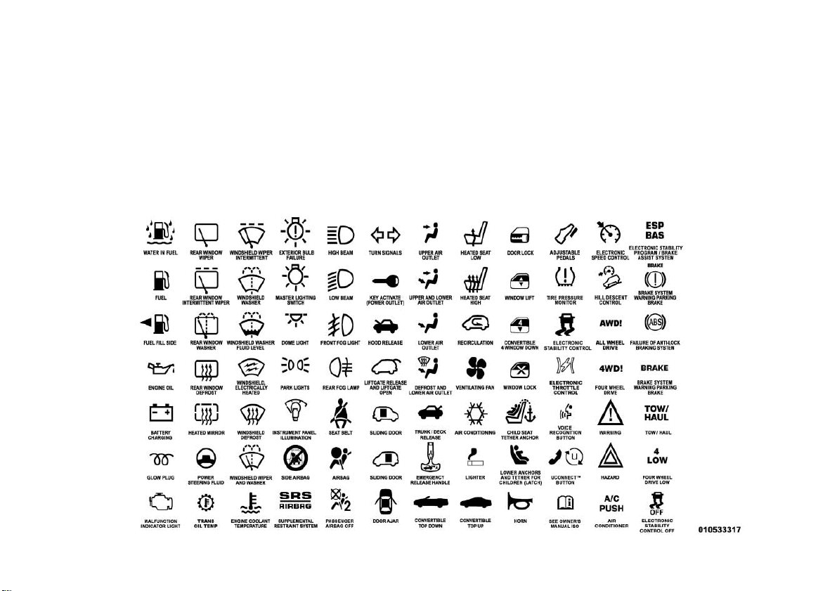
Consult the following table for a description of the symbols that may be
used on your vehicle or throughout
this Owner's Manual:
6
Page 13
WARNINGS AND
CAUTIONS
This Owners Manual contains WARNINGS against operating procedures that
could result in a collision or bodily injury. It also contains CAUTIONS
against procedures that could result in
damage to your vehicle. If you do not
read this entire Owners Manual, you
may miss important information. Observe all Warnings and Cautions.
VEHICLE
IDENTIFICATION
NUMBER
Vehicle Identification Number
VEHICLE
MODIFICATIONS/
ALTERATIONS
WARNING!
Any modifications or alterations to
this vehicle could seriously affect its
roadworthiness and safety and may
lead to a collision resulting in serious
injury or death.
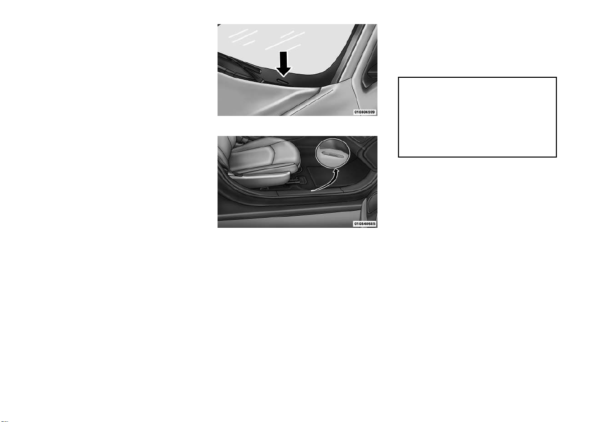
The Vehicle Identification Number
(VIN) is on the left front corner of the
instrument panel and is visible from
outside of the vehicle through the
windshield. This number also appears
stamped on the right front door sill
under the sill moulding and printed
on the Automobile Information Disclosure Label affixed to a window on
your vehicle, the vehicle registration
and title.
Stamped VIN Location
NOTE: It is illegal to remove or
alter the VIN.
7
Page 14

8
Page 15

2
THINGS TO KNOW BEFORE STARTING
YOUR VEHICLE
• A WORD ABOUT YOUR KEYS . . . . . . . . . . . . . . . .12
• IGNITION KEY REMOVAL . . . . . . . . . . . . . . . .12
• KEY-IN-IGNITION REMINDER . . . . . . . . . . . . .13
• LOCKING THE DOORS WITH THE KEY . . . . . .13
• SENTRY KEY® . . . . . . . . . . . . . . . . . . . . . . . . . . .13
• REPLACEMENT KEYS . . . . . . . . . . . . . . . . . . .14
• CUSTOMER KEY PROGRAMMING . . . . . . . . . .14
• GENERAL INFORMATION . . . . . . . . . . . . . . . . .14
• VEHICLE SECURITY ALARM . . . . . . . . . . . . . . . .15
• REARMING OF THE SYSTEM . . . . . . . . . . . . . .15
• TO ARM THE SYSTEM. . . . . . . . . . . . . . . . . . . .15
• TO DISARM THE SYSTEM. . . . . . . . . . . . . . . . .15
• SECURITY MANUAL OVERRIDE . . . . . . . . . . . .16
• ILLUMINATED ENTRY . . . . . . . . . . . . . . . . . . . . .16
• REMOTE KEYLESS ENTRY (RKE) . . . . . . . . . . . .16
• TO UNLOCK THE DOORS . . . . . . . . . . . . . . . . .17
• TO LOCK THE DOORS. . . . . . . . . . . . . . . . . . . .17
• TO UNLATCH THE TRUNK . . . . . . . . . . . . . . . .17
• FLASH LIGHTS WITH LOCK . . . . . . . . . . . . . . .17
9
Page 16

• PROGRAMMING ADDITIONAL
TRANSMITTERS . . . . . . . . . . . . . . . . . . . . . . . .17
• GENERAL INFORMATION . . . . . . . . . . . . . . . . .17
• BATTERY REPLACEMENT . . . . . . . . . . . . . . . .18
• DOOR LOCKS . . . . . . . . . . . . . . . . . . . . . . . . . . . .18
• MANUAL DOOR LOCKS . . . . . . . . . . . . . . . . . . .18
• POWER DOOR LOCKS . . . . . . . . . . . . . . . . . . .19
• WINDOWS . . . . . . . . . . . . . . . . . . . . . . . . . . . . . .19
• POWER WINDOWS . . . . . . . . . . . . . . . . . . . . . .19
• WIND BUFFETING . . . . . . . . . . . . . . . . . . . . . .21
• TRUNK LOCK AND RELEASE . . . . . . . . . . . . . . . .21
• TRUNK SAFETY WARNING . . . . . . . . . . . . . . . . . .22
• TRUNK INTERNAL EMERGENCY RELEASE . . .22
• OCCUPANT RESTRAINTS . . . . . . . . . . . . . . . . . . .22
• LAP/SHOULDER BELTS . . . . . . . . . . . . . . . . . .24
• LAP/SHOULDER BELT UNTWISTING
PROCEDURE . . . . . . . . . . . . . . . . . . . . . . . . . . .26
• SEAT BELTS IN PASSENGER SEATING
POSITIONS . . . . . . . . . . . . . . . . . . . . . . . . . . . .27
• AUTOMATIC LOCKING RETRACTOR
MODE (ALR) . . . . . . . . . . . . . . . . . . . . . . . . . . .27
• ENERGY MANAGEMENT FEATURE. . . . . . . . . .28
• SEAT BELT PRETENSIONERS . . . . . . . . . . . . .28
• SUPPLEMENTAL ACTIVE HEAD
RESTRAINTS (AHR). . . . . . . . . . . . . . . . . . . . . .28
• ENHANCED SEAT BELT USE REMINDER
SYSTEM (BeltAlert®) . . . . . . . . . . . . . . . . . . . .30
• SEAT BELTS AND PREGNANT WOMEN . . . . . .31
10
Page 17

• SUPPLEMENTAL RESTRAINT SYSTEM
(SRS) — AIR BAGS . . . . . . . . . . . . . . . . . . . . . .31
• Air Bag Deployment Sensors And Controls . . . . .34
• Event Data Recorder (EDR) . . . . . . . . . . . . . . . .38
• CHILD RESTRAINTS . . . . . . . . . . . . . . . . . . . .39
• ENGINE BREAK-IN RECOMMENDATIONS . . . . . .47
• SAFETY TIPS . . . . . . . . . . . . . . . . . . . . . . . . . . . .47
• Transporting Passengers . . . . . . . . . . . . . . . . . .47
• Exhaust Gas . . . . . . . . . . . . . . . . . . . . . . . . . . .48
• Safety Checks You Should Make Inside The
Vehicle . . . . . . . . . . . . . . . . . . . . . . . . . . . . . . .48
• Periodic Safety Checks You Should Make
Outside The Vehicle . . . . . . . . . . . . . . . . . . . . . .50
11
Page 18
A WORD ABOUT YOUR
KEYS
The authorized dealer that sold you
your vehicle has the key code numbers
for your vehicle locks. These numbers
can be used to order duplicate keys
from your authorized dealer. Ask your
authorized dealer for these numbers
and keep them in a safe place.
You can insert the double-sided keys
into the locks with either side up.
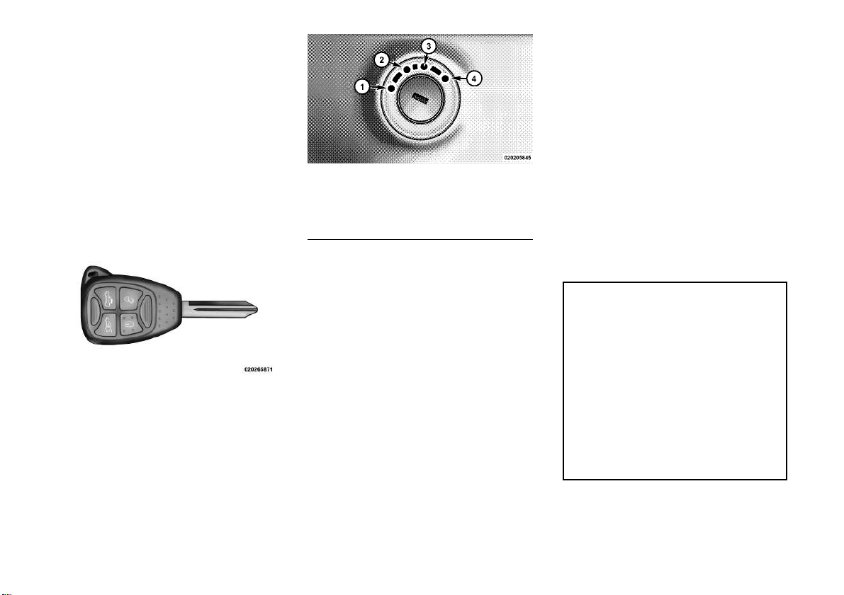
Ignition Switch Positions
1 — LOCK 3 — ON/RUN
2 — ACC
(ACCESSORY)
NOTE:
4 — START
•
The power window switches, radio,
hands-free system , and power outlets will remain active for up to
10 minutes after the ignition switch
is turned to the LOCK position.
Opening either front door will
cancel this feature. The time for
this feature is programmable. Refer to “Electronic Vehicle Information Center (EVIC)/Personal Settings (Customer-Programmable
Features)” in “Understanding Your
Instrument Panel” for further information.
Vehicle Key
IGNITION KEY REMOVAL
Automatic Transaxle
Place the shift lever in PARK. Turn
the ignition switch to the ACC position, push the key and cylinder inward, rotate the key to the LOCK
position, and remove the key.
12
• If you try to remove the key before you place the shift lever in
PARK, the key may become
trapped temporarily in the ignition switch lock cylinder. If this
occurs, rotate the key to the right
slightly, then remove the key as
described. If a malfunction occurs, the system will trap the key
in the ignition switch lock cylinder to warn you that this safety
feature is inoperable. The engine can be started and stopped,
but the key cannot be removed
until you obtain service.
WARNING!
• Before exiting a vehicle, always
apply the parking brake, shift the
transmission into PARK, and
push ignition button to place ignition in OFF position. When
leaving the vehicle, always lock
your vehicle.
• Never leave children alone in a
vehicle, or with access to an unlocked vehicle.
(Continued)
Page 19

WARNING! (Continued)
• Allowing children to be in a vehicle unattended is dangerous for
a number of reasons. A child or
others could be seriously or fatally injured. Children should be
warned not to touch the parking
brake, brake pedal or the shift
lever.
• Do not leave the Key Fob in or
near the vehicle, or in a location
accessible to children, and do not
leave the ignition in the ACC or
ON/RUN position. A child could
operate power windows, other
controls, or move the vehicle.
• Do not leave children or animals
inside parked vehicles in hot
weather. Interior heat build-up
may cause serious injury or
death.
CAUTION!
An unlocked car is an invitation to
thieves. Always remove key from
the ignition and lock all doors when
leaving the vehicle unattended.
KEY-IN-IGNITION
REMINDER
Opening the driver's door when the
key is in the ignition sounds a signal to
remind you to remove the key.
NOTE:
• The Key-In-Ignition reminder
only sounds when the ignition
key is placed in the LOCK or
ACC position.
• With either/both front doors
open and a key in the ignition,
the power door lock buttons on
the interior trim panel are disabled. This is an attempt to limit
locking the keys in the vehicle.
LOCKING THE DOORS
WITH THE KEY
There is only one external door lock
cylinder which is located in the driver's door.
You can insert the key with either side
up. To lock the door, turn the key
clockwise. To unlock the door, turn
the key counterclockwise. For door
lock lubrication, see “Maintenance
Procedures” in “MaintainingYour Vehicle” of this manual.
SENTRY KEY®
The Sentry Key® Immobilizer System
prevents unauthorized vehicle operation by disabling the engine. The system does not need to be armed or
activated. Operation is automatic, regardless of whether the vehicle is
locked or unlocked.
The system uses ignition keys which
have an embedded electronic chip
(transponder) to prevent unauthorized vehicle operation. Therefore,
only keys that are programmed to the
vehicle can be used to start and operate the vehicle. The system will shut
the engine off in two seconds if someone uses an invalid key to start the
engine.
NOTE: A key which has not been
programmed is also considered an
invalid key, even if it is cut to fit the
ignition switch lock cylinder for
that vehicle.
13
Page 20

During normal operation, after turning on the ignition switch, the Vehicle
Security Light will turn on for three
seconds for a bulb check. If the light
remains on after the bulb check, it
indicates that there is a problem with
the electronics. In addition, if the light
begins to flash after the bulb check, it
indicates that someone used an invalid key to start the engine. Either of
these conditions will result in the engine being shut off after two seconds.
If the Vehicle Security Light turns on
during normal vehicle operation (vehicle running for longer than 10 seconds), it indicates that there is a fault
in the electronics. Should this occur,
have the vehicle serviced as soon as
possible by an authorized dealer.
CAUTION!
The Sentry Key® Immobilizer system is not compatible with some
after-market remote starting systems. Use of these systems may result in vehicle starting problems
and loss of security protection.
All of the keys provided with your new
vehicle have been programmed to the
vehicle electronics.
REPLACEMENT KEYS
NOTE: Only keys that have been
programmed to the vehicle electronics can be used to start the
vehicle. Once a Sentry Key® has
been programmed to a vehicle, it
cannot be programmed to any
other vehicle.
CAUTION!
Always remove Sentry Keys from
the vehicle and lock all doors when
leaving the vehicle unattended.
At the time of purchase, the original
owner is provided with a four-digit
Personal Identification Number (PIN).
Keep the PIN in a secure location. This
number is required for authorized
dealer replacement of keys. Duplication of keys consists of programming a
blank key to the vehicle electronics. A
blank key is one which has never been
programmed. See your authorized
dealer if you require replacement or
additional keys for your vehicle.
NOTE: When having the Sentry
Key® Immobilizer System serviced, bring all vehicle keys with
you to the authorized dealer.
CUSTOMER KEY
PROGRAMMING
See your authorized dealer if you require replacement or additional keys
for your vehicle.
GENERAL INFORMATION
The Sentry Key® operates on a carrier frequency of 433.92 MHz.
Operation is subject to the following
conditions:
• This device may not cause harmful
interference.
• This device must accept any interference that may be received, including interference that may cause
undesired operation.
14
Page 21

VEHICLE SECURITY
ALARM
The Vehicle Security Alarm monitors
the doors, and trunk for unauthorized
entry and ignition switch for unauthorized operation.
While the Vehicle Security Alarm is
armed, interior switches for door
locks and decklid release are disabled.
If something triggers the alarm, the
Vehicle Security Alarm will sound the
horn intermittently, flash the headlights, the park lights, and the taillights, and flash the Vehicle Security
Light in the cluster.
REARMING OF THE
SYSTEM
If something triggers the alarm, and
no action is taken to disarm it, the
Vehicle Security Alarm will turn off
the horn after three minutes, turn off
all of the visual signals after 15 minutes, and then the Vehicle Security
Alarm will rearm itself.
TO ARM THE SYSTEM
1. Remove the keys from the ignition
switch and exit the vehicle.
2. Lock the doors by pressing the
power door lock switch or the LOCK
button on the Remote Keyless Entry
(RKE) transmitter.
NOTE: The Vehicle Security
Alarm will not arm if you lock the
doors with the manual door lock
plungers.
3. Close all doors. The Vehicle Security Light in the instrument cluster
will flash rapidly for 16 seconds. This
shows that the Vehicle Security Alarm
is arming. After 16 seconds, the Vehicle Security Light will flash slowly.
This shows that the Vehicle Security
Alarm is fully armed.
NOTE:
• During the 16–second arming
period, if a door is opened or the
ignition switch is turned to ON/
RUN, the Vehicle Security Alarm
will automatically disarm.
•
While the Vehicle Security Alarm
is armed, interior switches for
door locks and decklid release are
disabled.
TO DISARM THE SYSTEM
Either press the UNLOCK button on
the RKE transmitter or insert a valid
Sentry Key® into the ignition switch
lock cylinder and turn the key to the
ON/RUN or START position.
NOTE:
• The driver's door key cylinder
and the trunk button on the RKE
transmitter cannot arm or disarm the Vehicle Security Alarm.
•
The Vehicle Security Alarm remains armed during trunk entry.
Pressing the trunk button will not
disarm the Vehicle Security
Alarm. If someone enters the vehicle through the trunk and opens
any door, the alarm will sound.
•
When the Vehicle Security Alarm
is armed, the interior power door
lock switches will not unlock the
doors.
15
Page 22
The Vehicle Security Alarm is designed to protect your vehicle; however, you can create conditions where
the Vehicle Security Alarm will give
you a false alarm. If one of the previously described arming sequences has
occurred, the Vehicle Security Alarm
will arm regardless of whether you are
in the vehicle or not. If you remain in
the vehicle and open a door, the alarm
will sound. If this occurs, disarm the
Vehicle Security Alarm.
If the Vehicle Security Alarm is armed
and the battery becomes disconnected, the Vehicle Security Alarm
will remain armed when the battery is
reconnected. The exterior lights will
flash, and the horn will sound. If this
occurs, disarm the Vehicle Security
Alarm.
SECURITY MANUAL
OVERRIDE
The Vehicle Security Alarm will not
arm if you lock the doors using the
manual door lock plunger.
ILLUMINATED ENTRY
The courtesy lights will turn on when
you press the unlock button on the
Remote Keyless Entry (RKE) transmitter or open any door.
The interior lights will fade to off after
approximately 30 seconds or they will
immediately fade to off once the ignition switch is turned to ON/RUN from
the OFF position.
NOTE:
• The front courtesy overhead
console and door courtesy lights
will turn on if the dimmer control is in the "Dome ON" position
(extreme top position).
•
The Illuminated Entry system
will not operate if the dimmer
control is in the “Dome defeat”
position (extreme bottom position).
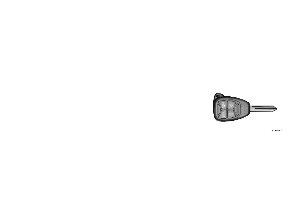
REMOTE KEYLESS
ENTRY (RKE)
This system allows you to lock or
unlock the doors, open the trunk and
open the convertible top from distances up to approximately 10 m
using a hand-held Remote Keyless
Entry (RKE) transmitter. The RKE
transmitter does not need to be
pointed at the vehicle to activate the
system.
Vehicle Key
NOTE: The line of transmission
must not be blocked with metal
objects.
16
Page 23

TO UNLOCK THE DOORS
TO UNLATCH THE TRUNK
GENERAL INFORMATION
Press and release the UNLOCK button on the RKE transmitter once to
unlock the driver's door or twice to
unlock all doors. The turn signal
lights will flash to acknowledge the
unlock signal. The illuminated entry
system will also turn on.
Remote Key Unlock — Driver
Door/All Doors First
This feature lets you program the system to unlock either the driver's door
or all doors on the first press of the
UNLOCK button on the RKE transmitter.
Refer to “Electronic Vehicle Information Center (EVIC)/Personal Settings
(Customer-Programmable Features)”
in “Understanding Your Instrument
Panel” for further information.
TO LOCK THE DOORS
Press and release the LOCK button on
the transmitter to lock all doors.
Press the trunk button on the transmitter two times to unlatch the trunk.
FLASH LIGHTS WITH
LOCK
The feature will cause the turn signal
lights to flash when the doors are
locked or unlocked with the RKE
transmitter. This feature can be
turned on or turned off.
Refer to “Electronic Vehicle Information Center (EVIC)/Personal Settings
(Customer-Programmable Features)”
in “Understanding Your Instrument
Panel” for further information.
PROGRAMMING
ADDITIONAL
TRANSMITTERS
Refer to Sentry Key® “Customer Key
Programming.”
If you do not have a programmed
RKE transmitter, contact your authorized dealer for details.
Transmitter and receivers operate on
a carrier frequency of 433.92 MHz.
Operation is subject to the following
conditions:
1. This device may not cause harmful
interference.
2. This device must accept any interference that may be received including interference that may cause undesired operation.
NOTE: Changes or modifications
not expressly approved by the
party responsible for compliance
could void the user's authority to
operate the equipment.
If your RKE transmitter fails to operate from a normal distance, check for
these two conditions:
1.
Weak battery in transmitter. The ex-
pected life of a battery is five years.
2. Closeness to a radio transmitter
such as a radio station tower, airport
transmitter, military base, and some
mobile or CB radios.
17
Page 24
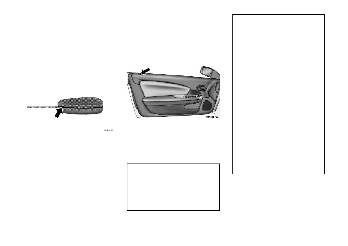
BATTERY REPLACEMENT
The recommended replacement battery is CR2032.
1. With the RKE transmitter buttons
facing down, use a flat blade to pry
the two halves of the RKE transmitter
apart. Make sure not to damage the
seal during removal.
Separating RKE Transmitter Halves
2. Remove and replace the battery.
Avoid touching the new battery with
your fingers. Skin oils may cause battery deterioration. If you touch a battery, clean it with rubbing alcohol.
3. To assemble the RKE transmitter
case, snap the two halves together.
DOOR LOCKS
MANUAL DOOR LOCKS
To lock each door, push the door lock
knob on each door trim panel downward. To unlock each door, pull the
inside door handle.
Manual Lock Knob
If the door lock knob is down when
you shut the door, the door will lock.
Make sure the keys are not inside the
vehicle before closing the door.
WARNING!
• For personal security and safety
in the event of an collision, lock
the vehicle doors as you drive as
well as when you park and leave
the vehicle.
WARNING! (Continued)
• When leaving the vehicle, always
remove the key fob from the ignition and lock your vehicle.
• Never leave children alone in a
vehicle, or with access to an unlocked vehicle.
• Allowing children to be in a vehicle unattended is dangerous for
a number of reasons. A child or
others could be seriously or fatally injured. Children should be
warned not to touch the parking
brake, brake pedal or the shift
lever.
• Do not leave the key fob in or near
the vehicle, or in a location accessible to children, and do not leave
the ignition in the ACC or ON/
RUN position. A child could operate power windows, other controls, or move the vehicle.
18
(Continued)
Page 25
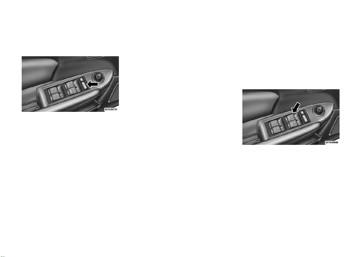
POWER DOOR LOCKS
A door lock switch is located on the
driver and passenger door trim panel.
Press this switch to lock or unlock the
doors.
Auto Unlock On Exit
The doors will unlock automatically
on vehicles with power door locks if:
1. The Automatic Unlock Doors On
Exit feature is enabled.
2. The transaxle was in gear and the
vehicle speed returned to 0 km/h.
3. The transaxle is in NEUTRAL or
PARK.
4. The driver door is opened.
NOTE: Use the Automatic Unlock
Doors On Exit feature in accordance with local laws.
WINDOWS
POWER WINDOWS
The window controls on the driver's
door trim panel operate the door windows and the rear quarter windows.
Power Door Lock Switch
Automatic Door Locks
The auto door lock feature default
condition is disabled. When enabled,
the door locks will lock automatically
when the vehicle's speed exceeds
24 km/h. The auto door lock feature
can be enabled or disabled by your
authorized dealer. Please see your authorized dealer for service.
5. The doors were not previously unlocked.
6. The vehicle speed is 0 km/h.
Auto Unlock Door On Exit
Programming
The Automatic Unlock Doors On Exit
feature can be enabled or disabled.
Refer to “Electronic Vehicle Information Center (EVIC)/Personal Settings
(Customer-Programmable Features)”
in “Understanding Your Instrument
Panel” for further information.
Power Window Switches
There is a single window control on
the passenger's door trim panel,
which operates the passenger door
window. The window controls will operate when the ignition switch is
turned to the ON/RUN or ACC position, and when the accessory delay
feature is active.
19
Page 26

NOTE:
• If a fluttering noise is heard from
the rear seat belts while driving
with the windows down, safely
bring the vehicle to a stop and
buckle the rear seat belts over
the empty seats. This will keep
tension on the seat belts and remove the fluttering condition.
WARNING!
Never leave children in a vehicle,
with the keys in the ignition switch.
Occupants, particularly unattended
children, can become entrapped by
the windows while operating the
power window switches. Such entrapment may result in serious injury or death.
Smart Glass Feature
The door window will lower slightly if
the window is fully up when opening
the door. The window will return to its
full up position after closing the door.
This action allows the door to open
without resistance and prevents window and top seal damage.
Auto Window Down
The front window controls on the
driver and passenger door trim panels
have an Auto-Down feature. These
switches are labeled AUTO to indicate
this capability. Push the window
switch past the first detent, release,
and the window will go down automatically.
To open the window part way, push
the window switch to the first detent
and release it when you want the window to stop.
To cancel the Auto-Down movement,
operate the switch either in the up or
down direction and release the switch.
The power window switches will remain
active for up to 10 minutes after the
ignition switch is turned to the LOCK
position. Opening either door will cancel this feature. The time for this feature
is programmable. Refer to “Electronic
Vehicle Information Center (EVIC)/
Personal Settings (Customer-Programmable Features)” in “Understanding
Your Instrument Panel” for further information.
Reset Window Smart Glass
Feature for Opening/Closing the
Door
If the vehicle battery goes dead, the
window Smart Glass Feature for
opening and closing the door will be
disabled. To reactivate the window
Smart Glass Feature, perform the following steps after vehicle power is
restored.
1. Lower all four windows to the full
open position.
2. Press and hold the Power Top
Switch in the Close direction. Once
the Power Top becomes fully closed,
all four windows will start closing.
3. Continue to hold the Power Top
Switch an additional two seconds
after the windows are fully closed.
4. Push all the window switches
down firmly to open the windows
completely and continue to hold the
switch down for an additional two
seconds after the window is fully
open.
20
Page 27
Window Lockout Switch
The window lockout switch on the
driver's door trim panel allows you to
disable the window control on the passenger door. To disable the window
control on the passenger door, press
and release the window LOCK button
(setting it in the down position). To
enable the window control, press and
release the window LOCK button
again (setting it in the up position).
Window Lockout Switch
WIND BUFFETING
Wind buffeting can be described as
the perception of pressure on the ears
or a helicopter-type sound in the ears.
Your vehicle may exhibit wind buffeting with one window down in certain
open or partially open positions. This
is a normal occurrence and can be
minimized. If the buffeting occurs
with one window open, then open
both windows together to minimize
the buffeting.
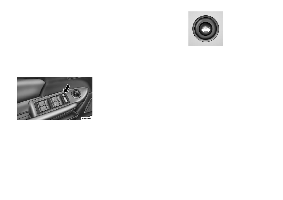
TRUNK LOCK AND
RELEASE
To unlatch the trunk lid from inside
the vehicle, press and release the
TRUNK RELEASE Button located on
the instrument panel to the left of the
steering wheel.
NOTE:
• The convertible top must be either closed and latched or open
and latched to release the trunk.
• The transmission must be in
PARK before the button will operate.
The trunk release
button on the dash
will be disabled if
the vehicle is
locked by pressing
the power door
Trunk Release
Button
mote Keyless Entry (RKE) transmitter. The trunk release button will be
enabled when the vehicle is unlocked
by the RKE or if the key is inserted
into the ignition and turned to ON/
RUN or START.
NOTE: This provides a locked
area in the vehicle even if the convertible top is open.
To unlatch the trunk lid from outside
the vehicle, press and release the
TRUNK RELEASE button on the
RKE transmitter two times.
The words “Trunk Ajar” will display
in the Electronic Vehicle Information
Center (EVIC).
lock switch or by
pressing the LOCK
button on the Re-
21
Page 28
TRUNK SAFETY
WARNING
WARNING!
Do not allow children to have access to the trunk, either by climbing
into the trunk from outside, or
through the inside of the vehicle.
Always close the trunk lid when
your vehicle is unattended. Once in
the trunk, young children may not
be able to escape, even if they entered through the rear seat. If
trapped in the trunk, children can
die from suffocation or heat stroke.
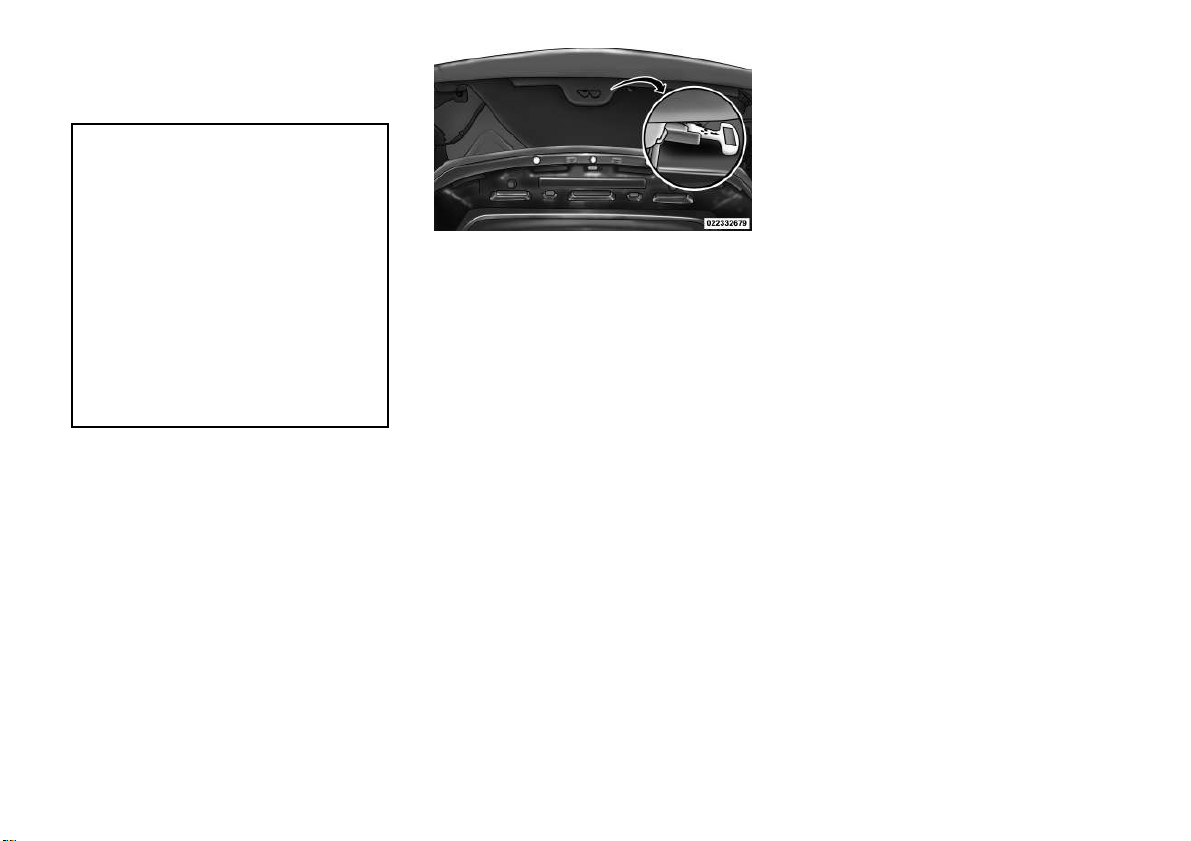
TRUNK INTERNAL
EMERGENCY RELEASE
As a security measure, a Trunk Internal Emergency Release lever is built
into the trunk latching mechanism. In
the event of an individual being
locked inside the trunk, the trunk can
be simply opened by pulling on the
glow-in-the-dark handle attached to
the trunk latching mechanism.
Trunk Internal Emergency Release
OCCUPANT RESTRAINTS
Some of the most important safety
features in your vehicle are the restraint systems:
• Three-point lap and shoulder belts
for all seating positions
• Advanced Front Air Bags for driver
and front passenger
• Supplemental Active Head Restraints (AHR) located on top of the
front seats (integrated into the head
restraint)
• Supplemental Seat-Mounted Side
Air Bags (SAB)
• An energy-absorbing steering column and steering wheel
• Knee bolsters/blockers for front
seat occupants
• Front seat belts incorporate pretensioners that may enhance occupant
protection by managing occupant
energy during an impact event
• Rear passenger seat belts include
Automatic Locking Retractors
(ALRs), which lock the seat belt
webbing into position by extending
the belt all the way out and then
adjusting the belt to the desired
length to restrain a child seat or
secure a large item in a seat.
Please pay close attention to the information in this section. It tells you how
to use your restraint system properly,
to keep you and your passengers as
safe as possible.
If you will be carrying children too
small for adult-sized seat belts, the
seat belts or the ISOFIX feature also
can be used to hold infant and child
restraint systems. For more information, refer to ISOFIX — Child Seat
Anchorage System.
22
Page 29

NOTE: The Advanced Front Air
Bags have a multistage inflator design. This allows the air bag to
have different rates of inflation
based on several factors, including
the severity and type of collision.
Here are some simple steps you can
take to minimize the risk of harm
from a deploying air bag:
1. Children 12 years old and un-
der should always ride buckled up
in a rear seat.
WARNING!
Infants in rear facing child restraints should never ride in the
front seat of a vehicle with a passenger Advanced Front Air Bag.
An air bag deployment can cause
severe injury or death to infants in
that position.
Children that are not big enough to
wear the vehicle seat belt properly
(see section on Child Restraints)
should be secured in the rear seat in
child restraints or belt-positioning
booster seats. Older children who do
not use child restraints or beltpositioning booster seats should ride
properly buckled up in the rear seat.
Never allow children to slide the
shoulder belt behind them or under
their arm.
You should read the instructions provided with your child restraint to make
sure that you are using it properly.
2. All occupants should always
wear their lap and shoulder belts
properly.
3. The driver and front passenger
seats should be moved back as far
as practical to allow the Advanced
Front Air Bags room to inflate.
4. Do not lean against the door or
window. If your vehicle has side
air bags, and deployment occurs,
the side air bags will inflate forcefully into the space between you
and the door.
5.
If the air bag system in this vehicle needs to be modified to accommodate a disabled person,
contact the Customer Center.
WARNING!
Infants in rear facing child restraints should never ride in the
front seat of a vehicle with a passenger Advanced Front Air Bag.
An air bag deployment can cause
severe injury or death to infants in
that position.
Buckle up even though you are an
excellent driver, even on short trips.
Someone on the road may be a poor
driver and cause a collision that includes you. This can happen far away
from home or on your own street.
23
Page 30

WARNING!
• Relying on the air bags alone
could lead to more severe injuries
in a collision. The air bags work
with your seat belt to restrain you
properly. In some collisions, the
air bags won't deploy at all. Always wear your seat belts even
though you have air bags.
• Being too close to the steering
wheel or instrument panel during
Advanced Front Air Bag deployment could cause serious injury,
including death. Air Bags need
room to inflate. Sit back, comfortably extending your arms to
reach the steering wheel or instrument panel.
• Seat-Mounted Side Air Bags
(SAB) need room to inflate. Do
not lean against the door or window. Sit upright in the center of
the seat.
• In a collision, you and your passengers can suffer much greater
injuries if you are not properly
buckled up. You can strike the
(Continued)
WARNING! (Continued)
interior of your vehicle or other
passengers, or you can be thrown
out of the vehicle. Always be sure
you and others in your vehicle are
buckled up properly.
Research has shown that seat belts
save lives, and they can reduce the
seriousness of injuries in a collision.
Some of the worst injuries happen
when people are thrown from the vehicle. Seat belts reduce the possibility
of ejection and the risk of injury
caused by striking the inside of the
vehicle. Everyone in a motor vehicle
should be belted at all times.
LAP/SHOULDER BELTS
All seating positions in your vehicle
are equipped with lap/shoulder belts.
The belt webbing retractor is designed to lock during very sudden
stops or collisions. This feature allows
the shoulder part of the belt to move
freely with you under normal conditions. However, in a collision, the belt
will lock and reduce the risk of you
striking the inside of the vehicle or
being thrown out.
WARNING!
• Be sure everyone in your vehicle is
in a seat and using a seat belt
properly.
• It is dangerous to ride in a cargo
area, inside or outside of a vehicle. In a collision, people riding
in these areas are more likely to
be seriously injured or killed.
•
Do not allow people to ride in any
area of your vehicle that is not
equipped with seats and seat belts.
• Wearing a seat belt incorrectly is
dangerous. Seat belts are designed to go around the large
bones of your body. These are the
strongest parts of your body and
can take the forces of a collision
the best.
• Wearing your belt in the wrong
place could make your injuries in
a collision much worse. You
might suffer internal injuries, or
you could even slide out of part of
the belt. Follow these instructions
to wear your seat belt safely and
to keep your passengers safe, too.
(Continued)
24
Page 31

WARNING! (Continued)
• Two people should never be
belted into a single seat belt.
People belted together can crash
into one another in a collision,
hurting one another badly. Never
use a lap/shoulder belt or a lap
belt for more than one person, no
matter what their size.
Lap/Shoulder Belt Operating
Instructions
1.
Enter the vehicle and close the door.
Sit back and adjust the front seat.
2. The seat belt latch plate is on the
outboard side of the front seat, next to
your arm. Grasp the latch plate and
pull out the belt. Slide the latch plate
up the webbing as far as necessary to
allow the belt to go around your lap.
Pulling Out The Latch Plate
3. When the belt is long enough to fit,
insert the latch plate into the buckle
until you hear a “click.”
Positioning The Lap Belt
WARNING!
• A belt buckled into the wrong
buckle will not protect you properly. The lap portion could ride
too high on your body, possibly
WARNING! (Continued)
causing internal injuries. Always
buckle your belt into the buckle
nearest you.
• A belt that is too loose will not
protect you properly. In a sudden
stop you could move too far forward, increasing the possibility of
injury. Wear your seat belt snugly.
• A belt that is worn under your
arm is dangerous. Your body
could strike the inside surfaces of
the vehicle in a collision, increasing head and neck injury. A belt
worn under the arm can cause
internal injuries. Ribs aren't as
strong as shoulder bones. Wear
the belt over your shoulder so that
your strongest bones will take the
force in a collision.
A shoulder belt placed behind you
•
will not protect you from injury
during a collision. You are more
likely to hit your head in a collision if you do not wear your shoulder belt. The lap and shoulder belt
are meant to be used together.
(Continued)
25
Page 32

4. Position the lap belt across your
thighs, below your abdomen. To remove slack in the lap belt portion, pull
up on the shoulder belt. To loosen the
lap belt if it is too tight, lift up on the
shoulder belt and pull on the lap belt.
A snug belt reduces the risk of sliding
under the belt in a collision.
Inserting Latch Plate Into Buckle
WARNING!
•
A lap belt worn too high can increase the risk of injury in a collision. The belt forces won't be at
the strong hip and pelvic bones,
but across your abdomen. Always
wear the lap part of your seat belt
as low as possible and keep it snug.
WARNING! (Continued)
• A twisted belt may not protect
you properly. In a collision, it
could even cut into you. Be sure
the belt is straight. If you can't
straighten a belt in your vehicle,
take it to your authorized dealer
immediately and have it fixed.
5. Position the shoulder belt on your
chest so that it is comfortable and not
resting on your neck. The retractor
will withdraw any slack in the belt.
6. To release the belt, push the red
button on the buckle. The belt will
automatically retract to its stowed position. If necessary, slide the latch
plate down the webbing to allow the
belt to retract fully.
LAP/SHOULDER BELT
UNTWISTING PROCEDURE
Use the following procedure to untwist a twisted lap/shoulder belt.
1. Position the latch plate as close as
possible to the anchor point.
2. At about 15 to 30 cm above the
latch plate, grasp and twist the belt
webbing 180° to create a fold that
begins immediately above the latch
plate.
3. Slide the latch plate upward over
the folded webbing. The folded webbing must enter the slot at the top of
the latch plate.
4. Continue to slide the latch plate up
until it clears the folded webbing.
26
(Continued)
Page 33

SEAT BELTS IN
PASSENGER SEATING
POSITIONS
The seat belts in the rear passenger
seating positions are equipped with
Automatic Locking Retractors (ALR)
which are used to secure a child restraint system. For additional information, refer to “Installing Child Restraints Using The Vehicle Seat Belt”
under the “Child Restraints” section.
The chart below defines the type of
feature for each seating position.
Driver Cen-
ter
First
Row
Second
Row
• N/A — Not Applicable
•
ALR — Automatic Locking Retractor
N/A N/A N/A
ALR N/A ALR
Passenger
If the passenger seating position is
equipped with an ALR and is being
used for normal usage:
Only pull the belt webbing out far
enough to comfortably wrap around
the occupant's mid-section so as to
not activate the ALR. If the ALR is
activated, you will hear a ratcheting
sound as the belt retracts. Allow the
webbing to retract completely in this
case and then carefully pull out only
the amount of webbing necessary to
comfortably wrap around the occupant's mid-section. Slide the latch
plate into the buckle until you hear a
"click."
AUTOMATIC LOCKING
RETRACTOR MODE (ALR)
In this mode, the shoulder belt is automatically pre-locked. The belt will
still retract to remove any slack in the
shoulder belt. The Automatic Locking
Mode is available on rear passengerseating positions with a combination
lap/shoulder belt. Use the Automatic
Locking Mode anytime a child safety
seat is installed in a seating position
that has a belt with this feature. Children 12 years old and under should
always be properly restrained in the
rear seat.
How To Engage The Automatic
Locking Mode
1. Buckle the combination lap and
shoulder belt.
2. Grasp the shoulder portion and
pull downward until the entire belt is
extracted.
3. Allow the belt to retract. As the
belt retracts, you will hear a clicking
sound. This indicates the safety belt is
now in the Automatic Locking Mode.
How To Disengage The Automatic
Locking Mode
Unbuckle the combination lap/
shoulder belt and allow it to retract
completely to disengage the Automatic
Locking Mode and activate the vehicle
sensitive (emergency) locking mode.
27
Page 34

WARNING!
• The belt and retractor assembly
must be replaced if the seat belt
assembly Automatic Locking Retractor (ALR) feature or any
other seat belt function is not
working properly when checked
according to the procedures in the
Service Manual.
• Failure to replace the belt and
retractor assembly could increase
the risk of injury in collisions.
ENERGY MANAGEMENT
FEATURE
This vehicle has a safety belt system
with an Energy Management feature
in the front seating positions to help
further reduce the risk of injury in the
event of a head-on collision. This
safety belt system has a retractor assembly that is designed to release
webbing in a controlled manner. This
feature is designed to help reduce the
belt force acting on the occupant’s
chest.
SEAT BELT
PRETENSIONERS
The seat belts for both front seating
positions are equipped with pretensioning devices that are designed to
remove slack from the seat belt in the
event of a collision. These devices may
improve the performance of the seat
belt by assuring that the belt is tight
about the occupant early in a collision. Pretensioners work for all size
occupants, including those in child
restraints.
NOTE: These devices are not a
substitute for proper seat belt
placement by the occupant. The
seat belt still must be worn snugly
and positioned properly.
The pretensioners are triggered by the
Occupant Restraint Controller
(ORC). Like the air bags, the pretensioners are single use items. A deployed pretensioner or a deployed air
bag must be replaced immediately.
SUPPLEMENTAL ACTIVE
HEAD RESTRAINTS (AHR)
These head restraints are passive, deployable components, and vehicles
with this equipment cannot be readily
identified by any markings, only
through visual inspection of the head
restraint. The head restraint will be
split in two halves, with the front half
being soft foam and trim, the back
half being decorative plastic.
How The Active Head Restraints
(AHR) Work
The Occupant Restraint Controller
(ORC) determines whether the severity, or type of rear impact will require
the Active Head Restraints (AHR) to
deploy. If a rear impact requires deployment, both the driver and front
passenger seat AHRs will be deployed.
When AHRs deploy during a rear impact, the front half of the head restraint extends forward to minimize
the gap between the back of the occupant’s head and the AHR. This system
is designed to help prevent or reduce
28
Page 35

the extent of injuries to the driver and
front passenger in certain types of
rear impacts.
NOTE: The Active Head Restraints (AHR) may or may not deploy in the event of a front or side
impact. However if during a front
impact, a secondary rear impact
occurs, the AHR may deploy based
on several factors, including the
severity and type of the impact.
Active Head Restraint (AHR)
Components
1 — Head Restraint
Front Half (Soft
Foam and Trim)
2 — Seatback
3 — Head Restraint
Back Half (Decorative Plastic Rear
Cover)
4 — Head Restraint
Guide Tubes
CAUTION!
All occupants, including the driver,
should not operate a vehicle or sit in
a vehicle's seat until the head restraints are placed in their proper
positions in order to minimize the
risk of neck injury in the event of a
collision.
NOTE: For more information on
properly adjusting and positioning
the head restraint, refer to “Head
Restraints” in “Understanding The
Features Of Your Vehicle”.
NOTE:
• If you have difficulties or problems resetting the Active Head
Restraints, see an authorized
dealer.
• For safety reasons, have the Active Head Restraints checked by
a qualified specialist at an authorized dealer.
Resetting Active Head Restraints
(AHR)
If the Active Head Restraints are triggered in a collision, you must reset the
head restraint on the driver’s and front
passenger seat. You can recognize
when the Active Head Restraint has
been triggered by the fact that they
have moved forward (as shown in step
three of the resetting procedure).
1. Grasp the deployed AHR from the
rear seat.
Hand Positioning Points On AHR
2. Position the hands on the top of
the deployed AHR at a comfortable
position.
29
Page 36

3.
Pull
down then rearward towards the rear of the vehicle then
down to engage the locking mechanism.
1 — Downward Movement
2 — Rearward Movement
3 — Final Downward Movement To
Engage Locking Mechanism
4. The AHR front soft foam and trim
half should lock into the back decorative plastic half.
AHR In Reset Position
NOTE:
• If you have difficulties or problems resetting the Active Head
Restraints, see an authorized
dealer.
• For safety reasons, have the Active Head Restraints checked by
a qualified specialist at an authorized dealer.
ENHANCED SEAT BELT
USE REMINDER SYSTEM
(BeltAlert®)
BeltAlert® is a feature intended to
remind the driver to fasten the seat
belt. The feature is active whenever
the ignition is on. If the driver is unbelted, the Seat Belt Reminder Light
will turn on and remain on until the
seat belt is fastened.
The BeltAlert® warning sequence begins after the vehicle speed is over
8 km/h, by blinking the Seat Belt
Reminder Light and sounding an intermittent chime. Once the sequence
starts, it will continue for the entire
duration or until the respective seatbelt is fastened. After the sequence
completes, the Seat Belt Reminder
Light remains illuminated until the
respective seat belt is fastened. The
driver should instruct all other occupants to fasten their seat belts. If the
driver's seat belt is unbuckled while
traveling at speeds greater than
8 km/h, BeltAlert® will provide both
audio and visual notification.
30
Page 37

BeltAlert® can be enabled or disabled
by your authorized dealer. LANCIA
does not recommend deactivating
BeltAlert®.
NOTE: Although BeltAlert® has
been deactivated, the Seat Belt
Reminder Light will continue to
illuminate while the driver’s seat
belt remains unfastened.
SEAT BELTS AND
PREGNANT WOMEN
We recommend that pregnant women
use the seat belts throughout their
pregnancy. Keeping the mother safe is
the best way to keep the baby safe.
Pregnant women should wear the lap
part of the belt across the thighs and
as snug across the hips as possible.
Keep the belt low so that it does not
come across the abdomen. That way
the strong bones of the hips will take
the force if there is a collision.
SUPPLEMENTAL
RESTRAINT SYSTEM
(SRS) — AIR BAGS
This vehicle has Advanced Front Air
Bags for both the driver and front
passenger as a supplement to the seat
belt restraint systems. The driver's
Advanced Front Air Bag is mounted
in the center of the steering wheel.
The passenger's Advanced Front Air
Bag is mounted in the instrument
panel, above the glove compartment.
The words SRS AIRBAG are embossed on the air bag covers.
Advanced Front Air Bag And Knee
Bolster Locations
1 — Driver And Passenger Advanced
Front Air Bags
2 — Knee Bolster
NOTE: The Driver and Front Passenger Advanced Front Air Bags
are certified to the new regulations
for Advanced Air Bags.
The Advanced Front Air Bags have a
multistage inflator design. This allows
the air bag to have different rates of
inflation that are based on several factors, including the severity and type of
collision.
This vehicle may be equipped with a
driver and/or front passenger seat
belt buckle switch that detects
whether the driver or front passenger
seat belt is fastened. The seat belt
buckle switch may adjust the inflation
rate of the Advanced Front Air Bags.
This vehicle is equipped with Supplemental Seat-Mounted Side Air Bags
(SAB) to provide enhanced protection
for an occupant during a side impact.
The SABs are located in the outboard
side of the front seats.
31
Page 38

NOTE:
•
Air Bag covers may not be obvious
in the interior trim, but they will
open during air bag deployment.
• After any collision, the vehicle
should be taken to an authorized dealer immediately.
Air Bag System Components
Your vehicle may be equipped with the
following air bag system components:
• Occupant Restraint
Controller (ORC)
• Air Bag Warning Light
• Steering Wheel and Column
• Instrument Panel
• Knee Impact Bolster
• Driver Advanced Front Air Bag
• Passenger Advanced Front Air Bag
• Supplemental Seat-Mounted Side
Air Bags (SAB)
• Front and Side Impact Sensors
• Front Seat Belt Pretensioners, Seat
Belt Buckle Switch
Advanced Front Air Bag Features
The Advanced Front Air Bag system
has multistage driver and front passenger air bags. This system provides
output appropriate to several factors,
including the severity and type of collision as determined by the Occupant
Restraint Controller (ORC), which
may receive information from the
front impact sensors.
The first stage inflator is triggered
immediately during an impact that
requires air bag deployment. This low
output is used in less severe collisions.
A higher energy output is used for
more severe collisions.
WARNING!
•
No objects should be placed over or
near the air bag on the instrument
panel, because any such objects
could cause harm if the vehicle is in
a collision severe enough to cause
the air bag to inflate.
(Continued)
WARNING! (Continued)
•
Do not put anything on or around
the air bag covers or attempt to
open them manually. You may
damage the air bags and you could
be injured because the air bags
may no longer be functional. The
protective covers for the air bag
cushions are designed to open only
when the air bags are inflating.
• Do not drill, cut or tamper with
the knee bolster in any way.
•
Do not mount any accessories to
the knee bolster such as alarm
lights, stereos, citizen band radios,
etc.
Supplemental Seat-Mounted Side
Air Bags (SAB)
Supplemental Seat-Mounted Side Air
Bags (SAB) may provide enhanced
protection to help protect an occupant
during a side impact. The SAB is
marked with an air bag label sewn
into the outboard side of the front
seats.
32
Page 39

Supplemental Seat-Mounted Side
Air Bag Label
When the air bag deploys, it opens the
seam between the front and side of the
seat's trim cover. Each air bag deploys
independently; a left side impact deploys the left air bag only and a rightside impact deploys the right air bag
only.
NOTE:
•
Air Bag covers may not be obvious
in the interior trim, but they will
open during air bag deployment.
• Being too close to the SAB during
deployment could cause you to
be severely injured or killed.
SAB air bags are a supplement to the
seat belt restraint system. Occupants,
including children who are up against
or very close to SAB air bags can be
seriously injured or killed. Occupants,
especially children, should not lean on
or sleep against the door, side windows, or area where the SAB air bags
inflate, even if they are in an infant or
child restraint. Always sit upright as
possible with your back against the
seat back, use the seat belts properly,
and use the appropriate sized child
restraint, infant restraint or booster
seat recommended for the size and
weight of the child.
The system includes side impact sensors that are calibrated to deploy the
SAB air bags during impacts that require air bag occupant protection.
WARNING!
Do not use accessory seat covers or
place objects between you and the
side air bags; the performance
could be adversely affected and/or
objects could be pushed into you,
causing serious injury.
Knee Impact Bolsters
The Knee Impact Bolster helps protect the knees of the front passenger,
and position the front occupant for
the best interaction with the Advanced Front Air Bag.
Along with seat belts and pretensioners, Advanced Front Air Bags work
with the bolsters to provide improved
protection for the driver and front
passenger. Side air bags also work
with seat belts to improve occupant
protection.
33
Page 40

Air Bag Deployment Sensors
And Controls
Occupant Restraint Controller
(ORC)
The ORC is part of a regulated safety
system required for this vehicle.
The ORC determines if deployment of
the front and/or side air bags in a
frontal or side collision is required.
Based on the impact sensor's signals,
a central electronic ORC deploys the
Advanced Front Air Bags, Supplemental Seat-Mounted Side Air Bags
(SAB), and front seat belt pretensioners, as required, depending on several
factors, including the severity and
type of impact.
Advanced Front Air Bags are designed
to provide additional protection by
supplementing the seat belts in certain frontal collisions depending on
several factors, including the severity
and type of collision. Advanced Front
Air Bags are not expected to reduce
the risk of injury in rear, side, or rollover collisions.
The Advanced Front Air Bags will not
deploy in all frontal collisions, including some that may produce substantial
vehicle damage — for example, some
pole collisions, truck underrides, and
angle offset collisions. On the other
hand, depending on the type and location of impact, Advanced Front Air
Bags may deploy in crashes with little
vehicle front-end damage but that
produce a severe initial deceleration.
The side air bags will not deploy in all
side collisions. Side air bag deployment will depend on the severity and
type of collision.
Because air bag sensors measure vehicle deceleration over time, vehicle
speed and damage by themselves are
not good indicators of whether or not
an air bag should have deployed.
Seat belts are necessary for your protection in all collisions, and also are
needed to help keep you in position,
away from an inflating air bag.
The ORC monitors the readiness of
the electronic parts of the air bag system whenever the ignition switch is in
the START or ON/RUN position. If
the key is in the OFF position, in the
ACC position, or not in the ignition,
the air bag system is not on and the air
bags will not inflate.
The ORC contains a backup power
supply system that may deploy the air
bags even if the battery loses power or
it becomes disconnected prior to
deployment.
Also, the ORC turns on the
Air Bag Warning Light in
the instrument panel for
approximately four to eight
seconds for a self-check when the ignition is first turned on. After the selfcheck, the Air Bag Warning Light will
turn off. If the ORC detects a malfunction in any part of the system, it
turns on the Air Bag Warning Light,
either momentarily or continuously. A
single chime will sound if the light
comes on again after initial startup.
It also includes diagnostics that will
illuminate the instrument cluster Air
Bag Warning Light if a malfunction is
noted that could affect the air bag
system. The diagnostics also record
the nature of the malfunction.
34
Page 41

WARNING!
Ignoring the Air Bag Warning Light
in your instrument panel could
mean you won't have the air bags to
protect you in a collision. If the light
does not come on as a bulb check
when the ignition is first turned on,
stays on after you start the vehicle,
or if it comes on as you drive, have
an authorized dealer service the air
bag system immediately.
Driver And Passenger Advanced
Front Air Bag Inflator Units
The Driver and Passenger Advanced
Front Air Bag Inflator Units are located in the center of the steering
wheel and on the right side of the
instrument panel. When the ORC detects a collision requiring the Advanced Front Air Bags, it signals the
inflator units. A large quantity of nontoxic gas is generated to inflate the
Advanced Front Air Bags. Different
air bag inflation rates are possible,
based on several factors, including the
collision type and severity. The steering wheel hub trim cover and the upper right side of the instrument panel
separate and fold out of the way as the
air bags inflate to their full size. The
air bags fully inflate in about 50 to
70 milliseconds. This is about half of
the time it takes to blink your eyes.
The air bags then quickly deflate
while helping to restrain the driver
and front passenger.
The Advanced Front Air Bag gas is
vented through the vent holes in the
sides of the air bag. In this way, the air
bags do not interfere with your control of the vehicle.
Supplemental Seat-Mounted Side
Air Bag (SAB) Inflator Units
The Supplemental Seat-Mounted
Side Air Bags (SAB) are designed to
activate only in certain side collisions.
The ORC determines if a side collision
requires the side air bags to inflate,
based on the severity and type of collision.
Based on the severity and type of collision, the side air bag inflator on the
crash side of the vehicle may be triggered, releasing a quantity of nontoxic gas. The inflating SAB exits
through the seat seam into the space
between the occupant and the door.
The SAB fully inflate in about 10 milliseconds. The side air bag moves at a
very high speed and with such a high
force that it could injure you if you are
not seated properly, or if items are
positioned in the area where the side
air bag inflates. This especially applies to children.
Front And Side Impact Sensors
In front and side impacts, impact sensors can aid the ORC in determining
appropriate response to impact
events.
35
Page 42

Enhanced Accident Response
System
In the event of an impact causing air
bag deployment, if the communication network remains intact, and the
power remains intact, depending on
the nature of the event the ORC will
determine whether to have the Enhanced Accident Response System
perform the following functions:
• Cut off fuel to the engine.
• Flash hazard lights as long as the
battery has power or until the ignition key is turned off.
• Turn on the interior lights, which
remain on as long as the battery has
power or until the ignition key is
removed.
• Unlock the doors automatically.
In order to reset the Enhanced Accident Response System functions after
an event, the ignition switch must be
changed from IGN ON to IGN OFF.
If A Deployment Occurs
The Advanced Front Air Bags are designed to deflate immediately after
deployment.
NOTE: Front and/or side air bags
will not deploy in all collisions.
This does not mean something is
wrong with the air bag system.
If you do have a collision, which deploys the air bags, any or all of the
following may occur:
• The nylon air bag material may
sometimes cause abrasions and/or
skin reddening to the driver and
front passenger as the air bags deploy and unfold. The abrasions are
similar to friction rope burns or
those you might get sliding along a
carpet or gymnasium floor. They
are not caused by contact with
chemicals. They are not permanent
and normally heal quickly. However, if you haven't healed significantly within a few days, or if you
have any blistering, see your doctor
immediately.
• As the air bags deflate, you may see
some smoke-like particles. The
particles are a normal by-product
of the process that generates the
non-toxic gas used for air bag inflation. These airborne particles may
irritate the skin, eyes, nose, or
throat. If you have skin or eye irritation, rinse the area with cool water. For nose or throat irritation,
move to fresh air. If the irritation
continues, see your doctor. If these
particles settle on your clothing,
follow the garment manufacturer's
instructions for cleaning.
Do not drive your vehicle after the air
bags have deployed. If you are involved
in another collision, the air bags will not
be in place to protect you.
36
Page 43

WARNING!
Deployed air bags and seat belt pretensioners cannot protect you in
another collision. Have the air
bags, seat belt pretensioners, and
the front seat belt retractor assemblies replaced by an authorized
dealer immediately. Also, have the
Occupant Restraint Controller System serviced as well.
Maintaining Your Air Bag System
WARNING!
• Modifications to any part of the
air bag system could cause it to
fail when you need it. You could
be injured if the air bag system is
not there to protect you. Do not
modify the components or wiring,
including adding any kind of
badges or stickers to the steering
wheel hub trim cover or the upper
right side of the instrument panel.
Do not modify the front bumper,
vehicle body structure, or add
aftermarket side steps or running
boards.
WARNING! (Continued)
• It is dangerous to try to repair any
part of the air bag system yourself. Be sure to tell anyone who
works on your vehicle that it has
an air bag system.
• Do not attempt to modify any
part of your air bag system. The
air bag may inflate accidentally
or may not function properly if
modifications are made. Take
your vehicle to an authorized
dealer for any air bag system service. If your seat, including your
trim cover and cushion, needs to
be serviced in any way (including
removal or loosening/tightening
of seat attachment bolts), take
the vehicle to your authorized
dealer. Only manufacturer approved seat accessories may be
used. If it is necessary to modify
the air bag system for persons
with disabilities, contact your authorized dealer.
Air Bag Warning Light
You will want to have the
air bags ready to inflate for
your protection in a colli-
sion. The Air Bag Warning
Light monitors the internal circuits
and interconnecting wiring associated
with air bag system electrical components. While the air bag system is
designed to be maintenance free. If
any of the following occurs, have an
authorized dealer service the air bag
system immediately.
• The Air Bag Warning Light does
not come on during the four to eight
seconds when the ignition is first
cycled to the ON/RUN.
• The Air Bag Warning Light remains
on after the four to eight-second
interval.
• The Air Bag Warning Light comes
on intermittently or remains on
while driving.
(Continued)
37
Page 44

NOTE: If the speedometer, tachometer, or any engine related
gauges are not working, the Occupant Restraint Controller (ORC)
may also be disabled. The air bags
may not be ready to inflate for your
protection. Promptly check the
fuse block for blown fuses. Refer to
the label located on the inside of
the fuse block cover for the proper
air bag fuses. See your authorized
dealer if the fuse is good.
Event Data Recorder (EDR)
This vehicle is equipped with an event
data recorder (EDR). The main purpose of an EDR is to record, in certain
crash or near crash-like situations,
such as an air bag deployment or hitting a road obstacle, data that will
assist in understanding how a vehicle’s
systems performed. The EDR is designed to record data related to vehicle
dynamics and safety systems for a
short period of time, typically 30 seconds or less. The EDR in this vehicle is
designed to record such data as:
• How various systems in your vehicle were operating;
• Whether or not the driver and
passenger safety belts were
buckled/fastened;
• How far (if at all) the driver was
depressing the accelerator and/or
brake pedal; and,
• How fast the vehicle was traveling.
These data can help provide a better
understanding of the circumstances in
which crashes and injuries occur.
NOTE:
your vehicle only if a non-trivial
crash situation occurs; no data are
recorded by the EDR under normal
driving conditions and no personal
data (e.g., name, gender, age, and
crash location) are recorded. However, other parties, such as law enforcement, could combine the EDR
data with the type of personally
identifying data routinely acquired
during a crash investigation.
To read data recorded by an EDR,
special equipment is required, and access to the vehicle or the EDR is
needed. In addition to the vehicle
manufacturer, other parties, such as
law enforcement, that have the special equipment, can read the information if they have access to the vehicle
or the EDR.
EDR data are recorded by
38
Page 45

CHILD RESTRAINTS
Everyone in your vehicle needs to be
buckled up all the time, including
babies and children.
Children 12 years or younger should
ride properly buckled up in a rear
seat, if available. According to crash
Mass Group Front Passenger Rear Outboard
Group up to 10 kg X U
Group 0+ up to 13 kg X U
Group I 9 to 18 kg X U
Group II 15 to 25 kg X U
Group III 22 to 36 kg X U
statistics, children are safer when
properly restrained in the rear seats,
rather than in the front.
WARNING!
• In a collision, an unrestrained
child, even a tiny baby, can become a projectile inside the vehicle. The force required to hold
even an infant on your lap could
become so great that you could
not hold the child, no matter how
strong you are. The child and others could be badly injured. Any
child riding in your vehicle
should be in a proper restraint for
the child's size.
(Continued)
Universal Child Seating Position Chart
WARNING! (Continued)
• Occupants, especially children,
should not lean on or sleep
against the door, side windows, or
area where the SAB air bags inflate, even if they are in an infant
or child restraint.
There are different sizes and types of
restraints for children from newborn
size to the child almost large enough
for an adult safety belt. Always check
the child seat owner's manual to ensure you have the correct seat for your
child. Use the restraint that is correct
for your child.
Key of letters used in the table above
U = Suitable for “universal” category restraints approved for use in this mass group.
X = Seat position not suitable for children in this mass group.
39
Page 46

Vehicle ISOFIX Positions Chart
Mass Group
Size
Class
Fixture
Front
Passenger
Rear
Outboard
Rear
Center
Interme-
diate
Outboard
Interme-
diate
Center
Other
Sites
Carrycot F ISO/L1 X **1UF X X X X
G ISO/L2 X **1UF X X X X
(1) X X X X X X
0 — up to 10 kg E ISO/R1 X 1UF X X X X
(1) X X X X X X
0+ — up to 13 kg E ISO/R1 X 1UF X X X X
D ISO/R2 X 1UF X X X X
C ISO/R3 X *1UF X X X X
(1) X X X X X X
I – 9 to 18 kg D ISO/R2 X 1UF X X X X
C ISO/R3 X *1UF X X X X
B ISO/F2 X 1UF X X X X
B1 ISO/F2X X 1UF X X X X
A ISO/F3 X 1UF X X X X
(1) X X X X X X
II – 15 to 25 kg (1) X X X X X X
III – 22 to 36 kg (1) X X X X X X
Key of letters used in the table above
(1) = For the CRS which do not carry the ISO/XX size class identification (A to G), for the applicable mass group, the
car manufacturer shall indicate the vehicle specific ISOFIX child restraint system(s) recommended for each position.
1UF = Suitable for ISOFIX forward child restraint systems of universal category approved for use in the mass group.
X = ISOFIX position not suitable for ISOFIX child restraint systems in this mass group and/or this size class.
*1UF = With the seat in the mid-track position, seat back must be adjusted so that it does not touch the child seat.
**1UF = The Carrycot F & G can only be installed with the convertible top in the down position.
40
Page 47

Infants And Child Restraints
Safety experts recommend that children
ride rearward-facing in the vehicle until
they are two years old or until they
reach either the height or weight limit of
their rear facing child safety seat. Two
types of child restraints can be used
rearward-facing: infant carriers and
convertible child seats.
The infant carrier is only used
rearward-facing in the vehicle. It is recommended for children from birth until
they reach the weight or height limit of
the infant carrier. Convertible child
seats can be used either rearward-facing
or forward-facing in the vehicle. Convertible child seats often have a higher
weight limit in the rearward-facing direction than infant carriers do, so they
can be used rearward-facing by children who have outgrown their infant
carrier but are still less than at least two
years old. Children should remain
rearward-facing until they reach the
highest weight or height allowed by
their convertible child seat. Both types
of child restraints are held in the vehicle
by the lap/shoulder belt or the ISOFIX
child restraint anchor system. Refer to
“ISOFIX — Child Seat Anchorage System”.
WARNING!
Rearward-facing child seats must
never be used in the front seat of a
vehicle with the front passenger air
bag. An air bag deployment could
cause severe injury or death to infants in this position.
Older Children And Child
Restraints
Children who are two years old or who
have outgrown their rear-facing convertible child seat can ride forwardfacing in the vehicle. Forward-facing
child seats and convertible child seats
used in the forward-facing direction
are for children who are over two
years old or who have outgrown the
rear-facing weight or height limit of
their rear-facing convertible child
seat. Children should remain in a
forward-facing child seat with a harness for as long as possible, up to the
highest weight or height allowed by
the child seat. These child seats are
also held in the vehicle by the lap/
shoulder belt or the ISOFIX child restraint anchorage system. Refer to
“ISOFIX — Child Seat Anchorage
System”.
All children whose weight or height is
above the forward-facing limit for the
child seat should use a beltpositioning booster seat until the vehicle’s seat belts fit properly. If the
child cannot sit with knees bent over
the vehicle's seat cushion while the
child's back is against the seatback,
they should use a belt-positioning
booster seat. The child and beltpositioning booster seat are held in
the vehicle by the lap/shoulder belt.
41
Page 48

Children Too Large For Booster
Seats
Children who are large enough to
wear the shoulder belt comfortably,
and whose legs are long enough to
bend over the front of the seat when
their back is against the seatback,
should use the lap/shoulder belt in a
rear seat.
• Make sure that the child is upright
in the seat.
• The lap portion should be low on
the hips and as snug as possible.
• Check belt fit periodically. A child's
squirming or slouching can move
the belt out of position.
• If the shoulder belt contacts the
face or neck, move the child closer
to the center of the vehicle. Never
allow a child to put the shoulder
belt under an arm or behind their
back.
WARNING!
• Improper installation can lead to
failure of an infant or child restraint. It could come loose in a
collision. The child could be
badly injured or killed. Follow
the manufacturer's directions exactly when installing an infant or
child restraint.
• A rearward-facing child restraint
should only be used in a rear seat.
A rearward-facing child restraint
in the front seat may be struck by
a deploying passenger air bag,
which may cause severe or fatal
injury to the infant.
Here are some tips on getting the
most out of your child restraint:
• Children who are large enough to
wear the shoulder belt comfortably,
and whose legs are long enough to
bend over the front of the seat when
their back is against the seatback,
should use the lap/shoulder belt in
a rear seat.
• Before buying any restraint system,
make sure that it has a label certifying that it meets all applicable
Safety Standards. LANCIA also
recommends that you make sure
that you can install the child restraint in the vehicle where you will
use it, before you buy it.
• The restraint must be appropriate
for your child's weight and height.
Check the label on the restraint for
weight and height limits.
• Carefully follow the instructions
that come with the restraint. If you
install the restraint improperly, it
may not work when you need it.
• All passenger seating positions contain automatic locking retractors.
However, any seat belt system will
loosen with time, so check the belt
occasionally and pull it tight if
necessary.
• Buckle the child into the seat according to the child restraint manufacturer's directions.
42
Page 49

WARNING!
When your child restraint is not in
use, secure it in the vehicle with the
seat belt or remove it from the vehicle. Do not leave it loose in the
vehicle. In a sudden stop or collision, it could strike the occupants
or seatbacks and cause serious personal injury.
ISOFIX — Child Seat Anchorage
System
Your vehicle is equipped with the
child restraint anchorage system
called ISOFIX. The ISOFIX system
provides for the installation of the
child restraint without using the vehicle's seat belts. The two rear seating
positions have lower anchorages that
are capable of accommodating
ISOFIX-compatible child seats having flexible, webbing-mounted lower
attachments or fixed lower attachments. Regardless of the specific type
of lower attachment, never install
ISOFIX-compatible child seats such
that two seats share a common lower
anchorage. If you are installing
ISOFIX-compatible child restraints in
adjacent rear seating positions, you
can use the ISOFIX anchors or the
vehicle's seat belts. If your child restraints are not ISOFIX-compatible,
you can only install the child restraints using the vehicle's seat belts.
For typical installation instructions,
refer to “Installing The ISOFIXCompatible Child Restraint System”.
Rear Seat ISOFIX Anchors
Child restraints systems having attachments designed to connect to the
lower anchorages are now available.
Child restraints having tether straps
and hooks for connection to the top
tether anchorage, have been available
for some time. In fact, many child
restraint manufacturers will provide
add-on tether strap kits for some of
their older products.
Rear Seat ISOFIX Anchors
Because the lower anchorages are to
be introduced to passenger carrying
vehicles over a period of years, child
restraint systems having attachments
for those anchorages will continue to
have features for installation in vehicles using the lap or lap/shoulder
belt. They will also have tether straps,
and you are urged to take advantage
of all of the available attachments
provided with your child restraint in
any vehicle.
43
Page 50

NOTE: When using the ISOFIX
attaching system to install a child
restraint, please ensure that all
seat belts not being used for occupant restraints are stowed and out
of reach of children. It is recommended that before installing the
child restraint, buckle the seat belt
so the seat belt is tucked behind
the child restraint and out of
reach. If the buckled seat belt interferes with the child restraint installation, instead of tucking the
seat belt behind the child restraint, route the seat belt through
the child restraint belt path and
then buckle it. This should stow
the seat belt out of the reach of an
inquisitive child. Remind all children in the vehicle that the seat
belts are not toys and should not be
played with, and never leave your
child unattended in the vehicle.
Installing The ISOFIXCompatible Child Restraint
System
We urge you to carefully follow the
directions of the manufacturer when
installing your child restraint. Not all
child restraint systems will be installed as described here. Again, carefully follow the installation instructions that were provided with the
child restraint system.
The rear seat lower anchorages are round bars, located
at the rear of the seat cush-
ion where it meets the seatback, and are just visible when you
lean into the rear seat to install the
child restraint. You will easily feel
them if you run your finger along the
intersection of the seatback and seat
cushion surfaces.
In addition, there are tether
strap anchorages behind
each rear seating position.
Access ports to the tether anchors are located in the panel between
the rear seat and the rear window. The
tether anchors are underneath access
covers in the carpet covering the back of
the seat where you see this symbol.
Many, but not all, restraint systems
will be equipped with separate straps
on each side, with each having a hook
or connector for attachment to the
lower anchorage and a means of adjusting the tension in the strap.
Forward-facing toddler restraints and
some rear-facing infant restraints will
also be equipped with a tether strap, a
hook for attachment to the tether
strap anchorage and a means of adjusting the tension of the strap.
You will first loosen the child seat
adjusters on the lower straps and on
the tether strap so that you can more
easily attach the hooks or connectors
to the vehicle anchorages. Next, attach the lower hooks or connectors
over the top of the seat cover material.
Then, rotate the tether anchorage
cover directly behind the seat where
you are placing the child restraint,
push the tether strap and hook
through the access port and down into
the trunk. Open the access cover on
the carpet covering the back of the
seat and attach the tether strap hook
44
Page 51

to the anchor. Be careful to route the
tether strap to provide the most direct
path between the anchor and the child
restraint. Finally, tighten all three
straps as you push the child restraint
rearward and downward into the seat,
removing slack in the straps according to the child restraint manufacturer's instructions.
NOTE: When using the ISOFIX
attaching system to install a child
restraint, please ensure that all
seat belts not being used for occupant restraints are stowed and out
of reach of children. It is recommended that before installing the
child restraint, buckle the seat belt
so the seat belt is tucked behind
the child restraint and out of
reach. If the buckled seat belt interferes with the child restraint installation, instead of tucking the
seat belt behind the child restraint, route the seat belt through
the child restraint belt path and
then buckle it. This should stow
the seat belt out of the reach of an
inquisitive child. Remind all children in the vehicle that the seat
belts are not toys and should not be
played with, and never leave your
child unattended in the vehicle.
WARNING!
Improper installation of a child restraint to the ISOFIX anchorages
can lead to failure of an infant or
child restraint. The child could be
badly injured or killed. Follow the
manufacturer's directions exactly
when installing an infant or child
restraint.
Installing Child Restraints Using
The Vehicle Seat Belts
The seat belts in the rear passenger
seating positions are equipped with
an Automatic Locking Retractor
(ALR) to secure a Child Restraint
System (CRS). These types of seat
belts are designed to keep the lap portion of the seat belt tight around the
child restraint so that it is not necessary to use a locking clip. The ALR
will make a ratcheting noise if you
extract the entire belt from the retractor and then allow the belt to retract
into the retractor. For additional information on ALR, refer to “Automatic Locking Mode”. The chart below defines the seating positions with
an Automatic Locking Retractor
(ALR) or a cinching latch plate.
Driver
First
Row
Second
Row
• N/A — Not Applicable
• ALR — Automatic Locking
Retractor
N/A N/A N/A
ALR N/A ALR
Center
Passenger
45
Page 52

Installing a Child Restraint with an
ALR:
1. To install a child restraint with
ALR, first, pull enough of the seat belt
webbing from the retractor to route it
through the belt path of the child restraint. Slide the latch plate into the
buckle until you hear a “click.” Next,
extract all the seat belt webbing out of
the retractor and then allow the belt to
retract into the retractor. As the belt
retracts, you will hear a ratcheting
sound. This indicates the safety belt is
now in the Automatic Locking mode.
2. Finally, pull on any excess webbing to tighten the lap portion around
the child restraint. Any seat belt system will loosen with time, so check the
belt occasionally, and pull it tight if
necessary.
• In the rear seat, you may have
trouble tightening the lap/shoulder
belt on the child restraint because
the buckle or latch plate is too close
to the belt path opening on the restraint. Disconnect the latch plate
from the buckle and twist the short
buckle-end belt several times to
shorten it. Insert the latch plate into
the buckle with the release button
facing out.
• If the belt still can’t be tightened, or
if pulling and pushing on the restraint loosens the belt, disconnect
the latch plate from the buckle,
turn the buckle around, and insert
the latch plate into the buckle
again. If you still can’t make the
child restraint secure, try a different seating position.
To attach a child restraint tether
strap:
1.
If lowered, raise the convertible top.
NOTE: The convertible top must
be in the UP position to access the
tether anchor.
2. Open the access port cover (A) be-
hind the seat where you are placing
the child restraint.
Child Tether Access Port Cover
3. Push the tether strap and hook (B)
through the access port and down into
the trunk.
NOTE: Route the tether strap to
provide the most direct path from
the child seat to the anchor.
4. Open the access cover (C) on the
carpet covering the back of the seat
and attach the tether strap hook (D)
to the anchor.
46
Child Tether Anchor
Page 53

5. Remove slack in the tether strap
according to the child restraint manufacturer's instructions.
WARNING!
An incorrectly anchored tether strap
could lead to increased head motion
and possible injury to the child. Use
only the anchor positions directly
behind the child seat to secure a
child restraint top tether strap.
Transporting Pets
Air Bags deploying in the front seat
could harm your pet. An unrestrained
pet will be thrown about and possibly
injured, or injure a passenger during
panic braking or in a collision.
Pets should be restrained in the rear
seat in pet harnesses or pet carriers
that are secured by seat belts.
ENGINE BREAK-IN
RECOMMENDATIONS
A long break-in period is not required
for the engine and drivetrain (transmission and axle) in your vehicle.
Drive moderately during the first
500 km. After the initial 100 km, speeds
up to 80 or 90 km/h are desirable.
While cruising, brief full-throttle acceleration within the limits of local
traffic laws contributes to a good
break-in. Wide-open throttle acceleration in low gear can be detrimental
and should be avoided.
The engine oil installed in the engine at
the factory is a high-quality energy conserving type lubricant. Oil changes
should be consistent with anticipated
climate conditions under which vehicle
operations will occur. For the recommended viscosity and quality grades,
refer to “Maintenance Procedures” in
“Maintaining Your Vehicle”. NONDETERGENT OR STRAIGHT MINERAL OILS MUST NEVER BE USED.
A new engine may consume some oil
during its first few thousand kilometers of operation. This should be considered a normal part of the break-in
and not interpreted as an indication of
difficulty.
SAFETY TIPS
Transporting Passengers
NEVER TRANSPORT PASSENGERS
IN THE CARGO AREA.
WARNING!
•
Do not leave children or animals
inside parked vehicles in hot
weather. Interior heat build-up
may cause serious injury or death.
• It is extremely dangerous to ride
in a cargo area, inside or outside
of a vehicle. In a collision, people
riding in these areas are more
likely to be seriously injured or
killed.
• Do not allow people to ride in any
area of your vehicle that is not
equipped with seats and seat
belts.
• Be sure everyone in your vehicle is
in a seat and using a seat belt
properly.
47
Page 54

Exhaust Gas
WARNING!
Exhaust gases can injure or kill.
They contain carbon monoxide
(CO), which is colorless and odorless. Breathing it can make you unconscious and can eventually poison you. To avoid breathing (CO),
follow these safety tips:
• Do not run the engine in a closed
garage or in confined areas any
longer than needed to move your
vehicle in or out of the area.
• If you are required to drive with
the trunk/liftgate open, make
sure that all windows are closed
and the climate control BLOWER
switch is set at high speed. DO
NOT use the recirculation mode.
• If it is necessary to sit in a parked
vehicle with the engine running,
adjust your heating or cooling
controls to force outside air into
the vehicle. Set the blower at high
speed.
The best protection against carbon
monoxide entry into the vehicle body
is a properly maintained engine exhaust system.
Whenever a change is noticed in the
sound of the exhaust system, when
exhaust fumes can be detected inside
the vehicle, or when the underside or
rear of the vehicle is damaged, have a
competent mechanic inspect the complete exhaust system and adjacent
body areas for broken, damaged, deteriorated, or mispositioned parts.
Open seams or loose connections
could permit exhaust fumes to seep
into the passenger compartment. In
addition, inspect the exhaust system
each time the vehicle is raised for lubrication or oil change. Replace as
required.
Safety Checks You Should
Make Inside The Vehicle
Seat Belts
Inspect the belt system periodically,
checking for cuts, frays, and loose
parts. Damaged parts must be replaced immediately. Do not disassemble or modify the system.
Front seat belt assemblies must be
replaced after a collision. Rear seat
belt assemblies must be replaced after
a collision if they have been damaged
(i.e., bent retractor, torn webbing,
etc.). If there is any question regarding belt or retractor condition, replace
the belt.
48
Page 55

Air Bag Warning Light
The light should come on
and remain on for four to
eight seconds as a bulb
check when the ignition
switch is first turned ON. If the light is
not lit during starting, see your authorized dealer. If the light stays on,
flickers, or comes on while driving,
have the system checked by an authorized dealer.
Defroster
Check operation by selecting the defrost mode and place the blower control on high speed. You should be able
to feel the air directed against the
windshield. See your authorized
dealer for service if your defroster is
inoperable.
Floor Mat Safety Information
Always use floor mats designed to fit
the footwell of your vehicle. Use only
floor mats that leave the pedal area
unobstructed and that are firmly secured so that they cannot slip out of
position and interfere with the pedals
or impair safe operation of your vehicle in other ways.
WARNING!
Pedals that cannot move freely can
cause loss of vehicle control and
increase the risk of serious personal
injury.
• Always make sure that floor mats
are properly attached to the floor
mat fasteners.
• Never place or install floor mats
or other floor coverings in the vehicle that cannot be properly secured to prevent them from moving and interfering with the
pedals or the ability to control the
vehicle.
(Continued)
WARNING! (Continued)
•
Never put floor mats or other floor
coverings on top of already installed floor mats. Additional floor
mats and other coverings will reduce the size of the pedal area and
interfere with the pedals.
• Check mounting of mats on a
regular basis. Always properly reinstall and secure floor mats that
have been removed for cleaning.
• Always make sure that objects
cannot fall into the driver footwell while the vehicle is moving.
Objects can become trapped under the brake pedal and accelerator pedal causing a loss of vehicle
control.
• If required, mounting posts must
be properly installed, if not
equipped from the factory.
Failure to properly follow floor mat
installation or mounting can cause
interference with the brake pedal
and accelerator pedal operation
causing loss of control of the vehicle.
49
Page 56

Periodic Safety Checks You
Should Make Outside The
Vehicle
Door Latches
Check for positive closing, latching,
and locking.
Tires
Examine tires for excessive tread wear
and uneven wear patterns. Check for
stones, nails, glass, or other objects
lodged in the tread or sidewall. Inspect
the tread for cuts and cracks. Inspect
sidewalls for cuts, cracks and bulges.
Check the wheel nuts for tightness.
Check the tires (including spare) for
proper cold inflation pressure.
Lights
Have someone observe the operation
of brake lights and exterior lights
while you work the controls. Check
turn signal and high beam indicator
lights on the instrument panel.
Fluid Leaks
Check area under vehicle after overnight parking for fuel, engine coolant,
oil, or other fluid leaks. Also, if gasoline fumes are detected or if fuel,
power steering fluid (2500/3500), or
brake fluid leaks are suspected, the
cause should be located and corrected
immediately.
50
Page 57

3
UNDERSTANDING THE FEATURES OF YOUR
VEHICLE
• CONVERTIBLE TOP OPERATION . . . . . . . . . . . . .55
• POWER CONVERTIBLE TOP USAGE
PRECAUTIONS . . . . . . . . . . . . . . . . . . . . . . . . .56
• CARGO SHIELD . . . . . . . . . . . . . . . . . . . . . . . . .58
• POWER CONVERTIBLE TOP CONTROLS . . . . .59
• LOWERING THE POWER
CONVERTIBLE TOP. . . . . . . . . . . . . . . . . . . . . .59
• RAISING THE POWER CONVERTIBLE TOP . . .59
• WIND STOP . . . . . . . . . . . . . . . . . . . . . . . . . . .60
• POWER CONVERTIBLE TOP OPERATION
AND WARNING MESSAGES . . . . . . . . . . . . . . . .62
• EMERGENCY BYPASS MODE (TO RAISE THE
TOP ONLY). . . . . . . . . . . . . . . . . . . . . . . . . . . . .65
• MIRRORS . . . . . . . . . . . . . . . . . . . . . . . . . . . . . . .65
• AUTOMATIC DIMMING MIRROR. . . . . . . . . . . .65
• OUTSIDE MIRRORS . . . . . . . . . . . . . . . . . . . . .66
• POWER MIRRORS . . . . . . . . . . . . . . . . . . . . . .66
• HEATED MIRRORS . . . . . . . . . . . . . . . . . . . . . .66
• VANITY MIRROR . . . . . . . . . . . . . . . . . . . . . . .67
51
Page 58

• UCONNECT™ PHONE . . . . . . . . . . . . . . . . . . . . . .67
• COMPATIBLE PHONES . . . . . . . . . . . . . . . . . . .68
• OPERATION. . . . . . . . . . . . . . . . . . . . . . . . . . . .68
• PHONE CALL FEATURES . . . . . . . . . . . . . . . . .73
• UCONNECT™ PHONE FEATURES . . . . . . . . . . .74
• ADVANCED PHONE CONNECTIVITY. . . . . . . . .77
• Things You Should Know About Your
Uconnect™ Phone . . . . . . . . . . . . . . . . . . . . . . .78
• VOICE COMMAND . . . . . . . . . . . . . . . . . . . . . . . . .85
• VOICE COMMAND SYSTEM OPERATION . . . . .85
• COMMANDS. . . . . . . . . . . . . . . . . . . . . . . . . . . .86
• VOICE TRAINING . . . . . . . . . . . . . . . . . . . . . . .88
• SEATS . . . . . . . . . . . . . . . . . . . . . . . . . . . . . . . . . .88
• POWER SEATS . . . . . . . . . . . . . . . . . . . . . . . . .88
• HEATED SEATS . . . . . . . . . . . . . . . . . . . . . . . . .89
• RECLINER ADJUSTMENT . . . . . . . . . . . . . . . .90
• LUMBAR SUPPORT . . . . . . . . . . . . . . . . . . . . . .90
• EASY ENTRY SYSTEM . . . . . . . . . . . . . . . . . . .91
• HEAD RESTRAINTS . . . . . . . . . . . . . . . . . . . . .91
• TO OPEN AND CLOSE THE HOOD . . . . . . . . . . . .93
• LIGHTS . . . . . . . . . . . . . . . . . . . . . . . . . . . . . . . . .94
• MULTIFUNCTION LEVER . . . . . . . . . . . . . . . . .94
• HEADLIGHTS AND PARKING LIGHTS . . . . . . .94
• LIGHTS-ON REMINDER . . . . . . . . . . . . . . . . . .94
• AUTOMATIC HEADLIGHTS . . . . . . . . . . . . . . .94
• HEADLIGHTS WITH WIPERS (AVAILABLE
WITH AUTOMATIC HEADLIGHTS ONLY) . . . . .94
52
Page 59

• HEADLIGHT TIME DELAY . . . . . . . . . . . . . . . .95
• INSTRUMENT PANEL DIMMER. . . . . . . . . . . . .95
• FOG LIGHTS . . . . . . . . . . . . . . . . . . . . . . . . . . .95
• Rear Fog Lights . . . . . . . . . . . . . . . . . . . . . . . . .96
• TURN SIGNALS . . . . . . . . . . . . . . . . . . . . . . . . .96
• LANE CHANGE ASSIST . . . . . . . . . . . . . . . . . . .96
• HIGH/LOW BEAM SWITCH . . . . . . . . . . . . . . .96
• FLASH-TO-PASS . . . . . . . . . . . . . . . . . . . . . . . .96
• INTERIOR LIGHTS . . . . . . . . . . . . . . . . . . . . . .96
• Headlight Leveling System . . . . . . . . . . . . . . . .97
• BATTERY SAVER FEATURE . . . . . . . . . . . . . . .97
• WINDSHIELD WIPERS AND WASHERS . . . . . . . .97
• INTERMITTENT WIPER SYSTEM . . . . . . . . . .98
• WINDSHIELD WASHERS . . . . . . . . . . . . . . . . .98
• MIST FEATURE . . . . . . . . . . . . . . . . . . . . . . . . .99
• HEADLIGHTS WITH WIPERS FEATURE
(AVAILABLE WITH AUTOMATIC
HEADLIGHTS ONLY) . . . . . . . . . . . . . . . . . . . .99
• TILT/TELESCOPING STEERING COLUMN . . . . . .99
• ELECTRONIC SPEED CONTROL . . . . . . . . . . . .100
• TO ACTIVATE. . . . . . . . . . . . . . . . . . . . . . . . . .100
• TO SET A DESIRED SPEED . . . . . . . . . . . . . . .100
• TO DEACTIVATE . . . . . . . . . . . . . . . . . . . . . . .101
• TO RESUME SPEED. . . . . . . . . . . . . . . . . . . . .101
• TO VARY THE SPEED SETTING . . . . . . . . . . .101
• TO ACCELERATE FOR PASSING . . . . . . . . . . .101
• ELECTRICAL POWER OUTLETS . . . . . . . . . . . .102
53
Page 60

• CIGAR LIGHTER AND ASH RECEIVER
(for versions/markets, where provided) . . . . . . . .103
• CUPHOLDERS . . . . . . . . . . . . . . . . . . . . . . . . . .103
• FRONT SEAT CUPHOLDER . . . . . . . . . . . . . . .103
• REAR SEAT CUPHOLDERS . . . . . . . . . . . . . . .104
• STORAGE. . . . . . . . . . . . . . . . . . . . . . . . . . . . . . .104
• GLOVE BOX STORAGE COMPARTMENT. . . . .104
• CONSOLE FEATURES . . . . . . . . . . . . . . . . . . . . .104
• Storage . . . . . . . . . . . . . . . . . . . . . . . . . . . . . . .104
• REAR WINDOW FEATURES . . . . . . . . . . . . . . . .105
• REAR WINDOW DEFROSTER . . . . . . . . . . . . .105
54
Page 61

CONVERTIBLE TOP
OPERATION
CAUTION!
Failure to follow these cautions may
cause interior water damage, stains
or mildew on the top material:
• Avoid high-pressure car washes,
as they can damage the top material. Also, increased water pressure may force water past the
weather strips.
• Remove any standing water from
the top and dry the surface before
opening it. Operating the top,
opening a door or lowering a window while the top is wet may allow water to drip into the vehicles
interior.
Use care when washing the vehicle,
•
water pressure directed at the
weather strip seals may cause water
to leak into the vehicles interior.
WARNING!
The convertible top does not provide the structural protection that a
reinforced metal roof does and the
fabric top cannot be expected to
prevent the ejection of the occupants in a collision. Therefore, it is
important that all occupants wear
their seat belts at all times. Death or
serious injuries could occur if you
are ejected from the vehicle during
a collision.
You can lower or raise the power convertible top from inside the vehicle or
lower the top remotely using the Remote Keyless Entry (RKE) transmitter. Either operation takes approximately 30 seconds. The entire process,
including unlatching or latching the
top at the windshield header is automatic.
The top does take up some space in
the trunk when retracted. However,
the trunk will still hold a significant
amount of cargo.
When operating the power convertible top, the trunk lid will pivot at the
rear of the vehicle, swing open by the
rear window, and then pivot backward. This allows room for the top to
retract into or unfold from its stowage
area in the trunk.
When lowering the top, the system
extends the hard tonneau cover,
which stows conveniently underneath
the trunk lid. The tonneau cover
closes the area between the rear seats
and the trunk lid to conceal the top
when stowed.
When raising the top, the system retracts the hard tonneau cover back
into its stowage area underneath the
trunk lid.
To complete either operation, the
trunk lid returns to its normal position and then latches.
Spring-loaded flipper doors, which
provide clearance for the linkage,
close off notches in the quarter trim
panels when the top is down.
55
Page 62

POWER CONVERTIBLE
TOP USAGE PRECAUTIONS
NOTE:
• The convertible top will not operate unless the vehicle is stationary, the cargo shield is positioned correctly, and the trunk
lid is closed and latched. In addition, the system is prohibited
from opening when the ambient
temperature is below -18°C.
• The top system is prohibited
from closing when the ambient
temperature is below -40°C.
• Do not attempt to lower the top
when frost, ice, or snow may be
present, this could cause damage or prevent the top from stowing completely.
• The Power Top Control Module
(PTCM) monitors and controls
lowering and raising of the top.
A series of micro-switches verify
that operations are complete before allowing the next stage of
lowering or raising operation.
• Opening and closing the top
consecutively without the engine
running may run the battery
down.
• If a fluttering noise is heard from
the rear seat belts while driving
with the top down, safely bring
the vehicle to a stop and buckle
the rear seat belts over the empty
seats. This will keep tension on
the seat belts and remove the
fluttering condition.
CAUTION!
• Correctly position the cargo
shield in the trunk before stowing
the top. Doing so closes a switch
that allows top operation (stowing) to proceed. If the switch is
not closed, a warning message
displays in the instrument cluster
to notify the driver.
• Always place items carefully into
the trunk.
• Do not push items too far into the
trunk, particularly when the top
is retracted into its stowage area
in the trunk.
(Continued)
CAUTION! (Continued)
• Do not use the area on top of the
tonneau cover for storage.
Failure to follow these cautions can
cause damage to the convertible top
components, trunk contents, cargo
shield, and the vehicle interior.
CAUTION!
Before operating the power top:
• Always check on top of the tonneau cover area to be sure that it
is clear of debris or other items.
• Make sure the ambient temperature is above -18°C.
• Never attempt to lower a frozen
convertible top. Wait until the top
is thawed before lowering it into
the stowage compartment. Lowering a cloth top at temperatures
below 0°C should be avoided.
•
Make sure the convertible top is dry
before lowering it into the stowage
compartment. Lowering the top
when damp, wet, or dirty can cause
stains, mildew, and damage to the
inside of your vehicle.
(Continued)
56
Page 63

CAUTION! (Continued)
• Make sure there is sufficient
clearance of at least 2.2 m for the
top to move up.
• To prevent striking a low ceiling
or automatic door opener with
the top, it is strongly recommended that you do not operate
the power top inside a garage or
parking structure.
Failure to follow these cautions can
cause damage to the convertible top
components, trunk contents, and
the vehicle interior.
CAUTION!
• Do not operate the power top with
the hydraulic pump valve open.
• Do not allow the top to remain in
the suspended position. After approximately 10 minutes in the
suspended position, the hydraulic
pressure will release, which will
allow the top and the trunk lid to
lower. Pressing the power top
switch will cancel this operation.
(Continued)
CAUTION! (Continued)
• Always use a normal ice scraper
to remove snow or ice from the
rear window. Use of a sharp object or other tools could scratch
the panels (hard top) or tear the
fabric (soft top) when removing
snow or ice.
• Always close the top when leaving
your vehicle so as not to leave the
interior exposed to potentially
damaging outdoor conditions.
• Do not leave the top lowered for
several weeks at a time. Close it
occasionally to prevent discoloration in the folds of the fabric and
to allow the creases to smooth
out. This is especially important
if the top was stowed when not
completely dry.
Failure to follow these cautions can
cause damage to the convertible top
components, trunk contents, and
the vehicle interior.
WARNING!
Failure to follow these warnings
can result in injuries that are serious or fatal to you, your passengers,
and others around you:
• Before operating the power top,
make sure that no moving parts
of the convertible top can injure a
person or animal.
• Never place any extremities
(hands, feet, etc.) near the convertible top components, the upper windshield area, the shelf
area behind the rear seats, or the
convertible top stowage area
while raising or lowering the convertible top.
• When using the power top button
on RKE transmitter, if potential
danger exists while lowering the
top, release the button immediately to interrupt the operation.
• When using the power top switch
on the instrument panel, if potential danger exists while lowering
the top, release the switch immediately to interrupt the operation.
(Continued)
57
Page 64

WARNING! (Continued)
• When using the power top switch
on the instrument panel, if potential danger exists while raising the
top, release the switch immediately to interrupt the operation.
• Only drive the vehicle with the
convertible top completely closed
and latched or fully lowered into
its stowage compartment.
• Do not operate the power top
when the vehicle is in motion.
CARGO SHIELD
The cargo shield is located in the
trunk. Before lowering the convertible
top, you must unfold the cargo shield
and seat the tabs at each end of the
cargo shield in the V slots in the trunk
liner. Doing so closes a switch that
allows top operation. If the switch is
not closed, a warning message displays in the instrument cluster to notify the driver.
Positioning The Cargo Shield For
Top Operation
Pull the cargo shield toward you to
begin unfolding the panels. Grasp the
handle in the center of the outermost
(top) panel and raise the cargo shield.
Then, align and seat the tabs at each
end of the cargo shield in the V slots in
the trunk liner as shown in the illustration.
CAUTION!
Do not place items on top of the
cargo shield. Items placed on cargo
protector will interfere with the top
during operation and cause excessive damage to the top and cargo
shield.
Positioning The Cargo Shield For
Cargo Storage
To maximize the storage space in the
trunk, the cargo shield can be stowed
in the forward portion of the trunk.
To stow the cargo shield, grasp the
handle of the upright panel of the
cargo shield, lifting the pins out of the
V slots in the trunk trim. Continue
folding the upright panel forward
onto the horizontal panel, then grasp
both panels and lift them to the forward, upright position in the trunk.
Stowed Cargo Shield
NOTE: The convertible top will
NOT operate with the cargo shield
in the stowed position.
58
Cargo Shield
Page 65

POWER CONVERTIBLE
TOP CONTROLS
The power top switch is located on the
front of the center console.
There is also a power top button on
the Remote Keyless Entry (RKE)
transmitter for remotely lowering the
power convertible top.
Power Top Button
LOWERING THE POWER
CONVERTIBLE TOP
Using The Power Top Switch
NOTE: The power top switch will
operate when the ignition switch is
turned to the ON or ACC position
and when in the power accessory
delay.
There are two Top Down
switch positions. Press and
hold the switch to the first
detent, which is indicated by
the EVIC displaying “CONVERTIBLE TOP IN OPERATION” message.
The system will lower all fully raised
windows approximately 10 mm, lower
the top to its fully retracted position,
and then raise the windows. Press and
hold the switch to the second detent.
The system will lower all four windows
and the top to their fully retracted
positions.
The driver has to press and hold the
convertible top switch during the entire opening cycle, if there is an obstruction and the driver is alerted, the
convertible top operation can be
stopped by releasing the switch.
Using The Remote Keyless Entry
Transmitter
NOTE: Steps 1 – 3 must be performed within five seconds.
1. Press and release the UNLOCK
button on the RKE transmitter.
2. Press and hold the
POWER TOP button until
the Power Top and All Windows Down feature is complete.
3.
Press and release the POWER TOP
button on the RKE transmitter.
NOTE:
button is released before the power
top is completely down steps 1–3
must be performed again.
If the RKE transmitter
RAISING THE POWER
CONVERTIBLE TOP
Using The Power Top Switch
NOTE: The power top switch will
operate when the ignition switch is
turned to the ON or ACC position
and when in the power accessory
delay.
59
Page 66

Press and hold the switch in
the Top Up position, “CONVERTIBLE TOP IN OP-
ERATION” message is displayed in the EVIC at this time. Keep
holding the switch until the operation
of raising the top and latching it is
complete, which is indicated by the
system also raising the windows and
displaying “CONVERTIBLE TOP
COMPLETE” message in the EVIC.
Using The Remote Keyless Entry
Transmitter
You cannot use the power top button
on the RKE transmitter to raise the
power convertible top. You must use
the power top switch inside the vehicle to perform this operation.
Manually Raising
Raising the power convertible top
manually should only be performed by
an authorized dealer. In the event that
you experience a malfunction when
operating the power convertible top:
1.
Read all of the Notes, Cautions, and
Warning found under “Power Convertible Top Usage Precautions” to verify
all operating conditions are met.
2.
Check for Operation and Warning
Messages as described under “Power
Convertible Top Operation and Warning Messages.” If applicable, perform
the related action to correct the condition present.
3. If Steps 1 and 2 do not resolve the
problem, refer to “Emergency Bypass
Mode”.
WIND STOP
The Wind Stop installs in the backseat
area of the vehicle. The Wind Stop
will not interfere with power top operation. Therefore, it can remain installed when the top is up. However,
when not in use, the Wind Stop folds
to allow for convenient storage underneath the cargo shield in the trunk.
NOTE: It is recommended that
you lower the convertible top before installing or removing the
Wind Stop.
Installing The Wind Stop
1. Remove the Wind Stop from the
trunk.
2. Unfold the Wind Stop framework.
3. Lay the small frame (1) flat on top
of the large frame (2) and snap the
two frames together by engaging the
frame lock (3).
NOTE: The frames must lie flat
on each other in order to snap
them together.
60
Page 67

4. Pivot the small frame (1) away
from the large frame (2) until the
pivot lock (3) engages to lock the two
frames in an L shape.
5. Unfold both stems at the rear of
the large frame.
6. Align and insert the stems into the
slot in each trim panel.
7.
Align the pins at the front of the
large frame with the hole in each trim
panel. Slide the pins outward until fully
extended into each hole.
Removing And Storing The Wind
Stop
Reverse the installation procedure to
remove, fold, and store the WindStop.
However, note the following before
doing so:
Disengage the pivot lock (1) to fold
the small frame flat onto the large
frame. Disengage the frame lock (2)
to disconnect the small frame from
the large frame.
61
Page 68

POWER CONVERTIBLE TOP OPERATION AND WARNING MESSAGES
When the appropriate conditions exist, the PTCM displays various power convertible top operation and warning messages in
the Electronic Vehicle Information Center (EVIC), or in the Odometer for vehicles not equipped with the EVIC. Refer to the
following chart for message related information:
EVIC
Message♦
CONVERTIBLE TOP
NOT SECURED
CONVERTIBLE TOP
COMPLETE
SECURE
CARGO
SHIELD
EVIC
Message
Display
Time♦
Until Operation is
Complete
9 sec. TOP
9 sec. SET
Odometer
Message
(< 8 km/h)♦♦
TOP nOT
SECUrE
DONE
CARGO
SHIELD
Odometer
Message
Display
Time♦♦
Until Operation is
Complete
Display
Scrolls for
6 sec.
Display
Scrolls for
9 sec.
Odometer
Message
(> 8 km/h)♦♦
— — — The Sys-
— — Single
— — Single
Odometer
Message
Display
Time♦♦
Chime Condition Operator
tem is
Lowering
or Raising
the Top
The Sys-
Chime
Chime
tem Completes Operation of
Lowering
or Raising
the Top
The Top
Fails to
Move
When Operating the
Power Top
Control
Action
Required
—
—
Position
the Cargo
Shield in
the Trunk
to Allow
Top Operation
62
Page 69

EVIC
Message♦
CONVERTIBLE TOP
NOT
SECURED
SPEED
TOO HIGH
TRUNK
AJAR
EVIC
Message
Display
Time♦
Until Operation is
Complete
9 sec. SPEED
Continuous
Odometer
Message
(< 8 km/h)♦♦
TOP nOT
SECUrE
TOO
HIGH
DECK Continu-
Odometer
Message
Display
Time♦♦
Until Operation is
Complete
Display
Scrolls for
9 sec.
ous
Odometer
Message
(> 8 km/h)♦♦
TOP nOT
SECUrE
TOP 6 sec. Single
DECK Continu-
Odometer
Message
Display
Time♦♦
Until Operation is
Complete
ous
Chime Condition Operator
Single
Chime
Chime
Single
Chime
The System Fails
to Complete Operation of
Lowering
or Raising
the Top
You Are
Operating
the Power
Top at a
Vehicle
Speed
Greater
Than
0 km/h
The Trunk
Lid is Unlatched or
Open
Action
Required
Cycle
Power Top
Control
The Top
Will Not
Operate
Unless the
Vehicle is
Stationary.
The Top
Will Not
Operate
Unless the
Trunk Lid
is Closed
63
Page 70

EVIC
Message♦
CONVERTIBLE TOP
MALFUNCTION
CONVERTIBLE TOP
MALFUNCTION
♦ If so equipped.
♦♦ For vehicles not equipped with the EVIC.
♦♦♦ The PTCM will lockout the power convertible top system if the vehicle charging system is malfunctioning, or the
battery is run down, or the hydraulic pump is overheating.
• If the vehicle charging system is malfunctioning, see your authorized dealer for service.
• If the battery is run down, have it recharged and tested at your authorized dealer.
• Hydraulic pump overheating can occur if you lower and raise the top consecutively (usually more than six or seven
times depending upon the ambient temperature). Wait at least five minutes before operating the power top again.
NOTE: If lockout occurs due to hydraulic pump overheating, the system will allow you to raise the top without waiting
five minutes. However, do so only if necessary.
EVIC
Message
Display
Time♦
6 sec. TOP FAIL Display
Until
Fault is
No Longer Detected or
Repaired
Odometer
Message
(< 8 km/h)♦♦
TOP FAIL Display
Odometer
Message
Display
Time♦♦
Scrolls for
6 Seconds
Scrolls
until
Fault is
No Longer Detected or
Repaired
Odometer
Message
(> 8 km/h)♦♦
TOP 6 sec. Single
TOP Display
Odometer
Message
Display
Time♦♦
Flashes
until
Fault is
No Longer Detected or
Repaired
Chime Condition Operator
Action
Required
Refer to
Foot Note
♦♦♦
See your
authorized
dealer for
service
Chime
Single
Chime
The PTCM
Activated
the System
LOCKOUT
Feature
The PTCM
Activated
the System
LOCKOUT
Feature
64
Page 71

EMERGENCY BYPASS MODE
(TO RAISE THE TOP ONLY)
This procedure is only to be used to
raise the top when the top cannot be
returned to the UP (raised) position by
pressing the POWER TOP switch or is
in a position in which the vehicle cannot be driven. Please follow these
emergency bypass instructions to return the top to the UP (raised) position.
Press the POWER TOP switch in the
Top Up directionfive times within two
seconds and hold the switch in the
Top Up position for a minimum of two
minutes.
CAUTION!
• Once this procedure has been
completed and the top is in the
UP (raised) position, see your authorized dealer.
• DO NOT exceed 64 km/h.
(Continued)
CAUTION! (Continued)
• Using the Emergency Bypass
Mode could potentially damage
the convertible top and should
only be used to raise the power
top to the UP (raised) position
when the normal top operation is
not functioning.
If damage starts to occur while in the
Emergency Bypass Mode, immediately release the power top switch and
see your authorized dealer.
NOTE: This procedure may take
more time to fully raise and close
the power top. It is not uncommon
to see delays of up to 30 seconds
before operation begins.
MIRRORS
AUTOMATIC DIMMING
MIRROR
A two-point pivot system allows for
horizontal and vertical adjustment of
the mirror. Adjust the mirror to center
on the view through the rear window.
This mirror automatically adjusts for
headlight glare from vehicles behind
you. You can turn the feature on or off
by pressing the button at the base of
the mirror. A light to the left of the
button will illuminate to indicate
when the dimming feature is activated. The sensor to the right of the
button does not illuminate.
NOTE: This feature is disabled
when the vehicle is moving in reverse.
Auto Dimming Mirror
65
Page 72

CAUTION!
To avoid damage to the mirror during cleaning, never spray any cleaning solution directly onto the mirror.
Apply the solution onto a clean cloth
and wipe the mirror clean.
OUTSIDE MIRRORS
To receive maximum benefit, adjust
the outside mirrors to center on the
adjacent lane of traffic and a slight
overlap of the view obtained from the
inside mirror.
NOTE: The passenger side convex outside mirror will give a
much wider view to the rear, and
especially of the lane next to your
vehicle.
WARNING!
Vehicles and other objects seen in
the passenger side convex mirror
will look smaller and farther away
than they really are. Relying too
much on your passenger side convex mirror could cause you to collide with another vehicle or other
object. Use your inside mirror when
judging the size or distance of a
vehicle seen in the passenger side
convex mirror.
POWER MIRRORS
The power mirror switch is located on
the driver's door trim. A rotary knob
selects the left mirror, right mirror or
off position.
After selecting a mirror, move the
knob in the same direction you want
the mirror to move. When finished,
return the knob to the center “O”
(Off) position to guard against accidentally moving a mirror position.
Mirror Directions
HEATED MIRRORS
These mirrors are heated to
melt frost or ice. This feature is
activated whenever you turn
on the rear window defroster. Refer to
“Rear Window Features” in “Understanding The Features Of Your Vehicle” for further information.
66
Power Mirror Switch
Page 73

VANITY MIRROR
A vanity mirror is attached to the
inside face of the sun visor. To use the
mirror, rotate the sun visor downward
and flip the mirror cover upward.
Vanity Mirror
UCONNECT™ PHONE
NOTE:
with Navigation or Multimedia radio, refer to the Navigation or Multimedia radio's User's Manual
(separate booklet) Uconnect™
Phone section.
Uconnect™ Phone is a voice-activated,
hands-free, in-vehicle communications
system. Uconnect™ Phone allows you
to dial a phone number with your mobile phone* using simple voice commands (e.g., “Call”…“Jim”… “Work”
For Uconnect™ Phone
or “Dial”…“151-1234 -5555”). Your
mobile phone's audio is transmitted
through your vehicle's audio system;
the system will automatically mute your
radio when using the Uconnect™
Phone.
Uconnect™ Phone allows you to
transfer calls between the Uconnect™
Phone and your mobile phone as you
enter or exit your vehicle and enables
you to mute the Uconnect™ Phone's
microphone for private conversation.
The Uconnect™ Phone is driven
through your Bluetooth® “Hands-Free
profile” mobile phone. Uconnect™
Phone features Bluetooth® technology the global standard that enables different electronic devices to connect to each
other without wires or a docking station, so Uconnect™ Phone works no
matter where you stow your mobile
phone (be it your purse, pocket, or
briefcase), as long as your phone is
turned on and has been paired to the
vehicle's Uconnect™ Phone. The
Uconnect™ Phone allows up to seven
mobile phones to be linked to the system. Only one linked (or paired) mobile
phone can be used with the Uconnect™
Phone at a time. The Uconnect™ Phone
is available in English, Dutch, French,
German, Italian or Spanish languages
(as equipped).
WARNING!
Any voice commanded system
should be used only in safe driving
conditions following all applicable
laws, including laws regarding
phone use. All attention should be
kept on the roadway ahead. Failure
to do so may result in a collision
causing serious injury or death.
Uconnect™ Phone Button
The radio or steering wheel
controls will contain the two
control buttons (Uconnect™
Phone
Voice Command button) that
will enable you to access the system.
When you press the button you will
hear the word Uconnect™ followed
by a BEEP. The beep is your signal to
give a command.
button and
67
Page 74

Voice Command Button
Actual button location may
vary with radio. The individual buttons are described
in the “Operation” section.
The Uconnect™ Phone can be used
with Hands-Free Profile certified
Bluetooth® mobile phones. Some
phones may not support all the
Uconnect™ Phone features. Refer to
your mobile service provider or the
phone manufacturer for details.
The Uconnect™ Phone is fully integrated with the vehicle's audio system. The volume of the Uconnect™
Phone can be adjusted either from the
radio volume control knob or from the
steering wheel radio control, if so
equipped.
The radio display will be used for
visual prompts from the Uconnect™
Phone such as CELL or caller ID on
certain radios.
COMPATIBLE PHONES
* The Uconnect™ Phone requires
a mobile phone equipped with the
Bluetooth® “Hands-Free Profile”,
version 1.0 or higher.
To find the list of compatible phones
navigate through the following
menus:
• Select model year for the vehicle
• Select type of the vehicle
• In the getting started tab, select
compatible phones
OPERATION
Voice commands can be used to operate the Uconnect™ Phone and to navigate through the Uconnect™ Phone
menu structure. Voice commands are
required after most Uconnect™ Phone
prompts. You will be prompted for a
specific command and then guided
through the available options.
• Prior to giving a voice command,
one must wait for the beep, which
follows the “Ready” prompt or another prompt.
• For certain operations, compound
commands can be used. For example, instead of saying “Setup”
and then “Phone Pairing”, the following compound command can be
said: “Setup Phone Pairing”.
For each feature explanation in this
•
section, only the compound form of
the voice command is given. You can
also break the commands into parts
and say each part of the command
when you are asked for it. For example, you can use the compound
form voice command “Phonebook
New Entry”, or you can break the
compound form command into two
voice commands: “Phonebook” and
“New Entry”. Please remember, the
Uconnect™ Phone works best when
you talk in a normal conversational
tone, as if speaking to someone sitting a few meters away from you.
Voice Command Tree
Refer to “Voice Tree” in this section.
68
Page 75

Help Command
If you need assistance at any prompt,
or if you want to know your options at
any prompt, say “Help” following the
beep. The Uconnect™ Phone will
play all the options at any prompt if
you ask for help.
To activate the Uconnect™ Phone
from idle, simply press the
and follow the audible prompts for
directions. All Uconnect™ Phone sessions begin with a press of the
button on the radio control head.
Cancel Command
At any prompt, after the beep, you
can say “Cancel” and you will be returned to the main menu. However, in
a few instances the system will take
you back to the previous menu.
Pair (Link) Uconnect™ Phone To
A Mobile Phone
To begin using your Uconnect™
Phone, you must pair your compatible
Bluetooth® enabled mobile phone (refer to “Compatible Phones” section to
learn about the phone type).
button
To complete the pairing process, you
will need to reference your mobile
phone owner's manual. The
Uconnect™ website may also provide
detailed instructions for pairing.
The following are general phone to
Uconnect™ Phone pairing instructions:
• Press the button to begin.
• After the “Ready” prompt and the
following beep, say “Setup Phone
Pairing”.
• When prompted, after the beep, say
“Pair a Phone” and follow the audible prompts.
• You will be asked to say a four-digit
Personal Identification Number
(PIN), which you will later need to
enter into your mobile phone. You
can enter any four-digit PIN. You
will not need to remember this PIN
after the initial pairing process.
• For identification purposes, you
will be prompted to give the
Uconnect™ Phone a name for your
mobile phone. Each mobile phone
that is paired should be given a
unique phone name.
• You will then be asked to give your
mobile phone a priority level between 1 and 7, with 1 being the
highest priority. You can pair up to
seven mobile phones to your
Uconnect™ Phone. However, at
any given time, only one mobile
phone can be in use, connected to
your Uconnect™ System. The priority allows the Uconnect™ Phone
to know which mobile phone to use
if multiple mobile phones are in the
vehicle at the same time. For example, if priority 3 and priority 5
phones are present in the vehicle,
the Uconnect™ Phone will use the
priority 3 mobile phone when you
make a call. You can select to use a
lower priority mobile phone at any
time (refer to “Advanced Phone
Connectivity”).
69
Page 76

Dial By Saying A Number
• Press the button to begin.
• After the “Ready” prompt and the
following beep, say “Dial.”
Phonebook or downloaded phonebook. To learn how to store a name
in the phonebook , refer to “Add
Names to Your Uconnect™
Phonebook”.
•
When prompted, enter the number
designation (e.g., “Home”, “Work”,
“Mobile”, or “Other”). This will allow you to store multiple numbers
for each phonebook entry, if desired.
• The system will prompt you to say
the number you want to call.
•
For example, you can say
“151-1234-5555.”
• The Uconnect™ Phone will confirm the phone number and then
dial. The number will appear in the
display of certain radios.
Call By Saying A Name
• Press the
• After the “Ready” prompt and the
following beep, say “Call.”
•
The system will prompt you to say the
name of the person you want to call.
•
After the “Ready” prompt and the
following beep, say the name of the
person you want to call. For example, you can say “John Doe”,
where John Doe is a previously
stored name entry in the Uconnect™
button to begin.
• The Uconnect™ Phone will confirm the name and then dial the
corresponding phone number,
which may appear in the display of
certain radios.
Add Names To Your Uconnect™
Phonebook
NOTE: Adding names to the
Uconnect™ Phonebook is recommended when the vehicle is not in
motion.
• Press the
• After the “Ready” prompt and the
following beep, say “Phonebook
New Entry”.
• When prompted, say the name of
the new entry. Use of long names
helps the Voice Command and it is
recommended. For example, say
“Robert Smith” or “Robert” instead of “Bob”.
button to begin.
• When prompted, recite the phone
number for the phonebook entry
that you are adding.
After you are finished adding an entry
into the phonebook, you will be given
the opportunity to add more phone
numbers to the current entry or to
return to the main menu.
The Uconnect™ Phone will allow you
to enter up to 32 names in the phonebook with each name having up to
four associated phone numbers and
designations. Each language has a
separate 32-name phonebook accessible only in that language. In addition, for versions/markets, where provided, and supported by your phone,
Uconnect™ Phone automatically
downloads your mobile phone’s
phonebook.
70
Page 77

Phonebook Download —
Automatic Phonebook Transfer
From Mobile Phone
For versions/markets, where provided and specifically supported by
your phone, Uconnect™ Phone automatically downloads names (text
names) and number entries from your
mobile phone’s phonebook. Specific
Bluetooth® Phones with Phone Book
Access Profile may support this feature. See Uconnect™ website for supported phones.
• To call a name from downloaded
(or Uconnect™) Phonebook, follow
the procedure in “Call by Saying a
Name” section.
• Automatic download and update, if
supported, begins as soon as the
phone Bluetooth® wireless connection is made to the Uconnect™
Phone. For example, after you start
the vehicle.
• Maximum of 1000 entries per
phone will be downloaded and updated every time a phone is connected to the Uconnect™ Phone.
• Depending on the maximum number of entries downloaded, there
may be a short delay before the
latest downloaded names can be
used. Until then, if available, the
previously downloaded phonebook
is available for use.
• Only the phonebook of the currently connected mobile phone is
accessible.
• Only the mobile phone’s phonebook is downloaded. SIM card
phonebook is not part of the mobile
phonebook.
• This downloaded phonebook cannot be edited or deleted on the
Uconnect™ Phone. These can only
be edited on the mobile phone. The
changes are transferred and updated to Uconnect™ Phone on the
next phone connection.
Edit Uconnect™ Phonebook
Entries
Editing names in the phonebook is
recommended when the vehicle is not
in motion.
Automatic downloaded phonebook
entries cannot be deleted or edited.
• Press the
• After the “Ready” prompt and the
following beep, say “Phonebook
Edit”.
• You will then be asked for the name
of the phonebook entry that you
wish to edit.
• Next, choose the number designation (home, work, mobile, or other)
that you wish to edit.
• When prompted, recite the new
phone number for the phonebook
entry that you are editing.
After you are finished editing an entry
in the phonebook, you will be given the
opportunity to edit another entry in the
phonebook, call the number you just
edited, or return to the main menu.
button to begin.
71
Page 78

“Phonebook Edit” can be used to add
another phone number to a name entry that already exists in the phonebook. For example, the entry John
Doe may have a mobile and a home
number, but you can add “John
Doe's” work number later using the
“Phonebook Edit” feature.
NOTE: Editing phonebook entries is recommended when the vehicle is not in motion.
Delete Uconnect™ Phonebook
Entry
• Press the
• After the “Ready” prompt and the
following beep, say “Phonebook
Delete”.
• After you enter the Phonebook Delete menu, you will then be asked
for the name of the entry that you
wish to delete. You can either say
the name of a phonebook entry that
you wish to delete or you can say
“List Names” to hear a list of the
entries in the phonebook from
which you choose. To select one of
the entries from the list, press the
button to begin.
button while the Uconnect™
Phone is playing the desired entry
and say “Delete”.
• After you enter the name, the
Uconnect™ Phone will ask you
which designation you wish to delete; home, work, mobile, other, or
all. Say the designation you wish to
delete.
• Note that only the phonebook entry
in the current language is deleted.
•
Automatic downloaded phonebook
entries cannot be deleted or edited.
Delete/Erase “All” Uconnect™
Phonebook Entries
• Press the
• After the “Ready” prompt and the
following beep, say “Phonebook
Erase All”.
• The Uconnect™ Phone will ask you
to verify that you wish to delete all
the entries from the phonebook.
• After confirmation, the phonebook
entries will be deleted.
button to begin.
• Note that only the phonebook in the
current language is deleted.
•
Automatic downloaded phonebook
entries cannot be deleted or edited.
List All Uconnect™ Phonebook
Names
• Press the
• After the “Ready” prompt and the
following beep, say “Phonebook
List Names”.
• The Uconnect™ Phone will play
the names of all the phonebook entries, including the downloaded
phonebook entries, if available.
• To call one of the names in the list,
press the
playing of the desired name, and
say “Call”.
NOTE: The user can also exercise “Edit” or “Delete” operations
at this point.
• The Uconnect™ Phone will then
prompt you as to the number designation you wish to call.
•
The selected number will be dialed.
button to begin.
button during the
72
Page 79

PHONE CALL FEATURES
The following features can be accessed
through the Uconnect™ Phone if the
feature(s) are available on your mobile
service plan. For example, if your mobile service plan provides three-way
calling, this feature can be accessed
through the Uconnect™ Phone. Check
with your mobile service provider for
the features that you have.
Answer Or Reject An Incoming
Call — No Call Currently In
Progress
When you receive a call on your mobile phone, the Uconnect™ Phone
will interrupt the vehicle audio system, if on, and will ask if you would
like to answer the call. Press the
button to accept the call. To re-
ject the call, press and hold the
button until you hear a single
beep, indicating that the incoming
call was rejected.
Answer Or Reject An Incoming
Call — Call Currently In Progress
If a call is currently in progress and you
have another incoming call, you will
hear the same network tones for call
waiting that you normally hear when
using your mobile phone. Press the
button to place the current call
on hold and answer the incoming call.
NOTE: The Uconnect™ Phone
compatible phones in the market
today do not support rejecting an
incoming call when another call is
in progress. Therefore, the user
can only answer an incoming call
or ignore it.
Making A Second Call While
Current Call In Progress
To make a second call while you are
currently on a call, press the
ton and say “Dial” or “Call” followed
by the phone number or phonebook
entry you wish to call. The first call
will be on hold while the second call is
in progress. To go back to the first
call, refer to “Toggling Between
Calls”. To combine two calls, refer to
“Conference Call”.
but-
Place/Retrieve A Call From Hold
To put a call on hold, press the
button until you hear a single
beep. This indicates that the call is on
hold. To bring the call back from
hold, press and hold the
until you hear a single beep.
Toggling Between Calls
If two calls are in progress (one active
and one on hold), press the
until you hear a single beep, indicating that the active and hold status of
the two calls have switched. Only one
call can be placed on hold at one time.
Conference Call
When two calls are in progress (one
active and one on hold), press and
hold the
double beep indicating that the two
calls have been joined into one conference call.
button until you hear a
button
button
73
Page 80

Three-Way Calling
To initiate three-way calling, press the
button while a call is in progress,
and make a second phone call, as
described under “Making a Second
Call While Current Call in Progress”.
After the second call has established,
press and hold the
you hear a double beep, indicating
that the two calls have been joined
into one conference call.
Call Termination
To end a call in progress, momentarily
press the
call(s) will be terminated and if there
is a call on hold, it will become the
new active call. If the active call is
terminated by the phone far end, a
call on hold may not become active
automatically. This is cell phonedependent. To bring the call back
from hold, press and hold the
button until you hear a single
beep.
button. Only the active
button until
Redial
• Press the button to begin.
• After the “Ready” prompt and the
following beep, say “Redial”.
• The Uconnect™ Phone will call the
last number that was dialed from
your mobile phone.
NOTE:
number dialed from the Uconnect™
Phone.
Call Continuation
Call continuation is the progression of
a phone call on the Uconnect™ Phone
after the vehicle ignition key has been
switched to OFF. Call continuation
functionality available on the vehicle
can be any one of three types:
• After the ignition key is switched to
OFF, a call can continue on the
Uconnect™ Phone either until the
call ends, or until the vehicle battery condition dictates cessation of
the call on the Uconnect™ Phone
and transfer of the call to the mobile phone.
This may not be the last
• After the ignition key is cycled to
OFF, a call can continue on the
Uconnect™ Phone for a certain duration, after which the call is automatically transferred from the
Uconnect™ Phone to the mobile
phone.
•
An active call is automatically transferred to the mobile phone after the
ignition key is cycled to OFF.
UCONNECT™ PHONE
FEATURES
Language Selection
To change the language that the
Uconnect™ Phone is using:
• Press the
• After the “Ready” prompt and the
following beep, say the name of the
language you wish to switch to
(English, Dutch, French, German,
Italian, or Spanish, if so equipped).
• Continue to follow the system
prompts to complete language selection.
button to begin.
74
Page 81

After selecting one of the languages,
all prompts and voice commands will
be in that language.
NOTE:
Phone language change operation,
only the language-specific 32-name
phonebook is usable. The paired
phone name is not language-specific
and is usable across all languages.
For command translations and alternate commands in supported languages, refer to “Commands” in
“Voice Command System Operation”.
Emergency Assistance (for
versions/markets, where provided)
If you are in an emergency and the
mobile phone is reachable:
• Pick up the phone and manually
After every Uconnect™
dial the emergency number for
your area.
If the phone is not reachable and the
Uconnect™ Phone is operational, you
may reach the emergency number as
follows:
• Press the
• After the “Ready” prompt and the
following beep, say “Emergency”
and the Uconnect™ Phone will instruct the paired mobile phone to
call the emergency number.
NOTE:
• The default number is 112. The
number dialed may not be applicable with the available mobile service and area.
• If supported, this number may
be programmable on some systems. To do this, press the
button and say “Setup”, fol-
lowed by “Emergency”.
• The Uconnect™ Phone does
slightly lower your chances of
successfully making a phone
call as to that for the mobile
phone directly.
button to begin.
WARNING!
To use your Uconnect™ Phone System in an emergency, your mobile
phone must be:
• turned on,
• paired to the Uconnect™ System,
• and have network coverage.
Breakdown Service (for
versions/markets, where provided)
If you need Breakdown service:
• Press the button to begin.
• After the “Ready” prompt and the
following beep, say “Breakdown
service”.
NOTE: The Breakdown service
number has to be setup before using. To setup, press the
and say “Setup, Breakdown Service” and follow prompts.
button
75
Page 82

Paging
To learn how to page, refer to “Working with Automated Systems”. Paging
works properly except for pagers of
certain companies, which time out a
little too soon to work properly with
the Uconnect™ Phone.
Voice Mail Calling
To learn how to access your voice
mail, refer to “Working with Automated Systems”.
Working With Automated Systems
This method is used in instances
where one generally has to press numbers on the mobile phone keypad
while navigating through an automated telephone system.
You can use your Uconnect™ Phone
to access a voice mail system or an
automated service, such as a paging
service or automated customer service. Some services require immediate
response selection. In some instances,
that may be too quick for use of the
Uconnect™ Phone.
When calling a number with your
Uconnect™ Phone that normally requires you to enter in a touch-tone
sequence on your mobile phone keypad, you can press the
and say the sequence you wish to enter followed by the word “Send”. For
example, if required to enter your PIN
followed with a hash, (3 7 4 6 #), you
can press the
7 4 6 # Send”. Saying a number, or
sequence of numbers, followed by
“Send”, is also to be used for navigating through an automated customer
service center menu structure, and to
leave a number on a pager.
You can also send stored Uconnect™
Phonebook entries as tones for fast
and easy access to voice mail and
pager entries. To use this feature, dial
the number you wish to call and then
press the
The system will prompt you to enter
the name or number and say the name
of the phonebook entry you wish to
button and say, “3
button and say “Send.”
button
send. The Uconnect™ Phone will
then send the corresponding phone
number associated with the phonebook entry, as tones over the phone.
NOTE:
• You may not hear all of the tones
due to mobile phone network
configurations; this is normal.
• Some paging and voice mail systems have system time out settings that are too short and may
not allow the use of this feature.
Barge In — Overriding Prompts
The “Voice Command” button can be
used when you wish to skip part of a
prompt and issue your voice command immediately. For example, if a
prompt is asking “Would you like to
pair a phone, clear a…,” you could
press the
Phone” to select that option without
having to listen to the rest of the voice
prompt.
button and say, “Pair a
76
Page 83

Turning Confirmation Prompts
On/Off
Turning confirmation prompts off
will stop the system from confirming
your choices (e.g., the Uconnect™
Phone will not repeat a phone number
before you dial it).
• Press the
• After the “Ready” prompt and the
following beep, say:
– “Setup Confirmations Prompts
On”
– “Setup Confirmations Prompts
Off”
Phone And Network Status
Indicators
If available on the radio and/or on a
premium display such as the instrument
panel cluster, and supported by your
mobile phone, the Uconnect™ Phone
will provide notification to inform you
of your phone and network status when
you are attempting to make a phone call
using Uconnect™ Phone. The status is
given for network signal strength,
phone battery strength, etc.
button to begin.
Dialing Using The Mobile Phone
Keypad
You can dial a phone number with
your mobile phone keypad and still
use the Uconnect™ Phone (while dialing via the mobile phone keypad,
the user must exercise caution and
take precautionary safety measures).
By dialing a number with your paired
Bluetooth® mobile phone, the audio
will be played through your vehicle's
audio system. The Uconnect™ Phone
will work the same as if you dial the
number using Voice Command.
NOTE: Certain brands of mobile
phones do not send the dial ring to
the Uconnect™ Phone to play it on
the vehicle audio system, so you
will not hear it. Under this situation, after successfully dialing a
number the user may feel that the
call did not go through even
though the call is in progress. Once
your call is answered, you will
hear the audio.
Mute/Un-Mute (Mute Off)
When you mute the Uconnect™
Phone, you will still be able to hear
the conversation coming from the
other party, but the other party will
not be able to hear you. In order to
mute the Uconnect™ Phone:
• Press the
• Following the beep, say “Mute”.
In order to un-mute the Uconnect™
Phone:
• Press the
•
Following the beep, say “Mute off”.
button.
button.
ADVANCED PHONE
CONNECTIVITY
Transfer Call To And From
Mobile Phone
The Uconnect™ Phone allows ongoing calls to be transferred from your
mobile phone to the Uconnect™
Phone without terminating the call.
To transfer an ongoing call from your
Uconnect™ Phone paired mobile
phone to the Uconnect™ Phone or
vice versa, press the
say “Transfer Call”.
button and
77
Page 84

Connect Or Disconnect Link
Between The Uconnect™ Phone
And Mobile Phone
Your mobile phone can be paired with
many different electronic devices, but
can only be actively “connected” with
one electronic device at a time.
If you would like to connect or disconnect the Bluetooth® connection between your mobile phone and the
Uconnect™ Phone System, follow the
instructions described in your mobile
phone User’s Manual.
List Paired Mobile Phone Names
• Press the
• After the “Ready” prompt and the
following beep, say “Setup Phone
Pairing”.
•
When prompted, say “List Phones”.
• The Uconnect™ Phone will play
the phone names of all paired mobile phones in order from the highest to the lowest priority. To “select” or “delete” a paired phone
button to begin.
being announced, press the
button and say “Select” or
“Delete”. Also, see the next two sections for an alternate way to “select” or “delete” a paired phone.
Select Another Mobile Phone
This feature allows you to select and
start using another phone paired with
the Uconnect™ Phone.
• Press the
• After the “Ready” prompt and the
following beep, say “Setup Select
Phone” and follow the prompts.
• You can also press the button
at any time while the list is being
played, and then choose the phone
that you wish to select.
• The selected phone will be used
for the next phone call. If the selected phone is not available, the
Uconnect™ Phone will return to
using the highest priority phone
present in or near (approximately
within 9 m) the vehicle.
button to begin.
Delete Uconnect™ Phone Paired
Mobile Phones
• Press the
• After the “Ready” prompt and the
following beep, say “Setup Phone
Pairing”.
• At the next prompt, say “Delete”
and follow the prompts.
• You can also press the
at any time while the list is being
played, and then choose the phone
you wish to delete.
button to begin.
button
Things You Should Know
About Your Uconnect™
Phone
Uconnect™ Phone Tutorial
To hear a brief tutorial of the
Uconnect™ Phone features, press the
button and say “Uconnect™ Tu-
torial”.
78
Page 85

Voice Training
For users experiencing difficulty with
the Uconnect™ Phone recognizing
their voice commands or numbers,
the Uconnect™ Phone Voice Training
feature may be used. To enter this
training mode, follow one of the two
following procedures:
From outside the Uconnect™ Phone
mode (e.g., from radio mode)
• Press and hold the
five seconds until the session begins, or,
• Press the button and say the
“Voice Training”, “System Training”, “Start Voice Training”command.
Repeat the words and phrases when
prompted by the Uconnect™ Phone.
For best results, the Voice Training
session should be completed when the
vehicle is parked with the engine running, all windows closed, and the
blower fan switched OFF.
This procedure may be repeated with
a new user. The system will adapt to
the last trained voice only.
button for
To restore the Voice Command system
to factory default settings, enter the
Voice Training session via the above
procedure and follow the prompts.
Reset
• Press the
• After the “Ready” prompt, and the
following beep, say “Setup”, then
“Reset”.
This will delete all phone pairing,
phone book entries, and other settings
in all language modes. The System
will prompt you before resetting to
factory settings.
Voice Command
• For best performance, adjust the
rearview mirror to provide at least
½ in (1 cm) gap between the overhead console (if equipped) and the
mirror.
• Always wait for the beep before
speaking.
• Speak normally, without pausing,
just as you would speak to a person
sitting a few feet/meters away from
you.
button.
•
Make sure that no one other than you
is speaking during a voice period.
• Performance is maximized under:
• low-to-medium blower setting,
• low-to-medium vehicle speed,
• low road noise,
• smooth road surface,
• fully closed windows,
• dry weather conditions.
• Even though the system is designed
for users speaking in European
English, Dutch, French, German,
Italian, or Spanish accents, the system may not always work for some.
• When navigating through an automated system such as voice mail, or
when sending a page, at the end of
speaking the digit string, make sure
to say “Send”.
• Storing names in the phonebook
when the vehicle is not in motion is
recommended.
•
It is not recommended tostore similar
sounding names in the Uconnect™
Phonebook.
79
Page 86

• Phonebook (Downloaded and
Uconnect™ Phone Local) recognition rate is optimized when the entries are not similar.
•
Numbers must be spoken in single
digits. “800” must be spoken “eightzero-zero” not “eight hundred”.
•
You can say “O” (letter “O”) for “0”
(zero).
• Even though international dialing
for most number combinations is
supported, some shortcut dialing
number combinations may not be
supported.
• In a convertible vehicle, system performance may be compromised
with the convertible top down.
Phone Far End Audio
Performance
• Audio quality is maximized under:
• low-to-medium blower setting,
• low-to-medium vehicle speed,
• low road noise,
• smooth road surface,
• fully closed windows,
• dry weather conditions, and
• operation from the driver seat.
• Performance, such as audio clarity,
echo, and loudness to a large degree
rely on the phone and network, and
not the Uconnect™ Phone.
• Echo at the phone far end can
sometimes be reduced by lowering
the in-vehicle audio volume.
• In a convertible vehicle, system performance may be compromised
with the convertible top down.
Recent Calls
If your phone supports “Automatic
Phonebook Download”, Uconnect™
Phone can list your Outgoing, Incoming and Missed Calls.
SMS
Uconnect™ Phone can read or send
new messages on your phone.
Read Messages:
If you receive a new text message
while your phone is connected to
Uconnect™ Phone, an announcement
will be made to notify you that you
have a new text message. If you wish
to hear the new message:
• Press the
• After the “Ready” prompt and the
following beep, say “SMS Read” or
“Read Messages”.
• Uconnect™ Phone will play the
new text message for you.
After reading a message, you can “Reply” or “Forward” the message using
Uconnect™ Phone.
Send Messages:
You can send messages using
Uconnect™ Phone. To send a new
message:
• Press the
• After the “Ready” prompt and the
following beep, say “SMS Send” or
“Send Messages”.
•
You can either say the message you
wish to send or say “List Messages.”
There are 20 preset messages.
button.
button.
80
Page 87

To send a message, press the
button while the system is listing the message and say “Send.”
Uconnect™ Phone will prompt you to
say the name or number of the person
you wish to send the message to.
List of Preset Messages:
1. Yes
2. No
3. Where are you?
4. I need more direction.
5. L O L
6. Why
14. Are you there yet?
15. Where are we meeting?
16. Can this wait?
17. Bye for now
18. When can we meet
19. Send number to call
20. Start without me
Turn SMS Incoming Announcement ON/OFF
Turning the SMS Incoming Announcement OFF will stop the system
from announcing the new incoming
messages.
Bluetooth® Communication Link
Mobile phones have been found to
lose connection to the Uconnect™
Phone. When this happens, the connection can generally be reestablished
by switching the phone off/on. Your
mobile phone is recommended to remain in Bluetooth® ON mode.
Power-Up
After switching the ignition key from
OFF to either the ON or ACC position,
or after a language change, you must
wait at least fifteen seconds prior to
using the system.
7. I love you
8. Call me
9. Call me later
10. Thanks
11. See You in 15 minutes
12. I am on my way
13. I’ll be late
• Press the
button.
• After the “Ready” prompt and the
following beep, say “Setup, Incoming Message Announcement”, you
will then be given a choice to
change it.
81
Page 88

82
Page 89

83
Page 90

Voice Commands
Primary Alternate (s)
zero
one
two
three
84
Primary Alternate (s)
four
five
six
seven
eight
Primary Alternate (s)
nine
asterisk (*) star
plus (+)
hash (#)
all all of them
Page 91

Primary Alternate (s)
Breakdown
service
call
cancel
confirmation
prompts
continue
delete
dial
download
Dutch Nederlands
edit
emergency
English
delete all erase all
Espanol
Francais
German Deutsch
help
home
Italian Italiano
language
list names
list phones
confirmation
Primary Alternate (s)
main menu return to main
menu
mobile
mute
mute off
new entry
no
other other
pair a phone
phone pairing pairing
phonebook phone book
previous
redial
select phone select
send
set up phone settings
or phone set up
transfer call
Uconnect™
Tutorial
voice training
work
yes
VOICE COMMAND
VOICE COMMAND SYSTEM
OPERATION
This Voice Command system
allows you to control your
AM, FM radio, disc player,
and a memo recorder.
NOTE: Take care to speak into
the Voice Interface System as
calmly and normally as possible.
The ability of the Voice Interface
System to recognize user voice
commands may be negatively affected by rapid speaking or a
raised voice level.
WARNING!
Any voice commanded system
should be used only in safe driving
conditions following all applicable
laws. All attention should be kept
on the roadway ahead. Failure to
do so may result in a collision causing serious injury or death.
85
Page 92

When you press the Voice Command
button, you will hear a beep. The
beep is your signal to give a command.
NOTE: If you do not say a command within a few seconds, the
system will present you with a list
of options.
If you ever wish to interrupt the system while it lists options, press the
Voice Command
for the beep, and say your command.
Pressing the Voice Command
button while the system is
speaking is known as “barging in.”
The system will be interrupted, and
after the beep, you can add or change
commands. This will become helpful
once you start to learn the options.
NOTE:
the words “Cancel”, “Help” or
“Main Menu”.
These commands are universal and
can be used from any menu. All other
commands can be used depending
upon the active application.
At any time, you can say
button, listen
When using this system, you should
speak clearly and at a normal speaking volume.
The system will best recognize your
speech if the windows are closed, and
the heater/air conditioning fan is set
to low.
At any point, if the system does not
recognize one of your commands, you
will be prompted to repeat it.
To hear the first available Menu, press
the Voice Command
say “Help” or “Main Menu”.
button and
COMMANDS
The Voice Command system understands two types of commands. Universal commands are available at all
times. Local commands are available
if the supported radio mode is active.
Changing The Volume
1. Start a dialogue by pressing the
Voice Command
2. Say a command (e.g., “Help”).
button.
3. Use the ON/OFF VOLUME rotary
knob to adjust the volume to a comfortable level while the Voice Command system is speaking. Please note
the volume setting for Voice Command is different than the audio system.
Main Menu
Start a dialogue by pressing the Voice
Command
“Main Menu” to switch to the main
menu.
In this mode, you can say the following commands:
• “Radio” (to switch to the radio
mode)
• “Disc” (to switch to the disc mode)
• “Memo” (to switch to the memo
recorder)
• “Setup” (to switch to system setup)
button. You may say
86
Page 93

Radio Am (Or Radio Long Wave
Or Radio Medium Wave)
To switch to the AM band, say “AM”
or “Radio AM”. In this mode, you may
say the following commands:
• “Frequency #” (to change the frequency)
• “Next Station” (to select the next
station)
• “Previous Station” (to select the
previous station)
• “Menu Radio” (to switch to the radio menu)
• “Main Menu” (to switch to the
main menu)
Radio FM
To switch to the FM band, say “FM”
or “Radio FM”. In this mode, you may
say the following commands:
• “Frequency #” (to change the frequency)
• “Next Station” (to select the next
station)
• “Previous Station” (to select the
previous station)
• “Menu Radio” (to switch to the radio menu)
•
“Main Menu” (to switch to the main
menu)
Disc
To switch to the disc mode, say
“Disc”. In this mode, you may say the
following commands:
• “Track” (#) (to change the track)
•
“Next Track” (to play the next track)
• “Previous Track” (to play the previous track)
• “Main Menu” (to switch to the
main menu)
Memo
To switch to the voice recorder mode,
say “Memo”. In this mode, you may
say the following commands:
• “New Memo” (to record a new
memo) — During the recording,
you may press the Voice Command
button to stop recording. You
proceed by saying one of the following commands:
– “Save” (to save the memo)
– “Continue” (to continue record-
ing)
– “Delete” (to delete the record-
ing)
•
“Play Memos” (to play previously recorded memos) — During the playback you may press the Voice Command
button to stop playing
memos. You proceed by saying one
of the following commands:
– “Repeat” (to repeat a memo)
– “Next” (to play the next memo)
– “Previous” (to play the previous
memo)
– “Delete” (to delete a memo)
• “Delete All” (to delete all memos)
87
Page 94

System Setup
To switch to system setup, you may
say on of the following:
• “Change to system setup”
• “Main menu system setup”
• “Switch to system setup”
• “Change to setup”
• “Main menu setup” or
• “Switch to setup”
In this mode, you may say the following commands:
• “Language English”
• “Language French”
• “Language Spanish”
• “Language Dutch”
• “Language Deutsch”
• “Language Italian”
• “Tutorial”
• “Voice Training”
NOTE: Keep in mind that you
have to press the Voice Command
button first and wait for the
beep before speaking the “Barge
In” commands.
VOICE TRAINING
For users experiencing difficulty with
the system recognizing their voice commands or numbers the Uconnect™
Voice “Voice Training” feature may be
used.
1.
Press the Voice Command
ton, say “System Setup” and once you
are in that menu then say “Voice
Training.” This will train your own
voice to the system and will improve
recognition.
2. Repeat the words and phrases
when prompted by Uconnect™ Voice.
For best results, the Voice Training
session should be completed when the
vehicle is parked, engine running, all
windows closed, and the blower fan
switched off. This procedure may be
repeated with a new user. The system
will adapt to the last trained voice
only.
but-
SEATS
Seats are a part of the Occupant Restraint System of the vehicle.
WARNING!
• It is dangerous to ride in a cargo
area, inside or outside of a vehicle. In a collision, people riding
in these areas are more likely to
be seriously injured or killed.
• Do not allow people to ride in any
area of your vehicle that is not
equipped with seats and seat
belts. In a collision, people riding
in these areas are more likely to
be seriously injured or killed.
• Be sure everyone in your vehicle is
in a seat and using a seat belt
properly.
POWER SEATS
The power seat switch is on the outboard side of the seat near the floor.
Use the switch to move the seat up,
down, forward, rearward, or to tilt the
seat.
88
Page 95

Power Seat Switch
WARNING!
• Adjusting a seat while driving
may be dangerous. Moving a seat
while driving could result in loss
of control which could cause a
collision and serious injury or
death.
• Seats should be adjusted before
fastening the seat belts and while
the vehicle is parked. Serious injury or death could result from a
poorly adjusted seat belt.
• Do not ride with the seatback reclined so that the shoulder belt is
no longer resting against your
chest. In a collision you could
slide under the seat belt, which
could result in serious injury or
death.
CAUTION!
Do not place any article under any
seat as it may cause damage to the
seat controls.
Adjusting The Seat Forward Or
Rearward
The seat can be adjusted both forward
and rearward. Push the seat switch
forward or rearward, the seat will
move in the direction of the switch.
Release the switch when the desired
position has been reached.
Adjusting The Seat Up Or Down
The height of the seats can be adjusted up or down. Pull upward or
push downward on the seat switch,
the seat will move in the direction of
the switch. Release the switch when
the desired position has been reached.
Tilting The Seat Up Or Down
The angle of the seat cushion can be
adjusted in four directions. Pull upward or push downward on the front
or rear of the seat switch, the front or
rear of the seat cushion will move in
the direction of the switch. Release the
switch when the desired position has
been reached.
HEATED SEATS
On some models, the front driver and
passenger seats may be equipped with
heaters in both the seat cushions and
seatbacks. The controls for the front
heated seats are located on the center
instrument panel area.
You can choose from HIGH, LOW or
OFF heat settings. Amber indicator
lights in each switch indicate the level
of heat in use. Two indicator lights
will illuminate for HIGH, one for
LOW and none for OFF.
Press the switch once to select HIGH-level heating.
Press the switch a second
time to select LOW-level
heating. Press the switch a third time
to shut the heating elements OFF.
If HIGH-level heating is selected, the
system automatically switches to
LOW-level heating and turns one indicator light OFF after a maximum of
60 minutes of continuous operation. It
will turn the heater and the remaining
indicator light OFF after a maximum
of 45 minutes of continuous operation.
89
Page 96

If LOW-level heating is selected, the
system automatically turns the heater
and the indicator light OFF after a
maximum of 45 minutes of continuous
operation.
NOTE: Once a heat setting is selected, heat will be felt within two
to five minutes.
WARNING!
• Persons who are unable to feel
pain to the skin because of advanced age, chronic illness, diabetes, spinal cord injury, medication, alcohol use, exhaustion or
other physical condition must exercise care when using the seat
heater. It may cause burns even at
low temperatures, especially if
used for long periods of time.
• Do not place anything on the seat
or seatback that insulates against
heat, such as a blanket or cushion. This may cause the seat
heater to overheat. Sitting in a
seat that has been overheated
could cause serious burns due to
the increased surface temperature of the seat.
RECLINER ADJUSTMENT
The recliner control is on the outboard side of the seat. To recline the
seat, lean forward slightly and lift the
lever. Then lean back to the position
desired and release the lever. To return the seatback to its normal upright position, lean forward and lift
the lever. Release the lever once the
seatback is in the upright position.
Seatback Adjustment
WARNING!
• Adjusting a seat while the vehicle
is moving is dangerous. The sudden movement of the seat could
cause you to lose control. The seat
belt might not be properly adjusted and you could be injured.
(Continued)
WARNING! (Continued)
Adjust the seat only while the vehicle is parked.
• Do not ride with the seatback reclined so that the shoulder belt is
no longer resting against your
chest. In a collision you could
slide under the seat belt and be
seriously or even fatally injured.
Use the recliner only when the
vehicle is parked.
LUMBAR SUPPORT
This feature allows you to increase or
decrease the amount of lumbar support. The control lever is on the inboard side of the seat. Turn the control lever downward to increase and
upward to decrease the desired
amount of lumbar support.
Lumbar Support
90
Page 97

EASY ENTRY SYSTEM
The Easy Entry lever is located on
upper seat belt anchor cover.
Easy Entry Lever
Pull the lever upward to move the
seatback forward.
When returning the seat to its normal
position, the memory feature restores
the seatback recline position to their
current settings.
HEAD RESTRAINTS
Head restraints are designed to reduce
the risk of injury by restricting head
movement in the event of a rear impact. Head restraints should be adjusted so that the top of the head
restraint is located above the top of
your ear.
WARNING!
The head restraints for all occupants must be properly adjusted
prior to operating the vehicle or
occupying a seat. Head restraints
should never be adjusted while the
vehicle is in motion. Driving a vehicle with the head restraints improperly adjusted or removed could
cause serious injury or death in the
event of a collision.
Active Head Restraints — Front
Seats
Active Head Restraints are passive,
deployable components, and vehicles
with this equipment cannot be readily
identified by any markings, only
through visual inspection of the head
restraint. The head restraint will be
split in two halves, with the front half
being soft foam and trim, the back
half being decorative plastic.
When AHRs deploy during a rear impact, the front half of the head restraint extends forward to minimize
the gap between the back of the occupant’s head and the AHR. This system
is designed to help prevent or reduce
the extent of injuries to the driver and
front passenger in certain types of
rear impacts. Refer to “Occupant Restraints” in “Things To Know Before
Starting Your Vehicle” for further information.
To raise the head restraint, pull upward on the head restraint. To lower
the head restraint, press the push button, located at the base of the head
restraint, and push downward on the
head restraint.
Push Button
For comfort the Active Head Restraints can be tilted forward and
rearward. To tilt the head restraint
closer to the back of your head, pull
forward on the bottom of the head
91
Page 98

restraint. Push rearward on the bottom of the head restraint to move the
head restraint away from your head.
Active Head Restraint
(Normal Position)
Active Head Restraint (Tilted)
NOTE:
• The head restraints should only
be removed by qualified technicians, for service purposes only.
If either of the head restraints
require removal, see your authorized dealer.
• In the event of deployment of an
Active Head Restraint, refer to
“Resetting Active Head Restraints (AHR)” in “Supplemental Active Head Restraints
(AHR)” in “Things to Know Before Starting Your Vehicle” section for further information.
WARNING!
• Do not place items over the top of
the Active Head Restraint, such
as coats, seat covers or portable
DVD players. These items may
interfere with the operation of the
Active Head Restraint in the
event of a collision and could result in serious injury or death.
WARNING! (Continued)
• Active Head Restraints may be
deployed if they are struck by an
object such as a hand, foot or
loose cargo. To avoid accidental
deployment of the Active Head
Restraint ensure that all cargo is
secured, as loose cargo could contact the Active Head Restraint
during sudden stops. Failure to
follow this warning could cause
personal injury if the Active Head
Restraint is deployed.
Head Restraints — Rear Seats
The rear seat head restraints are fixed
and cannot be adjusted. For proper
routing of a Child Seat Tether refer to
“Occupant Restraints” in “Things To
Know Before Starting Your Vehicle”
for further information.
92
(Continued)
Page 99

TO OPEN AND CLOSE
THE HOOD
Two latches must be released to open
the hood.
1. Pull the hood release lever located
under the left side of the instrument
panel.
Hood Release Lever
2. Move to the outside of the vehicle
and locate the hood safety catch at the
center front edge of the hood.
Hood Safety Catch Location
3. Lift the secondary latch underneath the center front edge of the
hood and raise the hood.
Secondary Latch
4. Use the hood prop rod to secure
the hood in the open position. Place
the upper end of the prop rod in the
hole on the underside of the hood.
Hood Prop Rod Hole Location
Before closing the hood, make sure to
stow the prop rod in its proper location.
CAUTION!
To prevent possible damage, do not
slam the hood to close it. Use a firm
downward push at the center of the
hood to ensure that both latches
engage.
WARNING!
Be sure the hood is fully latched
before driving your vehicle. If the
hood is not fully latched, it could
open when the vehicle is in motion
and block your vision. Failure to
follow this warning could result in
serious injury or death.
93
Page 100

LIGHTS
MULTIFUNCTION LEVER
The multifunction lever on the left
side of the steering column controls
the operation of the headlights, parking lights, turn signal lights, instrument panel lights, instrument panel
light dimming, interior lights and fog
lights.
Multifunction Lever
HEADLIGHTS AND
PARKING LIGHTS
Turn the end of the multifunction lever
to the first detent for parking light operation. Turn the end of the lever to the
second detent for headlight operation.
Headlight Switch Headlight Switch
LIGHTS-ON REMINDER
If the headlights or parking lights are
on after the ignition is turned to the
LOCK position, a chime will sound to
alert the driver when the driver's door
is opened.
AUTOMATIC HEADLIGHTS
This system automatically turns the
headlights on or off according to ambient light levels. To turn the system on,
turn the end of the multifunction lever
to the AUTO position. When the system
is on, the Headlight Time Delay feature
is also on. This means the headlights
will stay on for up to 90 seconds after
you turn the ignition switch to the
LOCK position. To turn the Automatic
System off, turn the end of the multifunction lever out of the AUTO position.
NOTE: The engine must be running before the headlights will
turn on in the Automatic mode.
HEADLIGHTS WITH
WIPERS (AVAILABLE
WITH AUTOMATIC
HEADLIGHTS ONLY)
When this feature is active, the headlights will turn on approximately
10 seconds after the wipers are turned
on if the multifunction lever is placed
in the AUTO position. In addition, the
headlights will turn off when the wipers are turned off if they were turned
on by this feature.
94
 Loading...