


Rev.1.0.0
Item no. OM-IPD
IPD SERIES
Touring and Installation Amplifiers
Operation Manual
Important Safety Instructions
Important safety instructions
Before using your IPD Series, be sure to carefully read the applicable items of this Operation Manual and the Safety Instructions.
1.Read these instructions.
2.Keep these instructions.
3.Heed all warnings.
4.Follow all instructions.
5.Do not use this apparatus near water.
6.Clean only with a dry cloth.
7.Do not block any ventilation openings. Install in accordance with the manufacturer’s instructions.
8.Do not install near any heat sources such as radiators, heat registers, stoves, or other apparatus (including amplifiers) that produce heat.
9.Do not defeat the safety purpose of the polarized or grounding-type plug. A polarized plug has two blades with one wider than the other. A grounding-type plug has two blades and a third grounding prong. The wide blade or the third prong is provided for your safety. If the provided plug does not fit into your outlet, consult an electrician for replacement of the obsolete outlet.
10.Protect the power cord from being walked on or pinched, particularly at plugs, convenience receptacles, and the point where they exit from the apparatus.
11.Only use attachments/accessories specified by the manufacturer.
12.Use only with a cart, stand, tripod, bracket, or table specified by the manufacturer, or sold with the apparatus. When a cart is used, use caution when moving the cart/apparatus combination to avoid injury from tip-over.
13.Unplug this apparatus during lightning storms or when unused for long periods of time.
14.Refer all servicing to qualified service personnel. Servicing is required when the apparatus has been damaged in any way, such as power-supply cord or plug is damaged, liquid has been spilled or objects have fallen into the apparatus, the apparatus has been exposed to rain or moisture, does not operate normally, or has been dropped.
15.WARNING: To reduce the risk of fire of electric shock, do not expose this apparatus to rain or moisture.
16.Do not expose this equipment to dripping or splashing and ensure that no objects filled with liquids, such as vases, are placed on the equipment.
17.Do not connect the unit’s output to any other voltage source, such as battery, mains source, or power supply, regardless of whether the unit is turned on or off.
18.Do not remove the top (or bottom) cover. Removal of the cover will expose hazardous voltages. There are no user serviceable parts inside and removal may void the warranty.
19.An experienced user shall always supervise this professional audio equipment, especially if inexperienced adults or minors are using the equipment.
Standards
This equipment conforms to the requirements of the EMC Directive 2004/108/EC and the requirements of the Low Voltage Directive 2006/95/EC.
Standards applied: EMC Emission EN55103- 1, E3
EMC Immunity EN55103-2, E3, with S/N below 1% at normal operation level.
Electrical Safety EN60065, Class I
This equipment is tested and listed according to the U.S. safety standard ANSI/ UL 60065 and Canadian safety standard CSA C22.2 NO. 60065. UL made the tests and they are a Nationally Recognized Testing Laboratory (NRTL).
Warnings
Explanation of warning symbols
The lightning bolt triangle is used to alert the user to the presence of un-insulated “dangerous voltages” within the unit’s chassis that may be of sufficient magnitude to constitute a risk of electric shock to humans.
The exclamation point triangle is used to alert the user to presence of important operating and service instructions in the literature accompanying the product.
2 |
IPD SERIES Operation Manual rev 1.0.0 |

Important Safety Instructions
Warnings
To reduce risk of fire or electric shock, do not expose this apparatus to rain or moisture.
Français: Pour réduire les risques d’incendie ou de choc électrique, n’exposez pas l’appareil à la pluie ou à l’humidité.
Do not expose this system/apparatus to dripping or splashing and ensure that no objects filled with liquids, such as vases, are placed on the apparatus.
Français: N’exposez pas ce système/appareil au ruissellement ni aux éclaboussures et assurez-vous qu’aucun objet contenant du liquide tel qu’un vase n’est placé sur l’appareil.
This apparatus must be connected to a mains socket outlet with a protective earthing connection.
Français: Cet appareil doit être raccordé à une prise secteur avec terre de protection.
The mains plug is used as a disconnect device and shall remain readily operable.
Français: La fiche d’alimentation sert de dispositif de déconnexion et doit rester constamment accessible.
To prevent electric shock do not remove top or bottom covers. No user serviceable parts inside. Refer servicing to qualified service personnel.
Français: Pour prévenir un choc électrique, ne retirez pas les capots du dessus et du dessous. Aucune pièce n’est réparable par l’utilisateur à l’intérieur. Confiez toute réparation à un personnel de maintenance qualifié.
To completely disconnect this equipment from the AC mains, disconnect the power supply cord plug from the ac receptacle. The mains plug of the power supply cord shall remain readily operable.
Français: Pour totalement isoler l’équipement de l’alimentation secteur, débranchez le cordon d’alimentation de son embase. La fiche secteur du cordon d’alimentation doit rester accessible.
Radio interference
A sample of this product has been tested and complies with the limits for the European Electro Magnetic Compatibility (EMC) directive. It also has been tested and found to comply with the limits for a Class A digital device, pursuant to Part 15 of the FCC Rules. These limits are designed to provide reasonable protection against harmful interference from electrical equipment. This product uses radio frequency energy and, if not used or installed in accordance with these operating instructions, may cause interference to other equipment, such as radio receivers. However, there is no guarantee that interference will not occur in a particular installation. If this equipment causes harmful interference to radio or television reception (determined by turning the equipment on and off), the user may be able to correct the interference by one or more of the following measures:
•Check if the affected unit complies with the EMC limits for immunity, (CE-labeled). If not, address the problem with the manufacturer or supplier. All electrical products
sold in the EC must be approved for immunity against electromagnetic fields, high voltage flashes, and radio interference.
•Consult the dealer or an experienced radio/TV technician for help.
•Reorient or relocate the antenna.
•Increase the separation between the equipment and receiver.
For customers in Canada
This Class B digital apparatus complies with Canadian ICES-003. Français: Cet appareil numérique de la classe B est conforme à la norme NMB003 du Canada.
IPD SERIES Operation Manual rev 1.0.0 |
3 |

Table of Contents
Table of Contents
1. |
Introduction |
6 |
|
1.1. Welcome |
6 |
|
1.2. Features |
7 |
2. |
Front panel |
8 |
3. |
Rear panel |
9 |
4. |
Signal flow block diagram |
10 |
5. |
Amplifier installation |
10 |
|
5.1. Unpacking and visual check |
10 |
|
5.2. Rack installation |
10 |
|
5.3. Cooling requirements |
10 |
6. |
Amplifier connections |
11 |
|
6.1. AC line input / operating voltage |
11 |
|
6.2. Audio inputs |
11 |
|
6.3. Loudspeaker connections |
12 |
|
6.4. Network connection and configuration (optional) |
12 |
|
6.5. Network configuration |
14 |
7. |
IPD Controller software installation and network configuration |
14 |
|
7.1. Downloading the installation folder |
14 |
|
7.2. Windows software installation |
14 |
|
7.3. Mac software installation |
15 |
|
7.4. iPad App download and installation |
15 |
8. |
Operation with default preset |
16 |
9. IntelliDrive controller overview |
16 |
|
|
9.1. Introduction |
16 |
|
9.2. Global (System) View |
16 |
|
9.3. Global (System) Menus |
18 |
|
9.4. Mixer (Unit) View |
18 |
4 IPD SERIES Operation Manual rev 1.0.0

Table of Contents
10. |
IntelliDrive Controller Set-up and DSP Configuration |
20 |
10.1. Setting up and modifying amplifier groups |
20 |
|
10.2. Device (Amplifier) Set-Up |
21 |
|
10.3. Input mixing |
21 |
|
10.4. Level, limiter and channel link setting |
21 |
|
10.5. Input EQ and delay setting |
22 |
|
10.6. Output EQ and delay setting |
23 |
|
10.7. Crossover configuration |
23 |
|
10.8. Preset store and recall |
23 |
|
11. |
Updating amplifier firmware |
24 |
12. |
Operation with iPad App |
24 |
13. |
Third party control |
25 |
14. |
Operation using front panel controls |
25 |
14.1. Introduction |
25 |
|
14.2. Overview of procedures |
25 |
|
15. |
Appendices |
26 |
15.1. Front-panel menu tree |
26 |
|
15.2. Thermal dissipation charts |
27 |
|
15.3. Technical specifications |
29 |
|
16. |
Warranty |
31 |
17. |
Service |
32 |
IPD SERIES Operation Manual rev 1.0.0 |
5 |

1. Introduction
1. Introduction
1.1. Welcome
Thank you for choosing a Lab.gruppen IPD Intelligent Power Drive professional audio amplifier. This manual provides a comprehensive guide to the features and functionality of IPD 1200 and IPD 2400 amplifiers. Please read through this manual in its entirety to become fully acquainted with installation, connections, networking features, DSP configuration options and protection circuitry.
To facilitate timely installation and use, the printed Quick Start Guide (included with the amplifier) contains the basic information needed to safely install and connect the amplifier and place it in service. However, we highly recommend reading through this manual in its entirety, beginning with Overview and continuing through the specific details of network and DSP preset configuration. As you become thoroughly familiar with all aspects of operation, you may learn of features or options that will affect your choices on amplifier modes or loudspeaker system configuration.
The extraordinary flexibility of Lab.gruppen IPD Series power amplifiers makes them adaptable to a wide range of portable and permanent installation applications. IPD Series amplifiers are an ideal choice for touring bands and corporate AV presentation systems, where high power density and quick reconfiguration for multiple system applications are of paramount importance. At the same time, the IPD Series amplifiers are a cost-effective choice for permanent installations in houses of worship, clubs, theatres and performing arts centres.
Although competitively priced, IPD Series amplifiers draw on the foundational engineering that has made Lab.gruppen the benchmark of quality for premier touring concert systems worldwide: exceptional sonic performance, rugged construction, proven reliability, and protection features that anticipate every unwelcome possibility.
This manual was created for the IPD Series IPD 1200 and IPD 2400 amplifier models. All references to “IPD Series” in this manual apply to both models.
6 IPD SERIES Operation Manual rev 1.0.0

1. Introduction
1.2. Features
•High power density with up to 2400 W in 1 U
•Two models: 2 × 600 W or 2 × 1200 W (at 4 ohms)
•Low mains current draw with proven IDEEA® technology
•AES3 and analog inputs with redundant failover
•Link outputs for analog and AES3
•Ethernet network connection
•Fast network setup with auto-discovery and ID of amplifiers
•Networked control via IntelliDrive Controller™ software with touchscreen-friendly GUI
•Wireless control via iPad (requires connection of WiFi router)
•Four-channel input mixer
•Integrated DSP includes:
•40 real-time, multi-slope parametric equalizers
•Adjustable high-pass and low-pass filters
•Input delay (up to 2 s)
•Output delay (up to 2 s)
•Crossover with multiple filter types
•100 user-definable presets
•Backlit display with navigation buttons and encoder for front panel setup
•Horizontal VU meters on display in operating mode
•Front-panel mute buttons
•Software configurable limiters (SCVPL)
•Binding post and Neutrik speakON connectors
•Outputs may be connected through either one (NL-4) or both speakONs
•Universal power supply: 100 - 240 V at 50 or 60 Hz
•Three year warranty
IPD SERIES Operation Manual rev 1.0.0 |
7 |
2. Front panel
2. Front panel
1 |
3 |
4 |
8 |
6 |
7 |
2 |
5 |
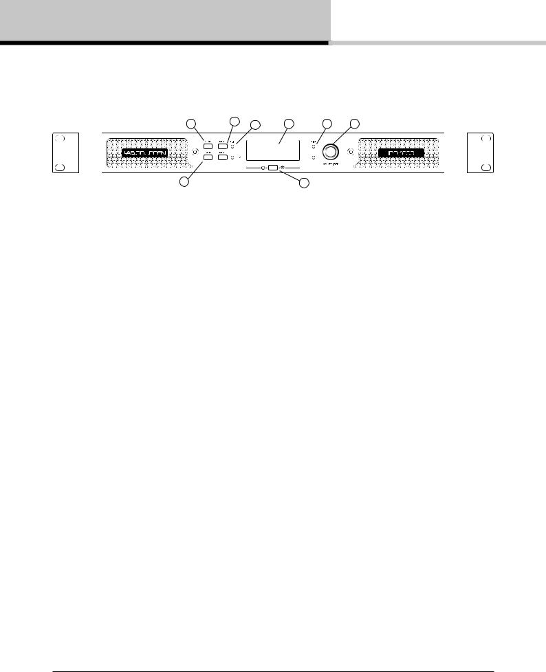
The following indicators and controls are available on the front panel:
1 MENU - Selects MENU mode and confirms a given preset name.
2 BACK - Moves backward through menu layers in MENU mode.
3 MUTE - Mutes corresponding channel as indicated.
4 SIG - Illuminates green when signal is present. Illuminates red when signal is clipping (pre input mixer).
5 POWER - LED indicates STANDBY (red); off when amplifier is ON.
6 LIM (limit) - Illuminates when the amplifier limits the signal. Limiting is engaged when the channel:
•Reaches the selected voltage limit
•Rail voltage sags below the selected threshold (both LEDs flash rapidly for 1.5 sec)
•Maximum current output reached
•Mains voltage cannot maintain full rail voltage
7ADJUST/SET (Rotary Encoder) - Rotation moves through the menu and adjusts the currently selected parameter when in setup mode. Pressing down on the knob selects a given parameter or advances further into the menu. In operating mode, rotation of the ADJUST/SET encoder adjusts output gain (outputs ganged).
8BACKLIT DISPLAY - In operating mode, the display shows the following values and status indicators:
•Level - Horizontal VU meters for each channel
•Device name and Preset name
In setup mode, the display shows the currently selected menu locations and parameters. For more information on DSP setup procedures, please refer to Section 10: IntelliDrive Controller Set-up and DSP Configuration.
8 IPD SERIES Operation Manual rev 1.0.0
3. Rear panel
3. Rear panel
1 |
2 |
5 |
|
|
3 |
4 |
6 |
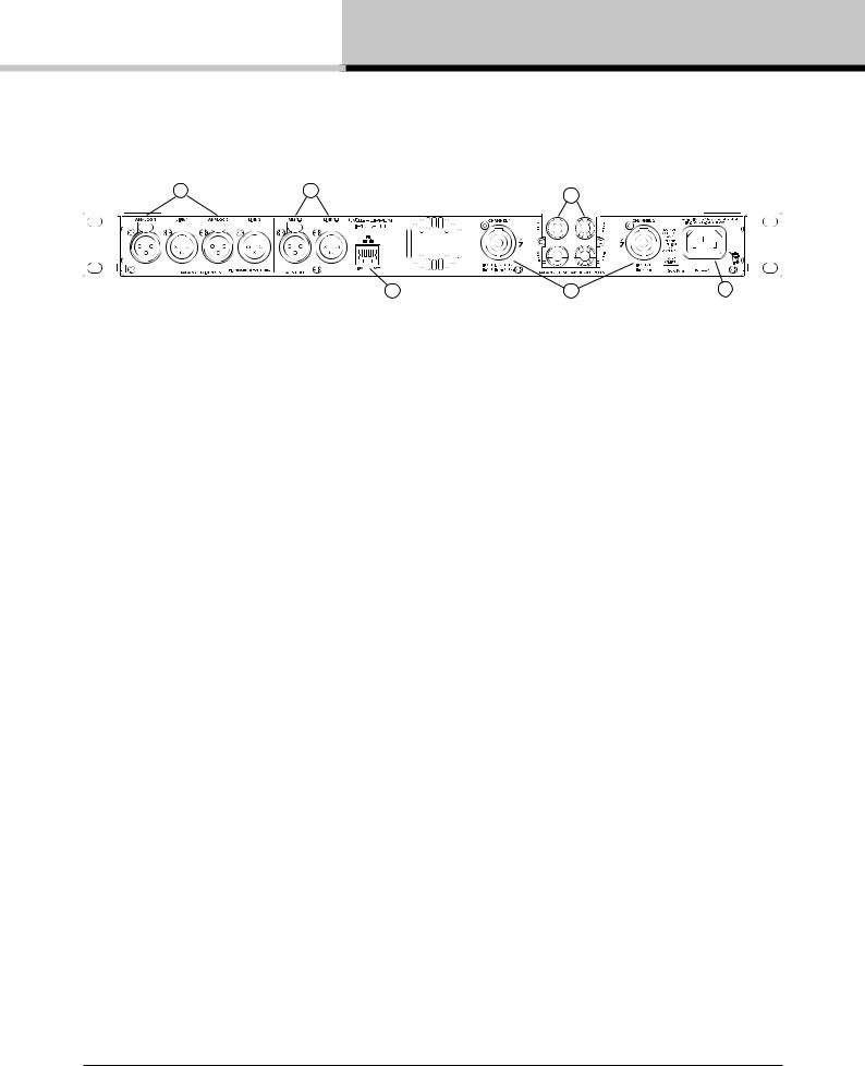
The following indicators and controls are available on the rear panel:
1ANALOG INPUTS and LINK - XLR-F input connectors provided for each channel, with XLR-M link output connectors.
2AES3 INPUT and LINK - AES3 digital inputs are on an XLR-F connector with a link output on an XLR-M connector.
3NETWORK (Ethernet) - An RJ45 jack is supplied for connection to an Ethernet network for external control and monitoring, either by a direct wired connection or via an external WiFi router to an iPad or tablet.
LEDs below the connector indicate valid network connection (LINK) and network activity (ACT). When several IPDs are connected to a network, a switch with a built-in DHCP server should be used.
4speakON OUTPUT CONNECTORS - Both channel outputs are available on a four-pole connector at the left; either channel 1 or both channels 1 and 2 may be connected. Only channel 2 is available on the connector to the right.
5 BINDING POST CONNECTORS - Connectors for channel 1 and channel 2.
6AC LINE INPUT - A locking IEC receptacle accepts the AC line input at 50 Hz or 60 Hz, 100 V - 240 V. Use an IEC cable with the proper connector for country of use.
IPD SERIES Operation Manual rev 1.0.0 |
9 |

4. Signal flow block diagram
4. Signal flow block diagram
The below diagram shows the signal flow from inputs to outputs:
|
|
|
|
|
|
|
|
|
Clip Limiter |
|
Analog 1 |
Input 1 |
Input 1 |
Input 1 |
X-Over |
Output 1 |
Output 1 |
Output 1 |
SCVPL |
IDEEA |
|
Levels |
EQ |
delay |
Levels |
EQ |
Delay |
Amplifier |
||||
|
|
|
||||||||
Analog 2 |
Input |
|
|
|
|
|
Rail Sense Limiter |
PSU |
||
AES 1 |
Mixer |
|
|
|
|
|
||||
|
|
|
|
|
|
|
|
|||
|
|
|
|
|
|
|
|
|
||
AES 2 |
Input 2 |
Input 2 |
Input 2 |
X-Over |
Output 2 |
Output 2 |
Output 2 |
SCVPL |
IDEEA |
|
Levels |
EQ |
delay |
Levels |
EQ |
Delay |
Amplifier |
||||
|
|
|
||||||||
Clip Limiter
5. Amplifier installation
5.1. Unpacking and visual check
Every Lab.gruppen amplifier is carefully tested and inspected before leaving the factory and should arrive in perfect condition. If any damage is discovered, please notify the shipping carrier immediately. Save the packing materials for the carrier’s inspection and for any future shipping.
5.2. Rack installation
IPD 1200 - Depth is 272 mm (10.7”) rack ear to back panel. Weight is approximately 4.6 kg (10.1 lbs). Rear support brackets are included and use is recommended in all applications.
IPD 2400 - Depth is 360 mm (14.2”) rack ear to back panel. Weight is approximately 6.2 kg (13.7 lbs). Rear support brackets are included and use is recommended in all applications.
5.3. Cooling requirements
Please ensure that there is sufficient space in the front and the rear of each amplifier to allow for a free flow of air. No doors or covers should be mounted either in the front or rear of the amplifiers. Amplifiers may be stacked directly on top of each other with no spacing, though some spacing may enable more convenient installation of rear cabling. Refer to the Thermal Dissipation charts in Section 15.2 for thermal dissipation values when installing large numbers of amplifiers in enclosed spaces.
10 IPD SERIES Operation Manual rev 1.0.0
6. Amplifier connections
6. Amplifier connections
6.1. AC line input / operating voltage
All IPD Series amplifiers have a universal power supply that operates on mains from 100 - 240 V at 50 or
60 Hz. The IEC receptacle on the rear panel accepts the supplied IEC cord which terminates in a connector plug appropriate for the country of sale. When AC power is connected, the amplifier goes into standby (red indication on standby LED). The amplifier may be turned on by pressing the front power button or remotely using the IntelliDrive Controller software.
Signal ground is floating via a resistor to chassis, and therefore grounding is automatic. For safety reasons,  never disconnect the earth (ground) pin on the AC power cord. Use balanced input connections to avoid hum
and interference.
6.2. Audio inputs
Analog inputs - Analog inputs are available on two standard XLR-F latching connectors. The inputs are electronically balanced. The impedance is 20 kohms, and the inputs can accept a maximum input level of +26 dBu. Polarity is as follows:
Pin 1 = screen (shield), pin 2 = positive (+), pin 3 = negative (-).
Analog links - Two latching XLR-M connectors are fitted adjacent to the analog input connectors and are paralleled to the respective input connectors; they provide an unprocessed analog loop-through signal to feed additional IPD Series units or other equipment.
AES3 inputs - A latching XLR-F connector accepts an AES3 digital audio signal. Input impedance is 110 ohms. Ensure that 110 ohm digital audio cables are used; standard XLR microphone cables are rarely suitable for reliable digital audio transmission.
Note: AES3 is a stereo digital format, and therefore both inputs are fed via a single connector. Selection of the analog or digital inputs is made via the front panel display or IntelliDrive Controller software.
AES3 link - A latching XLR-M connector is fitted adjacent to the AES3 input connector. This is an active link which sends an unprocessed AES3 loop-thru to feed additional IPD units. The design requires no termination load when the unit is the last connected.
IPD SERIES Operation Manual rev 1.0.0 |
11 |
 Loading...