


IPD 2400
Rev. 2.2.0
Item no. QSG-IPD
IPD SERIES
Touring and Installation Amplifiers
Quick Start Guide
クイックスタート・ガイド
Guide de prise en main
Das Wichtigste in Kürze
Guía de Inicio Rápido
1

Contents
3
English - Quick start guide
11
Chinese -
19
Japanese -
27
French - Guide de prise en main
35
German - Das Wichtigste in Kürze
43
Spanish - Guía de Inicio Rápido
クイックスタート・ガイド
2
Introduction
Lab.gruppen IPD Series ampliers provide exceptionally high power density and powerful integrated DSP features, making them suitable for a
broad range of installed and touring sound applications. All IPD Series ampliers feature both analog and AES3 inputs with link outputs; input
mixing; comprehensive DSP functions (crossover, parametric EQ, delay and limiter control); network control via Ethernet on Cat-5 cable or using
suitable WiFi access point; IntelliDrive™ Controller software and iPad native app; comprehensive front-panel display and dedicated mute buttons;
and both binding post and Neutrik speakON output connectors.
The information contained in this Quick Start Guide is sufcient for proper installation of IPD Series ampliers, and for conguration of settings
in typical applications. Please refer to the full Operation Manual for detailed information on maintenance, cooling requirements, warranty, and
conguration for complex installations.
Except as specically noted, all features, values and connections are identical for the IPD 1200 and IPD 2400.
Important safety instructions
1. Read these instructions.
2. Keep these instructions.
3. Heed all warnings.
4. Follow all instructions.
5. Do not use this apparatus near water.
6. Clean only with a dry cloth.
7. Do not block any ventilation openings. Install in accordance with the
manufacturer’s instructions.
8. Do not install near any heat sources such as radiators, heat registers,
stoves, or other apparatus (including ampliers) that produce heat.
9. Do not defeat the safety purpose of the polarized or grounding-type
plug. A polarized plug has two blades with one wider than the other.
A grounding-type plug has two blades and a third grounding prong.
The wide blade or the third prong is provided for your safety. If the
provided plug does not t into your outlet, consult an electrician for
replacement of the obsolete outlet.
10. Protect the power cord from being walked on or pinched, particularly
at plugs, convenience receptacles, and the point where they exit
from the apparatus.
11. Only use attachments/accessories specied by the manufacturer.
12. Use only with a cart, stand, tripod, bracket, or table specied by the
manufacturer, or sold with the apparatus. When a cart is used, use
caution when moving the cart/apparatus combination to avoid injury
from tip-over.
13. Unplug this apparatus during lightning storms or when unused for
long periods of time.
14. Refer all se r v icing to qualie d servic e perso nnel. Servici ng is requ ired
when the apparatus has been damaged in any way, such as
power-supply cord or plug is damaged, liquid has been spilled or
objects have fallen into the apparatus, the apparatus has been
exposed to rain or moisture, does not operate normally, or has been
dropped.
15. WARNING: To reduce the risk of re of electric shock, do not expose
this apparatus to rain or moisture.
16. Do not expose this equipment to dripping or splashing and ensure
that no objects lled with liquids, such as vases, are placed on the
equipment.
17. Do not connect the unit’s output to any other voltage source, such
as battery, mains source, or power supply, regardless of whether the
unit is turned on or off.
18. Do not remove the top (or bottom) cover. Removal of the cover will
expose hazardous voltages. There are no user serviceable parts
inside and removal may void the warranty.
19. An experienced user shall always supervise this professional audio
equipment, especially if inexperienced adults or minors are using
the equipment.
Standard
This equipment conforms to the
requirements of the EMC Directive
2004/108/EC and the requirements of
the Low Voltage Directive 2006/95/EC.
Standards applied: EMC Emission
EN55103-1, E3
EMC Immunity EN55103-2, E3, with S/N
below 1% at normal operation level.
Electrical Safety EN60065, Class I.
This equipment is tested and listed
according to the U.S. safety standard
ANSI/ UL 60065 and Canadian safety
standard CSA C22.2 NO. 60065. UL
made the tests and they are a Nationally
Recognized Testing Laboratory (NRTL).
Explanation of graphic symbols
The lightning bolt triangle is used to
alert the user to the presence of
un-insulated “dangerous voltages”
within the unit’s chassis that may be
of sufcient magnitude to constitute a
risk of electric shock to humans.
The exclamation point triangle is used to
alert the user to presence of important
operating and service instructions in the
literature accompanying the product.
3
Warning
Installation
To reduce risk of re or electric shock, do not expose this apparatus
to rain or moisture.
Do not expose this system/apparatus to dripping or splashing and
ensure that no objects lled with liquids, such as vases, are placed on
the apparatus.
This apparatus must be connected to a mains socket outlet with a
protective earthing connection.
The mains plug is used as a disconnect device and shall remain
readily operable.
To prevent electric shock do not remove top or bottom covers. No user
servicable parts inside. Refer servicing to qualied service personnel.
To completely disconnect this equipment from the AC mains,
disconnect the power supply cord plug from the ac receptacle. The
mains plug of the power supply cord shall remin readily operable.
Radio interference
A sample of this product has been tested and complies with the limits
for the European Electro Magnetic Compatibility (EMC) directive. It also
has been tested and found to comply with the limits for a Class A
digital device, pursuant to Part 15 of the FCC Rules. These limits are
designed to provide reasonable protection against harmful interference
from electrical equipment. This product uses radio frequency energy
and, if not used or installed in accordance with these operating
instructions, may cause interference to other equipment, such as
radio receivers. However, there is no guarantee that interference will
not occur in a particular installation. If this equipment causes harmful
interference to radio or television reception (determined by turning the
equipment on and off), the user may be able to correct the interference
by one or more of the following measures:
• Check if the affected unit complies with the EMC limits for immunity,
(CE-labeled). If not, address the problem with the manufacturer
or supplier. All electrical products sold in the EC must be approved
for immunity against electromagnetic elds, high voltage ashes,
and radiointerference.
• Consult the dealer or an experienced radio/TV technician for help.
• Reorient or relocate the antenna.
• Increase the separation between the equipment and receiver.
IPD 1200 – Depth is 272 mm (10.7 in) rack ear to back panel. Weight is
approximately 4.6 kg (10.1 lbs). Use of rear support brackets (optional)
is not necessary for xed installations but should be considered for
very demanding touring applications.
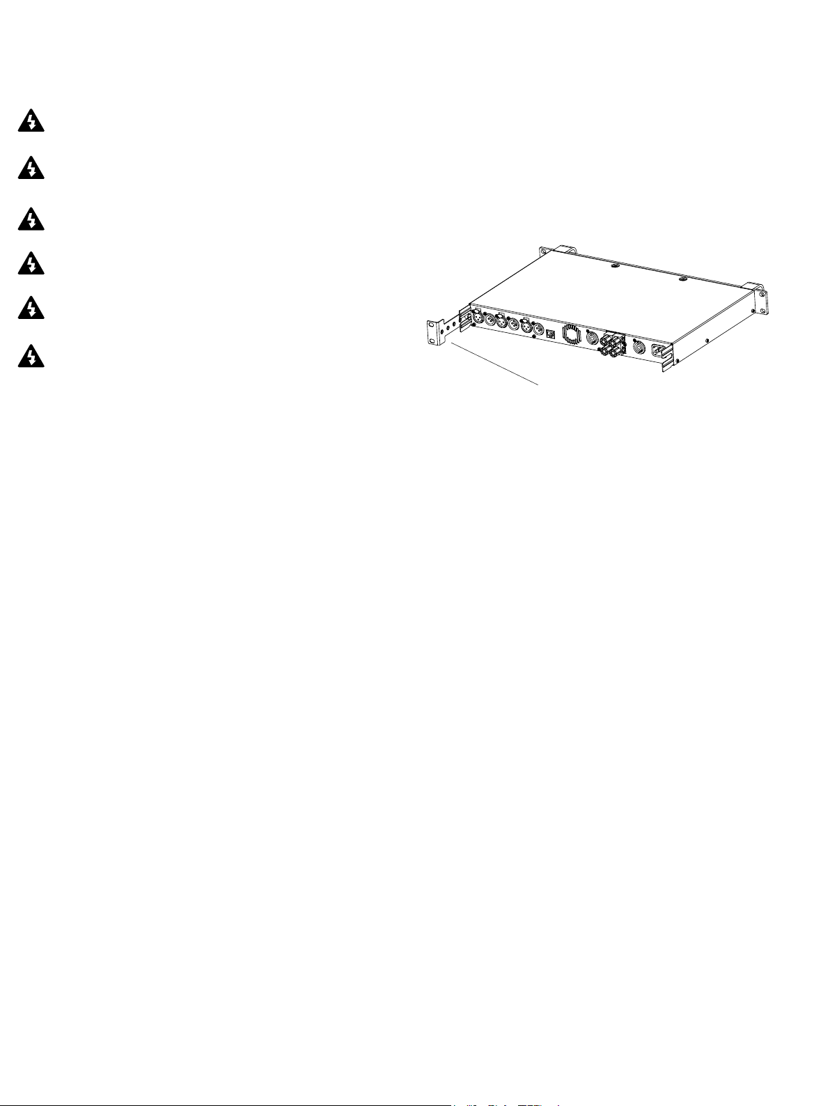
IPD 2400 – Depth is 360 mm (14.2 in) rack ear to back panel. Weight
is approximately 6.2 kg (13.7 lbs). Rear support brackets are included
and use is recommended in all applications.
Rear Support Bracket
Cooling
Please ensure that there is sufcient space in the front and the rear of
each amplier to allow for a free ow of air. No doors or covers should
be mounted either in the front or rear of the ampliers. Ampliers may
be stacked directly on top of each other with no spacing, though some
spacing may enable more convenient installation of rear cabling.
Refer to the full Operation Manual for thermal dissipation value when
installing large numbers of ampliers in air conditioned spaces.
Operating voltage
All IPD Series ampliers have a universal power supply that operates
on mains from 100 – 240 V at 50 or 60 Hz. The IEC receptacle on
the rear panel accepts the supplied IEC cord which terminates in a
connector appropriate for the country of sale. When AC power is
connected, the amplier goes into standby (red indication on standby
LED). The amplier may be turned on by pressing the front power
button or remotely using the IntelliDrive Controller software.
For customers in Canada
This Class B digital apparatus complies with Canadian ICES-003.
Français: Cet appareil numérique de la classe B est conforme à la
norme NMB003 du Canada.
Unpacking and visual checks
Every Lab.gruppen amplier is carefully tested and inspected before
leaving the factory and should arrive in perfect condition. If any
damage is discovered, please notify the shipping carrier immediately.
Save the packing materials for the carrier’s inspection and for any
future shipping.
Grounding
Signal ground is oating via a resistor to chassis, and therefore
grounding is automatic. For safety reasons, never disconnect the earth
(ground) pin on the AC power cord. Use balanced input connections
to avoid hum and interference.
4
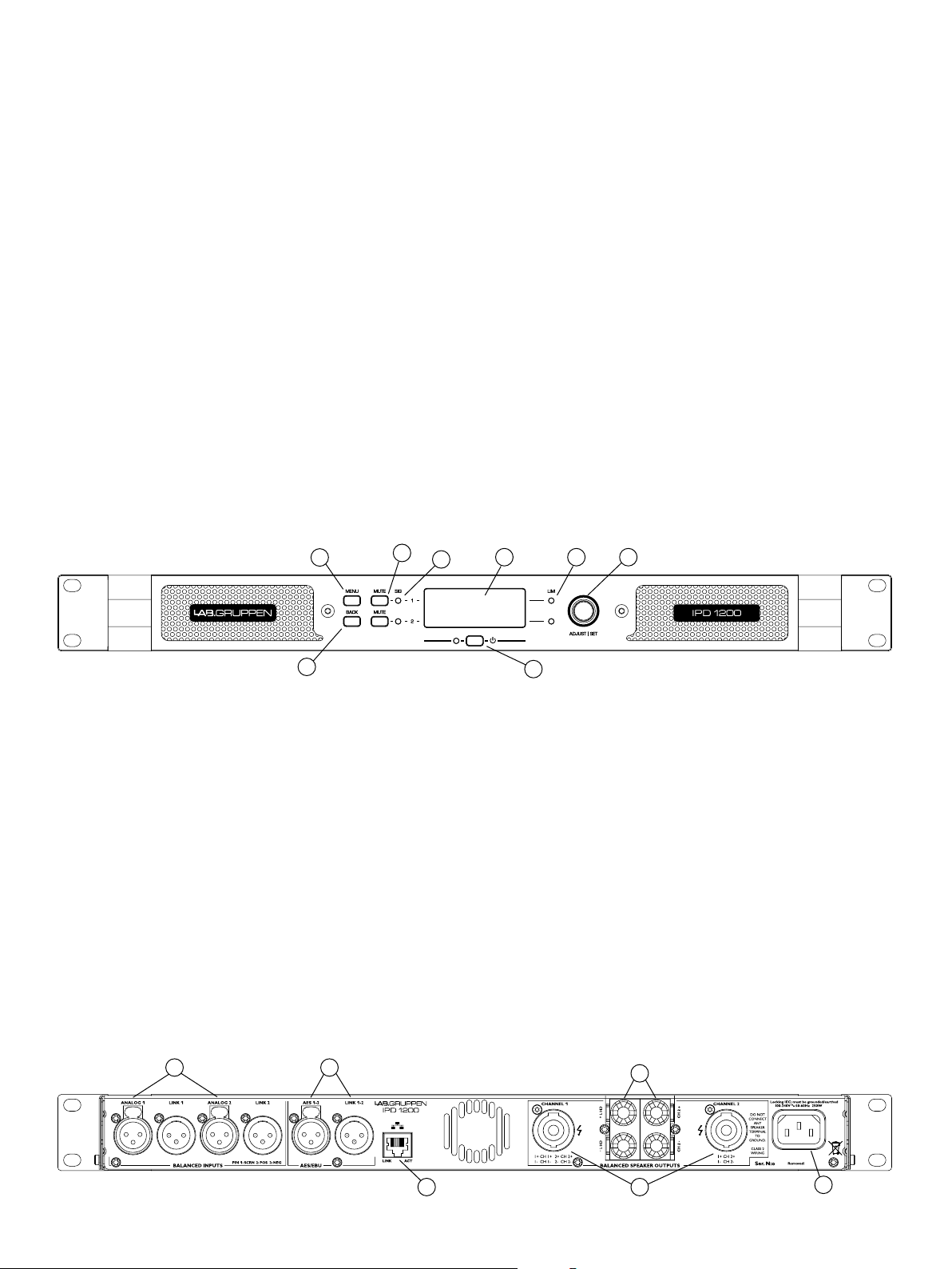
Front panel
The following indicators and controls are available on the front panel:
1 MENU – Selects MENU mode and conrms a given preset name.
2 BACK – Moves backward through menu layers in MENU mode.
3 MUTE – Mutes corresponding channel as indicated.
4 SIG – Illuminates green when signal is present. Illuminates red when
signal is clipping (pre input mixer)
5 POWER – Indicates STANDBY (red)
6 LIM (limit) – Illuminates when the amplier limits the signal.
Limiting is engaged when the channel:
• Reaches the selected voltage limit
• Rail voltage sags below the selected threshold (both LEDs ash
rapidly for 1.5 sec)
• Maximum current output reached
• Mains voltage cannot maintain full rail voltage
1
3
4
7 ADJUST/SET (Rotary Encoder) – Rotation moves through the menu
and adjusts the currently selected parameter when in setup mode.
Pressing down on the knob selects a given parameter or advances
further into the menu.
In operating mode, rotation of the ADJUST/SET encoder adjusts
output gain (outputs ganged).
8 BACKLIT DISPLAY
In operating mode, the display shows the following values and status
indicators:
• Level – Horizontal VU meters for each channel
• Device name and Preset name
In setup mode, the display shows currently selected menu locations
and parameters. For more information on DSP setup procedures,
please refer to the Operation Manual.
6 78
2
Rear panel
The following connectors are available on the rear panel:
1 ANALOG INPUTS and LINK - XLR-F input connectors provided for
each channel, with XLR-M link output connectors.
2 AES3 INPUT and LINK – AES3 digital inputs are on an XLR-F
connector with a link output on an XLR-M connector.
3 NETWORK (Ethernet) – An RJ45 jack is supplied for connection
to an Ethernet network for external control and monitoring, either by
a direct wired connection or via an external WiFi router to an iPad or
tablet. LEDs below the connector indicate valid network connection
(LINK) and network activity (ACT).
1 2
5
4 speakON OUTPUT CONNECTORS – Both channel outputs are
available on a four-pole connector at the left; either channel 1 or both
channels 1 and 2 may be connected. Only channel 2 is available on
the connector to the right.
5 BINDING POST CONNECTORS – Connectors for channel 1 and
channel 2.
6 AC LINE INPUT – A locking IEC receptacle accepts the AC line
input, 50 Hz or 60 Hz, 100 V – 240 V. Use an IEC cable with the proper
connector for country of use.
5
3 4
5
6
Input connections
Analog Inputs
Analog inputs are available on two standard XLR-F latching connectors.
The inputs are electronically balanced. The impedance is 20 kohms, and
the inputs can accept a maximum input level of +26 dBu.
Polarity is as follows:
Pin 1 = screen (shield), pin 2 = positive (+), pin 3 = negative (-).
Analog Links
Two latching XLR-M connectors are adjacent to the analog input
connectors and are paralleled to the input connectors to provide an
unprocessed analog loop-through to feed additional IPD Series units
or other equipment.
AES3 Inputs
A latching XLR-F connector accepts an AES3 digital audio signal. Input
impedance is 110 ohms. (Ensure that 110 ohm digital audio cables are
used; standard XLR microphone cables are rarely suitable for reliable
digital audio transmission.)
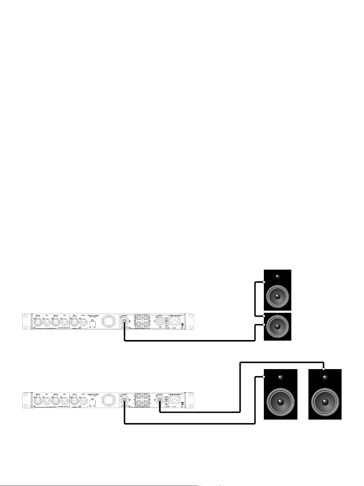
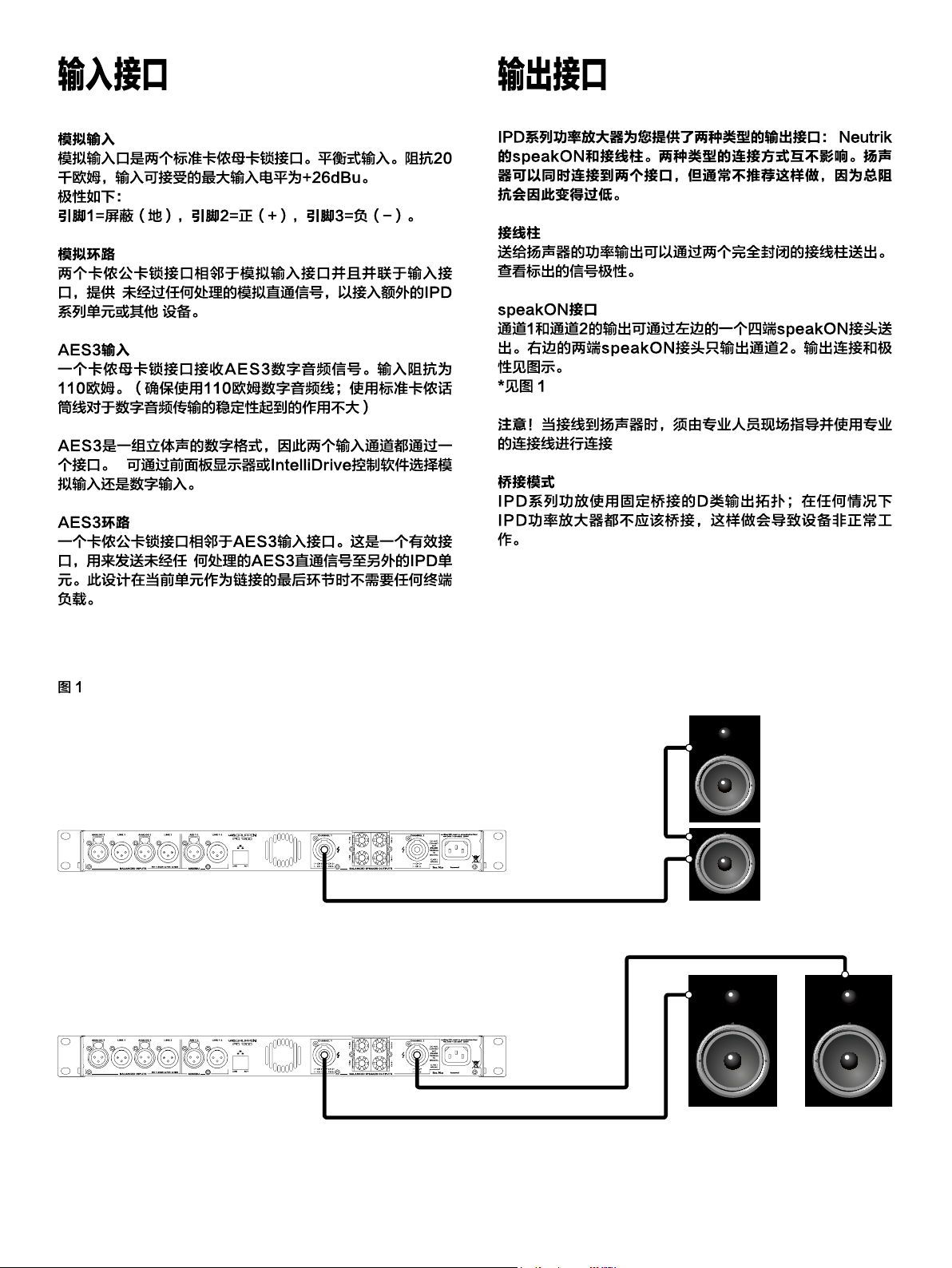
Output connections
Two types of power output connections are available on IPD
Series ampliers: Neutrik speakON and binding post. The
two types are connected in parallel. Loudspeakers may be
connected to both at the same time, but this is generally not
recommended as total impedance may be too low.
Binding Posts
Power outputs for loudspeaker connection are available on two fully
enclosed binding posts. Observe signal polarity as indicated.
speakON Connectors
Outputs for both channel 1 and channel 2 are available on a four-pole
speakON connector to the left. The two-pole speakON to the right
connect to output 2 only. See diagram for output connection and
polarity.
*see g 1
NOTE! When connecting wiring to Speaker Terminals, the installation
shall be made by an instructed person or ready-made leads or cords
shall be used
AES3 is a stereo digital format, and therefore both inputs are fed via a
single connector. Selection of the analog or digital inputs is made via
the front panel display or IntelliDrive Controller software.
AES3 Link
A latching XLR-M connector is tted adjacent to the AES3 input
connector. This is an active link which sends an unprocessed
AES3 loop-thru to feed additional IPD units. The design requires no
termination load when the unit is the last connected.
Fig 1
Bridge Mode
The IPD Series employs an inherently bridged Class D output topology;
Under no circumstances should the IPD Amplier be bridged, this may
cause undesired operating performance.
Channel 1 sent
through to top box.
Channel 1 and 2
Channel 2
Channel 1
6
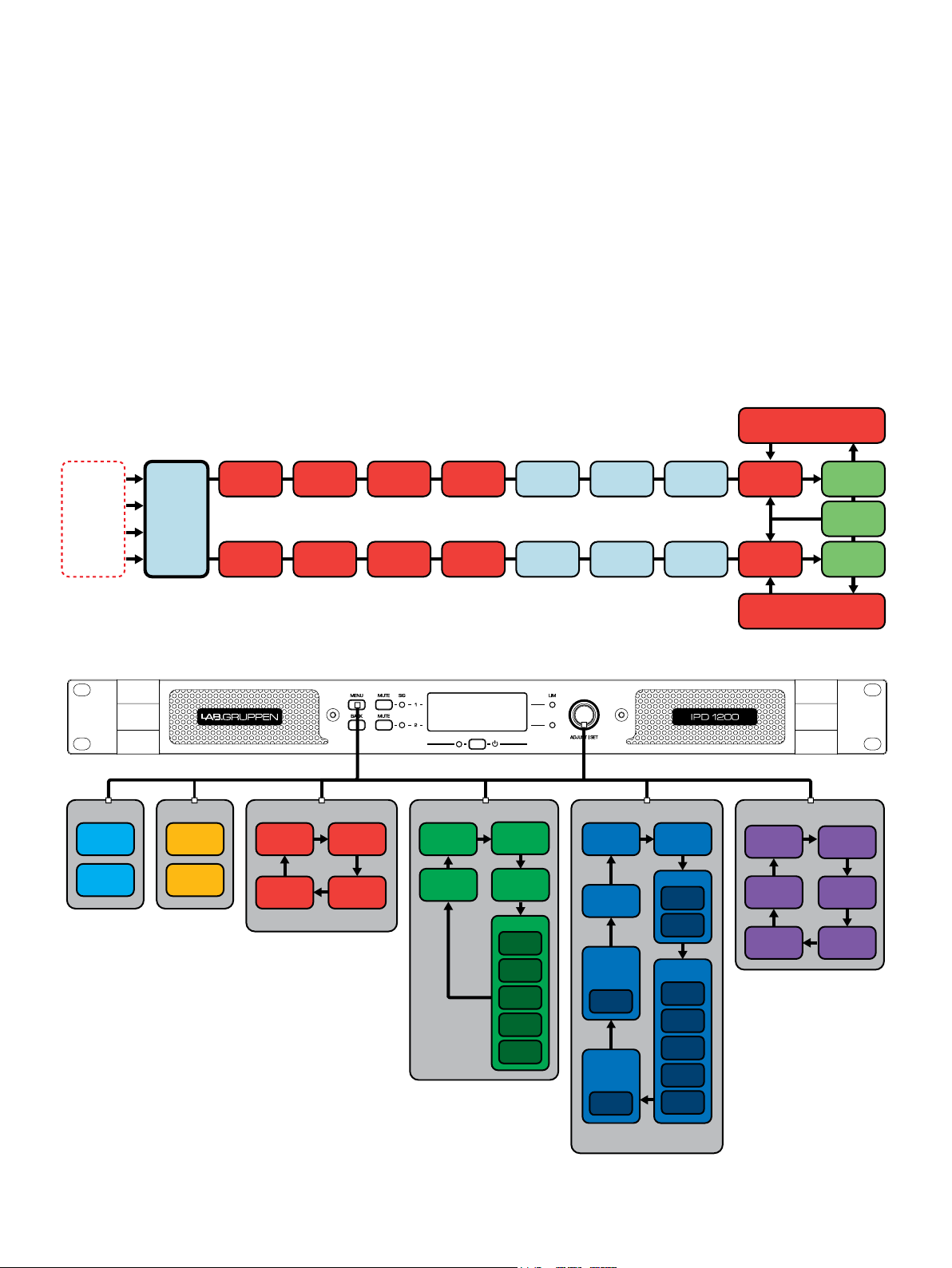
DSP configuration
Analog 1
Analog 2
AES 1
AES 2
Input 1
Levels
Input 1
EQ
Input 1
delay
Output 1
Levels
Output 1
EQ
IDEEA
Amplifier
Output 1
Delay
Clip Limiter
Clip Limiter
Rail Sense Limiter
SCVPLX-Over
Input 2
Levels
Input 2
EQ
Input 2
delay
Output 2
Levels
Output 2
EQ
IDEEA
Amplifier
PSU
Output 2
Delay
SCVPLX-Over
Input
Mixer
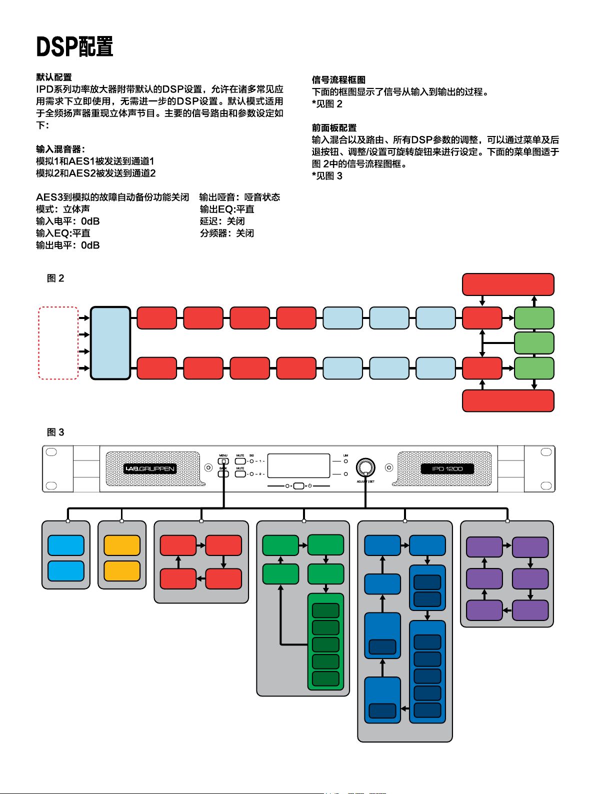
Default conguration
IPD Series ampliers are shipped with default DSP settings that allow
immediate use in many common applications with no need for further
DSP conguration. The default mode is suited for use with the stereo
program into full range loudspeakers. The main signal routing and
parameter settings are as follows:
Input mixer:
Analog 1 and AES1 are routed to Ch. 1
Analog 2 and AES 2 are routed to Ch. 2
AES3 to analog failover is OFF Output Mute: Muted
Mode: Stereo Output EQ: Flat
Input levels: 0 dB Delay: Off
Input EQ: Flat Crossover: Off
Output levels: 0 dB
Fig 2
Signal ow block diagram
The block diagram below shows the signal ow from inputs to outputs.
*see g 2
Front panel conguration
Input mixing and routing, as well as all DSP parameters, may be
congured using the Menu and Back buttons and the Adjust/Set rotary
encoder. The following menu tree is keyed to points in the signal ow
block in g 2.
*see g 3
Fig 3
Presets
Load
Store
Meters
Mixer
I/O Meters
Device Config
Mode
Lock
Device
Name
LCD
Brightness
Gain
Link
Input 1 & 2
Imput
Mixer
Delay
PEQ 1-10
Enable
Type
Freq
Gain
Q / BW
Output 1 & 2
Gain Delay
Link
Phase
Norm/
Invert
Limiter
Threshold
PEQ 1-10
X-Over
HPF
LPF
Enable
Type
Freq
Gain
Q / BW
Serial
Number
Temperature
Reading
Mac
Address
Device Info
Software
Version
H/W Version
IP Address
7
IntelliDrive Controller software
and network configuration
Software and App Downloads and Installation
For download of the IntelliDrive Controller software for Mac and
PC, please visit www.ipdseries.com. Instructions for installation are
available via this link.
The IntelliDrive Controller app for iPad Is available from Apple in the
App Store.
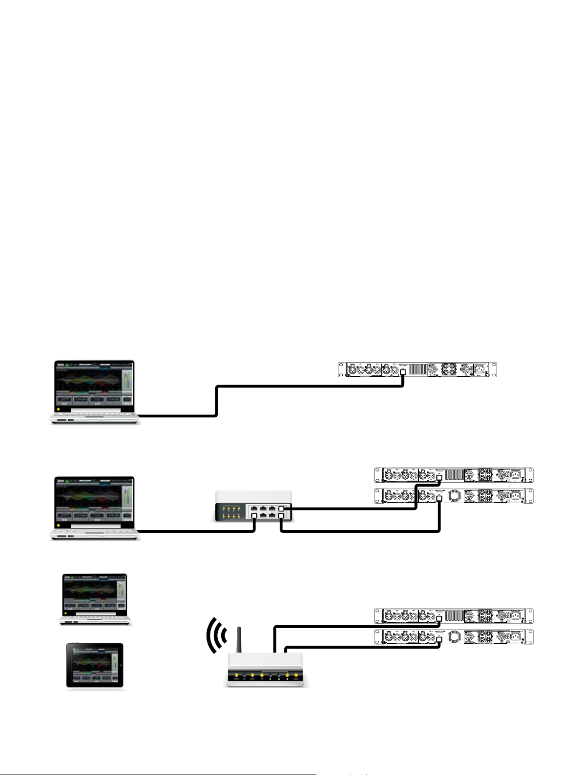
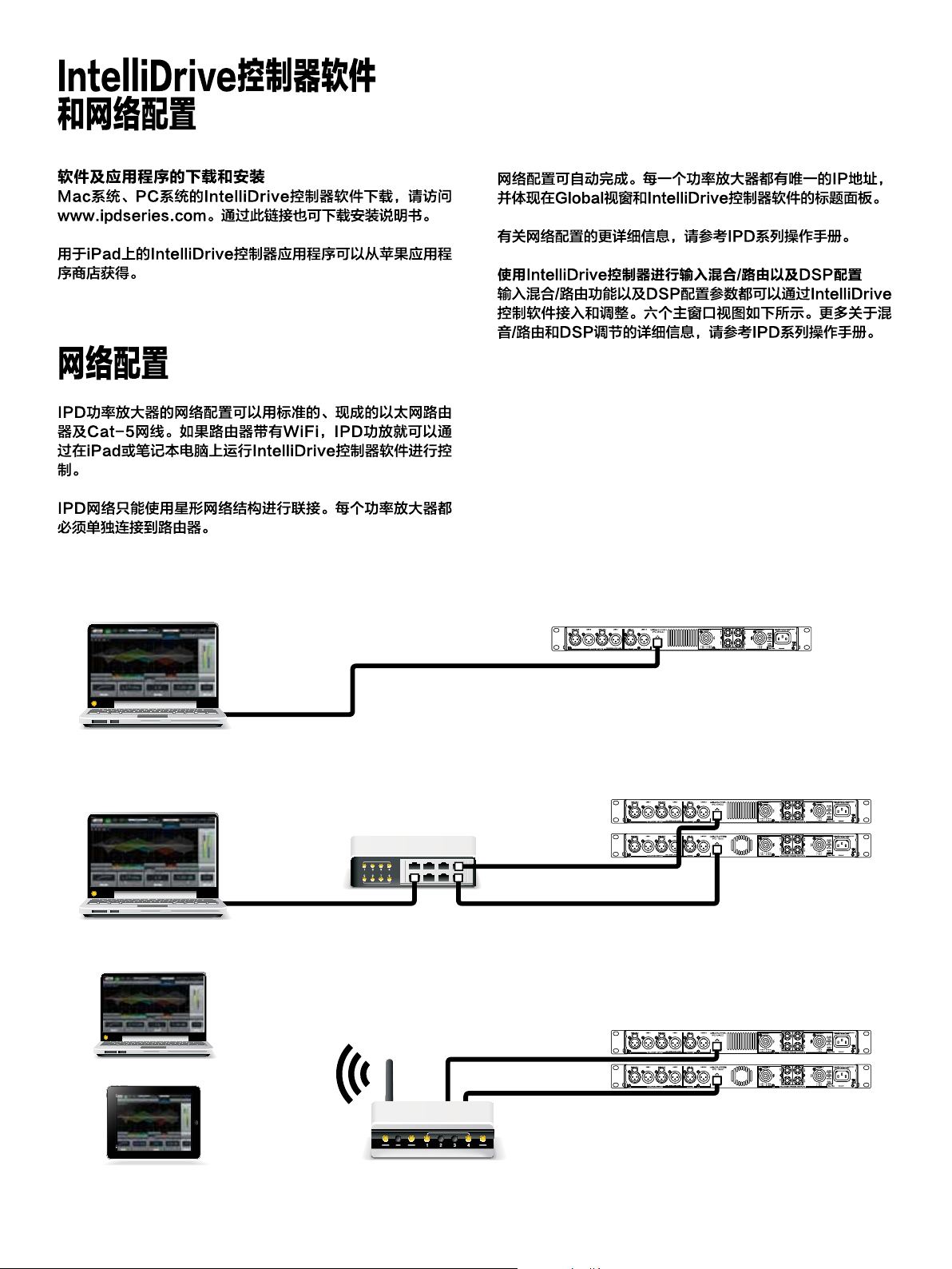
Network configuration
A network of IPD ampliers may be congured using standard,
off-the-shelf Ethernet router and Cat-5 cabling. If the router is
WiFi enabled, the IPD amplier network will be accessible using an
iPad or laptop computer running IntelliDrive Controller software.
The IPD network employs a star topology only. Each amplier must be
connected individually to the router.
Network conguration is automatic. Each amplier is identied by a
unique IP address, which is shown in the Global view and the device
header panel of IntelliDrive Controller.
For more detailed information on network conguration, please refer to
the IPD Series Operation Manual.
Input mixing/routing and DSP conguration using
IntelliDrive Controller
All input mixing /routing functions and DSP conguration parameters
are accessible and adjustable using IntelliDrive Controller software. The
device header panel appears at the top of each conguration window
for a selected device. For more detailed information on mixing/routing
and DSP adjustment, please refer to the IPD Series Operation Manual.
PC or Mac Computer
PC / Mac
iPad
Cat-5e
(direct connection may require
crossed cable or MDI/X capable NIC)
Network Router
Cat-5ePC / Mac
Cat-5e
iPad / Tablet
Wireless Router
8
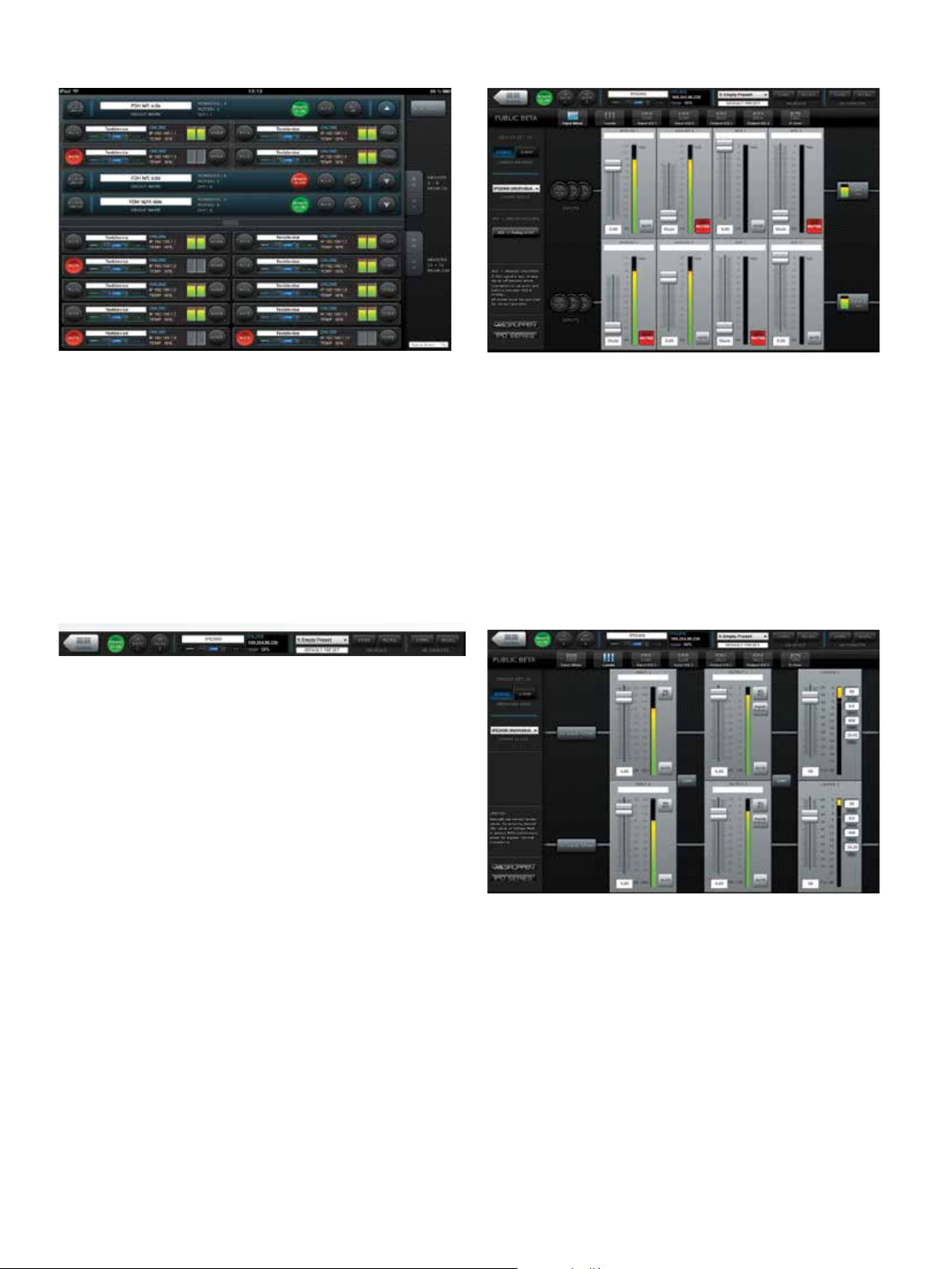
Global
Input Mixer
The Global view shows all devices on the network and accesses the
following functions:
• Naming devices (ampliers) and groups
• Forming groups of devices
• Creating and deleting groups
• Muting ampliers individually or in groups
• Power On/Off individually or in groups
• Monitoring of output levels
• Devices selected for a group are controlled simultaneously from any
of the device UI:s in that group.
Device Header
The device header panel appears at the top of each conguration
window for a selected device. The header panel accesses the following
functions and information:
Return to Global
• Power on/off
• Output mute (per channel)
• Device name
• Online/Ofine indication
• IP address
• Temperature reading
• Current preset
The Input Mixer view accesses the following functions:
• Device set-up (stereo or 2-way mode)
• Input mixing
• AES3 to analog failover on/off
Levels
Preset store and recall (device or computer)
The Levels view accesses the following functions:
• Input Mix Bus Levels
• Output levels
• Output limiters
• Linking of inputs and outputs.
9
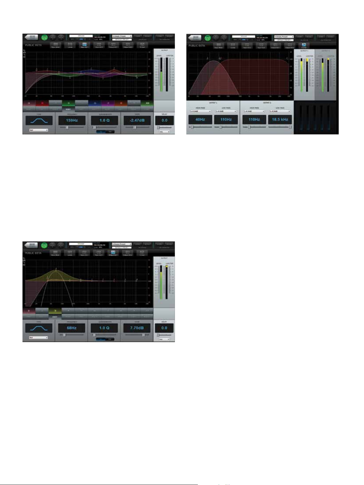
Input EQ
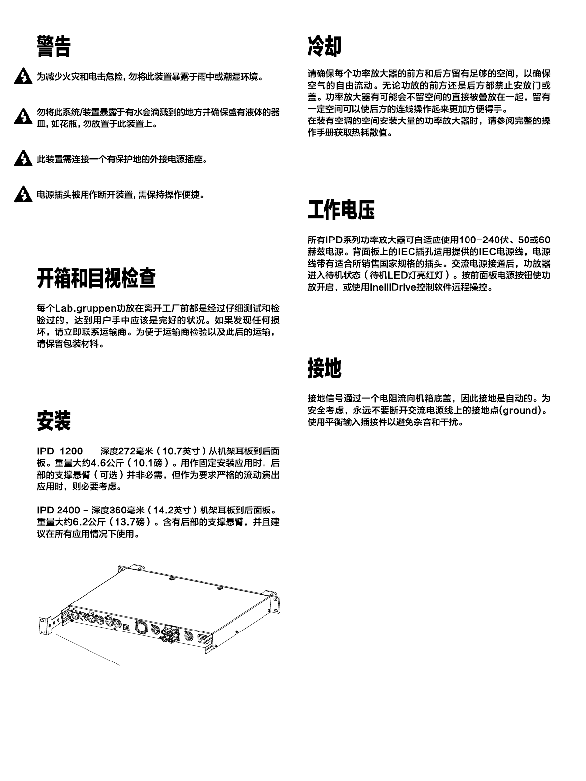
Crossover (X-Over)
Input EQ view is selectable per channel. Input EQ accesses the
following functions:
• Parametric equalizer (up to 10 bands)
• High-pass lter
• Low-pass lter
• Output level and limiting status
• Input delay (up to 2 sec)
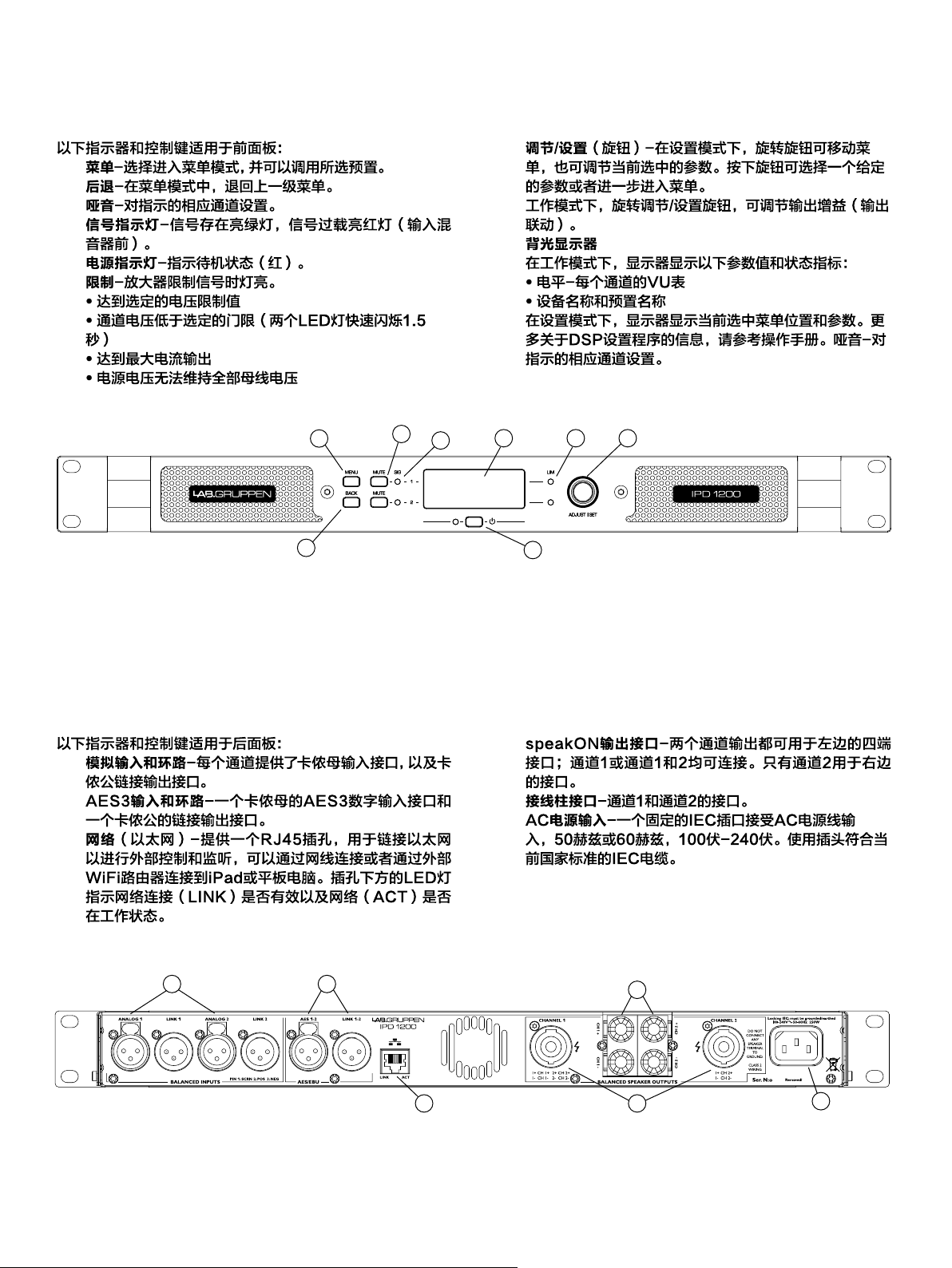
Output EQ
The Crossover view accesses the following functions for each output:
• High pass lter
• High pass lter type
• High pass lter cutoff frequency
• Low pass lter
• Low pass lter type
• Low pass lter cutoff frequency
• Output level and limiter status
Output EQ view is selectable per channel. The Output EQ view
accesses the following functions:
• Parametric equalizer (up to 10 bands)
• High-pass lter
• Low-pass lter
• Output level and limiting status
• Output delay (up to 2 sec)
10

引言
Lab.gruppen的IPD系列功放提供超高功率输出和强大的集成DSP特性,使它们广泛地应用于固定安装与流动演出领域。IPD系列
功放集中了多方面特性:模拟和AES3数字输入以及环路输出;输入混音;综合DSP功能(分频,参量EQ,延迟和限制控制);基
于以太网的网络控制,可用Cat-5线缆或使用适当的WiFi接入点;IntelliDrive控制器软件和iPad本地应用;前面板的综合显示和
专用哑音按钮压线柱和Neutrik speakON输出接口。
快速入门指南中包含了充足的正确安装IPD系列功放以及典型应用程序设置的信息。对于设备的维护、冷却需求、保修及相关复杂安
装配置的详细信息,请参考完整的操作手册。
除特别指出,IPD1200和IPD2400的所有功能、数值及插接件都是相同的。
重要的安全说明
阅读这些说明。
保存这些说明。
留意所有警告。
遵守所有说明。
不要在水边使用此设备。
请使用干布清洁。
不要遮挡任何通风口。依照厂商说明进行安装。
不要在任何热源附近安装,如散热器、热寄存器、火炉以及其
他产热装置(包括放大器)。
不要忽略极性或接地插头的安全目的。极性插头有两个叶片,
其中一个比另一个宽。接地插头有两个叶片和一个第三接地
叉。更宽的叶片和第三接地叉是为您的安全提供的。如果提供
的插头不适合您的插座,请咨询电工为您替换掉过时的插座。
避免电源线被踩踏或被捏挤,尤其插头处、插座处以及与设备
的连接处。
只使用厂商指定的附件/配件。
只使用厂商指定或厂商出售的推车、工作台、三脚架、支架和
桌子。使用推车时,移动推车/设备组合需注意,避免翻倒带来
的损伤。
雷暴期间或长时间不使用设备,请拔掉电源。
向有资格的服务人员获取所有需要的服务。设备产生如下任何
损坏时需要获取服务:电源线或插头损坏、液体洒漏或外界物
体进入设备、设备暴露在雨中或潮湿处、无法正常工作或设备
跌落。
警告:减少电击引起的火灾危险,勿将设备暴露在雨中或潮湿
处。
勿将设备至于水源滴溅处并且确保盛有液体的容器,像花瓶,
勿放置于设备上。
勿将此设备的输出接到任何其他电压源上,比如电池、电线电
源或电源,不管设备是开启状态还是关闭状态。
请勿移除顶部(或底部)机盖。移除机盖将会暴露危险电压。设
备内部无用户可用的部分,私自移除机盖将不予保修。
有经验的用户要对这样的专业音频设备进行监督,特别是当没
有使用经验的成年人或未成年人使用该设备时。
标准
此设备符合
电磁兼容指令2004/108/EC的要求
以及低电压指令2006/95/EC的要求
应用标准:
EMC排放EN55103-1,E3
EMC豁免权EN55103-2,E3,
正常操作水平下信噪比小于1%
电气安全EN60065,I级
此设备是根据
美国安全标准ANSI/UL60065和
加拿大安全标准CSA C22.2 NO.60065
测试并上市的
测试是由UL(保险商实验室)开展的
他们是一个全国性公认的测试实验室
(NRT L)
图形符号释义
带闪电的三角形用来警示用户:
设备的框架存在非绝缘危险电压
足够的量级对人身会产生电击危险
带感 叹号的 三 角用来 警 示用户:
产品附带文字册子内有重要的
操作和服务说明
为防止电击,请勿移除顶部或底部机盖。设备内部无用户可用的部
分。请提交有资格的维修人员维修。
为完全断开设备的交流电源,从交流插座处断开电源插头。电源线
的插头处需保持操作便捷。
引言
Lab.gruppen的IPD系列功放提供超高功率输出和强大的集成DSP特性,使它们广泛地应用于固定安装与流动演出领域。IPD系列
功放集中了多方面特性:模拟和AES3数字输入以及环路输出;输入混音;综合DSP功能(分频,参量EQ,延迟和限制控制);基
于以太网的网络控制,可用Cat-5线缆或使用适当的WiFi接入点;IntelliDrive控制器软件和iPad本地应用;前面板的综合显示和
专用哑音按钮压线柱和Neutrik speakON输出接口。
快速入门指南中包含了充足的正确安装IPD系列功放以及典型应用程序设置的信息。对于设备的维护、冷却需求、保修及相关复杂安
装配置的详细信息,请参考完整的操作手册。
除特别指出,IPD1200和IPD2400的所有功能、数值及插接件都是相同的。
此设备符合
电磁兼容指令2004/108/EC的要求
以及低电压指令2006/95/EC的要求
应用标准:
EMC排放EN55103-1,E3
EMC豁免权EN55103-2,E3,
正常操作水平下信噪比小于1%
电气安全EN60065,I级
此设备是根据
美国安全标准ANSI/UL60065和
加拿大安全标准CSA C22.2 NO.60065
测试并上市的
测试是由UL(保险商实验室)开展的
他们是一个全国性公认的测试实验室
(NRT L)
带闪电的三角形用来警示用户:
设备的框架存在非绝缘危险电压
足够的量级对人身会产生电击危险
带感 叹号的 三 角用来 警 示用户:
产品附带文字册子内有重要的
操作和服务说明
1.
2.
3.
4.
5.
6.
7.
8.
9.
10.
11.
12.
13.
14.
15.
16.
17.
18.
19.
11
后部支撑悬臂
12
前面板
后面板
1
2
3
4
6 78
5
1 2
3 4
13
5
6
Channel 1 and 2
Channel 2
Channel 1
14
Channel 1 sent
through to top box.
Clip Limiter
Analog 1
Analog 2
AES 1
AES 2
Presets
Load
Store
Input
Mixer
Meters
I/O Meters
Mixer
Input 1
Levels
Input 2
Levels
Device Config
Mode
Lock
Input 1
EQ
Input 2
EQ
Device
Name
LCD
Brightness
Input 1
delay
Input 2
delay
Gain
Link
Input 1 & 2
Imput
Mixer
Delay
PEQ 1-10
Enable
Type
Freq
Gain
Q / BW
Output 1
Levels
Output 2
Levels
Output 1
EQ
Output 2
EQ
Output 1 & 2
Gain Delay
X-Over
Link
Phase
Norm/
Invert
Limiter
PEQ 1-10
Enable
Output 1
Delay
Rail Sense Limiter
Output 2
Delay
HPF
LPF
Type
Freq
Gain
SCVPLX-Over
SCVPLX-Over
Clip Limiter
Device Info
Serial
Number
Temperature
Reading
Mac
Address
IDEEA
Amplifier
PSU
IDEEA
Amplifier
Software
Version
H/W Version
IP Address
15
Threshold
Q / BW
PC or Mac Computer
PC / Mac
iPad
Cat-5e
(direct connection may require
crossed cable or MDI/X capable NIC)
Network Router
Cat-5ePC / Mac
Cat-5e
iPad / Tablet
Wireless Router
16
 Loading...