


 Loading...
Operation Manual
PLM™ Series
Powered Loudspeaker Management™ systems
Rev 1.3.0
Item: OM-PLM
Important Safety Instructions
1. Important Safety Instructions
Before using the device, be sure to carefully read the Safety Instructions. Keep this document with the device at all times.
1.1Important Safety Instructions
1.Read these instructions.
2.Keep these instructions.
3.Heed all warnings.
4.Follow all instructions.
5.Do not use this apparatus near water.
6.Clean only with a dry cloth.
7.Do not block any ventilation openings. Install in accordance with the manufacturer’s instructions.
8.Do not install near any heat sources such as radiators, heat registers, stoves, or other apparatus (including amplifiers) that produce heat.
9.Do not defeat the safety purpose of the polarized or grounding-type plug. A polarized plug has two blades with one wider than the other. A grounding-type plug has two blades and a third grounding prong. The wide blade or the third prong is provided for your safety. If the provided plug does not fit into your outlet, consult an electrician for replacement of the obsolete outlet.
10.Protect the power cord from being walked on or pinched, particularly at plugs, convenience receptacles, and the point where they exit from the apparatus.
11.Only use attachments/accessories specified by the manufacturer.
12.Use only with a cart, stand, tripod, bracket, or table specified by the manufacturer, or sold with the apparatus. When a cart is used, use caution when moving the cart/apparatus combination to avoid injury from tip-over.
13.Unplug this apparatus during lightning storms or when unused for long periods of time.
14.Refer all servicing to qualified service personnel. Servicing is required when the apparatus has been damaged in any way, such as power-supply cord or plug is damaged, liquid has been spilled or objects have fallen into the apparatus, the apparatus has been exposed to rain or moisture, does not operate normally, or has been dropped.
15.Use the mains plug to disconnect the apparatus from the mains.
16.WARNING: To reduce the risk of fire of electric shock, do not expose this apparatus to rain or moisture.
17.Do not expose this equipment to dripping or splashing and ensure that no objects filled with liquids, such as vases, are placed on the equipment.
18.The mains plug of the power supply cord shall remain readily operable.
19.Do not connect the unit’s output to any other voltage source, such as battery, mains source, or power supply, regardless of whether the unit is turned on or off.
20.Do not remove the top (or bottom) cover. Removal of the cover will expose hazardous voltages. There are no user serviceable parts inside and removal may void the warranty.
21.An experienced user shall always supervise this professional audio equipment, especially if inexperienced adults or minors are using the equipment.
22.The US National Differences clause 16.3 requires that network cables must be flame rated VW-1.
To prevent electric shock do not remove top or bottom covers. No user serviceable parts inside, refer servicing to qualified service personnel.
à prévenir le choc électrique n’enlevez pas les couvercles. Il n’y a pas des parties serviceable à l’intérieur, tous reparations doit etre faire par personnel qualifié seulment.
To completely disconnect this equipment from the AC mains, disconnect the power supply cord plug from the AC receptacle. The mains plug of the power supply cord shall remain readily operable.
Pour démonter complètement l’équipement de l’alimentation générale, démonter le câble d’alimentation de son réceptacle. La prise d’alimentation restera aisément fonctionnelle.
1.2Standards
This equipment conforms to the requirements of the EMC Directive 2004/108/EC and the requirements of the Low Voltage Directive 2006/95/EC.
Standards applied: EMC Emission EN55103-1, E3
EMC Immunity EN55103-2, E3, with S/N below 1% at normal operation level. Electrical Safety EN60065, Class I
This equipment is tested and listed according to the U.S. safety standard ANSI/ UL 60065 and Canadian safety standard CSA C22.2 NO. 60065. Intertek made the tests and they are a Nationally Recognized Testing Laboratory (NRTL).
1.3Explanation of Graphical Symbols
The lightning bolt triangle is used to alert the user to the presence of un-insulated “dangerous voltages” within the unit’s chassis that may be of sufficient magnitude to constitute a risk of electric shock to humans.
The exclamation point triangle is used to alert the user to presence of important operating and service instructions in the literature accompanying the product.
PLM Series Operation Manual Rev 1.3.0 |
i |

Important Safety Instructions
1.4WARNING
To reduce risk of fire or electric shock, do not expose this apparatus to rain or moisture.
Pour réduire les risques de blessure ou le choc électrique, n’exposez pas l’appareil à la pluie ou à l’humidité.
Do not expose this system/apparatus to dripping or splashing and ensure that no objects filled with liquids, such as vases, are placed on the apparatus.
L’appareil ne doit pas être exposé à des egouttements d’eau ou des éclaboussures et de plus qu’aucun objet rempli de liquide tel que des vases ne doit pas être placé sur l’appareil.
This apparatus must be connected to a mains socket outlet with a protective earthing connection.
Cet appareil doi t être raccordé á une prise de courant qui est branchée à la terre.
The mains plug is used as a disconnect device and shall remain readily operable.
Lorsque la prise du réseau d’alimentation est utilisés comme dispositif de déconnexion, ce dispositif doit demeuré aisément accessible.
1.5CAUTION
To reduce the risk of fire or electric shock, do not remove screws. No user-serviceable parts inside. Refer servicing to qualified service personnel.
Pour réduire le risque d’incendie ou de choc électrique, ne pas retirer les vis. Aucune pièce réparable par l’utilisateur. Confier l’entretien àpersonnel qualifié.
1.6FCC Compliance Notice (Radio Interference)
A sample of this product has been tested and complies with the limits for the European Electro Magnetic Compatibility (EMC) directive. This equipment has also been tested and found to comply with the limits for a Class A digital device, pursuant to Part 15 of the FCC Rules. These limits are designed to provide reasonable protection against harmful interference from electrical equipment. This product uses radio frequency energy and if not used or installed in accordance with these operating instructions, may cause interference to other equipment, such as radio receivers.
This Class A digital apparatus complies with Canadian ICES-003.
Cet appareil numérique de la classe A est conforme à la norme NMB-003 du Canada.
However, there is no guarantee that interference will not occur in a particular installation. If this equipment does cause harmful interference to radio or television reception, which can be determined by turning the equipment on and off, the user is encouraged to try to correct the interference by one or more of the following measures:
Reorient or relocate the antenna.
Increase the separation between the equipment and receiver.
ii PLM Series Operation Manual Rev 1.3.0

Important Safety Instructions
Connect the equipment to an outlet on a circuit different from that to which the receiver is connected.
Check if the affected unit complies with the EMC limits for immunity, (CE-labeled). If not, address the problem with the manufacturer or supplier. All electrical products sold in the EC must be approved for immunity against electromagnetic fields, high voltage flashes, and radio interference.
Consult the dealer or an experienced radio/TV technician for help.
1.7User Responsibility
1.7.1Mains Connection Grounding
 Your apparatus must be connected to a grounded socket outlet.
1.7.2Speaker Output Hazard on Amplifiers
 Amplifiers are capable of producing hazardous output voltages. To avoid electrical shock, do not touch any exposed speaker wiring while the amplifier is operating. The external wiring connected to the speaker terminals shall be installed by a qualified person, or ready-made leads or cords of appropriate capacity shall be used.
 As the power output channels on amplifiers produce high voltage, do not connect or disconnect speaker cables when the mains power is on.
1.7.3Speaker Damage
Amplifier apparatus is very powerful and can be potentially dangerous to both loudspeakers and humans alike. Many loudspeakers can be easily damaged or destroyed by overpowering them. Always check the speaker’s continuous and peak power capabilities. Although the amplifiers attenuators can be used to reduce the overall gain, an increase of the input signal can result in full output power, which may cause damage to connected speakers.
1.7.4Maintenance
For safe and reliable operation, the dust filters on both sides of the front panel, behind the grilles, should be removed and cleaned regularly to ensure maximum airflow through the device.
 If the dust filters are not maintained there will be safety risks; for example, high internal temperatures could ignite the dust and start a fire. There is also a risk that the unit will malfunction since it is dependent on constant airflow from front to rear. If the dust filters are not clean and the unit malfunctions, any resulting problems will not be covered by the warranty.
PLM Series Operation Manual Rev 1.3.0 |
iii |

Table of Contents
1. Important Safety Instructions i
1.1 Important Safety Instructions i
1.2 Standards i
1.3 Explanation of Graphical Symbols i
1.4 WARNING ii
1.5 CAUTION ii
1.6 FCC Compliance Notice (Radio Interference) ii
1.7 User Responsibility iii
2. Welcome 1
2.1 Introduction 1
2.2 Main Features 1
2.3 Additional Documentation 3
3. Installation 4
3.1 Unpacking 4
3.2 Mounting 4
3.3 Cooling 6
3.4 Operating Voltage 6
3.5 Grounding 7
4. Product Overview 8
4.1 Front Panel Overview 8
4.2 Back Panel Overview 11
5. Operation and Performance 15
5.1 Operation Precautions 15
5.2 Power Output Performance 15
5.3 Amplifier and Load Protection Systems 17
5.4 Power Supply 24
6. Signal Flow and Lake® Processing 25
6.1 Signal Flow 25
6.2 Level Adjustments & Mute Points 25
6.3 Lake Processing and Control 27
6.4 Modules and Frames 27
6.5 Loudspeaker Processor Overview 28
6.6 Files and Presets 29
7. Front Panel Interface |
31 |
|
7.1 |
Overview |
31 |
7.2 |
Front Panel Key Lock |
32 |
7.3 |
Power Button |
33 |
iv PLM Series Operation Manual Rev 1.3.0

7.4 Mute Enable Button 33
7.5 Meter Button 33
7.6 Menu Button 33
7.7 Exit Button 34
7.8 Dynamic Buttons, Controls and LEDs 34
7.9 Warning and Fault Indications 39
7.10 Meter Mode 42
7.11 Menu Mode 46
8. Back Panel Interface 63
8.1 Speaker Outputs 63
8.2 Analog Inputs and Outputs 68
8.3 AES3 Digital I/O 70
8.4 RJ45 etherCON Network Connections 71
8.5 Power Inlet 72
9. Appendix 73
9.1 Faults and Warnings Overview 73
9.2 Maintenance 77
9.3 Factory Default Settings 77
9.4 Current Draw and Thermal Dissipation Specifications 78
9.5 Glossary of Terms, Acronyms and Abbreviations 82
10. Application Guide 85
10.1 Rack I/O Panels 85
10.2 Power Distribution 85
10.3 Gain Structure 86
10.4 Gain / Level Optimization 88
10.5 Speaker Configurations 91
10.6 Digital Audio Connections 92
10.7 Digital Clock Configuration 95
11. Technical Specifications 97
12. Warranty and Support 98
12.1 General 98
12.2 International Warranties 98
12.3 Technical Assistance and Service 98
12.4 Trademarks 99
PLM Series Operation Manual Rev 1.3.0 |
v |

Welcome
2. Welcome
2.1Introduction
Thank you for choosing the Lab.gruppen PLM Series of Powered Loudspeaker Management systems for your sound reinforcement needs. We are confident that you will be pleased with the performance, unique features, configuration flexibility, reliability, and long-term durability offered by this product.
For fast installation and use of this product, your welcome package includes a printed copy of the
PLM Series Quick Start & Field Reference Guide which contains the information required to safely install the product and place it in service. Control and editing features are accessible via the front panel interface or via the included Lake Controller software.
It is recommend that the Quick Start & Field Reference Guide and all product documentation on the included CD-ROM is reviewed to ensure familiarity with the various configuration and control options.
Thank you again for placing your confidence in Lab.gruppen products.
2.2Main Features
The PLM Series incorporates a number of sophisticated technologies to ensure the best possible performance and many years of reliable operation. The following section summarizes the benefits of each feature; additional information is available in the reference manuals.
2.2.1Amplifier Platform
The PLM Series power output section has expanded upon Lab.gruppen’s robust, road-proven
FP+ Series amplifiers. Features in common with the FP+ Series include extraordinary power density, patented Class TD® output stages, Regulated Switch Mode Power Supply (R.SMPS™), the high-efficiency Intercooler® copper-finned cooling system, and a full suite of protection features. Signal inputs are analog, AES digital, and Dante digital audio network; loop-through outputs or redundant pairs are provided for each input type.
Please refer to section 5.3 for further information.
2.2.2Amplifier DSP (Digital Signal Processor)
Various features of PLM Series devices are controlled by the on-board DSP, some of which are summarized in this section.
PLM Series Operation Manual Rev 1.3.0 |
1 |

Welcome
2.2.2.1 Input Gain (Sensitivity)
Input gain (sensitivity) is set in the digital domain for PLM Series devices, and may be controlled via the Lake Controller software or front-panel interface.
2.2.2.2 ISVPL™
The Inter-Sample Voltage Peak Limiter (ISVPL) tailors each power output to the characteristics of the connected load. Please refer to section 5.3.1 for further information.
2.2.2.3 Load Verification & Performance Monitoring
A comprehensive set of proprietary DSP-based tools are provided for load verification and real-time performance monitoring. These functions utilize LoadLibrary, a comprehensive database for each loudspeaker component of the connected load (usually one or more band-limited drivers in a multi-way system).
Using this data and a brief test signal, LoadSmart compares actual response to predicted response, identifying any malfunctioning components or connection errors. During the performance, SpeakerSafe™ monitors real-time load status, including temperatures of the PLM amplifier stages as well as magnets and voice coils of connected loudspeakers. This allows operators to avoid power compression and identify potential problems.
Please refer to the Lake Controller Operation Manual for detailed information on PLM Series load verification and real-time performance monitoring functionality.
2.2.3Lake Processing and Controller
PLM Series devices integrate seamlessly into the Lake Processing environment and are accessible via the Lake Controller software. Processing modules offer precise settings for gain, delay, crossover settings, equalization and limiting. Lake processing features incorporated in each module include Raised Cosine Equalization™, linear phase crossovers, and LimiterMax™ loudspeaker protection. The Super Module feature allows hardware processing modules in two or more separate devices to function as a single module in the Lake Controller software. Please refer to the Lake Controller Operation Manual for further information.
2.2.4Analyzer Plug-In
Lake Controller software provides integration with third-party real-time analyzers, providing simultaneous measurement display and EQ adjustment via the Lake Controller. Approved analyzers include Rational Acoustics Smaart 7 and WaveCapture Live Capture Light or Live-Capture Pro; additional third-party analyzers may be approved in the future.
Please refer to the Lake Controller Operation Manual for further information regarding the Analyzer plug-in and associated functionality.
2 PLM Series Operation Manual Rev 1.3.0

Welcome
2.2.5Dante™ Audio Network
PLM Series devices include Dante digital audio networking as standard. Utilizing the latest advances in Ethernet technology, Dante offers simplified system configuration and extremely low latency while delivering very high quality uncompressed digital audio across the Lake network. The Zen™ automatic configuration feature enables plug-and-play setup without third-party DHCP or DNS servers. Dante is compatible with high-bandwidth networks, allowing large numbers of audio channels to be distributed alongside control and analyzer data.
2.3Additional Documentation
This document, the PLM Operation Manual, serves as the primary reference source for detailed information on the installation and operation of PLM Series Powered Loudspeaker Management systems. It also provides detailed information on set-up and configuration using the front-panel interface.
If you intend to use the device as part of a networked system, or access features via the Lake Controller, please refer to the various supporting documents which can be located via these methods:
Start > Programs > Lake Controller > Documentation (after installing Lake Controller software)
On the Installer CD-ROM or the downloaded software installer
Online at: http://labgruppen.com/index.php/products/documentation/
PLM Series Operation Manual Rev 1.3.0 |
3 |

Installation
3. Installation
3.1Unpacking
Carefully open the shipping carton and check for any damage to the device or the supplied accessories. Every Lab.gruppen product is tested and inspected before leaving the factory and should arrive in perfect condition. If any damage is discovered, please notify the shipping company immediately. Only the consignee may initiate a claim with the carrier or their insurers for damage incurred during shipping. Save the carton and packing materials for the carrier’s inspection.
In addition to the PLM Series device, the shipping carton include the following items:
PLM Series Quick Start & Field Reference Guide
AC mains lead (power cable) with Neutrik® powerCON® connector
Rear brackets for additional rack support (pair) along with associated mounting hardware
Software Installer and Documentation CD-ROM
Please keep the original carton and associated packaging to facilitate shipping of the device should the need arise.
3.2Mounting
Airflow for cooling the device is from front panel (intake) to rear panel (exit). Please ensure that no object, such as rack doors or lids are placed at the front or rear of the rack to ensure that airflow is maximized. This device has no top or bottom vents and therefore may be stacked directly on top of each other.
Sufficient space should be available at the front of the rack to accommodate the handles, and at the rear to accommodate connectors and cables; allowance must be made for cable or loom bends within a rack.
3.2.1Rear Mounting
Two rear support brackets along with associated mounting hardware are included with the PLM, as shown in Figure 3-1; it is recommended that these are used wherever possible. Fit the brackets to the vertical rails at the rear of the rack. Figure 3-2 and Figure 3-3 show the fitting options for fixed and removable installation.
The support brackets are reversible and may be fitted to point either to the front or rear of the rack; the orientation used depends on the rack depth and position of the rear rack rails.
Two mounting methods are possible; note that the method shown in Figure 3-2 additionally provides extra security against unauthorized removal. For situations where rapid removal and replacement is required, the method shown in Figure 3-3 should be used.
4 PLM Series Operation Manual Rev 1.3.0
Installation
Figure 3-1: Rear Support Bracket and Mounting Hardware
Figure 3-2: Use the Washer for Fixed Installations
Figure 3-3: UseTube for Slide-On Installation
PLM Series Operation Manual Rev 1.3.0 |
5 |

Installation
3.3Cooling
3.3.1Overview
The PLM Series devices use a forced-air cooling system with airflow from front to rear, allowing high continuous power levels without thermal problems. Front-to-rear airflow is preferable as air at the front of a rack is cooler than that at the rear in nearly all situations; never attempt to reverse the airflow. The operation of the PLM’s cooling system is dependent on front-to-rear airflow; it will not function effectively with external airflow in the opposite direction.
 Make sure an adequate air supply is provided in front of the PLM, and that the rear of the PLM has sufficient space to allow air to escape. If the PLM is rack-mounted, never operate the unit with any front or rear rack doors or covers in position. It is recommended to keep the ambient temperature around the PLM as cool as possible. An increased temperature can have a significant negative impact on the expected lifetime on the components inside the PLM.
Fit solid blanks (not ventilation blanks) to unused rack spaces to ensure effective air circulation. Leaving gaps in between items of equipment degrades the effectiveness of forced-air cooling.
 If installing one or more PLM Series devices in a rack with other fan-cooled equipment, be sure that all the other equipment also uses front-to-rear airflow for cooling. If this precaution is not observed, there is a risk of overheating, as units with the reverse airflow will be drawing in air which has already been heated by the PLMs.
3.3.2Temperature Sensing and Protection
The PLM is equipped with a sophisticated temperature sensing system which protects it from any overheating which may occur as a result of inadequate ventilation.
Always ensure the dust filters behind the detachable front panel are clean to ensure maximum possible airflow.
3.4Operating Voltage
 The label adjacent to the mains (AC) input connector indicates the AC mains voltage for which the device is wired and approved. The PLM 10000Q and PLM 14000 devices are available in separate 115 V and 230 V versions; the PLM 20000Q is only available with a universal power supply operating from 80 to 265 V. Only connect the mains cable (AC cord) to an AC source of the voltage shown on the label.
6 PLM Series Operation Manual Rev 1.3.0
Installation
The PLM uses primary switching, which means the mains power is rectified on the primary side of the transformer. This makes the power supply insensitive to mains frequency variation, and it will operate normally on line frequencies from 45 to 75 Hz.
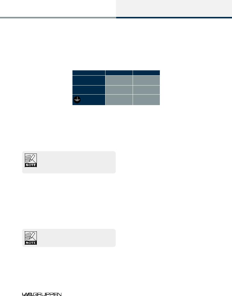
If the mains plug (AC plug) fitted to the mains cable (AC cord) is not appropriate for your country, it can be removed and a locally-sourced one fitted instead, observing the color coding in the table below:
powerCON Pin |
230 V Version |
115 V Version |
L |
Brown |
Black |
N |
Blue |
White |
|
Green/Yellow |
Green |
Table 3-1: AC Plug Configuration
 If you are not 100% confident of your competence to replace the mains plug (AC plug), the task should be carried out by qualified personnel.
Once a suitable AC power supply is connected, the device can be turned on using the front panel power button. When the device is turned on, the power button LED changes from red (Standby) to green (Active).
In-rush current is controlled and limited during the soft-start sequence. This enables multiple PLMs on the same AC mains circuit to be turned on simultaneously.
3.5Grounding
Analog inputs feature Iso-Float™ ground isolation, a technology which combines the benefits of transformercoupled isolation with the advantages of clean, direct-coupled inputs.
The audio converters are galvanically isolated, and not connected to the main ground. High-speed transformers and opto-isolators create a barrier between the device and the outside electrical environment.
The Iso-Float feature is activated by default, but may be disabled via the Lake Controller software, or via the front panel menu.
Use correctly-shielded balanced audio input connections to minimise hum and interference. Please refer to section 8.2.4 for further information.
 NEVER disconnect the earth (ground) pin on the mains cable (AC power cord).
PLM Series Operation Manual Rev 1.3.0 |
7 |

Product Overview
4. Product Overview
This chapter provides an overview of key features and functionality. For further information please see chapters 5 to 10 of this Operation Manual.
4.1Front Panel Overview
Figure 4-1: Front Panel Overview
The front panel controls are clustered around a daylight readable LCD  , allowing adjustment and monitoring of the majority parameters and meters. The two clusters of controls on either side of the LCD include five dedicated function buttons


 , eight dynamic function buttons with embedded LEDs
 and a rotary data encoder
  .
.
 Handles
Two sturdy cast aluminium handles are integrated into the front panel. The handles should be used when carrying the device, and when fitting into or removing from a rack. Ensure that any door or removable rack front cover has sufficient depth to clear the handles.
 Dust Filters
Two dust filters are fitted behind metal covers. To remove the covers, loosen the thumbscrews located behind the handles. Once detached, the dust filter elements can be removed for cleaning; please refer to section 9.2 for further information.
NEVER operate this device without the dust filters in place.
8 PLM Series Operation Manual Rev 1.3.0

Product Overview
 Display
The display illuminates when the device is on. The LCD, function buttons, and the rotary encoder provide real-time control and monitoring of most parameters. The LEDs embedded in the function buttons indicate available menu options, provide confirmation of Controller communication, and indicate various faults and warnings.
The brightness and contrast of the display and front panel LEDs can be adjusted via the front panel menu.
Please refer to chapter 7 for further details.
 Standby
PLM Series devices are powered on and to standby using the top-left button, or via the Lake Controller.
 Mute Enable
Select MUTE ENABLE to allow the dynamic function buttons to operate as mute controls for the Module inputs and power output channels. The MUTE ENABLE button flashes when the mode is selected; a subsequent press deselects this mode. If left activated, MUTE ENABLE mode will automatically disable two minutes after the last mute action.
 Meter
Meter
The METER button scrolls through various meter views including the default Home View, Module View, Temperature View and Input View. Pressing METER from Menu Mode returns the screen to Meter Mode with the Home View displayed. Please refer to section 7.5 for further details.
 Menu
Menu
After pressing the MENU button, the LCD will display the top level menu. In Menu Mode the dynamic function buttons enable access to various information and functionality. Please refer to section 7.6 for further details.
 Dynamic Function Buttons with LEDs (Left of LCD)
The function of these buttons change according to the currently selected view or menu.
In Menu Mode they are used for menu navigation and for parameter selection
In Meter Mode they provide Module input mute/unmute functionality in conjunction MUTE ENABLE
PLM Series Operation Manual Rev 1.3.0 |
9 |

Product Overview
The LED in the top button provides Frame fault and warning indications. The middle two buttons provide Module input mute functionality, mute indication and faults and warning indications relating to the PLM inputs. The bottom button is used only in Menu Mode or to lock the front panel buttons.
Please refer to chapter 7 for further details.
 Dynamic Function Buttons with LEDs (Right of LCD)
The function of these buttons change according to the currently selected view or menu.
In Menu Mode they are used for menu navigation and for parameter selection
In Meter Mode they provide PLM output mute/unmute functionality in conjunction MUTE ENABLE
All LEDs provides mute, clip, fault and warning indications for the PLM power outputs channels.
Please refer to chapter 7 for further details.
 Communication LED
The high-intensity white LED illuminates white to indicate that the Module/Frame is selected in the Lake Controller; it flashes white to indicate communication with the Lake Controller.
The brightness of the LCD and communications LED can be adjusted in the Frame page of the Main Menu on the front panel.
 Rotary Encoder
The rotary encoder is used to modify various parameters (e.g. input level) via the menu. When a menu item is selected that permits adjustment of parameter values, the ring around the rotary encoder illuminates. In Home View the encoder can be used to scroll through the Meter Views.
 Exit
Exit
The EXIT button is used primarily while navigating the menu system in Menu Mode; pressing EXIT will return the menu up one level. In Meter Mode, pressing EXIT returns the metering display to the default Home View.
10 PLM Series Operation Manual Rev 1.3.0

Product Overview
4.2Back Panel Overview
Figure 4-2: Back Panel Layout Options for a 4-channel PLM
Figure 4-3: Back Panel Layout Options for a 2-channel PLM
PLM Series Operation Manual Rev 1.3.0 11

Product Overview
4.2.1Input and Link Connectors
 Analog Inputs
Analog inputs are available on two standard XLR3F latching connectors. The inputs are electronically balanced and feature Lake Iso-Float circuitry. The impedance is 20 kohms, and the inputs can accept a maximum input level of +26 dBu.
 Analog Links
Two latching XLR3M connectors are fitted adjacent to the analog input connectors. These are paralleled to the input connectors to provide an unprocessed analog loop-through to feed additional PLM Series units, or other equipment.
 AES3 Inputs
A latching XLR3F connector is provided which accepts an AES3 digital audio signal. Input impedance is 110 ohms, please ensure that 110 ohm digital audio cables are used; standard XLR microphone cables are rarely suitable for reliable digital audio transmission.
AES3 is a stereo digital format, and therefore both PLM inputs are fed via a single connector. Selection of the analog or digital inputs is made via the front panel display or control software.
 AES3 Link
A latching XLR3M connector is fitted adjacent to the AES3 input connector. This is paralleled to the input connector to provide an unprocessed AES3 loop-thru to feed further PLMs, or other equipment. An AES3 110 ohm termination load is enabled by default when the PLM is the last unit connected within an AES3 daisy-chained system. The termination may be disabled, if desired, via the front panel menu and within the Lake Controller software.
4.2.2Output Connectors
The PLM is available with a choice of connectors for power outputs: binding posts or Neutrik speakON®. Both connection methods allow for Bridge Mode operation, which is activated from the Lake Controller software. Please refer to the Lake Controller Operation Manual and section 8.1.1 of this Operation Manual for further information on Bridge Mode.
12 PLM Series Operation Manual Rev 1.3.0

Product Overview
 Binding Posts
In this version, the power outputs for loudspeaker connection are available on four separate pairs of fully enclosed binding posts. Bridge Mode can be enabled via the Lake Controller software, please refer to the Lake Controller Operation Manual for further information.
Channel configuration for the binding posts is dependent on the PLM model, please refer to section 8.1.3 of this Operation Manual for standard and Bridge Mode wiring.
 speakON Connectors
The speakON connector configuration differs on 2-channel and 4-channel PLM models.
On 4-channel models, the power outputs are simultaneously available on a single 8-pole speakON connector, and on two 4-pole speakON connectors. The two 4-pole connectors carry the outputs of channels 1 & 2 and 3 & 4 respectively.
On 2-channel PLM models the two power output channels are available simultaneously on two 4-pole speakON connectors. Both connectors carry both channels. The second connector offers the channels in reverse order.
Bridge Mode can be enabled via the Lake Controller software, please refer to the Lake Controller Operation Manual and to section 8.1.2 of this Operation Manual for further details on standard and Bridge Mode wiring for speakON connectors.
4.2.3Ethernet and Power Connectors
 Primary Network Connector
The primary Neutrik RJ45 etherCON® connection provides integration into an Ethernet control network which may include other Lake Processors and the Lake Controller software. Network connection permits full control of all functions along with real-time metering from a remote position. This device supports the Dante audio networking protocol, which allows transmission of multichannel, high-definition digital audio over the same Ethernet connection.
Use the primary connector when using a star network topology, consisting of individual Cat-5e connections between the devices and an Ethernet switch. Alternatively this connection can be used to daisy chain directly to another Lake Processor. The daisy chain topology should not be used with Dante.
For a technical reference of the Ethernet Port, please refer to section 8.4 . Additional information is also available in the Lake Network Configuration Guide.
PLM Series Operation Manual Rev 1.3.0 13

Product Overview
The Ethernet ports operate at the Ethernet data rate of 100 Mbps, and allow straight or crossed network cables. Two LEDs above each port indicate valid network connection (LINK) and network activity (ACT).
 Secondary Connector
The secondary network connector can be used to daisy-chain multiple LM & PLM Series and legacy Dolby and Lake devices. Alternatively, a Dante dual-network topology can be created by connecting all secondary network connectors to a separate Ethernet switch, ensuring full redundancy in the event of a network component failure.
Additional processor configuration is required for a dual redundant network setup. See the Lake Controller Operation Manual for further details.
For a technical reference of the Ethernet Port, please refer to section 8.4 . Additional information is also available in the Lake Network Configuration Guide.
When connecting multiple devices to an Ethernet network, care must be taken NOT to create a closed loop which causes network malfunction.
 Mains Power Connector
The mains power AC input is via a Neutrik powerCON connector, rated at 32 A.
The power supply must be connected to AC mains using a power cable with a correctly wired plug for the country of operation.
14 PLM Series Operation Manual Rev 1.3.0
Operation and Performance
5. Operation and Performance
This chapter provides comprehensive information on PLM Series connection, setup, operation and performance. The detailed information included here is essential to realizing the full functionality of the PLM Series devices.
5.1Operation Precautions
Make sure that the Standby button on the PLM’s front panel is either unlit (OFF), or red (STANDBY), before making any input or output connections.
 Ensure the AC voltage matches that printed on the label adjacent to the AC mains connector.
Ensure no input signal is present when powering on the PLM to reduce the risk of any inadvertent bursts of high level audio.
5.2Power Output Performance
The PLM uses Lab.gruppen’s patented Class TD technology in the output stages, which couples the efficiency of Class D topologies to the sonic purity of Class B designs.
The primary benefit is that Lab.gruppen’s Class TD works perfectly under all load conditions. The output maintains its flat frequency response even into complex loads with very low nominal impedances. Reliability is very high, and there is no interference with nearby RF equipment. Superior efficiency allows greater power density while minimizing cooling requirements, yet sound quality matches that of the best Class B designs.
5.2.1Symmetrical Power
The PLM models can deliver power as shown in Table 5-1 when all channels are driven equally.
Load Impedance (ohms) |
2.0 |
2.7 |
4 |
8 |
16 |
|
PLM 10000Q |
2350 |
2700 |
2300 |
1300 |
660 |
|
Max. Output power (Watts) |
||||||
|
|
|
|
|
||
PLM 14000 |
7000 |
6000 |
4300 |
2300 |
1150 |
|
Max. Output power (Watts) |
||||||
|
|
|
|
|
||
PLM 20000Q |
4800 |
5000 |
4440 |
2300 |
1150 |
|
Max. Output power (Watts) |
||||||
|
|
|
|
|
Table 5-1: Symmetrical Load Power Ratings
PLM Series Operation Manual Rev 1.3.0 15

Operation and Performance
5.2.2Asymmetrical Power
The PLM models can deliver power as shown in Table 5-2 when every other channel is driven 3 dB lower than the other. This can occur when the load on the individual power output channels within the amplifier contain different frequency ranges.
Load Impedance (ohms) |
2.0 |
2.7 |
4 |
8 |
16 |
|
PLM 10000Q |
2350 |
2900 |
2400 |
1300 |
660 |
|
Max. Output power (Watts) |
||||||
|
|
|
|
|
||
PLM 14000 |
7500 |
6300 |
4400 |
2300 |
1150 |
|
Max. Output power (Watts) |
||||||
|
|
|
|
|
||
PLM 20000Q |
5000 |
5550 |
4500 |
2300 |
1150 |
|
Max. Output power (Watts) |
||||||
|
|
|
|
|
Table 5-2: Asymmetrical Load Power Ratings
5.2.3Power Over Time
Power ratings given above are applicable for PLMs running at these levels for a period of 60 minutes. Due to thermal considerations in the power supply and elsewhere, it is possible to draw higher power levels for a shorter period of time. The graph below illustrates, for the example PLM 10000Q, how the rated power figures are derived and the higher short-term capability.
Peak output voltage at “max power burst”
Figure 5-1: Power Rating Levels OverTime (PLM 10000Q)
Power ratings are based on a duty cycle of 25 ms full power every 400 ms. Between bursts, a lower signal level applies, such that the continuous average power is 1/8th of the rated power.
16 PLM Series Operation Manual Rev 1.3.0

Operation and Performance
In reality, when some channels are delivering less than maximum rated power, energy reserves in the PSU are available to permit other channels to deliver more power. The graph shows the peak output voltage over time for a continuous sine wave is applied.
If all four channels are driven with the same signal into the same impedance (solid red line), then the rail voltage (dotted red line) will drop faster than when two channels are delivering maximum power (solid blue line) and two channels are delivering half-power (solid orange line). This is termed asymmetric loading; the rail voltage for this is indicated by the dotted blue line.
It can be seen that higher power output is available for 25 ms bursts with asymmetric loading.
5.3Amplifier and Load Protection Systems
The PLM is equipped with a comprehensive set of protection circuits. If operating conditions become sufficiently extreme that any of these circuits become active, indication is provided by LEDs in one or more soft function buttons 5-8, together with adjacent warning text. In addition to this, notification is also presented within the Lake Controller software and within system log files.
5.3.1Inter-Sample Voltage Peak Limiter (ISVPL)
The ISVPL is a high quality voltage limiter that can deliver seamless limitation to any desired level. Its ensures that the voltage at the output terminals never exceeds the defined threshold.
It operates on these principles:
The signal is delayed slightly to allow the ISVPL to look-ahead and reduce the gain before voltage in excess of the threshold can appear at the output. This results in zero voltage overshoot at the output with a rounded limitation up to the threshold.
The amplitude of the output signal between digital samples is predicted which permits the ISVPL to respond to analog peaks that may occur at the digital to analog converter.
The release time of gain reduction is adaptive depending on the dynamics of the signal.
It is possible to select different ISVPL profiles for limiting optimization for a specific frequency band and personal preference. The profiles are divided into two categories, with one category optimized for low distortion and the other focusing on producing high sound pressure level (SPL). Within each category there are profiles optimized for the different frequency bands.
5.3.1.1Low Distortion Profiles
Universal – The universal profile is a soft limiter that can be used for all frequencies and is conservative in its action upon VCL and CPL.
Sub/LF – The Sub/LF profile is tuned for frequency bands below 600Hz. It has longer attack and release times and is less conservative when it comes to acting upon VCL and CPL.
PLM Series Operation Manual Rev 1.3.0 17

Operation and Performance
5.3.1.2 High SPL Profiles
High SPL profiles do not use the adaptive release time feature. High SPL profiles optimized for high frequencies use less of the look-ahead delay peak-rounding feature; this feature is used most in the Sub profile and least the HF profile.
Sub - The Sub profile is optimized for frequencies between 20 - 200 Hz
LF - The LF profile is optimized for frequencies between 20 - 1200 Hz
MF - The MF profile is optimized for frequencies between 300 - 6000 Hz
HF - The HF profile is optimized for frequencies above 1 kHz
Table 5-3 shows the theoretical maximum output power for a given load impedance and ISVPL setting.
An ISVPL-to-load calculator that will assist in generating the appropriate ISVPL setting for a desired power load is available at www.labgruppen.com/plm
MAX. SINEWAVE BURST POWER (Watts)
Load Impedance (ohms) |
2 |
2.67 |
4 |
8 |
16 |
ISVPL SETTING (V peak) |
|
|
|
|
|
194 |
9409 |
7048 |
4705 |
2352 |
1176 |
193 |
9312 |
6984 |
4656 |
2328 |
1164 |
181 |
8190 |
6143 |
4095 |
2048 |
1024 |
167 |
6972 |
5229 |
3486 |
1743 |
872 |
153 |
5852 |
4389 |
2926 |
1463 |
732 |
121 |
3660 |
2745 |
1830 |
915 |
458 |
101 |
2550 |
1913 |
1275 |
638 |
319 |
83 |
1722 |
1292 |
861 |
431 |
215 |
70 |
1225 |
919 |
613 |
306 |
153 |
56 |
784 |
588 |
392 |
196 |
98 |
47 |
552 |
414 |
276 |
138 |
69 |
38 |
361 |
271 |
181 |
90 |
45 |
17.8 |
79 |
59 |
40 |
20 |
10 |
These ratings shown in Table 5-3 are limited by the CPL (Current Peak Limiter) functions, not by ISVPL settings, due to power output channel current capacity.
18 PLM Series Operation Manual Rev 1.3.0

Operation and Performance
The ISVPL threshold may be set at any level between 17.8 V and 600 V via the PLM’s menu system. For further details, please refer to section 7.11.2.5 of this manual, and also to the PLM Series chapter in the Lake Controller User Manual.
PLM devices that have a smaller peak output voltage can still set the ISVPL threshold up to 600 V. When a threshold is set above the maximum capability of a power output channel, the maximum ISVPL for that product will be automatically set. Therefore, the ISVPL threshold can be in at the Module for the speaker’s maximum capability, and the Module file remains cross-compatible with all PLM Series devices.
5.3.2Current Peak Limiter (CPL)
The output Current Peak Limiter (CPL) ensures that the power output section will not be damaged by forcing it to deliver current levels at the outputs that exceed the maximum current ratings of the output transistors. The CPL keeps the output transistors within their Safe Operating Area (SOA). The CPL is non-adjustable.
CPL activity is indicated on the power output channel LED (embedded in the associated output channel’s function button to the right of the LCD). Activity on an affected channel results in a flashing red indication together with a CURRENT CLIP warning message displayed on the screen adjacent to the LED. A warning is also displayed on the controlling PC via the network.
This condition indicates an attempt to draw excessive current at the output. The output is attenuated until the output current falls below the maximum current rating. Limiting is performed by the ISVPL limiter in conjunction with the selected ISVPL profile. Please refer to the Technical Specifications in chapter 11 for further details regarding ratings.
If excessive current is indicated, check the output cables and examine the loudspeaker. If impedance appears normal, you may rectify the condition by altering the ISVPL settings or lowering input levels. CPL indication can be triggered by excessively low output impedance, possibly the result of too many loudspeaker cabinets connected in parallel.
5.3.3Power Average Limiter (PAL)
5.3.3.1 PLM 10000Q and PLM 14000
The Power Average Limiter (PAL) controls the AC current into the power supply. Power consumption is limited to the rated design parameters of the power supply, ensuring that the PSU will never be overloaded. Also, high-power products such as those in the PLM Series can potentially draw more current (with output devices still within safe operating areas) than is allowed by the external mains breaker.
The PAL protection feature can help prevent the supply’s external breaker from tripping within time intervals of less than three minutes. For longer time intervals, it is the responsibility of the user to ensure that the average level of the audio is within limits that ensure that the breaker doesn’t trip.
PLM Series Operation Manual Rev 1.3.0 19

Operation and Performance
PAL activity is indicated by the LED within the first soft button adjacent to the display flashing red, together with a PAL ACTIVE warning message displayed on the screen. A warning is also displayed on the Lake Controller software.
5.3.3.2 PLM 20000Q
The Power Average Limiter Active warning (PAL Active) will be displayed when the power supply’s maximum rated design parameters are reached. When this warning is displayed, gain limiting is being applied to the signal and the ISVPL threshold is lowered accordingly.
5.3.4Breaker Emulation Limiter (BEL™)
The Breaker Emulation Limiter feature is present only in the PLM 20000Q. The PLM 20000Q is a powerful device that can draw a considerable amount of current from the mains supply. The BEL models the temperature in the external breaker and limits the mains current to prevent it from tripping. The BEL can be configured with both a breaker profile and a current value. The current value can be set from 5 to 32 Arms.
There are three different profiles available for selection:
Conservative - The conservative profile allows no momentary current above the configured threshold.
Fast - The fast profile models the time constant of the trip-curve corresponding to a fast breaker. It momentarily allows current above the threshold to pass for a short time, leading to an increased modeled temperature. For the limiter to disengage, the current must reduce below the threshold to enable the breaker to cool down.
Universal - The universal profile models the time constant of the tripp-curve corresponding to a slow breaker. It momentarily allows current above the threshold for a longer time, leading to an increased modeled temperature. For the limiter to disengage the current has to reduce below the configured current for the breaker to cool down.
The BEL can be configured via the PLM front panel and via the Lake Controller.
5.3.5Under Voltage Limiter (UVL™)
The PLM 20000Q is equipped with an under voltage limiter. With mulitple powerful devices on a mains distribution line, heavy current loads risk the reduction of voltage below that required for devices to function. The PLM 20000Q’s UVL reduces the mains current draw when voltage drop below 80 V. The amount of reduction applied increases as mains voltage drops towards 65 V, then at 65 V the power supply is shut down. The mains supply is continually monitored and when sufficient voltage returns the power supply automatically restarts.
20 PLM Series Operation Manual Rev 1.3.0

Operation and Performance
5.3.6Current Average Limiter (CAL™)
The Current Average Limiter (CAL) monitors the RMS current drawn from each power output channel to ensure that the power output stages are not overloaded. When activated, it regulates the current to a safe level to protect the channel. The CAL should not be activated in normal usage, but if it is, its operation is indicated by an active LED and the message CAL ACTIVE. Further indication is given within the Lake Controller software.
5.3.7Voltage Clip Limiter (VCL)
If current draw from the PLM’s power supply is too high, the PSU’s regulation capability may be exceeded and the internal voltage rails may drop and cause clipping. If this occurs the VCL acts rapidly to prevent clipping on the subsequent peaks. Limiting is performed by the ISVPL limiter in conjunction with the selected ISVPL profile. Indication of this condition is shown on the output LEDs.
5.3.8Temperature Protection
5.3.8.1 Overview
PLM Series devices are equipped with a sophisticated temperature sensing system that provides protection from overheating which may occur as a result of inadequate ventilation or excessive power output.
Thermal measurements are made at several points within each power output channel along with measurements in the power supply and DSP areas. If temperature in any area reaches a critical level then a warning is displayed and gain reduction is applied. If the temperature continues to increase and reaches a dangerous level then a fault is displayed and audio is muted. Each power output channel, the power supply and DSP area have separate indications.
For all temperature faults, temperature monitoring will continue at 0.5 second intervals, with the output remaining muted. When the area has cooled below the dangerous threshold, the fault condition is cleared and audio is restored.
5.3.8.2 Power Output Channels
A power output channel temperature warning or fault is indicated in one of the front panels LEDs (in the right-hand soft function buttons).
A warning is indicated by a static yellow LED and adjacent warning message: TEMP WARN:CH
A fault is indicated with a static red LED and adjacent warning message: TEMP FLT:CH
An event report is sent to the Lake Controller software for both the warning and the fault. If a temperature fault condition arises on a power channel, the output of that channel will be muted.
PLM Series Operation Manual Rev 1.3.0 21

Operation and Performance
5.3.8.3 Power Supply / DSP
A power supply (PSU) or DSP temperature warning or fault is indicated by the LED in the top-left function button.
A warning is indicated by a static yellow LED and adjacent warning message: TEMP WARN:PSU (or TEMP WARN:DSP)
A fault is indicated with a static red LED and adjacent warning message: TEMP FLT:PSU (or TEMP FLT:DSP)
An event report is sent to the Lake Controller software for both the warning and the fault. If a temperature fault condition arises in the power supply the output of all channels will be muted. If a temperature fault condition arises in DSP area, audio will not be muted but continued operation is not recommended.
5.3.8.4 PLM 20000Q
For the PLM 20000Q a temperature dependant limiting feature is also present. At temperatures above the critical warning level and below the dangerous fault level, the ISVPL threshold is slowly reduced to decrease the output power and cool down the device. This enables the device to continue to pass audio, although with a reduced amplitude, in extreme conditions. If reducing the ISVPL threshold does not cool down the device a temp fault will still be issued when the dangerous temperature level is reached.
5.3.9DC Protection
DC protection is implemented on each power output to prevent damage to connected loudspeakers or any PLM components. DC present at the output will cause the PLM’s power output module breaker to blow. In this instance a red LED will illuminate and NEEDS SERVICE will display on the LCD.
The power output channel modules are independent of the input voltage. Both 115 and 230 V models have amp channel fuses. This is not a user-servicable fault condition and the unit should be returned for repair.
5.3.10 VHF Protection
The PLM includes protection circuits that detect Very High Frequency (VHF) content in the input signal. The detection is frequency-dependent, initiated from 10 kHz upwards. If VHF signals are detected above the threshold, the output will mute for approximately 6 seconds before a further measurement is taken. When continuous VHF signal stops, the output unmutes and the amplifier returns to normal operation.
This protection system recognizes that continuous VHF signals at high levels do not appear in speech or music. Any such content can therefore be considered as a fault condition. VHF protection is essential to avoid damage to HF drivers.
22 PLM Series Operation Manual Rev 1.3.0

Operation and Performance
VHF protection is dependent on a combination of output power level and frequency. Figure 5-2 shows a decreasing power threshold, from approximately 10 kHz upwards, which illustrates increasing sensitivity of the protection system with frequency. When continuous output power above the threshold line is detected, VHF protection becomes active.
Figure 5-2: VHF Protection Frequency Sensitivity
The attack time of the VHF protection circuitry also changes with frequency, becoming shorter at higher frequencies. This is shown in Figure 5-3.
Figure 5-3: VHF Protection AttackTime Variations
The VHF protection circuit is NOT a limiter and does not alter the PLM’s frequency response. It is implemented solely to detect continuous VHF content. HF content of normal music or speech signals at peak levels will be passed in full.
Operation of the VHF protection circuits is indicated by one (or more) of the output channel LEDs (in the right-hand soft function buttons) showing steady red. The adjacent fault message will show VHF FAULT. It is also reported as a fault via the control network.
PLM Series Operation Manual Rev 1.3.0 23

Operation and Performance
5.3.11 Short Circuit Protection
A low impedance or short circuit at the power output terminals is detected when the output current is high (Current Peak Limiter is active) and, simultaneously, the peak output voltage is below a predetermined threshold (42 V with the PLM 10000Q, for example). When this situation occurs, the output stage is muted to protect it from damage. Operation of the short circuit protection system is indicated by an output channel LED (in the right-hand soft function buttons) showing steady red. The adjacent fault message will show SHORT CIRCUIT. It is also reported as a fault via the control network to the Lake Controller software. The presence of a short circuit (or low impedance) is re-tested every six seconds, and the output remains muted until the fault clears.
5.4Power Supply
The R.SMPS (Regulated Switch Mode Power Supply) is designed to keep supply voltage rails at optimum levels even when the mains voltage drops. Mains voltages can drop as much as 20% below nominal before there is any effect on rail voltages. Thus the R.SMPS can deliver full rail voltage to the output stage at all times, allowing the PLM to exhibit consistent transient response and a clean LF response.
The PLM 20000Q is also equipped with a universal power supply with power factor correction (PFC). The device can take any mains voltage, from 65 V to 265 V, allowing it to function worldwide in many different configurations. The PFC reduces current peaks on the lines and reduces the requirements placed on the mains distribution system. The PLM 20000Q has an unparalleled power factor extremely close to one.
5.4.1Low Inrush Current
High power amplifiers with inadequate inrush current limiting can draw considerable current from the mains at turn-on, sometimes tripping a fast-acting mains breaker. The PLM, however, has very low inrush current (the capacitors charge slowly and in a controlled manner) to prevent tripping of breakers.
Several PLMs can, under normal conditions, be powered up simultaneously. If you do experience problems powering up multiple PLMs simultaneously, they must either be turned on manually in an ordered manner, or sequenced remotely using the Lake Controller software’s Global Control feature. Alternatively, the capacity of the mains supply should be increased.
If insufficient power is available to allow simultaneous power-up, then there is probably insufficient capacity for full power output during operation. It is recommended that additional capacity is added to the mains power distribution system.
24 PLM Series Operation Manual Rev 1.3.0
Loading...