


LM 44
Table of contents
 Loading...
Operation Manual
Lake® LM Series
Digital Audio Processors
Rev 1.2.8
Item: OM-LM
Important Safety Instructions
1. Important Safety Instructions
Before using the device, be sure to carefully read the Safety Instruc tions. Keep this document with the device at all times.
1.1 Important Safety Instructions
1. Read these instructions.
2. Keep these instructions.
3. Heed all warnings.
4. Follow all instructions.
5. Do not use this apparatus near water.
6. Clean only with a dry cloth.
7. Do not block any ventilation openings. Install in accordance
with the manufacturer’s instructions.
8. Do not install near any heat sources such as radiators, heat
registers, stoves, or other apparatus (including ampliers)
that produce heat.
9. Do not defeat the safety purpose of the polarized or
grounding-type plug. A polarized plug has two blades with
one wider than the other. A grounding-type plug has two
blades and a third grounding prong. The wide blade or
the third prong is provided for your safety. If the provided
plug does not t into your outlet, consult an electrician for
replacement of the obsolete outlet.
10. Protect the power cord from being walked on or pinched,
particularly at plugs, convenience receptacles, and the point
where they exit from the apparatus.
11. Only use attachments/accessories specied by the
manufacturer.
12. Use only with a cart, stand, tripod, bracket, or table specied
by the manufacturer, or sold with the apparatus. When a
cart is used, use caution when moving the car t/apparatus
combination to avoid injury from tip-over.
13. Unplug this apparatus during lightning storms or when
unused for long periods of time.
14. Refer all servicing to qualied service personnel. Servicing
is required when the apparatus has been damaged in any
way, such as power-supply cord or plug is damaged, liquid
has been spilled or objects have fallen into the apparatus, the
apparatus has been exposed to rain or moisture, does not
operate normally, or has been dropped.
15. Use the mains plug to disconnect the apparatus from the
mains.
16. WARNING: To reduce the risk of re of electric shock, do not
expose this apparatus to rain or moisture.
17. Do not expose this equipment to dripping or splashing and
ensure that no objects lled with liquids, such as vases, are
placed on the equipment.
18. The mains plug of the power supply cord shall remain readily
operable.
19. Do not connect the unit’s output to any other voltage source,
such as battery, mains source, or power supply, regardless
of whether the unit is turned on or off.
20. Do not remove the top (or bottom) cover. Removal of the
cover will expose hazardous voltages. There are no user
serviceable par ts inside and removal may void the warranty.
21. An experienced user shall always supervise this professional
audio equipment, especially if inexperienced adults or
minors are using the equipment.
22. The US National Differences clause 16.3 requires that
network cables must be ame rated V W-1.
To prevent electric shock do not remove top or bottom covers.
No user serviceable parts inside, refer servicing to qualied
service personnel.
À prévenir le choc électrique n’enlevez pas les couvercles. Il n’y a
pas des parties serviceable à l’intérieur, tous reparations doit etre
faire par personnel qualié seulment.
To completely disconnect this equipment from the AC mains,
disconnect the power supply cord plug from the AC receptacle.
The mains plug of the power supply cord shall remain readily
operable.
Pour démonter complètement l’équipement de l’alimentation
générale, démonter le câble d’alimentation de son réceptacle. La
prise d’alimentation restera aisément fonctionnelle.
1.2 Standards
This equipment conforms to the requirements of the EMC Directive 2004/108/EC
and the requirements of the Low Voltage
Directive 2006/95/EC.
Standards applied: EMC Emission
EN55103 -1, E3
EMC Immunity EN55103-2, E3, with S/N
below 1% at normal operation level.
Electrical Safety EN60 06 5, Class I
This equipment is tested and listed according to the U.S. safety standard ANSI/ UL
60065 and Canadian safety standard CSA
C22.2 NO. 60065. Intertek made the tests
and they are a Nationally Recognized Testing Laboratory (NRTL).
1.3 Explanation of Graphical Symbols
The lightning bolt triangle is used to alert the user to
the presence of un -insulated “dangerous voltages”
within the unit’s chassis that may be of sufcient
magnitude to constitute a risk of electric shock to
humans.
The exclamation point triangle is used to alert the
user to presence of important operating and service
instructions in the literature accompanying the
product.
Lake LM Series Operation Manual Rev 1.2.8
i
Important Safety Instructions
1.4 WARNING
To reduce risk of re or electric shock, do not expose this apparatus to rain or moisture.
Pour réduire les risques de blessure ou le choc électrique, n’exposez pas l’appareil à la pluie ou à l’ humidité.
Do not expose this system/apparatus to dripping or splashing and ensure that no objects lled with liquids, such
as vases, are placed on the apparatus.
L’appareil ne doit pas être exposé à des egouttements d’eau ou des éclaboussures et de plus qu’aucun objet
rempli de liquide tel que des vases ne doit pas être placé sur l’appareil.
This apparatus must be connected to a mains socket outlet with a protective earthing connection.
Cet appareil doi t être raccordé á une prise de courant qui est branchée à la terre.
The mains plug is used as a disconnect device and shall remain readily operable.
Lorsque la prise du réseau d’alimentation est utilisés comme dispositif de déconnexion, ce dispositif doit
demeuré aisément accessible.
1.5 CAUTION
To reduce the risk of re or electric shock, do not remove screws. No user-ser viceable parts inside.
Refer servicing to qualied service personnel.
Pour réduire le risque d’incendie ou de choc électrique, ne pas retirer les vis. Aucune pièce réparable par
l’utilisateur. Coner l’entretien àpersonnel qualié.
1.6 FCC Compliance Notice (Radio Interference)
A sample of this product has been tested and complies with the limits for the European Electro Magnetic
Compatibility (EMC) directive. This equipment has also been tested and found to comply with the limits for a
Class B digital device, pursuant to Part 15 of the FCC Rules. These limits are designed to provide reasonable
protection against harmful interference from electrical equipment. This product uses radio frequency energy
and if not used or installed in accordance with these operating instructions, may cause interference to other
equipment, such as radio receivers.
However, there is no guarantee that interference will not occur in a particular installation. If this equipment
does cause harmful interference to radio or television reception, which can be determined by turning the
equipment on and off, the user is encouraged to try to correct the interference by one or more of the
following measures:
▸ Reorient or relocate the antenna.
▸ Increase the separation between the equipment and receiver.
▸ Connect the equipment to an outlet on a circuit different from that to which the receiver is connected.
ii
Lake LM Series Operation Manual Rev 1.2.8

Important Safety Instructions
▸ Check if the affected unit complies with the EMC limits for immunity, (CE-labeled). If not, address the
problem with the manufacturer or supplier. All electrical products sold in the EC must be approved for
immunity against electromagnetic elds, high voltage ashes, and radio interference.
▸ Consult the dealer or an experienced radio/ T V technician for help.
1.7 User Responsibility
1.7.1 Mains Connection Grounding
Your apparatus must be connected to a grounded socket outlet.
1.7.2 Maintenance
For safe and reliable operation, the dust lter on the right-hand side air intake should be removed and
cleaned regularly to ensure maximum airow through the device.
If the dust lter is not maintained there will be safety risks; for example, high internal temperatures
could ignite the dust and start a re. There is also a risk that the unit will malfunction since it is dependent
on constant airow from left to right. If the dust lter is not clean and the unit malfunctions, any resulting
problems will not be covered by the warranty.
Lake LM Series Operation Manual Rev 1.2.8
iii

Table of Contents
1. Important Safety Instructions ................................................................................................................i
1.1 Important Safety Instructions ............................................................................................................... i
1.2 Standards ..............................................................................................................................................i
1.3 Explanation of Graphical Symbols ......................................................................................................... i
1.4 WARNING ............................................................................................................................................ ii
1.5 CAUTION ............................................................................................................................................. ii
1.6 FCC Compliance Notice (Radio Interference) ....................................................................................... ii
1.7 User Responsibility ..............................................................................................................................iii
2. Welcome ...................................................................................................................................................1
2.1 Introduction .........................................................................................................................................1
2.2 Main Features ......................................................................................................................................1
2.3 Additional Documentation ....................................................................................................................2
3. Installation ................................................................................................................................................ 3
3.1 Unpacking ............................................................................................................................................3
3.2 Mounting ..............................................................................................................................................3
3.3 Cooling .................................................................................................................................................3
3.4 Operating Voltage ................................................................................................................................4
3.5 Grounding ............................................................................................................................................. 4
4. Product Overview .................................................................................................................................... 5
4.1 Front Panel Overview ........................................................................................................................... 5
4.2 Back Panel Overview ........................................................................................................................... 8
5. Signal Flow and Lake Processing ........................................................................................................ 11
5.1 Signal Flow ........................................................................................................................................ 11
5.2 Lake Processing and Control .............................................................................................................. 13
5.3 Modules and Frames ........................................................................................................................ 13
5.4 Loudspeaker Processor (Contour Mode) Overview ...........................................................................14
5.5 System Equalizer (Mesa Mode) Overview ......................................................................................... 14
5.6 Switching between Contour and Mesa Mode ...................................................................................14
5.7 Files and Presets ................................................................................................................................ 15
6. Front Panel Interface ............................................................................................................................. 16
6.1 Overview ............................................................................................................................................ 16
6.2 Front Panel Key Lock .......................................................................................................................... 17
6.3 Power Button .................................................................................................................................. 17
6.4 Meter Button ..................................................................................................................................... 18
6.5 Menu Button ...................................................................................................................................... 18
6.6 Exit Button
6.7 Dynamic Buttons, Controls and LEDs ................................................................................................ 18
6.8 Module I/O Mute Buttons and LED Meters ....................................................................................... 21
........................................................................................................................................18
iv
Lake LM Series Operation Manual Rev 1.2.8

6.9 Meter Mode ....................................................................................................................................... 23
6.10 Menu Mode .......................................................................................................................................25
7. Back Panel Interface .............................................................................................................................. 42
7.1 Analog Inputs and Outputs ................................................................................................................42
7.2 AES3 Digital I/O ................................................................................................................................44
7.3 RJ45 etherCON Network Connections ..............................................................................................45
7.4 GPIO Connection ...............................................................................................................................47
7.5 Universal Power Supply Connection .................................................................................................48
8. Appendix ................................................................................................................................................. 49
8.1 Faults and Warnings Overview ..........................................................................................................49
8.2 Maintenance ......................................................................................................................................50
8.3 Factory Default Settings.....................................................................................................................50
8.4 Glossary of Terms, Acronyms and Abbreviations ..............................................................................51
9. Application Guide ..................................................................................................................................54
9.1 Gain Structure ....................................................................................................................................54
9.2 Gain / Level Optimization ...................................................................................................................55
9.3 Digital Audio Connections ..................................................................................................................55
9.4 Digital Clock Conguration .................................................................................................................57
10. LM 26 Technical Specications ............................................................................................................61
11. LM 44 Technical Specications ............................................................................................................62
12. Warranty and Support ..........................................................................................................................63
12.1 General ..............................................................................................................................................63
12.2 International Warranties .....................................................................................................................63
12.3 Technical Assistance and Service ......................................................................................................63
12.4 Trademarks .........................................................................................................................................64
Lake LM Series Operation Manual Rev 1.2.8
v

Welcome
2. Welcome
2.1 Introduction
Thank you for choosing the Lake LM Series of Digital Audio Processors. We are condent that you will be
pleased with the performance, unique features, conguration exibility, reliability, and long-term durability
offered by this product.
For fast installation and use of this product, your welcome package includes a printed copy of the LM Series
Quick Start & Field Reference Guide which contains the information required to safely install the product and
place it in service. Control and editing features are accessible via the front panel interface or via the included
Lake Controller software.
It is recommend that the Quick Start & Field Reference Guide and all product documentation on the
included CD-ROM is reviewed to ensure familiarity with the various conguration and control options.
Thank you again for placing your condence in Lake products.
2.2 Main Features
The LM Series incorporates a number of sophisticated technologies to ensure the best possible performance and many years of reliable operation. The following section summarizes the benets of each feature;
additional information is available in the reference manuals.
2.2.1 Lake Processing and Controller
LM Series devices integrate seamlessly into the Lake Processing environment and are accessible via the
Lake Controller software. Processing modules offer precise settings for gain, delay, crossover settings,
equalization and limiting. Lake processing features incorporated in each module include Raised Cosine
Equalization™, linear phase crossovers, and LimiterMax™ loudspeaker protection. The Super Module feature
allows hardware processing modules in two or more separate devices to function as a single module in the
Lake Controller software. Please refer to the Lake Controller Operation Manual for further information.
2.2.2 Lake Analyzer Bridge
Lake Controller software provides integration with third-party real-time analyzers, providing simultaneous
measurement display and EQ adjustment via the Lake Controller.
The third-party measurement tools that can be integrated via the Analyzer Bridge include:
▸ Smaart Live Version 5.4
▸ Live-Capture Light / Live-Capture Pro
Lake LM Series Operation Manual Rev 1.2.8
1

Welcome
Smaart, distributed and supported by Rational Acoustics, provides real-time sound system measurement,
optimization and control. Smaart combines several powerful audio frequency measurement and analysis
tools.
Live-Capture, created by WaveCapture, offers easy-to-use software and measurement tools for sound
engineers, installers, consultants and designers. The Lake Analyzer Bridge in conjunction with Live-Capture
Light provides a completely free spectrum analyzer via your Lake Controller software interface.
2.2.3 Dante™ Audio Network
LM Series devices include Dante digital audio networking as standard. Utilizing the latest advances in
Ethernet technology, Dante offers simplied system conguration and extremely low latency while delivering very high quality uncompressed digital audio across the Lake network. The Zen™ automatic conguration
feature enables plug-and-play setup without third-party DHCP or DNS servers. Dante is compatible with
high-bandwidth networks, allowing large numbers of audio channels to be distributed alongside control and
analyzer data.
2.3 Additional Documentation
This document, the Lake LM Series Operation Manual, serves as the primary reference source for detailed
information on the installation and operation of LM Series devices. It also provides detailed information on
set-up and conguration using the front-panel interface.
If you intend to use the device as part of a networked system, or access features via the Lake Controller,
please refer to the various supporting documents which can be located via these methods:
▸ Start > Programs > Lake Controller > Documentation (after installing Lake Controller software)
▸ On the Installer CD-ROM or the downloaded software installer
▸ Online at: http://labgruppen.com/index.php/products/documentation/
2
Lake LM Series Operation Manual Rev 1.2.8

Installation
3. Installation
3.1 Unpacking
Carefully open the shipping carton and check for any damage to the device or the supplied accessories.
Every Lake product is tested and inspected before leaving the factory and should arrive in perfect condition.
If any damage is discovered, please notify the shipping company immediately. Only the consignee may
initiate a claim with the carrier or their insurers for damage incurred during shipping. Save the carton and
packing materials for the carrier’s inspection.
In addition to the Lake LM Series device, the shipping carton include the following items:
▸ Lake LM Series Quick Start & Field Reference Guide
▸ AC mains lead (IEC power cable) with locking connector
▸ AES break-out cable (8-in, 8-out)
▸ Ethernet Cable
▸ Software Installer and Documentation CD-ROM
Please keep the original carton and associated packaging to facilitate shipping of the device should the need
arise.
3.2 Mounting
Airow for cooling the device is from side to side (right-side intake to left-side fan). Please ensure there is
sufcient space each side of the unit to allow airow; the space provided by standard rack-rails should be
sufcient. This device has no top or bottom vents and therefore may be stacked directly on top of each
other.
Sufcient space should be available at the front of the rack to accommodate the handles, and at the rear to
accommodate connectors and cables; allowance must be made for cable or loom bends within a rack.
3.3 Cooling
The Lake LM Series devices use a forced-air cooling system, with airow from right to left. The dust lter
on the air intake (right-side) should be regularly cleaned, especially after exposure to dusty environments, to
ensure the maximum possible airow through the unit.
This device is designed to operate in situations where the ambient temperature is below 55
Automatic actions and warnings occur at following temperature thresholds:
▸ At 40oC (104oF) or less, the fan is OFF
Lake LM Series Operation Manual Rev 1.2.8
o
C (131oF).
3
Installation
▸ At more than 40oC (104oF) the fan is ON
▸ At 55oC (131oF) a temperature warning is indicated on the front panel as ‘TEMP WARNING’ and in the
Controller Event Log as ‘Temp warning: DSP area’.
▸ At 70oC (158oF) the device has exceeded the maximum normal operating temperature. This fault is
indicated on the front panel as ‘OVERTEMP’ and in the Controller Event Log as ‘Temp fault: DSP area’.
The Processor will NOT mute or shut down when the
temperature reaches or exceeds 70
sustained performance at this temperature cannot be
guaranteed.
o
C (158 oF), however,
3.4 Operating Voltage
The label above the IEC connector indicates the AC mains voltage range for which the device is approved.
LM Series devices utilize a universal power supply, and will operate within the range 70-265V~50-60Hz :
25W. If the plug on the IEC cable provided is not appropriate for your country, a locally-sourced IEC cable
with the appropriate molded plug should be used. A locking IEC cable is not necessary in order to power the
device, although is essential if locking functionality it required.
Once a suitable AC power supply is connected, the device can be turned on using the front panel power
button. When the device is turned on, the power button LED changes from red (Standby) to green (Active).
3.5 Grounding
Analog inputs and outputs feature Iso-Float™ ground isolation, a technology which combines the benets of
transformer-coupled isolation with the advantages of clean, direct-coupled inputs and outputs.
The audio converters are galvanically isolated, and not connected to the main ground. High-speed transformers and opto-isolators create a barrier between the device and the outside electrical environment.
The Iso-Float feature is activated by default, but
may be disabled via the Lake Controller software,
or via the front panel menu.
Use correctly-shielded balanced audio input connections to minimise hum and interference. Please refer to
section 7.1.5 for further information.
NEVER disconnect the earth (ground) pin on the mains cable (AC power cord).
4
Lake LM Series Operation Manual Rev 1.2.8

Product Overview
4. Product Overview
This chapter provides an overview of key features and functionality. For further information please see
chapters 5 to 9 of this Operation Manual.
4.1 Front Panel Overview
Figure 4-1: LM Series Front Panel Overview
The front panel controls are clustered around a daylight readable LCD , allowing adjustment and monitoring of the majority parameters and meters. The two clusters of controls on either side of the LCD include
three dedicated function buttons , six dynamic function buttons with embedded LEDs and a
rotary data encoder . To the right of these controls is a dynamic illuminated I/O divider along with input
and output mute buttons and level meters.
Handles
Two sturdy cast aluminium handles are integrated into the front panel. The handles should be used when
carrying the device, and when tting into or removing from a rack. Ensure that any door or removable rack
front cover has sufcient depth to clear the handles.
Standby
LM Series devices are powered on and placed into standby mode using the left-most button, or via the
Lake Controller. Standby mode is not equivalent to turning the device off at the mains power.
All audio in and out of the processor is muted
when in Standby mode. Network communication
remains active to allow the device to be turned on
via the Lake Controller.
Lake LM Series Operation Manual Rev 1.2.8
5

Product Overview
Display
The display illuminates when the device is on. The LCD, function buttons, and the rotary encoder provide
real-time control and monitoring of most parameters. The LEDs embedded in the function buttons indicate
available menu options, provide conrmation of Controller communication, and indicate various faults and
warnings.
The brightness and contrast of the display and front panel LEDs can be adjusted via the front panel menu.
Please refer to chapter 6 for further details.
Meter
The METER button scrolls through various meter views including the default Home View, Input Meters View
(Mesa Mode only) and I/O Status View. Pressing METER from Menu Mode returns the screen to Meter
Mode with the Home View displayed. Please refer to section 6.4 for further details.
Menu
After pressing the MENU button, the LCD will display the top level menu. In Menu Mode the dynamic function buttons enable access to various information and functionality. Please refer to section 6.5 for further
details.
Exit
The EXIT button is used primarily while navigating the menu system in Menu Mode; pressing EXIT will
return the menu up one level. In Meter Mode, pressing EXIT returns the metering display to the default
Home View.
Dynamic Function Buttons with LEDs (Left of LCD)
The function of these buttons change according to the currently selected view or menu.
The left LED in the top button illuminates white to indicate the Frame is selected in the Lake Controller, or
ashes white to indicate communication from the Lake Controller. If this button is pressed while in Home
View, and with the Lake Controller on the Home page or the Modules Menu, the associated Module/s of the
selected frame will be highlighted in the Controller (Module A in Contour Mode, or Modules A&B in Mesa
Mode).
The three LEDs on the right side of each button illuminate white when an associated option is available on
the LCD screen.
Please refer to chapter 6 for further details.
6
Lake LM Series Operation Manual Rev 1.2.8

Product Overview
Dynamic Function Buttons with LEDs (Right of LCD)
The function of these buttons change according to the currently selected view or menu.
The right bi-color LED in the top button illuminates red or yellow to indicate faults or warnings. If this button
is pressed while in Home View, and with the Lake Controller on the Home page or the Modules Menu, the
associated Module/s of the selected frame will be highlighted in the Controller (Module B in Contour Mode,
or Modules C&D in Mesa Mode).
The three LEDs on the left side of each button illuminate white when an associated option is available on
the LCD screen.
Please refer to chapter 6 for further details.
Rotary Encoder
The rotary encoder is used to modify various parameters (e.g. input level) via the menu. When a menu item
is selected that permits adjustment of parameter values, the ring around the rotary encoder illuminates. In
Home View the encoder can be used to scroll through the Meter Views.
Dynamic Illuminated I/O Divider
The dynamic illuminated divider moves position to indicate the split between inputs and outputs for metering and mute purposes in the two different modes of conguration. Contour Mode provides two Module
inputs, and six Module outputs; Mesa Mode provides four Module inputs and four Module outputs.
The LED meters and mute buttons to the left of the illuminated divider relate to the Module inputs; the LED
meters and mute buttons to the right of the divider relate to the Module outputs.
The I/O divider is not illuminated in I/O Status View as all eight LED meters and associated mute buttons are
used for Input Router signal and mute functionality.
Module Input / Output Mute Buttons and LED Meters
Independent mute buttons and LED meters are provided for the Module inputs and outputs. The number of
inputs and outputs varies depedning on processor and module conguration. Refer to the description above
regarding the Dynamic Illuminated I/O Divider.
The LED meters for each channel are split into ve segments: The bottom three segments (green) indicate
signal; the 4th segment (yellow) indicates signal 2 dB below clipping; and the 5th segment (red) indicates
signal clipping.
The embedded LED in each mute button conrms whether the associated Module input/s or output/s are
muted (red), unmuted (white), associated input router is muted (pink), or unused (not illuminated).
Please refer to section 6.8 for further information.
Lake LM Series Operation Manual Rev 1.2.8
7
Product Overview
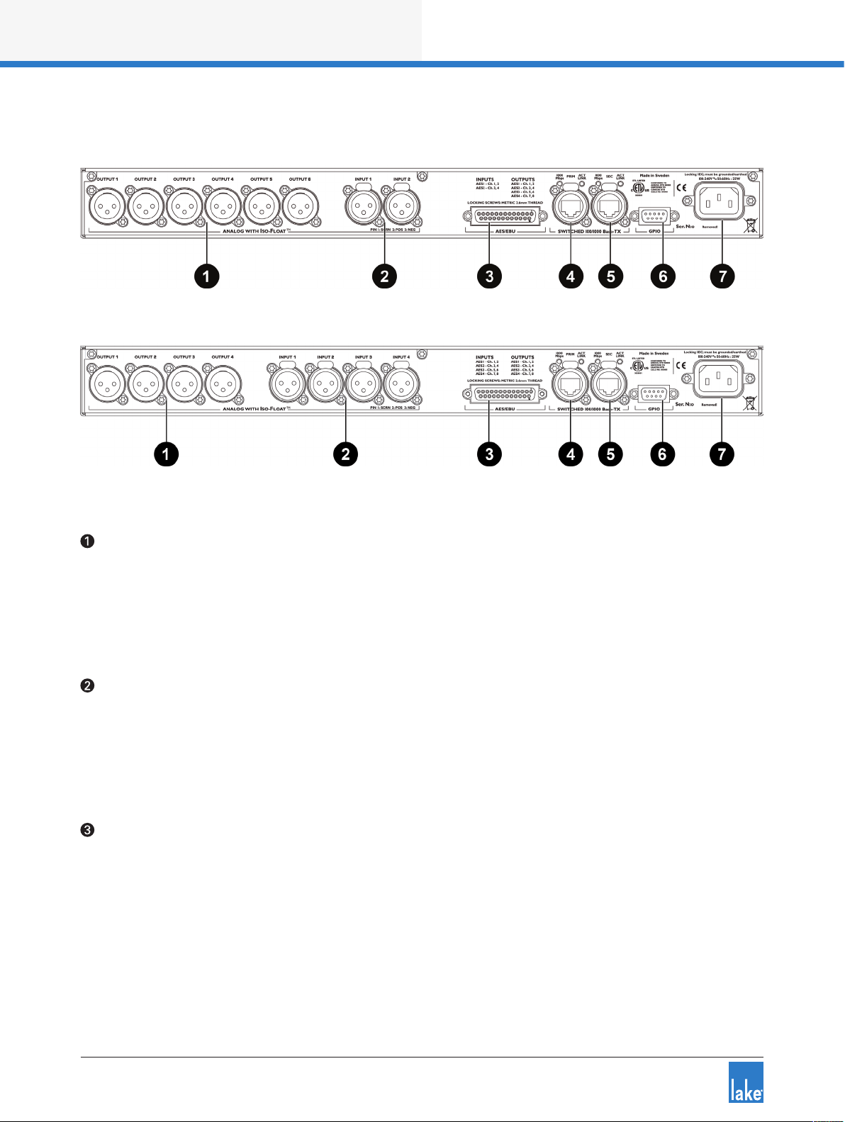
4.2 Back Panel Overview
Figure 4-2: LM 26 Back Panel Layout
Figure 4-3: LM 44 Back Panel Layout
Analog Outputs
Analog outputs are provided via standard XLR3M connections. The outputs are electronically balanced
and feature Lake Iso-Float circuitry; it is not recommended to use unbalanced connections. The output
impedance is 50 ohms, providing a maximum output level of +21 dBu. Please refer to section 7.1 for further
information.
Analog Inputs
Analog inputs are provided via standard XLR3F latching connectors. The inputs are electronically balanced
and feature Lake Iso-Float circuitry; it is not recommended to use unbalanced connections. The impedance
is 20 kohms (balanced), and the inputs can accept a maximum input level of +26 dBu. Please refer to section
7.1 for further information.
AES3 I/O
AES inputs and outputs are provided via a 25-pin DB25 connector. Inputs can be received on AES1 (Ch.1,2)
and AES2 (Ch.3,4) for all LM Series devices; the LM 44 also allows input from AES3 (Ch.5,6) and AES4
(Ch.7,8).
Outputs are via AES1 (Ch.1,2), AES2 (Ch.3,4), AES3 (Ch.5,6) and AES4 (Ch.7,8). Please refer to section 7.2
for further information.
8
Lake LM Series Operation Manual Rev 1.2.8

Product Overview
The sample rates available for AES3 inputs and outputs are 44.1, 48, 88.2, 96, 176.4, 192 kHz; input and
output sample rates can be congured to lock to different sample rates.
Primary Network Connector
The primary Neutrik RJ45 etherCON
®
connection provides integration into an Ethernet control network
which may include other Lake Processors and the Lake Controller software. Network connection permits full
control of all functions along with real-time metering from a remote position. This device supports the Dante
audio networking protocol, which allows transmission of multichannel, high-denition digital audio over the
same Ethernet connection.
Use the primary connector when using a star network topology, consisting of individual Cat-5e connections
between the devices and an Ethernet switch. Alternatively this connection can be used to daisy chain
directly to another Lake Processor. The daisy chain topology should not be used with Dante.
For a technical reference of the Ethernet Port, please refer to section 7.3. Additional information is available
in the Lake Network Conguration Guide.
The Ethernet ports automatically switch to operate at Ethernet data
rates of 100 Mbps or 1000 Mbps, and allow straight or crossed
network cables. Two LEDs above each port indicate valid network
connection (LINK) and network activity (ACT).
Secondary Connector
The secondary network connector can be used to daisy-chain multiple LM & PLM Series and legacy Dolby
and Lake devices. Alternatively, a Dante dual-network topology can be created by connecting all secondary
network connectors to a separate Ethernet switch, ensuring full redundancy in the event of a network
component failure.
Additional processor conguration is required for a
dual redundant network setup. See the Lake
Controller Operation Manual for further details.
For a technical reference of the Ethernet Port, please refer to section 7.3. Additional information is available
in the Lake Network Conguration Guide.
When connecting multiple devices to an Ethernet
network, care must be taken NOT to create a
closed loop which causes network malfunction.
Lake LM Series Operation Manual Rev 1.2.8
9

Product Overview
GPIO Connector
A 9-pin GPIO (General Purpose Input Output) connection is provided to enable integration with external
systems such as alarm/re systems, providing basic control of power state, mute along with fault notication to an external monitoring system. Please refer to sections 6.10.4.4 and 7.4 for further details.
Mains Power Connector
A universal power supply capable of accepting 70-265 V ~ 50-60 Hz : 25 W is built into LM Series devices.
The IEC power cable provided includes a locking feature via a pin on the bottom of the connector; the
connector can accept standard or locking IEC power cables.
The power supply must be connected to AC mains using a power cable with a correctly wired plug for the
country of operation.
10
Lake LM Series Operation Manual Rev 1.2.8
Signal Flow and Lake Processing
5. Signal Flow and Lake Processing
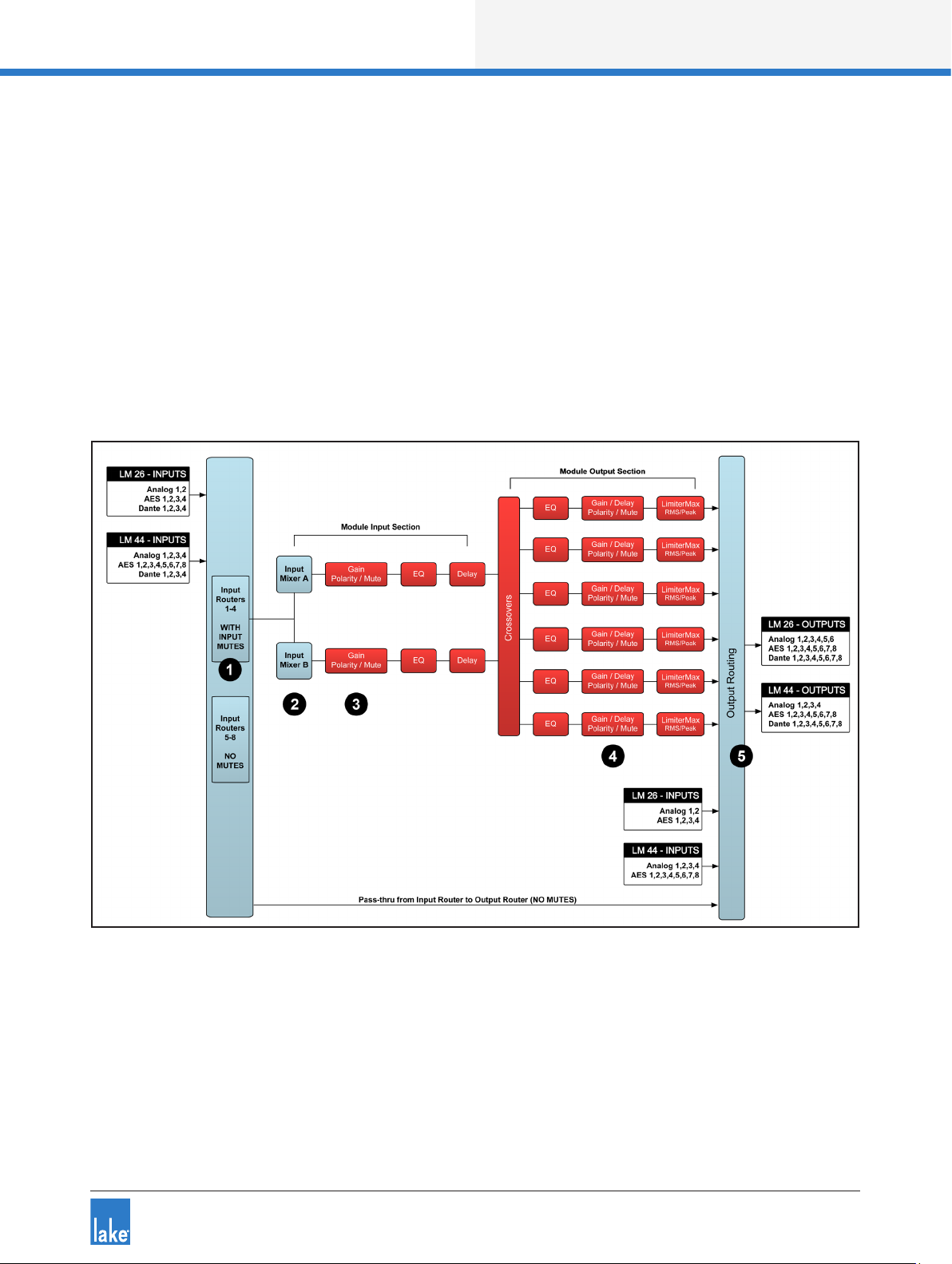
5.1 Signal Flow
The gures below depict the audio signal ow for LM Series devices congured in both Contour and Mesa
modes. It is worth noting that this sophisticated device provides up to ve points in the signal chain where
the signal level can be adjusted, muted or disconnected (depending on whether congured in Contour or
Mesa Mode as described below). The blue sections represent Frame data, and the red sections represent
Module data - please refer to the Lake Controller Operation Manual for further information.
Important information regarding correct setting of the gain structure can be found in section 9.1.
Figure 5-1: LM Series Signal Flow (Contour Mode)
Lake LM Series Operation Manual Rev 1.2.8
11
Signal Flow and Lake Processing
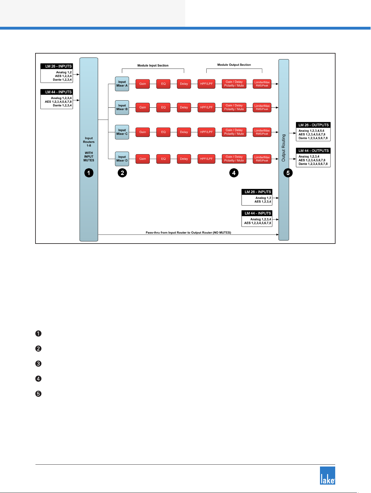
Figure 5-2: LM Series Signal Flow (Mesa Mode)
Please refer to section 6.10.4.2 for information on changing the Frame conguration between Contour and
Mesa Modes.
5.1.1 Level Adjustments & Mute Points
The numbers below correspond the points identied in Figure 5-1 and Figure 5-2.
Input Router Stage - Input selection and MUTE
Input Mixer Stage - Router ON/OFF connection to mixer and gain settings
Module Input Stage - Mute (N/A for LM Series Mesa Mode) and gain settings
Module Output Stage - Mute and gain settings
Output Router Stage - Output ON/OFF routing connections
In Contour Mode, a Module can be connected to Input Routers 1-4 providing all ve stages of mute/connectivity functionality via the front panel interface or the Lake Controller; Input Routers 5-8 allow stage 1 input
selection only (MUTE unavailable), along with stage 5 output ON/OFF routing connections (i.e. pass-thru).
12
Lake LM Series Operation Manual Rev 1.2.8

Signal Flow and Lake Processing
In Mesa Mode, a Module can be connected to any of the eight input routers, providing four stages of mute/
connectivity (stage 1,2,4 & 5).
If the required audio signal is not passing correctly,
verify the connection, mute and gain settings at all
ve stages.
5.2 Lake Processing and Control
As outlined in section 2.2.1, this device integrates seamlessly into the Lake Processing environment,
providing all features, functionality and connectivity associated with all Lake Processors. The internal Lake
Processing includes programmable crossovers, EQ, dynamics and other functions, and can be fully controlled via the supplied Lake Controller software. Additionally, many functions can be controlled or accessed
directly via the front panel.
The Lake Controller Operation Manual and Lake Network Conguration Guide are supplied on the accompanying CD-ROM and additional documentation is available from the Start Menu after software installation.
Visit http://lakeprocessing.com to download the latest software, rmware and documentation for your
devices.
5.3 Modules and Frames
5.3.1 Overview
A Frame represents one physical Lake Processor (e.g. LM 26 or LM 44). In Contour Mode, a maximum
of two Modules are contained within each Frame; these are referred to as Module A and Module B. The
number of Modules shown in a given Frame is also dependent upon the signal processing conguration of
that Frame. In Mesa Mode each Frame contains four Modules labelled A, B, C & D.
In Contour Mode, each Module can be congured as a Classic Crossover (Bessel, Butterworth, LinkwitzRiley), as a Linear Phase Crossover, or as multiple full bandwidth Auxiliary Outputs. The default conguration
for the LM 26 is 2 x Classic 3-Way Modules, providing a total of six Module outputs. The default conguration for an LM 44 is four Mesa EQ Modules, providing a total of four Module outputs.
Please refer to the Lake Controller Operation Manual for further information.
5.3.2 Super Modules
Super Modules allow control of multiple Modules of the same type, distributed across multiple Frames, as
a single entity within the Lake Controller software. A change made in the Super Module is replicated across
all assigned Modules, resulting in improved efciency in system conguration and a reduction of on-screen
icons within the Lake Controller software.
Lake LM Series Operation Manual Rev 1.2.8
13

Signal Flow and Lake Processing
The key benet of this feature is the ability to connect and control crossovers, levels and EQ across multiple
hardware devices simultaneously from the Lake Controller. For example, one device may be driving sub and
low-frequency speakers, while another device controls mid-range and hi-frequency drivers. Using a single
adjustment the crossover points between the two devices can be changed simultaneously.
Please refer to the Lake Controller Operation Manual for further information regarding Super Modules.
5.4 Loudspeaker Processor (Contour Mode) Overview
In Contour Mode, LM Series devices may be congured with up to two processing Modules containing
a total of up to six processing Module outputs as shown in Figure 5-1 on page 11. Each set of processing
elements is referred to as a Module and can be congured as crossovers, full-bandwidth auxiliary outputs,
or a combination of the two. The relationship between inputs and outputs is dened via the Lake Controller
or via the front panel I/O CONFIG Menu.
The Lake Processing system provides two distinct categories of crossovers:
▸ Innite Impulse Response lters (IIR) such as the classic Bessel, Butterworth or Linkwitz-Riley types;
these are available with slopes ranging from 6 dB/octave to 48 dB/octave.
▸ Finite Impulse Response lters (FIR) providing zero phase shift with steep transition slopes at the
crossover frequencies. These are also referred to as Linear Phase Crossovers.
Further details on these types of crossovers and information on conguring various module types can be
found in the Lake Controller Operation Manual.
5.5 System Equalizer (Mesa Mode) Overview
In Mesa Mode, an LM Series device provides four processing Modules with independant EQ, HPF/LPF,
Gain, Polarity, Delay and Limiters as shown in Figure 5-2 on page 12. The relationship between inputs and
outputs is dened via the Lake Controller or via the front panel I/O Input Cong Menu.
Please refer to the Lake Controller Operation Manual for addiitonal information on Mesa Mode and associated I/O routing.
5.6 Switching between Contour and Mesa Mode
When switching between Contour and Mesa Modes, all current Frame conguration data is lost (Presets
are retained) and the device is completely recongured into the selected Mode. Ensure you have stored any
existing frame conguration data before conguring into a different mode.
The device conguration may be changed either via the Front Panel MENU > FRAME > FRAME RST (refer
to section 6.10.4.2) or via the Lake Controller MODULES > I/O CONFIG > FRAME CONFIG menu (refer to
the Lake Controller Operation Manual).
14
Lake LM Series Operation Manual Rev 1.2.8

Signal Flow and Lake Processing
5.7 Files and Presets
The Lake system provides various methods for storing and recalling Module, Frame, or system-wide data.
An overview is provided below; for further information please refer to the Lake Controller Operation Manual.
5.7.1 Module, System and Sub-System Conguration Files
Module, System and Sub-System Conguration les are stored on the Lake Controller PC, and data is
passed across the network when recalling or storing these type of les.
▸ A Module le is the smallest set of data that can be stored and recalled; it contains crossover, gain,
delay, and limiter information for an individual loudspeaker (i.e. the data shown in red in the signal ow
diagrams in section 5.1). A Module le may be recalled into other Lake devices. It is not possible to
store a Module File directly on the hardware device.
▸ A System or Sub-System Conguration File contains a set of Module le information in addition to
Frame related information such Group data and I/O conguration (i.e. the data shown in blue in the
signal ow diagrams in section 5.1).
5.7.2 Frame and System Presets
This device allows the complete processor conguration to be stored as a Frame Preset on the
hardware unit itself. Presets can be recalled via the front panel (please refer to section 6.10.6) or via the
Lake Controller software (please refer to the Lake Controller Operation Manual). Presets can be stored into
the device using the Lake Controller or the LM Series Preset Manager utility.
A maximum of 100 Frame Presets can be stored on this device. The data within a Frame Preset includes the
congurations of both Modules in the Frame, including all levels, crossover, EQ, input mixer, output routing,
and all other Module, Frame and Group parameters. As Frame Presets are stored in the device, complete
processor congurations may be recalled without the need to connect the device to a PC.
Using the System Presets function in the Lake Controller, entire system congurations can be stored and
recalled across a network of LM & PLM Series devices, Dolby Lake Processors, Mesa Quad EQ and the
Contour Pro 26. This enables fast retrieval and switching of entire system congurations as minimal data is
being sent between the Controller and Processors.
Lake LM Series Operation Manual Rev 1.2.8
15

Front Panel Interface
6. Front Panel Interface
An overview of the front panel interface is provided in section 4.1. This chapter describes each cluster of
controls as shown in Figure 6-1.
Figure 6-1: Front Panel Interface
6.1 Overview
The front panel interface is framed by two sturdy cast aluminium handles . The majority of functions
on LM Series devices can be operated and monitored via the following controls and display features: On/
standby button , front-panel LCD display screen , function buttons , rotary encoder , a
dynamic illuminated I/O divider and the dedicated Module input output mute buttons and LED meters .
The front panel has two basic modes: Meter Mode and Menu Mode.
▸ Meter Mode provides the following views: Home View (default), Input Meters View (Mesa Mode only)
and I/O Status View. To navigate through these views, press the METER button. Please refer to section
6.9 for further information on Meter Mode.
▸ Menu Mode provides various menus for viewing and editing parameters and is selected by pressing the
MENU button. Select the required submenu by pressing the associated button. Please refer to section
6.10 for further information on Menu Mode.
6.1.1 Warning, Fault and Mute Indications
Fault or warning conditions are indicated via the LEDs embedded in the dynamic function buttons; a simultaneous description is shown adjacent to the button, on the LCD.
Further information on faults and warnings is provided in section 6.7.2 and section 8.1.
16
Lake LM Series Operation Manual Rev 1.2.8
Loading...