


USER MANUAL HEADLINES
|
|
LAB 4000 |
|
|
USER MANUAL |
Unpacking |
2 |
Rev. 3 |
|
||
Warnings |
2 |
|
|
User responsibility 2
1.Speaker damage
2.Speaker output hazard.
3.Radio interference.
Introduction 3
1.Front panel
2.Rear panel
Installation 4
1.Mounting
2.Cooling
3.Operating voltage
4.Grounding
5.Power consumption
6.Denmark: National deviation
7.Switzerland: National deviation
8.Input connections
9.Connecting speakers
10.Impedance matching (MLS-switches)
Design features |
10 |
•Cooling
•Light weight
•Regulated power supply
•Safety approvals
•EMC approvals
Specifications
11
•EMC-declaration
Appendix A |
12 |
•Mains voltage selection
Operation modes |
8 |
Maintenance |
12 |
||
|
|
|
|||
1. |
Stereo |
|
Troubleshooting |
12 |
|
2. |
Tandem mono |
|
|||
3. |
Bridged mono |
|
|
|
|
4. |
Stereo reverse |
|
Warranty and disclaimers |
13 |
|
|
|
|
|||
Operation |
8 |
• |
General |
|
|
• |
International |
|
|||
1. |
Operation precautions |
|
|
|
|
2. |
Powering up -Soft start |
Technical assistance and services |
13 |
||
3. |
Input attenuators |
|
|||
4. |
Gain switch |
|
• |
International |
|
5. |
Indicators |
|
• |
Factory services |
|
|
|
|
|
||
Protections 9
1.Clip-limiter
2.Thermal protection
3.VHF protection
4.Short circuit protection
5.Adaptive Fuse Saver (AFS)
6.AC mains voltage protection
7.D.C. protection
1

Unpacking
Carefully open the shipping carton and check for any noticeable damage. Every LAB.GRUPPEN amplifier is tested and inspected before leaving the factory and should arrive in perfect condition. If found to be damaged, notify the shipping company immediately. Only the consignee may institute a claim with the carrier, for damage incurred during shipping. Be sure to save the carton and packing materials for the carrier's inspection.
It is also advisable, to save the carton and packing material, even if the amplifier is undamaged. Should you ever need to ship the amplifier, use the original packing.
Warnings
Read this before you are operating your amplifier:
•Do not use this amplifier if the power cord is broken or frayed.
•Always operate the unit with the chassis ground wire connected to the electrical safety earth.
•Do not parallel or series connect an amplifier output, with any other amplifier output. Do not connect the amplifier output to any other voltage source, such as battery, mains source, or power supply, regardless of whether the amplifier is turned on or off.
•Do not run the output of any amplifier back into another channel's input.
•Do not block the air intake or exhaust ports. Do not operate the amplifier near heat producing devices such as radiators, stoves etc.
•Do not spill water or other liquids into or on the unit. Do not operate the amplifier if suspected or standing in liquid.
•Do not remove top or bottom covers. Removal of the cover will expose hazardous voltages. There is no serviceable parts inside and removal may void warranty.
•Keep this manual for future reference.
User responsibility
1.Speaker damage
Your amplifier is very powerful and can be potentially dangerous to both loudspeakers and humans alike. Many loudspeakers can be easily damaged or destroyed by overpowering, especially with the high power available from a bridged amplifier. Always check the speakers continuous and peak power capabilities.
Even if the gain is reduced by using the amplifier's front panel attenuator, it is still possible to reach full output power, if the input signal level is high enough.
2.Speaker output hazard
Power amplifiers are capable of producing hazardous output voltages. To avoid electrical shock, do not touch any exposed speaker wiring, while the amplifier is operating. See page 6 about outputs for proper connection of speakers.
3.Radio interference
This product has been tested, and complies with the limits for the European Electro Magnetic Compatibility (EMC) directive. These limits are designed to provide reasonable protection against harmful interference between electrical equipment. This product uses radio frequency energy, and if not used or installed in accordance with the operating instructions, it may cause interference to other equipment, such as radio receivers. However, there is no guarantee for no interference even if the amplifier is EMC approved.
If the amplifier cause interference, which can be easily determined by turning the amplifier on and off, the user can correct the interference by one or more of the following steps:
1.Increase the proximity between the equipment.
2.Connect the AC cord to an outlet on a different circuit from that to which the affected unit is connected.
3.If a radio receiver is interfered (normally amplitude modulation); reorient the antenna.
4.Check if the affected unit complies with the EMC limits for immunity, (CE-labelled).
If not, address the problem with the manufacturer or supplier. All electrical products sold in the EC must be approved for immunity against electromagnetic fields, high voltage flashes, and radio interference.
2
Introduction
Thank you for purchasing a LAB.GRUPPEN power amplifier. The amplifier you have chosen is the culmination of many years of Research and Development. This amplifier makes amplification more controllable instead of the traditional "Boring black box" you have become accustomed to.
Please take some time and read this manual to familiarize yourself with the advanced features of this amplifier.
The front panel |
|
|
|
|
|
|
|
|
|
|
6 |
|
|
3 |
4 |
|
5 |
|
6 |
8 |
9 |
|
|
|
|
|
VHF |
|
|
|
|
|
|
|
|
|
|
TEMP |
|
|
|
|
AFS |
|
|
|
|
|
|
|
|
|
|
|
|
|
|
|
|
CLIP |
|
|
|
|
AC |
|
|
|
|
|
-5 |
|
|
|
|
|
|
|
|
|
|
-10 |
|
|
|
|
|
|
|
|
|
|
-15 |
|
|
|
|
|
|
|
CH. A |
|
|
-20 |
|
CH. B |
|
|
|
|
|
|
|
|
-25 |
|
|
|
|
|
|
-12 |
-10 |
-7 |
|
ON |
-12 |
-10 |
-7 |
|
|
|
|
|
|
|
|
|||||
|
-16 |
|
|
-5 |
|
-16 |
|
-5 |
|
|
|
-20 |
|
|
-3 |
|
-20 |
|
-3 |
|
|
|
-40 |
|
|
-1 |
|
-40 |
|
-1 |
|
|
|
-80 |
dB |
0 |
|
|
-80 |
dB |
0 |
|
|
|
|
|
|
4000 |
|
CONVERTIBLE POWER AMPLIFIER |
|
|
||
|
|
|
|
|
|
|
|
|
||
1 |
|
2 |
|
|
|
|
2 |
|
|
7 |
|
|
|
|
|
|
|
|
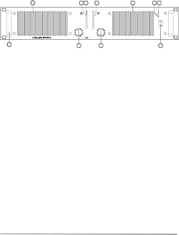
Figure 1. Front panel
1.Carry/protection handle
Both handles can be used to carry the amplifier, they also act as protection for the front panel. If so desired they can be removed (by removing the screws behind the front panel) for fixed installations, or racks where the front covers are to shallow.
2.Input level attenuators
These controls are used to alter the signal level entering the amplifier. They are calibrated in dB to help set up active loudspeaker systems or cut down unwanted noise from the input signal.
(See page 9).
3.Over temperature protect indicator
This indicator is lit if the amplifier tries to operate above its maximum operating temperature(90oC). The indicator first comes on as a warning to either turn down the input level or check the cooling arrangements after which point the amplifier will mute the input signal. When the cooling fans have returned the output heat sinks to the normal operating temperature the input signal is unmuted.
4.VHF protect indicator
This indicator lights when constant signals, above 12 kHz at full power, are present at the output terminals. When this happens the input signal is muted and the process cycles until the VHF signal is no longer present. (See page 9).
5.Clip/limit indicator
This indicator tells when the amplifier output is clipping or limiting. The two different states can be told apart:
•When the clip limiter is engaged it flickers briefly. (See page 10).
•When the clip limiter is not engaged it lights for a longer period.
6.Fan grill filter.
A foam filter is located behind the front panel to prevent dust entering the amplifier.
7.Power actuator
This is used to start the amplifier. (See page 5 and 8)
8.AC indicator
Indicate if AC voltage is present .
9.AFS indicator
Indicate if the adaptive fuse saver is activated.
3

The rear panel
1 |
|
|
|
|
4 |
5 |
|
6 |
|
7 |
|
8 |
5 |
4 |
|
|
|
|
|
1 |
|
|
|
|
|
|
|
|
|
INPUT |
|
|
CH. A |
|
|
|
|
|
|
|
|
OUTPUT |
.B |
|
|
|
|
|
CH. B |
B |
.l B |
|
|
|
|
|
|
|
|
OUTPUT CH.A |
||
|
|
|
|
|
|
|
|
|
|
|
|
|
|
|||||||
|
M LS |
S w itc h |
|
|
|
|
|
N o rm al P o .l |
R ev er se P o |
S t e re o L ni k A + B |
Ga ni 4 1 dB |
Ga ni 2 9 dB |
|
|
|
|
|
M LS |
S w itc h |
|
|
|
|
d B |
|
|
|
|
|
|
|
|
|
|
|
|
|
|
d B |
|
|
|
|
0 |
|
|
|
|
|
Mono Bridge |
|
|
|
|
|
|
|
0 |
|
|
||
|
|
-2 |
|
|
|
|
|
|
|
|
|
|
|
|
|
|
|
- 2 |
|
|
1+ CH.B+ |
-4 |
|
|
XLR |
|
1 / 4 “ |
|
|
|
|
|
|
|
|
|
|
- 4 |
1+ CH.A+ |
||
-5 |
On |
Off |
|
|
|
|
|
|
|
|
On |
Off |
|
- 5 |
||||||
1- CH.B- |
Pin 1 |
Gnd |
Sleeve |
|
|
|
|
|
|
|
|
1- |
CH.A- |
|||||||
|
|
|
Clip Limiter |
|
|
|
|
|
|
|
Clip Limiter |
|
|
|
|
|||||
|
|
|
|
|
2 |
Pos |
Tip |
|
|
|
|
|
|
|
|
|
|
|
|
|
|
|
|
|
Made in Sweden |
3 |
Neg |
Ring |
230V AC |
40-440Hz |
|
|
4000 |
Patent pend |
|
Ser. N:o |
Removed! |
|
|
||
|
|
|
|
|
Must be grounded |
|
Power consumption: 2300 watts |
|
|
|
|
|
|
|
|
|||||
|
2 |
|
|
3 |
|
|
|
|
|
|
|
|
9 |
|
|
3 |
|
|
2 |
|
Figure 2. Rear panel
1.Speaker connector
This type of speaker connector may be unfamiliar to some users. A full description is found in the operation section. (See page 7).
2.MLS™ switches
These switches are used to select the maximum output power . (See page 7).
3.Clip limiter switch.
Turns the clip limiter on and off. (See page 9).
4.Input jack
Alternative to using input XLR or for linking inputs with other amplifiers. (See page 6).
5.Input signal XLR (See page 6).
6.Phase reverse switch for channel B
For reversing the input signal phase of channel B to allow bridged operation. (See page 8).
7.Link switch
Allows a single input to drive both channels simultaneously. (See page 8).
8.Gain select switch
Allows amplifier gain to be switched between 29dB and its normal gain at 0.775mV input sensitivity. (See page 9).
9. AC line cord (See page 5)
Installation |
|
|
|
|
|
|
|
|
|
|
|
Should a heat sink get too hot, its |
sensing |
circuit |
|||||||||
1. |
Mounting |
|
|
|
|
|
|
|
|
|
|
|
will |
mute |
the hot channel. If the power |
supply |
|||||||
|
|
|
|
|
|
|
|
|
|
|
overheats, another sensing circuit will mute all |
||||||||||||
The amplifier is two rack units high (2U) and will |
|||||||||||||||||||||||
output channels, until it cools down to a safe |
|||||||||||||||||||||||
mount in a standard EIA 19 inch rack. Amplifiers |
|||||||||||||||||||||||
operating temperature. |
|
|
|
|
|
|
|||||||||||||||||
may be stacked directly on top of each other. There |
|
|
|
|
|
|
|||||||||||||||||
Make sure that there is an adequate air supply |
in |
||||||||||||||||||||||
is no need for spacing between units. If it |
is |
the |
|||||||||||||||||||||
front of the amplifier and that the rear of the |
|||||||||||||||||||||||
intention |
to |
fill |
a |
rack |
with |
amplifiers, |
we |
||||||||||||||||
amplifier has sufficient space to allows the exhaust |
|||||||||||||||||||||||
recommend racking is |
started from the bottom of |
||||||||||||||||||||||
to escape. If the amplifier is rack mounted, do not |
|||||||||||||||||||||||
the rack. It is also recommended that rear supports |
|||||||||||||||||||||||
use covers or doors on the front or rear of the rack. |
|||||||||||||||||||||||
are used for amplifiers mounted in |
the middle of |
||||||||||||||||||||||
For |
fixed |
installations |
with |
a |
central |
cooling |
|||||||||||||||||
the |
rack, especially |
if |
used |
as |
part of |
a portable |
|||||||||||||||||
system, usually found in fixed installations with a |
|||||||||||||||||||||||
system. |
|
|
|
|
|
|
|
|
|
|
|
|
|||||||||||
|
|
|
|
|
|
|
|
|
|
|
|
dedicated rack room, it may be necessary |
to |
||||||||||
|
|
|
|
|
|
|
|
|
|
|
|
|
|
||||||||||
2. |
Cooling |
|
|
|
|
|
|
|
|
|
|
|
calculate the maximum |
heat |
emission. |
Refer |
to |
||||||
|
|
|
|
|
|
|
|
|
|
|
Power consumption on page 5. |
|
|
|
|
|
|||||||
Your amplifier uses forced air cooling |
system |
to |
|
|
|
|
|
||||||||||||||||
|
|
|
|
|
|
|
|
|
|||||||||||||||
maintain a low and even operating temperature. All |
|
|
|
|
|
|
|
|
|
||||||||||||||
LAB.GRUPPEN amplifier, which are fan |
|
|
|
|
|
|
|
|
|
||||||||||||||
ventilated, |
have front |
to |
rear |
cooling. |
There |
|
are |
3. |
Operating voltage |
|
|
|
|
|
|
||||||||
several reasons for this, one is |
that |
there's |
usually |
|
|
|
|
|
|
||||||||||||||
A label just below the mains cable on the rear of |
|||||||||||||||||||||||
cooler air outside the rack than inside and therefore |
|||||||||||||||||||||||
the amplifier indicates the AC mains voltage, for |
|||||||||||||||||||||||
the |
amplifiers can run at |
higher continuos |
power |
||||||||||||||||||||
which the amplifier is wired. Connect the power |
|||||||||||||||||||||||
levels without |
thermal |
problems. |
Never |
try |
|
to |
|||||||||||||||||
|
cable only to the AC source referred to on the label. |
||||||||||||||||||||||
reverse the air flow, as the Intercooler® need a |
The warranty will not cover damage caused by |
|
|
||
|
connecting to the wrong type of AC mains. |
|
pressure chamber between the fans and heat sink, |
For converting a 230 volt amplifier to 115 volt or |
|
vice-versa, see Appendix A. |
||
and this only works in one direction of the air flow |
||
|
||
(see Design features on page 8). |
|
4
 Loading...