

Page 1
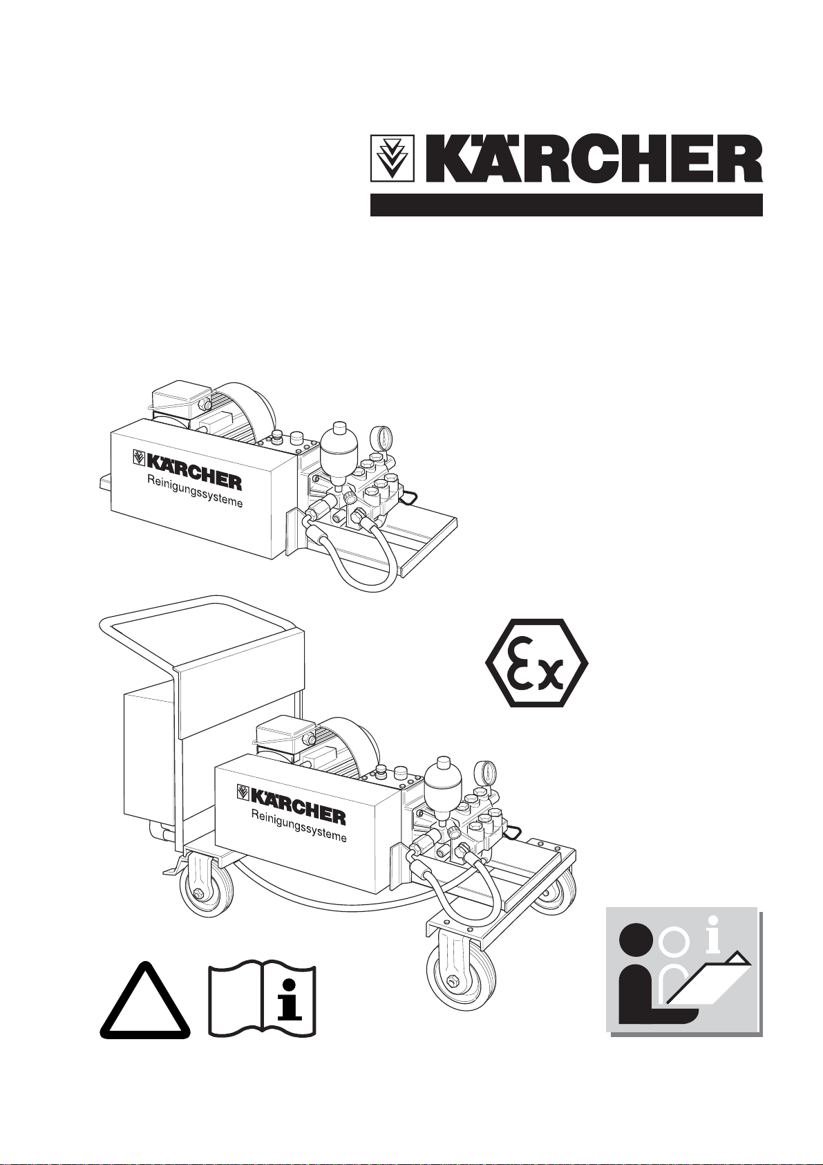
SHD-R 3000
!
Betriebsanleitung
www.karcher.com
5.956-486 A2005937 (06/03)
Page 2

Operating Instructions
i
i
To be handed to the operator
Read these instructions carefully before starting up the unit
Retain for future reference
Notes about these operating
instructions
Before starting up the interior cleaner for the
first time, please carefully read through
these instructions. In particular, you should
note all the safety information. Store these
instructions in a safe place for future use.
For whom are these instructions
intended
All users
Users are persons who have received
instruction on how the system functions,
operators and trained specialists.
Trained specialists
Trained specialists are persons who are
professionally qualified to install and
commission this type of system.
Cleaning liquids
Please do not allow them to get into the
environment. Please protect the soil and
dispose of waste oil in an environmentally
friendly way.
Waste water containing mineral oil (i.e.
petrol, etc.)
Please do not allow this waste water to get
into the ground, bodies of water or the
sewers.
Mineral oil in the high-pressure pump
Mineral oil is used to lubricate the highpressure pump. The waste oil resulting from
an oil change, any oil and water mixture that
may occur, and rags that have been soaked
in oil should be delivered to a proper
collection point for disposal.
Important!
Envir onmental protection
Please dispose of the packaging in an
environmentally friendly way.
The packaging materials are recyclable.
Please do not throw the packaging into the
domestic waste but in the appropriate
recyclable waste collection containers
instead.
Please dispose of old units in an
environmentally friendly way
Old units contain valuable recyclable
materials, which should be reused. You
should never allow oil and similar materials
to get into the environment. Therefore,
please dispose of old units via suitable
collection systems.
Waste oil may only be disposed of by the
operators of special collection points.
Please deposit your waste oil at one of
these locations. Polluting the environment
with waste oil is a criminal offence.
Detergents
KÄRCHER detergents possess demulsifying
properties (ASF). This means that they do
not interfere with the function of an oil separator.
Important
These instructions contain descriptions of
different types of system, accessory kits
and other supplementary components.
There are significant differences between
the various parts so that you should not
encounter any problems with identifying all
the parts in your particular type of system.
Page 3

SHD-R 3000
Table of contents
English
A. For your safety
1. Safety information and instructions
2. Noise protection
3. Authorized operators
4. Personal protective equipment
5. Emergency drill
6. Safety devices
7. Applicable regulations
8. Using the system for its intended
purpose
9. Special conditions in hazardous area
10. Schematic diagram of area
classification
11. Area classification
B. Types of system, and operating
information
1. Types of system
2. System start-up
3. System shut-down
E. Care and maintenance
1. General information
2. Maintenance schedule
3. Maintenance tasks
F. Troubleshooting
1. Fault-finding
G. Mounting kits and accessories
1. Mounting kits (non-hazardous area)
2. Mounting kits (hazardous area)
3. Accessories
H. Warranty
I. System installation
J. Declaration of Conformity
K. Test record
C. System functions
D. Technical specifications
5.956-486 A2005937 (06/03)
1
Page 4
English
!
i
!
A. For your safety
SHD-R 3000
1. Safety information
and instructions
The following symbols are used throughout
these Operating Instructions:
Danger!
Denotes an immediate and present danger.
Failure to observe this notice could lead to
severe injury or death.
Caution!
Denotes a potentially hazardous situation.
Failure to observe this notice could lead to
minor injuries or damage to property.
Important!
Denotes operating hints and important
information.
Errors in operation or misuse can result in
danger to the operator or other persons
due to:
All persons charged with the installation,
commissioning, operation, maintenance or
service of the machine are required:
to be appropriately qualified,
to read and observe these operating
instructions,
to be aware of and observe associated
regulations.
2. Noise protection
The sound level generated by the system is
80 dB(A).
A noise hazard can occur if the water jet is
directed at resonating components (e.g.
large metal panels). In this case a hearing
protection device must be worn.
3. Authorized operators
The operation of the system is restricted to
persons over the age of 18 who have
received proper instruction as to how this
system is to be used (For exceptions for
trainees see BGV D15 Art. 6).
high water pressure,
hot liquids,
high voltages,
detergents and solvents,
Explosion hazard.
In order to avoid errors in operation or
potentially dangerous situations, read the
following before starting the system up for
the first time:
all safety information in the enclosed
brochure "Safety information for highpressure cleaning units" No. 5.951-949,
these operating instructions,
the legal requirements that are currently
applicable in your country.
4. Per sonal protective equipment
Danger!
Health hazard due to cleaning fluids.
Wear the prescribed protective equipment
for the cleaning liquid to be used, e.g.
protective clothing/overalls,
protective goggles or face mask,
watertight gloves,
watertight shoes.
A1
5.956-486 A2005937 (06/03)
Page 5
SHD-R 3000
!
i
A. For your safety
English
5. Emergency drill
Turn mains supply voltage off at system
master switch.
Turn off supply of cleaning liquid.
If a handgun is being used, release any
remaining pressure in the system by
pressing the lever on the handgun.
6. Safety devices
Safety valve
Danger!
Injury hazard due to excessive pressure
within system. Do not adjust safety valve.
The safety valve has been preset and
sealed in the factory. Adjustments should
only be made by a Kärcher Customer
Service engineer.
If acids, alkaline solutions or solvents are to
be used:
Observe the legal requirements that are
currently applicable in your country. In
Germany the regulations of the industrial
employer's liability insurance
associations apply (BGI 504).
Observe instruction leaflets provided by
manufacturers of the detergent
concentrates that are to be used with this
system.
Important!
According to the UVV (accident prevention)
Guidelines (BGV D15, Art. 23), highpressure sprayers must be checked by an
expert with the initial startup and at least
every 12 months thereafter. Kärcher
Customer Service engineers are qualified to
carry out the prescribed tests on your
system.
7. Applicable regulations
Accident prevent regulations
Working with liquid sprayers BGV D15.
If water is used as the cleaning liquid:
Observe local regulations for disposal of
waste water.
Waste water should be directed into the
main drainage system in accordance with
local regulations.
If the water to be used is drawn from the
main supply network:
Install a mains disconnector to EN 1717
(e.g. float tank with float valve),
BetrSichV (industrial safety regulations).
The results of the test procedures must be
recorded in writing. A form into which the
test results can be entered is shown in
Chapter K: Test Record.
5.956-486 A2005937 (06/03)
A2
Page 6
English
A. For your safety
SHD-R 3000
8. Using the system for its
intended purpose
This system is used for pumping a cleaning
liquid at high-pressure, for the purpose of:
with the handgun attached – cleaning
containers, boxes, cases and equipment
parts, etc.
with the interior cleaner attached –
cleaning enclosed containers, drums,
barrels, etc.
Cleaning the following is considered to be
contrary to the intended purpose, and is
strictly forbidden:
Persons and animals
The high-pressure jet represents a serious
injury hazard.
Loose objects
Such items could be catapulted away by
the high-pressure jet, causing damage to
property or injury to persons.
6. The pump's flow rate must not exceed
50 l/min when used with solvents.
7. The operating temperature of the cleaning
liquid, made up of water with cleaning agent,
must not exceed 60 °C.
8. The operating temperature of the cleaning
liquids must not exceed 20 °C where
solvents, lyes (alkali solutions) and acids
are used.
9. The pump must be inspected after a
reasonable operating time to ensure it has a
faultless condition and function (among
other things, bearings for wear, pump for
leaks, tension in the V-belt). Repair if
necessary.
10. The pump may only be operated with
cleaning liquids against which the materials
from which the pump is made have
adequate resistance.
11. Cleaning liquids, which contain
combustible solvent fractions, must
correspond to the temperature classes IIA
and IIB. Solvents in the temperature class
IIC must not be sprayed.
If water is used as the cleaning liquid, the
system must be protected against freezing
temperatures. Damage could be caused if
water freezes inside the system.
9. Special Conditions in a
hazardous area
1. The pump may only be used in zones
which correspond to the type of explosion
protection given on the rating plate.
2. The cleaning liquid must not contain more
than 1% by weight of undissolved solids.
3. The interior cleaner must be
electrostatically grounded.
4. The cleaning liquid pump may only be run
if it is filled with liquid.
5. The nominal pressure of the pump must
not exceed 50 bar when used with solvents.
12. The pump may only be operated in Zone
1 during cleaning. Ensure compliance with
the conditions applicable within the scope of
the BetrSichV (industrial safety regulations)
and other national conditions.
13. Hoses must be electrostatically
conductive (resistance R < 1 MΩ).
14. Only use cleaning liquids with a
conductivity G > 1000 pS/m.
15. All parts in contact with the media are to
be connected to the earth connection
system.
16. The electric motor used must have a
prescribed type testing certificate to
94/9/EC.
A3
5.956-486 A2005937 (06/03)
Page 7
SHD-R 3000
A. For your safety
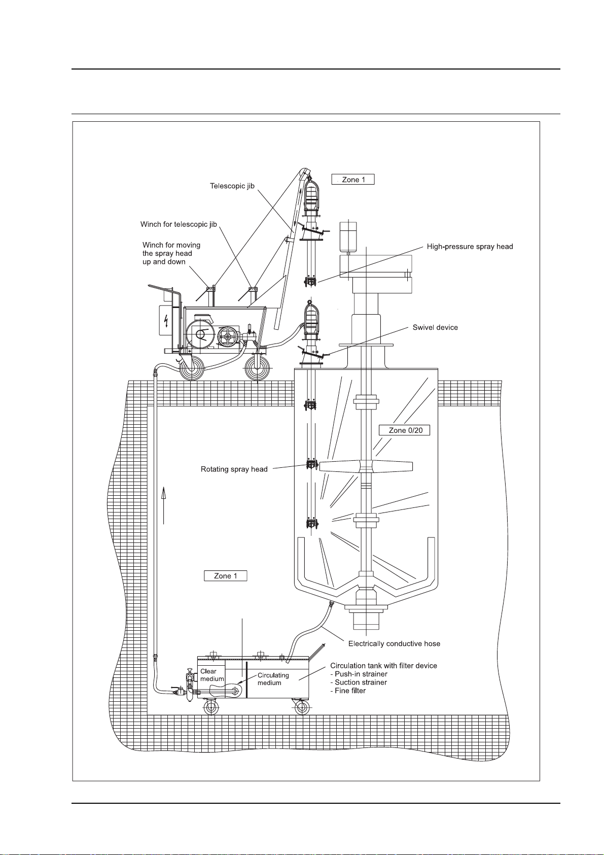
10 . Schematic diagram of area classification
English
5.956-486 A2005937 (06/03)
A4
Page 8

English
A. For your safety
11. Area Classification
In the BetrSichV and EN 1127-1, hazardous
(potentially explosive) areas are classified
into zones according to the frequency and
duration of the occurrence of hazardous,
potentially explosive atmospheres.
It is the responsibility of the owner/
operator to define these zones.
Notes on area classification are given in the
BetrSichV, EN 1127-1, BGR 104 - ExGuidelines of BG Chemie and in
DIN EN 60 079-10.
Zone 0
is an area in which hazardous, potentially
explosive atmospheres exists constantly,
for long periods of time or frequently as a
mixture of air and combustible gases,
vapours or mists.
SHD-R 3000
Zone 21
is an area in which hazardous, potentially
explosive atmospheres in the form of a
cloud of combustible dust contained in the
air can occasionally form during standard
operation.
Zone 22
is an area in which hazardous, potentially
explosive atmospheres in the form of a
cloud of combustible dust contained in the
air do not form during standard operation or
only for a short time.
Zone 1
is an area in which hazardous, potentially
explosive atmospheres consisting of a
mixture of air and combustible gases,
vapours or mists can occasionally form
during standard operation.
Zone 2
is an area in which hazardous, potentially
explosive atmospheres consisting of a
mixture of air and combustible gases,
vapours or mists do not normally occur
during standard operation or only for a short
time.
Zone 20
is an area in which hazardous, potentially
explosive atmospheres in the form of a
cloud of combustible dust contained in the
air exist constantly, frequently or for long
periods of time.
A5
5.956-486 A2005937 (06/03)
Page 9
SHD-R 3000
B. Types of system, and operating information
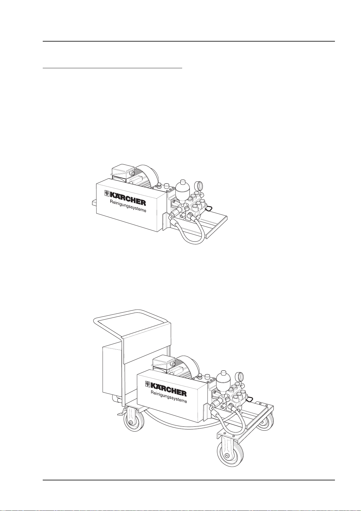
1. Types of system
Static or mobile systems
The static system
is intended to be installed on a base,
has been mounted onto a rigid steel
frame,
is most suitable for use in conjunction
with fixed-installation high-pressure lines.
English
The mobile system
has been mounted onto a trolley,
can be used in different locations.
5.956-486 A2005937 (06/03)
B1
Page 10
English
Cleaning liquids
B. Types of system, and operating information
SHD-R 3000
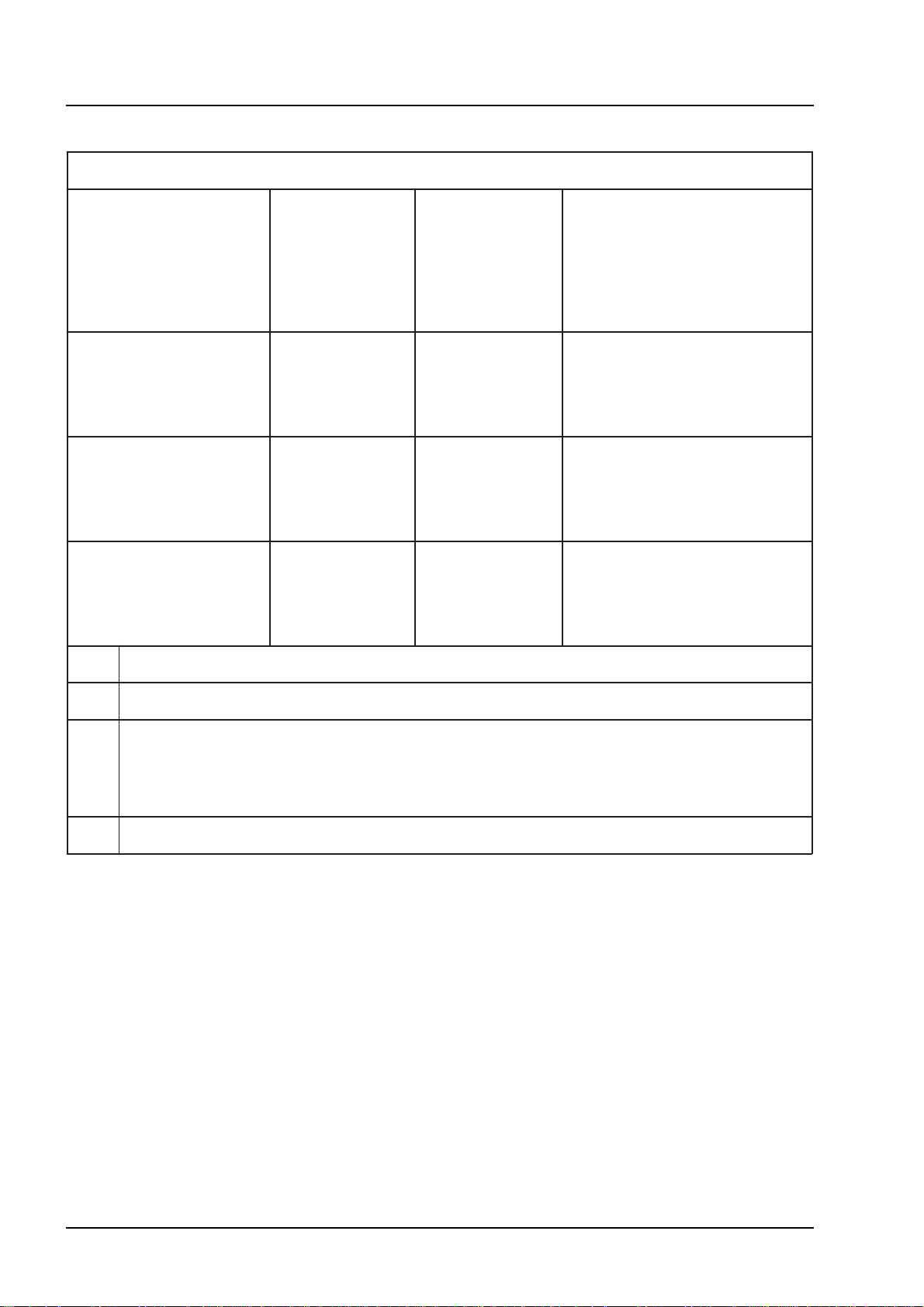
Type of system
(see rating plate)
SHD-R 3000 (F)
SHD-R 3000 (F) S
SHD-R 3000 (F) SVA
Cleaning liquid Working
pressure/
Pressure
setting for
safety valve
[bar]
-
Water
- VE
-water
-
Water with
*
50/65 Standard version
Kärcher-RM
-
Water
- VE
-water
-
Water with
*
85/100 Standard version with
Kärcher-RM
-
Water
- VE
-water
-
Water with
*
85/100 Pump parts that come into
Kärcher-RM
Comments
increased working pressure
contact with the cleaning liquid
are made from stainless steel.
VE Fully demineralised water
* Conditionally resistant, use possible, however Cu and Zn ions in the medium
RM
(F) Mobile system
Other cleaning liquids may only be used after being released by Kärcher!
RM Alkali cleaning agent: e.g. RM31 (max. 0 - 2%)
Acidic cleaning agent: e.g. RM25 (max. 0 - 1%)
Max. temperature + 60˚C
(Higher temperatures available on request - precompression pump required!)
B2
5.956-486 A2005937 (06/03)
Page 11
SHD-R 3000
)
Cleaning liquids
B. Types of system, and operating information
English
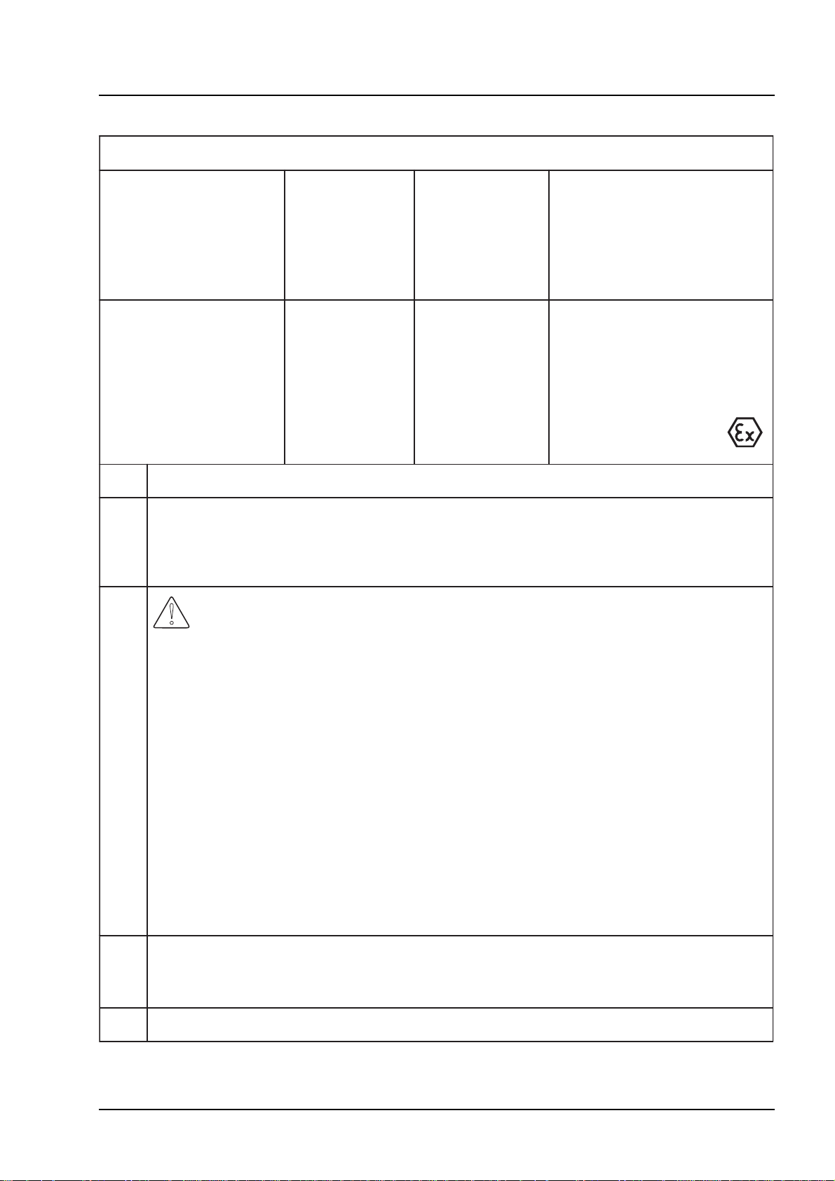
Type of system
(see rating plate)
SHD-R 3000 (F)
SSR
Cleaning liquid Working
-
Water
- VE
Water with
-
Kärcher-RM
- Acids
- Alkali
solutions
VE Fully demineralised water
RM
RM Alkali cleaning agent: e.g. RM31 (max. 0 - 2%)
Acidic cleaning agent: e.g. RM25 (max. 0 - 1%)
Max. temperature + 60 ˚C
(Higher temperatures available on request - precompression pump required!)
-water
1)
Comments
pressure/
Pressure
setting for
safety valve
[bar]
85/100 - The pistons are made
from ceramic materials,
other pump parts that
come into contact with
acids are made from
stainless steel.
2)
- Ex-versions possible.
1)
Caution!
Increased material removal in hydrochloric and sulphuric acid, therefore rinse/neutralise
immediately after use!
Reduced resistance against contaminated acids!
If necessary contact Kärcher!
Acids (max. temperature +
Nitric acid max. 10%
Acetic acid max. 10%
Formic acid max. 10%
Phosphoric acid max. 10%
Citric acid max. 10%
Sulphuric acid max. 0.5%
Hydrochloric acid max. 0.5%
2)
Sodium hydroxide solutions max. 10%, without hypochlorite fractions (max. temperature
+ 20 ˚C)
Potassium hydroxide max. 10%, without hypochlorite fractions (max. temperature + 20 ˚C
20 ˚C)
(F) Mobile system
Other cleaning liquids may only be used after being released by Kärcher!
5.956-486 A2005937 (06/03)
B3
Page 12
English
Cleaning liquids
B. Types of system, and operating information
SHD-R 3000
Type of system
(see rating plate)
SHD-R 3000 (F) SLA
SHD-R 3000 (F) LM
Cleaning liquid Working
pressure/
Pressure
setting for
safety valve
[bar]
–
Water
–
VE water*
85/100 –
– Water with
Kärcher-RM
– Alkali
solutions
–
Water
–
VE water*
2)
50/65 –
– Water with
Kärcher-RM
– Alkali
solutions
– Solvents
2)
3)
Comments
Version with increased
working pressure.
–
Leaked liquid is collected in
a pipe (leakage recycling).
–
Ex-versions possible.
Explosion-proof version.
–
Leaked liquid is collected in
a pipe (leakage recycling).
–
Additional pressure switch as
safety device (optional).
VE
*
RM
2)
3)
Fully demineralised water
Conditionally resistant, use possible, however Cu and Zn ions in the medium
Acidic cleaning agent: e.g. RM25 (max. 0 - 1%)
Max. temperature + 60
(Higher temperatures available on request - precompression pump required!)
Sodium hydroxide solutions max. 10%, without hypochlorite fractions
(max. temperature + 20 ˚C)
Potassium hydroxide max. 10%, without hypochlorite fractions (max. temperature + 20 ˚C)
Solvents (max. temperature + 20 ˚C)
1. Hydrocarbons, e.g.: petroleum
2. Aromatic compounds, e.g.: benzene, toluol
3. Ketones, e.g.: MEK (methyl ethyl ketones), acetone
4. Esters, e.g.: butyl acetate, methyl acetate
5. Glycols, e.g.: butyl glycol
6. Mixed solvents, e.g.: butyl acetate 85, isobutyl acetate 85
(85=85% butyl acetate + 15% n-butanol)
7. Regenerates, distillates made from various solvents which have already been used
f
or cleaning purposes or similar.
˚C
(F) Mobile system
Other cleaning liquids may only be used after being released by Kärcher!
B4
5.956-486 A2005937 (06/03)
Page 13

SHD-R 3000
i
i
!
B. Types of system, and operating information
English
2. System start-up
Emergency drill
Turn mains supply voltage of at system
master switch.
Turn off supply of cleaning liquid.
If a handgun is being used, release any
remaining pressure in the system by
pressing the lever on the handgun.
Working with the handgun
!
Danger!
The high-pressure jet produces a recoil
effect.
Mobile and static system
Turn on cleaning liquid supply.
Switch system on at master switch.
Commence cleaning with high-pressure
jet.
Important !
In types LM, SLA and SSR the stuffing
boxes must be retightened after the initial
startup. The tension should be regulated
one, two, four and 10 hours after initial startup. (For the running-in phase of the seals,
see E.3 Maintenance work).
3. System shut-down
Important!
Before carrying out the shut-down
procedures, flush through without adding
cleaning agents. This prevents a crust
forming on the seals or that they become
stuck fast, either of which would lead to
premature wear.
You could lose your balance.
You could fall over.
Therefore:
Ensure that you have a firm footing.
Keep a tight grip on the handgun.
Do not wedge the handgun fast in the
open position.
If the lever is wedged fast, the recoil effect
causes the high-pressure hose to twist and
turn in various directions, which result in
damage to other equipment or persons.
Starting up the system
Mobile system
Place system on a horizontal, solid
surface.
Lock wheel brakes.
During the recirculation operation with
solvent, the system must be rinsed through
thoroughly using clean solvent before the
shut-down procedure takes place.
Switch system off at master switch.
Turn off cleaning liquid supply.
If a handgun is being used, release any
remaining pressure in the system by
pressing the lever on the handgun.
5.956-486 A2005937 (06/03)
B5
Page 14

English
C. System functions
SHD-R 3000
1 Transmission casing
2 Crankshaft with drive
3 Seal (oil compartment)
4 Gland
5 Seal (grease compartment)
C1
6 Lubrication nipple or leakage pipe
7 Sealing pack (high-pressure)
8 Piston
9 Suction valve
10 Pressure valve
5.956-486 A2005937 (06/03)
Page 15

SHD-R 3000
!
C. System functions
English
Operational sequence of the highpressure pump
Cleaning liquid is taken in by the piston.
Suction valves (9) prevent cleaning liquid
from flowing backwards.
Action of piston pumps cleaning liquid
onwards.
Pressure valves (10) prevent cleaning
liquid from flowing backwards.
Action of piston takes in cleaning liquid
again.
Features of the high-pressure pump
Horizontal construction.
Drive runs in an oil bath.
Oil compartment for drive unit is separa-
ted from pressure chamber for cleaning
liquid.
Pump has three cylinders, each with a
pressure chamber, and one suction
chamber.
Safety valve
Danger!
Injury hazard due to excessive pressure
within system. Do not adjust safety valve.
the safety valve has been pre-set and
sealed in the factory. Adjustments should
only be made by a Kärcher Customer
Service engineer.
The safety valve opens if the pressure
exceeds the prescribed maximum level.
Cleaning liquid is allowed to escape,
thereby avoiding damage to the pump and
high-pressure hoses due to too much
pressure in the system.
Pulsation damper
The pulsation damper compensates for the
variations or peaks in pressure. This
reduces the wear on pump components.
Drive for the high-pressure pump
The high-pressure pump is driven by an
electric motor.
V-belts attached to the electric motor
provide the actual drive to the highpressure pump.
5.956-486 A2005937 (06/03)
C2
Page 16

English
D. T echnical specifications
SHD-R 3000
Unit SHD-R 3000 (F) SHD-R 3000 (F) S
SHD-R 3000 (F) SSR
SHD-R 3000 (F) SLA
SHD-R 3000 (F) LM
1)
1)
SHD-R 3000 (F) SVA
Electrical connection
Type of current
Frequency Hz
3~
50*
3~
50*
3~
50*
Voltage V 400** 400** 400**
Motor rating with
Class of protection IP55
Class of protection IP55 Ex
Mains fuse
kW
kW
5.5
–
11
13.5
–
6.8
A25 35 25
Direct starting
Mains fuse
A16 35 16
Star-delta starting
Performance data
Pump flow rate
L/h 3000 3000 3000
Working pressure bar 55 85 50
Pressure setting
bar 65 100 65
Safety valve
Max. inlet temperature for
˚C 60 60 60
water with detergents
Max. temperature for solvents,
˚C – 20 20
alkalis, acids
Noise pressure level
dB(A) 80 80 80
(EN 60704-1)
Dimensions and weight
Length approx. mm 1200 1200 1200
Width approx. mm 600 600 600
Height approx. mm 500 500 500
Weight approx. kg 125 165 135
Miscellaneous
Ambient conditions,
temperature
Type of protection –
˚C +2 ... +40 +2 ... +40 +2 ... +40
1)
possible
II 2 G ck T3 II 2 G ck T4
Oil capacity L 3 3 3
Type of oil Oil 40 Special Order no. 6.288-003 (3 x 1 litre pack)
* Available as special version with 60 Hz
** Versions for other voltages available
D1
5.956-486 A2005937 (06/03)
Page 17

SHD-R 3000
!
E. Care and maintenance
English
1. General information
It is a fundamental requirement for ensuring
that this system functions safely and reliably
that maintenance is carried out regularly in
accordance with the following schedule.
Use only original spare parts supplied by
the manufacturer or recommended alternatives, for example:
replacement and wearing parts
accessories
fuels, lubricants, etc.
detergents.
Danger!
Injury hazard while working on the system.
Before commencing any work:
Turn mains supply voltage off at system
master switch, and ensure that it cannot
be turned back on again unintentionally.
Who is permitted to carry out maintenance
tasks?
Operator
Tasks that are marked “Operator” may
only be carried out by persons who have
been instructed in the safe operation and
maintenance of high-pressure systems.
Customer service
Tasks that are marked “Customer service”
may only be carried out by Kärcher
Customer Service engineers.
Maintenance agreement
In order to ensure that the system functions
reliably, we recommend that you conclude
a service agreement. Please contact your
local authorized Kärcher Customer Service
agent.
Turn off supply of cleaning liquid.
If a handgun is being used, release any
remaining pressure in the system by
pressing the lever on the handgun.
5.956-486 A2005937 (06/03)
E1
Page 18

English
2. Maintenance schedule
E. Care and maintenance
SHD-R 3000
Frequency Type of pump
SHD-R 3000
(F)
1, 2, 4, 10
hours after
initial startup.
Once
only after
first 100
operating
hours
Weekly
or after
every 40
operating
hours
LM
SLA
SSR
all Check tension
all Oil change See Maintenance Tasks Operator
all Check oil level Oil level must be between MIN
Action Procedure By whom?
Regulate tension in
compression glands
of V-belt
See Maintenance Tasks Operator
See Maintenance Tasks Operator
Operator
and MAX marks. If level below
MIN, fill up with oil.
Standard
S / SVA
SLA
SSR
LM Check oil condition If oil has thinned out or is
all Check high-pressure
Check oil condition If oil is milky-white, change oil
and tighten piston seal (See
Maintenance Tasks)
discoloured, change oil and
tighten piston seal (See
Maintenance Tasks)
Visual check of high-pressure
hoses
hoses for signs of damage such
as
– wear due to abrasion
– inner fabric is visible
– creases due to bending
– porous and split rubber
Replace any damaged hoses
Operator
Operator
Operator
E2
5.956-486 A2005937 (06/03)
Page 19
SHD-R 3000
2. Maintenance schedule
E. Care and maintenance
English
Frequency Type of pump
SHD-R 3000
(F)
Monthly
or after
every 160
operating
hours
After
every 200
operating
hours
Six-monthly
or after
every 500
operating
hours
Standard
S / SVA
Standard
S
LM Oil change See Maintenance Tasks Operator
Standard
S / SVA
SLA
SSR
Action Procedure By whom?
Check pump for leaks If during operation more than
5 droplets per minute leak from
the pump, tighten piston seal
Lubrication Lubricate with 2 pump strokes of
grease gun per nipple
Oil change See Maintenance Tasks Operator
Operator
Operator
After
every 1000
operating
hours
Annually all Check tension of V-belt See Maintenance Tasks Operator
all – Check and clean valves on pump
– Check piston
– Replace set of seals if required
– Oil change
– Check for correct functioning
all Formal test Inspection in accordance with
Directive on "Working With
Liquid-spraying Devices"
Customer
service
Specialist
5.956-486 A2005937 (06/03)
E3
Page 20
English
!
i
i
E. Care and maintenance
SHD-R 3000
3. Maintenance tasks
Changing the oil
Danger!
Burns hazard due to hot oil and hot system
components. Allow pump to cool down for
15 minutes before changing oil.
Important!
Waste oil may only be disposed of by the
operators of special collection points.
Please deposit your waste oil at one of
these locations. Polluting the environment
with waste oil is a criminal offence.
Oil type: Oil 40 special
Order no. 6.288-003 (3 x 1 litre pack)
Oil capacity per pump: 3 L
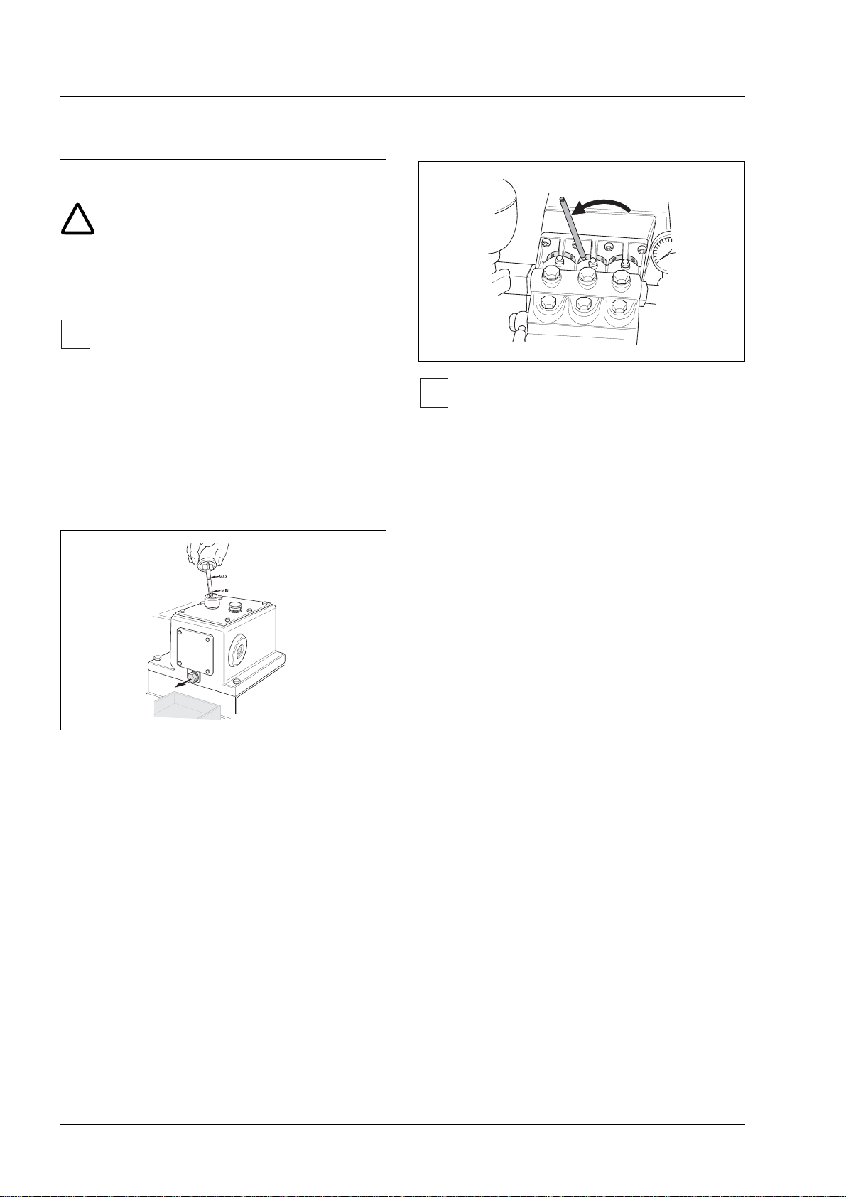
Tightening the piston seals
Important!
If the piston seal is held too tight by the
gland, it will be subjected to increased wear.
Insert rod into gland and turn in direction
indicated by arrow. This increases the
tension on the piston seal.
Tighten all three piston seals uniformly,
by turning the glands until they are handtight.
Oil change procedure:
place drip pan under pump to collect
waste oil
remove oil drain plug, and collect waste
oil in drip pan
wash out pump casing with diesel
allow diesel to drain thoroughly
fit new sealing ring (A18 x 22), and refit
oil drain plug
slowly fill up with fresh oil as far as MAX
mark
Relieving tension on piston seal:
Insert rod into gland and turn in opposite
direction to that indicated by arrow.
This relieves the tension on the piston
seal.
Relieve the tension on all three piston
seals uniformly.
deliver waste oil to an appropriate
collection point.
E4
5.956-486 A2005937 (06/03)
Page 21

SHD-R 3000
E. Care and maintenance
English
V-belt
Test tension of V-belt and adjust as follows:
Switch off system, and ensure that it
cannot be switched back on again
unintentionally.
Remove guard over V-belt.
Test belt tension.
Press down on belt which should not
move by more than 1 cm. If necessary,
adjust as follows:
Replacing the V-belt:
Switch off system, and ensure that it
cannot be switched back on again unintentionally.
Remove guard over V-belt.
Slacken off mounting bolts (1).
Unscrew bolts (2) fully, and push motor
towards pump.
Replace V-belt.
Tension belt by adjusting bolts (2).
Ensure that V-belt runs in a straight line.
Tighten mounting bolts (1).
Refit belt guard.
Slacken off mounting bolts (1).
Tension V-belt by adjusting bolts (2).
Ensure that V-belt runs in a straight line.
Tighten mounting bolts (1).
Refit belt guard.
5.956-486 A2005937 (06/03)
E5
Page 22

English
!
Danger!
Injury hazard while working on the system.
Before commencing any work:
Turn mains supply voltage off at system
master switch, and ensure that it cannot
be turned back on again unintentionally.
Turn off supply of cleaning liquid.
If a handgun is being used, release any
remaining pressure in the system by
pressing the lever on the handgun.
F . T roubleshooting
SHD-R 3000
Who is permitted to repair faults on the
system?
Operator
Tasks that are marked “Operator” may
only be carried out by persons who have
been instructed in the safe operation and
maintenance of high-pressure systems.
Qualified electrician
Persons who have a professional qualification in an electrical engineering
discipline.
Customer Service
Tasks that are marked “Customer Service”
should only be carried out by a Kärcher
Customer Service engineer.
F1
5.956-486 A2005937 (06/03)
Page 23
SHD-R 3000
F . T roubleshooting
English
1. Fault-finding
Problem Component Possible cause Remedy By whom?
System
does not
start up
System
does not
build up
pressure
Control
circuitry
Control
circuitry
Control
circuitry
Pressure
switch
(Accessory
kit)
V-belt No tension in V-belt Tighten V-belt (see Maintenance
Filter or
strainer
(Accessories)
No voltage supply to
system or control
circuitry
Fault on
– motor contactor
– fuses
Bimetal relay has
switched off
Defective or wrongly
adjusted pressure switch
Blocked filter or strainer
in supply line
Check mains voltage Electrician
Check Electrician
Wait for motor to cool down, and
then re-set relay.
Measure motor current. If
current consumption is too high,
relieve tension on piston seal
(see Maintenance Tasks).
Release pressure from system,
and check pressure valve.
Tasks)
Remove and clean filter or
strainer.
Electrician
Customer
service
Operator
Operator
Screech-
ing noise
Inlet hose Supply volume too small Test whether the correct amount
of cleaning liquid is being
supplied to system.
High-pressure
pump
High-pressure
pump
Detergent
reservoir
(Accessory
kit)
V-belt Incorrect V-belt tension Tighten V-belt (see Maintenance
Worn out valves or
broken valve spring
Defective piston, seal or
valve
Pump taking in air due
to empty detergent
container
Replace defective part. Operator
Replace defective part. Customer
Fill detergent reservoir. Operator
Tasks).
Operator
service
Operator
5.956-486 A2005937 (06/03)
F2
Page 24
English
F . T roubleshooting
SHD-R 3000
1. Fault-finding
Problem Component Possible cause Remedy By whom?
Knocking
noise
Leaking
pressure
switch
V-belt V-belt has snapped Replace V-belt (see Maintenance
Tasks)
Detergent
metering on
suction side of
pump
(Accessory
kit)
Cleaning
liquid
High-pressure
pump
High-pressure
pump
Pulsation
damper
(Accessory
kit)
Pressure
switch
(Accessory
kit)
Pump is taking in air ––Fill up with cleaning liquid.
Check hoses to establish
whether they are taking in air
Cleaning liquid is too
warm
Broken valve spring Replace valve springs Operator
Flange has come loose Tighten flange (see Maintenance
Defective pulsation
damper
Defective seal Replace seal. Customer
Check supply temperature of
cleaning liquid
Tasks)
Replace pulsation damper. Customer
Operator
Operator
Operator
Operator
service
service
Leaking
pump
System
does not
switch off
although
handgun
is closed
Float tank
overflows
High-pressure
switch
Pressure
switch/Volume
control valve
(Accessory
kit)
Float tank
(Accessory
kit)
Float tank
(Accessory
kit)
Too much free play in
piston seal
Wrongly adjusted
pressure switch or
volume control valve
Wrongly adjusted
closing force or
maximum filling level
Defective seal on float
valve
Tighten piston seal (see
Maintenance Tasks)
Re-adjust pressure switch and
volume control valve.
Re-adjust closing force and filling
level, see Chapter G1: Float
tank.
Replace seal. Operator
Operator
Customer
service
Operator
F3
5.956-486 A2005937 (06/03)
Page 25
SHD-R 3000
!
!
i
Hazard!
The following mounting and accessory kits
must not be used for operation with solvents
or in a hazardous (potentially explosive
atmosphere) area.
G. Mounting kits and accessories
1. Mounting kits
(non-hazardous area)
English
V olume control v alve
Function
If only a part of the pump delivery volume is
required, the remainder is fed back to the
suction side of the pump via the volume
control valve.
This item is required when the system is
used with handguns.
Float tank with float valve
Function
The float valve fitted inside the float tank
controls the level of liquid.
The float tank serves as a service
reservoir for the cleaning liquid.
If water is used as the cleaning agent,
the float tank corresponds to mains
disconnection according to EN 1717.
In the case of the mobile systems, the
float tank is fitted to the trolley.
Pressure switch
Danger!
Danger due to high voltage. The pressure
switch has been pre-set in the factory,
adjustments should only be made by a
Kärcher Customer Service engineer.
Function
The pressure switch
switches the system off if the working
pressure is exceeded.
switches the system back on when the
pressure drops again.
Pulsation damper
Caution!
Settings
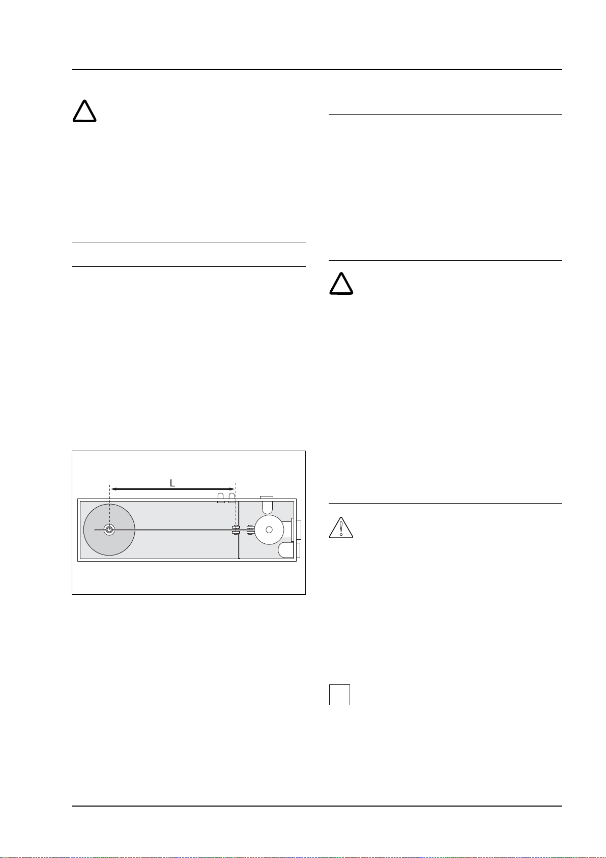
Closing force
Extending the length of L increases the
amount of closing force, i.e. even when the
cleaning liquid is fed in at quite high pressure
the float valve is able to shut off the supply.
Technical specification
Capacity up to overflow: 30 litres.
5.956-486 A2005937 (06/03)
As the membrane in the pulsation damper is
not suitable for solvents, do not use the
pulsation damper for operation with
solvents.
Function
The pulsation damper evens out variations
or peaks in pressure while the system is in
operation.
Important!
Volume control valve, pressure switch and
pulsation damper are usually employed
together as an automatic volume control
system.
G1
Page 26

English
G. Mounting kits and accessories
SHD-R 3000
Pressure-relief valve
Function
The pressure-relief valve is an integrated
solenoid valve.
The pressure-relief valve is only active
during the start-up phase when the
system is configured for star-delta
starting.
When the pressure-relief valve is opened,
the liquid delivered by the pump flows
back to the suction side. As a result, no
pressure is built up, and the load on the
motor is reduced during the start-up
phase.
Detergent metering at the suction
side of the pump
Danger!
If the detergent reservoir is empty and the
metering valve is open, the pump takes in
air. This can lead to damage to the pump,
therefore:
check detergent reservoir regularly,
do not open metering valve until actual
work commences,
close metering valve as soon as work
has ended.
Function
A diaphragm has been inserted into the
pump intake connection,
detergent is taken in from an external
reservoir,
the amount taken in is determined by a
metering valve,
metering is switched on or off by a solenoid
valve.
Detergent metering at the pressure
side of the pump
Function
Detergents are taken in from an external
reservoir and fed to the output from the
pump,
an injector mixes the detergent with the
high-pressure jet (double spray lance
required for detergent metering),
detergents can also be metered by
means of a high-pressure metering pump.
2. Mounting kits
(hazardous area)
Please contact Kärcher about mounting kits
for hazardous (potentially explosive
atmosphere) areas.
For representations, please refer to figures
A 170/1, A 172, A 173, A 161 and A 154.
3. Accessories
Lubricants:
Oil for pump: Oil 40 special
Order no. 6.288-003 (1 litre pack)
Lubricating grease for:SHD-R 3000 (F)
SHD-R 3000 (F) S/
SHD-R 3000 (F) SVA
(6.288-034)
For normal use:
Order no. 6.288-015 (Tin with 1 kg)
The following grease is prescribed for foodprocessing operations:
Order no. 6.288-034 (Tin with 1 kg)
High-pressure hoses, nozzles,
detergents
Ask your dealer for further details about
these or any other accessories, or contact
Kärcher Plant Engineering.
G2
5.956-486 A2005937 (06/03)
Page 27

SHD-R 3000
Figure A 170/1
G. Mounting kits and accessories
English
5.956-486 A2005937 (06/03)
G3
Page 28

English
Figure A 172
G. Mounting kits and accessories
SHD-R 3000
G4
5.956-486 A2005937 (06/03)
Page 29

SHD-R 3000
Figure A 173
G. Mounting kits and accessories
English
5.956-486 A2005937 (06/03)
G5
Page 30

English
Figure A 161
G. Mounting kits and accessories
SHD-R 3000
G6
5.956-486 A2005937 (06/03)
Page 31

SHD-R 3000
Figure A 154
G. Mounting kits and accessories
English
5.956-486 A2005937 (06/03)
G7
Page 32

English
The applicable warranty conditions in
different countries are issued by the
respective national distributor of KÄRCHER
products.
In the event of a warranty claim, please
contact your original dealer or the nearest
authorized customer service centre.
H. W arranty
SHD-R 3000
H1
5.956-486 A2005937 (06/03)
Page 33

SHD-R 3000
!
I. System installation
English
This system should only be installed by
Kärcher Customer Service engineers,
persons who have been specially
authorized by Kärcher.
Unpacking the system
Unpack the system and deliver the packaging materials to an appropriate collection
point for recycling.
For static systems
Preparing the installation site
A horizontal, flat area or base of 1400 x
750 mm is required for installing the
system.
Place the system on the designated area
or base and align it exactly.
Check the oil level
The level of oil in the reservoir on the highpressure pump should be between the MIN
and MAX marks. Fill up with oil if the level
is below the MIN mark.
Electrical connections
Danger!
Dangerous voltage. The electrical installation
should only be carried out by a qualified
electrician in accordance with current local
regulations.
Connect the electric motor into the
terminal strip.
Switch on motor briefly, and check
direction of rotation.
Install the unit in such a way as to ensure
that it can be easily accessed for
maintenance work.
Secure in position with suitable materials.
For static and mobile systems
Connecting hoses for supply
of cleaning liquid
Caution!
Vibrations generated by the system during
operation could cause damage to the main
water supply network, therefore connect the
system by means of flexible hoses.
Connect the supply hose for cleaning
liquid to the system (Thread R 1 1/4").
Connect the high-pressure hose for the
cleaning liquid output to the system
(Thread M22 x 1.5).
Start up the system
Switching off in an emergency
(see Chapter B)
5.956-486 A2005937 (06/03)
I1
Page 34

English
Dimensional diagram:
Static system
Mobile system
I. System installation
SHD-R 3000
approx. 1100
I2
5.956-486 A2005937 (06/03)
Page 35
SHD-R 3000
J. Declaration of Conformity
EC Declaration of Conformity
English
We herewith declare that the design and
type of machine named in the following as
well as the model marketed by us complies
with the relevant fundamental health and
safety requirements of the EC Directives.
This declaration becomes invalid if
modifications are made to the machine
which have not been previously agreed with
us.
Product: High-pressure cleaner
Type: SHD-R 3000 (F), S, SVA
Relevant EC Directives:
EC Machinery Directive (98/37/EC)
EC Low Voltage Directive (73/23/EEC),
amended by 93/68/EEC
EC Electromagnetic Compatibility
Directive (89/336/EEC), amended by
91/263/EEC, 92/31/EEC, 93/68/EEC
Alfred Kärcher GmbH & Co. KG
Cleaning Systems
Alfred-Kärcher-Str. 28-40
P.O. Box 160
D-71349 Winnenden
Tel.: ++ 49 71 95 14-0
Fax: ++ 49 71 95 14-22 12
5.957-383 (01/02)
Alfred Kärcher Kommanditgesellschaft.
Registered offices: Winnenden.
Register court: Waiblingen, HRA 169.
Personally liable shareholder: Kärcher
Reinigungstechnik GmbH.
Registered office: Winnenden, 2404
Waiblingen register court, HRB
Managing Directors: Dr. Bernhard Graf,
Hartmut Jenner, Georg Metz
Harmonised standards used:
DIN EN 60 335 - 1
DIN EN 60 335 - 2 - 79
DIN EN 55 014 - 1:2000 + A1 : 2001
DIN EN 55 014 - 2 : 1997
DIN EN 61 000 - 3 - 2 : 2000
DIN EN 61 000 - 3 - 3 : 1995 + A1 : 2001
National standards used: –
Internal measures ensure that serial
production units always comply with the
requirements of the current EC Directives
and the standards used.
The undersigned act on behalf of and with
power of attorney issued by the
Management.
S. Reiser H. Jenner
5.956-486 A2005937 (06/03)
J1
Page 36
English
J. Declaration of Conformity
EC Declaration of Conformity
SHD-R 3000
We herewith declare that the design and
type of machine named in the following as
well as the model marketed by us complies
with the relevant fundamental health and
safety requirements of the EC Directives.
This declaration becomes invalid if
modifications are made to the machine
which have not been previously agreed with
us.
Product: High-pressure cleaner
Type: SHD-R 3000 (F), LM, SSR, SLA
Relevant EC Directives:
EC Machinery Directive (98/37/EC)
EC ATEX Directive (94/9/EC)
Harmonised standards used:
DIN EN 60 335 - 1
DIN EN 60 335 - 79
Alfred Kärcher GmbH & Co. KG
Cleaning Systems
Alfred-Kärcher-Str. 28-40
P.O. Box 160
D-71349 Winnenden
Tel.: ++ 49 71 95 14-0
Fax: ++ 49 71 95 14-22 12
5.957-384 (06/03)
Alfred Kärcher Kommanditgesellschaft.
Registered office: Winnenden.
Register court: Waiblingen, HRA 169.
Personally liable shareholder:
Kärcher Reinigungstechnik GmbH.
Registered office: Winnenden, 2404
Waiblingen register court, HRB
Managing Directors: Dr. Bernhard Graf,
Hartmut Jenner, Georg Metz
DIN EN 13463 - 1 : 2002
prEN 13463 - 5 : 2002
EN 1127 - 1 : 1997
National standards used: –
No. of nominated test institute: 0123
Test report No. 070039582
Type LM designation: Ex II 2 G ck T4
Type SSR, SLA designation: Ex II 2 G ck T3
Internal measures ensure that serial
production units always comply with the
requirements of the current EC Directives
and the standards used.
The undersigned act on behalf of and with
power of attorney issued by the
Management.
S. Reiser H. Jenner
J2
5.956-486 A2005937 (06/03)
Page 37
SHD-R 3000
Type no.: Factory no.: Commissioned on:
Tests carr ied out on:
..............................................................................................................
Results
Tests carr ied out on:
..............................................................................................................
Results
K. T est record
.......................................
Signature
English
Tests carr ied out on:
..............................................................................................................
Results
Tests carr ied out on:
..............................................................................................................
Results
.......................................
Signature
.......................................
Signature
5.956-486 A2005937 (06/03)
.......................................
Signature
K1
 Loading...