


OPERATOR'S MANUAL
ENGLISH
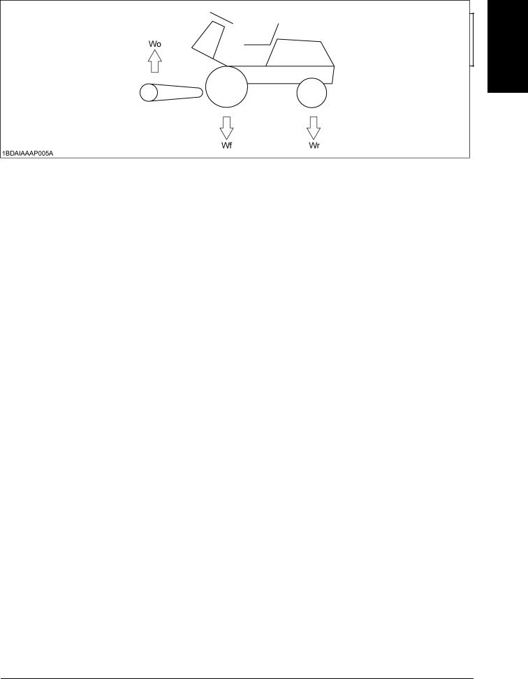
MODELS F2690E
F2690
F3990
K3615-6296-2
1BDAIAYAP0010
READ AND SAVE THIS MANUAL
ENGLISH
ABBREVIATION LIST
Abbreviations |
Definitions |
|
|
2WD |
2 Wheel Drive |
4WD |
4 Wheel Drive |
API |
American Petroleum Institute |
ASABE |
American Society of Agricultural and Biological Engineers, USA |
ASTM |
American Society for Testing and Materials, USA |
DIN |
Deutsches Institut für Normung, GERMANY |
DT |
Dual Traction [4WD] |
fpm |
Feet Per Minute |
GST |
Glide Shift Transmission |
T/M |
Transmission |
Hi-Lo |
High Speed-Low Speed |
HST |
Hydrostatic Transmission |
m/s |
Meters Per Second |
PTO |
Power Take Off |
RH/LH |
Right-hand and left-hand sides are determined by facing in |
|
the direction of forward travel |
F&R |
Front and rear sides are determined by facing in the |
|
direction of forward travel |
ROPS |
Roll-Over Protective Structures |
rpm |
Revolutions Per Minute |
r/s |
Revolutions Per Second |
SAE |
Society of Automotive Engineers, USA |
SMV |
Slow Moving Vehicle |
SPT |
Semi-Permanent Type |
|
|
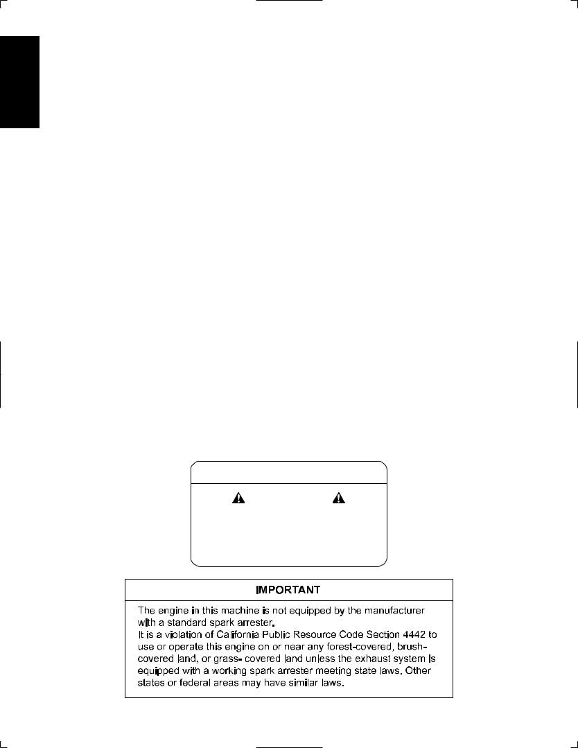
California Proposition 65
WARNING
Engine exhaust, some of its constituents, certain vehicle components and fluids, contain or emit chemicals known to the State of California to cause cancer and birth defects or other reproductive harm.
The above ''IMPORTANT'' text for the spark arrester is applicable to Model F2690E, F2690 alone.
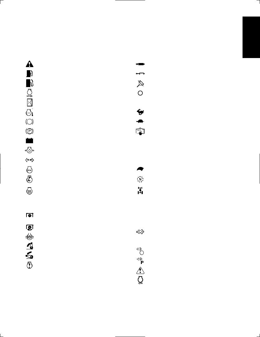
UNIVERSAL SYMBOLS
As a guide to the operation of your machine, various universal symbols have been utilized on the instruments panels and controls. The symbols are shown below with an indication of their meaning.
Safety Alert Symbol |
|
|
|
|
Remote Cylinder-Retract |
|
Diesel Fuel |
|
|
|
|
Remote Cylinder-Extend |
|
Fuel-Level |
|
|
|
|
Steering Wheel-Tilt Control |
|
Engine-Rotational Speed |
|
|
|
|
Head Lights OFF |
|
Hourmeter/Elapsed Operating Hours |
|
|
|
|
Head Lights ON |
|
Engine Coolant-Temperature |
|
|
|
|
Fast |
|
Brake |
|
|
|
|
Slow |
|
Parking Brake |
|
|
|
|
Read Operator's Manual |
|
Battery Charging Condition |
|
|
|
|
Machine-Forward Movement-Overhead View |
|
Engine Oil-Pressure |
|
|
|
|
of Machine |
|
|
|
|
|
Machine-Rearward Movement-Overhead View |
||
|
|
|
|
|
|
|
Turn Signal |
|
|
|
|
of Machine |
|
Engine-Stop |
|
|
|
|
Engine Speed Control |
|
Engine-Run |
|
|
|
|
Neutral |
|
Diesel Preheat/Glow Plugs (Low Temperature |
|
|
|
|
Full Time 4WD |
|
Start Aid) |
|
|
|
|
This position provides 4WD machanically in |
|
Starter Control |
|
|
|
|
any kind of the ground condition. |
|
|
|
|
|
Dual-Acting Overrunning 4WD |
||
|
|
|
|
|
|
|
Power Take-Off Control-Off Position |
|
|
|
|
This position provides 4WD autmatically only |
|
(Disengaged) |
|
|
|
|
when the ground speed dictate between front |
|
Power Take-Off Control-On Position (Engaged) |
|
|
|
|
and rear wheels (forward and backward). |
|
|
|
|
|
Regeneration |
||
Differential Lock |
|
|
|
|
||
|
|
|
|
DPF INHIBIT (Switch) |
||
Position Control-Raised Position |
|
|
|
|
|
|
|
|
|
|
|
Regeneration (Switch) |
|
|
|
|
|
|
|
|
Position Control-Lowered Position |
|
|
|
|||
|
|
|
|
|||
|
|
|
|
Parked Regeneration |
||
Engine Warning |
|
|
|
|
||
|
|
|
||||
|
|
|
|
Master System Warning |
||
|
|
|
|
|
|
|
|
|
|
|
|
|
Constant RPM Management |
ENGLISH

ENGLISH
FOREWORD
You are now the proud owner of a KUBOTA FRONT MOWER. This machine is a product of KUBOTA's quality engineering and manufacturing. It is made of excellent materials and under a rigid quality control system. It will give you long, satisfactory service. To obtain the best use of your machine, please read this manual carefully. It will help you become familiar with the operation of the machine and contains many helpful hints about machine maintenance. It is KUBOTA's policy to utilize, as quickly as possible, every advance in our research. The immediate use of new techniques in the manufacturing of products may cause some small parts of this manual to become outdated. KUBOTA distributors and dealers will have the most up-to-date information. Please do not hesitate to consult them.
3SAFETY FIRST
This symbol, the industry's ''Safety Alert Symbol'', is used throughout this manual and on labels on the machine itself to warn of the possibility of personal injury. Read these instructions carefully. It is essential that you read the instructions and safety regulations before you attempt to assemble or use this unit.
3DANGER : Indicates an imminently hazardous situation which, if not avoided, will result in death or serious injury.
3WARNING : Indicates a potentially hazardous situation which, if not avoided, could result in death or serious injury.
3CAUTION : Indicates a potentially hazardous situation which, if not avoided, could result in minor or moderate injury.
IMPORTANT : Indicates that equipment or property damage could result if instructions are not followed.
NOTE : Gives helpful information.
MANUAL DEL OPERADOR
MODELOS F2690E
F2690
F3990
ESPAÑOL
1BDAIAYAP0010
LEA Y CONSERVE ESTE MANUAL

CONTENTS |
|
SAFE OPERATION ............................................................................................ |
-1 |
SERVICING OF MACHINE ......................................................................................... |
1 |
SPECIFICATIONS....................................................................................................... |
3 |
IMPLEMENT LIMITATIONS ........................................................................................ |
5 |
INSTRUMENT PANEL AND CONTROLS................................................................... |
6 |
MOWER MOUNTING .................................................................................................. |
7 |
MOUNTING THE MOWER ...................................................................................... |
7 |
DISMOUNTING THE MOWER DECK ..................................................................... |
8 |
MOWER TILT UP..................................................................................................... |
8 |
How To Tilt Up.................................................................................................................. |
8 |
How To Mount Another Implement................................................................................... |
8 |
PRE-OPERATION CHECK ......................................................................................... |
9 |
DAILY CHECK ......................................................................................................... |
9 |
OPERATING THE ENGINE....................................................................................... |
10 |
EXHAUST AFTERTREATMENT DEVICES........................................................... |
10 |
Diesel Oxidation Catalyst and Diesel Particulate Filter (DPF) Muffler ............................ |
10 |
Handling Points............................................................................................................... |
11 |
DPF Regeneration Process............................................................................................ |
11 |
Auto Regeneration Operating Procedure ....................................................................... |
12 |
PM Warning Level and Required Procedures ................................................................ |
13 |
Regeneration Inhibit Mode Operating Procedure ........................................................... |
14 |
PM Warning Level and Required Procedures ................................................................ |
15 |
Tips on DPF Regeneration ............................................................................................. |
17 |
Handling at low temperature........................................................................................... |
17 |
STARTING THE ENGINE ...................................................................................... |
18 |
Key Switch...................................................................................................................... |
20 |
Cold Weather Starting .................................................................................................... |
20 |
Block Heater (Option) ..................................................................................................... |
20 |
STOPPING THE ENGINE...................................................................................... |
21 |
WARMING UP ....................................................................................................... |
21 |
Warm-up and Transmission Oil in the Low Temperature Range.................................... |
21 |
Engine Stop Lever and Fuel Valve (Inside the Hood)..................................................... |
21 |
JUMP STARTING .................................................................................................. |
22 |
OPERATING THE MACHINE.................................................................................... |
23 |
OPERATING NEW MACHINE ............................................................................... |
23 |
Changing Lubricating Oil for New Machines................................................................... |
23 |
Engine Break-in .............................................................................................................. |
23 |
Machine Break-in............................................................................................................ |
23 |
OPERATING FOLDABLE ROPS ........................................................................... |
24 |
ENGLISH
To Fold the ROPS .......................................................................................................... |
24 |
To Raise the ROPS to Upright Position.......................................................................... |
25 |
Adjustment of Foldable ROPS........................................................................................ |
25 |

ENGLISH
CONTENTS |
|
STARTING ............................................................................................................. |
26 |
Operator's Seat............................................................................................................... |
26 |
Globe Box....................................................................................................................... |
26 |
Steering Wheel Tilt Lever ............................................................................................... |
27 |
Seat Belt ......................................................................................................................... |
27 |
Head Light Switch........................................................................................................... |
27 |
Lift Link Lowering Speed Control Knob .......................................................................... |
28 |
Hydraulic Lift Lever......................................................................................................... |
28 |
High-Low Gear Shift Lever ............................................................................................. |
29 |
4WD Lock Lever ............................................................................................................. |
29 |
PTO Lever ...................................................................................................................... |
30 |
Throttle Lever.................................................................................................................. |
30 |
Parking Brake ................................................................................................................. |
30 |
Speed Control Pedal....................................................................................................... |
31 |
Differential Lock Pedal.................................................................................................... |
31 |
STOPPING............................................................................................................. |
31 |
Stopping.......................................................................................................................... |
31 |
CHECK DURING DRIVING ................................................................................... |
32 |
Immediately Stop the Engine if:...................................................................................... |
32 |
Easy Checker (TM)......................................................................................................... |
32 |
LCD MONITOR ...................................................................................................... |
33 |
Fuel Gauge..................................................................................................................... |
33 |
Coolant Temperature Gauge.......................................................................................... |
34 |
Hourmeter / Tachometer................................................................................................. |
34 |
Service Code Display ..................................................................................................... |
35 |
Overheat Alarm............................................................................................................... |
35 |
ELECTRONIC ENGINE CONTROL....................................................................... |
35 |
Constant RPM Management Control.............................................................................. |
35 |
PARKING............................................................................................................... |
36 |
Parking............................................................................................................................ |
36 |
TRANSPORTING................................................................................................... |
36 |
Directions for Use of Power Steering.............................................................................. |
36 |
TIRES, WHEELS AND BALLAST.............................................................................. |
37 |
TIRES..................................................................................................................... |
37 |
Inflation Pressure............................................................................................................ |
37 |
WHEELS ................................................................................................................ |
37 |
Front Wheels (Drive Wheels).......................................................................................... |
37 |
Rear Wheels (Steering Wheels) ..................................................................................... |
38 |
BALLAST ............................................................................................................... |
38 |
MAINTENANCE......................................................................................................... |
39 |
SERVICE INTERVALS .......................................................................................... |
39 |
PERIODIC SERVICE CHART LABEL ................................................................... |
42 |
LUBRICANTS, FUEL AND COOLANT .................................................................. |
43 |
PERIODIC SERVICE................................................................................................. |
45 |
HOW TO OPEN THE HOOD ................................................................................. |
45 |
DAILY CHECK ....................................................................................................... |
46 |
Checking Seat Belt and ROPS....................................................................................... |
46 |
Checking Engine Oil Level.............................................................................................. |
47 |
Checking Amount of Fuel and Refueling ........................................................................ |
48 |

|
CONTENTS |
Checking and Cleaning Radiator Screen and Bonnet Screen to Prevent Overheating.. 49 |
|
Checking Tire Pressure .................................................................................................. |
50 |
Checking Transmission Fluid Level................................................................................ |
51 |
Checking Coolant Level.................................................................................................. |
51 |
Checking DPF Muffler..................................................................................................... |
52 |
Checking Movable Parts................................................................................................. |
52 |
EVERY 50 HOURS ................................................................................................ |
53 |
Checking Engine Start System....................................................................................... |
53 |
Checking OPC System................................................................................................... |
54 |
Lubricating All Grease Fittings........................................................................................ |
54 |
Oiling............................................................................................................................... |
56 |
Checking Wheel Bolt Torque.......................................................................................... |
57 |
EVERY 100 HOURS .............................................................................................. |
57 |
Checking Battery Condition ............................................................................................ |
57 |
Cleaning Air Cleaner Element ........................................................................................ |
59 |
Checking Fuel Filter........................................................................................................ |
60 |
Checking and Adjusting Brake Pedal ............................................................................. |
61 |
Checking Fan Drive Belt Tension ................................................................................... |
62 |
EVERY 200 HOURS .............................................................................................. |
62 |
Changing Engine Oil....................................................................................................... |
62 |
Replacing Engine Oil Filter Cartridge ............................................................................. |
63 |
Replacing Transmission Oil Filter Cartridge ................................................................... |
64 |
EVERY 400 HOURS .............................................................................................. |
64 |
Changing Transmission Fluid ......................................................................................... |
64 |
Cleaning Transmission Strainer...................................................................................... |
65 |
Changing Rear Axle Differential Case Fluid [4WD] ........................................................ |
66 |
Changing Rear Axle Gear Case Fluid [4WD] ................................................................. |
66 |
Adjusting Rear Axle Pivot ............................................................................................... |
67 |
Replacing Fuel Filter....................................................................................................... |
67 |
EVERY 800 HOURS .............................................................................................. |
67 |
Adjusting Engine Valve Clearance ................................................................................. |
67 |
EVERY 1000 HOURS or EVERY 1 YEAR............................................................. |
67 |
Replacing Air Cleaner Primary Element and Secondary Element.................................. |
67 |
Checking Exhaust manifold ............................................................................................ |
67 |
EVERY 1500 HOURS ............................................................................................ |
67 |
Checking Fuel Injection Nozzle (Injection Pressure) ...................................................... |
67 |
EVERY 2000 HOURS or EVERY 2 YEARS .......................................................... |
68 |
Flush Cooling System and Changing Coolant................................................................ |
68 |
Anti-freeze ...................................................................................................................... |
69 |
EVERY 3000 HOURS ............................................................................................ |
70 |
Checking Turbo Charger ................................................................................................ |
70 |
Checking Injection Pump................................................................................................ |
70 |
EVERY 1 YEAR ..................................................................................................... |
70 |
Checking Radiator Hose and Clamp .............................................................................. |
70 |
Checking Hydraulic Hose ............................................................................................... |
71 |
Checking Fuel Lines ....................................................................................................... |
71 |
Checking Intake Air Line................................................................................................. |
72 |
Checking Engine Breather Hose .................................................................................... |
72 |
EVERY 4 YEARS................................................................................................... |
72 |
ENGLISH
Replacing Hydraulic Hose .............................................................................................. |
72 |
Replacing Fuel Lines ...................................................................................................... |
72 |
Replacing Engine Breather Hose ................................................................................... |
72 |

ENGLISH
CONTENTS |
|
Replacing Radiator Hose................................................................................................ |
72 |
Replacing Intake Air Line................................................................................................ |
72 |
SERVICE AS REQUIRED...................................................................................... |
73 |
Replacing Fuses............................................................................................................. |
73 |
Replacing Light Bulb....................................................................................................... |
74 |
Bleeding Fuel System..................................................................................................... |
74 |
Adjusting Lift Springs (LH & RH) .................................................................................... |
75 |
STORAGE ................................................................................................................. |
76 |
TROUBLESHOOTING............................................................................................... |
77 |
ENGINE TROUBLESHOOTING ............................................................................ |
77 |
POWER TRAIN TROUBLE SHOOTING................................................................ |
78 |
BATTERY TROUBLESHOOTING ......................................................................... |
79 |
MACHINE TROUBLESHOOTING ......................................................................... |
80 |
INDEX........................................................................................................................ |
81 |

SAFE OPERATION  -1
-1
SAFE OPERATION
Careful operation is your best insurance against an accident. Read and understand this section carefully before operation. All operators, no matter how experienced they may be, should read this and other related manuals before operation of the machine or any implement attached to it. It is the owner's obligation to instruct all operators in safe operation.
This cutting machine is capable of amputating hands and feet and throwing objects. Failure to observe the following safety instructions could result in serious injury or death.
1.BEFORE OPERATING
1.Know your equipment and its limitations. Read, understand and follow all instructions in this manual before attempting to start and operate the machine.
2.Pay special attention to the safety labels on the machine and mower.
3.KUBOTA recommends the use of a Roll Over Protective Structures (ROPS) and seat belt in almost all applications. This combination will reduce the risk of serious injury or death, should the machine be upset.
The machine is equipped with a foldable ROPS, which may be temporarily folded down only when absolutely necessary for areas with height constraints.
(There is no operator protection provided by the ROPS in the folded position. For operator safety the ROPS should be placed in the upright and locked position and the seat belt fastened for all other operations.)
If the ROPS is loosened or removed for any reason, make sure that all parts are reinstalled correctly before operating the machine.
Never modify or repair a ROPS because welding, bending, drilling, grinding, or cutting may weaken the structure.
A damaged ROPS structure must be replaced, not repaired or revised.
If any structural member of the ROPS is damaged, replace the entire structure at your local KUBOTA Dealer.
(1)ROPS
(2)Seat belt
4.Always use the seat belt when the ROPS is upright. Do not use the seat belt without a ROPS being upright. Check the seat belt regularly and replace if frayed or damaged.
5.The exhaust gas from the muffler is very hot. To prevent fire, do not expose dry grass, mowed grass, oil or any other combustible materials to exhaust gas. Use a spark arrester where required. Also keep the engine and muffler clean all the time. Replace the muffler if it has a fault.
6.Never wear loose, torn, or bulky clothing. It may catch on moving parts or controls, leading to the risk of accident. Safety boots or shoes, eye and hearing protection, gloves, dust mask, etc. are recommended.
7.Do not wear radio or music headphones while operating the machine.
Safe operation requires your full attention.
8.Carefully check the vicinity before operating machine or any implement attached to it. Clear the work area of objects (wires, rocks, etc.) that might be picked up and thrown. Check for overhead clearance which may interfere with a ROPS.
9.Do not operate machine or any implement attached to it while under the influence of alcohol, drugs, or other substances or while fatigued.
10.Check brakes, and other mechanical parts for faulty adjustment and wear. Replace worn or damaged parts promptly. Check the tightness of all nuts and bolts regularly. (For further details, see "MAINTENANCE" section.)
ENGLISH
ENGLISH
 -2 SAFE OPERATION
11.Keep the machine and attachments in good operating condition and keep safety devices in place and in proper working condition.
12.Do not modify the machine. Unauthorized modification may affect the function of the machine, which may result in personal injury.
13.Keep all shields and guards in place. Replace all missing or damaged items for your safety.
14.Never allow any bystanders around or near machine during operation.
Be sure the area is clear of other people before mowing.
Stop machine if anyone enters the area.
15.Before allowing other people to use your machine, explain proper operation to them and have them read this manual before operation.
16.Never allow passengers or non-qualified operators on the machine at any time. You must operate the machine from the seat only.
17.In addition to the design and configuration of equipment, hazard control and accident prevention are dependent on the awareness, concern, and prudence of personnel involved in the operation, transport, maintenance of facilities.
18.Keep your machine clean. Dirt, grease, and trash accumulations may contribute to fires or lead to personal injury.
19.Use only attachments recommended by KUBOTA. Use proper ballast to front or rear of machine to reduce the risk of upsets. Follow the "Safe Operation" procedures, specified in the Equipment's Manual.
2.OPERATING
C Starting
1.Never start the engine or operate levers from anywhere other than the seat.
2.Before starting the engine make sure that all levers and speed control pedal are in neutral, the parking brake is engaged, and Power Take Off (PTO) is disengaged.
Fasten the seat belt if the ROPS is upright.
3.Do not start the engine while tilting the deck.
4.Do not start the engine by shorting across starter terminals or by bypassing the safety start switch. The machine may start and move if normal starting circuitry is bypassed.
5.Do not operate or idle engine in a poorly ventilated area. Exhaust gas contains carbon monoxide, a colorless, odorless gas they can be poisonous if not properly ventilated.
C Working
1.Watch where you are going at all times. Watch for and avoid obstacles. Be alert near trees and other obstructions.
2.To avoid tip over, slow down when turning on uneven terrain or before stopping.
3.Park the machine on a firm, level surface.
4.Do not drive at high speeds or turn the machine when the differential is locked.
5.Know what is behind you before backing up. Look to the rear before and while backing up. Do not mow while in reverse unless absolutely necessary and make sure the area immediately behind you is clear of obstructions or holes and small children. Use extra caution when the machine is equipped with the grass catcher. Your view to the rear is restricted.
6.When working in groups, always let others know what you are doing ahead of time.
7.Do not drive the machine on streets or highways. Watch for traffic when you cross roads or operate near roads.
8.Be aware of the mower discharge direction and do not point it at anyone.
9.When using any attachments, never direct discharge material toward bystanders. Do not allow anyone near the attachments while in operation.
Do not mow when bystanders are present in the mowing area.
10.To reduce fire hazards, keep the engine exhaust area free of debris.
11.Be sure rotating blades and engine are stopped and the key is removed before placing hands or feet near blades and cleaning blockages or unclogging chute.
12.Shut the engine off and wait for all movement to stop before unclogging the chute of the grass catcher. [if equipped]
13.Always inspect the mower and the grass catcher [if equipped] after striking any foreign object. This will insure that all mower and grass catcher parts are safe and secure and not damaged.
Repair or replace any damaged parts before restarting.
14.Operate during daylight or in bright artificial light.
15.Do not operate where machine could tip or slip.
Do not operate near ditches, holes, embankments, or other terrain which may collapse under the machine's weight. The risk of machine tip-over is increased when the ground is loose or wet.
C Operation on slopes
Slopes are a major factor related to loss-of-control and tipover accidents, which can result in severe injury or death. All slopes require extra caution. If you cannot back up the slope or if you feel uneasy on it, do not mow it.
A Do not lift the grass container on a slope. [if equipped]

SAFE OPERATION  -3
-3
DO
1.To avoid tip over, operate up and down slowly, not across. Stay off hills and slopes too steep for safe operation.
2.Remove obstacles such as rocks, tree limbs, etc.
3.Stay alert for holes in the terrain and other hidden hazards. Keep away from drop-offs. Uneven terrain could overturn the machine. Tall grass can hide obstacles.
4.Follow KUBOTA's recommendations for wheel weights or counterweights to improve stability.
5.The weight of grass in the grass container may increase the possibility of tip over. [if equipped]
6.Keep all movement on slopes slow and gradual. Do not make sudden changes in speed or direction.
7.Avoid starting or stopping on a slope. If tires lose traction, disengage the blades and proceed slowly straight down the slope.
8.Reduce speed and exercise extreme caution on slopes and in sharp turns to prevent tip-over or loss of control.
9.Use special caution when changing direction on slopes.
10.Shift "High - Low Gear Shift Lever" to the Low position when mowing or operating on slopes.
DO NOT
1.Do not turn on slopes unless necessary and then turn slowly and gradually downhill, if possible.
2.Do not mow near drop-offs, ditches, or embankments. The machine could suddenly turn over if a wheel falls over the edge of a cliff or ditch, or if an edge caves in.
3.Do not mow on wet grass. Reduced traction could cause sliding.
4.Do not try to stabilize the machine by putting your foot on the ground.
5.Do not use the grass catcher on steep slopes. [if equipped]
6.Do not stop or start suddenly when going uphill or downhill.
7.Never "freewheel". Do not let the machine travel downhill with HST pedal at neutral position.
C Children
Tragic accidents can occur if the operator is not alert to the presence of children. Children are attracted to the machine and the mowing activity. Never assume that children will remain where you last saw them.
1.Keep children out of the mowing area and under the watchful care of another responsible adult.
2.Be alert and turn the machine off if children enter the area.
3.Before and when backing, look behind and down for small children.
4.Never carry children. They may fall off and be seriously injured or interfere with safe machine operation.
5.Never allow children to operate the machine, even under adult supervision. Local regulation can restrict the age of the operator.
6.Use extra care when approaching blind corners, shrubs, trees, or other obstructions that might hide children from sight.
C Operators, age 60 years and above
Data indicates that operators, age 60 years and above, are involved in a large percentage of machine-related injuries. These operators should evaluate their ability to operate the machine safely enough to protect themselves and others from serious injury.
C Stopping
1.Make sure that the machine and all attachments have come to complete stop before dismounting.
2.Before dismounting, disengage the PTO, lower all implements, place all control levers in their neutral positions, apply parking brake, turn off the engine and remove the key.
3.Do not park the machine on a steep incline. Park on relatively flat areas.
3.USING THE PTO
1.Before installing or using PTO-driven equipment, read the manufacturer's manual and review the safety labels attached to the equipment.
2.Wait until all moving components have completely stopped before connecting, disconnecting, adjusting, cleaning, or servicing any PTO-driven equipment.
3.Use the PTO with KUBOTA approved attachments. The speed of the PTO:
F2690E, F2690 2545 rpm at 3000 engine rpm F3990 2583 rpm at 2500 engine rpm
ENGLISH

ENGLISH
 -4 SAFE OPERATION
4. USING THE LIFT LINK |
6. SERVICING |
1.Use lift link only with authorized attachments designed for lift link usage.
2.When using a lift link mounted attachment, be sure to install the adequate counter ballast weight specified in the attachment's manual.
3.When moving the machine a long distance, set the implement lowering control in the "LOCK" position to hold the implement in the raised position.
4.Do not turn the knob quickly.
1.Before servicing the machine, park the machine on a firm, level surface, set the parking brake, stop the engine and remove the key.
2.Allow the machine to cool off before servicing the engine, muffler, etc.
3.Always stop the engine before refueling. Avoid spills and overfilling. Wipe up spilled fuel immediately.
(1) Lift link lowering speed control knob
(A)"FAST": Turn counterclockwise slowly
(B)"SLOW": Turn clockwise
(C)"LOCK": Turn clockwise to the end
5.TRANSPORTING
1.Disengage power to attachment(s) when transporting or not in use.
2.Do not tow this machine. Use a suitable truck or trailer when transporting on public roads.
3.It is recommended that this machine not be used on public roads.
4.Use extra care when loading or unloading the machine into a trailer or truck.
5.Keep attachment(s) low when transporting.
6.Move very slowly when attachment is removed.
(1)Fuel tank cap
4.Use extra care in handling diesel fuel.
(1)Use only an approved container.
(2)Do not remove fuel cap or refuel with the engine running. Allow engine to cool before refueling. Do not smoke while refueling or when standing near fuel.
(3)Do not refuel the machine indoors and always clean up spilled fuel or oil.
(4)Do not store the machine or fuel container inside where there is an open flame, such as a water heater.
5.Do not smoke when working around the battery. Keep all sparks and flames away from battery. The battery presents an explosion hazard because it gives off hydrogen and oxygen...especially when recharging.
6.Before "JUMP STARTING" a dead battery, read and follow all of the instructions to help protect the alternator from damage due to extreme load changes. (See "JUMP STARTING" in "OPERATING THE ENGINE" section.)
Batteries contain sulfuric acid and produce explosive gases. Follow the instructions below to prevent personal injury.
A Wear eye and skin protection. A Keep sparks and flame away.
A Always have adequate ventilation while charging or using the battery.
7.Keep first aid kit and fire extinguisher available at all times.

SAFE OPERATION  -5
-5
8.Disconnect the battery's negative (-) cable before working on or near electric components.
9.Do not use or charge the refillable type battery if the fluid level is below the LOWER (lower limit level) mark. Otherwise, the battery component parts may prematurely deteriorate, which may shorten the battery's service life or cause an explosion. Check the fluid level regularly and add distilled water as required so that the fluid level is between the UPPER and LOWER levels.
10.To avoid sparks from an accidental short circuit, always disconnect the battery's negative (-) cable first and connect it last.
(1)Battery
(2)Positive cable (+)
(3)Negative cable (-)
11.Do not remove the radiator cap while coolant is hot. When cool, slowly rotate cap to the first stop and allow sufficient time for excess pressure to escape before removing the cap completely. If the machine has a coolant recovery tank, add coolant there instead of the radiator.
12.Provide adequate support when changing wheels or the wheel.
13.Make sure that wheel nuts have been tightened to the specified torque.
14.Do not attempt to mount a tire on a rim. This should be done by a qualified person with the proper equipment.
15.Always maintain the correct tire inflation pressure. Do not inflate tires above the recommended pressure shown in the Operator's Manual.
16.Securely support the machine when changing wheels.
17.Make sure that wheel bolts have been tightened to the specified torque.
18.Escaping hydraulic fluid under pressure has sufficient force to penetrate the skin causing serious personal injury. Before disconnecting lines, be sure to relieve all pressure. Before applying pressure to the system, make sure all connections are tight and that lines, pipes, and hoses are not damaged.
ENGLISH
|
|
-6 SAFE OPERATION |
ENGLISH |
|
|
|
|
|
|
eye protection. |
|
|
|
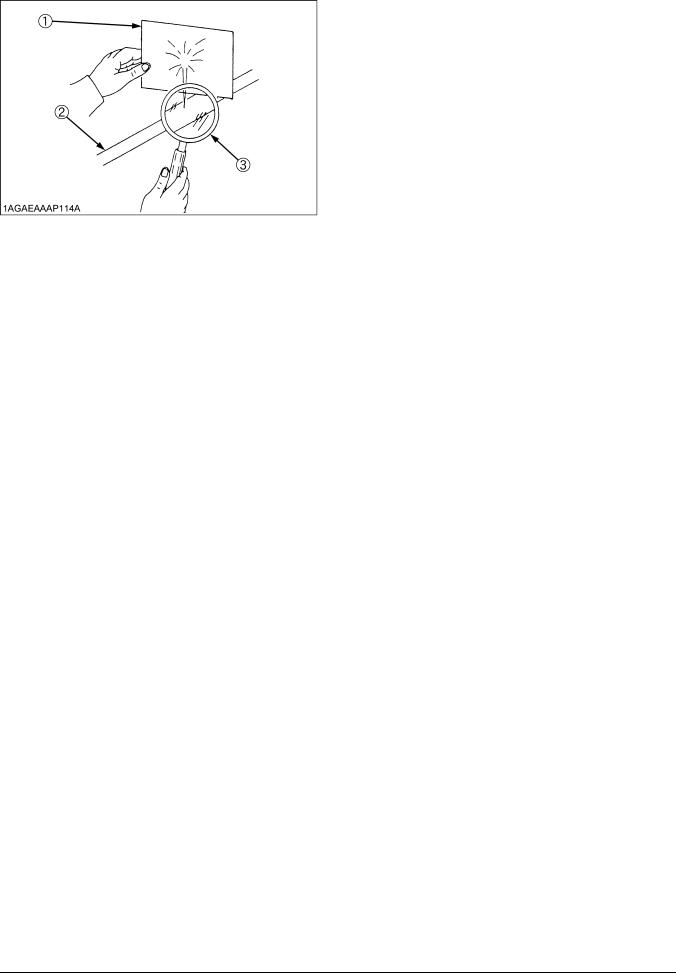
19.Fluid escaping from pinholes may be invisible. Use a |
|
|
piece of cardboard or wood to search for suspected |
|
|
leaks: do not use hands. Use safety goggles or other |
|
|
If injured by escaping fluid, see a medical doctor at |
|
|
once. Serious infection or reaction will result if proper |
|
|
|
|
|
medical treatment is not administered immediately. |
|
|
This fluid can produce gangrene or severe allergic |
|
|
reaction. |
(1)Cardboard
(2)Hydraulic line
(3)Magnifying glass
20.Do not make adjustments or repairs with the engine running.
21.Keep machine free of grass, leaves, or other debris build-up.
22.Do not run a machine inside a closed area.
7.STORAGE
1.Keep the machine and fuel supply in a secure area and remove the key to prevent children or others from playing or tampering with them.
2.Do not store the machine in an area that may ignite fuel vapor. Allow the engine to cool before storing.
3.To avoid the danger of exhaust fume poisoning, do not operate the engine in a closed building without adequate ventilation.
4.To reduce fire hazards, clean the machine thoroughly before storage. Dry grass and leaves around the engine and mufflers may ignite.
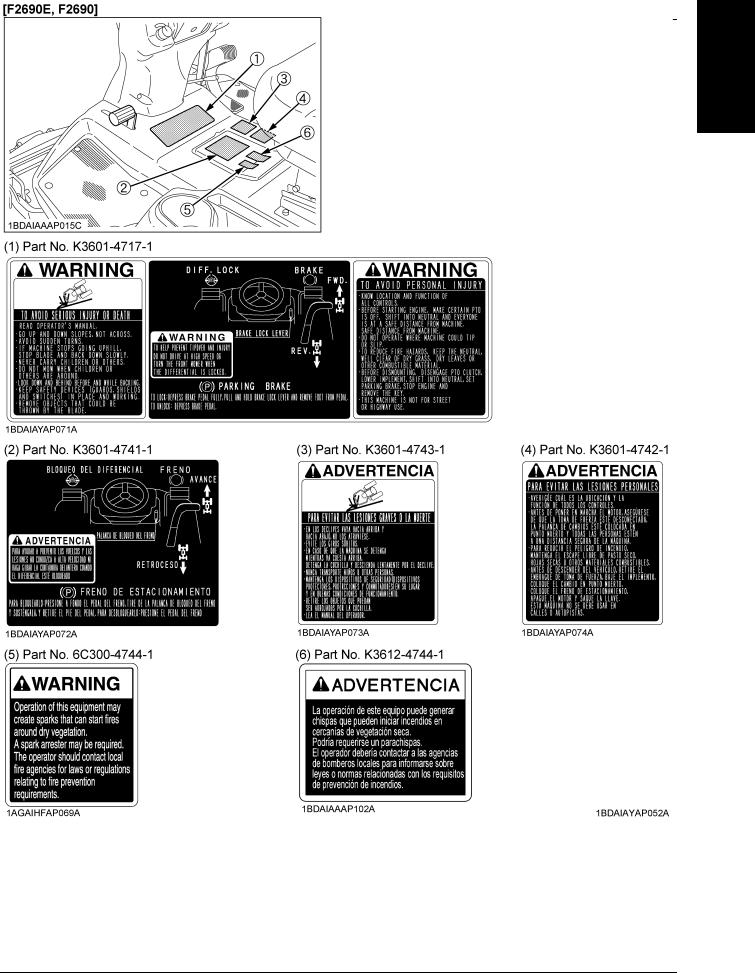
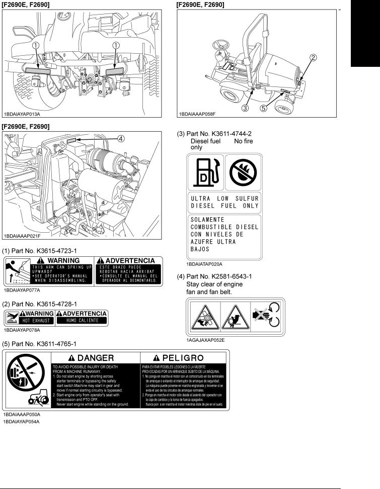
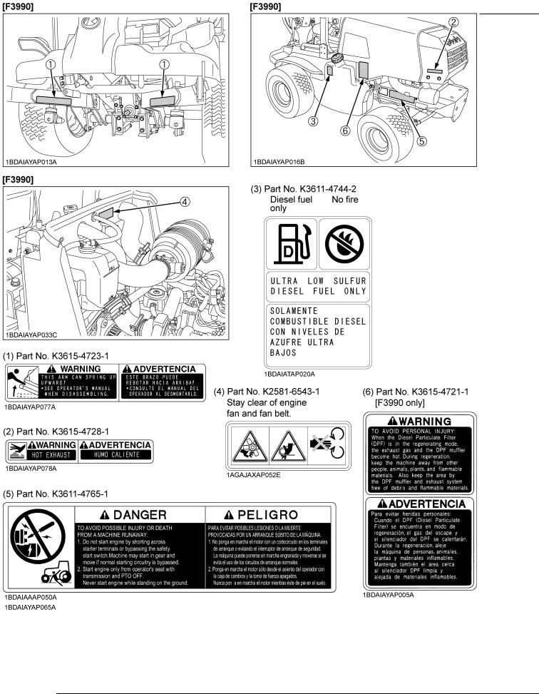
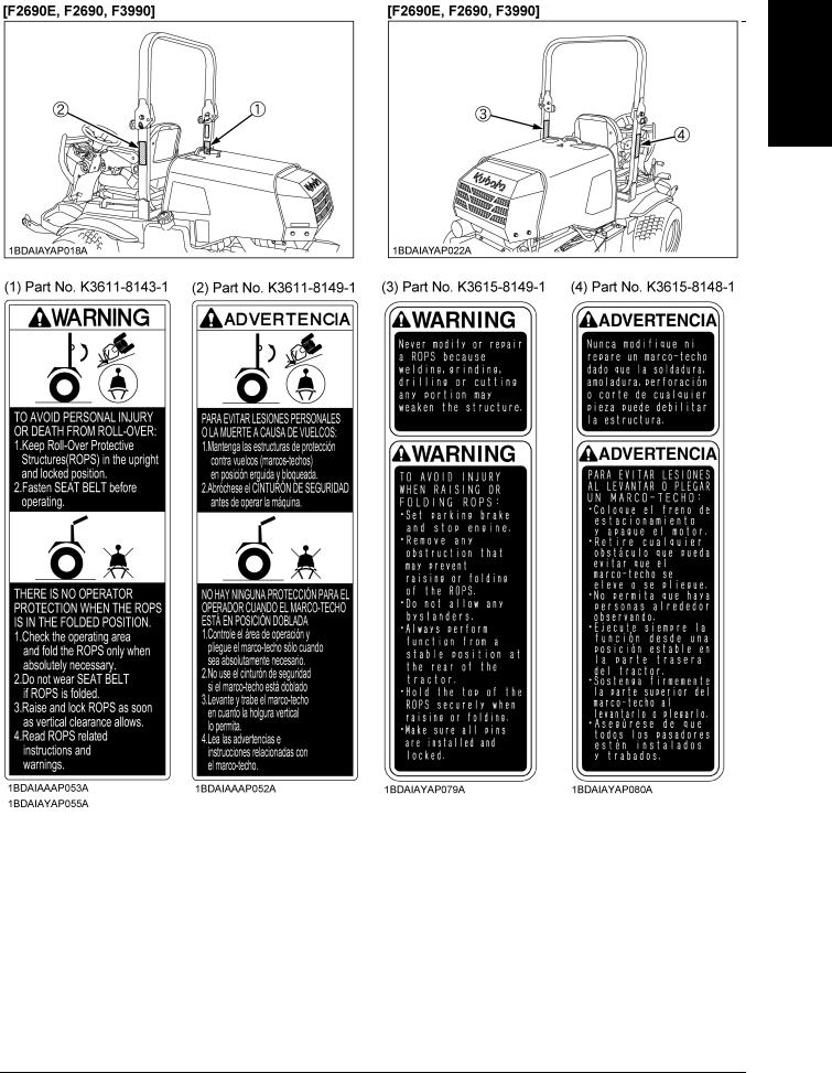
8. DANGER, WARNING AND CAUTION LABELS
SAFE OPERATION  -7
-7
ENGLISH

 -8 SAFE OPERATION
ENGLISH
SAFE OPERATION  -9
-9
ENGLISH
 -10 SAFE OPERATION
ENGLISH
SAFE OPERATION  -11
-11
ENGLISH
 -12 SAFE OPERATION
ENGLISH

|
SAFE OPERATION -13 |
|
|
|
|
ENGLISH |
|
|
|
|
|
9. CARE OF DANGER, WARNING AND CAUTION LABELS |
|
||
|
|
||
1. |
Keep danger, warning and caution labels clean and free from obstructing material. |
|
|
2. |
Clean danger, warning and caution labels with soap and water, dry with soft cloth. |
|
|
3. |
Replace damaged or missing danger, warning and caution labels with new labels from your local KUBOTA Dealer. |
|
|
4. |
If a component with danger, warning and caution label(s) affixed is replaced with new parts, make sure new label(s) is |
|
|
|
(are) attached in the same location(s) as the replaced component. |
|
|
5. |
Mount new danger, warning and caution labels by applying on a clean dry surface and pressing any bubbles to outside |
|
|
|
edge. |
|
|

SERVICING OF MACHINE
After reading this manual thoroughly, you will find that you |
[F3990] |
||
can do some of the regular maintenance yourself. Your |
|
||
dealer is interested in helping you get the best |
|
||
performance from your new machine and wants to help |
|
||
you get the most value from it. When in need of parts or |
|
||
major service, be sure to see your local KUBOTA Dealer. |
|
||
When in need of parts, be prepared to give your dealer the |
|
||
serial number of the machine, ROPS and engine. |
|
||
Locate the serial numbers now and record them in the |
|
||
space provided. |
|
|
|
|
|
|
|
|
Type |
Serial No. |
|
|
|
|
|
Machine |
|
|
|
|
|
|
|
Engine |
|
|
|
|
|
|
|
ROPS |
|
|
|
|
|
|
|
Date of Purchase |
|
|
|
|
|
|
|
Name of Dealer |
|
|
|
|
|
|
|
(To be filled in by purchaser) |
|
|
|
|
|
|
|
[F2690E, F2690] |
|
|
|
SERVICING OF MACHINE 1
ENGLISH
(1) Machine serial No.
(2) Engine serial No.
[F2690E, F2690, F3990]
(1)Machine serial No.
(2)Engine serial No.
(1) ROPS serial No.

ENGLISH
2 SERVICING OF MACHINE
C Warranty
This machine is warranted under the Kubota Limited Express warranty, a copy of which may be obtained from your selling dealer. No warranty shall, however, apply if the machine has not been handled according to the instruction given in the Operator's Manual even it is within the warranty period.
C Scrapping the machine and its procedure
To put the machine out of service, correctly follow the local rules and regulations of the country or territory where you scrap it. If you have questions, consult your local KUBOTA Dealer.

SPECIFICATIONS 3
SPECIFICATIONS
|
Model |
|
F2690E |
|
F2690 |
|
|
F3990 |
|
|
|
|
|
|
|
|
|
|
|
|
Model |
|
|
D1105 |
|
|
V1505T |
||
|
|
|
|
|
|
|
|
||
|
Engine gross power (SAE) *1 |
kW (HP) |
19 (25.5) |
|
|
28.9 (39) |
|||
|
|
|
|
|
|
||||
|
Type |
|
Indirect Injection. Vertical water - cooled, 4cycle diesel |
||||||
|
|
|
|
|
|
|
|
||
|
Number of cylinders |
|
|
3 |
|
|
4 |
||
|
|
|
|
|
|
|
|
||
|
Bore and stroke |
mm (in.) |
|
78 x 78.4 (3.07 x 3.09) |
|
||||
|
|
|
|
|
|
|
|||
|
Total displacement |
cm (cu.in.) |
1123 (68.53) |
|
|
1498 (91.41) |
|||
|
|
|
|
|
|
|
|
|
|
|
Rated revolution |
rpm |
|
3000 |
|
[PTO ON] 2500 |
|||
Engine |
|
|
[PTO OFF] 2700 |
||||||
|
|
|
|
|
|
|
|||
|
|
|
|
|
|
|
|
||
|
Low idling revolution |
rpm |
|
|
1300 to 1400 |
|
|||
|
|
|
|
|
|
|
|
||
|
Fuel |
|
Diesel fuel No.1 (S-15) [below -10 |
(14 )] |
|||||
|
|
Diesel fuel No.2 (S-15) |
|
|
|
||||
|
|
|
|
|
|
|
|||
|
|
|
|
||||||
|
Starter |
|
Electric starter with battery, glow plug, 12 V, 1.4 kW |
||||||
|
|
|
|
||||||
|
Lubrication |
|
Forced lubrication by gear pump |
||||||
|
|
|
|
||||||
|
Cooling |
|
Liquid with pressurized radiator |
||||||
|
|
|
|
||||||
|
Battery |
|
12 V, RC: 133 min, CCA: 582 A |
||||||
|
|
|
|
|
|
|
|
||
|
Fuel tank |
L (U.S.gals.) |
|
61 (16.1) |
|
|
|||
|
|
|
|
|
|
|
|||
|
Engine crankcase (with filter) *3 |
L (U.S.qts.) |
3.5 (3.7) |
|
|
4.7 (5.0) |
|||
|
|
|
|
|
|
|
|||
|
Engine coolant |
L (U.S.qts.) |
4.6 (4.9) |
|
|
3.7 (3.9) |
|||
|
|
|
|
|
|
|
|||
Capacities |
Recovery tank |
L (U.S.qts.) |
0.6 (0.6) |
|
|
1.1 (1.1) |
|||
|
|
|
|
|
|
|
|||
|
Transmission case |
L (U.S.qts.) |
|
14 (14.8) |
|
|
|||
|
|
|
|
|
|
|
|||
|
Rear axle differential case |
L (U.S.qts.) |
|
1.5 (1.6) |
|
|
|||
|
|
|
|
|
|
|
|||
|
Rear axle gear case |
L (U.S.qts.) |
|
0.5 (0.5) |
|
|
|||
|
|
|
|
|
|
|
|||
|
Overall length |
mm (in.) |
2450 (96.5) |
|
|
2510 (98.9) |
|||
|
|
|
|
|
|
|
|
||
|
Overall width |
mm (in.) |
1240 (48.8) |
|
|
1370 (53.9) |
|||
|
|
|
|
|
|
|
|
|
|
|
|
Without |
mm (in.) |
|
1350 (53.1) |
|
|
||
|
|
ROPS |
|
|
|
||||
|
Overall height |
|
|
|
|
|
|
|
|
|
|
|
|
|
|
|
|
|
|
Dimensions |
With |
mm (in.) |
|
1985 (78.2) |
|
|
|||
|
|
|
|
||||||
|
ROPS |
|
|
|
|||||
|
|
|
|
|
|
|
|
|
|
|
Wheelbase |
mm (in.) |
|
1300 (51.2) |
|
|
|||
|
|
|
|
|
|
|
|||
|
Min. ground clearance |
mm (in.) |
|
185 (7.3) |
|
|
|||
|
|
|
|
|
|
|
|
|
|
|
Tread |
Front |
mm (in.) |
975 (38.4) |
|
|
1063 (41.9) |
||
|
|
|
|
|
|
|
|
|
|
|
Rear |
mm (in.) |
875 (34.4) |
|
|
1020 (40.1) |
|||
|
|
|
|
||||||
|
|
|
|
|
|
|
|
|
|
Weight (W/O mower deck) |
kg (lbs.) |
756 (1667) |
|
770 (1698) |
|
855 (1885) |
|||
|
|
|
|
|
|
|
|
|
|
ENGLISH

ENGLISH
4 |
SPECIFICATIONS |
|
|
|
|
|
|
|
||
|
|
|
|
|
|
|
|
|
|
|
|
|
|
|
|
|
|
|
|
|
|
|
|
Model |
|
|
F2690E |
|
F2690 |
|
F3990 |
|
|
|
|
|
|
|
|
|
|
|
|
|
|
|
Front |
|
|
23 x 10.5 - 12 |
|
24 x 12 - 12 |
||
|
|
|
|
|
(4PR) Turf |
|
(4PR) Turf |
|||
|
|
Tires |
|
|
|
|
||||
|
|
|
|
|
|
|
|
|
|
|
|
|
Rear |
|
|
16 x 6.5 - 8 |
|
18 x 9.5 - 8 |
|||
|
|
|
|
|
|
|||||
|
|
|
|
|
(4PR) Turf |
|
(4PR) Turf |
|||
|
|
|
|
|
|
|
||||
|
|
|
|
|
|
|
|
|
|
|
|
|
|
|
Low |
mph |
|
|
0 to 5.6 (0 to 9) |
|
|
|
|
|
|
(km/h) |
|
|
|
|||
|
|
|
Forward |
|
|
|
|
|
|
|
|
|
|
|
|
|
|
|
|
|
|
|
|
|
High |
mph |
|
|
0 to 12.5 (0 to 20) |
|
||
|
|
|
|
|
|
|
||||
|
|
|
|
(km/h) |
|
|
|
|||
|
|
Traveling speeds *2 |
|
|
|
|
|
|
|
|
|
|
|
|
|
|
|
|
|
|
|
|
|
|
Low |
mph |
|
|
0 to 3.0 (0 to 4.8) |
|
||
|
|
|
|
|
|
|
||||
|
|
|
|
(km/h) |
|
|
|
|||
|
Traveling |
|
Reverse |
|
|
|
|
|
|
|
|
|
|
|
|
|
|
|
|
||
|
|
High |
mph |
|
|
0 to 6.9 (0 to 11) |
|
|||
|
|
|
|
|
|
|||||
|
system |
|
|
|
|
|
||||
|
|
|
(km/h) |
|
|
|
||||
|
|
|
|
|
|
|
|
|
|
|
|
|
|
|
|
|
|
|
|
|
|
|
|
Steering |
|
|
|
|
Power, hydrostatic |
|
||
|
|
|
|
|
|
|
||||
|
|
Transmission |
|
|
Main - hydrostatic transmission. High - Low gear shift |
|||||
|
|
|
|
|
(2 forward, 2 reverse) |
|||||
|
|
|
|
|
|
|
||||
|
|
|
|
|
|
|
|
|
||
|
|
Brake |
|
|
|
|
Wet disk type |
|
||
|
|
|
|
|
|
|
|
|||
|
|
Min. turning radius |
|
mm (in.) |
750 (29.5) (Inside of Front Tire) |
|||||
|
|
|
|
|
|
|
|
|
|
|
|
|
Differential |
Front |
|
|
|
|
Bevel gear |
|
|
|
|
|
|
|
|
|
|
|
|
|
|
|
Rear |
|
|
- |
|
Bevel gear |
|||
|
|
|
|
|
|
|||||
|
|
|
|
|
|
|
|
|
|
|
|
|
4WD system |
|
|
- |
|
Dual - Acting Overrunning 4WD |
|||
|
|
|
|
|
|
|
|
|
|
|
|
|
|
|
|
|
1 speed |
|
1 speed |
||
|
|
Revolution |
|
|
|
(2583 rpm at |
||||
|
|
|
|
(2545 rpm at 3000 engine rpm) |
|
|||||
|
|
|
|
|
|
|
2500 engine rpm) |
|||
|
|
|
|
|
|
|
|
|
|
|
|
|
|
|
|
|
|
|
|
|
|
|
|
|
|
|
|
Shaft drive. KUBOTA 10 tooth |
|
Shaft drive. |
||
|
PTO |
|
|
|
|
|
KUBOTA 10 tooth |
|||
|
Drive system |
|
|
involute spline |
|
|||||
|
|
|
|
|
|
(2545 rpm) |
|
involute spline |
||
|
|
|
|
|
|
|
(2583 rpm) |
|||
|
|
|
|
|
|
|
|
|
|
|
|
|
|
|
|
|
|
|
|
|
|
|
|
Clutch type |
|
|
|
|
Wet multi plates |
|
||
|
|
|
|
|
|
|
|
|
||
|
|
PTO brake |
|
|
|
|
Wet single plate |
|
||
|
|
|
|
|
|
|
|
|
|
|
(Specifications and design subject to change without notice)
NOTE:
*1 Manufacture's estimate
*2 F2690E, F2690: At 3000 engine rpm
F3990: [PTO ON] At 2500 engine rpm, [PTO OFF] At 2700 engine rpm *3 Oil amount when the oil level is at the center of the oil level gauge
IMPLEMENT LIMITATIONS |
5 |
IMPLEMENT LIMITATIONS
The KUBOTA Machine has been thoroughly tested for proper performance with implements sold or approved by KUBOTA. Use of implements which exceed the maximum loading weight listed below, or which are not recommended for use with the KUBOTA Machine may result in malfunctions or failures of the machine, damage to other property and injury to the operator or others. (Any malfunctions or failures of the machine resulting from use with improper implements are not covered by the warranty.)
|
Maximum loading weight |
Lift link end maximum |
|
|
|
|
|
loading weight |
Maximum total weight |
|
Front axle Wf |
Rear axle Wr |
||
|
Wo |
|
||
|
|
|
|
|
F2690E |
|
|
|
|
F2690 |
900 kg (1984 lbs.) |
600 kg (1323 lbs.) |
260 kg (573 lbs.) |
1500 kg (3307 lbs.) |
F3990 |
|
|
|
|
|
|
|
|
|
[F3990]
B IMPORTANT
When you use outlet electric power with a cabin on, do not use with the engine revolution lower than 2000 rpm. Maximum allowance value  25(A) at engine revolution more than 2000 rpm.
ENGLISH
ENGLISH
6 INSTRUMENT PANEL AND CONTROLS
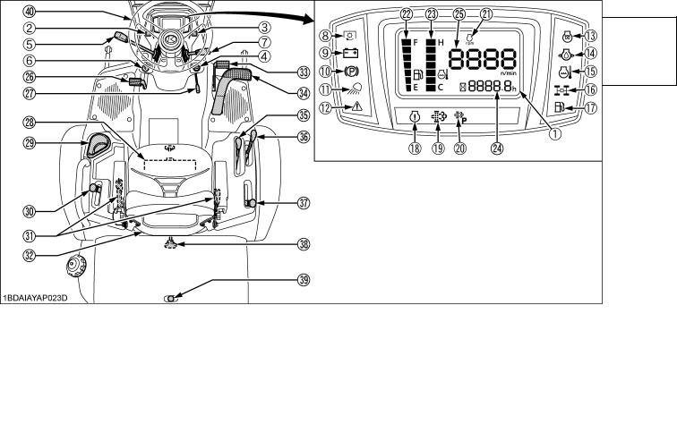
INSTRUMENT PANEL AND CONTROLS
|
ILLUSTRATED CONTENTS |
|
ILLUSTRATED CONTENTS |
||
INSTRUMENT PANEL, SWITCHES and |
|
CONTROLS |
|
||
HAND CONTROLS |
|
|
|
|
|
(1) Liquid crystal display................................................... |
33 |
(26) |
Differential lock pedal........................................... |
31 |
|
(2) Parked regeneration switch [F3990 only].................... |
10 |
(27) |
Parking brake lever.............................................. |
18 |
|
(3) DPF INHIBIT switch [F3990 only]................................ |
10 |
(28) |
Globe box............................................................. |
26 |
|
(4) Key switch.................................................................. |
20 |
(29) |
Cup holder |
|
|
(5) Throttle lever............................................................... |
30 |
(30) |
4WD lock lever (4WD only).................................. |
29 |
|
(6) Head light switch......................................................... |
27 |
(31) |
Seat belt............................................................... |
27 |
|
(7) Steering wheel tilt lever............................................... |
27 |
(32) Operator's seat..................................................... |
26 |
||
(8) PTO clutch indicator................................................... |
18 |
(33) |
Brake pedal.......................................................... |
30 |
|
(9) Electrical charge warning indicator............................. |
32 |
(34) |
Speed control pedal (HST pedal)......................... |
31 |
|
(10) Parking brake warning indicator................................ |
18 |
(35) High - Low gear shift lever..................................... |
29 |
||
(11) |
Head light indicator................................................... |
27 |
(36) |
Hydraulic lift lever................................................. |
28 |
(12) Master system warning indicator............................... |
32 |
(37) |
PTO lever............................................................. |
30 |
|
(13) |
Glow plug indicator................................................... |
18 |
(38) |
Lift link lowering speed control knob.................... |
28 |
(14) |
Engine oil pressure warning indicator....................... |
32 |
(39) |
Hood lock lever.................................................... |
45 |
(15) Engine overheat warning indicator............................ |
32 |
(40) |
Steering wheel |
|
|
(16) |
4WD indicator........................................................... |
29 |
|
|
|
(17) Fuel level indicator.................................................... |
18 |
|
|
|
|
(18) Engine warning indicator [F3990 only]...................... |
10 |
|
|
|
|
(19) Regeneration indicator [F3990 only]......................... |
10 |
|
|
|
|
(20) |
Parked regeneration indicator [F3990 only].............. |
10 |
|
|
|
(21) Constant RPM management indicator [F3990 only].. 35 |
|
|
|
||
(22) Fuel gauge................................................................ |
33 |
|
|
|
|
(23) |
Coolant temperature gauge...................................... |
34 |
|
|
|
(24) |
Hourmeter................................................................ |
34 |
|
|
|
(25) |
Tachometer.............................................................. |
34 |
|
|
|
|
|
|
|
|
|
MOWER MOUNTING 7
MOWER MOUNTING
MOUNTING THE MOWER
To avoid serious injury:
A Before mounting the mower deck, read and understand the use of the lift link lowering speed control knob.
(See "Lift Link Lowering Speed Control Knob" in "OPERATING THE MACHINE" section in the operator's manual of the machine.)
A Place the PTO lever in the "DISENGAGE" position.
A Place the High-Low gear shift lever in the
"NEUTRAL" position.
A The mower links (left hand, right hand) are spring-loaded. Have an assistant hold the arm in position when mounting the mower deck.
1.Move the mower deck under the mower links and place the hydraulic lift lever in the "DOWN" position.
2.Attach the front end of the mower links to the mower deck with clevis pins and set pins.
(1)Mower link
(2)Set pin
(3)Clevis pin
3.Start the engine, raise the mower deck, lock the lift link lowering speed control knob and shut off the engine.
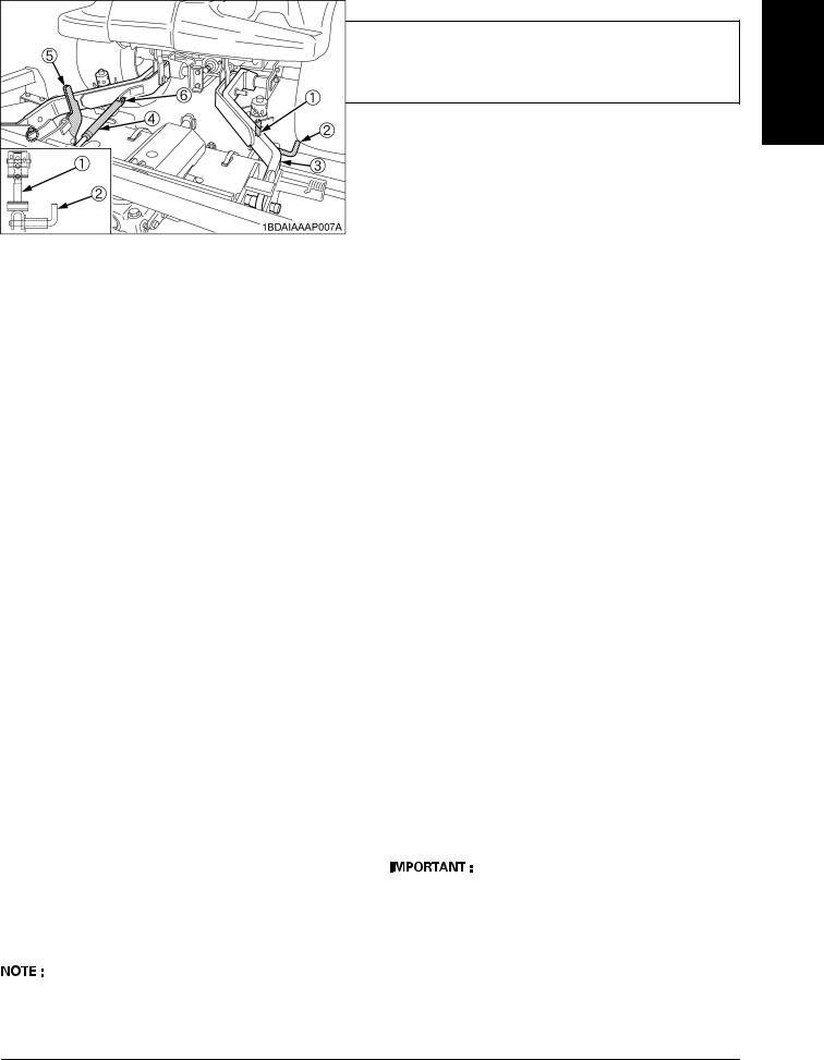
4.Install the lift rods to the mower deck with lock pins and lower the mower deck on the ground.
[RCK72P-F39 / RCK72R-F36]
5.Attach the gas spring to the mower link with the clevis pin and the rue ring cotter.
AWhen operating the mower, make sure the tilt lever is unlocked.
A For tilting up the mower, see "MOWER TILT UP" section in the operator's manual of the mower.
(1) |
Lift rod |
(4) |
Gas spring |
(2) |
Lock pin |
(5) |
Tilt lever ("UNLOCKED" position) |
(3) |
Mower link |
(6) |
Rue ring cotter |
6.Pull back the coupler of the universal joint.
Push the universal joint onto the PTO shaft until the coupler locks.
Slide the universal joint backward and forward to check that the universal joint is locked securely.
(1)Coupler
(2)Universal joint
AFinally pull the universal joint to see if it is locked tight in position.
After mounting the mower deck, adjust the lift link lowering speed.
(See "CONTROLS" in "INSTRUMENT PANEL AND CONTROLS" section.)
ENGLISH
 Loading...