

Page 1
OPERATOR'S MANUAL
U.S.A. :KUBOTATRACTORCORPORATION
Canada :KUBOTACANADALTD.
France :KUBOTAEUROPES.A.S
Italy :KUBOTAEUROPES.A.SItalyBranch
Germany :KUBOTABAUMASCHINENGmbH
U.K. :KUBOTA(U.K.)LTD.
Australia :KUBOTATRACTORAUSTRALIAPTYLTD.
Malaysia :SIMEKUBOTASDN.BHD.
Philippines :KUBOTAPHILIPPINES,INC.
Taiwan :SHINTAIWANAGRICULTURALMACHINERYCO.,LTD.
Thailand :SIAMKUBOTACORPORATIONCO.,LTD.
1000
KubotaDrive,Grapevine,TX
Telephone:
590014
Telephone:(
19-25
Telephone:(
ViaGrandi,
Telephone:(
Steinhauserstr,
Telephone:(
DormerRoad,Thame,Oxfordshire,OX
Telephone:(
25-29
Telephone:(
3
No.
Seksyen
Telephone:(
232
QuirinoHi㷅hway,Baesa,QuezonCity
Telephone:(
16
,Fen㷅pin㷅2ndRd,TaliaoShian㷅Kaohsiun㷅
Telephone:(
101/19-24
Pathumthani
Telephone:(
888-4
KUBOTA
thAvenue,Markham,Ontario,L3S4K4,Canada
905)294-7477
,RueJulesVercruysse,Z.I.BP88,
33)1-3426-3434
2920068
PermasWay,Tru㷅anina,VIC
JalanSepadu25/
25,40400
Moo20,NavanakornIndustrialEstate,TambonKhlon㷅nuen㷅,AmphurKhlon㷅luan㷅,
PeschieraBorrome(MI)Italy
39)02-51650377
100,66482
49)6332-4870100
44)1844-214500
61)-3-9394-4400
123
ShahAlam,Selan㷅orDarulEhsanMalaysia
60)3-736-1388
63)2-422-3500
886)7-702-2333
12120
,THAILAND
66)2-909-0300
76051
95101
ZweibruckenRheinlandpfalzGermany
93
3029
,Australia
TamanPerindustrianAxis,
Ar㷅enteuilCedex,France
UN,U.K.
1106
,Philippines
83107
,TaiwanR.O.C.
KUBOTA
EXCAVATOR
MODEL
U
27-4
AV. I. 1-1. -. K
Japan :KUBOTACorporation
Farm&IndustrialMachineryInternationalOperationsHeadquarters
2-47
,Shikitsuhi㷅ashi1-chome,Naniwa-ku,Osaka,Japan
556-8601
English (U.S.A.)
Code No. RH418-8193-1
KUBOTA Corporation 2017
©
U
2
7
4
1BAAEAPAP0010 1BAAEABAP0280
READ AND SAVE THIS MANUAL
Page 2

ABBREVIATION LIST
Abbreviations Definitions
AI
API
ASTM
CECE
DIN
EN
FRONT
Hi
ISO
JIS
L
L/min
Lo
MIL
OPG
OSHA
Auto Idle
American Petroleum Institute
American Society for Testing and Materials, USA
Committee for European Construction Equipment
Deutsches Institut für Normung, GERMANY
(German Institute for Standardization)
European Standard
"Front" means the direction towards the boom and dozer
High speed
International Organization for Standardization
Japanese Industry Standard
Volume (Liter)
Liter per minute
Low speed
Military Standard
Operator Protective Guards
Occupational Safety and Health Administration
ROPS
rpm
SAE
TPSS
Roll-Over Protective Structure
Revolutions Per Minute
Society of Automotive Engineers, USA
Two Pattern Selection System
California Proposition 65
WARNING
Engine exhaust, some of its constituents,
certain vehicle components and fluids,
contain or emit chemicals known to the
State of California to cause cancer and birth
defects or other reproductive harm.
IMPORTANT
The engine in this machine is not equipped by the manufacturer
with a standard spark arrester.
It is a violation of California Public Resource Code Section 4442 to
Use or operate this engine on or near any forest-covered, brushcovered land, or grass-covered land unless the exhaust system is
equipped with a working spark arrester meeting state laws. Other
states or federal areas may have similar laws.
U27-4
English (U.S.A.)
Page 3
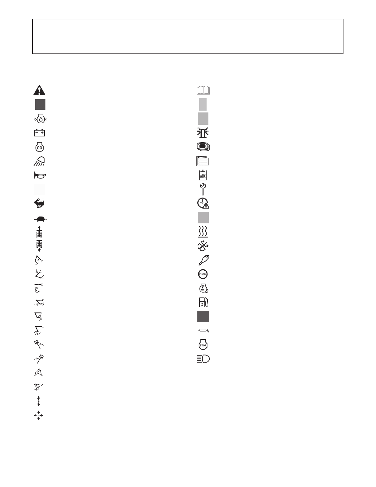
GENERAL SYMBOLS
The instruments and operation elements have been marked with a series of symbols in order to simplify the operation of
your excavator. These symbols are listed below with the respective descriptions.
Warning light
Fuel indicator
Engine oil indicator
Charge indicator
Glow indicator
Working lights
Horn
Hydraulic oil
Travel speed
Low speed
Forward travel
Backward travel
Raise boom
Read operator’s manual
Bolted
Released
Rotary beacon
Display selector switch
Menu button
Auxiliary port indicator
Service interval indicator
Set clock indicator
Indicator coolant temperature
Fan
Indirect return flow
Direct return flow
Lower boom
Arm crowd
Arm dump
Bucket crowd
Bucket dump
Swivel boom (left)
Swivel boom (right)
Dozer up
Dozer down
Lever direction
Control lever direction
System lamp
Warning lamp “Auto Idle (AI) Lamp”
Diesel
Gear oil
Grease
Engine stop control lamp
Working light switch
Page 4
FOREWORD
You are now the proud owner of a KUBOTA Excavator. This excavator is a product
of KUBOTA quality engineering and manufacturing. It is made of fine materials and
under a rigid quality control system. It will give you long, satisfactory service. To
obtain the best use of your excavator, please read this manual carefully. It will help
you become familiar with the operation of the excavator and contains many helpful
hints about excavator maintenance. It is KUBOTA's policy to utilize as quickly as
possible every advance in our research. The immediate use of new techniques in
the manufacture of products may cause some small parts of this manual to be
outdated. KUBOTA distributors and dealers will have the most up-to-date
information. Please do not hesitate to consult with them.
SAFETY FIRST
This symbol, the industry's "Safety Alert Symbol", is used throughout this manual
and on labels on the machine itself to warn of the possibility of personal injury.
Read these instructions carefully. It is essential that you read the instructions and
safety regulations before you attempt to assemble or use this unit.
DANGER :
WARNING :
CAUTION :
IMPORTANT :
NOTE : Gives helpful information.
Indicates an imminently hazardous situation which, if not
avoided, will result in death or serious injury.
Indicates a potentially hazardous situation which, if not
avoided, could result in death or serious injury.
Indicates a potentially hazardous situation which, if not
avoided, could result in minor or moderate injury.
Indicates that equipment or property damage could result if
instructions are not followed.
Page 5

CONTENTS
SAFE OPERATION ............................................................................................ -1
DEALER SERVICE...................................................................................................... 1
TECHNICAL DATA...................................................................................................... 3
DESCRIPTION OF MACHINE PARTS........................................................................ 4
INSTRUMENT PANEL AND CONTROL ELEMENTS................................................. 5
CHECKS BEFORE START ......................................................................................... 8
DAILY CHECKS....................................................................................................... 8
CAB TYPE MACHINES ........................................................................................... 8
Wiper/Washer Switch .......................................................................................................8
Interior Lamp..................................................................................................................... 8
Working Light Switch ........................................................................................................9
Heater Switch ...................................................................................................................9
Opening/Closing of CAB Door........................................................................................ 10
Opening/Closing of Front CAB Window..........................................................................10
Opening/Closing of Side CAB Window........................................................................... 11
Emergency Hammer....................................................................................................... 11
HANDLING THE SAFETY DEVICES..................................................................... 11
Pilot Control Lock Lever.................................................................................................. 11
OPERATION OF THE ENGINE................................................................................. 12
STARTING THE ENGINE ...................................................................................... 12
Display Selector Switch .................................................................................................. 13
Battery Charge Lamp...................................................................................................... 15
Engine Oil Pressure Warning Lamp ...............................................................................15
Glow Lamp......................................................................................................................15
LCD for Normal Operation.............................................................................................. 16
LCD for Warning............................................................................................................. 17
Warning Lamp ................................................................................................................17
Checkpoints after Starting the Engine ............................................................................18
STARTING THE ENGINE UNDER COLD CONDITIONS...................................... 18
Precautions in case of Overheat.....................................................................................18
STOPPING THE ENGINE...................................................................................... 19
Engine Stop Button.........................................................................................................19
STARTING WITH AN AUXILIARY BATTERY ....................................................... 19
Observe Following Guidelines when Starting with an Auxiliary Battery..........................19
EXCAVATOR OPERATION ...................................................................................... 21
RUNNING-IN OF THE NEW EXCAVATOR........................................................... 21
Do not Work with Full Engine Rpm's or Full Loads during the First 50 Working Hours.. 21
Oil Change in the Run-in Stage...................................................................................... 21
Seat Belt .........................................................................................................................21
STARTING ............................................................................................................. 21
Operator's Seat...............................................................................................................21
Pilot Control Lock Lever.................................................................................................. 22
Working Light Switch ......................................................................................................22
Page 6

CONTENTS
Travel Buzzer.................................................................................................................. 22
Beacon Light Switch ....................................................................................................... 22
TWO PATTERN SELECTION SYSTEM (TPSS) ................................................... 23
Pattern Change............................................................................................................... 23
OPERATION OF THE BOOM................................................................................ 24
OPERATION OF THE ARM................................................................................... 24
OPERATION OF THE BUCKET ............................................................................ 25
SWIVEL(UNIT SWING)OPERATION .................................................................... 25
BOOM SWING OPERATION................................................................................. 25
OPERATION OF THE DOZER .............................................................................. 26
AUX PORT OPERATION....................................................................................... 26
One-way Hold Switch .....................................................................................................27
DRIVING ................................................................................................................ 28
Drive Levers (Right, Left)................................................................................................29
Throttle Lever..................................................................................................................29
Travel Speed Switch.......................................................................................................30
TURNS................................................................................................................... 30
Pivot Turn ....................................................................................................................... 30
Spin Turn ........................................................................................................................31
UP AND DOWNHILL TRAVELLING ...................................................................... 32
PARKING ON A SLOPE ........................................................................................ 32
PARKING ............................................................................................................... 32
1-way or 2-way CIRCUIT SELECTION VALVE OPERATION ............................... 33
IMPORTANT INFORMATION ON EXCAVATOR OPERATION ............................ 34
HOW TO RELEASE PRESSURE TRAPPED IN THE HYDRAULIC SYSTEM...... 34
TRANSPORTING THE EXCAVATOR ON A TRUCK................................................ 35
LIFTING OF THE EXCAVATOR................................................................................ 37
MAINTENANCE......................................................................................................... 39
MAINTENANCE INTERVALS ................................................................................ 39
OPENING AND CLOSING OF PARTS.................................................................. 41
Opening and Closing of the Fuel Tank Cap....................................................................41
Opening/Closing of the Engine Hood .............................................................................41
Opening/Closing of the Side Cover ................................................................................42
Opening/Closing of the Radiator Cover..........................................................................42
Opening/Closing of the Swivel Frame Cover.................................................................. 42
Where to store the Grease Gun......................................................................................42
Where to keep Operator's Manual..................................................................................43
Cup Holder......................................................................................................................43
DAILY CHECKS..................................................................................................... 43
Checking Coolant Level..................................................................................................43
Checking Fuel Level .......................................................................................................44
Checking Engine Oil Level.............................................................................................. 44
Checking Hydraulic Oil Level.......................................................................................... 45
Lubrication Points ........................................................................................................... 46
Check Fan Belt ...............................................................................................................47
Checking Radiator and Oil Cooler ..................................................................................47
Checking Washer Liquid (only for CAB type) .................................................................48
Checking and Cleaning Engine and Electrical Wiring.....................................................48
Washing Whole Machine................................................................................................ 48
Page 7

CONTENTS
REGULAR CHECKS AND MAINTENANCE WORK ................................................. 49
EVERY 50 SERVICE HOURS ............................................................................... 49
Draining the Water from the Fuel Tank...........................................................................49
Draining Water Separator............................................................................................... 49
Battery ............................................................................................................................ 50
Battery Charging.............................................................................................................50
Greasing of Swing Bearing Teeth...................................................................................51
EVERY 200 SERVICE HOURS ............................................................................. 51
Checking Fan Belt Tension.............................................................................................51
Checking Radiator Hoses and Clamps...........................................................................52
Inspection and Cleaning Air Filter Element.....................................................................52
Air Filter Maintenance..................................................................................................... 53
Greasing Swing Bearing................................................................................................. 53
Checking Fuel Line and Intake Air Line ..........................................................................53
EVERY 250 SERVICE HOURS ............................................................................. 54
Lubrication of the Pilot Valve .......................................................................................... 54
EVERY 500 SERVICE HOURS ............................................................................. 54
Changing Engine Oil (Change the engine oil every 500 hours, or every 1 year in the case
that service hour is less than 500 hours)........................................................................54
Replacing Engine Oil Filter Cartridge (Replace the engine oil filter cartridge every 500
hours,or every 1 year in the case that service hour is less than 500 hours)...................55
Drive unit Oil Change(First Oil Change of the 50 hours) ................................................ 56
Replacing Fuel Filter Cartridge....................................................................................... 56
Replacing Hydraulic Return Filter Element..................................................................... 57
EVERY 1000 SERVICE HOURS ........................................................................... 57
Replacing the Hydraulic Pilot Filter Element...................................................................57
Hydraulic Oil Change (Including Replacing of the Suction Filter in the Hydraulic Tank) 58
Hydraulic Oil Check with Hydraulic Breakers .................................................................59
EVERY 1000 SERVICE HOURS OR ONCE A YEAR ........................................... 59
Replacing Air Filter Element ...........................................................................................59
EVERY 1500 SERVICE HOURS ........................................................................... 59
Checking Fuel Injection Nozzle (Injection Pressure) ...................................................... 59
EVERY 2000 SERVICE HOURS ........................................................................... 59
Changing Front Idler and Track Roller Oil ......................................................................59
Checking the Alternator and Starter Motor .....................................................................59
EVERY 3000 SERVICE HOURS ........................................................................... 60
Checking Injection Pump................................................................................................60
ANNUAL SERVICING............................................................................................ 60
Electrical Wiring and Fuses ............................................................................................60
Checking the Electrical Circuit ........................................................................................60
BIENNIAL SERVICING .......................................................................................... 60
Replacement of Radiator Hoses and Hose Clamps ....................................................... 60
Changing Radiator Coolant ............................................................................................60
Replacing Fuel Hoses and Hose Clamps.......................................................................61
Replacing Intake Air line.................................................................................................61
OTHER ADJUSTMENTS AND REPLACEMENTS.................................................... 62
PURGING OF THE FUEL SYSTEM ...................................................................... 62
ADJUSTMENT OF TRACKS ................................................................................. 62
Special Information when Using Rubber Tracks.............................................................63
CHANGING THE BUCKET .................................................................................... 64
FUSES ................................................................................................................... 64
Page 8

CONTENTS
Replacing Fuses............................................................................................................. 64
Fuse Capacities and Circuits.......................................................................................... 64
Slow Blow Fuse ..............................................................................................................64
TROUBLESHOOTING............................................................................................... 65
KUBOTA I.C.S. NAVIGATION LIST OF MESSAGES ........................................... 66
OPERATION UNDER COLD WEATHER CONDITIONS .......................................... 71
PREPARATION FOR OPERATION IN COLD WEATHER .................................... 71
PROCEDURE AFTER COMPLETING WORK ...................................................... 71
LONG STORAGE ...................................................................................................... 72
RECOMMENDED OILS............................................................................................. 74
MAIN DIMENSIONS .................................................................................................. 76
LIFTING CAPACITY .................................................................................................. 78
Page 9
SAFE OPERATION
-1SAFE OPERATION
Careful operation is your best insurance against an
accident.
Read and understand this manual carefully, before
operating the excavator.
Every user, however experienced, should carefully read
and understand this manual and those of the attachments
and accessories before operating the excavator. The
owner is obliged to inform all operators of these
instructions in detail.
Keep this manual in the storage location. (See "Where to
keep Operator's Manual" in "MAINTENANCE" section.)
1. BEFORE OPERATION
1. Know your equipment and its limitations. Read and
understand this entire manual before attempting to
start and operate the excavator.
2. Pay special attention to and obey the danger, warning
and caution labels on the machine.
3. For your safety, a ROPS/OPG (Top Guard Level I)
with a seat belt is installed by KUBOTA.
A ROPS: Roll-Over Protective Structure
A OPG (Top Guard Level I): Operator Protective
Guards of Top Guard Level I
OPG (Top Guard Level I) in accordance with
ISO10262 is equivalent in definition to FOPS (Falling
Object Protective Structure).
Always use the seat belt when the machine is
equipped with a ROPS/OPG (Top Guard Level I) as
this combination will reduce the risk of serious injury or
death, should the excavator be upset or falling objects
occur.
Do not modify any structural members of the ROPS/
OPG (Top Guard Level I) by welding, drilling, bending,
grinding or cutting, as this may weaken the structure.
If any component is damaged, replace it. Do not
attempt repairs. If the ROPS/OPG (Top Guard Level I)
is loosened or removed for any reason, make sure all
parts are reinstalled correctly. Tighten mounting bolts
to proper torque.
4. ROPS meets requirements of ISO 3471.
OPG (Top Guard Level I) meets requirements of
OSHA 1926 1003/ISO 10262.
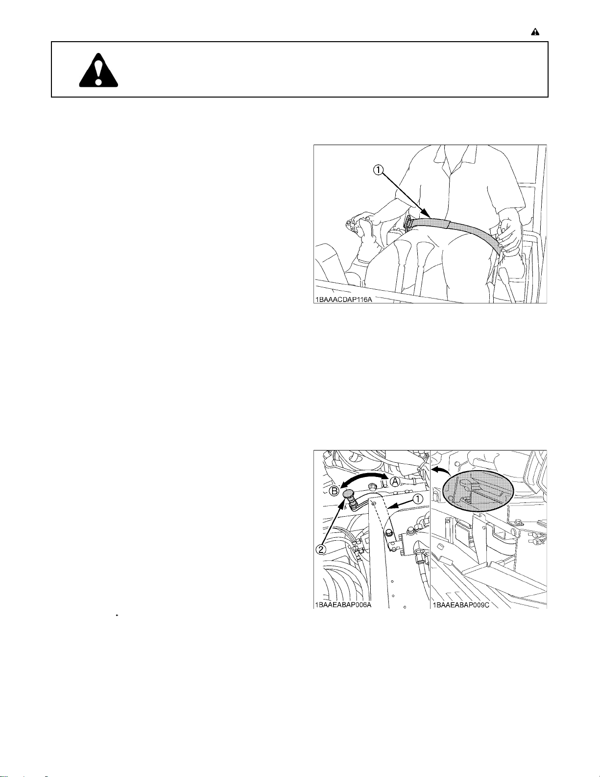
5. The seat belt must be inspected regularly and
replaced if frayed or damaged.
(1) Seat belt
6. Always sit in the operator's seat when starting engine
or operating levers or controls.
7. Study control lever pattern A and pattern B. Then
choose the one which is most familiar.
Familiarize yourself with the pattern selected by
operating the unit slowly and at low engine speed.
A The lever and red knob will be locked automatically
when the new pattern position is reached.
A Do not operate the excavator unless the lever and red
knob have been locked into a pattern position.
(1) Pattern selector lever
(Two Pattern Selection System: TPSS)
(2) Red knob
(A) "Pattern A"
(B) "Pattern B"
Page 10
SAFE OPERATION-2
8. Do not operate the excavator while under the influence
of alcohol, medication, controlled substances or while
fatigued.
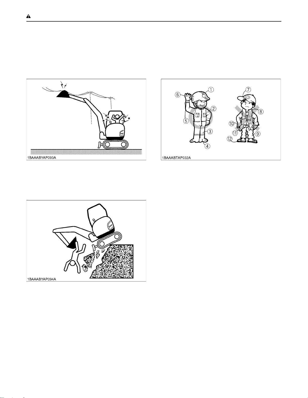
9. Check the surroundings carefully before using the
excavator or when attachments are being attached.
A Pay attention to the overhead clearance with electric
wires.
A Check for pipes and buried cables before digging. Use
your local utility service to check for such items (if
available).
A Check for hidden holes, hindrances, soft underground,
and overhangs.
11.Do not wear baggy, torn or oversized clothing when
working with the excavator as such clothing can get
caught in rotating parts or control elements which can
cause accidents or injuries. Wear adequate safety
clothing, e.g. safety helmet, safety shoes, eye
protection, ear protection, working gloves, etc., as
necessary and as prescribed by law or statutes.
(1) Helmet
(2) Clothing fit for work
(3) Tight seams
(4) Good grip footwear
(5) Well fitting cuffs
(6) Working gloves
(7) Soft hat
(8) Towel
(9) Baggy trousers
(10) Loose cuffs of the shirt
(11) Baggy shirt
(12) Sandals or open-toed shoes
A Do not allow any persons within the working range of
the excavator during operation.
10.Do not allow anyone to use the excavator until they
have been advised of the work to be performed and
they have indicated that they have read and
understood the operator's manual.
12.Do not allow passengers to ride on any part of the
excavator at any time. The operator must remain in the
excavator seat during operation.
13.Check levers, pedals and all mechanical parts for
correct adjustment and wear. Replace worn or
damaged parts immediately. Check nuts and bolts
regularly for correct torque.
14.Keep your excavator clean. Heavy soiling, grease,
dust and grass can cause fires, accidents or injuries.
15.Use only KUBOTA authorized attachments.
16.Before starting the excavator, be absolutely sure that
the excavator has been filled with fuel, lubricated,
greased and undergone all necessary maintenance.
17.Do not modify the excavator, as such could lead to
unforeseen safety problems.
18.Do not operate a hydraulic hammer on anything that is
above the operator's seat level as objects may fall into
the operator station.
19.Make sure attachments, particularly those utilizing
quick attach systems, are securely mounted.
20.Install protective guards on the excavator when
working in areas where objects may fall or be thrown.
Page 11
2. OPERATING THE EXCAVATOR
Operator safety is a priority. Safe operation, specifically
with respect to overturning hazards, entails understanding
the equipment and environmental conditions at the time of
use. Some prohibited uses which can affect overturning
hazards include traveling and turning with implements
and loads carried too high etc. This manual sets forth
some of the obvious risks, but the list is not, and cannot
be, exhaustive. It is the operator's responsibility to be alert
for any equipment or environmental condition that could
compromise safe operation.
C Starting
1. Mount and dismount the machine safely. Always face
the machine. Always use handrails and available
steps and keep yourself well balanced. Do not grab or
hold any of the control levers and switches. Do not
jump on or off the machine, whether stationary or in
motion.
2. Start and control the excavator only from the
operator's seat. The driver should not lean out of his
seat when the engine is running.
3. Before starting the engine, make sure that the lock
levers are in the "LOCKED" position and all control
levers and pedals are in their neutral positions and the
seat belt is fastened correctly.
Before starting the engine, make sure that the control
levers, travel lever, pedals and other control elements
are not stuck and can be moved smoothly.
If stuck, for example, a lever may fail to return, possibly
putting you in danger.
If anything wrong is found, immediately pinpoint the
cause and correct it.
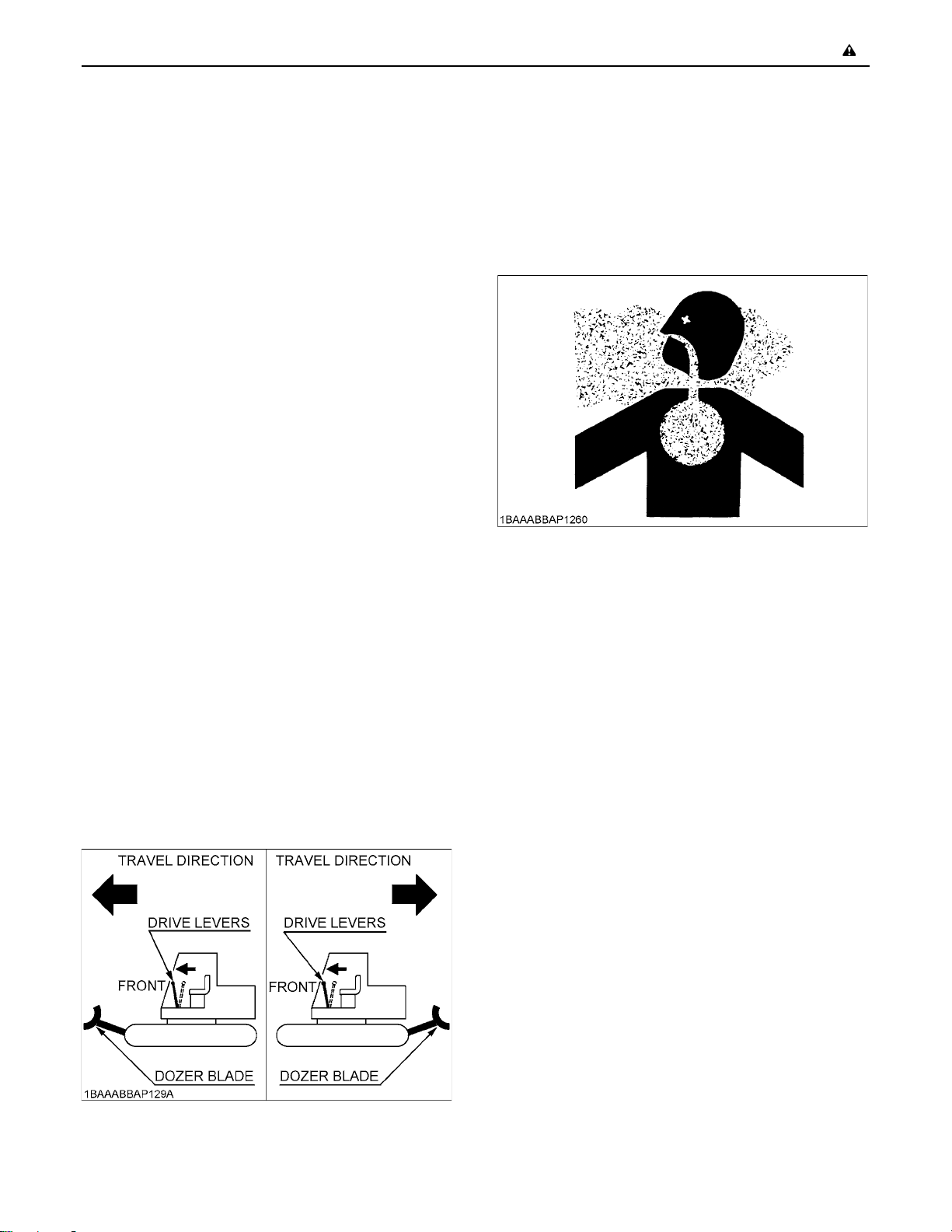
4. Before operating the excavator, make sure that the
dozer blade is in front of you. If the levers are activated
with the dozer blade at the rear, the tracks will move in
the opposite direction of the drive levers.
-3SAFE OPERATION
C Working
1. Do not operate or idle engine in a non-ventilated area.
Carbon monoxide gas is colorless, odorless, and
deadly. If you experience the initial symptoms of low to
moderate co poisoning, which include the following,
stop operation, seek medical attention and contact
your local dealer. These symptoms are: headache,
fatigue, shortness of breath, nausea, or dizziness.
2. Keep all safety equipment and covers in place.
Replace damaged or missing safety devices.
3. When operating, keep hands and body inside of the
ROPS / OPG (Top Guard Level I) protective envelope.
4. Take precautions against tipping over. Stay away from
steep slopes and embankments. Do not swing the
bucket downhill. Lower the dozer blade when digging.
Keep the bucket as low as possible while driving uphill.
Turn slowly on slopes (at reduced speed). Do not
place the excavator near the edges of trenches and
banks, as the earth can give way due to the weight of
the excavator.
Never cross an incline horizontally or at an angle,
which can cause the machine to rollover. Approach
inclines vertically to avoid loss of control.
Avoid performing any work with the machine when it is
on an incline, which could cause it to become
unbalanced and rollover. Always take care when
moving the machine on an incline.
5. Watch where you are going at all times.
Watch for and avoid obstacles. Remain alert for trees,
wires and other obstructions.
6. Do not change direction on steep slopes, or the
excavator could tip over.
Before changing direction, beware of people in the
work area.
7. When the working light alone do not provide sufficient
visibility, prepare additional stationary artificial lighting
and observe safety rules for night work.
8. When towing the excavator or pulling a load, the load
must be less than the strength of the towing line
attached to excavator.
Page 12
SAFE OPERATION-4
Max. drawbar pull at
coupling hook
Max. vertical load at
coupling hook
9. The towing eye should not be used for tie down or
lifting of the machine.
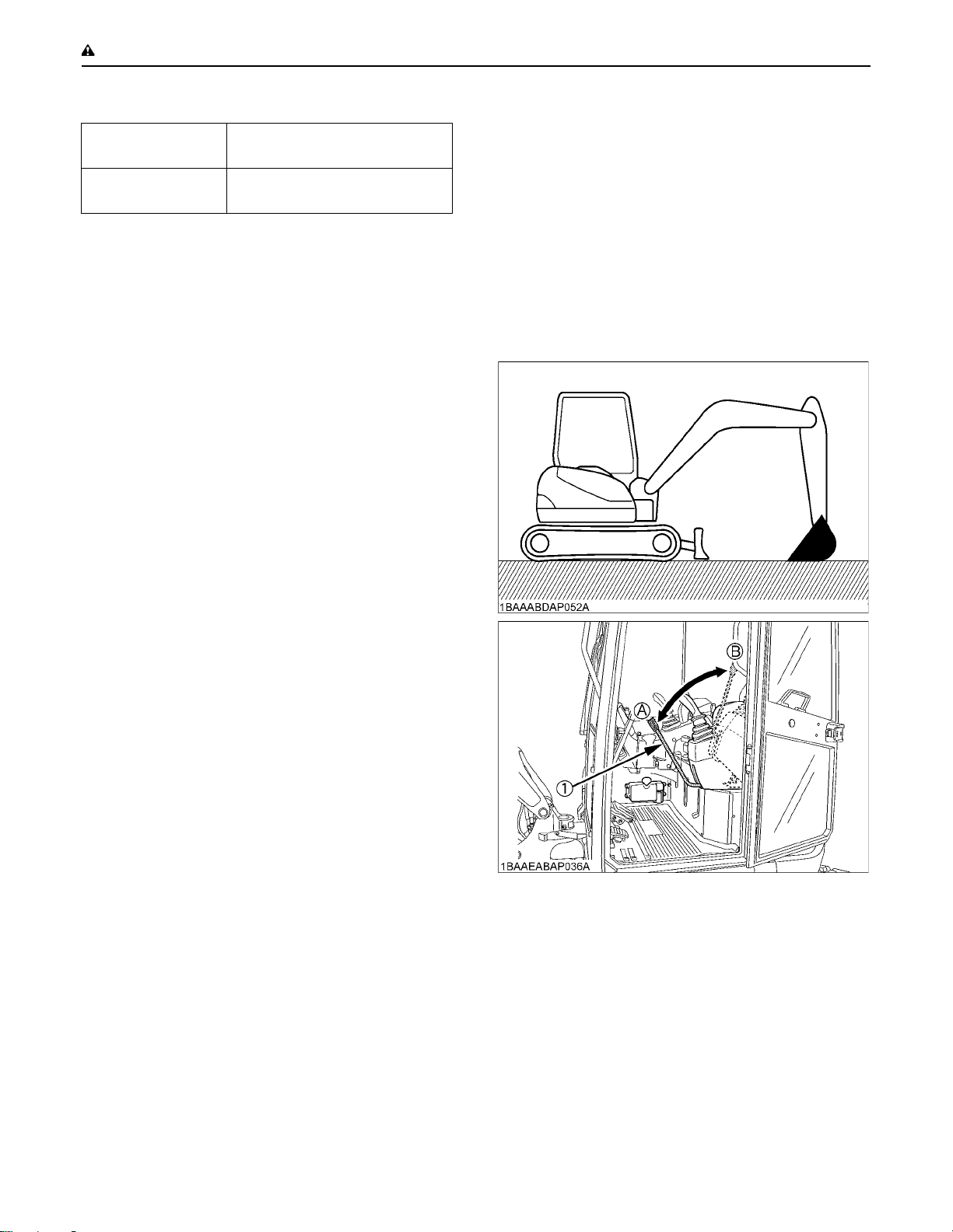
10.When the excavator is parked or left unattended on a
slope, be sure to put the bucket on the ground and
place all control levers in neutral position, then brace
the tracks with chocks.
A When working in groups, always let the others
know what you are going to do before you do it.
Keep others away from the machine working area.
Be sure to lock the boom swing pedal when the
boom swing function is not used.
11.For details of operating the excavator, see the
"EXCAVATOR OPERATION" section.
C Safety for children
Tragedy can occur if the operator is not alert to the
presence of children. Children generally are attracted to
machines and the work they do.
1. Never assume that children will remain where you last
saw them.
2. Keep children out of the work area and under the
watchful eye of another responsible adult.
3. Be alert and shut your machine down if children enter
the work area.
4. Never carry children on your machine. There is not a
safe place for them to ride. They may fall off and be run
over or interfere with your control of the machine.
5. Never allow children to operate the machine even
under adult supervision.
6. Never allow children to play on the machine or on the
attachments.
7. Use extra caution when backing up. Look behind and
down to make sure the area clear before moving.
70.4 kN (7184 kgf) [15838 lbf]
7.2 kN (735 kgf) [1621 lbf]
3. AFTER OPERATION
Before leaving the machine,
A Park the excavator on a firm, flat and level surface. If
this is not possible, park across the slope.
A Lower the attachments and the dozer blade to the
ground.
A Stop the engine.
A Release pressure in the hydraulic system.
A Lock all control levers.
A Remove the key.
A Lock the CAB door (if equipped).
(1) Pilot control lock lever (A) "UNLOCK"
(B) "LOCKED"
Page 13
-5SAFE OPERATION
4. SAFE LOADING AND TRANSPORT OF
THE EXCAVATOR
1. Observe all regulations concerning the transport of
excavators on public roads.
2. Use adequately long and robust ramps when loading
on the machine. (for details see "TRANSPORTING
THE EXCAVATOR ON A VEHICLE")
3. Do not change the running direction and to avoid
tipping over, do not try to swing the attachment
crosswise to the loading ramps.
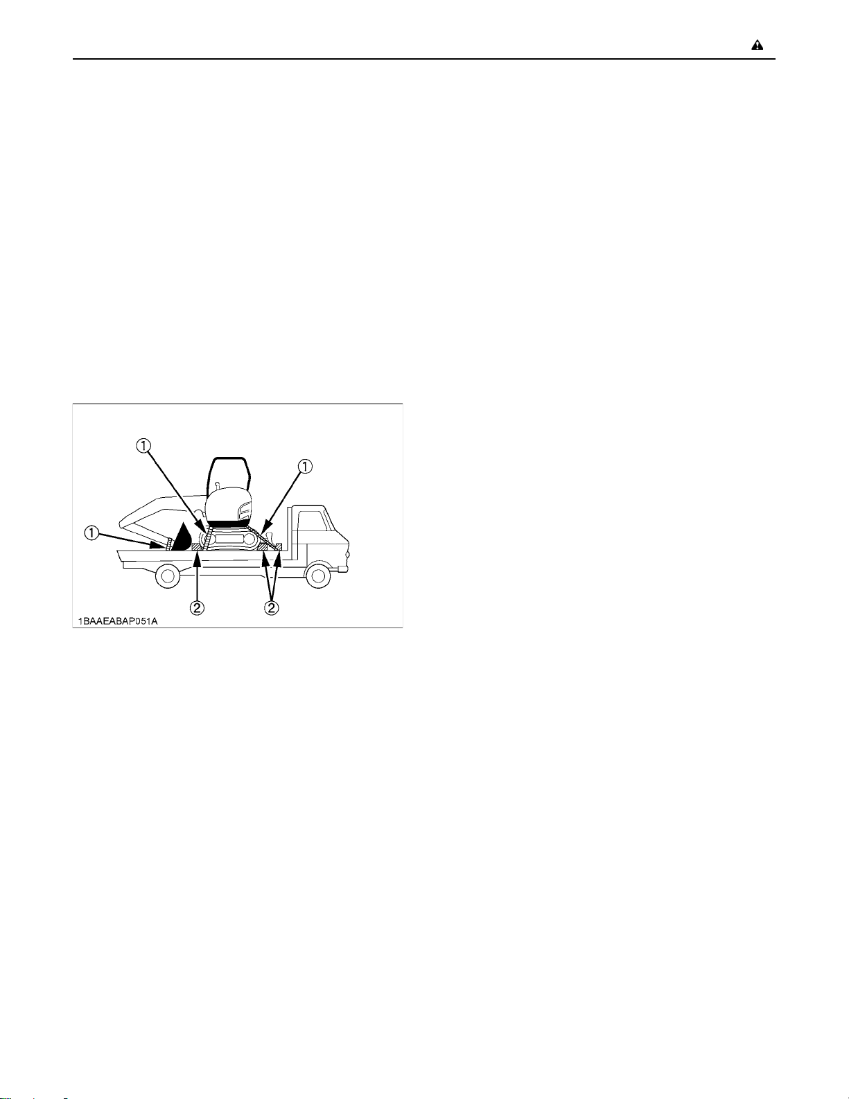
4. Lower the attachment on the loading bed and release
the pressure from the hydraulic system.
Stop the engine then remove the key.
After loading the excavator on the truck, block the
tracks with blocks and tie down the excavator at the
appropriate locations.
(1) Chain
(2) Block
5. MAINTENANCE
Before doing maintenance work on the excavator, place
the machine on a firm, flat and level surface, lower the
attachments to the ground, stop the engine, release
pressure trapped in the hydraulic system, lock all control
levers and remove the key. When dismantling hydraulic
parts, make sure that the hydraulic oil has cooled down
sufficiently to avoid burns.
Start maintenance work carefully, e.g. loosen plug slowly
so that oil will not squirt out.
1. Before doing work on the engine, the exhaust system,
the radiator and the hydraulics, let the excavator cool
down sufficiently.
2. Always turn off the engine when filling the fuel tank.
Avoid spilling and over-filling of fuel.
3. Smoking is prohibited while refueling or handling the
battery. Keep sparks and fire away from the fuel tank
and battery. Flammable gases escape from the
battery, especially during charging.
4. Do not use or charge a refillable type battery if the fluid
level is below the LOWER (lower limit level) mark.
Otherwise, the battery component parts may
prematurely deteriorate, which may shorten the
battery's service life or cause an explosion. Check the
fluid level regularly and add distilled water as required
so that the fluid level is between the UPPER and
LOWER levels.
5. Read and follow the directions "STARTING WITH AN
AUXILIARY BATTERY" in "OPERATION OF THE
ENGINE", when starting with an auxiliary battery.
6. Keep a first-aid box and a fire extinguisher at hand at
all times.
5. Avoid abrupt braking of the vehicle with the excavator
loaded. Sudden braking cause the excavator to move
and may cause a serious accident.
6. Do not use the hooks on the roof of cab or canopy for
lifting the excavator.
Page 14
SAFE OPERATION-6
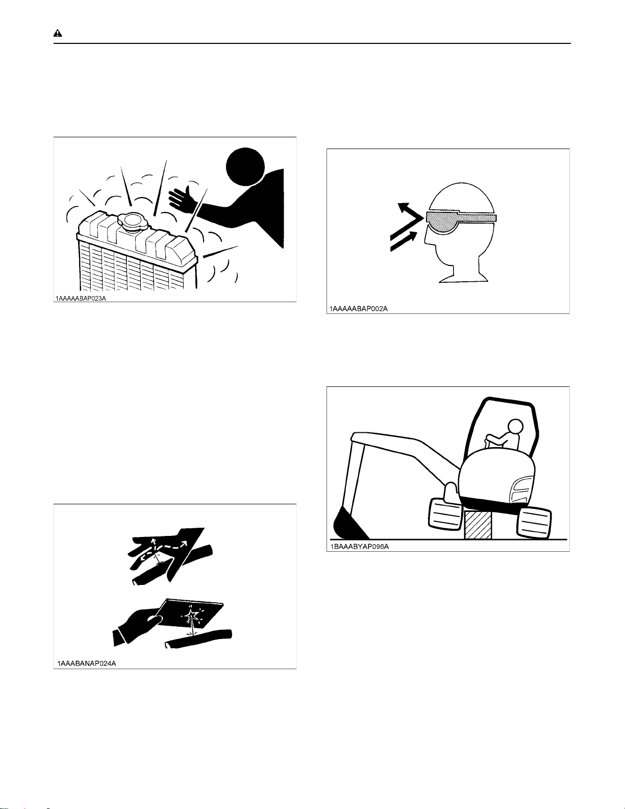
7. Do not open the radiator cap before the radiator has
cooled down sufficiently.
First loosen the cap to the first stop and allow the
system enough time to release the remaining
pressure. Then loosen the cap completely.
8. To avoid short-circuiting the battery, always remove
the ground cable first and attach the positive cable
first.
9. Oil under high pressure can penetrate the skin and
may be harmful to your health if not treated
immediately.
10.Leaking hydraulic fluid has enough pressure to
penetrate the skin and cause serious injuries.
Leakages from pin holes can be totally invisible. Do
not use hands for checking for leaks. Always use a
piece of wood or cardboard. It is strongly
recommended that you use a face mask or eye
protection.
Should injuries occur with leaking hydraulic fluid,
contact a doctor immediately. This fluid can cause
gangrene or serious allergic reactions.
13.To avoid fire, do not heat the hydraulic components
(tanks, pipes, hoses, cylinders) before they have been
drained and washed.
14.Use eye protection or a face mask to protect the eyes
and respiratory system against dust and other foreign
particles.
15.Securely support excavator with stands or suitable
blocking before working underneath. For your safety,
do not work under any hydraulically supported
devices. They can settle, suddenly leak down, or be
accidentally lowered.
11.To avoid environmental damage from acid and heavy
metals, dispose of the battery appropriately.
12.Observe all laws and regulations concerning the
disposal of used oil, coolants, solvents, hydraulic
fluids, battery acids and batteries.
16.Do not dismantle the spring of the track tensioner. If
dismantling is necessary, contact your KUBOTA
dealer where the machine was purchased, or
competent service shop. The assembly must be done
according to the KUBOTA work shop manual (W.S.M.)
for the product involved.
17.When lifting the machine itself with an attachment,
place a safety block or safety post to prevent the
machine from rolling over. Keep the pilot control lock
lever in the "LOCKED" position.
18.Inspect ROPS / OPG (Top Guard Level I) for damage
and if damage is found contact your KUBOTA dealer
for repair.
Page 15

19.KUBOTA does not use asbestos containing
components and recommends against the use of such
components. Components containing asbestos
should be handled in accordance with applicable
regulations and industry practice.
20.Do not open a high-pressure fuel system. Highpressure fluid remaining in fuel lines can cause
serious injury. Do not disconnect nor attempt to repair
fuel lines, sensors, or any other components between
the high- pressure fuel pump and injectors on engines
with high-pressure common rail fuel system.
21.To avoid hazardous high voltage, turn the key switch
to the "STOP" position and disconnect the battery
ground cable if it is necessary to check to repair the
computer, harness or connectors.
22.Fire prevention
Excavator and some attachments have components
that are at high temperatures under normal operating
conditions. The primary source of high temperatures is
the engine and exhaust system. The electrical system,
if damaged or incorrectly maintained, can be a source
of arcing or sparks.
The following fire prevention guidelines will help to
keep your equipment up and running efficiently and
keep the risk of fire to a minimum.
A Blow off all accumulated debris near hot engine
exhaust components such as turbocharger and
exhaust manifold as well as exhaust pipes and muffler
more frequently when working in severe conditions.
A Clean out all accumulated flammable debris such as
leaves, straw, pine needles, branches, bark, small
wood chips and any other combustible materials from
inside the machine belly pans or lower unit structures
as well as from area in proximity to the engine.
A Inspect all fuel lines and hydraulic hoses for wear or for
deterioration. Replace them immediately if they begin
to leak.
A Examine electrical wiring and connectors frequently
for damage. Repair any wires that are loose or frayed
before operating the machine. Clean all electrical
connections and tighten all electrical connections as
necessary.
A Inspect the exhaust system daily for any signs of
leakage. Check for broken pipes and muffler and also
for loose or missing bolts, nuts and clamps. If any
exhaust leaks or fractured parts are found, repairs
must be completed prior to operation.
A Always keep a multipurpose fire extinguisher on or
near the machine. Be familiar with the operation of the
fire extinguisher.
-7SAFE OPERATION
Page 16
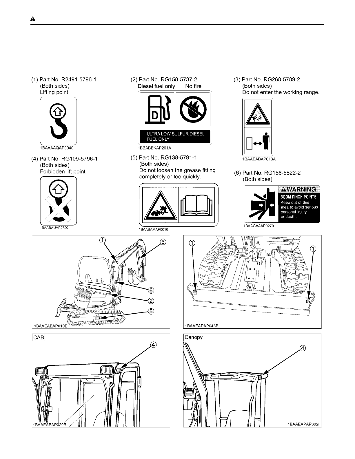
SAFE OPERATION-8
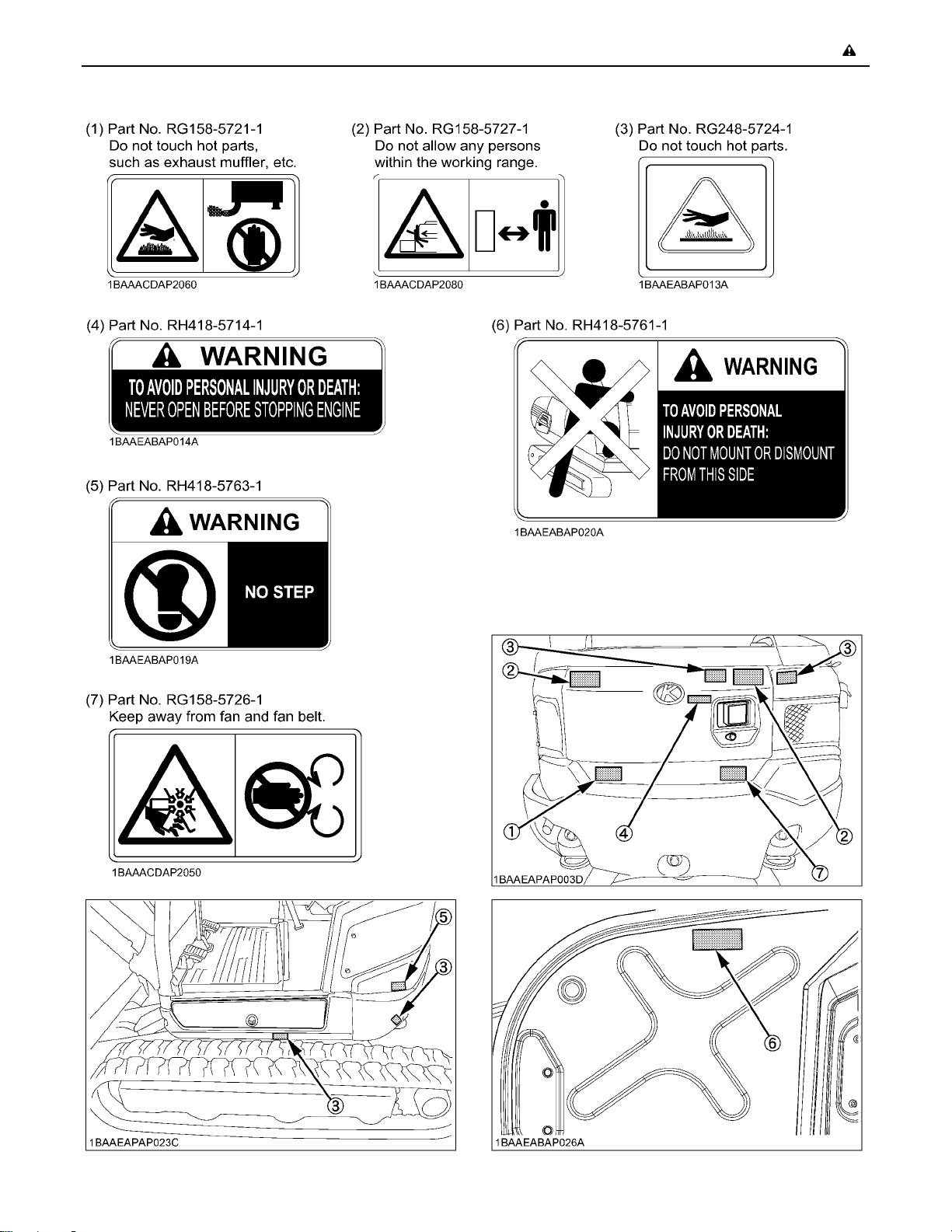
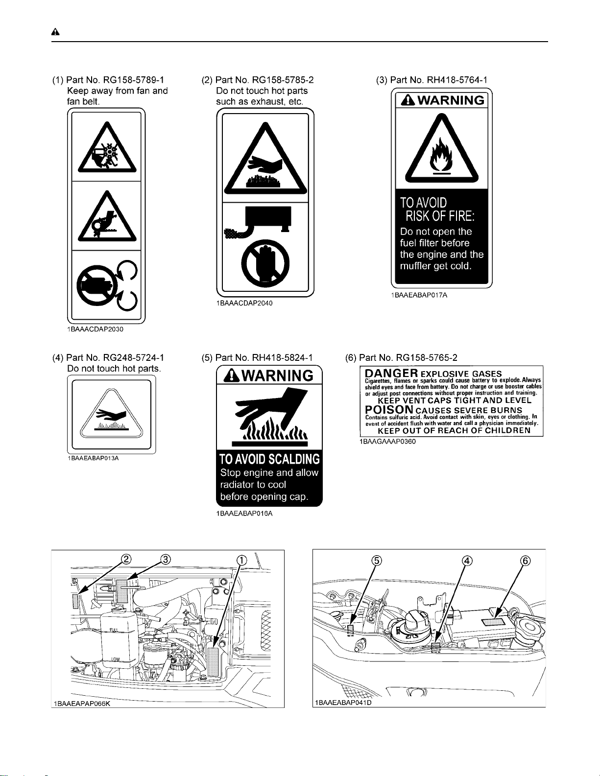
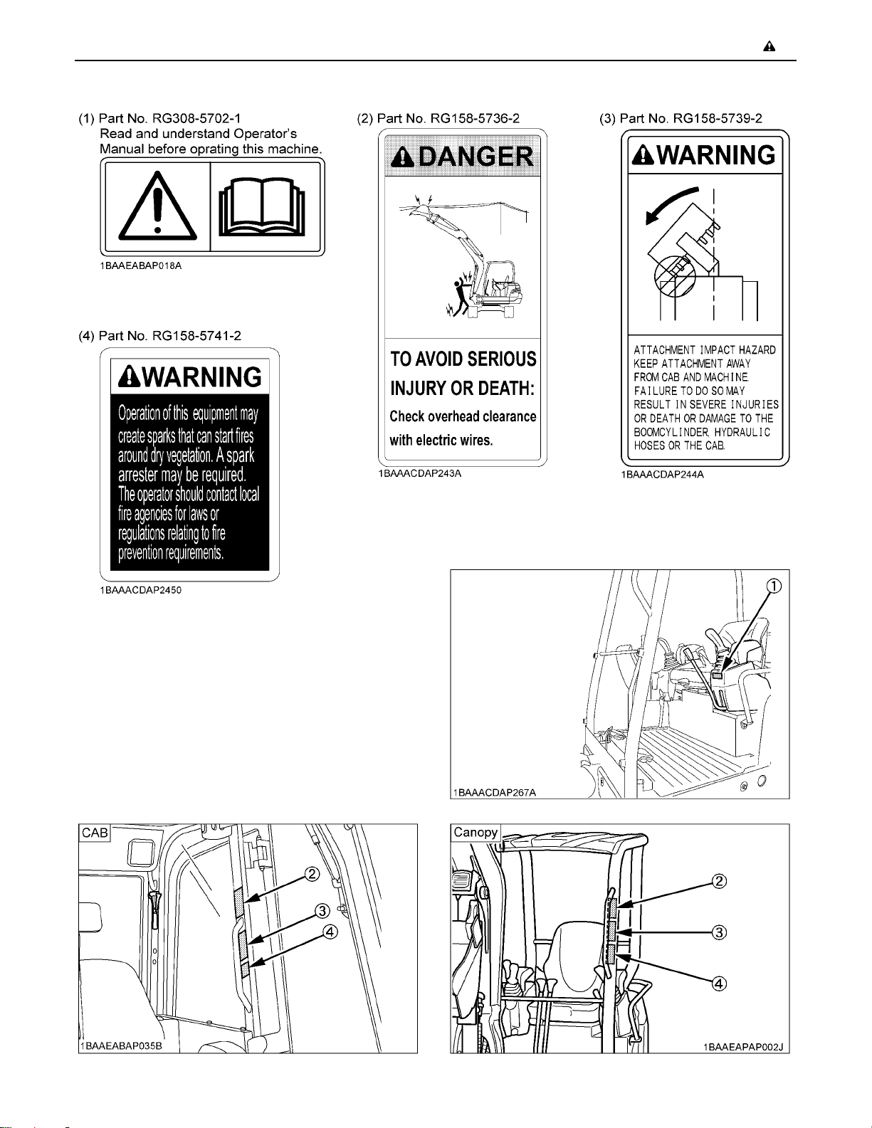
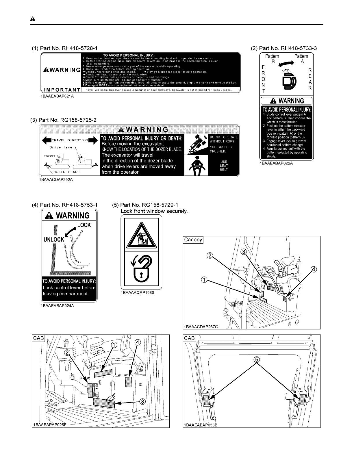
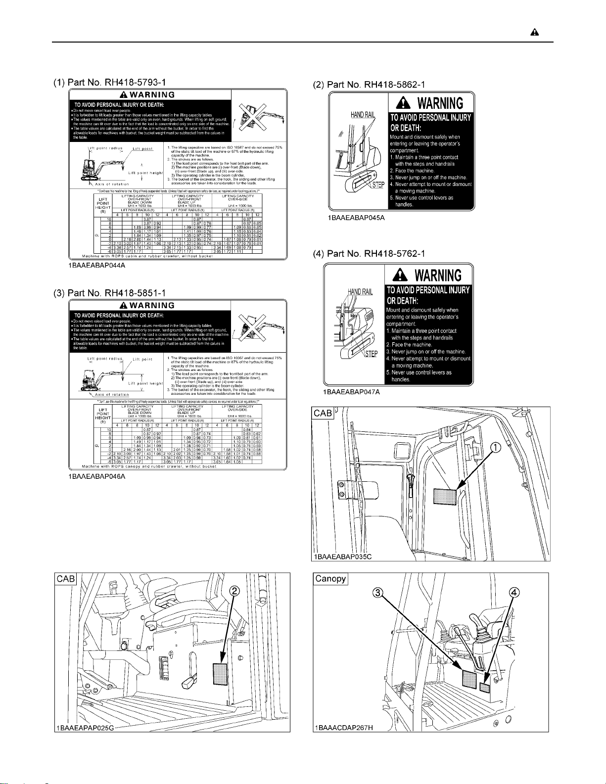
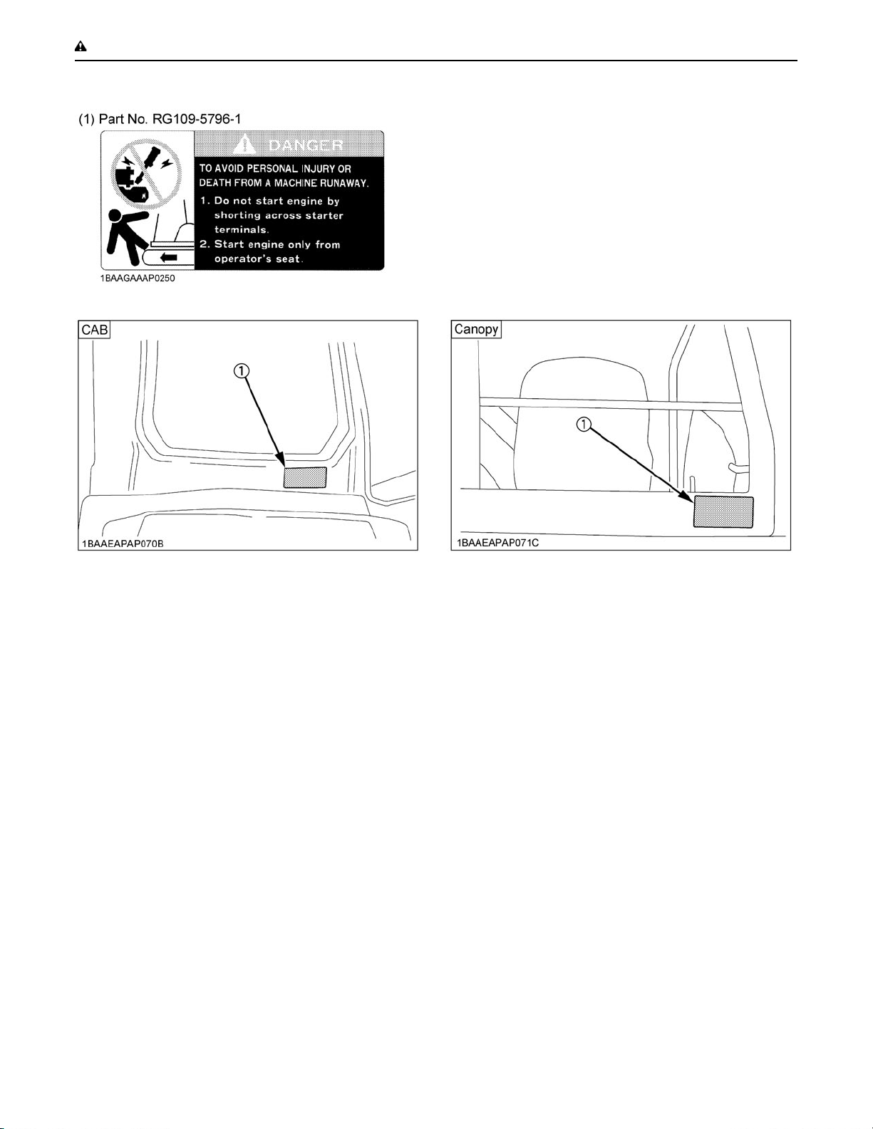
6. DANGER, WARNING AND CAUTION LABELS
Keep the safety and warning symbols (labels ) on the excavator clean and legible, replacing them if necessary.
The positioning of the safety symbols is illustrated in the following figures.
Page 17
-9SAFE OPERATION
Page 18
SAFE OPERATION-10
Page 19
-11SAFE OPERATION
Page 20
SAFE OPERATION-12
Page 21
-13SAFE OPERATION
Page 22
SAFE OPERATION-14
7. CARE OF DANGER, WARNING AND CAUTION LABELS
1. Keep danger, warning and caution labels clean and free from obstructing material.
2. Clean danger, warning and caution labels with soap and water, and dry with a soft cloth.
3. Replace damaged or missing danger, warning and caution labels with new labels from your KUBOTA dealer.
4. If a component with danger, warning and caution label(s) affixed is replaced with new part, make sure new label(s) is
(are) attached in the same location(s) as the replaced component.
5. Mount new danger, warning and caution labels by applying on a clean dry surface and pressing any bubbles to outside
edge.
Page 23
DEALER SERVICE
Your KUBOTA dealer is always ready to help so that your
excavator offers the best performance. After having
carefully read these instructions, you will realize that
much of the routine maintenance can be done by yourself.
For service, contact the KUBOTA Dealer shop from which
you purchased your product, or your local KUBOTA
dealer. When ordering spare parts from your KUBOTA
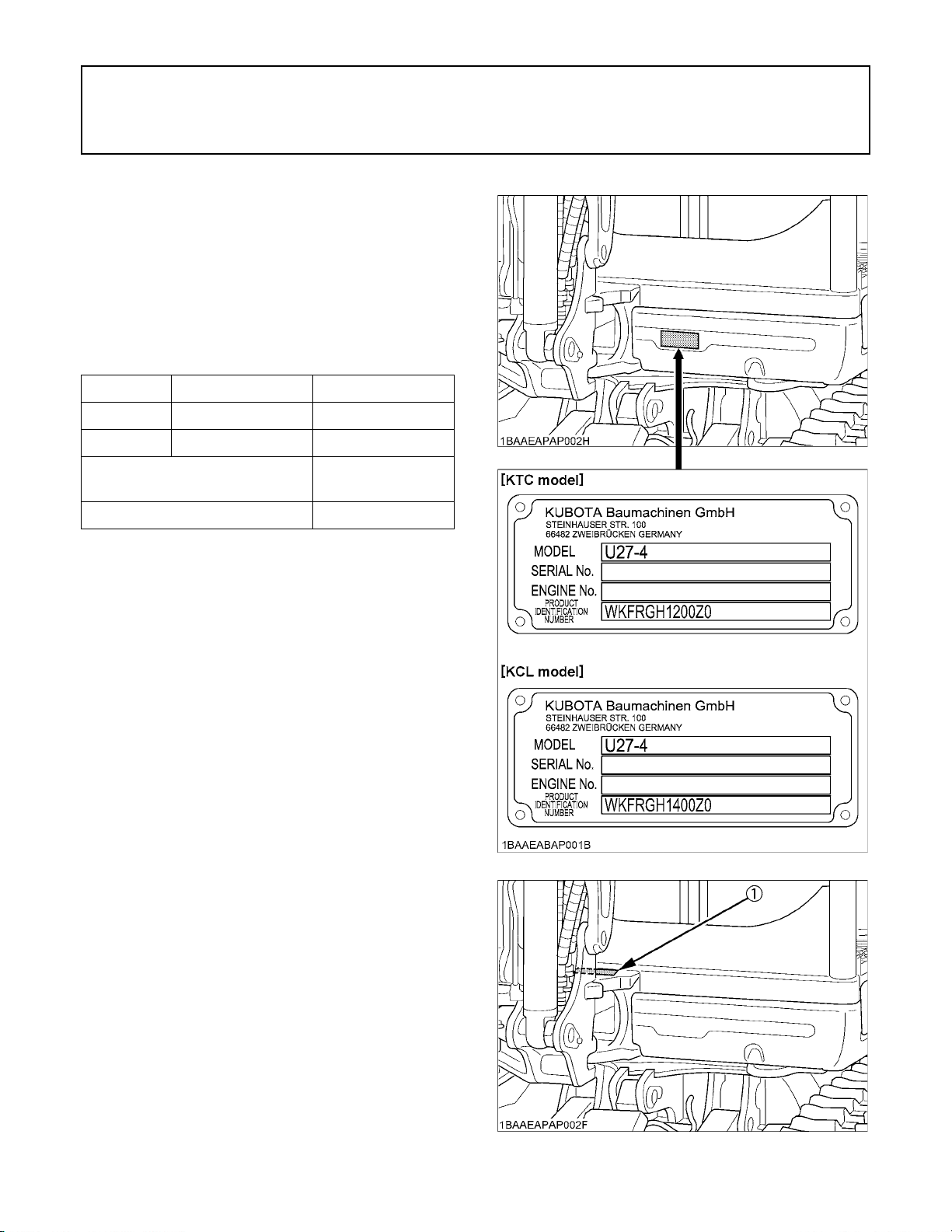
dealer, always mention the serial number of the excavator
and the engine.
Note these numbers right away in the supplied lines.
Model Serial No.
Excavator
Engine
Dealer's name
(To be filled in through the owner)
1DEALER SERVICE
Date of purchase
C Warranty policy
This product is warranted under the KUBOTA Limited
Express Warranty, a copy of which may be obtained from
your selling dealer. No warranty shall, however, apply if
the product has not been handled according to the
instruction given in the Operator's Manual even it is within
the warranty period.
The Product(s) described in this Operator’s Manual are
designed and manufactured only for the country in which
they are initially wholesaled by KUBOTA or one of its
affiliated companies. Neither KUBOTA Corporation nor its
affiliated companies provide warranty for any Product
which is re-sold or retailed in any country other than the
country for which the Product(s) were designed or
manufactured.
C Scrapping the product and its procedure
To put the product out of service, correctly follow the local
rules and regulations of the country or territory where you
reside. If you have questions, consult your local KUBOTA
Dealer.
(1) Serial No.
Page 24
DEALER SERVICE2
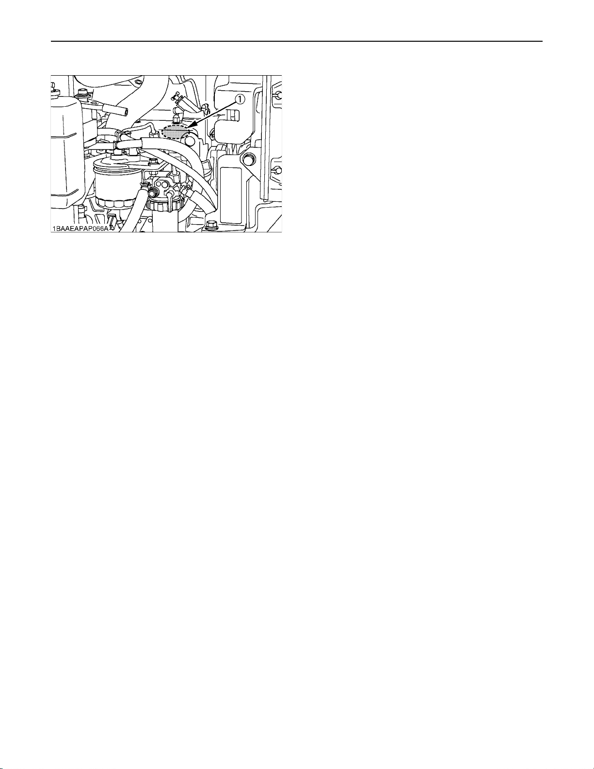
(1) Engine serial No.
Page 25
TECHNICAL DATA
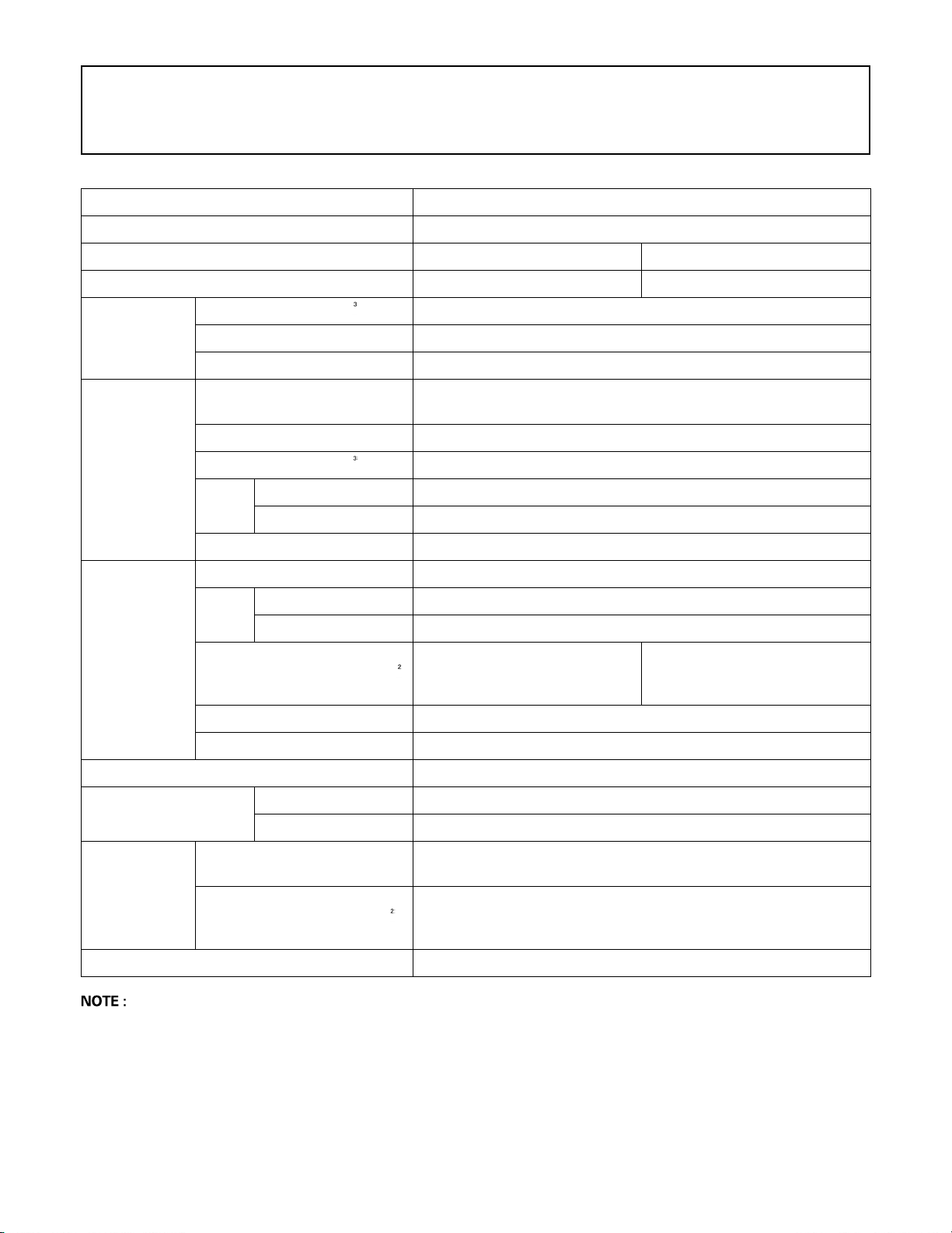
KUBOTA EXCAVATOR
Model name U27-4
Type canopy cabin
Mass (without operator) kg (lbs.) 2490 (5490) 2590 (5711)
Volume (CECE) m (cu.in.) 0.054 (3295)
Standard
bucket
Width [with side cutter] mm (in.) 450 [475] (17.7 [18.7])
Weight kg (lbs.) 55 (121)
3TECHNICAL DATA
Type
(water cooled 4 cycle Diesel)
Model name KUBOTA D1105-E4-BH-5
Engine
Performance
Dozer (width & height) mm (in.) 1500 x300 (59 x 12)
Boom swing angle
Total displacement cm (cu.in.) 1123 (68.5)
Output
Rated speed rpm 2400
Swing speed rpm 9.9
Travel
speed
Ground pressure kPa
(kgf/cm )
[psi]
Climbing angle % (deg) 27 (15)
Max. lateral sway % (deg) 18 (10)
SAE gross kW (HP) 15.6 (20.9)
SAE Net kW (HP) 14.8 (19.8)
fast km/h (mph) 4.5 (2.8)
slow km/h (mph) 2.5 (1.6)
Left rad (deg) 1.31 (75)
Right rad (deg) 0.96 (55)
3 cylinder - diesel engine water cooled
23.7
(0.24)
[3.44]
24.7
(0.25)
[3.58]
Max. displacement
Pressure
connection
for attachments
Fuel tank capacity L (US gal) 33 (8.72)
A Above dimensions are based on the machine with JPN bucket.
JPN = made in Japan
A Above dimensions are based on the machine with rubber crawlers.
A Specifications subject to change without notice.
L (US gal) / min
Max. pressure MPa
(kgf/cm )
[psi]
48.0 (12.7)
21.6
(220)
[3133]
Page 26
4 DESCRIPTION OF MACHINE PARTS
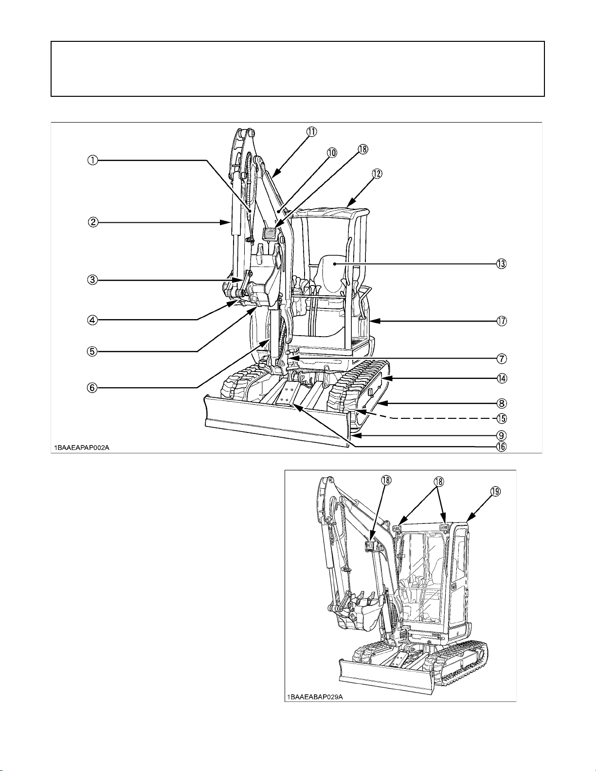
DESCRIPTION OF MACHINE PARTS
[Canopy]
DEPICTED CONTENTS
(1) Arm
(2) Bucket cylinder
(3) Bucket link 2
(4) Bucket link 1
(5) Bucket
(6) Boom cylinder
(7) Swing bracket
(8) Crawler
(9) Dozer
(10) Boom
(11) Arm cylinder
(12) ROPS
(13) Operator's seat
(14) Drive sprocket
(15) Front idler
(16) Dozer cylinder
(17) Engine hood
(18) Working light
(19) Cabin
[Cabin]
Page 27
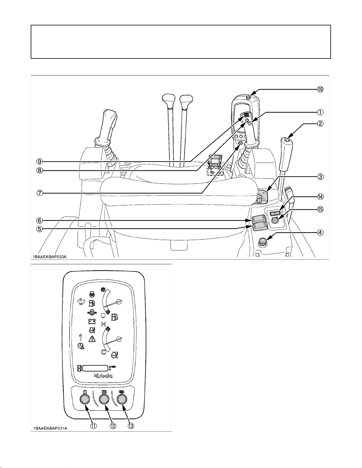
5INSTRUMENT PANEL AND CONTROL ELEMENTS
INSTRUMENT PANEL AND CONTROL ELEMENTS
B Switches
DEPICTED CONTENTS
(1) One way hold switch............................................
(2) Travel speed switch.............................................
(3) Starter switch.......................................................
(4) Engine stop button...............................................
(5) Beacon light switch..............................................
(6) Working light switch.............................................
(7) Indicator for auxiliary port.....................................
(8) Horn switch..........................................................
(9) Rocker switch for auxiliary port............................
(10) Potentiometer for auxiliary port..........................
(11) Enable switch for auxiliary port (switch 1)..........
(12) User setting switch (switch 2)............................
(13) Display selector switch (switch 3)......................
[Cab model]
(14) Wiper / washer switch........................................
(15) Heater switch.....................................................
Ref. page
27
30
12
19
22
9, 22
26
12
26
34
26
13
13
8
9
Page 28
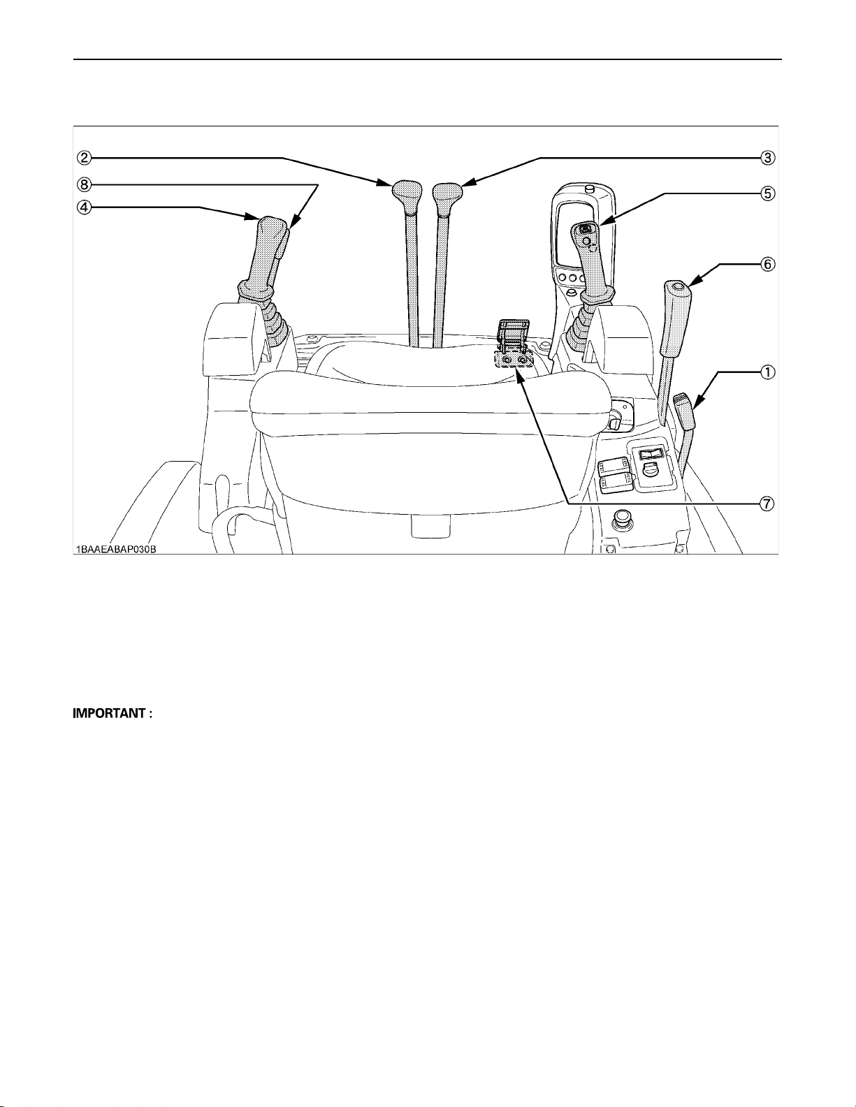
6 INSTRUMENT PANEL AND CONTROL ELEMENTS
B Control Pedals and Levers
DEPICTED CONTENTS
(1) Throttle lever........................................................
(2) Drive lever (left)....................................................
(3) Drive lever (right)..................................................
(4) Control lever for front attachments (left)...............
(5) Control lever for front attachments (right).............
(6) Dozer control lever................................................
(7) Boom swing pedal.................................................
(8) Pilot control lock lever *.........................................
Ref. page
29
29
29
24, 24, 25
24, 24, 25
26
25
11
D Pulling up the pilot control lock lever prevents inadvertent machine movement.
Page 29
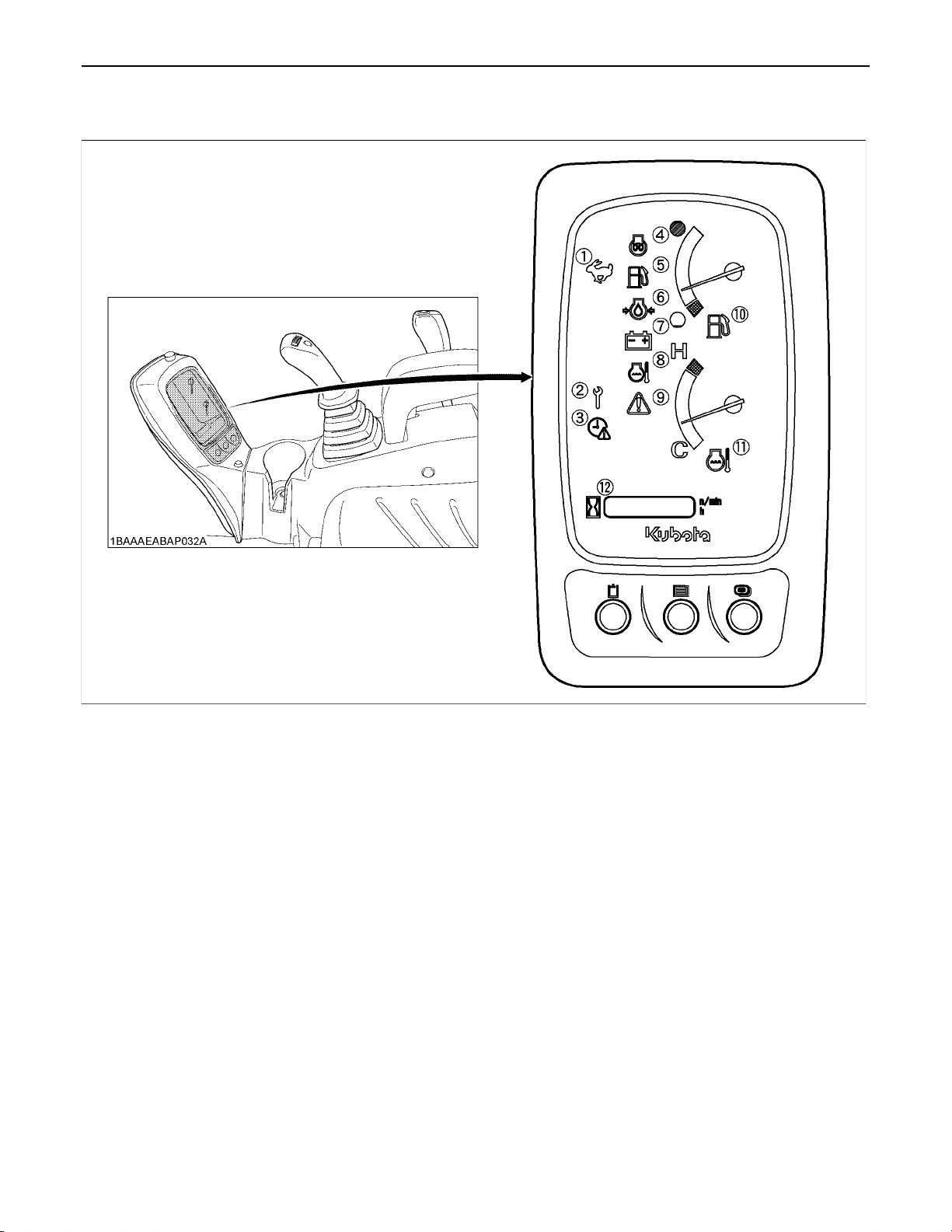
B Instrument Panel
7INSTRUMENT PANEL AND CONTROL ELEMENTS
DEPICTED CONTENTS
(1) Travel speed indicator lamp.................................
(2) Periodic check lamp.............................................
(3) Clock setting request lamp...................................
(4) Glow lamp.............................................................
(5) Remaining fuel warning lamp................................
(6) Engine oil pressure warning lamp.........................
Ref. page
30
66
13
15
16
15
(7) Battery charge lamp..............................................
(8) Coolant temperature warning lamp.......................
(9) Warning lamp........................................................
(10) Fuel gauge..........................................................
(11) Coolant temperature gauge................................
(12) LCD....................................................................
Ref. page
15
16
17
16
16
16
Page 30
8 CHECKS BEFORE START
CHECKS BEFORE START
DAILY CHECKS
In order to avoid damage, it is important to check the
condition of the excavator before starting.
To avoid personal injury or death:
A Do maintenance work on the excavator only on
even ground with the engine off and the pilot
control lock lever in the "LOCKED" position.
Checks
Go around the excavator and check for visual damage
and wear.
Check coolant level. (See "DAILY CHECKS" in
"MAINTENANCE" section.)
Check fuel level.
Check engine oil level.
Check hydraulic fluid level.
Check air filter for clogging.
Check all greasing points.
Check all control lamps, indicators, revolution counter and
hour meter.
Confirm all controls move freely and do not stick.
Check the light system.
Check the seat belt and the ROPS/OPG (Top Guard Level
I) safety device.
Check the condition of the safety and warning labels. (See
"DANGER, WARNING AND CAUTION LABELS" in
"SAFE OPERATION" section.)
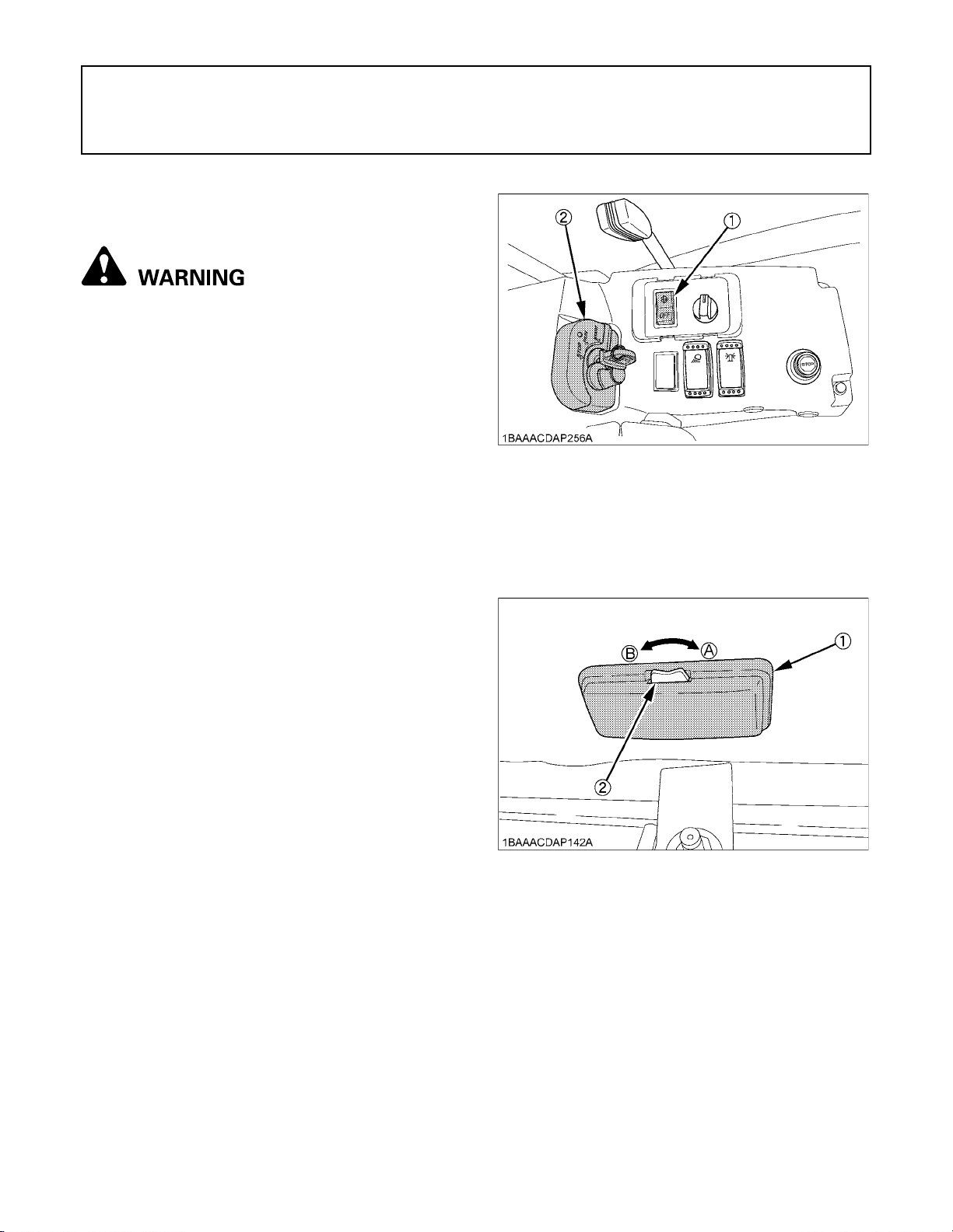
(1) Wiper / Washer switch
(2) Starter switch
BInterior Lamp
To turn on the interior lamp, set the interior lamp switch to
the "ON" position.
CAB TYPE MACHINES
BWiper/Washer Switch
To move the wiper, turn on the switch for the wiper when
the starter switch in position "RUN". A further push on the
switch will activate the washer system. Even when the
wiper switch is in position "OFF", the washer switch
functions if it is pressed.
A Do not activate the washer switch if the tank for the
cleaning fluid is empty; the pump can be damaged.
A Do not activate the wiper switch if the window is dry. In
this case, make sure that cleaning fluid is applied to
the pane before activating the wiper.
A In frosty conditions, make sure that the wiper blade is
not frozen to the glass before switching-on. The motor
can be damaged if the wiper system is used under
such conditions.
(1) Interior lamp
(2) Interior lamp switch
(A) "ON"
(B) "OFF"
Page 31
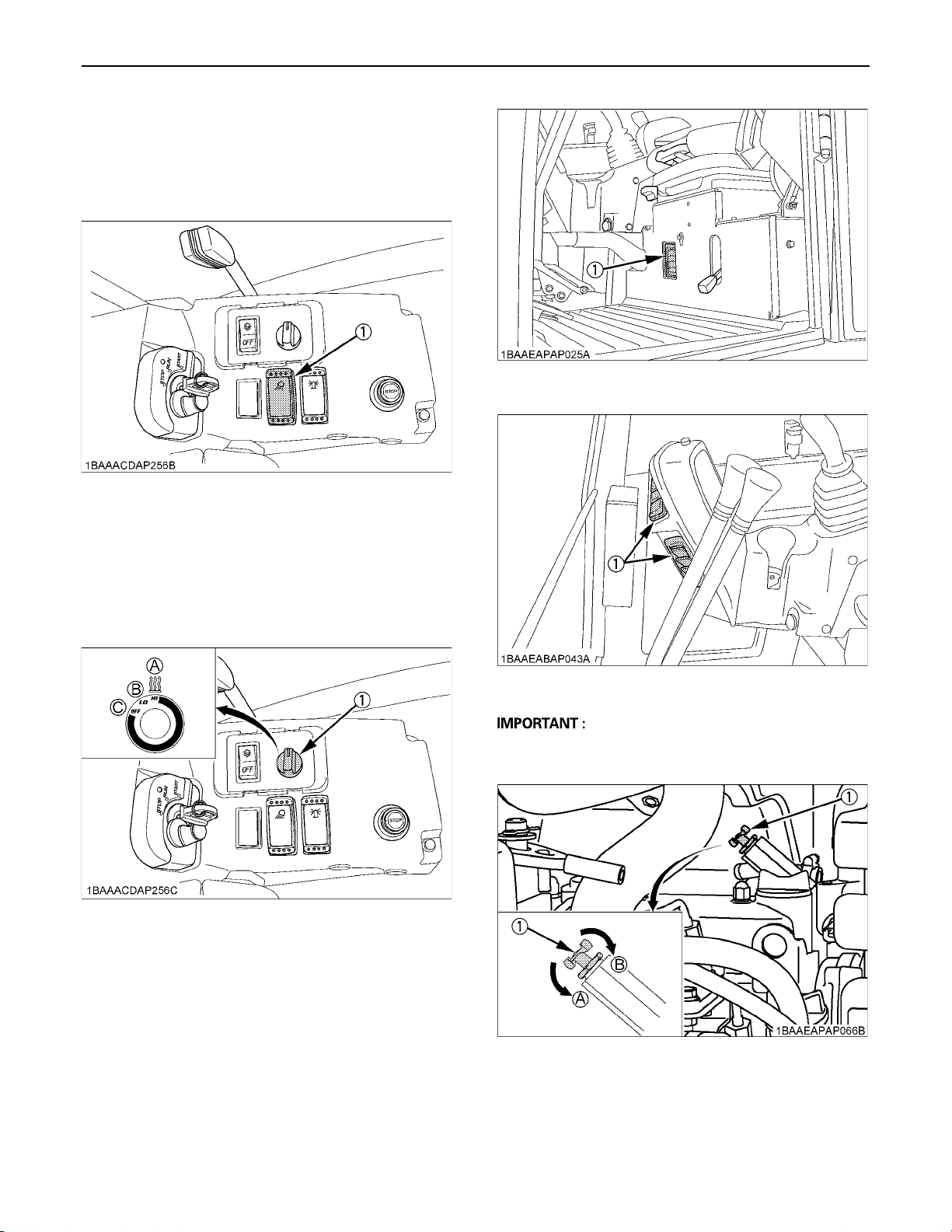
BWorking Light Switch
To turn on the working light, set the starter switch to the
"RUN" and then the working light switch to the "ON"
positions, respectively.
(1) Working light switch
9CHECKS BEFORE START
(1) Heater outlet
BHeater Switch
Turn the starter switch to position "RUN" and turn the
heater switch clockwise, the heater fan will be activated
and the CAB will start to warm up. The heater has two
positions - "Low" and "High" -.
(1) Heater switch (A) Pos. "High"
(B) Pos. "Low"
(C) Pos. "Off"
(1) Heater outlet
A During the summer, turn the heater valve clockwise to
close the valve.
(1) Heater valve (A) Open
(B) Close
Page 32
CHECKS BEFORE START10
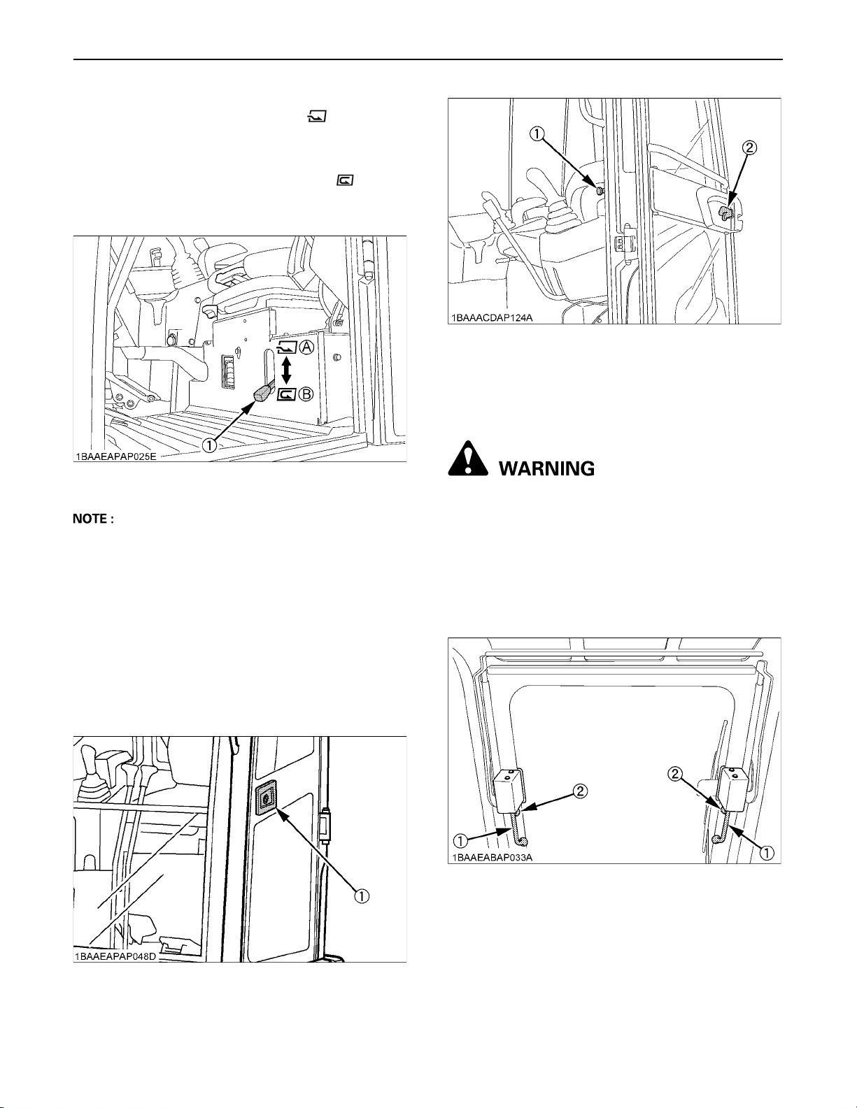
C Recirculation / Fresh Air Selection knob
A FRESH AIR: Set the knob to the position, and
fresh air will flow into the CAB. This is helpful when you
work in a dusty conditions or if the glass windows get
foggy.
A RECIRCULATION: Set the knob to the position,
and the in-CAB air will be recirculated.This is useful for
heating the CAB quickly or keeping it extra warm.
(1) Release lever
(2) Door knob (inside)
3. When leaving the excavator, always lock the door.
BOpening/Closing of Front CAB Window
(1) Recirculation/
fresh air selection knob
(A) "FRESH AIR"
(B) "RECIRCULATION"
A When heating, do not keep the knob at the
"RECIRCULATION" position for a long time. The
windshield easily gets foggy.
A While working in a dusty condition, keep the knob at
the "FRESH AIR" position.
BOpening/Closing of CAB Door
1. Unlock the CAB door and pull the knob. Open the CAB
door fully until fixed into place.
2. To close the CAB door, push the release lever down
and close the door.
To avoid personal injury or death:
A Keep hands and feet away from the area
between front window and CAB frame.
Otherwise the operator risks serious pinching
or crushing injuries.
A Other persons should stay away when opening
the window.
To open and close the front window, take the steps below.
1. Push the lock levers beside grip.
(1) Grip
(2) Lock lever
(1) Door knob (outside)
2. Hold the grips tightly with both hands. Pull the grip
slightly upward and toward yourself to let the
windshield slide inward.
3. Pull the windshield all the way to the lock at the back
of CAB.
4. To close the window, take the reverse steps 3, 2 and 1.
Page 33
11CHECKS BEFORE START
BOpening/Closing of Side CAB Window
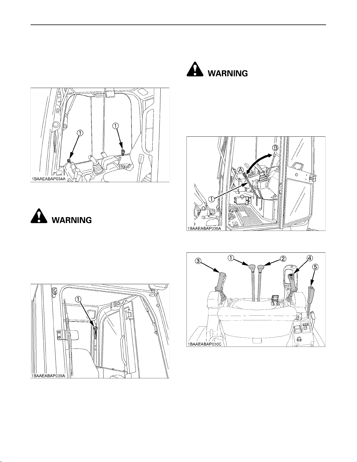
1. Pull the grip to release the lock and pull side window
open to the rear or to the front.
2. To close the side window, slide it forward or backward
until the lock snaps in at the window frame.
(1) Grip
BEmergency Hammer
HANDLING THE SAFETY DEVICES
BPilot Control Lock Lever
To avoid personal injury or death:
A When the excavator is not used or left
unattended, be sure to place the pilot control
lock lever in position "LOCKED".
If the pilot control lock lever is raised in position
"LOCKED" completely, then the hydraulic functions of the
following controls will be locked.
To avoid personal injury or death:
A When breaking the window pane, close your
eyes and cover them with an arm.
The emergency hammer is for breaking rear window pane
to escape from excavator should escape from the left side
door, front window pane or right window pane is not
possible.
(1) Emergency hammer
(1) Pilot control lock lever (A) "UNLOCK"
(B) "LOCKED"
(1) Drive lever (Left)
(2) Drive lever (Right)
(3) Control lever for attachments (Left)
(4) Control lever for attachments (Right)
(5) Dozer control lever
Page 34
12 OPERATION OF THE ENGINE
OPERATION OF THE ENGINE
To avoid personal injury or death:
A Read "SAFE OPERATION" at the beginning of
this operator's manual.
A Obey the danger, warning and caution labels
on the excavator.
A To avoid the danger of exhaust fume (carbon
monoxide) poisoning, do not operate the
machine in a closed building without proper
ventilation.
A Always start the engine from the operator's
seat. Do not start the engine while standing
next to the excavator. Before starting the
engine, sound the horn to get the attention of
persons standing nearby.
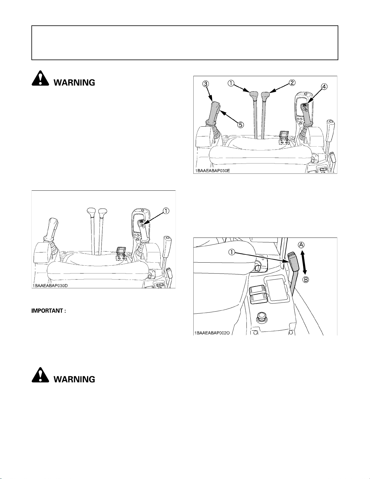
(1) Drive lever (left)
(2) Drive lever (right)
(3) Attachment control lever (left)
(4) Attachment control lever (right)
(5) Pilot control lock lever
2. Pull the pilot control lock lever all the way back.
("LOCKED" position)
A Put the throttle lever towards the "SLOW" position.
(1) Horn switch
A Do not use starting fluid or ether.
A In order not to overload the battery and starter, avoid
engaging the starter more than 10 sec.
A When engine does not start in 10 sec., please wait 20
sec. or more, before attempting to restart.
STARTING THE ENGINE
To avoid personal injury or death:
A The operator should not depend solely on the
warning lamps, but should always conduct the
routine checks (see "MAINTENANCE").
Start the engine in the following manner:
1. Before starting the engine, make sure that all control
levers are in the neutral positions.
(1) Throttle lever (A) "FAST"
(B) "SLOW"
3. Insert the key into the starter switch and turn it to the
position "RUN". The glow lamp indicator will light up
while the engine is preheated and will go out
automatically after preheating is finished.
Page 35
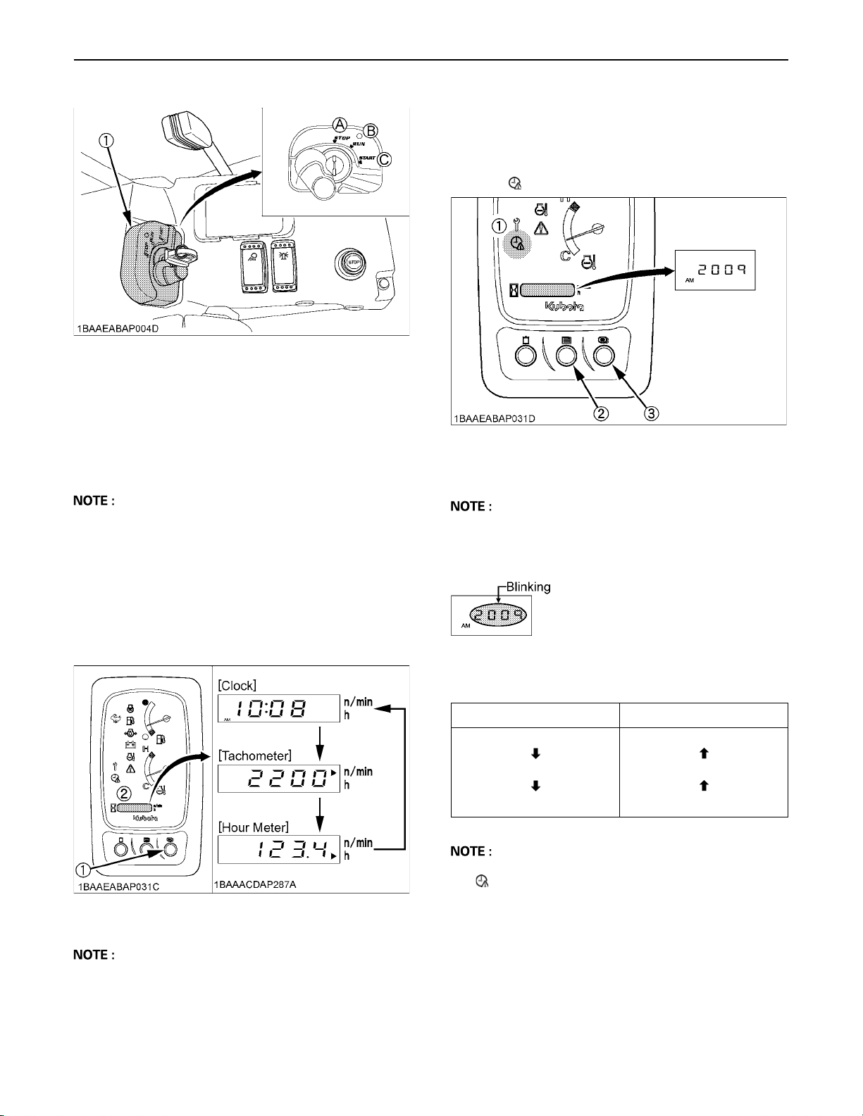
(1) Starter switch (A) "STOP"
(B) "RUN"
(C) "START"
4. Turn the key to the position "START" and release after
the engine has started.
5. Check if oil lamp and charge lamp have gone out.
Should a warning lamp still be lit up, stop the engine
then remove the key and check for the cause.
13OPERATION OF THE ENGINE
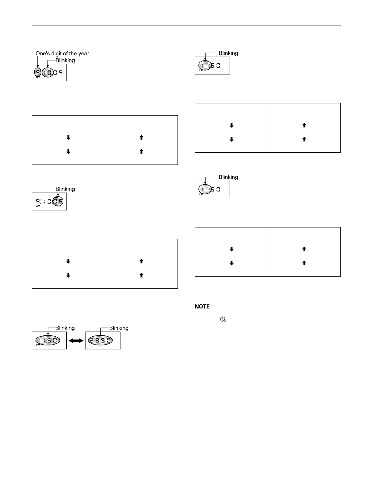
C Setting the clock
[Selecting the clock setting mode]
1. Press the user setting switch (switch 2).
2. Select the clock setting mode by pressing the display
selector switch (switch 3) and the clock setting request
lamp " " on the instrument panel lights up.
(1) Clock setting request lamp
(2) User setting switch (switch 2)
(3) Display selector switch (switch 3)
A When the pilot control lock levers are in "UNLOCK"
position, the engine does not start.
BDisplay Selector Switch
Press the display selector switch. The electronic meter's
LCD will change from one indication mode to the other.
Change the three-mode display according to your jobs.
(1) Display selector switch
(2) LCD
A Press switch 3 for a long time and the year, month,
day, hour and minute will be selected in this order.
[Setting the year]
Press switch 2 and the numeric setting will be smaller.
Press switch 3 and the numeric setting will be larger.
Switch 2 Switch 3
2008
2007
2006
2010
2009
2008
A While setting the clock, the clock setting request lamp
" " on the instrument panel is blinking.
A With the starter key at the "STOP" position, press the
electronic meter's display selector switch, and the LCD
shows the hour meter, fuel gauge and water
temperature gauge for 10 seconds.
Page 36
OPERATION OF THE ENGINE14
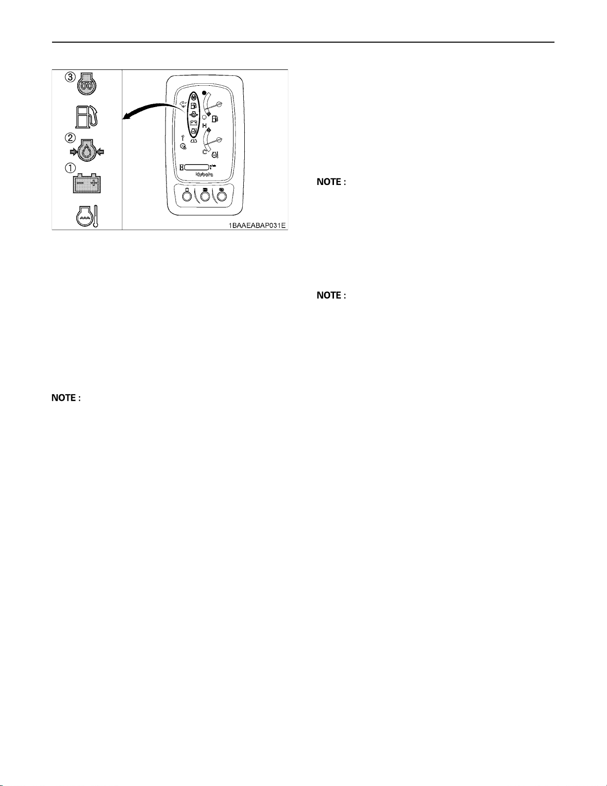
[Setting the month]
Press switch 2 and the numeric setting will be smaller.
Press switch 3 and the numeric setting will be larger.
Switch 2 Switch 3
10
9
8
[Setting the day]
Press switch 2 and the numeric setting will be smaller.
Press switch 3 and the numeric setting will be larger.
11
10
9
[Setting the hour]
Press switch 2 and the numeric setting will be smaller.
Press switch 3 and the numeric setting will be larger.
Switch 2 Switch 3
11
10
9
[Setting the minute]
Press switch 2 and the numeric setting will be smaller.
Press switch 3 and the numeric setting will be larger.
Switch 2 Switch 3
12
11
10
Switch 2 Switch 3
09
08
07
[Changing the AM/PM system to the 24-hour system]
Select the AM/PM system or 24-hour system by pressing
switch 3.
11
10
9
50
49
48
If switch 3 is pressed for a long time, the new settings will
be made.
A If the battery is disconnected, the clock setting request
lamp " " (yellow) will blink for requesting the setting
the clock.
52
51
50
Page 37
15OPERATION OF THE ENGINE
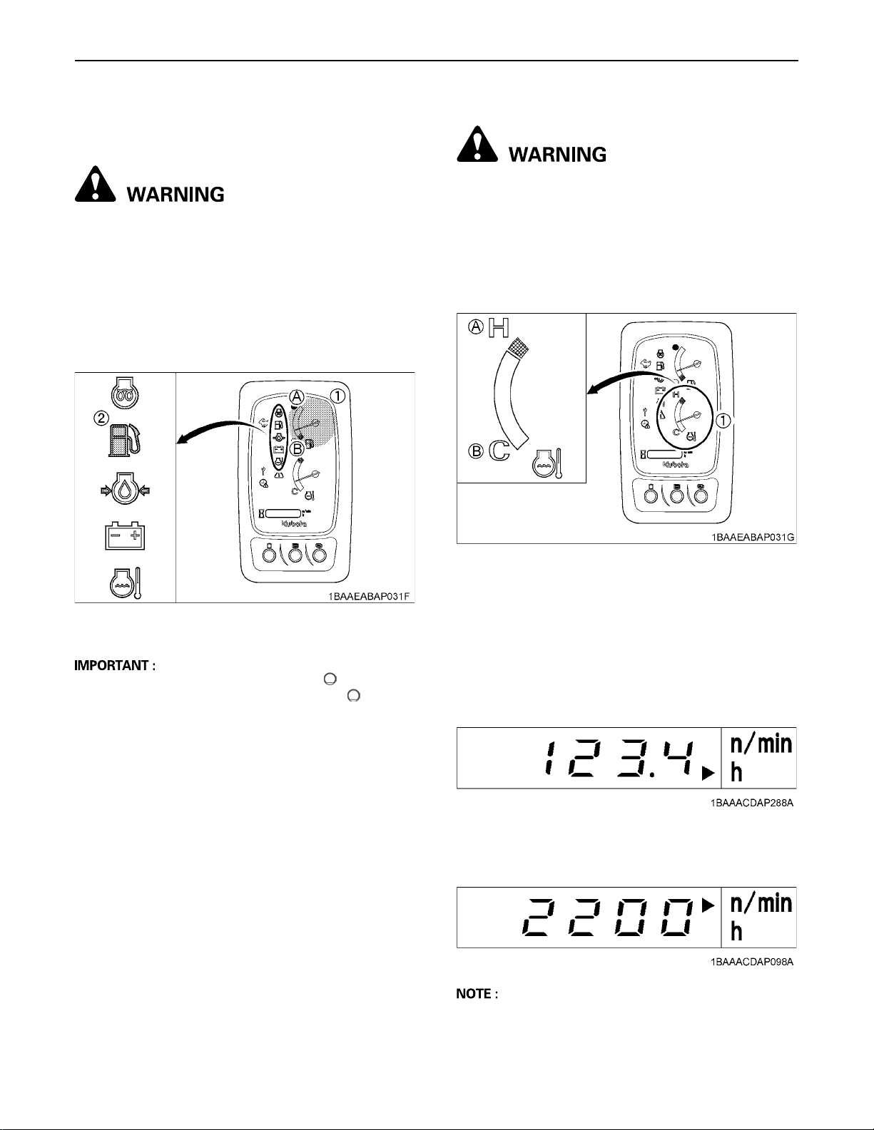
BEngine Oil Pressure Warning Lamp
The engine oil pressure warning lamp lights up due to
failure of the lubricating system with the engine running.
When the starter switch is turned to "RUN" with the
engine off, this lamp lights up, and when the engine starts,
the lamp goes out. If the lamp stays on with the engine
running, stop the engine and check the engine oil level.
A If there is disconnection, failure or breakdown in the
lubricating system when the key is turned to "RUN",
the following symbol will appear.
(1) Battery charge lamp
(2) Engine oil pressure warning lamp
(3) Glow lamp
BBattery Charge Lamp
This warning lamp lights up if the charging system fails
with the engine running. When the starter switch is turned
to "RUN" with the engine off, the lamp lights up, and when
the engine starts, the lamp goes out. If the lamp stays on
with the engine running, stop the engine and check the fan
belt.
A If there is disconnection or failure in the charging
system when the key is turned to "RUN", the following
symbol will appear.
BGlow Lamp
With the starter key at the "RUN" position, the engine's
preheat status is indicated.
A When the starter switch is turned to the "RUN"
position, the engine will be preheated for a given
period of time and the indicator will turn on.
A The above indication appears momentarily when the
engine is started, but it does not indicate trouble. (This
is because the oil charge sensor output fluctuates
when the engine is started.)
A The following symbol appears momentarily as the
engine starts. This is not an error.
Page 38
OPERATION OF THE ENGINE16
BLCD for Normal Operation
C Fuel gauge
To avoid personal injury or death:
A Before adding fuel, be sure to stop the engine.
A Be sure to keep open flame away from the
machine. Otherwise a fire may result.
If the fuel in the tank goes below the prescribed level, the
warning lamp will flash.
If this should happen during operation, refuel as soon as
possible.
C Coolant Temperature Gauge
To avoid personal injury or death:
A Do not open the radiator cap during or just after
operation. Hot coolant may gush out and scald
you. Wait for the coolant to cool down before
opening the cap.
With the starter key at the "RUN" position, the cooling
water temperature is indicated.
(1) Fuel gauge
(2) Remaining fuel warning lamp
(A) "FULL"
(B) "EMPTY"
A If the fuel gauge indicator is near the "", add fuel as
soon as possible. If the indicator is near "" and the
machine operates on a slope, the engine may run out
of fuel.
(1) Coolant temperature gauge (A) "HOT"
(B) "COOL"
C Hour-meter
Indicates the total operating hours of the machine.
How the indicator works
A The meter advances one hour after an hour of
operation regardless of the engine rpm.
C Engine tachometer
Indicates the current rpm of the engine.
A The LCD may be illegible when viewed from a certain
angle. This is not a display failure.
Page 39
17OPERATION OF THE ENGINE
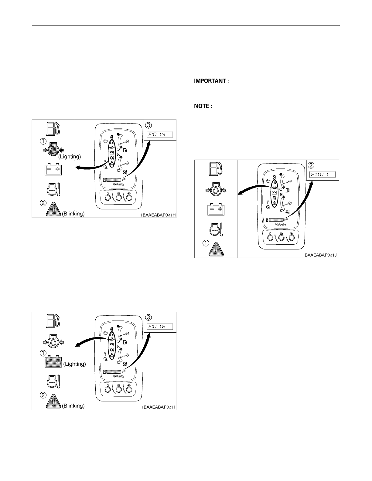
BLCD for Warning
C Engine oil pressure warning lamp
The engine oil pressure warning lamp lights up due to
failure of the lubricating system with the engine running.
When the starter key is turned to "RUN" position with the
engine off, this engine oil pressure lamp lights up, warning
lamp blinks and when the engine starts, the lamps go out.
If the lamp stays on with the engine running, stop the
engine and check the engine oil level.
(1) Engine oil pressure lamp
(2) Warning lamp (red)
(3) Warning message
BWarning Lamp
The warning lamp is used to indicate broken wire, shortcircuit, fuel shortage and other problems.
A Do not just look at the meter, but also carry out the
inspection and correction accordingly.
A The warning lamp starts flashing in red if a serious
problem occurs. If the system gets in warning signal,
the warning lamp starts flashing in yellow.
A Warnings and errors are displayed and an alarm
buzzer beeps.
A Let your KUBOTA dealer inform you of details
concerning care and maintenance.
C Battery charge lamp
This battery charge lamp lights up if the charging system
fails with the engine running.
When the starter key is turned to "RUN" position with the
engine off, the battery charge lamp lights up, warning
lamp blinks and when the engine starts, the lamps go out.
If the lamp stays on with the engine running, stop the
engine and check the V-belt.
(1) Battery charge lamp
(2) Warning lamp (red)
(3) Warning message
(1) Warning lamp
(2) Warning message
Page 40
OPERATION OF THE ENGINE18
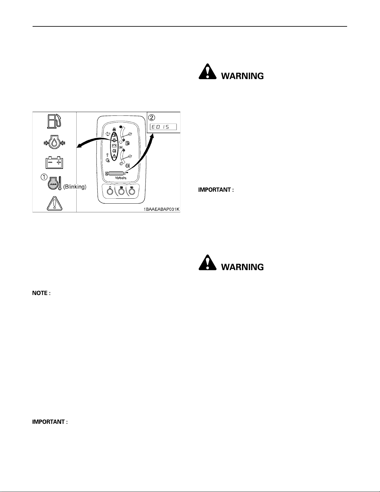
C Overheat warning
1. If the coolant temperature becomes elevated, the
coolant temperature warning lamp blinks and the
warning message (E: 015) appears on LCD. The
message fades out after a short time and the coolant
temperature warning lamp blinks as long as the
temperature remains elevated. Operate the machine
only with reduced loads until the operating
temperature is normal again.
(1) Coolant temperature warning lamp
(2) Warning message
STARTING THE ENGINE UNDER COLD CONDITIONS
To avoid personal injury or death:
A Make sure that the pilot control lock lever is in
the "LOCKED" position during warm up.
Start the engine in the following manner;
1. Pull the pilot control lock levers all the way back (lock
position).
2. Turn the starter switch to the position "RUN" (glow
position) and keep until the indicator lamp has gone
out.
3. Move the starter switch to the position "START" to
crank and start engine.
4. Release the starter switch after the engine has started;
it will automatically return to the position "RUN".
A Let the engine warm up after start-up for approx. 10
minutes under no load conditions. If the hydraulic fluid
temperature is too low, the operation will be affected.
Do not operate the excavator under full load until the
engine has sufficiently warmed up.
BCheckpoints after Starting the Engine
After starting the engine, but before starting operation,
check the following points:
1. Put the throttle lever in position "SLOW" and let the
engine idle for approx. five minutes. This allows the
engine lubricant to warm up and penetrate every part
of the engine.
A This idling is usually called "Warm-up".
2. Once the engine has warmed up, check:
A the warning lamp "Engine oil pressure" has gone
out.
A the warning lamp "Battery charge" goes out when
engine speed is increased.
A the color of the exhaust is normal and no abnormal
noises or vibrations are heard or felt.
A no fluid is leaking from pipes or hoses.
C Should any following conditions occur, stop the
engine immediately.
A The engine rpm's increases or decreases suddenly.
A Sudden abnormal noises are heard.
A Exhaust is black.
A Warning lamp for engine oil lights up during operation.
BPrecautions in case of Overheat
To avoid personal injury or death:
A Do not open the radiator cap during operation
or just after shut-down. Otherwise, steam or
very hot coolant may gush out, getting you
scalded. Make sure the radiator has cooled
down enough before opening its cap.
If coolant gets heated up to the boiling point or over
(overheated), take the following steps.
1. Stop operation in a safe position.
(Disconnect the engine's load.)
2. Do not stop the engine suddenly. Keep the engine
idling under no load for about 5 minutes and then turn
it off.
3. Keep yourself enough away from the machine for
another 10 minutes or while steam is emitting.
4. Make sure there is no hazard of getting burned. Check
and remove the cause of overheat, referring to
"TROUBLESHOOTING". Then restart the engine.
A In these cases, the excavator must be checked and
serviced by your local the KUBOTA dealer.
Page 41
19OPERATION OF THE ENGINE
STOPPING THE ENGINE
To avoid personal injury or death:
A Do not keep the bucket or dozer in the lifted
position, as a person could accidentally touch
the levers and cause serious accidents.
1. Place the bucket and dozer on the
ground.
2. After slowing the engine to idle, turn
the key to "STOP".
3. Remove the key.
4. Pull the pilot control lock lever to
"LOCKED" position.
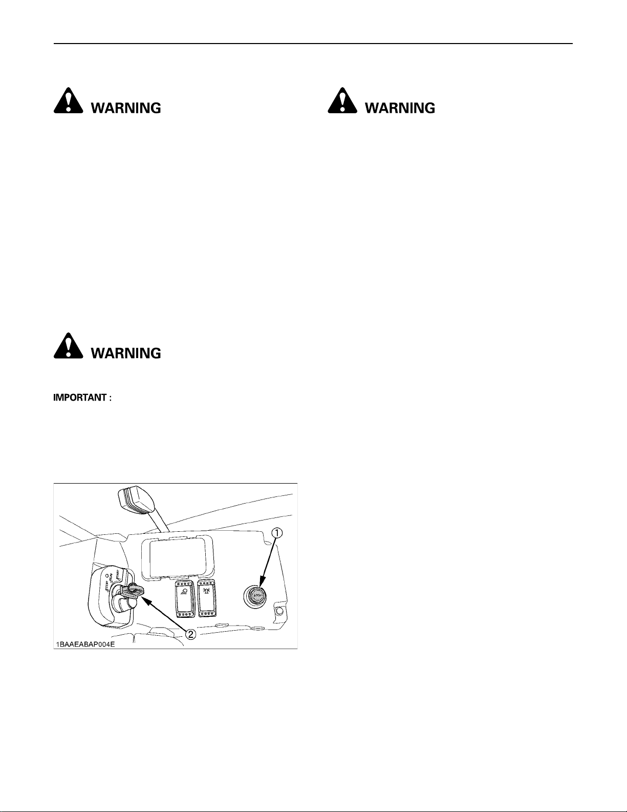
BEngine Stop Button
To avoid personal injury or death:
A Keep hands away from rotating parts.
A Be sure to return the stop button to former position
after the engine stops.
The engine stops when the key is turned off. If the engine
does not stop, pull back the stop button and hold it until
the engine stops.
STARTING WITH AN AUXILIARY BATTERY
To avoid personal injury or death:
A Battery gases can explode.
Do not smoke and keep sparks and flames
away.
A Do not start the engine with an auxiliary battery
if excavator battery is frozen.
A Do not connect the black jumper cable to the
negative (-) terminal of the excavator battery.
BObserve Following Guidelines when
Starting with an Auxiliary Battery
1. Bring the helping machine with the same battery
voltage as near as possible to the excavator.
THE MACHINES MUST NOT COME IN CONTACT
WITH EACH OTHER.
2. Bring the levers and pedal of both vehicles in the
neutral position and put the pilot control lock lever in
the "LOCKED" position.
3. Wear eye protection and rubber gloves.
4. Open the side cover. (See "Opening/Closing of the
Side Cover" in "MAINTENANCE" section.)
5. Ensure the vent caps are securely in place (if
equipped).
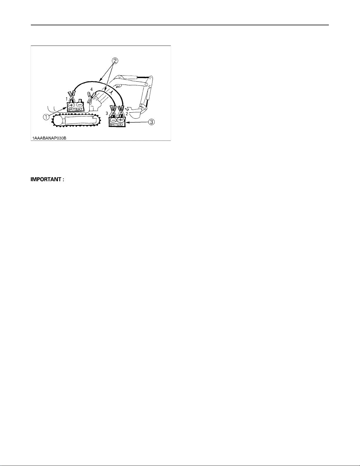
6. Connect the terminal of the red jumper cable with the
plus (+) terminal of the low battery and connect the
other end of the cable to the plus (+) terminal of the
auxiliary battery.
7. Connect the black negative cable to the minus (-)
terminal of the auxiliary battery.
8. Connect the other end of the black cable (coming from
the auxiliary battery) to the excavator frame as far
away as possible from the low battery.
9. Start the engine of the helping machine and let it run
for a while. Start the excavator with the low battery.
10.Disconnect the jumper cables in the reverse sequence
(Steps 8, 7, 6).
(1) Stop button (2) Starter key
Page 42
OPERATION OF THE ENGINE20
11.Replace the vent caps.
(1) Low battery
(2) Jumper cables
(3) Auxiliary battery
A This excavator has a negative (-) ground 12 Volt
starting system.
A Use only the same voltage when using an auxiliary
battery.
A Using a higher voltage will cause serious damage to
the electrical system. When using an auxiliary battery,
only the compatible (same) voltage is permissible.
Page 43
EXCAVATOR OPERATION
RUNNING-IN OF THE NEW EXCAVATOR
The operation and care of the new excavator influences
its life span. Your new excavator has been carefully
checked and tested before leaving the factory. In spite of
this, all movable components must run-in during the first
50 work hours. Do not work with full rpm's and full loads
during this period. It is most important to run-in your
excavator properly in order to achieve its full performance
and longevity. During the running-in, the following points
should be adhered to in all cases.
BDo not Work with Full Engine Rpm's or
Full Loads during the First 50 Working
Hours
A Let the engine warm up sufficiently in the cold season.
A Do not let the engine rev-up more than necessary.
STARTING
1. Adjusting the Operator's Position.
BOperator's Seat
To avoid personal injury or death:
A Make sure that the seat is completely secured
after each adjustment.
A Do not allow any person other than the driver to
ride on the excavator.
21EXCAVATOR OPERATION
BOil Change in the Run-in Stage
The lubrication oil plays a specific and important role
during the run-in phase of the excavator. The numerous
movable parts are not yet run-in, so many fine metal
particles are generated and cause damage and shorten
the life of many components. Pay attention to the oilchange intervals and complete them sooner than later.
See "REGULAR CHECKS AND MAINTENANCE WORK"
section for more details on the oil-change intervals.
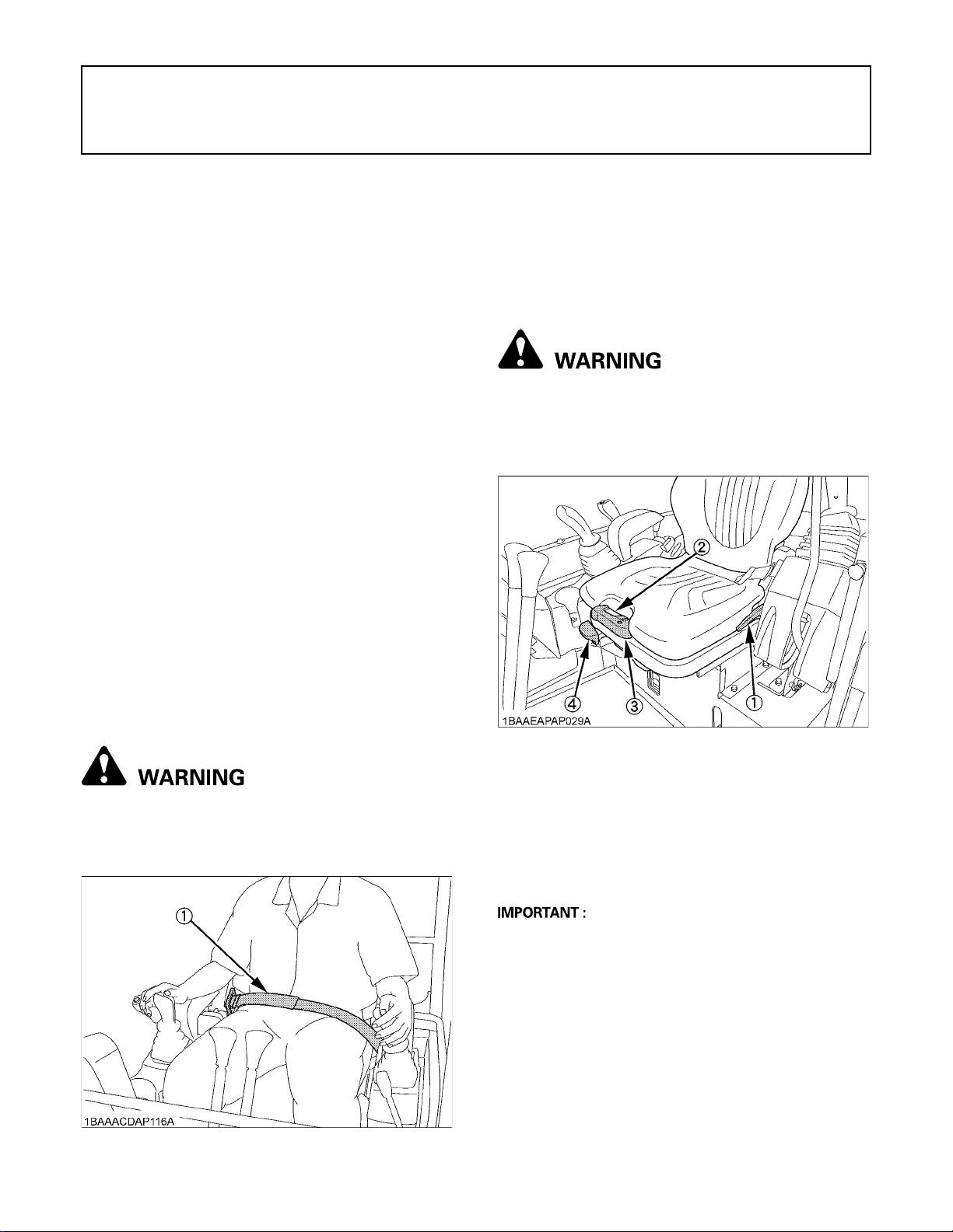
BSeat Belt
To avoid personal injury or death:
A Always use the seat belt with a ROPS/OPG (Top
Guard Level I) protection structure. Adjust the
seat to the optimal position and buckle up.
(1) Backrest adjustment lever
(2) Weight indicator
(3) Spring adjustment lever
(4) Horizontal seat adjustment lever
C Horizontal seat adjustment (seat stand-off)
Pull the horizontal seat adjustment lever up and move the
seat to the desired position by moving it forward or back,
then release the lever.
A Check that the seat is locked into place.
C Spring adjustment (driver's weight)
1. The seat can be set to the weight of the driver with the
lever. The weight indicator is provided as an
adjustment aid.
2. Pressing down the lever increases the spring tension
(suitable for heavier operators), pulling the lever
upward reduces spring tension (for lighter operators).
3. Adjust the seat so that a comfortable cushioning is
achieved.
(1) Seat belt
Page 44
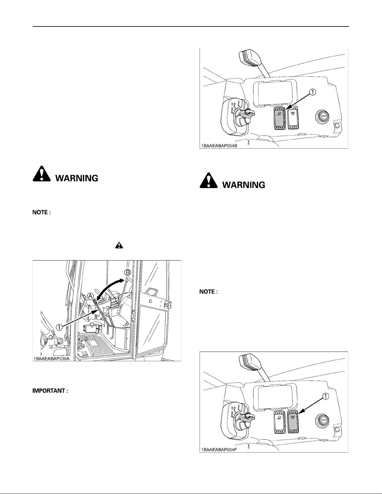
EXCAVATOR OPERATION22
C Backrest adjustment
Take the load off the backrest and pull up the backrest
adjustment lever. Set the backrest to the desired sitting
position and release the lever. The backrest should be
adjusted so that the operator can safely operate the
control levers with the back resting completely on the
backrest.
2. After starting the engine, bring the
pilot control lock lever into the
"UNLOCK" position to use drive lever
or control lever for front attachments.
BPilot Control Lock Lever
To avoid personal injury or death:
A To avoid injuries, check safety aspects all
around the excavator.
A If the pilot control lock lever is pulled down, the engine
will fail to start.
If you try to start the engine with the key with the pilot
control lock lever down, the " " lamp (yellow) starts
flashing.
(1) Working light switch
C Night operation
To avoid personal injury or death:
A When the working light alone do not provide
sufficient visibility, prepare additional
stationary artificial lighting and observe safety
rules for night work.
BTravel Buzzer
When you handle the drive levers, the buzzer sounds at
the same time or before the excavator starts to run.
BBeacon Light Switch
A The rotary beacon (accessory) is switched on with this
button.
The excavator is equipped only with the switch (including
the coupler for connecting in a rear left speaker).
Beacon is not standard equipment, therefore please
install when required.
(1) Pilot control lock lever (A) "UNLOCK"
(B) "LOCKED"
A Always pull pilot control lock lever up to "LOCKED"
position (B) when you stop the engine or leave the
operating structure.
BWorking Light Switch
When the starter switch is in position "RUN", the light(s)
will be switched on by pressing the switch.
(1) Beacon light switch
Page 45
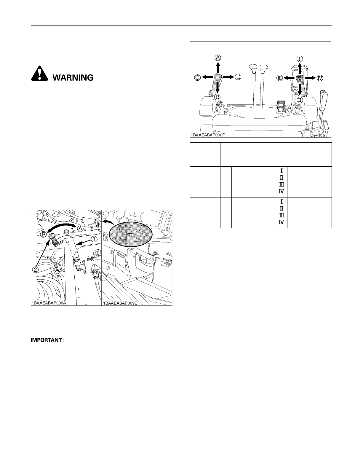
TWO PATTERN SELECTION SYSTEM (TPSS)
To avoid personal injury or death:
A Study control lever pattern A and pattern B.
Then choose the one which is most familiar.
A Position the pattern selector lever (located on
the right side of operator's seat) in either the
backward position (Pattern A) or the forward
position (Pattern B).
A Engage the lever lock to prevent accidental
pattern change.
A Familiarize yourself with the pattern selected
by operating slowly.
BPattern Change
Moving the pattern selector lever backward until the red
knob is locked in position, will activate pattern A.
Moving the pattern selector lever forward until the red
knob is locked in position, will activate pattern B.
Lever
Position
Pattern A
Pattern B
Attachment
Control Lever
(Left)
A
Boom down
B
Boom up
C
Swing left
D
Swing right
A
Arm out (up)
B
Arm in (crowd)
C
Swing left
D
Swing right
23EXCAVATOR OPERATION
Attachment
Control Lever
(Right)
Arm out (up)
Arm in (crowd)
Bucket crowd
Bucket dump
Boom down
Boom up
Bucket crowd
Bucket dump
(1) Pattern selector lever
(Two Pattern Selection System: TPSS)
(2) Red knob
A The lever and red knob will be locked automatically
when the new pattern position is reached.
A Do not operate the excavator unless the lever and red
knob have been locked into a pattern position.
(A) "Pattern A"
(B) "Pattern B"
Page 46
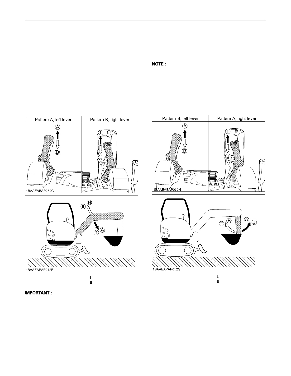
EXCAVATOR OPERATION24
OPERATION OF THE BOOM
To raise the boom, pull the attachment control lever back.
The boom is equipped with a cushion cylinder which helps
prevent excavated material in the bucket from falling out.
At low hydraulic oil temperature, (e.g. after starting the
engine in cold weather) the cushioning function will be
effected for a short period of time (approx. 3 to 5
seconds). This condition results from the viscosity of the
hydraulic oil and is not a sign of malfunction.
The cushion cylinder will operate normally as the oil
warms up.
To lower the boom, push the attachment control lever
forward.
OPERATION OF THE ARM
Pull back the attachment control lever and the arm will be
pulled in. To move the arm out, push the control lever
towards the front.
A When pulling in the arm, the movement may stop for a
short moment when the arm is in its vertical position.
This is caused by the combined load of the arm and
bucket moving the cylinder piston away from the
hydraulic flow causing a delay in the cylinder action,
until the flow catches up with cylinder piston. This is a
characteristic of the hydraulic system and is not a sign
of malfunction.
(A) ( ) Boom down
(B) ( ) Boom up
A When lowering the boom, make sure that it does not
hit the dozer and that the bucket teeth do not touch the
dozer.
(A) ( ) Arm out (up)
(B) ( ) Arm in (crowd)
Page 47
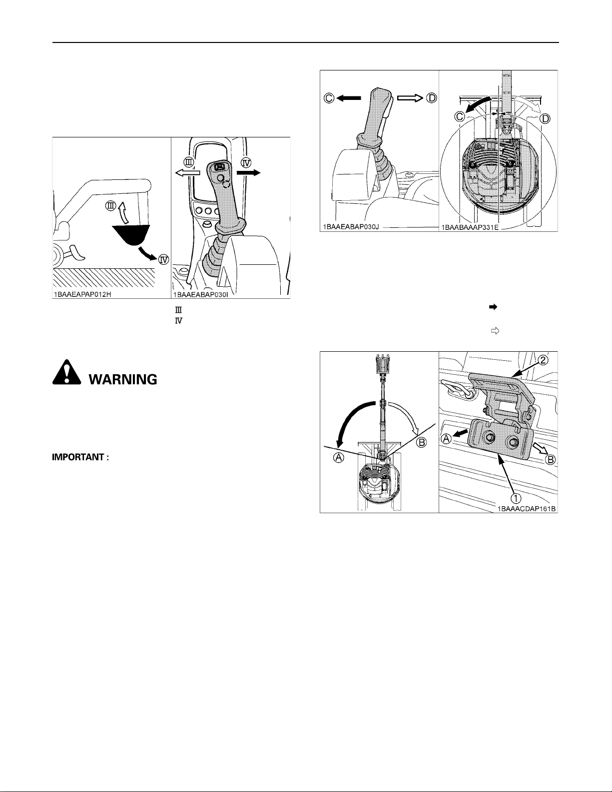
OPERATION OF THE BUCKET
To dig using the bucket, move the right attachment control
lever from the neutral position, left. Moving the control
lever right, moves the bucket outwards and dumps its
contents.
( ) Bucket crowd
() Bucket dump
SWIVEL(UNIT SWING)OPERATION
25EXCAVATOR OPERATION
(C) Swing left
(D) Swing right
BOOM SWING OPERATION
1. Flip the pedal lock up to unlock the pedal.
2. Step on the left side of the pedal ( ) to swing the
boom to the left.
3. Step on the right side of the pedal ( ) to swing the
boom to the right.
To avoid personal injury or death:
A When working in groups, always let the others
know what you are going to do before you do it.
A Keep others away from the machine working
area.
A Do not operate the left attachment control lever
abruptly from right to left (or vice versa). Because of
the low of inertia, this causes an impact load on the
swing gear and the swing motor. Additionally, the life
of the excavator will be shortened.
1. Move the control lever to the left and the upper
structure will turn to the left.
2. Move the control lever to the right and the upper
structure will turn to the right.
(1) Boom swing pedal
(2) Pedal lock
(A) Swing left
(B) Swing right
Page 48
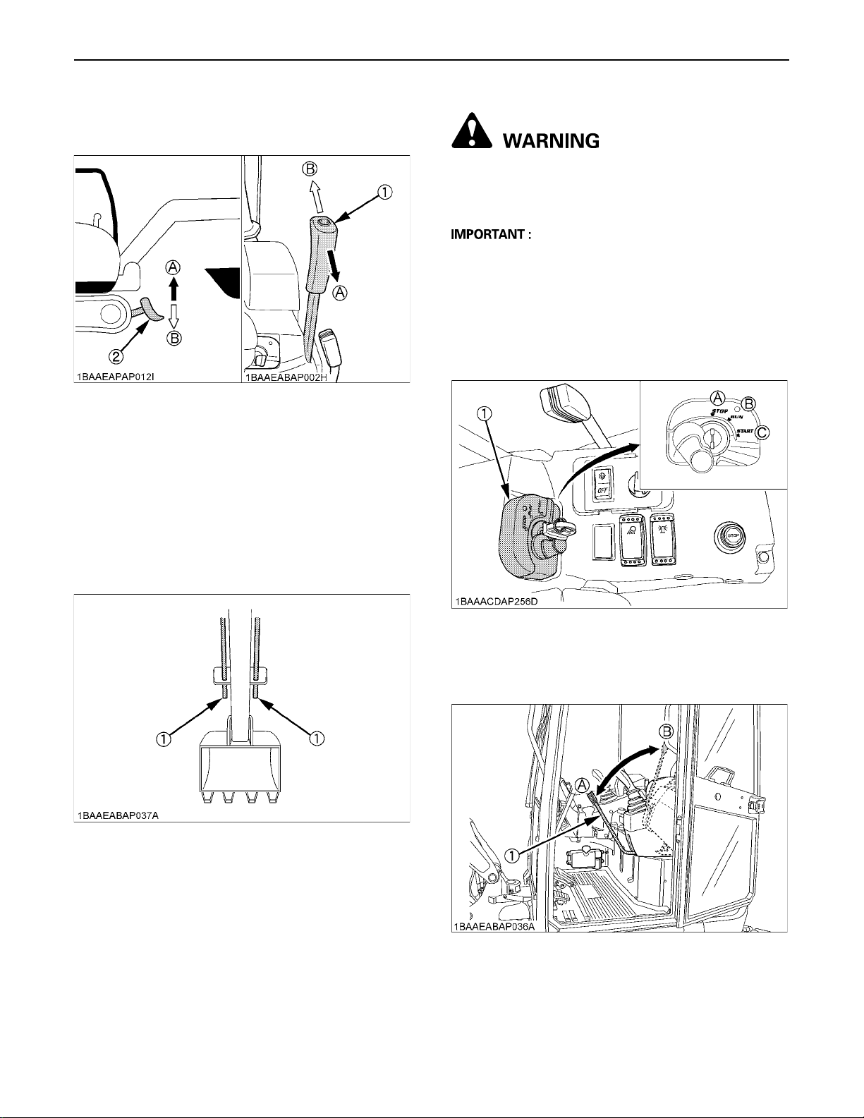
EXCAVATOR OPERATION26
OPERATION OF THE DOZER
1. To raise the dozer, pull back the control lever. Pushing
the control lever forwards lowers the dozer.
(1) Dozer control lever
(2) Dozer
2. While undertaking earth moving work, control both
drive levers with left hand and the dozer control lever
with right hand.
(A) "Raise"
(B) "Lower"
C Operating auxiliary port 1
To avoid personal injury or death:
A Check not only indicator for auxiliary port but
also function before you start to operate the
machine.
A The proportional control enables you to smoothly
control the implement speed. Example: If you press
the rocker switch halfway to the left, the implement
moves at approximately half speed.
1. Turn the starter key to the "RUN" position.
Let the engine warm up after start-up for approx. 10
minutes under no load conditions.
AUX PORT OPERATION
The excavator is equipped with a hydraulic auxiliary ports.
The auxiliary port function is controlled with the rocker
switch for auxiliary port.
(1) Auxiliary port
(1) Starter switch (A) "STOP"
(B) "RUN"
(C) "START"
2. Lower the pilot control lock lever (UNLOCK).
(1) Pilot control lock lever (A) "UNLOCK"
(B) "LOCKED"
Page 49
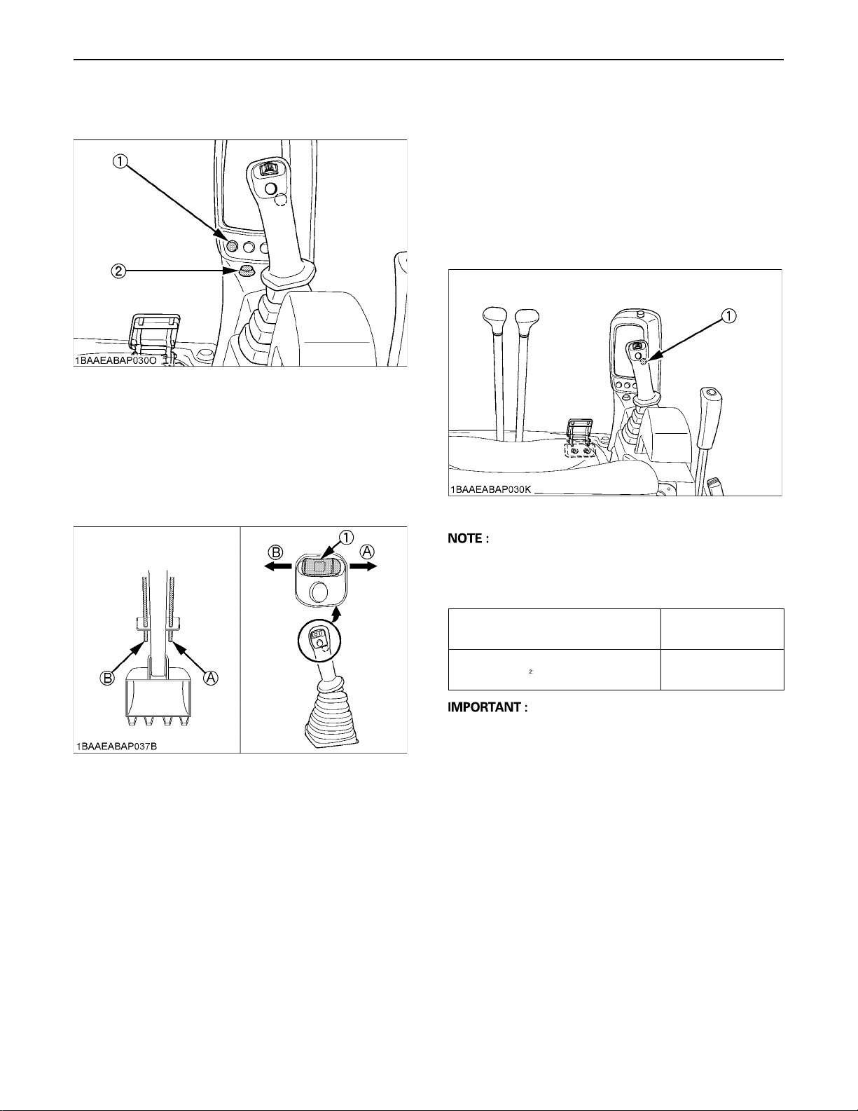
3. Push the enable switch for auxiliary port (switch 1).
Check the indicator for auxiliary port lights up.
(1) Enable switch for auxiliary port (switch 1)
(2) Indicator for auxiliary port
4. Press rocker switch for auxiliary port in the direction
right (A), then the oil flows to the right connector (A) of
the arm.
Press rocker switch for auxiliary port in the direction
left (B), then the oil flows to the left connector (B) of the
arm.
27EXCAVATOR OPERATION
BOne-way Hold Switch
Operating the one way hold switch results in a continuous
oil flow to the auxiliary port connector to the left of the arm.
When you operate it again, the oil flow discontinues. Thus,
you can operate, for example, an attachment without
having to continuously hold down the button.
Before operating the one way hold switch press the rocker
switch for auxiliary port to left and keep the position.
(1) One way hold switch
(1) Rocker switch for auxiliary port (A) Port A
(B) Port B
A One way hold operation needs an 1-way circuit to
reduce the back pressure (see page 33).
Max. Flow Volume
Theoretical L/min. (US gal/min.)
Max. Pressure
MPa (kgf/cm ) [psi]
48.0 (12.8)
21.6 (220) [3133]
A When the AUX port is not used for a long period, dirt
particles can settle in the lower part of the AUX port
lines.
When the plugs on the AUX port lines are removed to
connect attachments, drain approx. 100 cc (3.4 oz) of
oil per side.
For breaker choices, contact your dealer.
Page 50
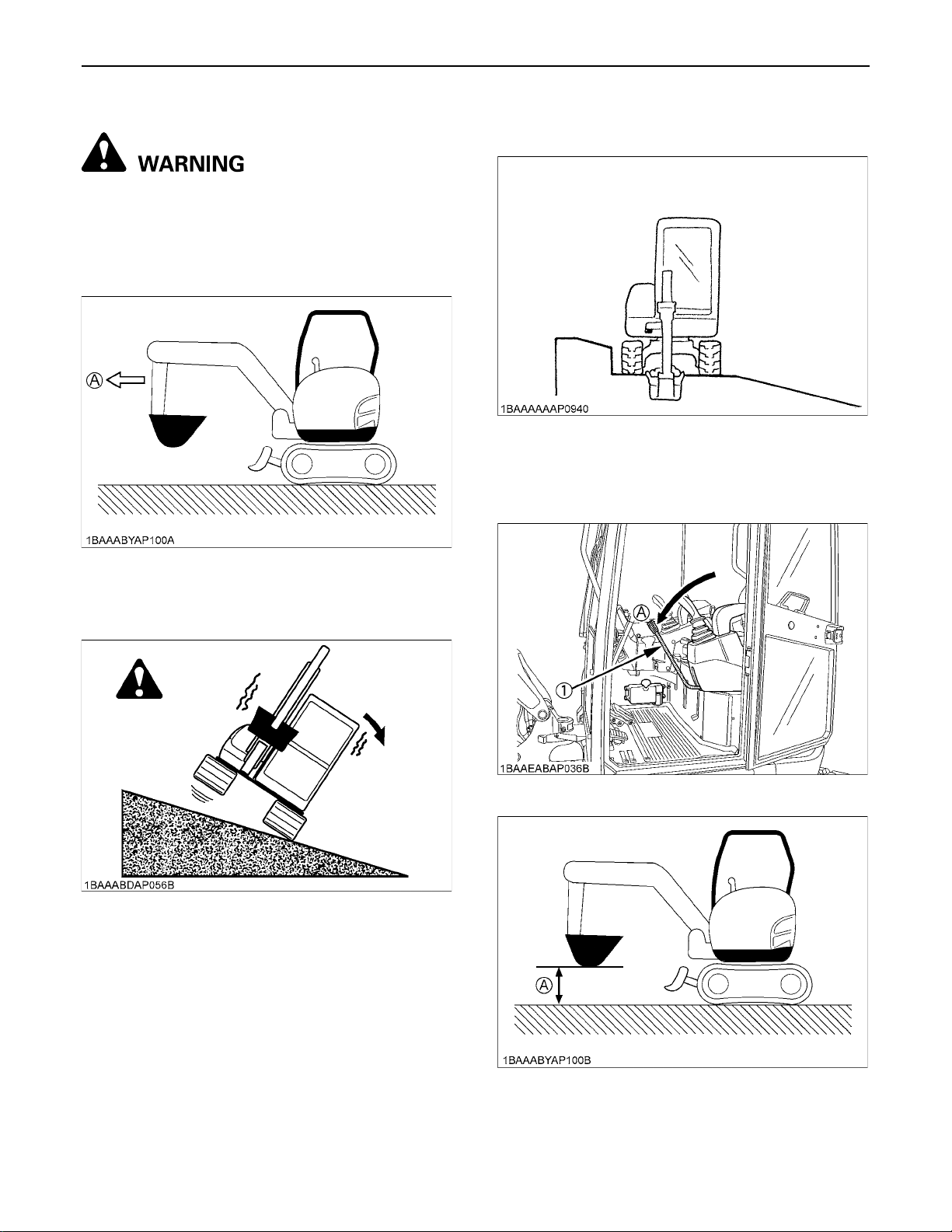
EXCAVATOR OPERATION28
DRIVING
To avoid personal injury or death:
A Before starting the engine, make sure that no
one is near the excavator.
A Before operating the excavator, check the track
direction. (Idler and dozer to the front of the
excavator).
A Recommended technique for working on a
slope.
1. Adjust the engine speed from idling to an intermediate
speed.
2. Unlock the pilot control lock lever.
3. Raise the dozer and hold the bucket about 20 to 40 cm
(8 to 16 in.) over the ground.
(A) "Front"
A Use extra caution when traveling across a
slope or working sideways on a slope.
(1) Pilot control lock lever (A) "UNLOCK"
(A) 20 to 40 cm (8 to 16 in.)
Page 51
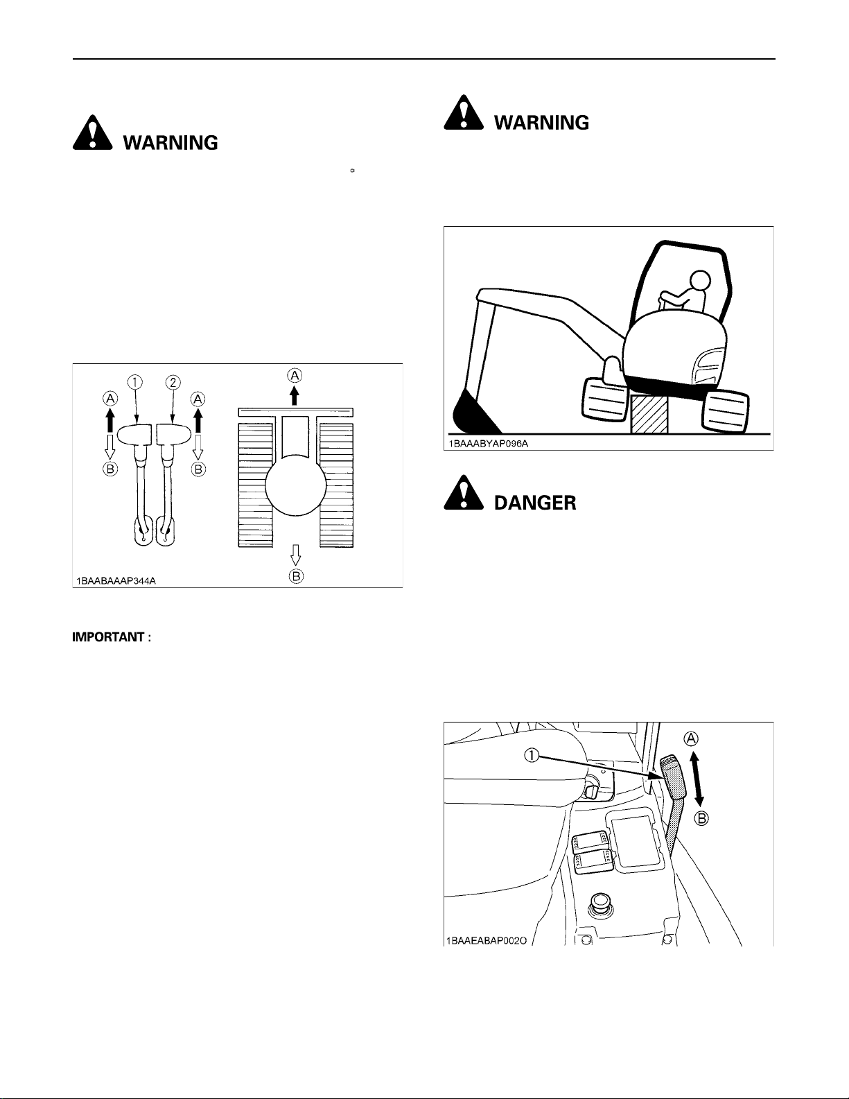
BDrive Levers (Right, Left)
To avoid personal injury or death:
A If the swing frame has been turned 180 , i.e. the
dozer blade is, seen from the operator,
"behind", then the travel direction is opposite
to the drive direction of the levers (when
activating the drive lever forwards, the
excavator, seen from the operator, will move
backwards).
Pushing the drive lever forward, moves the excavator
forward, and vice-versa. The front of the excavator is the
direction where the dozer is present.
29EXCAVATOR OPERATION
To avoid personal injury or death:
A When lifting the machine with an attachment,
place a safety block or safety post to prevent
the machine from turning over. Keep the pilot
control lock lever in the "LOCKED" position.
(1) Drive lever (left)
(2) Drive lever (right)
(A) "Forward"
(B) "Backward"
A If the tracks are clogged with sand or gravel while
working on soft ground, lift up one track with the help
of the boom, arm and bucket and let the track rotate to
shake off the sand and gravel.
To avoid serious injury or death:
A Do not work under the machine in this
condition.
BThrottle Lever
At the operator's seat,
1. Move the throttle lever to the "FAST" position, and the
engine speed increases.
2. To stop the engine, push the throttle lever fully to the
"SLOW" position and turn the starter switch to the
"STOP" position.
(1) Throttle lever (A) "FAST"
(B) "SLOW"
Page 52
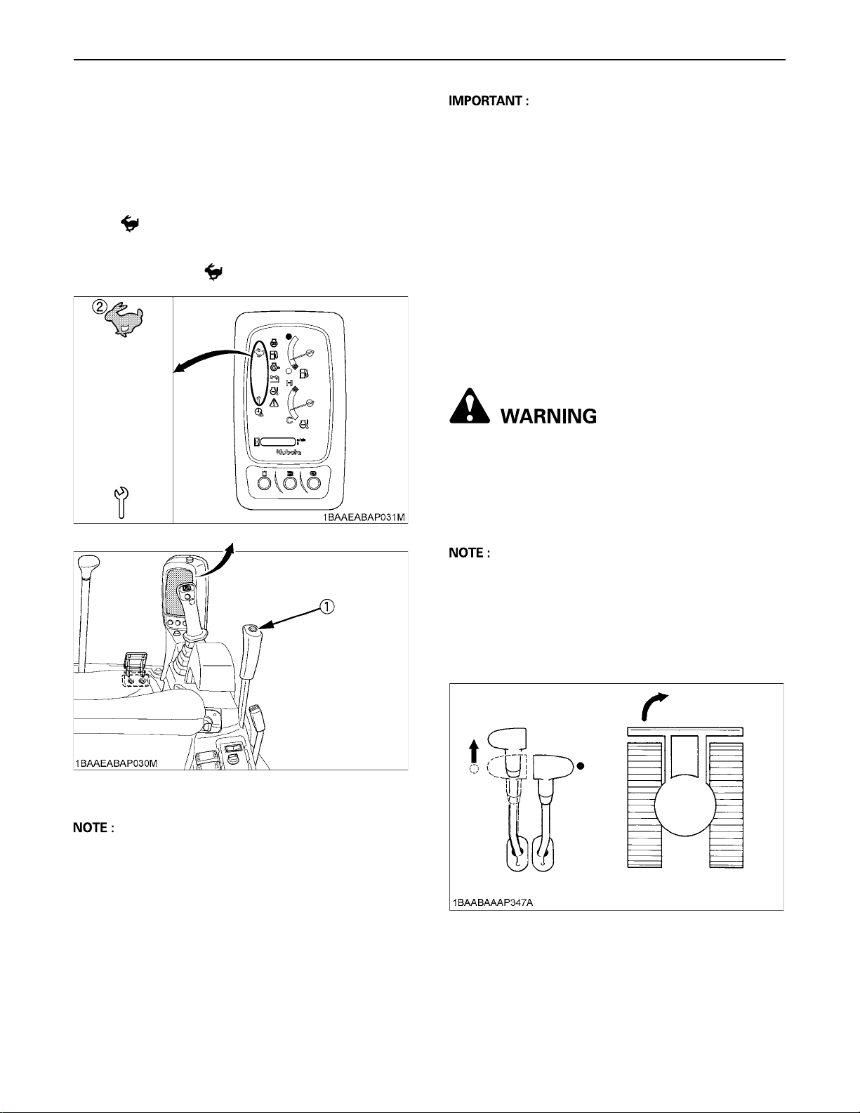
EXCAVATOR OPERATION30
BTravel Speed Switch
Travel speed will increase when this switch is pushed
down.
Switching the dual travel speed:
1. Press the travel speed switch. The buzzer beeps and
the travel speed changes from first speed to second.
The symbol lights up.
2. Press the travel speed switch again, and the buzzer
beeps and the travel speed changes from second
speed to first. The symbol light goes out.
A Do not activate the travel speed switch when there is
increased drive resistance (e.g. driving on inclines or
on uneven grounds).
A If the tracks are clogged with sand or gravel while
working on soft ground, lift up one track with the help
of the boom, arm and bucket and let the track rotate to
remove the sand and gravel.
A The U27-4 HI model is equipped with an automatic
switching mechanism controlled by the torque, which
automatically shifts the drive engines from travel
speed into the more comfortable low speed when
driving at lower speeds with a heavy load or when
turning, for example. However, for safety reasons,
shifting back up into travel speed must always be done
manually using the travel speed switch.
TURNS
To avoid personal injury or death:
A Do not change direction on steep slopes, or the
excavator could tip over.
A Before changing direction, beware of people in
the work area.
(1) Travel speed switch
(2) Speed indicator lamp
A When activating the travel speed switch, it must be
pushed down completely.
A Each time the travel speed switch is pressed, the
travel speed is switched between first and second.
BPivot Turn
A Movement as illustrated shows the turning directions
with the dozer blade in the front.
C Change of Direction while Stationary
1. Push the left drive lever forward;
the excavator will turn in the direction of the arrow of
the illustration below.
2. Pull the left drive lever backward;
the excavator will turn in the direction of the arrow of
the illustration below.
Page 53
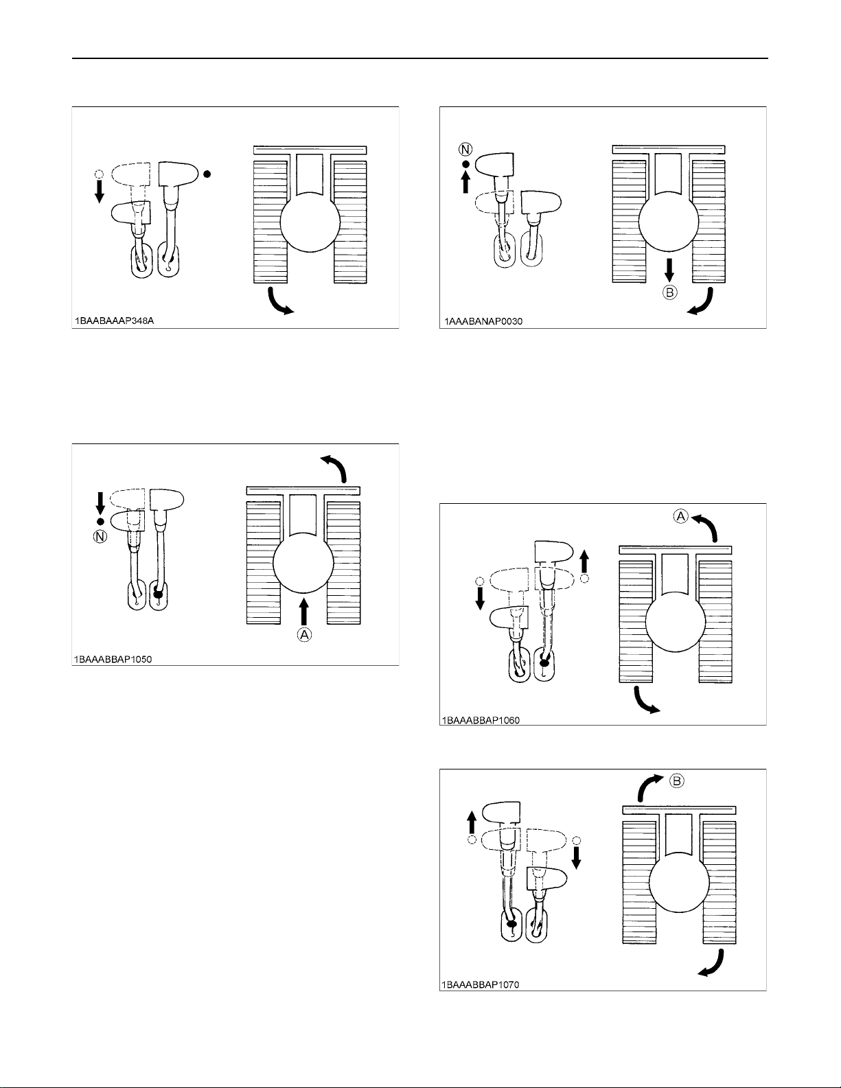
C Change of Direction while Travelling
1. While travelling forwards, bring the left drive lever in
the neutral position;
the excavator will turn in the direction of the arrow of
the illustration below.
31EXCAVATOR OPERATION
(B) "Travelling backward"
(N) "Neutral position"
BSpin Turn
When both drive levers are activated in the opposite
directions, both track will rotate with the same speed but
in opposite directions. The center of rotation is the center
of the excavator.
(A) "Travelling forward"
(N) "Neutral position"
2. While travelling backwards, bring the left drive lever in
the neutral position;
the excavator will turn in the direction of the arrow of
the illustration below.
(A) "Left spin turn"
(B) "Right spin turn"
Page 54
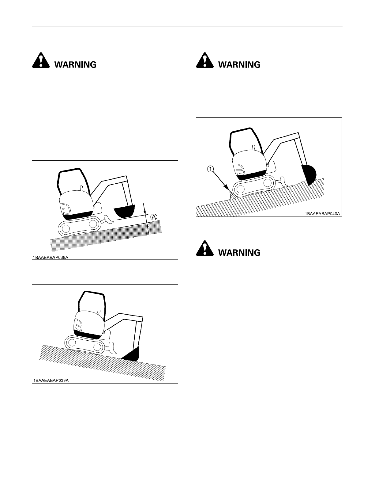
EXCAVATOR OPERATION32
UP AND DOWNHILL TRAVELLING
To avoid personal injury or death:
A When travelling up or down a slope, use extra
caution and follow the instructions below.
While travelling uphill, keep the lower edge of the bucket
approx. 20 to 40 cm (8 to 16 in.) above the ground.
Although the KUBOTA excavator will not slip easily
because of the crawlers, it is safer to let the bucket slide
over the ground while travelling downhill.
Always choose slow speed for uphill and downhill
travelling.
[UPHILL TRAVELLING]
PARKING ON A SLOPE
To avoid personal injury or death:
A When the excavator is parked or left
unattended on a slope, be sure to put the tip of
the bucket into the ground and place all control
levers in neutral position, then brace the tracks
with chocks.
(1) Chock
[DOWNHILL TRAVELLING]
(A) 20 to 40 cm (8 to 16 in.)
PARKING
To avoid personal injury or death:
A Do not keep the bucket or dozer in an elevated
position, as a person could accidentally touch
the levers and cause serious accidents.
1. Park the machine on hard flat ground. Stand the arm
vertically and lower the bucket to the ground.
2. Turn the throttle potentiometer fully to low speed and
idle the engine for about 5 minutes to cool it off
gradually.
3. Turn the starter switch to "STOP", stop the engine,
then remove the key.
4. Pull the pilot control lock lever up to the "LOCKED"
position.
5. When leaving the machine, close all covers and lock.
Page 55
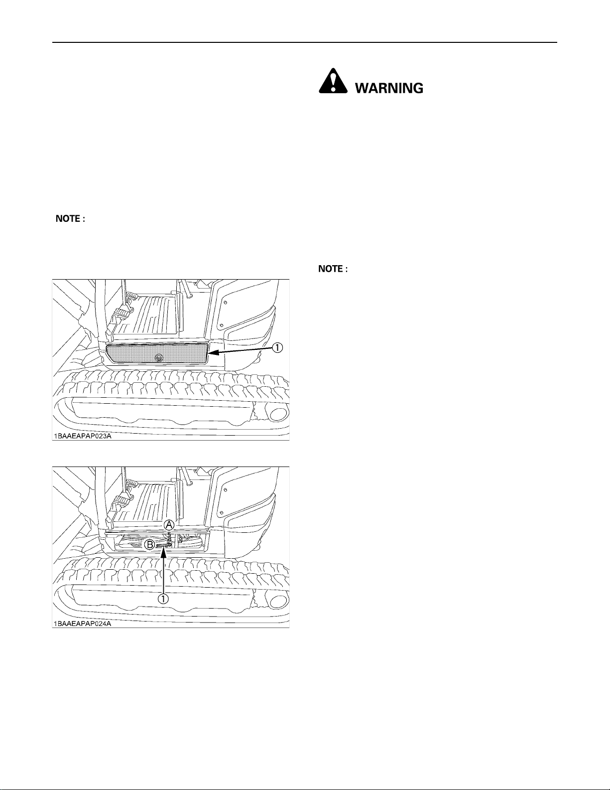
1-way or 2-way CIRCUIT SELECTION VALVE OPERATION
A selection valve which selects 1-way or 2-way circuit of
AUX port has been installed on the hydraulic tank.
1. When equipment which needs a 1-way circuit will be
used, position the arrow, by using the selector lever,
on the axis of the selection valve to the 1-way circuit
position, to reduce the back pressure.
2. When equipment which needs a 2-way circuit will be
used, position the arrow on the axis of the selection
valve to the 2-way circuit position.
A 1-way circuit.....
A 2-way circuit.....
HAMMER etc.
THUMB, TILT BUCKET,
AUGER, GRAPPLE etc.
33EXCAVATOR OPERATION
To avoid personal injury or death:
A Stop the engine before removing/changing the
equipment.
A Release pressure in the hydraulic system
before removing/changing the equipment. (See
"HOW TO RELEASE PRESSURE TRAPPED IN
THE HYDRAULIC SYSTEM".)
A Position the selection valve to the correct
position (either 1-way or 2-way circuit
selection) before mounting the equipment.
A Always select the correct valve position before
mounting the equipment (1-way or 2-way
circuit selection) to avoid sudden movement of
the equipment.
A Leaving the selection valve to 1-way circuit selection
and attaching 2-way circuit equipment may cause the
equipment to move (drop) suddenly due to its own
weight, as the tank line remains open, even with the
engine off.
(1) Swivel frame cover
(1) Selector lever (A) "1 way"
(B) "2 way"
Page 56
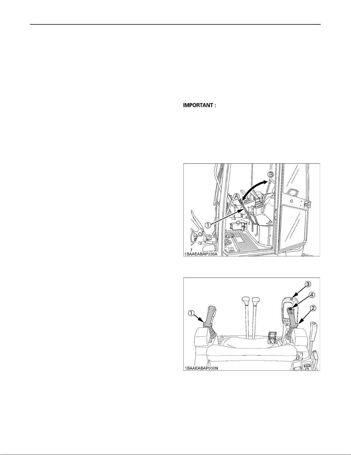
EXCAVATOR OPERATION34
IMPORTANT INFORMATION ON EXCAVATOR OPERATION
A Do not try to crush concrete or boulders using side
swings with the bucket. Also avoid using side sweeps
of the bucket to move earth piles.
A Under all circumstances avoid the following
operations:
A Excavation using the gravitational impact of the
machine.
A Compacting of gravel or soil using the dropping
action of the bucket.
A Excavation using the traveling power of the
machine.
A Do not try to drop or shake off soil adhering to the
bucket in the manner given in the points below. This
can cause damage to the machine.
Adhering soil can be shaken off when the bucket is
being emptied by moving the bucket out to the
maximum stroke of the cylinder. Should this not
suffice, swing out the arm as far as possible and
operate the bucket back and forth.
A Do not hit the dozer with the boom cylinder!
Make sure that the boom cylinder does not hit the
dozer when doing deep excavation. If necessary
swing around so that the dozer is in the back of the
machine.
A Pay attention when pulling in the bucket!
When pulling in the bucket (for driving or
transportation) avoid hitting the dozer.
A Avoid collisions!
When moving the excavator, pay attention that the
dozer does not collide with obstructions such as
boulders, etc.
Such collisions shorten the life of the dozer and the
cylinder substantially.
A Support the machine correctly!
When stabilizing the machine with the dozer, lower the
dozer to engage the full width on the ground.
A If the water or mud level reaches higher than the top of
the tracks, the swivel bearing, swivel motor gear and
ring gear may be exposed to mud, water and other
foreign objects.
The excavator must be properly pressure washed
after each use.
A Thoroughly clean the area around the swivel
bearing, swivel motor gear and ring gear to remove
foreign objects.
A Inspect the swivel motor oil sump (if equipped) for
water contamination. If water is present, refer to
operator's manual for lubricant replacement
procedure.
A Refer to operator's manual for proper swivel
bearing, swivel motor gear and ring gear
lubrication procedures.
A Reinstall any protective covering if removed
earlier.
HOW TO RELEASE PRESSURE TRAPPED IN THE HYDRAULIC SYSTEM
1. Lower the attachments and the dozer blade to the
ground.
2. Turn the key to "STOP" position and shut off the
engine.
3. Wait until the engine has come to a standstill.
4. Turn the key to "RUN" position.
A Do not start the engine.
5. Set the pilot control lock lever to "UNLOCK" position.
6. Move control levers for front attachment (left and right)
several times to limit stop in all directions.
7. Set the potentiometer to the maximum flow rate.
Then the hydraulic system has been depressurised.
(1) Pilot control lock lever (A) "UNLOCK"
(B) "LOCKED"
(1) Control lever for front attachment (Left)
(2) Control lever for front attachment (Right)
(3) Potentiometer for auxiliary port
(4) Rocker switch for auxiliary port
Page 57
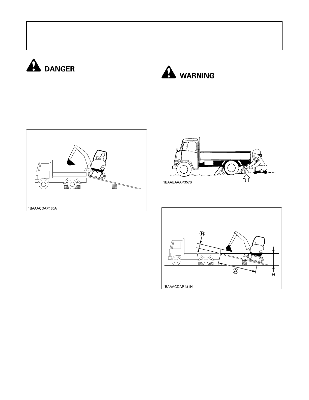
35TRANSPORTING THE EXCAVATOR ON A TRUCK
TRANSPORTING THE EXCAVATOR ON A TRUCK
B Transporting on a Truck
To avoid serious injury or death:
A No directional changes should be made when
the excavator is on the ramp. Should a change
of direction be necessary, drive off the ramp
completely and make the turn.
A When driving forwards or backwards onto the
truck, or when swinging the upper body, make
sure that neither the cabin or the gates of the
truck will be damaged.
To avoid personal injury or death:
A After loading the machine on the truck, lower
the bucket and dozer onto the truck bed.
Prepare a platform to load or unload the excavator. Take
following steps when using ramps.
1. Apply the parking brakes of the truck, and block the
drive wheels from both sides.
A When the excavator reaches the point between
the ramps and the truck bed, halt and then
move very slowly until the excavator reaches
the horizontal position.
A Move the excavator onto the truck only with the
arm completely pulled in. Otherwise the truck
cabin could be damaged when swinging
around the upper body.
A Do not jack up the machine using its boom to
load or unload the excavator from the truck.
Dangerous situation could arise.
2. Use mounting brackets to secure the ramp properly.
Connect the ramps directly to the truck bed.
(A) 4 x H or more
(B) 20 to 40 cm (8 to 16 in.)
3. For additional safety, use blocks or supports under the
ramps and the truck bed.
4. Align the ramps and the tracks and then drive the
excavator slowly up the ramps with the dozer in the
front. After ensuring that the tracks are completely on
the truck bed, swivel the upper body around to the
back of the truck.
Page 58
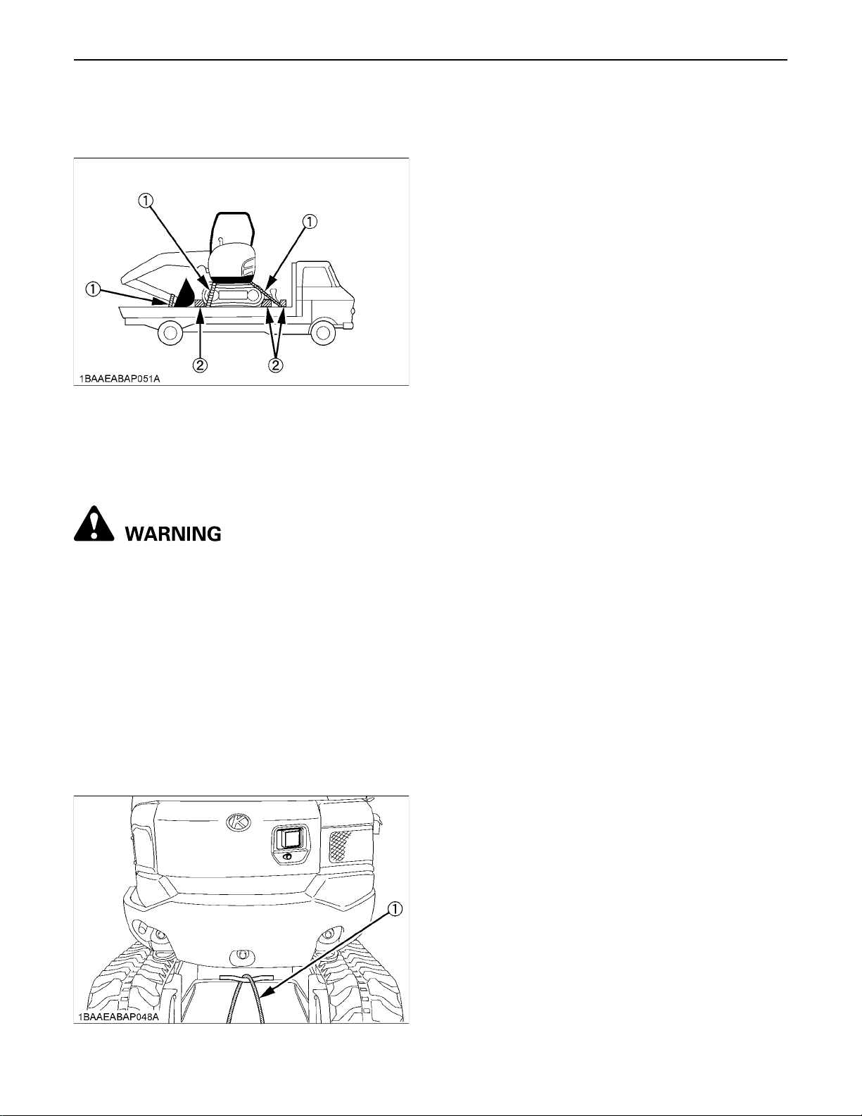
TRANSPORTING THE EXCAVATOR ON A TRUCK36
5. Block the tracks and tie down the excavator with
suitable chains and approved method (check
appropriate state regulation).
(1) Chain
(2) Block
6. Before unloading, raise the dozer and bucket from the
truck bed.
B Towing the machine
To avoid personal injury or death:
A When towing the excavator or pulling a load
must be less than the strength of the towing
line attached to excavator. Not to be used for
tie-down or lifting the machine.
A Towing is only allowed over a short distance
and at walking speed.
1. Attach the tow bar or towing rope to the hook on the
excavator and to the pulling vehicle. The tow bar
should be mounted at a right angle to the vehicles.
2. The operator must be seated during the recovery
procedure.
3. Drive slowly with the tractive vehicle to avoid abrupt
loads.
(1) Tow line
Page 59
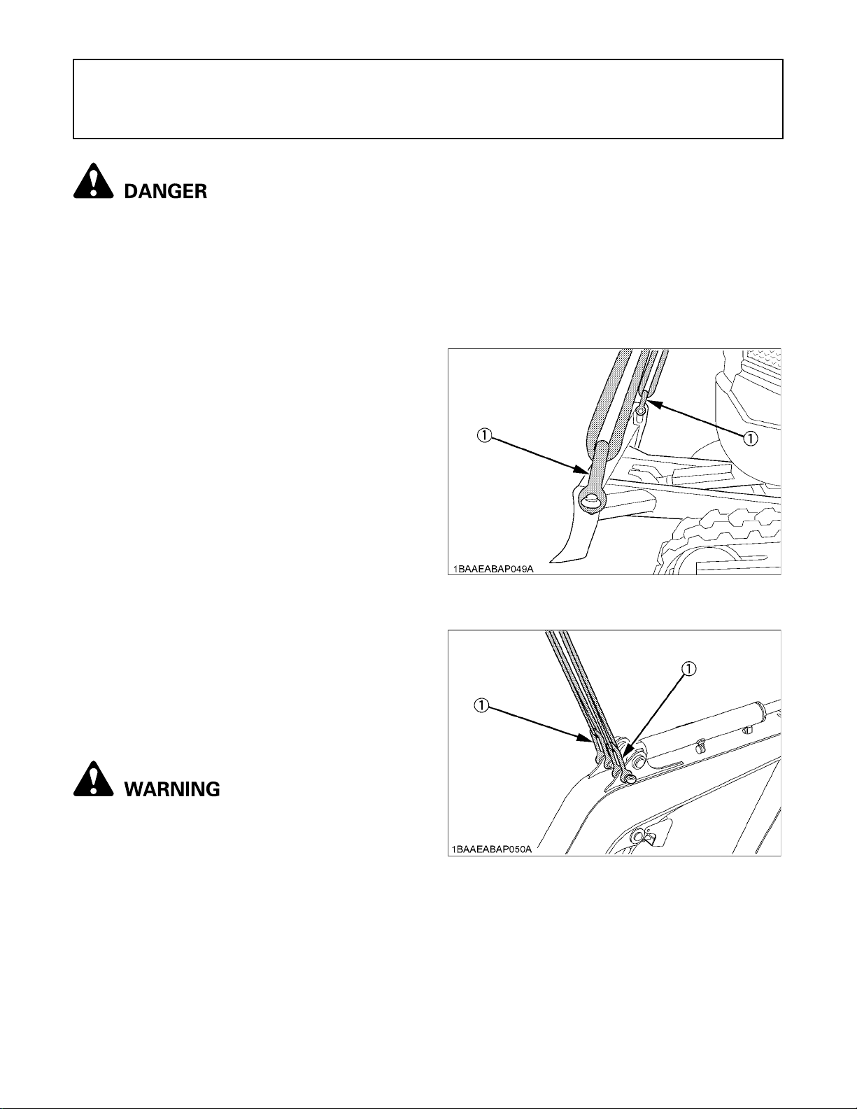
LIFTING OF THE EXCAVATOR
C General guidelines for lifting
1. Lifting position. (see illustration)
To avoid serious injury or death:
A The correct instructions for safe handling are
described here. Read these instructions
carefully before moving the machine. Make
sure that the operating personnel read the
operator's manual carefully.
B Basics when Lifting with Cables or Straps
1. The lifting and crane operation is to be undertaken
according to the guidelines described.
2. The equipment used for lifting mentioned in these
instructions are only given as reference, the standards
concerning strength, control and other details are
based on the respective applicable guidelines.
(1) Pull in the boom towards rear.
(2) Pull in the arm completely.
(3) Pull in the bucket completely.
(4) Adjust the swing angle to the center. (to bring the
boom in a position parallel to the machine frame)
(5) Swing frame so that dozer blade is to the rear and
frame is parallel with tracks.
(6) Raise the dozer blade fully.
[Blade ends]
37LIFTING OF THE EXCAVATOR
B Safety Aspects when Lifting with Cables
or Straps
Abide by following steps when lifting:
1. Do not lift loads that exceed the maximum load
capacity of the crane.
2. Choose correct equipment suitable to the weight, size
and form of the load.
3. First assess the center of gravity of the load, position
the hook directly over the load and lift the load so that
the center of gravity of the load is as low as possible.
4. The steel cables or straps must be fixed in the middle
of the hook.
5. The load must be lifted vertically from the ground.
6. Do not enter the working area under suspended loads
and do not move the load over people. The load must
only be moved in an area where the balance can be
easily maintained.
B Lifting Procedure for the Excavator
To avoid personal injury or death.
A Do not use the hooks on the roof of canopy or
cabin for lifting the excavator.
A The excavator may only be lifted at the points
provided. Do not attach the lifting gear to any
other eyes or areas as this can lead to
substantial damage.
(1) Shackle
[Boom top]
(1) Shackle
Page 60
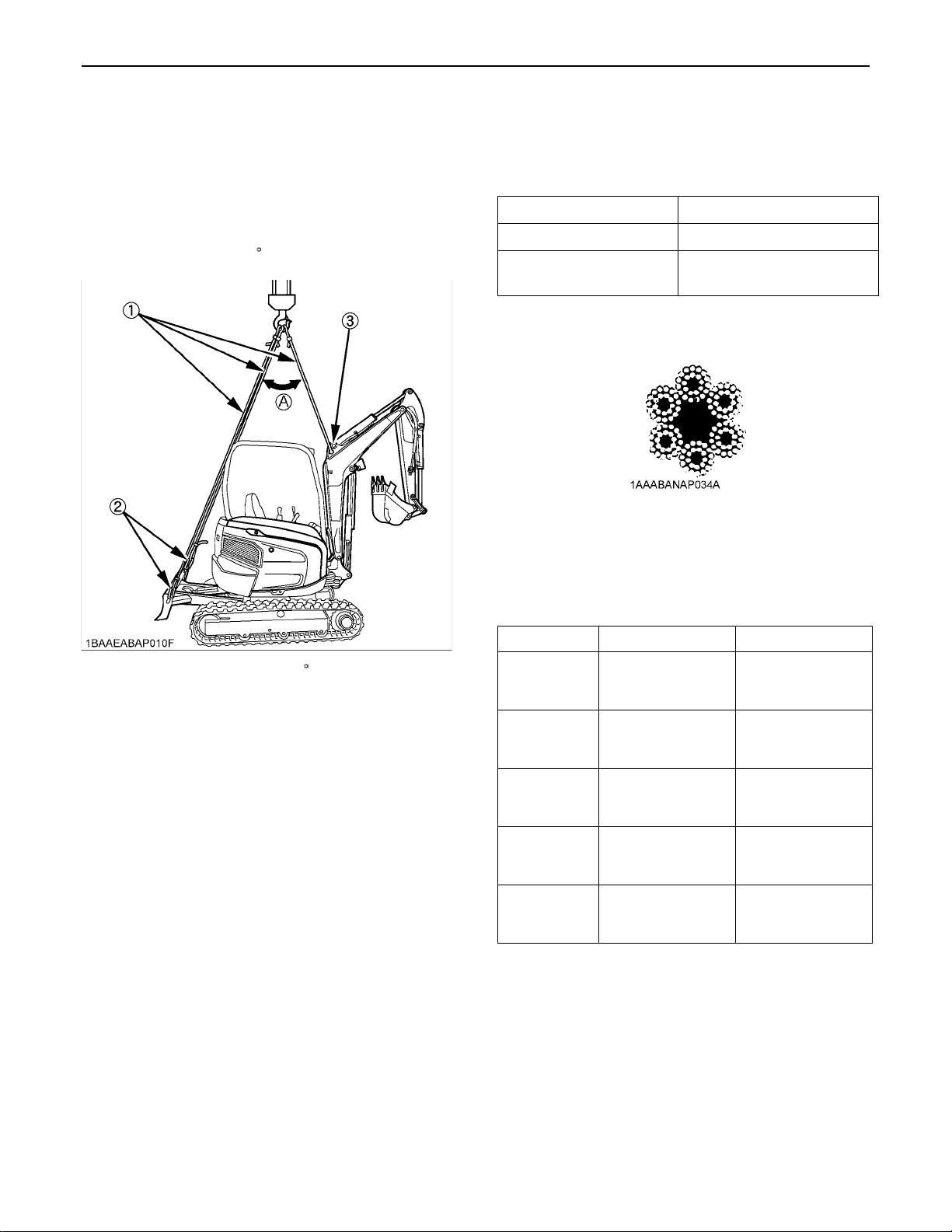
LIFTING OF THE EXCAVATOR38
2. Attaching the steel cables or straps.
(1) Always hook the excavator at three points. (one
on the boom and right and left of the dozer)
(2) Always use a shackle on each lifting hole when
attaching the cables or straps.
(3) Use protective material at all places where the
cables or straps contact the machine.
(4) Keep the angle between the front and rear cables
or straps within. 30 (0.52 rad.).
(1) Steel cable
(2) Shackle
(3) Protective material
(A) 30 (0.52 rad.) or less
3. Tackle
The weights of the excavators and the recommended
tackle for lifting these loads are mentioned in the
following table. Choose components having enough
strength.
Excavator Weight* 2520 kg (5561 lb)
Load / Cable 8500 N (866.7 kgf) [1911 lbf]
Minimum Cable Diameter
(Safety factor=6)
12.5 mm (0.49 in.) or more
*Excavator Weight: With canopy, steel tracks.
Steel cable: 6X24
4. Lifting
(1) Lift slowly and safely
(2) Do not enter the excavator area when lifting.
(3) Lift the excavator horizontally. (Modify cable or
strap connections according to needs)
Maximum strength
for example: (ISO 4344: 2004) - "6X24"
Diameter zinc-plated not zinc-plated
10 mm (3/8)
12.5 mm (1/2)
14 mm (9/16)
16 mm (5/8)
18 mm (45/64)
45.8 kN
(4670 kgf)
[10296 lbf]
71.5 kN
(7290 kgf)
[16072 lbf]
89.7 kN
(9146 kgf)
[20163 lbf]
117 kN
(11930 kgf)
[26301 lbf]
148 kN
(15091 kgf)
[33270 lbf]
49.3 kN
(5027 kgf)
[11083 lbf]
77 kN
(7851 kgf)
[17308 lbf]
96.6 kN
(9850 kgf)
[21716 lbf]
126 kN
(12848 kgf)
[28325 lbf]
160 kN
(16315 kgf)
[35968 lbf]
Page 61
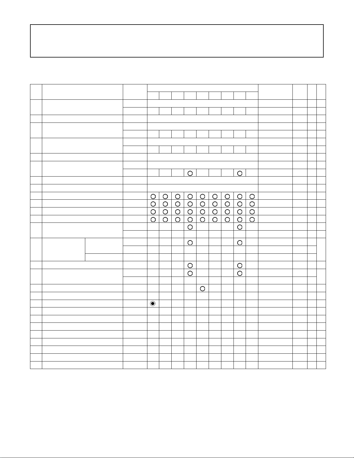
MAINTENANCE
MAINTENANCE INTERVALS
39MAINTENANCE
No. Check points Measures
1 Coolant
2 Fuel check Daily check 44
3 Engine oil
4 Hydraulic oil
5 Lubrication points - Daily check 46
6 Fan belt tension
7 Radiator and oil cooler check Daily check 47
8 Engine and electrical wiring check Daily check 48
9 Fuel tank, Fuel filter drain every 50 hrs 49
10 Water separator drain every 50 hrs 49
11 Battery condition check every 50 hrs 50
12 Greasing swing bearing teeth - every 50 hrs 51
13 Radiator hoses and clamps
14 Air filter element
15 Greasing swing ball bearing - every 200 hrs 53
16 Fuel line and Intake air line
17 Pivot valve - every 250 hrs 54
18 Engine oil filter replace every 500 hrs 55 *5
19 Drive unit oil change every 500 hrs 56 *5
20 Fuel filter cartridge replace every 500 hrs 56 *5 @
21 Hydraulic return filter element replace every 500 hrs 57 *5
22 Hydraulic suction filter element replace every 1000 hrs 58 *5
23 Fuel injection nozzle injection pressure check every 1500 hrs 59 *4 @
24 Front idler and track roller oil change every 2000 hrs 59 *5
25 Alternator and starter motor check every 2000 hrs 59
26 Injection pump check every 3000 hrs 60 *4 @
27 Radiator system rinse every 2 years 60
Outer element
Inner element replace every 1000 hrs 59 *2
check Daily check 43
change every 2 years 60
check Daily check 44
change every 500 hrs 54 *5
check Daily check 45
change every 1000 hrs 58 *1
check Daily check 47
adjust every 200 hrs 51
check every 200 hrs 52
replace every 2 years 60
clean every 200 hrs 52 *2
replace every 1000 hrs 59 *2
check every 200 hrs 53
replace every 2 years 61 *3
50 100 150 200 250 300 350 400 450
Hour meter indicator
Intervals
Ref.
page
@
@
D 500 thru 1000 continued to the following table.
Page 62
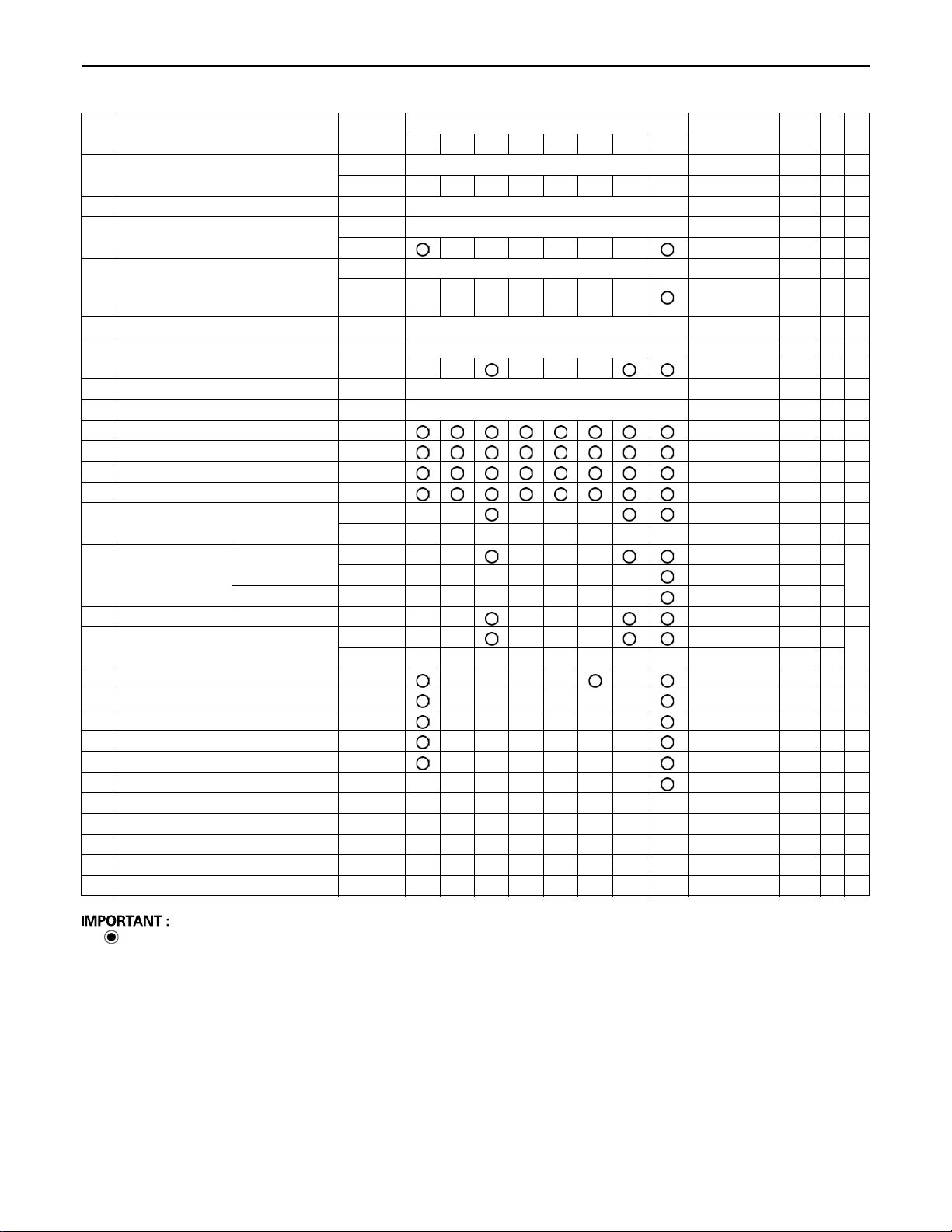
40 MAINTENANCE
No. Check points Measures
1 Coolant
2 Fuel check Daily check 44
3 Engine oil
4 Hydraulic oil
5 Lubrication points - Daily check 46
6 Fan belt tension
7 Radiator and oil cooler check Daily check 47
8 Engine and electrical wiring check Daily check 48
9 Fuel tank, Fuel filter drain every 50 hrs 49
10 Water separator drain every 50 hrs 49
11 Battery condition check every 50 hrs 50
12 Greasing swing bearing teeth - every 50 hrs 51
13 Radiator hoses and clamps
14 Air filter element
15 Greasing swing ball bearing - every 200 hrs 53
16 Fuel line and Intake air line
17 Pivot valve - every 250 hrs 54
18 Engine oil filter replace every 500 hrs 55 *5
19 Drive unit oil change every 500 hrs 56 *5
20 Fuel filter cartridge replace every 500 hrs 56 *5 @
21 Hydraulic return filter element replace every 500 hrs 57 *5
22 Hydraulic suction filter element replace every 1000 hrs 58 *5
23 Fuel injection nozzle injection pressure check every 1500 hrs 59 *4 @
24 Front idler and track roller oil change every 2000 hrs 59 *5
25 Alternator and starter motor check every 2000 hrs 59
26 Injection pump check every 3000 hrs 60 *4 @
27 Radiator system rinse every 2 years 60
Outer element
Inner element replace every 1000 hrs 59 *2
check Daily check 43
change every 2 years 60
check Daily check 44
change every 500 hrs 54 *5
check Daily check 45
change every 1000 hrs 58
check Daily check 47
adjust every 200 hrs 51
check every 200 hrs 52
replace every 2 years 60
clean every 200 hrs 52 *2
replace every 1000 hrs 59 *2
check every 200 hrs 53
replace every 2 years 61 *3
500 550 600 650 700 750 800 1000
Hour meter indicator
Intervals
Ref.
page
*1
*5
@
@
First operation
*1 When using a hydraulic breaker, change hydraulic oil and return filter according to the table on "Hydraulic Oil
Change (Including Exchange of the Suction Filter in the Hydraulic Tank)" in "EVERY 1000 SERVICE HOURS" in
"REGULAR CHECKS AND MAINTENANCE WORK" section.
*2 Clean and replace the air filter more frequently if used under dusty conditions. When the filter is very dirty from
dusty conditions, replace the filter.
*3 Replace only if necessary.
*4 Consult your local KUBOTA dealer for this service.
*5 The maintenance identified with "*5" is appeared on the meter panel at each specified maintenance hours.
A The items listed above (@ marked) are registered as emission related critical parts by KUBOTA in the U.S.EPA
non-road emission regulation. As the engine owner, you are responsible for the performance of the required
maintenance on the engine according to the above instruction. Please see the warranty Statement in detail.
Page 63
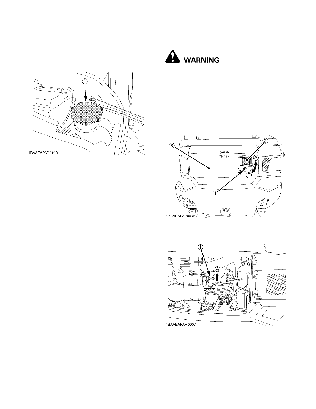
41MAINTENANCE
OPENING AND CLOSING OF PARTS
BOpening and Closing of the Fuel Tank Cap
To open the fuel tank cap, turn clockwise.
To close it, turn counterclockwise.
(1) Fuel tank cap
BOpening/Closing of the Engine Hood
To avoid personal injury or death:
A Do not open the engine hood with the engine
A Do not touch the exhaust muffler or the
Insert the key into the key slot and turn it clockwise to
unlock it. And pull the catch to open the hood.
To close the hood, push up the clasp and push the hood
until it locks automatically.
Turn the key counterclockwise to lock the hood.
running unless in an emergency.
exhaust pipe; serious burns can occur.
(1) Key slot
(2) Catch
(3) Engine hood
(1) Clasp (A) Push up to close
(A) "LOCK"
(B) "UNLOCK"
Page 64
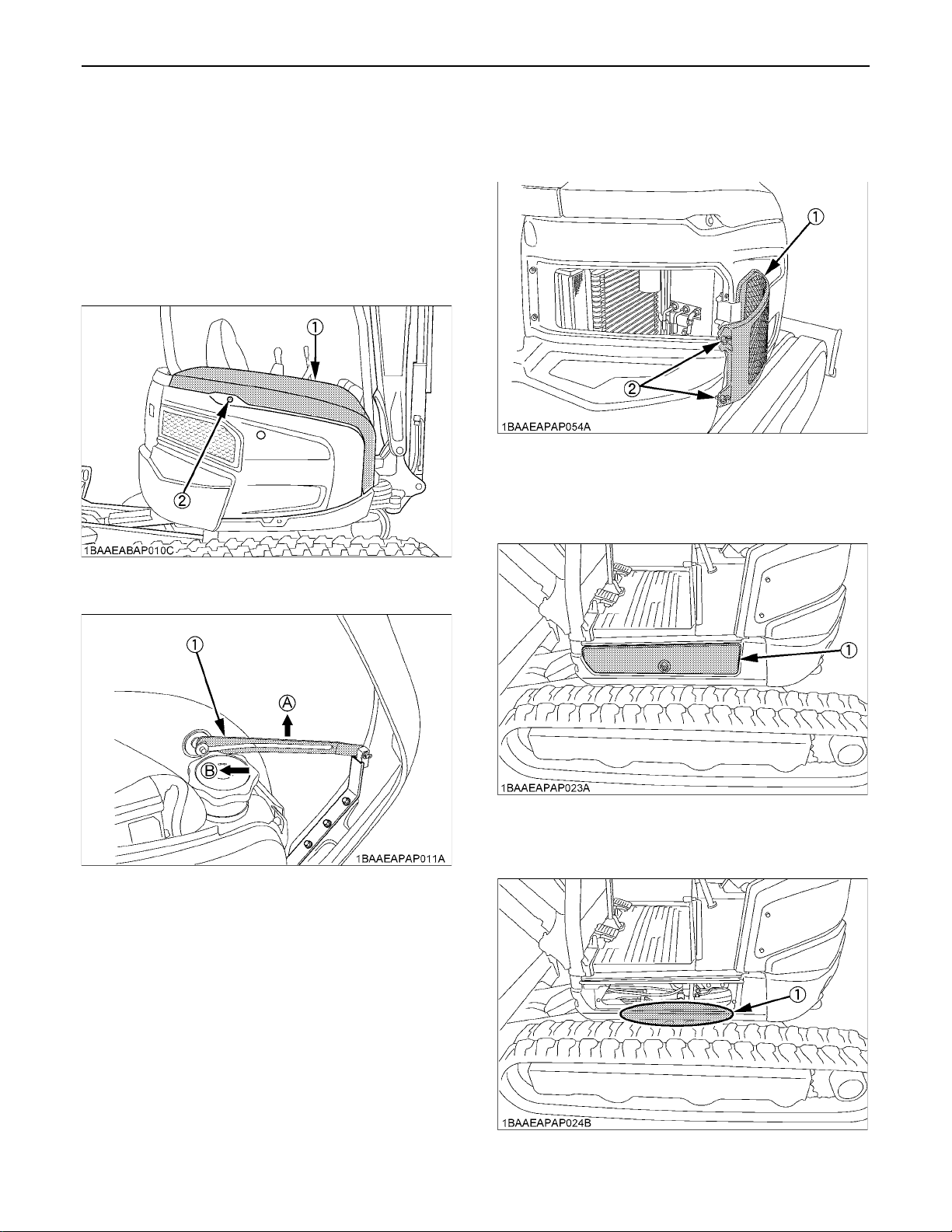
MAINTENANCE42
BOpening/Closing of the Side Cover
1. Insert the starter key in its hole and turn it clockwise to
unlock the side cover. Pull and hold up the side cover
until it is held by the link.
2. To close the side cover, push up the link, slide it left
and lower the side cover until it clicks into its closed
position.
3. Turn the starter key counterclockwise to get the side
cover locked.
(1) Side cover
(2) Key hole
BOpening/Closing of the Radiator Cover
Loosen the wing bolts and pull the radiator cover.
(1) Radiator cover
(2) Wing bolt
BOpening/Closing of the Swivel Frame
Cover
(1) Link (A) Push up
(B) Slide left
(1) Swivel frame cover
BWhere to store the Grease Gun
(1) Grease gun storage
Page 65
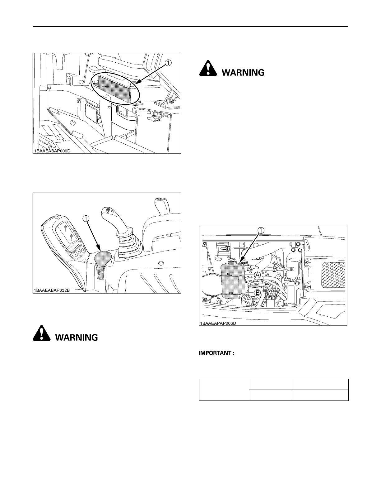
BWhere to keep Operator's Manual
(1) Operator's manual storage
BCup Holder
43MAINTENANCE
BChecking Coolant Level
To avoid personal injury or death:
A Move the excavator to even ground.
A Make sure that the engine is turned off.
A Do not open the radiator cap right after the
engine has been stopped; Serious burns can
occur from contact with escaping hot coolant
fluid.
A Check the coolant level in the recovery tank
only after the engine has cooled down.
A Remove the radiator cap only if absolutely
necessary.
1. Check to see that the coolant level is between the
"FULL" and "LOW" marks of the recovery tank.
2. When the coolant level drops due to evaporation, add
water only up to the full level.
In case of leakage, add anti-freeze and water in the
specified mixing ratio up to the full level.
(See "Changing Radiator Coolant" in every 2 years
maintenance.)
(1) Cup holder
DAILY CHECKS
To avoid personal injury or death:
A When operating, keep hands and body inside
of the ROPS / OPG (Top Guard Level I)
protective envelope.
A Do not touch the control levers and the pedals
from outside the cab while the engine is
running.
For your own safety and to assure the long life of your
machine, a careful check should be made before each
operation.
(1) Recovery tank (A) "FULL"
(B) "LOW"
A Do not fill the recovery tank over the "FULL" marking.
A Do not fill with dirty or salty water.
Radiator 2.4 L (0.54 US gal)
Coolant capacity
Recovery tank 0.6 L (0.16 US gal)
Page 66
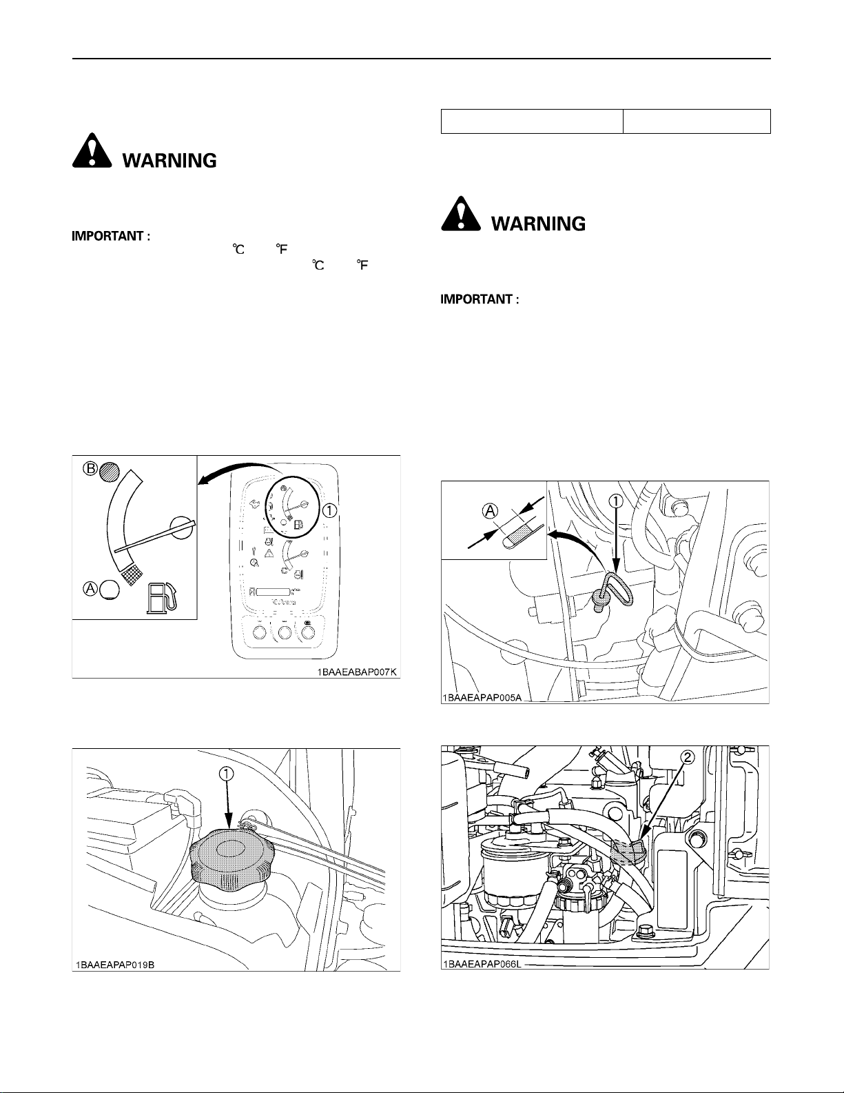
MAINTENANCE44
BChecking Fuel Level
To avoid personal injury or death:
A Stop the engine and remove the key before fuelling.
A Do not smoke while fuelling.
A By temperatures over -5 (+23 ), use No.2-D diesel
fuel, when temperatures are under -5 (+23 ), use
No.1-D diesel fuel.
A Make sure that the fuel tank will not run empty. Air will
enter the fuel system, and must be purged before
restarting the engine.
A See "PURGING FUEL SYSTEM" in "OTHER
ADJUSTMENTS AND REPLACEMENTS" section.
A To prevent condensation (water) accumulations in the
fuel tank, fill the fuel tank full before parking overnight.
1. Turn the starter key to the position "RUN".
2. Check the fuel level by the fuel level indicator.
Fuel tank capacity 33 L (8.7 US gal)
BChecking Engine Oil Level
To avoid personal injury or death:
A Stop the engine and remove the key before
checking the oil level.
A Use engine oil with the correct viscosity. (according to
the outside temperature)
A After stopping the engine and remove the key, wait 5
minutes, then check oil level. (Excavator must be on
level ground.)
Insert the engine oil dipstick fully into the respective port
opening, remove again and check the oil level; if
necessary fill with oil. The machine must be on level
ground when checking the oil level.
(1) Fuel gauge (A) "EMPTY"
(B) "FULL"
3. Open the tank cap, and add fuel.
(1) Fuel tank cap
(1) Engine oil dipstick (A) Required level
(2) Oil filling port
Page 67
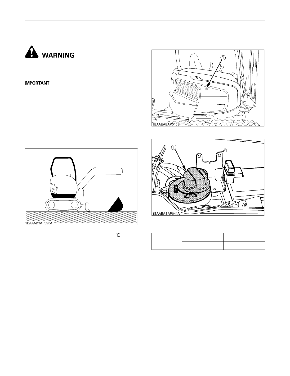
BChecking Hydraulic Oil Level
To avoid personal injury or death:
A Stop the engine and remove the key before
checking the oil level.
A Before filling oil, wipe away all sand and dust from
around the oil port. Make sure to use an identical type
of hydraulic fluid.
A The excavator has been filled with hydraulic fluid
before delivery. See "RECOMMENDED OILS"
section.
(Do not mix different oils.)
45MAINTENANCE
4. Should the oil level be too low, fill oil through the oil
port before starting the engine. This step is important
for the protection of the hydraulic system.
1. Park the excavator on a firm, flat and level surface.
Lower the attachments and dozer blade to the ground
and stop the engine.
2. Check the oil level as to whether it lies on the center of
the gauge at normal temperature (10 to 30 ).
3. Enough oil is present if the oil level lies near the center
of the gauge.
(1) Gauge
(1) Tank cap
Hydraulic oil
capacity
Hydraulic tank 22 L (5.8 US gal)
Whole oil volumes 37 L (9.78 US gal)
Page 68
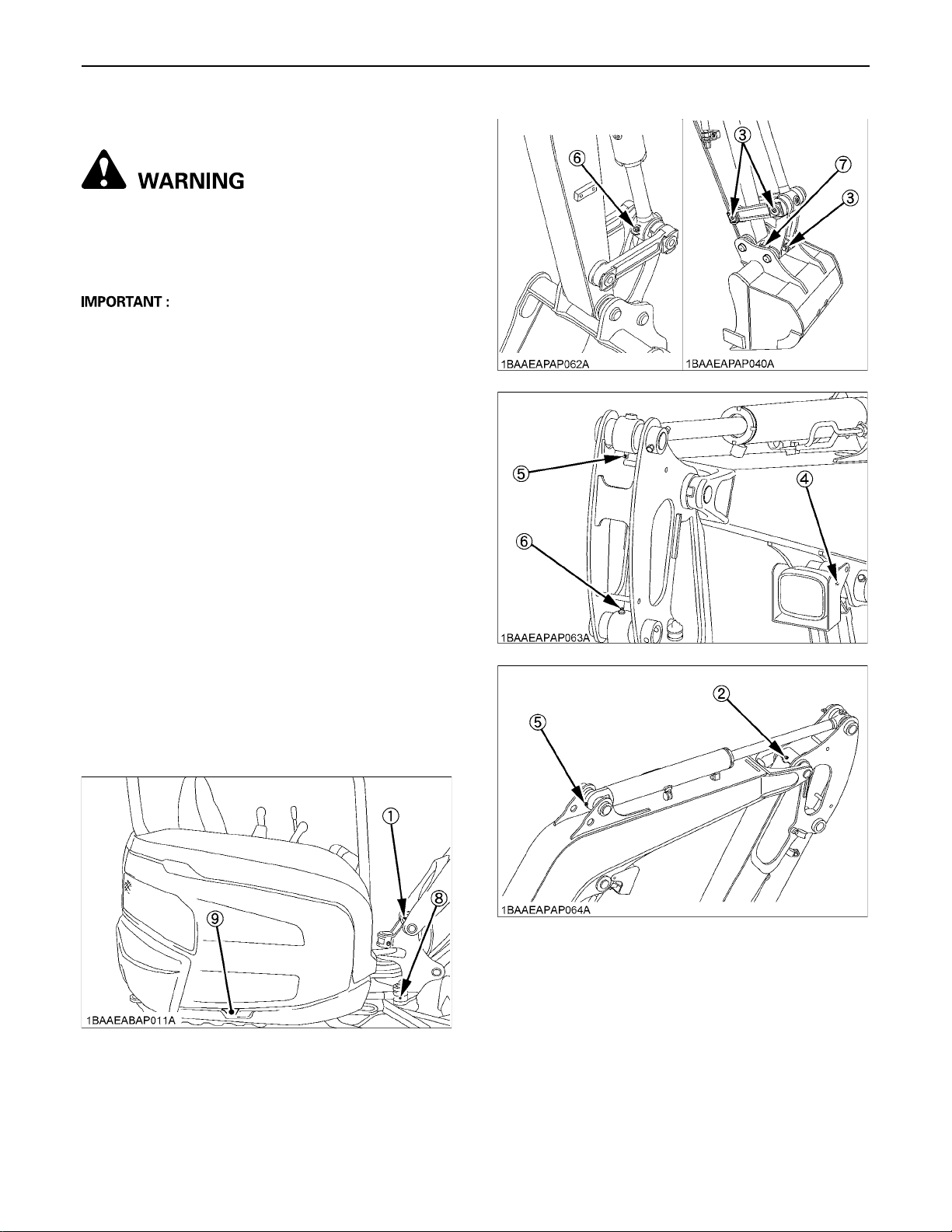
MAINTENANCE46
BLubrication Points
To avoid personal injury or death:
A First lower all attachments on the ground then
stop the engine and remove the key.
A While greasing, take care not to step on the
bucket teeth.
A When doing excavation work in water, generously
grease the following points. After ending work, grease
again.
Grease the marked grease fittings shown by arrows in the
illustration below.
1. Boom bottom linkage............................. 1 place
2. Arm bottom linkage................................ 1 place
3. Bucket link pin (or boss)......................... 3 places
4. Boom cylinder boss............................... 2 places
5. Arm cylinder boss.................................. 2 places
6. Bucket cylinder boss.............................. 2 places
7. Arm top linkage...................................... 1 place
8. Swing cylinder boss............................... 1 place
9. Swing cylinder bottom............................ 1 place
10. Swing pin............................................... 2 places
11. Dozer cylinder boss............................... 2 places
12. Dozer linkage pin................................... 2 places
Page 69

BCheck Fan Belt
To avoid personal injury or death:
A Stop the engine and remove the key before
checking the fan belt.
A Check the fan belt for cracks and proper
tension. (See "Checking Fan Belt Tension" in
"REGULAR CHECKS AND MAINTENANCE
WORK" section.)
BChecking Radiator and Oil Cooler
To avoid personal injury or death:
A Always stop the engine and remove the key
before checking the radiator.
A Wear eye protection when cleaning with
compressed air.
47MAINTENANCE
1. Check if the fins and ribs are clogged.
If so clean with compressed air or steam.
2. Check the rubber hoses for damage and replace if
cracked or old. Check if the hose clamps are tight
enough.
(1) Radiator
(2) Oil cooler
A Radiator and oil cooler fins and ribs must be clean in
order to avoid overheating the engine and to allow free
flow of air through the cooling elements.
A Pressure of compressed air must be under 205 kPa
(2.1 kgf.cm , 30 psi)
Page 70
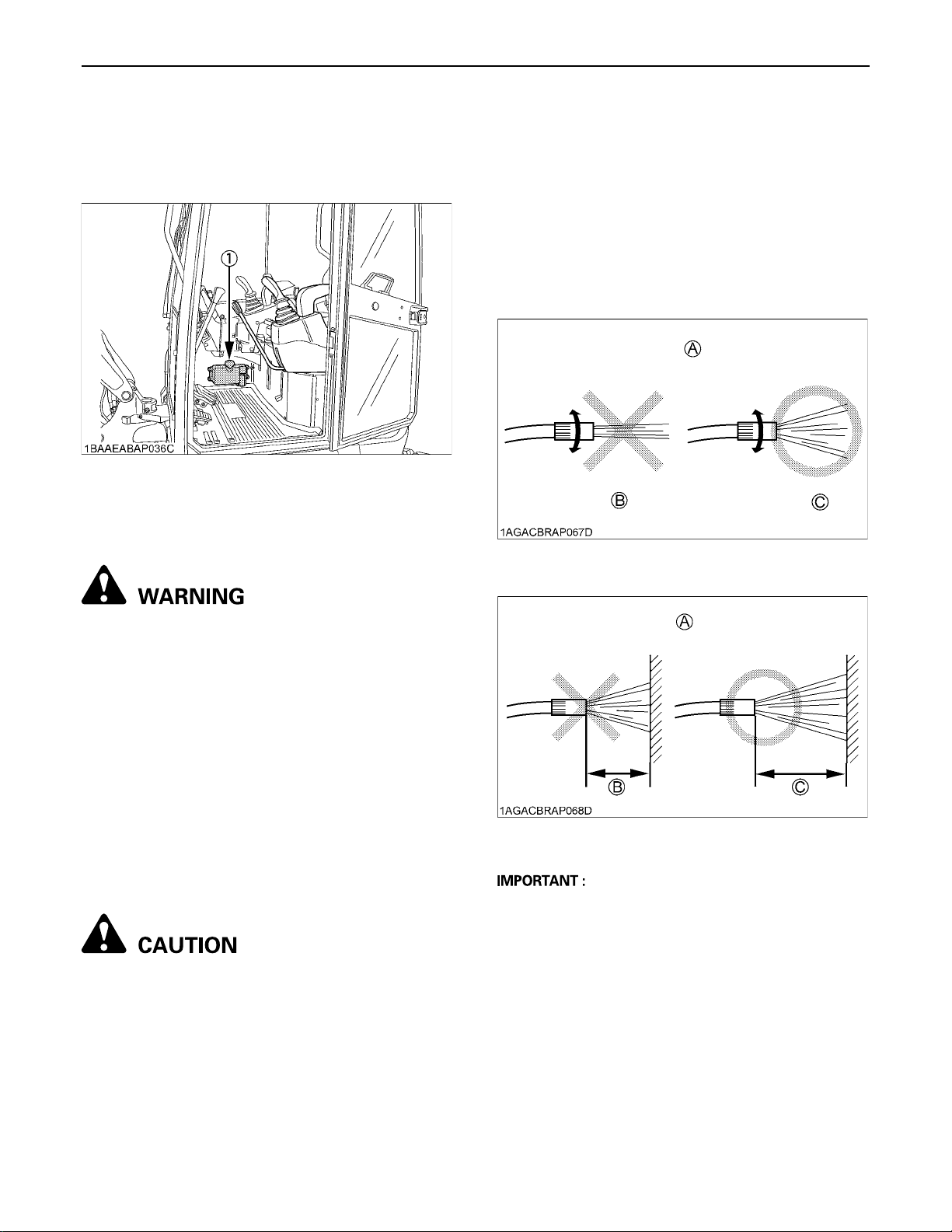
MAINTENANCE48
BChecking Washer Liquid (only for CAB
type)
If the windows washer is switched on with the washer
liquid tank empty, the motor may be damaged. Always
keep the tank filled.
(1) Washer liquid tank
BChecking and Cleaning Engine and
Electrical Wiring
3. It may cause damage or breakdown of the
machine.
Example) (1) Peeling of seals and labels
(2) Electronic components, engine
Breakdown due to interior
infiltration, etc.
(3) Damage to rubber, resin and
glass parts such as tires, oil
seals, etc.
(4) Peeling of paint and plated
surface
(A) Direct Wash Strictly Prohibited
(B) Direct
(C) Diffusion
To avoid personal injury or death:
A Always stop the engine and remove the key
before cleaning the wiring, cables and engine.
Before starting, check whether flammable substances
have gathered on the battery, the cables and wiring, the
muffler or on the engine. Remove thoroughly.
Check the electrical circuitry for disconnections, shorts or
loose terminals.
BWashing Whole Machine
The incorrect use of a high-pressure wash may result in
injuries or cause damage or breakdown of the machine.
Use a high-pressure wash according to its instruction
manual and labels.
To avoid personal injury:
Set the flushing nozzle to diffusion so as not to
damage the machine, then wash from 2m away.
Washing directly or from a close range may cause
following.
1. It may damage the coating on the electrical
wiring or disconnect the wires, which may
cause fire.
2. Damage to the hydraulic hose may cause high pressure oil to be ejected and cause injury.
(A) Close-Range Wash Strictly Prohibited
(B) Less than 2m
A Do not wash the excavator with the engine running.
Water could enter the air filter and damage the engine.
Make sure that the air filter is kept dry.
A Remove the mud before washing the machine.
(C) 2m or more
Page 71
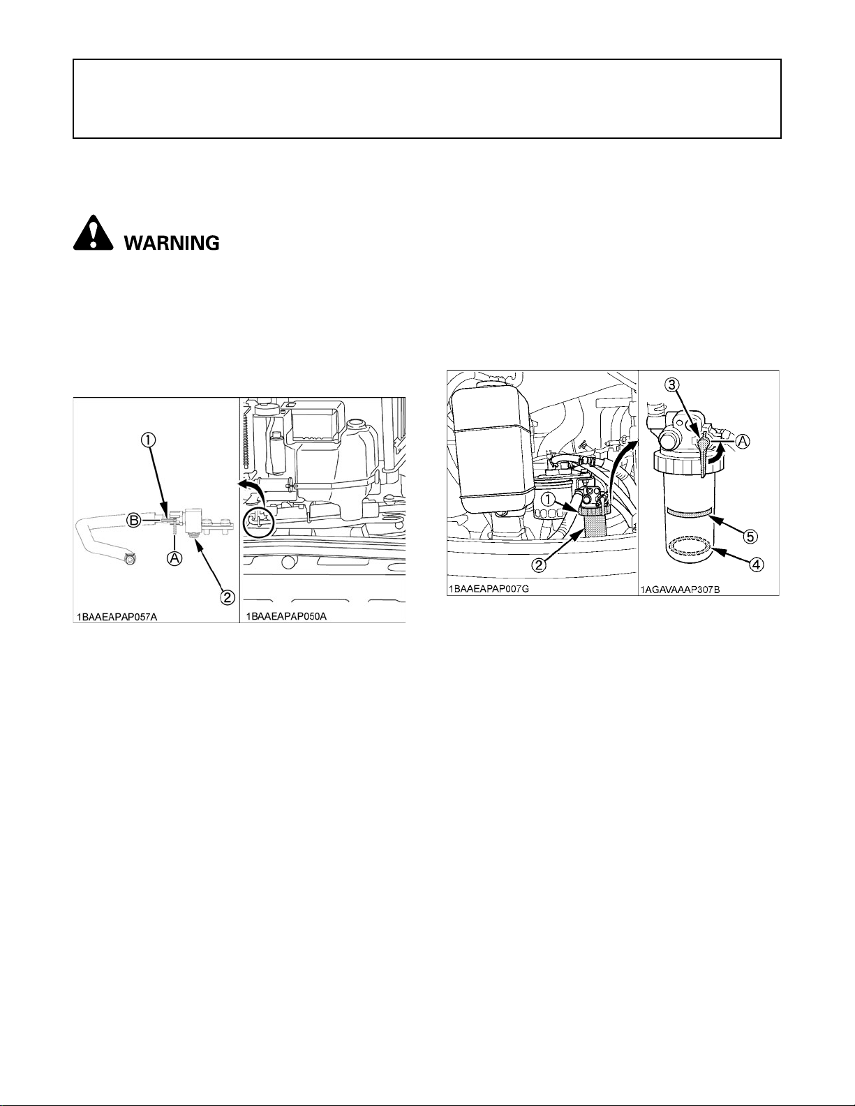
49REGULAR CHECKS AND MAINTENANCE WORK
REGULAR CHECKS AND MAINTENANCE WORK
EVERY 50 SERVICE HOURS
BDraining the Water from the Fuel Tank
To avoid personal injury or death:
A Before draining the water from the fuel tank, be
sure to stop the engine and remove the key.
A Do not smoke during inspection.
1. Turn the drain shutoff-valve to "CLOSED" position
and remove the drain plug.
2. Turn the drain shutoff-valve to "OPEN" position and
drain water.
BDraining Water Separator
1. Open the hood.
2. When the separated water is being drained, the red
float moves upward.
When the float reaches the indication line, close the
shutoff-valve so that no fuel can run out. Now loosen
the ring nut, and remove the cup and empty
completely.
3. Clean carefully not to damage the filter element.
4. Finally, do not forget to open the shutoff-valve and
close the hood.
(1) Drain shutoff-valve
(2) Drain plug
(A) "CLOSED"
(B) "OPEN"
(1) Ring nut
(2) Cup
(3) Shutoff-valve
(4) Float
(5) Line
(A) "CLOSE"
Page 72
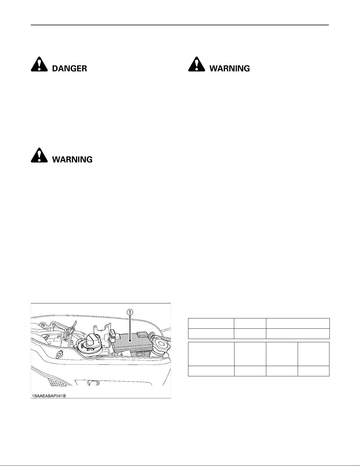
REGULAR CHECKS AND MAINTENANCE WORK50
BBattery
To avoid the possibility of a battery explosion:
For refillable type battery, follow the instructions
below.
A Do not use or charge the refillable type battery
if the fluid level is below the LOWER (lower limit
level) mark. Otherwise, the battery component
parts may prematurely deteriorate, which may
shorten the battery's service life or cause an
explosion. Check the fluid level regularly and
add distilled water as required so that the fluid
level is between the UPPER and LOWER levels.
To avoid personal injury or death:
A Never remove the vent caps while the engine is
running.
A Keep electrolyte away from eyes, hands and
clothes. If you are spattered with it, wash it
away completely with water immediately and
get medical attention.
A Wear eye protection and rubber gloves when
working around the battery.
A Before inspection or dismounting the battery,
be sure to turn off the engine and turn the
starter switch to the "STOP" position.
A When removing the battery, always disconnect
the negative ground cable first. When installing
a battery, always connect the ground cable
last. This prevents a possible explosion caused
by sparks.
A Always wear eye protection when working with
the battery.
BBattery Charging
To avoid personal injury or death :
A When the battery is being activated, hydrogen
and oxygen gases in the battery are extremely
explosive. Keep open sparks and flames away
from the battery at all times, especially when
charging the battery.
A When charging battery, remove battery vent
plugs.
A When disconnecting the cable from the battery,
start with the negative terminal first.
When connecting the cable to the battery, start
with the positive terminal first.
A Do not check battery charge by placing a metal
object across the terminals.
Use a voltmeter or hydrometer.
1. Make sure each electrolyte level is to the bottom of
vent wells. If necessary add distilled water in a wellventilated area.
2. The water in the electrolyte evaporates during
recharging. Liquid shortage damages the battery.
Excessive liquid spill damages the excavator body.
3. To slowly charge the battery, connect the battery
positive terminal to the charger’s positive terminal and
the negative to the negative one. Then, recharge in the
standard fashion.
4. A boost charge is only for emergencies. It will partially
charge the battery at a high rate and in a short time.
When using a boost-charged battery, it is necessary to
recharge the battery as early as possible.
Failure to do this will shorten the battery's service life.
5. When the specific gravity of electrolyte falls between
1.27 and 1.29, charge has completed.
6. When exchanging old battery for a new one, use
battery of equal specification.
(1) Battery
Battery Type Volts (V) Capacity
56219 12 55 (at 5H.R(A.H))
Reserve
Battery Type
56219 103 550 15
Capacity
(min)
Cold
Cranking
Amps
Normal
Charging
Rate (A)
Page 73
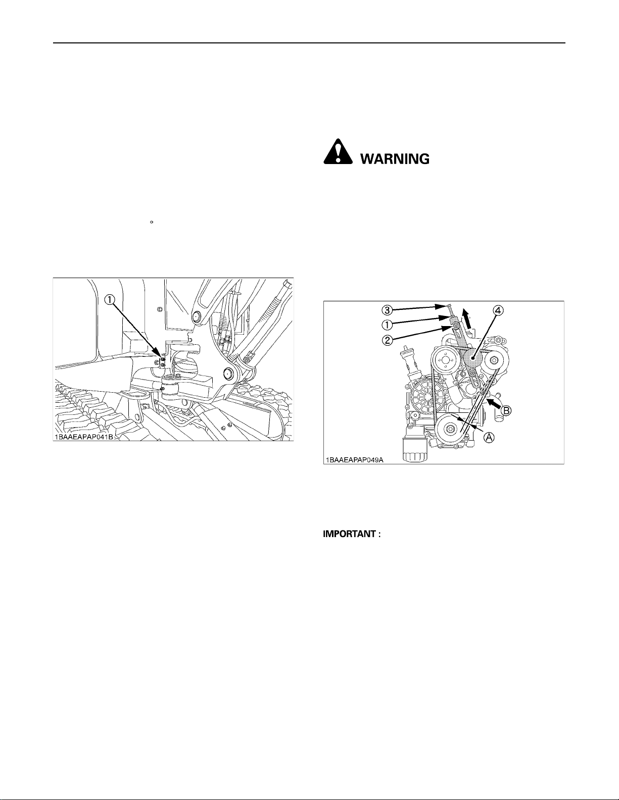
51REGULAR CHECKS AND MAINTENANCE WORK
C Direction for Storage
1. When storing the machine for long periods of time,
remove the battery from machine, adjust the
electrolyte to the proper level and store in a dry place
out of direct sunlight.
2. The battery self-discharges while it is stored.
Recharge it once every three months in hot seasons
and once every six months in cold seasons.
BGreasing of Swing Bearing Teeth
1. Pump grease with grease gun through the grease
fitting.
2. Grease at each 90 (1.58 rad.) position of the swing
frame.
3. Fill with approx. 50g of grease (approx. 20 pumps with
the grease gun). Distribute the grease over the teeth.
EVERY 200 SERVICE HOURS
Do all 50 hour servicing at the same time.
BChecking Fan Belt Tension
C Check and adjustment of the fan belt tension
To avoid personal injury or death:
A First stop the engine and remove the key.
A After servicing, make sure to replace the belt
cover in its original position.
1. Press the fan belt down in the middle, with a force of
approx. 7 kg (15.41 lbs). The belt tension is correct if it
deflects about 7 mm (0.28 in.). If otherwise, loosen nut
(1) and bolt (2) and turn bolt (3) clockwise to shift the
tension pulley (4) in the direction shown by the arrow.
2. Replace the fan belt if worn out, cracked or torn.
(1) Grease fitting (for Bearing teeth)
(1) Nut
(2) Bolt
(3) Bolt
(4) Tension pulley
A If the engine is run with a loose fan belt, the belt could
slip and cause overheating of the engine or insufficient
battery charging. Check fan belt tension regularly.
A Should the fan belt break or jump off, the indicator light
for battery charge will light up. Stop the engine and
remove the key immediately.
(A) about 7 mm (0.28 in.)
(B) approx. 7 kg (15.41 lbs)
Page 74
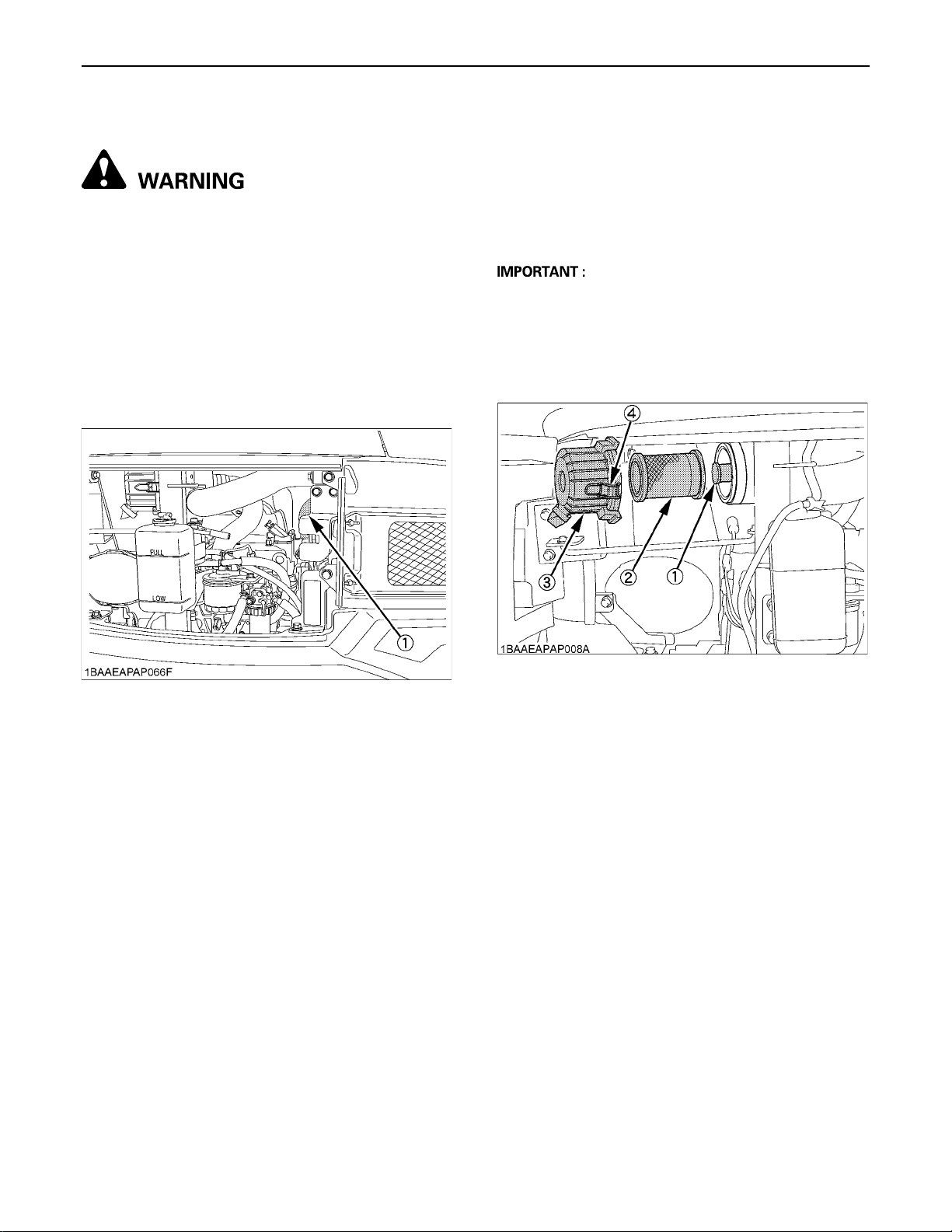
REGULAR CHECKS AND MAINTENANCE WORK52
BChecking Radiator Hoses and Clamps
To avoid personal injury or death:
A Wait long enough for the radiator coolant to
cool down.
Check the water hoses for proper connection. This check
should be carried out every 200 hours or every 6 months,
whichever comes first.
1. Should the hose clamps become loose or water leaks,
tighten the hose clamps properly.
2. Should the radiator hoses become swollen, aged or
cracked, they must be replaced and the hose clamps
tightened again properly.
BInspection and Cleaning Air Filter Element
Open the engine hood and remove the dust-cover. Take
out only outer element, clean the element, case interior
and reassemble. During reassembly, take care to install
the dust-cover so that its TOP mark (arrow) faces upwards. Do not remove the inner element.
A Should the machine be used in extremely dusty areas,
the air filter element must be inspected and cleaned
more frequently than in the specified maintenance
periods.
A The air filter has a dry element, keep free from oil.
A Do not run the engine without the air filter.
(1) Radiator hoses
(1) Inner element
(2) Outer element
(3) Dust-cover
(4) Clamps
Page 75
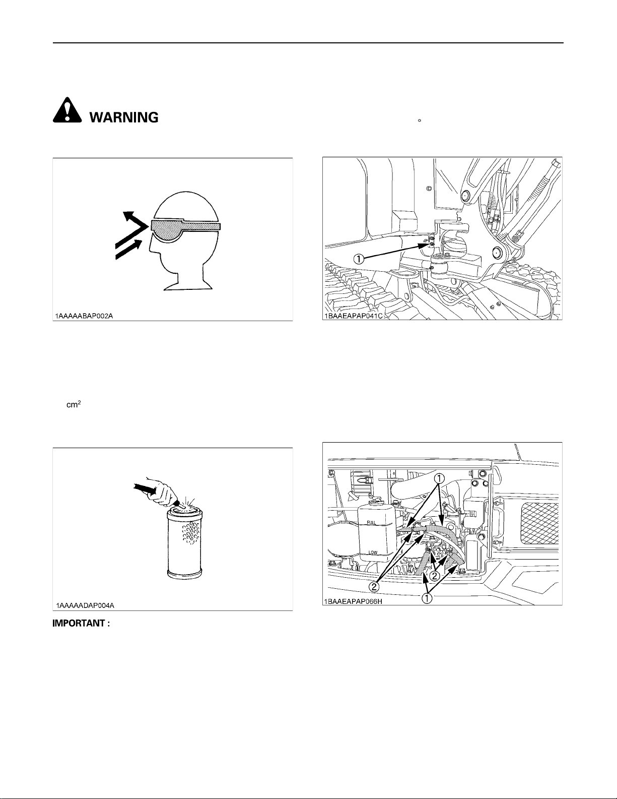
53REGULAR CHECKS AND MAINTENANCE WORK
BAir Filter Maintenance
To avoid personal injury or death:
A Wear eye protection.
The quickest and safest method of maintenance is the
exchange of the paper cartridge. Furthermore there are
different methods of cleaning the cartridge.
C Cleaning with compressed air
Pressure of compressed air must be under 205 kPa (2.1
kg/ , 30 psi), and the cartridge should be blown clean
from the inside to the outside until the dust deposits are
remarkably reduced.
BGreasing Swing Bearing
1. Grease through the respective grease fitting. (at the
lower fitting)
2. Grease at each 90 (1.58 rad.) position of the swing
frame.
3. Using the grease gun, apply 5 shots at every position.
(1) Grease fitting
BChecking Fuel Line and Intake Air Line
1. Check to see that all lines and hose clamps are
tightened and not damaged.
2. If hoses and clamps are found worn or damaged,
replace or repair them at once.
A If the air suction is still inadequate, or the colour of the
exhaust gases is abnormal even after the cleaning, the
air filter element must be replaced.
(1) Hoses
(2) Hose clamps
Page 76
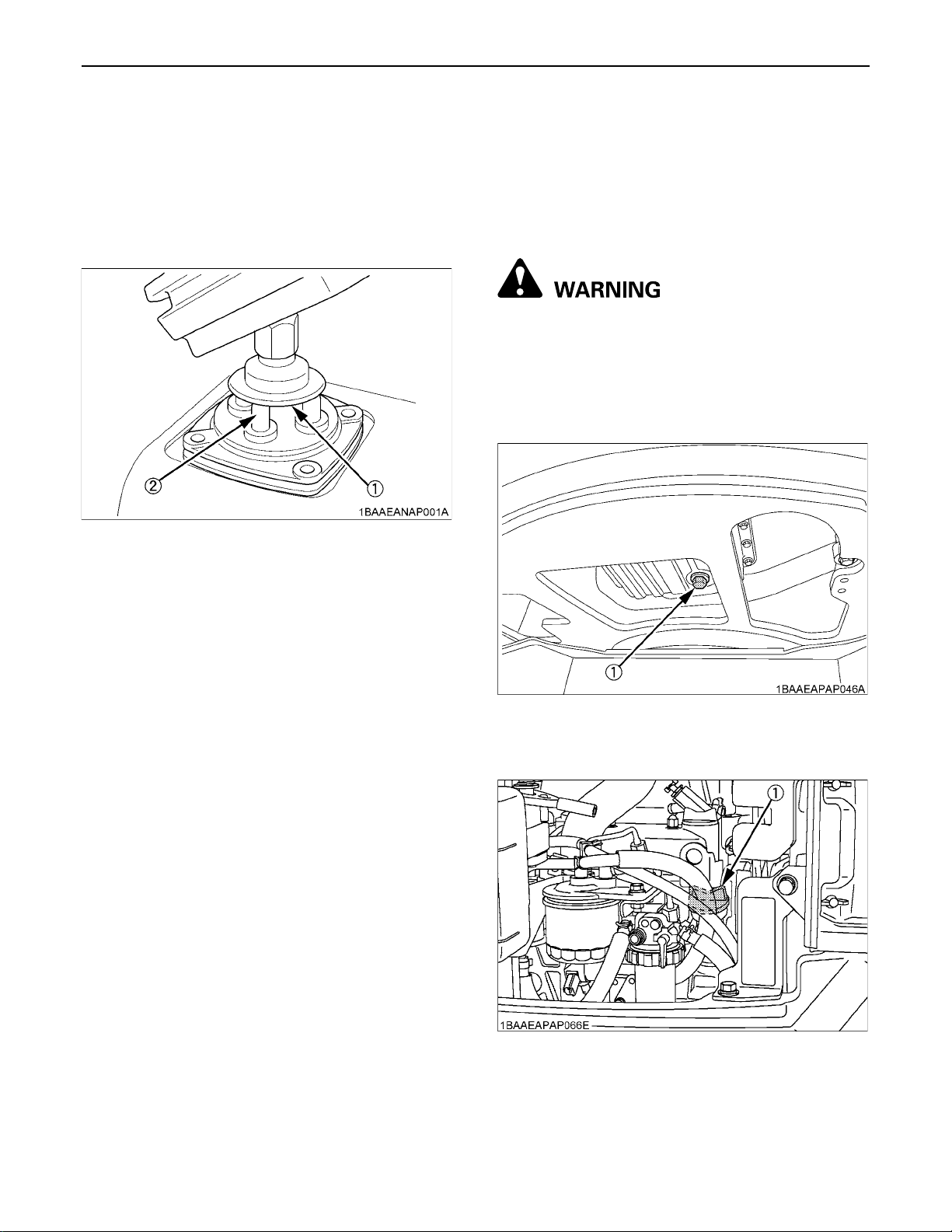
REGULAR CHECKS AND MAINTENANCE WORK54
EVERY 250 SERVICE HOURS
Do all 50 hour servicing at the same time.
BLubrication of the Pilot Valve
Remove the rubber bellows from the underside of the
control levers. Grease the tip of the push rod and the
rotating part of the link.
(1) Rotating port of the link
(2) Tip of the push rod
EVERY 500 SERVICE HOURS
Do all 50 and 250 hour servicing at the same time.
BChanging Engine Oil (Change the engine
oil every 500 hours, or every 1 year in the
case that service hour is less than 500
hours)
To avoid personal injury or death:
A First stop the engine then remove the key and
wait long enough for the oil to cool down.
1. Remove the drain plug on the underside of the engine
and drain all oil.
2. Re-tighten the drain plug.
(1) Drain plug
3. Fill up with new oil through the filling port to the
specified level.
(1) Oil filling port
(2) Engine oil dipstick
(A) Required oil level range
Page 77
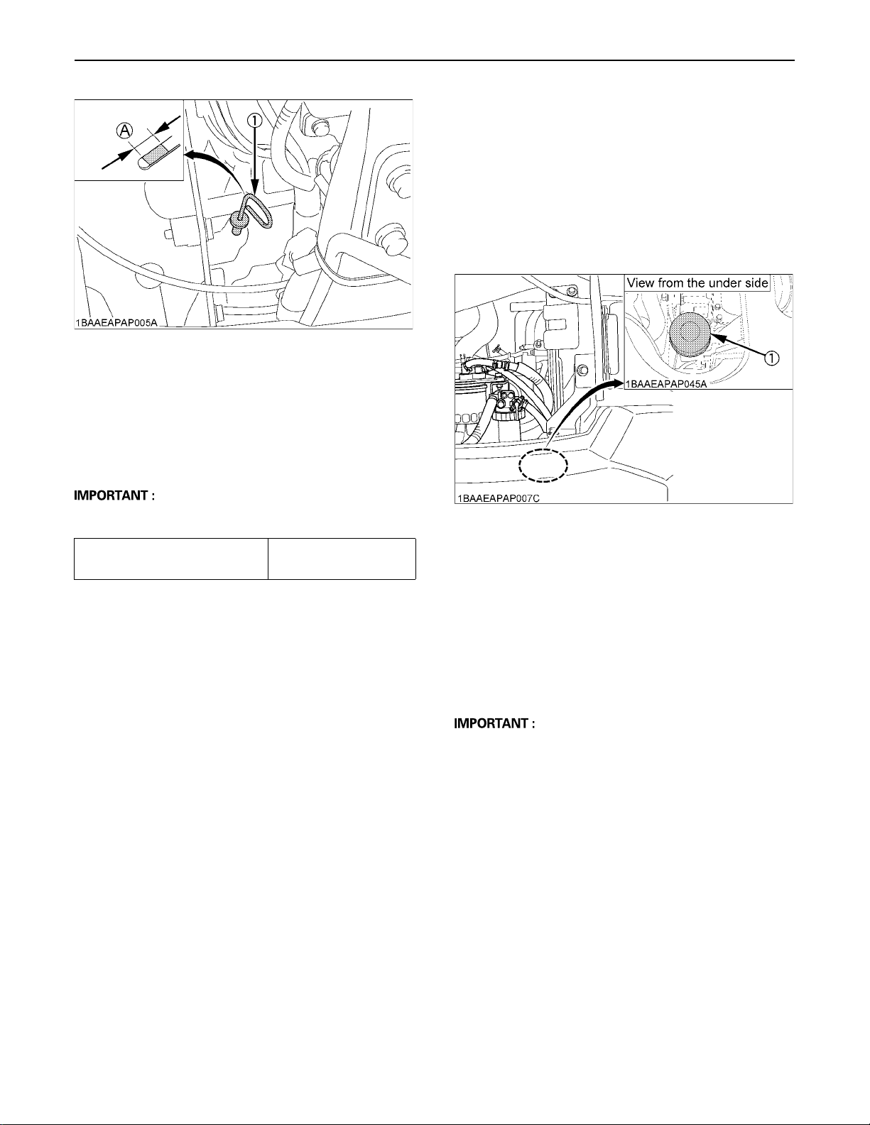
(1) Engine oil dipstick (A) Oil level is acceptable within
this range.
4. Let the engine idle for approx. 5 min. Check the engine
oil level. To check the engine oil level, insert the
engine oil dipstick completely into the respective port
opening and pull out again. If the oil level lies between
both markings, no oil must be added.
55REGULAR CHECKS AND MAINTENANCE WORK
BReplacing Engine Oil Filter Cartridge
(Replace the engine oil filter cartridge
every 500 hours,or every 1 year in the
case that service hour is less than 500
hours)
1. Replace the oil filter cartridge at the same time as
doing the engine oil change.
2. Remove the cartridge with the supplied filter wrench.
A Regardless of the service hours, an engine oil change
is due every 6 month.
Engine oil capacity
(with engine oil filter)
4.4 L (1.16 US gal)
(1) Oil filter cartridge
3. Oil the O-ring of the new oil filter cartridge lightly. Then
tighten the oil filter cartridge by hand.
4. Fill engine oil to the specified level.
5. Let the engine run for approx. 5 min. and make sure
that the engine oil indicator lamp does not light up.
Then stop the engine and remove the key.
6. The engine oil level is reduced by the amount of the
filter capacity after the engine is started. It is necessary
to add oil.
A Always check the oil level after having exchanged the
filter.
Page 78
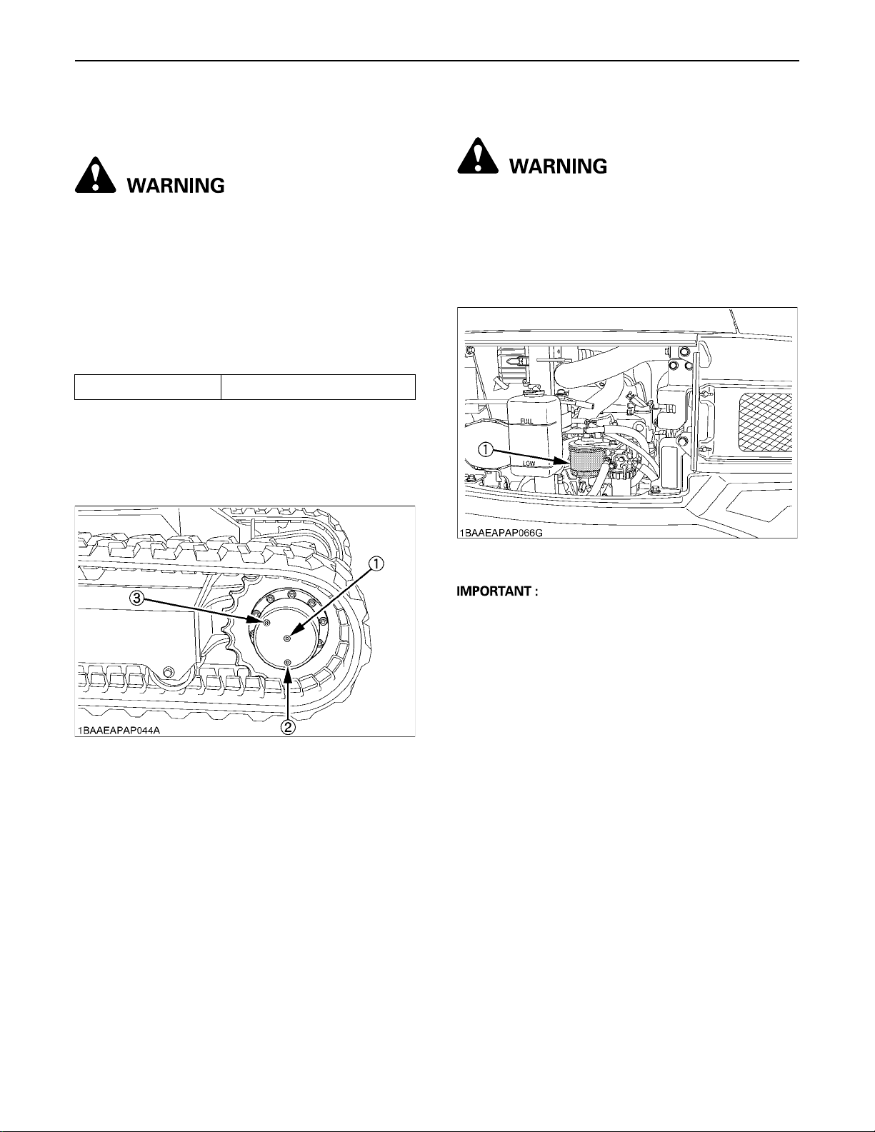
REGULAR CHECKS AND MAINTENANCE WORK56
BDrive unit Oil Change(First Oil Change of
the 50 hours)
To avoid personal injury or death:
A Lower all attachments to the ground, stop the
engine and remove the key before undertaking
the oil change.
1. Rotate the track so that the drain plug of the drive unit
is in the bottom position.
2. Remove the drain plug to let the oil run out. Screw in
and tighten the drain plug again and fill with gear oil
through the oil check port.
3. Fill oil until it overflows out of the oil check port.
Gear oil capacity approx. 0.35 L (0.77 US gal)
Oil change
- first oil change after 50 hrs
- then every 500 hrs
- or at least once a year
4. Use prescribed gear oil SAE 90.
BReplacing Fuel Filter Cartridge
To avoid personal injury or death:
A Keep fire away.
1. Remove the filter with the supplied filter wrench.
2. Add fuel to a new filter before installing.
3. Apply a light film of fuel to the seal of the new filter and
turn in tightly by hand.
4. Open the shutoff-valve of the fuel filter again.
(1) Oil check port
(2) Drain port
(3) Filling port
(1) Fuel filter cartridge
A After exchange of the filter, the fuel system must be
purged of air.
Page 79
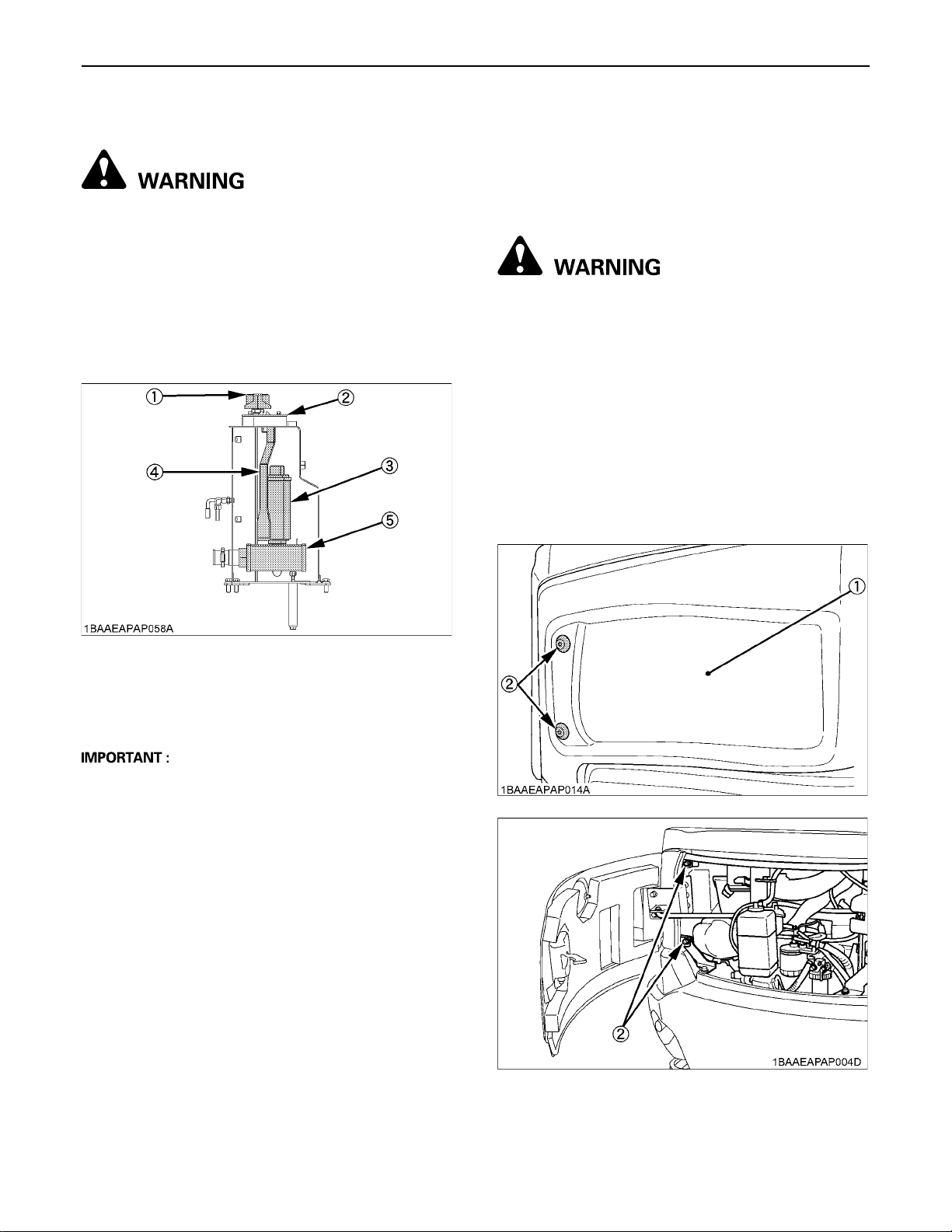
57REGULAR CHECKS AND MAINTENANCE WORK
BReplacing Hydraulic Return Filter Element
To avoid personal injury or death:
A Remove the oil filter element only after the oil in
the hydraulic tank has cooled down.
1. Hold the filter support top and take the filter out of the
tank.
2. Loosen the set bolt first and then detach the return
filter from its support. Replace the filter with new one.
3. Remove the bolt from the cover. Take out and replace
the breather filter with new one.
EVERY 1000 SERVICE HOURS
Do all 50, 200, 250 and 500 hour servicing at the same
time.
BReplacing the Hydraulic Pilot Filter
Element
To avoid personal injury or death:
A Before replacing the element, wait long enough
for the hydraulic fluid to cool down.
1. Remove four bolt and detach the left side cover.
2. Remove the pilot filter case from the head cover.
3. Wrench and pull out the element downward.
4. Replace the O-ring with a new one.
5. Apply a light coating of clean hydraulic oil to the O-ring
and fit it to the case firmly. Be careful not to scratch the
O-ring.
6. Fit the case to the head cover.
7. Let the engine run for approx. 3 minutes.
8. Check the oil level of hydraulic oil tank.
(1) Breather filter
(2) Cover
(3) Return filter
(4) Filter support
(5) Suction filter
A Always check the oil level when replacing the filter.
(1) Left side cover
(2) Bolt
Page 80
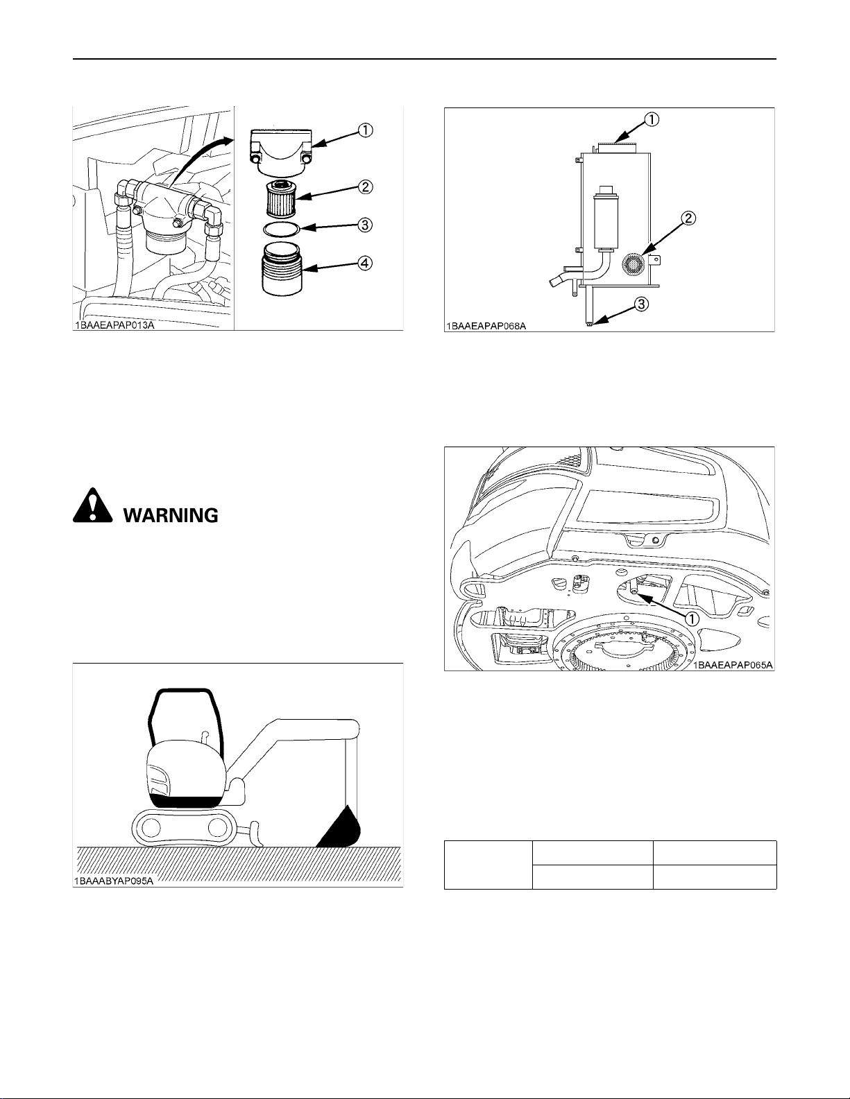
REGULAR CHECKS AND MAINTENANCE WORK58
(1) Head cover
(2) Element
(3) O-ring
(4) Case
BHydraulic Oil Change (Including
Replacing of the Suction Filter in the
Hydraulic Tank)
To avoid personal injury or death:
A Wait long enough for the hydraulic fluid to cool
down. Then begin with the change of the
hydraulic fluid.
1. Move the excavator to a level ground and stop the
engine. Extend the piston rods of the cylinders halfway
out and lower the bucket on the ground.
(1) Cover
(2) Suction filter
(3) Drain plug
2. Remove the drain plug on the underside of the
hydraulic tank and drain the oil.
(1) Drain plug
3. Remove the cover of the hydraulic tank.
4. With a fork wrench or similar, remove and exchange
the suction filter.
5. Retighten the drain plug.
6. Fill oil through the oil filling opening on the top side of
the tank.
7. Let the engine run for approx. 5 min. and check the oil
level again.
Hydraulic oil
capacity
Hydraulic tank 22 L (5.8 US gal)
Whole oil volumes 37 L (9.78 US gal)
Page 81
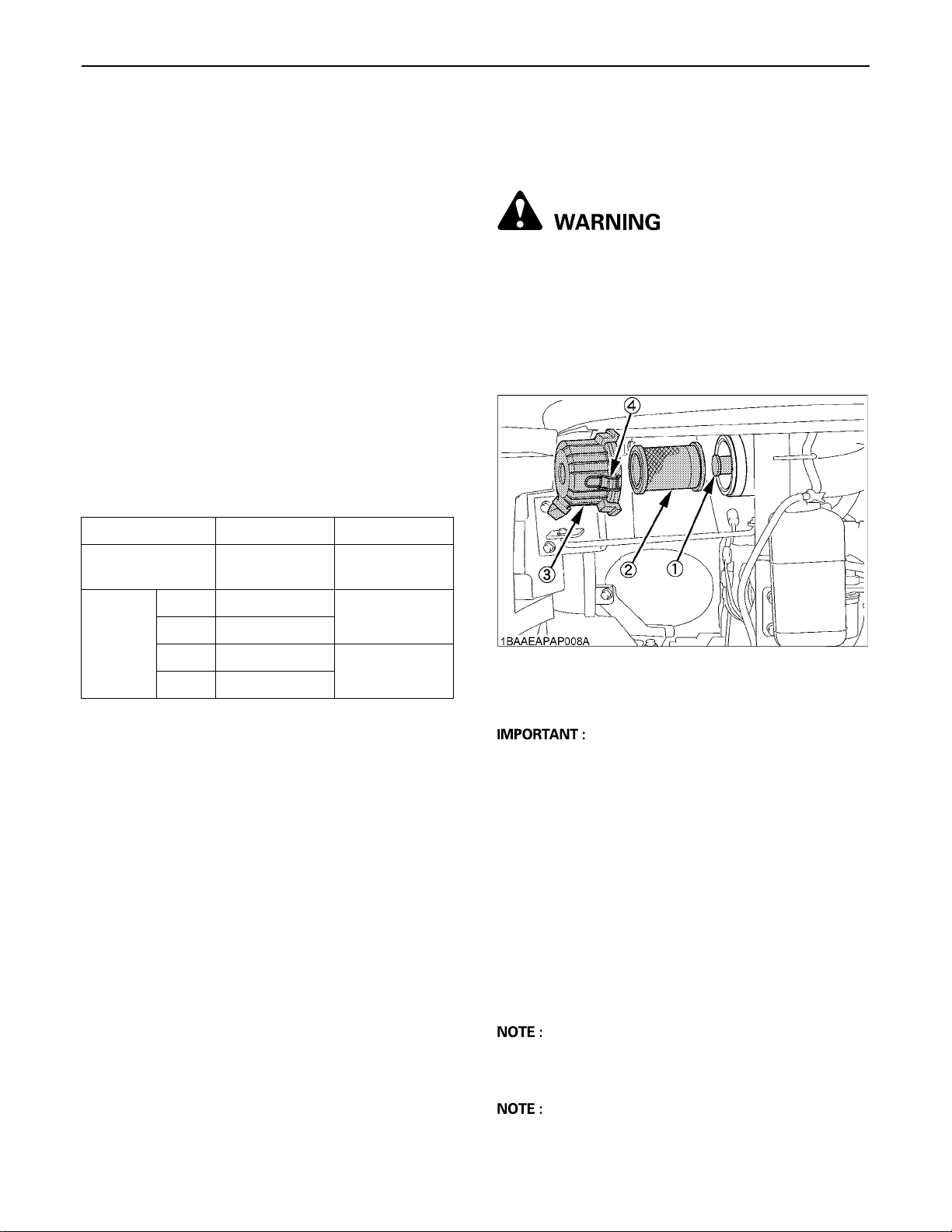
59REGULAR CHECKS AND MAINTENANCE WORK
BHydraulic Oil Check with Hydraulic
Breakers
The hydraulic oil change after 1000 operating hours in the
operator's manual is based on normal excavator work.
Following inspection measures are valid when hydraulic
breakers are used:
1. Changing and filling up of hydraulic oil
(1) The hydraulic oil must be changed more often
when breakers are used because the machine is
subject to harder conditions than at normal
excavating work.
(2) Use only the recommended oils mentioned in the
operator's manual when changing or fill oil.
(3) When filling up oil, do not mix oils of different
makes.
2. Changing the return filter and oil
(1) The filter must be changed more often because of
contamination resulting from the frequent
assembly and disassembly of the hoses.
(2) Use the correct replacement filter.
(3) Oil change according to operating hours.
Hydraulic oil Return filter
Normal excavator
work
every 1000 Hrs. every 500 Hrs.
EVERY 1000 SERVICE HOURS OR ONCE A YEAR
BReplacing Air Filter Element
To avoid personal injury or death:
A First stop the engine and remove the key.
Open the engine hood and remove the dust-cover.
Remove and replace the outer element and inner element
with new elements.
When reassembling, install the dust-cover so that its TOP
mark (arrow) faces up-wards.
Breaker
work
portion
20% every 800 Hrs.
40% every 400 Hrs.
60% every 300 Hrs.
more every 200 Hrs.
every 200 Hrs.
every 100 Hrs.
(1) Inner element
(2) Outer element
(3) Dust-cover
(4) Clamps
A Shorten the replacement period if the machine is used
in dusty or sandy areas.
EVERY 1500 SERVICE HOURS
BChecking Fuel Injection Nozzle (Injection
Pressure)
Consult your local KUBOTA dealer for this service.
EVERY 2000 SERVICE HOURS
Do all 50, 200, 250, 500 and 1000 hour servicing at the
same time.
BChanging Front Idler and Track Roller Oil
A Contact your KUBOTA dealer for details.
BChecking the Alternator and Starter Motor
A Contact your KUBOTA dealer for details.
Page 82
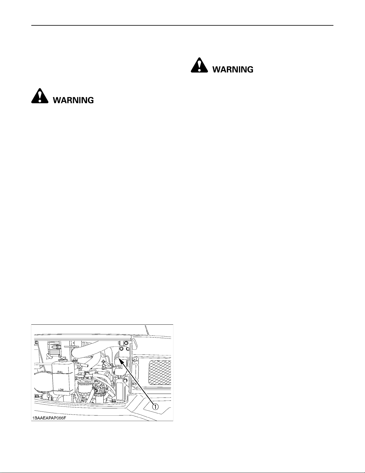
REGULAR CHECKS AND MAINTENANCE WORK60
EVERY 3000 SERVICE HOURS
BChecking Injection Pump
Consult your local KUBOTA dealer for this service.
ANNUAL SERVICING
To avoid personal injury or death:
A Always check the wire harness and battery
cord, as damage to these may cause a short
circuit.
A Check for dust and fuel deposited on the
battery, wiring, muffler and around the engine
as they may cause fire.
BElectrical Wiring and Fuses
Check the terminals periodically for proper connections.
Loose wiring or damaged cables can cause improper
functioning or short circuiting of the electrical system.
Check wiring and replace damaged components
immediately. If a fuse blows out soon after having been
replaced, contact your nearest KUBOTA dealer. Never
use a fuse other than specified.
BChecking the Electrical Circuit
Check the electrical circuitry for disconnections, shorts or
loose terminals.
BIENNIAL SERVICING
BReplacement of Radiator Hoses and Hose
Clamps
Replace radiator hoses and hose clamps every two years.
If the hoses are swollen, hard or cracked, they must be
replaced earlier.
BChanging Radiator Coolant
To avoid personal injury or death:
A Do not loosen the radiator cap before the
radiator has cooled down sufficiently. Then
only loosen the cap and allow enough time for
the pressure in the system to be released. Now
remove the cap completely.
A When using anti-freeze, put on some protection
such as rubber gloves. (Anti-freeze contains
poison.)
A If you accidentally swallowed anti-freeze, seek
medical attention at once.
A When anti-freeze comes in contact with the
skin or clothing, wash it off immediately.
A Do not mix different types of Anti-freeze. The
mixture can produce chemical reaction
causing harmful substances.
A Anti-freeze is extremely flammable and
explosive under certain conditions. Keep fire
and children away from anti-freeze.
A When draining fluids from the engine, place
some container underneath the engine body.
A Do not pour waste onto the grounds, down a
drain, or into any water source.
A Also, observe the relevant environmental
protection regulations when disposing of antifreeze.
A If swallowed, anti-freeze is poisonous to
people, animals and birds.
(In case of long-life coolant fluid)
Stop the engine then remove the key and wait until it has
cooled down completely.
1. Open the drain plug or shutoff-valve on the bottom of
the radiator and drain coolant completely.
2. To clean, rinse the radiator with water.
3. Close the drain plug or shutoff-valve and fill the
radiator and the recovery tank with coolant fluid. Let
the engine idle for about 5 min., stop the engine and
check the coolant level then remove the key.
4. The machine has been shipped filled with 50% antifreeze solution.
(1) Radiator hoses
Page 83
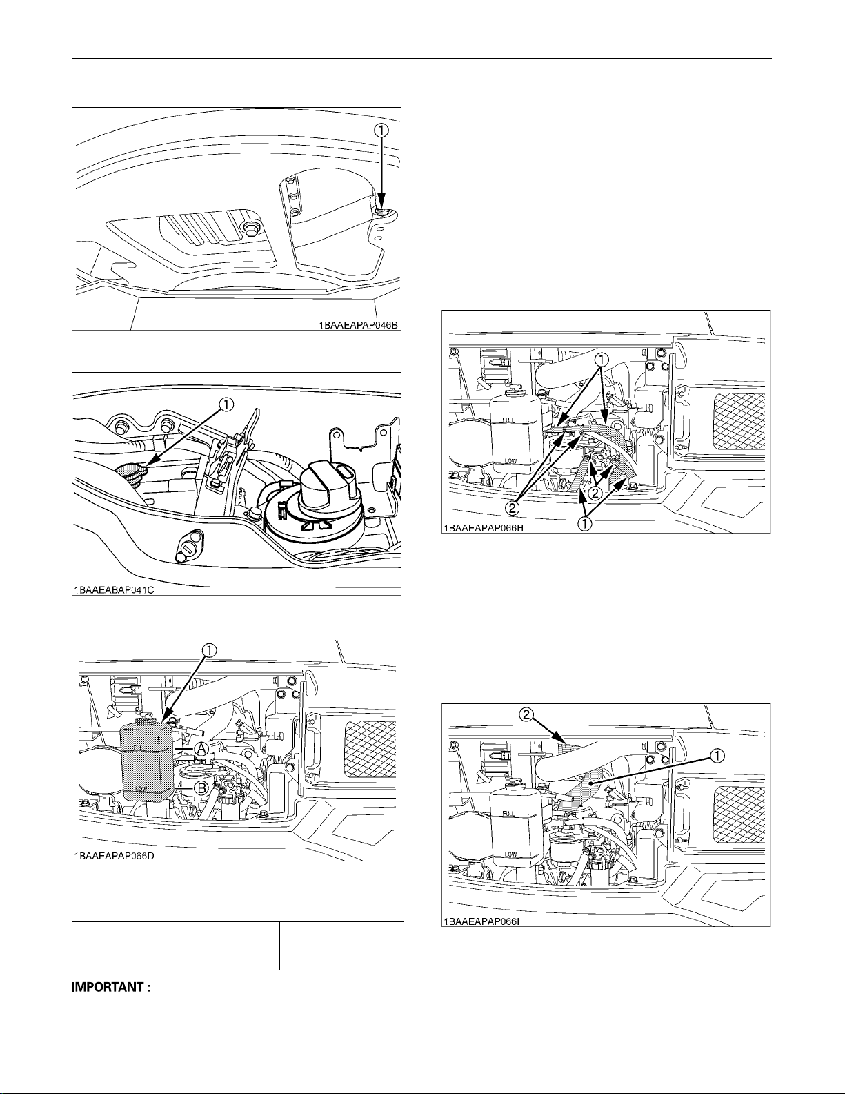
(1) Drain plug
61REGULAR CHECKS AND MAINTENANCE WORK
A To fill the radiator system use fresh water and anti-
freeze fluid.
A When the anti-freeze is mixed with water, the anti-
freeze mixing ratio must be less than 50%.
A Tighten the radiator cap properly. If the cap is loosely
or not properly fitted, overheating of the engine can
result due to coolant fluid loss.
BReplacing Fuel Hoses and Hose Clamps
Replace the hoses and clamps.
(See "Checking Fuel Line and Intake Air Line" in "EVERY
200 SERVICE HOURS")
(1) Radiator cap
(1) Recovery tank (A) "FULL"
(B) "LOW"
Radiator 2.4 L (0.54 US gal)
Coolant capacity
Recovery tank 0.6 L (0.16 US gal)
(1) Fuel lines
(2) Clamp bands
BReplacing Intake Air line
Replace the hoses and clamps, if necessary.
(See "Checking Fuel Line and Intake Air Line" in "EVERY
200 SERVICE HOURS")
(1) Hoses
(2) Hose clamps
A Do not operate the engine without coolant.
Page 84
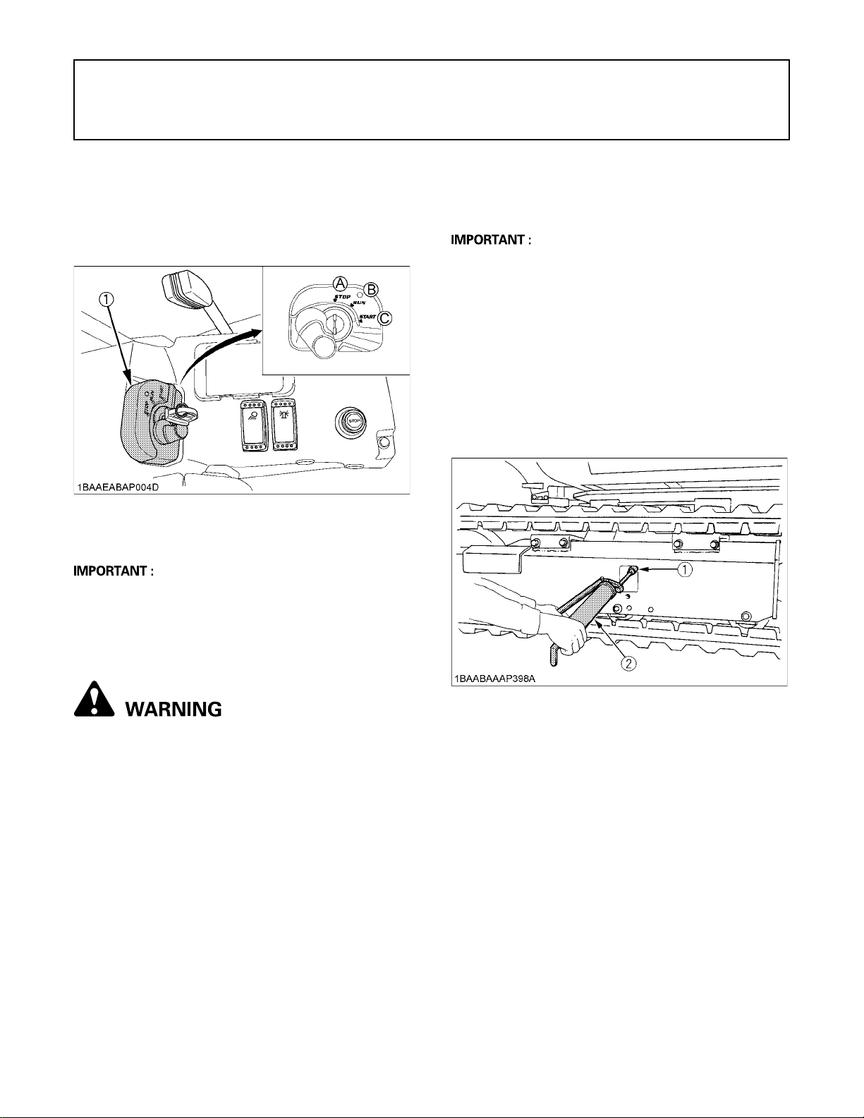
62 OTHER ADJUSTMENTS AND REPLACEMENTS
OTHER ADJUSTMENTS AND REPLACEMENTS
PURGING OF THE FUEL SYSTEM
1. Fill up the fuel tank with fuel.
2. Turn the starter key to the position "RUN".
3. The air in the fuel system will automatically be purged
within one minute.
(1) Starter switch (A) "STOP"
(B) "RUN"
(C) "START"
After adjustment is completed:
Using the socket wrench, tighten the grease fitting.
Tightening torque must be between 98 to 108 N-m.
A If the tracks are too tight, wear is increased.
A If the tracks are too loose, the track pads may collide
with the sprocket and wear is increased.
The track may dislocate or come off.
A Clean the track after every use.
A Should the track tension be high due to sticking mud,
lift the track with the help of the boom, arm and bucket,
idle the engine and remove mud from the track by
rotating it.
C Tension the tracks as specified:
1. Apply grease (2) to the grease fitting (1).
A If the purging was insufficient, the engine stops right
after starting. In this case repeat steps 2 to 3 again.
ADJUSTMENT OF TRACKS
C To loosen the tracks, follow the following
procedure:
To avoid personal injury or death:
A Do not loosen the grease fitting completely or
too quickly. Otherwise grease under high
pressure in the tension cylinder could squirt
out.
A Do not crawl under the excavator.
1. Using a socket wrench, loosen the grease fitting a few
turns.
2. When grease oozes out from the thread, rotate the
track and loosen the track in the lifted position (see
illustration).
(1) Grease fitting
(2) Grease gun
2. Rubber Tracks
Tension the track in the lifted position, so that the
distance "A" (clearance between the track roller and
the inside surface of the track) see illustration, in this
case, the track seam is positioned on the top center
between the idler and the sprocket.
Page 85
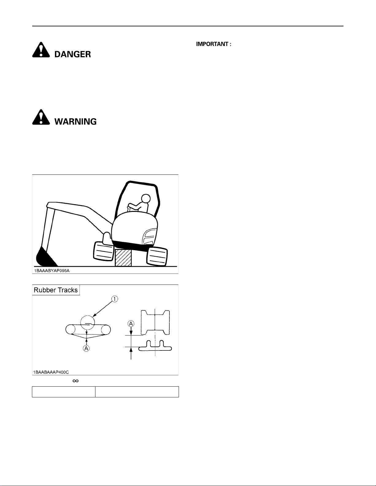
To avoid serious injury or death:
A Do not work under the machine in this
condition.
A For your safety do not rely on hydraulically
supported devices, they may leak down and
suddenly drop or be accidentally lowered.
To avoid personal injury or death:
A When lifting the machine itself with an
attachment, place a safety block or safety post
to prevent the machine from turning over. Keep
the pilot control lock lever in the "LOCKED"
position.
63OTHER ADJUSTMENTS AND REPLACEMENTS
A Make sure that no obstacles, such as stones are
caught in the track. Remove such obstacles before
adjusting the track tension.
A Track seam
The ends of the rubber track are joined with a seam.
When adjusting the tracks, the seam must be
positioned on the top center between the idler and the
sprocket.
If the seam is positioned incorrectly, the tracks will be
tensioned too loosely, and a further readjustment will
be necessary.
A Rotate the track after adjustment one to two times to
check the tension.
A Additionally following points are to be observed when
adjusting rubber tracks.
(1) If the track loosen more than 25 mm (1.0 in.),
readjust them.
(2) Check track tension 50 hours after initial use and
readjust if necessary. Check and adjust thereafter
every 50 service hours.
(1) Seam (Mark " ")
(A) 10 to 15 mm (0.4 to 0.6 in.)
BSpecial Information when Using Rubber
Tracks
1. When turning, make a slow swing turn. Avoid spin
turns to reduce lug wear and entry of dirt.
2. The relief valve may be activated if too much dirt and
sand clog the tracks. In this case move the machine for
a short distance straight backwards to let the earth and
sand fall off, then a turn can be made.
3. Avoid using rubber track on riverbeds, stony
underground, ferro-concrete and on iron plates. The
rubber can damage as well as increase wear on the
tracks.
Page 86
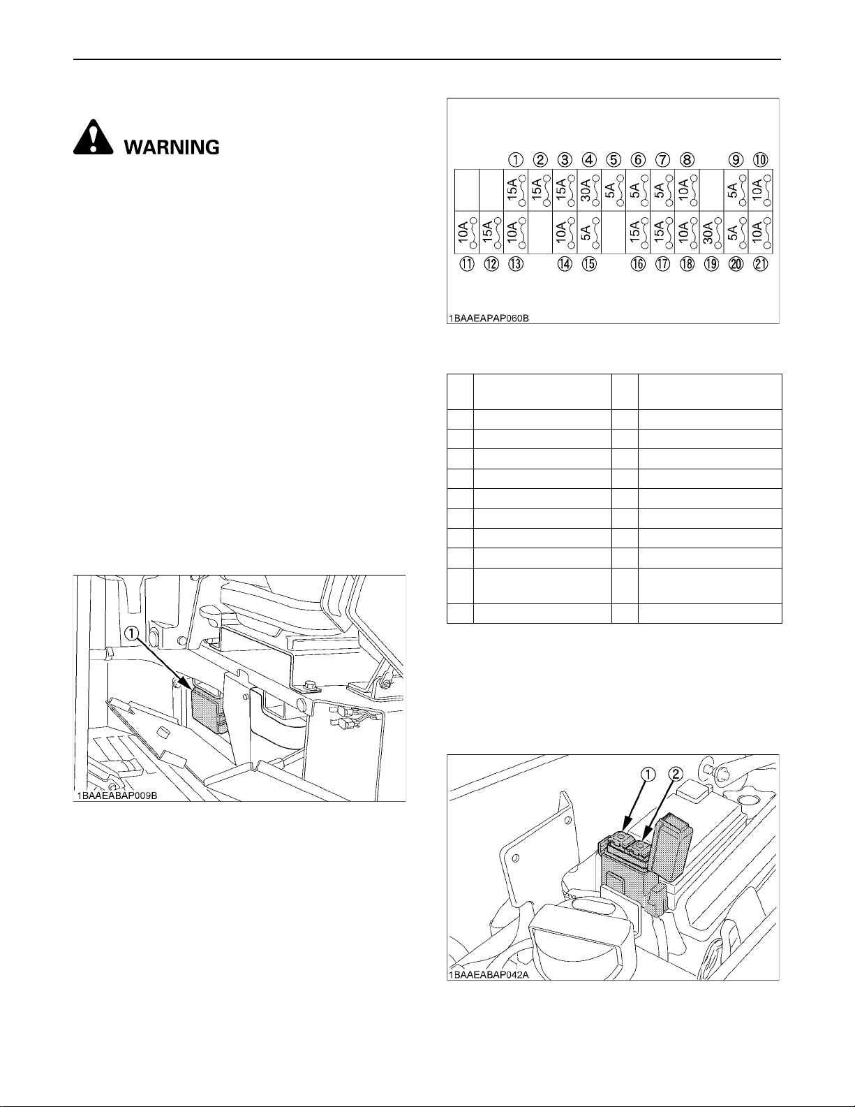
OTHER ADJUSTMENTS AND REPLACEMENTS64
CHANGING THE BUCKET
To avoid personal injury or death:
A When the coupling pins are removed or
installed, chips may come off. Always use
gloves, goggles and a helmet.
A When the change of the equipment must be
performed with the engine running, always
work as a 2-person team.
One person sits in the operator's seat and the
other works on the machine.
A Do not use your fingers to center the holes,
since they may be injured or even cut in case of
sudden or uncontrolled movements.
A Read the manual of the attachment to do a
correct operation safely when other
attachments are installed instead of KUBOTA
specified bucket.
FUSES
BReplacing Fuses
1. Remove the cover of the fuse box.
2. Replace the burnt out fuse with a fuse having the same
capacity.
BFuse Capacities and Circuits
(1) Fuse box
Wiper / washer
1
system
2 Radio (AC) 13 Electrical connection 2
3 12-V socket 14 Control unit (+B)
4 Starter 15 Interior lighting
5 Starter (signal) 16 Rotary beacon
6 Fuel pump 17 Working lights
7 Relay supply circuit 18 Horn
8 Control unit (AC) 19 Engine cut-off switch
9 Control lever lock 20 Horn switch
10 Alternator 21
11 Fan motor
12 Electrical connection
Display and
control unit (+B)
(1) Fuse box
BSlow Blow Fuse
Slow blow fuse is provided to protect the electrical circuits.
If the slow blow fuse is blown, check the electrical circuits
for trouble and then replace with a new compatible slow
blow fuse.
(1) Slow blow fuse (50A)
(2) Slow blow fuse (60A)
Page 87

65TROUBLESHOOTING
TROUBLESHOOTING
If the excavator dose not show the desired performance, or when trouble arises, refer to the table below and undertake
appropriate measures.
Trouble Cause Countermeasure
*Check fuel tank and filter
*Remove impurities and water
*If necessary, replace filter
*Remove water from the fuel tank
*Check fuel pipe joint bolts and nuts for looseness
*Purging of the fuel system (for fuel filter and injection
pump, see "PURGING OF THE FUEL SYSTEM" in "OTHER
ADJUSTMENTS AND REPLACEMENTS".)
*Pour hot water over the radiator
*Recharge battery
*Check fuel and add if necessary
*Clean the air filter element
*Check fuel and add if necessary
*Purge the fuel system
*Use high quality fuel
*Drain engine oil to prescribed oil level
*Adjust or replace
*Fill to prescribed level
*Clean
*Replace coolant fluid and add anti-rust
*Replace
*Clean
*Reduce load
*Fill to prescribed level
*Use prescribed fuel
*Add oil
*Replace hose or joint
*Bring pilot control lock lever into "UNLOCK" position
*Remove
*Adjust accordingly
*Bring pilot control lock lever into "UNLOCK" position
Engine
Hydraulic
System
Drive
System
Starting difficulties
Insufficient engine
power
Engine suddenly
stops
Abnormal exhaust
gas color
Water temperature
too high
(Overheating)
Boom, arm, bucket,
drive, swing and
dozer power is too
low
Swing motor and
front attachment
does not work
Deviation of drive
direction
Drive lever does
not move
Fuel is too viscous
Air or water in the fuel
system
Oil viscosity is too high the
engine runs sluggishly in
winter
Battery is almost dead;
insufficient compression
Low fuel level
Clogged air cleaner
Low fuel level
Poor fuel
Too much engine oil
Worn or torn fan belt
Coolant level too low
Radiator grill or fins are
clogged
Coolant is contaminated
with rust from the cylinder
head or crank case
Defective radiator cap
(Evaporation)
Corroded coolant pipes
Continuous operation
under full load
Engine oil level too low
Use of poor fuel
Hydraulic oil level too low
Leakages of hoses and /
or joints
Pilot control lock lever in
"LOCKED" position
Blocked through stones
Track too loose or too
tight
Pilot control lock lever in
"LOCKED" position
Page 88
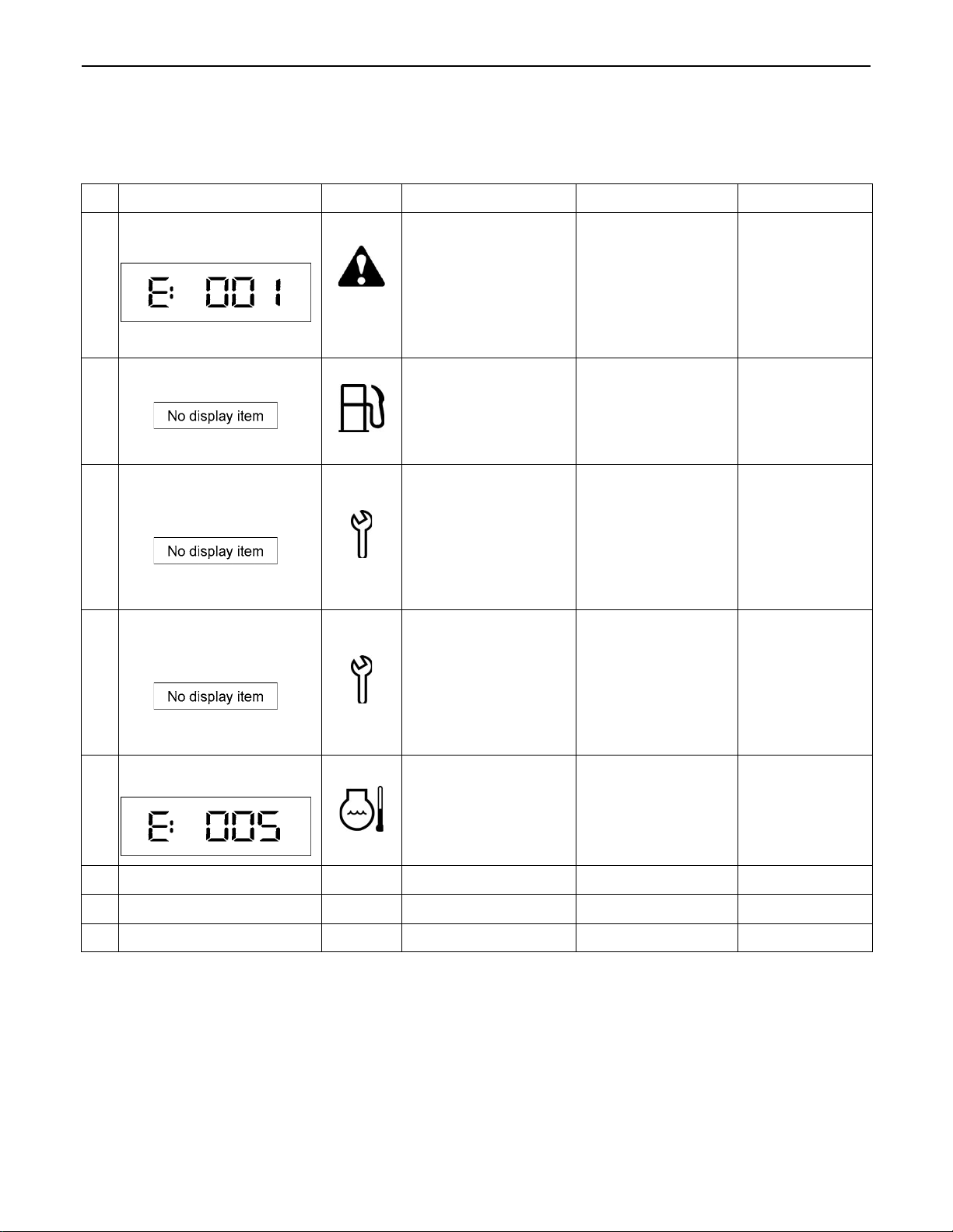
66 TROUBLESHOOTING
KUBOTA I.C.S. NAVIGATION LIST OF MESSAGES
If an error occurs with the machine, one of the following messages appears in the LCD.
In case of a trouble, immediately contact your local dealer for inspection and repair.
LCD
CAN system error
1
Feed fuel
2
LED Problem / Error Preliminary Measure Solution
The Controller Area
(red)
Network (CAN) has
developed a fault.
Measured values may
be incorrect and
switches may not
The machine can be
started and driven.
Do not perform any
work with the
machine.
function.
This message
appears when the fuel
level is low and
--prompts the operator
to refuel.
Inform your
KUBOTA dealer
immediately.
Refuel the
excavator.
Periodic check soon
3
(notice)
Periodic check passed
4
(warning)
Warning temperature
rising
5
6
7
This message
appears 10 hours
before the periodic
check interval.
This message means
that the regular
service is due shortly.
Operate the
machine as usual.
Ask your
KUBOTA dealer
about the
relevant parts.
Run the
maintenance
procedure.
Ask your
KUBOTA dealer
about the
relevant parts.
Run the
maintenance
This message means
that the regular
service is due.
The machine can be
operated but service
must be carried out
urgently.
procedure.
Operate the
The temperature of
the coolant is higher
than normal.
machine only with
reduced loads until
the temperature is
---
normal again.
--- --- --- --- ---
--- --- --- --- ---
8
--- --- --- --- ---
Page 89
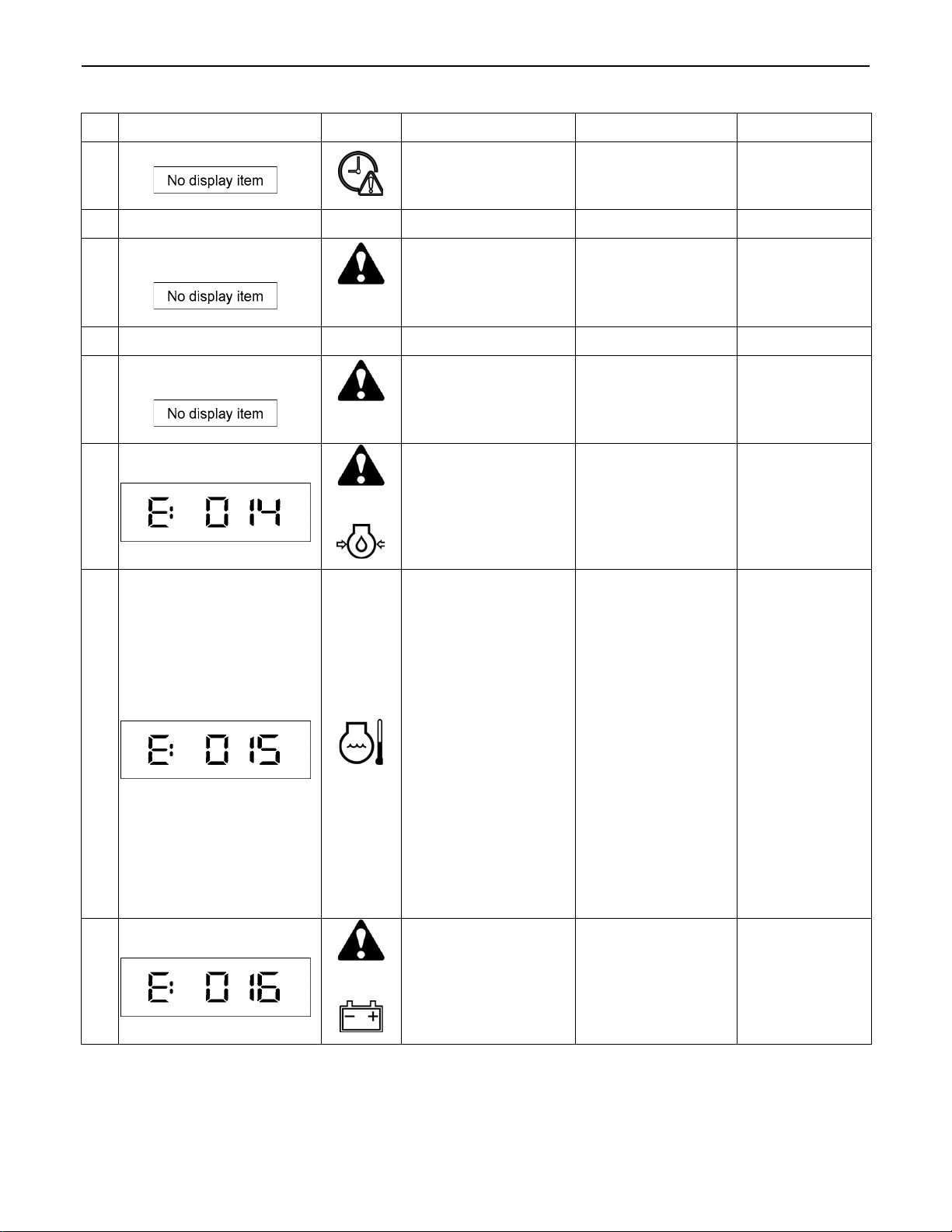
67TROUBLESHOOTING
10
11
12
13
14
LCD
Clock setting request
9
--- --- --- --- ---
Raise the control lever
lock
--- --- --- --- ---
Lower the control lever
lock
Oil pressure too low
LED Problem / Error Solution #1 Solution #2
Power was interrupted
and the clock now has
to be set again.
This message
indicates a step in a
(yellow)
procedure.
This message
indicates a step in a
(yellow)
procedure.
(red)+The engine oil
pressure is too low.
In order to set the
clock, press the user
setting switch.
Raise the pilot
control lock lever;
the indicator goes
out.
Lower the pilot
control lock lever;
the indicator goes
out.
Stop the engine
immediately. The
engine may have
developed a fault.
---
---
---
Inform your
KUBOTA dealer
immediately.
Overheat
15
Charging system error
16
The machine is
overheated and must
cool off by idling.
(red)+The charging system
has developed a fault.
Allow the machine to
cool off by idling. Do
not switch the
engine off as the
coolant could then
boil over.
Check the V-belt.
When the V-belt is
OK, let the engine
run until the indicator
goes out.
Clean the radiator
and check the
coolant. Refill the
radiator with
coolant by its
boiled-over
amount. Unclog
the radiator and
other components
before use again.
Check also the
hydraulic system
for oil leak and
other troubles.
If an oil leak is
found,
immediately
contact your local
dealer for repair.
If the indicator
does not go out,
inform your
KUBOTA dealer
immediately.
Page 90
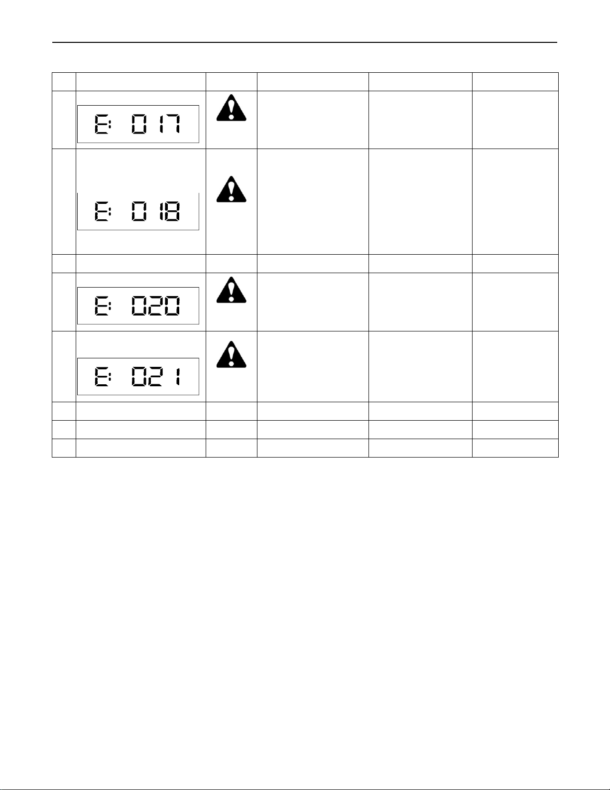
68 TROUBLESHOOTING
LCD LED Problem / Error Solution #1 Solution #2
Fuel sensor error
17
Water temperature sensor
error
18
19
--- --- --- --- ---
Lever lock system error
20
Travel 2 speed system
error
21
(red)
(red)
(red)
(red)
The fuel sensor has
developed a fault; the
fuel gauge does not
appear in the display.
The coolant
temperature sensor
has developed a fault;
the coolant
temperature gauge
does not appear in the
display.
The electrical system
in the pilot control lock
lever has developed a
fault.
The electrical system
in the travel speed has
developed a fault.
Press the display
selector switch to
return to the default
display.
Press the display
selector switch to
return to the default
display. The
functions of the
machine are stable
but overheating
cannot be excluded.
The engine can be
started but the
machine cannot be
set in motion.
The machine can
only be set in motion
at low speed.
Inform your
KUBOTA dealer
immediately.
Inform your
KUBOTA dealer
immediately.
Inform your
KUBOTA dealer
immediately.
Inform your
KUBOTA dealer
immediately.
22
23
24
--- --- --- --- ---
--- --- --- --- ---
--- --- --- --- ---
Page 91
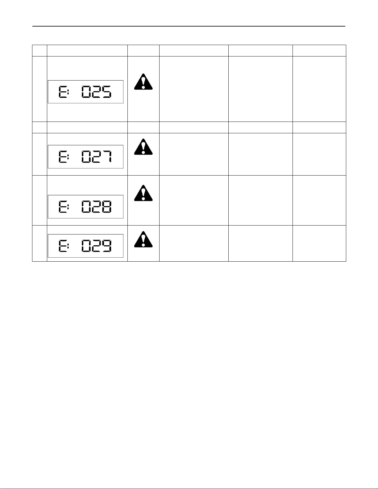
25
LCD LED Problem / Error Solution #1 Solution #2
This is a warning that a
Overvoltage
(red)
higher voltage (from a
24-V battery, for
example) is being
applied to the electric
circuit, or that there is
a problem with the
Switch the engine off
immediately and
check the battery
and the alternator.
Restart the engine.
If the indicator
lights up again
after restarting,
inform your
KUBOTA dealer
immediately.
alternator.
69TROUBLESHOOTING
26
--- --- --- --- ---
External 5-V system error
27
External 12-V system
error
28
Starting the engine
29
(red)
(red)
(yellow)
The 5-V sensor supply
line has developed a
system fault. The main
functions are not
available.
The 12-V sensor
supply line has
developed a system
fault. The main
functions are not
available.
This message
indicates a step in a
procedure.
The machine can be
started and driven.
Do not perform any
work with the
machine.
The machine can be
started and driven.
Do not perform any
work with the
machine.
Start the engine; the
indicator goes out.
Inform your
KUBOTA dealer
immediately.
Inform your
KUBOTA dealer
immediately.
---
Page 92
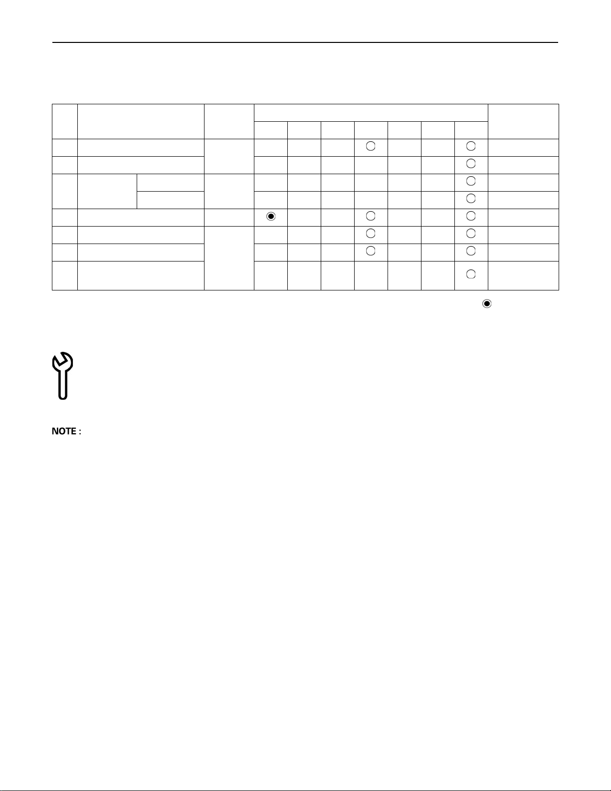
70 TROUBLESHOOTING
C Service hour meter
When the hour meter has counted up to the hours circled in the maintenance list below, the message appears. The
message shows up as follows.
No. Check points Measures
50 100 250 500 600 750 1000
Hour meter indicator
Interval
1 Engine oil
2 Hydraulic oil every 1000 hrs
Air filter
3
element
4 Drive unit oil change every 500 hrs
5 Engine oil filter
6 Hydraulic return element every 500 hrs
7
The indicator "Maintenance" shines when a service period is due.
(The message reappears on the hour meter designated next.)
Hydraulic suction filter
Outer element
Inner element every 1000 hrs
element
change
replace
replace
every 500 hrs
every 1000 hrs
every 500 hrs
every 1000 hrs
First operation
A The maintenance indicator disappears automatically in about 10 seconds.
A When the key is turned from "STOP" to "RUN", the maintenance indicator reappears and disappears again
automatically in about 10 seconds.
A When the key is turned from "STOP" to "RUN" repeatedly 10 times, the indicator disappears.
C In case the service hour meter replaced due to any trouble with it, the meter is set to "0". Contact your KUBOTA dealer
for details.
Page 93

71OPERATION UNDER COLD WEATHER CONDITIONS
OPERATION UNDER COLD WEATHER CONDITIONS
PREPARATION FOR OPERATION IN COLD WEATHER
1. Replace engine oil and hydraulic oil with those of
viscosities suitable for cold weather.
2. In cold weather, battery power drops, and the battery
fluid may freeze if the battery is not sufficiently
charged. To prevent the battery fluid from freezing, be
sure to keep the battery charged at least 75% or more
of its capacity after operation. To ease next starting, it
is recommended to keep the battery stored in closed
or heated rooms. If the battery fluid level is too low, do
not add after operation, but add with the engine
running before the next operation.
3. Add anti-freeze to coolant in the radiator and recovery
tank, if the ambient temperature is expected to drop
below 0 (32 ). Mixing ratio of water and anti-freeze
is 50%/50%.
A Use permanent anti-freeze or long-life coolant.
A Drain the coolant completely and clean the radiator
inside then fill with the water and anti-freeze mixture.
A As the anti-freeze also acts as an anti-corrosive, it is
not necessary to add an additive to the water and antifreeze mixture.
A See "Checking Coolant Level" under "DAILY
CHECKS" in "MAINTENANCE" for radiator fill
volumes.
PROCEDURE AFTER COMPLETING WORK
Clean the excavator thoroughly after work and wipe dry.
Otherwise mud and earth on the tracks could freeze if the
temperature drops below the 0 (32 ) mark. Operation
of the excavator is then not possible. Store the excavator
in a dry place; if not possible, store on wooden planks or
on mats. If the excavator is kept on damp or muddy
ground, the tracks could freeze overnight. Operation of
the excavator is then not possible. Furthermore the drive
unit may be damaged.
Additionally, the piston rods of the hydraulic cylinders
must be rubbed dry. Otherwise severe damage could
occur if dirty water seeps through the seals.
Page 94

72 LONG STORAGE
LONG STORAGE
To avoid personal injury or death:
A Do not clean the excavator with the engine running.
A To avoid the danger of exhaust fume poisoning, do not operate the engine in a closed building without
proper ventilation.
A When storing, remove the key from the starter switch to avoid unauthorized persons from operating the
excavator and getting injured.
A Bring the excavator on a firm, flat, and level surface. Lower the attachments and dozer blade on the ground.
B Should the Excavator be Stored for a Longer Period of Time, Observe Following Procedures:
1. The whole excavator should be cleaned thoroughly and in all cases stored indoors. If the excavator has to be kept
outdoors, Iay out wooden planks on an even ground, place the excavator on the planks and cover completely.
2. Do an oil change and grease the excavator.
3. Heavily grease the visible section of the piston rods.
4. Remove the battery and store indoors.
5. If it is expected that the temperature will sink below the 0 (32 ) mark, add anti-freeze or drain coolant completely.
A Wash the excavator after stopping the engine.
If you wash the excavator while running the engine, splashing water gets into the air cleaner through its intake and
cause engine damage.
Careful, wash and do not splash water over the air cleaner while the engine is running.
B Observe Following Procedures when the Machine is to be Operated after Long Storage.
1. Wipe off the grease from the hydraulic cylinder rods.
2. Turn on the engine and operate the attachments and the drive mechanisms under no load in order to circulate the
hydraulic oil.
(If the machine is stored for longer than one month, do steps 1 and 2 once every month.)
Page 95
73LONG STORAGE
Periodic replacement of important component parts
To ensure safety in operation, you are strongly requested to inspect and service the machine at regular intervals. For added
safety, ask your KUBOTA dealer to replace the following important component parts periodically.
These parts are prone to degradation in material or subject to wear and tear with time. It is difficult to judge how much they
have been affected at regular inspection. It is therefore necessary to replace them with new ones after a specified time of
use, whether wear is visible or not.
If any of them is found to be worn before the specified use, they must be repaired or replaced the same as other parts.
If any of the hose clamps are found deformed or cracked, the hose clamps must also be replaced.
For the hydraulic hoses other than the ones to be replaced periodically, inspect them for the following points. If found loose
or very worn, tighten and / or replace the hose.
When replacing the hydraulic hoses, change their O rings and sealing components with new ones.
For replacement of the important parts, contact your KUBOTA dealer.
A At the following periodic inspections, check the fuel hoses and hydraulic hoses as well.
Inspection Interval Check points
Daily Checks Oil leak at fuel and hydraulic hose connections and points
Every month
Every year
Oil leak at fuel and hydraulic hose connections and points
Damages at fuel and hydraulic hose (cracks, chafing)
Oil leak at fuel and hydraulic hose connections and points
Interference, deformation, degradation, twist and other damages (cracks, chafing) of fuel and hydraulic
hoses
List of important component parts
No. Component parts Used place Q'ty Period
Fuel tank - Water separator 1
Water separator - Fuel pump 1
1 Fuel hose
2 Hydraulic hose (suction) Tank - Main pump 1
3 Hydraulic hose (delivery)
4 Hydraulic hose (Boom cylinder) Control valve - Boom cylinder *2
5 Hydraulic hose (Arm cylinder)
6 Hydraulic hose (Bucket cylinder)
7 Hydraulic hose (Swing cylinder) Control valve - Swing cylinder 2
8 Hydraulic hose (Dozer cylinder)
9 Hydraulic hose (Service port)
10 Hydraulic hose (Swivel motor) Control valve - Swivel motor 2
Fuel pump - Fuel filter 1
Fuel filter - Fuel nozzle 2
Fuel nozzle - Fuel tank 2
Main pump - Control valve 3
Main pump - Pilot filter 1
Pilot filter - Change valve 2
Control valve - Hose joint *2
Hose joint - Arm cylinder *2
Control valve - Hose joint *2
Hose joint - Bucket cylinder *2
Control valve - Rotary joint 2
Rotary joint - Adapter 2
Adapter - Dozer cylinder 2
Control valve - Hose joint 2
Hose joint - Adapter 2
Every 2 years or
4000 hours
To prevent serious damage to the hydraulic system, use only a KUBOTA genuine hydraulic hose.
Page 96

74 RECOMMENDED OILS
RECOMMENDED OILS
A Other than the oil mentioned below, JCMAS HK certified oil and GK certified grease can also be used. Check the Japan
Lubricating Oil Society (JALOS) website for more details.
Recommendation Filled at the factory
Engine oil
Coolant
Grease
Hydraulic oil
Gear oil
Diesel
Ambient
temperature
conditions
In winter and/or at
low temperatures
In summer and/or
at high ambient
temperatures
All-weather 15W-40* Shell Rimula R4L* 15W40, API CI-4
In winter and/or at
low temperatures
In summer and/or
at high ambient
temperatures
In winter and/or at
low temperatures
In summer and/or
at high ambient
temperatures
All-weather 80W-90* Shell
Viscosity
SAE 10W
SAE 20W
SAE 30
SAE 40
SAE 50
NLGI-2*
NLGI-1 WEICON
ISO 32
ISO 46*
ISO 46
ISO 68
SAE 75
SAE 80
SAE 90
SAE 140
Quality
standard
API CI-4
G048*
SAE J1034*
MB 325.0*
ASTM D3306*
D4985
DIN 51825
KP2K-30*
MIL-L-2105C*
EN 590
ASTM D975
Brand Type
Hightec
ROWE
Mobil Mobilux EP2*
Shell
Antifreeze AN
(-37 )*
Antiseize
Standard
Tellus
S2M46*
Spirax
MA80W*
When diesel fuel with a high sulphur
content (between 0.50 % and 1.00 %) is
used, the engine oil and engine oil filter
must be replaced at shorter intervals.
Never use diesel fuel with a sulphur
content exceeding 1.00 %.
Always use distilled water to mix with
antifreeze.
Always follow the recommendations of
the coolant manufacturer for the mixing
ratio. Do not mix with other coolants.
Only use during the first 50 working
hours (on all greasing points around the
swing block).
The fuel filled at the factory is not winter
diesel. For preparing the excavator for
use in winter, fill the fuel tank with winter
diesel and allow the engine to run for a
few minutes.
Note
Refrigerant HFC R134a
* This lubricant is filled while manufacturing the engine.
Never use diesel fuel with a sulphur
content exceeding 1.00 %.
Page 97
C Engine Oil:
A Oil used in the engine should have an American Petroleum Institute (API) service classification and Proper SAE
Engine Oil according to the ambient temperatures.
Above 25 (77 ) SAE 30 or SAE 10W-30, SAE 15W-40
0 to 25 (32 to 77 ) SAE 20 or SAE 10W-30, SAE 15W-40
Below 0 (32 ) SAE 10W or SAE 10W-30, SAE 15W-40
A Refer to the following table for the suitable API classification engine oil according to the engine type (with internal
EGR, external EGR or non-EGR) and the fuel.
75RECOMMENDED OILS
Fuel used
Ultra Low Sulfur Fuel
[<0.0015% (15 ppm)]
EGR: Exhaust Gas Re-circulation
A The CJ-4 engine oil is intended for DPF (Diesel Particulate Filter) type engines, and cannot be used on this
machine.
Model U27-4 ---
C Fuel:
A Cetane number of 45 is minimum. Cetane number greater than 50 is preferred, especially for temperatures below
-20 (-4 ) or elevations above 1500 m (5000 ft).
A Diesel fuels specified to EN 590 or ASTM D975 are recommended.
A No.2-D is a distillate fuel of lower volatility for engines in industrial and heavy mobile service. (SAE J313 JUN87)
Oil class of engines except external EGR Oil class of engines with external EGR
CG-4, CH-4 or CI-4
except external EGR with external EGR
Engine oil classification (API classification)
CI-4
(Class CG-4 and CH-4 engine oils cannot be
used on EGR type engines)
Page 98
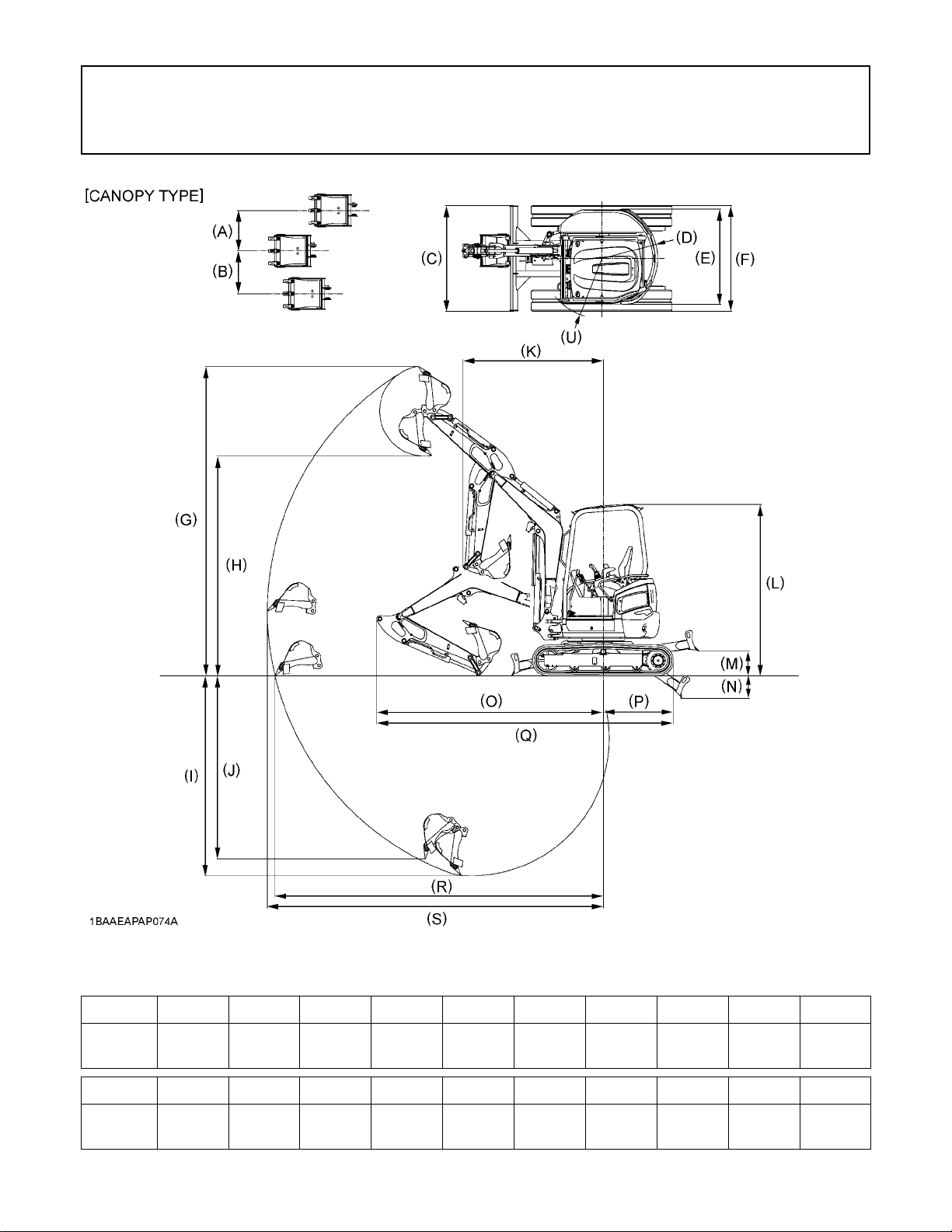
76 MAIN DIMENSIONS
MAIN DIMENSIONS
U27-4
CANOPY
U27-4
CANOPY
mm (in.)
(A) (B) (C) (D) (E) (F) (G) (H) (I) (J)
580
(22.8)
(K) (L) (M) (N) (O) (P) (Q) (R) (S) (U)
1980
(78.0)
610
(24.0)
2420
(95.3)
1500
(59.1)
350
(13.8)
790
(31.1)
320
(12.6)
1350
(53.1)
3200
(126.0)
1500
(59.1)
990
(39.0)
4370
(172.0)
4190
(165.0)
3100
(122.0)
4630
(182.3)
2820
(111.0)
4740
(186.6)
(101.6)
2580
850
(33.5)
Page 99
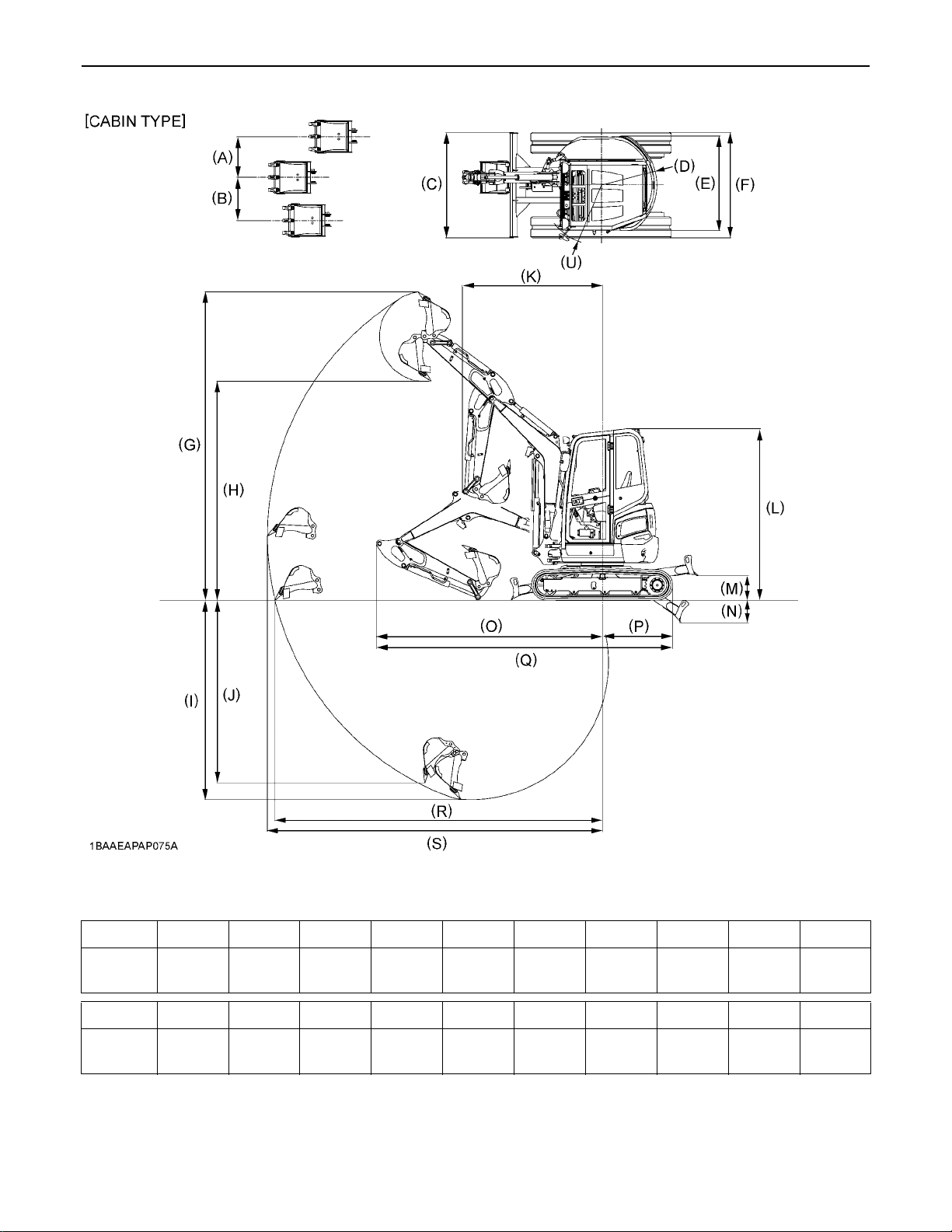
77MAIN DIMENSIONS
U27-4
CABIN
U27-4
CABIN
mm (in.)
(A) (B) (C) (D) (E) (F) (G) (H) (I) (J)
580
(22.8)
(K) (L) (M) (N) (O) (P) (Q) (R) (S) (U)
1980
(78.0)
610
(24.0)
2430
(95.7)
1500
(59.1)
350
(13.8)
790
(31.1)
320
(12.6)
1350
(53.1)
3200
(126.0)
1500
(59.1)
990
(39.0)
4370
(172.0)
4190
(165.0)
3100
(122.0)
4630
(182.3)
2820
(111.0)
4740
(186.6)
(101.6)
2580
870
(34.3)
Page 100
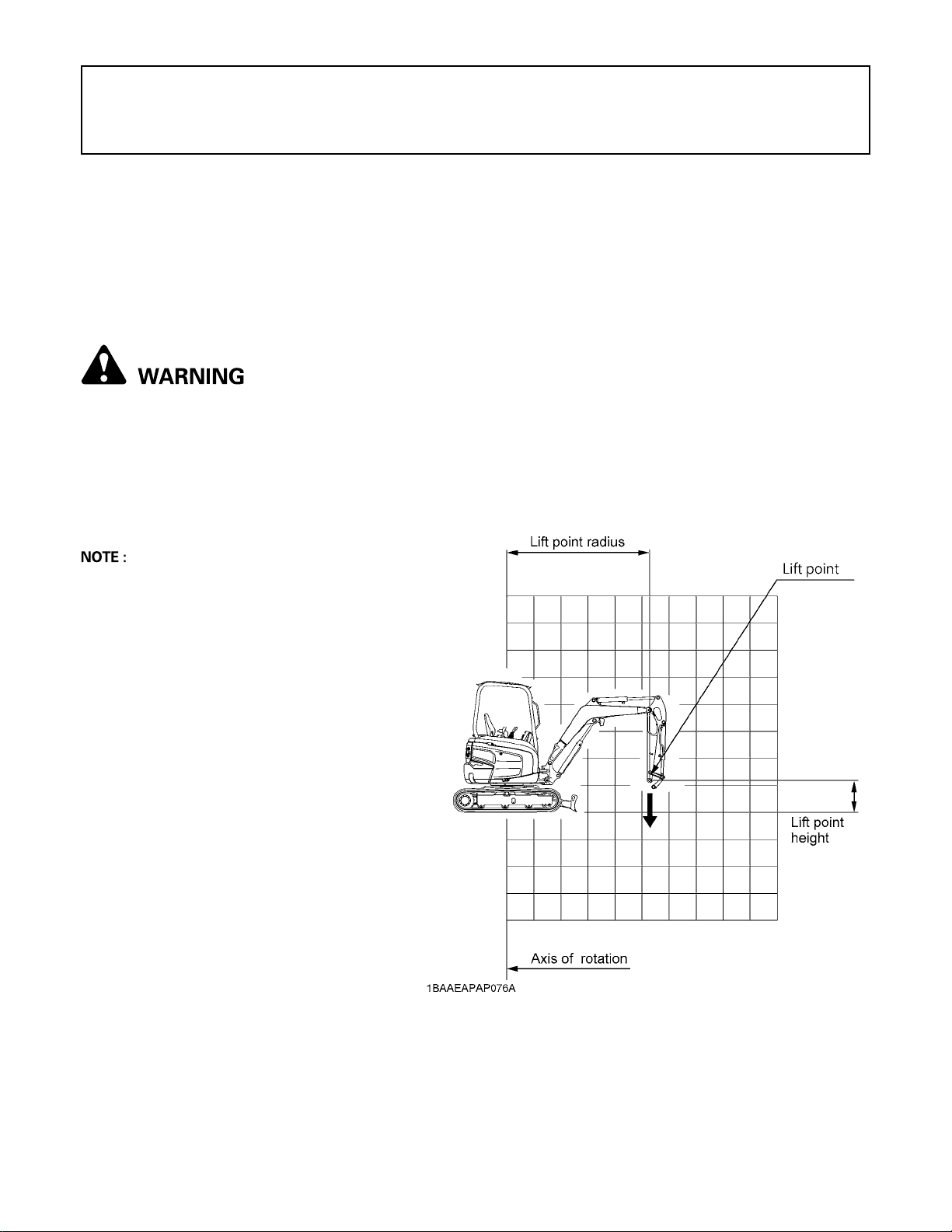
78 LIFTING CAPACITY
LIFTING CAPACITY
1. The lifting capacities are based on ISO 10567 and do not exceed 75% of the static tilt load of the machine or 87% of
the hydraulic lifting capacity of the machine.
2. The strokes are as follows.
(1) The load point corresponds to the front bolt part of the arm.
(2) The machine positions are over - front (Blade down).
(3) The operating cylinder is the boom cylinder.
3. The bucket of the excavator, the hook, the sling and other lifting accessories are taken into consideration for the loads.
Machine conditions:
No bucket, all others according to the standard regulations.
To avoid personal injury or death:
A No loads greater than those values mentioned in the lifting capacity tables are to be lifted.
A No loads greater than 1 ton are to be lifted when no safety devices are attached to boom and dozer blade
cylinders.
A The values mentioned in the table are valid only on even, hard grounds. When lifting on soft ground, the
machine can tip over due to the load being concentrated only on one side of the machine.
A The table values are calculated at the end of the arm without the bucket. In order to find the allowable loads
for machines with bucket, the bucket weight must be subtracted from the values in the table.
A In this manual, the machine's lifting capacity is
discussed, but it does not mean that it is
recommended to use the machine for lifting jobs.
A It is specified in Item 3.4 of ISO 10567:1992 that
the following devices must be additionally
installed if a hydraulic excavator with the rated
lift load of over 1,000 kg at its minimum lifting
radius or the tilting moment of over 40,000 N-m
is used for lifting loads.
(1) Lifting hook
(2) Acoustic alarm or warning lamp for the
operator when the rated load or the
corresponding tilting moment has been
exceeded.
(3) Boom descending control device
conforming to ISO 8643:1997
 Loading...