


WORKSHOP MANUAL
DIESEL ENGINE
05-E2B SERIES,
05-E2BG SERIES
KiSC issued 06, 2011 A
TO THE READER
This Workshop Manual has been prepared to provide servicing personnel with information on the mechanism, service and maintenance of 05-E2B and 05-E2BG series. It is divided into three parts, “General”, “Mechanism” and “Servicing”.
Q General
Information on the engine identification, the general precautions, maintenance check list, check and maintenance and special tools are described.
QMechanism
Information on the construction and function are included. This part should be
understood before proceeding with troubleshooting, disassembling and servicing. Refer to Diesel Engine Mechanism Workshop Manual (Code No. 9Y021-01870) for
the one which has not been described to this workshop manual.
QServicing
Information on the troubleshooting, servicing specification lists, tightening torque,
checking and adjusting, disassembling and assembling, and servicing which cover procedures, precautions, factory specifications and allowable limits.
All information illustrations and specifications contained in this manual are based on the latest product information available at the time of publication.
The right is reserved to make changes in all information at any time without notice. Do to covering many models of this manual, information or picture being used have
not been specified as one model.
August 2005
© KUBOTA Corporation 2005
KiSC issued 06, 2011 A

05-E2B, 05-E2BG, WSM |
SAFETY INSTRUCTIONS |
SAFETY FIRST
This symbol, the industry’s “Safety Alert Symbol”, is used throughout this manual and on labels on the machine itself to warn of the possibility of personal injury. Read these instructions carefully.
It is essential that you read the instructions and safety regulations before you attempt to repair or use this unit.
|
DANGER |
: Indicates an imminently hazardous situation which, if not avoided, will result in |
|
|
|
death or serious injury. |
|
|
|
|
|
|
|
|
|
|
WARNING |
: Indicates a potentially hazardous situation which, if not avoided, could result in |
|
|
|
death or serious injury. |
|
|
|
|
|
|
|
|
|
|
CAUTION |
: Indicates a potentially hazardous situation which, if not avoided, may result in |
|
|
|
minor or moderate injury. |
|
|
|
|
|
|
|
|
|
|
Q IMPORTANT |
: Indicates that equipment or property damage could result if instructions are not |
|
|
|
followed. |
|
|
|
|
|
|
|
|
|
|
Q NOTE |
: Gives helpful information. |
|
|
|
|
|
|
|
|
BEFORE SERVICING AND REPAIRING |
|
|
|
|
|
|
|
• Read all instructions and safety instructions in this |
|
|
|
manual and on your engine safety decals. |
|
|
|
• Clean the work area and engine. |
|
|
|
• Park the machine on a firm and level ground. |
|
|
|
• Allow the engine to cool before proceeding. |
|
|
|
• Stop the engine, and remove the key. |
|
|
|
• Disconnect the battery negative cable. |
|
|
|
• Hang a “DO NOT OPERATE” tag in operator |
|
|
|
station. |
|
|
|
|
1 |
KiSC issued 06, 2011 A |
|

05-E2B, 05-E2BG, WSM
SAFETY INSTRUCTIONS
SAFETY STARTING
•Do not start the engine by shorting across starter terminals or bypassing the safety start switch.
•Unauthorized modifications to the engine may impair the function and / or safety and affect engine life.
SAFETY WORKING
•Do not work on the machine while under the influence of alcohol, medication, or other substances or while fatigued.
•Wear close fitting clothing and safety equipment appropriate to the job.
•Use tools appropriate to the work. Makeshift tools, parts, and procedures are not recommended.
•When servicing is performed together by two or more persons, take care to perform all work safely.
•Do not touch the rotating or hot parts while the engine is running.
•Never remove the radiator cap while the engine is running, or immediately after stopping. Otherwise, hot water will spout out from radiator. Only remove radiator cap when cool enough to touch with bare hands. Slowly loosen the cap to first stop to relieve pressure before removing completely.
•Escaping fluid (fuel or hydraulic oil) under pressure can penetrate the skin causing serious injury. Relieve pressure before disconnecting hydraulic or fuel lines. Tighten all connections before applying pressure.
•Wear a suitable hearing protective device such as earmuffs or earplugs to protect against objectionable or uncomfortable loud noises.
AVOID FIRES
•Fuel is extremely flammable and explosive under certain conditions. Do not smoke or allow flames or sparks in your working area.
•To avoid sparks from an accidental short circuit, always disconnect the battery negative cable first and connect it last.
•Battery gas can explode. Keep sparks and open flame away from the top of battery, especially when charging the battery.
•Make sure that no fuel has been spilled on the engine.
2 |
KiSC issued 06, 2011 A |
|

05-E2B, 05-E2BG, WSM
SAFETY INSTRUCTIONS
VENTILATE WORK AREA
•If the engine must be running to do some work, make sure the area is well ventilated. Never run the engine in a closed area. The exhaust gas contains poisonous carbon monoxide.
DISPOSE OF FLUIDS PROPERLY
•Do not pour fluids into the ground, down a drain, or into a stream, pond, or lake. Observe relevant environmental protection regulations when disposing of oil, fuel, coolant, electrolyte and other harmful waste.
PREVENT ACID BURNS
•Sulfuric acid in battery electrolyte is poisonous. It is strong enough to burn skin, clothing and cause blindness if splashed into eyes. Keep electrolyte away from eyes, hands and clothing. If you spill electrolyte on yourself, flush with water, and get medical attention immediately.
PREPARE FOR EMERGENCIES
•Keep a first aid kit and fire extinguisher handy at all times.
•Keep emergency numbers for doctors, ambulance service, hospital and fire department near your telephone.
3 |
KiSC issued 06, 2011 A |
|

05-E2B, 05-E2BG, WSM SPECIFICATIONS
SPECIFICATIONS
Model |
|
D905-E2B |
|
D1005-E2B |
|
V1305-E2B |
||||||
|
|
|
|
|
|
|
|
|
|
|
|
|
Number of Cylinders |
|
|
|
|
3 |
|
|
|
|
4 |
||
|
|
|
|
|
|
|
|
|||||
Type |
|
|
|
Vertical, Water-cooled, 4 cycle diesel engine |
|
|
||||||
|
|
|
|
|
|
|
|
|
|
|
||
Bore × Stroke |
mm (in.) |
72 × 73.6 |
(2.83 × 2.90) |
|
|
76 × 73.6 (2.99 × 2.90) |
|
|
||||
|
|
|
|
|
|
|
|
|||||
Total Displacement |
cm3 (cu.in.) |
898 (54.80) |
|
1001 (61.08) |
|
1335 (81.46) |
||||||
ISO Net Continuous |
kW/min-1 (rpm) |
13.0 / 3000 |
|
15.2 / 3600 |
|
14.5 / 3000 |
|
16.8 / 3600 |
|
19.0 / 3000 |
|
22.4 / 3600 |
(HP/min-1 (rpm)) |
(17.4 / 3000) |
|
(20.4 / 3600) |
|
(19.5 / 3000) |
|
(22.5 / 3600) |
|
(26.0 / 3000) |
|
(30.0 / 3600) |
|
ISO/SAE Net Intermittent |
14.9 / 3000 |
|
17.5 / 3600 |
|
16.8 / 3000 |
|
19.4 / 3600 |
|
22.4 / 3000 |
|
25.7 / 3600 |
|
kW/min-1 (rpm) (HP/min-1 (rpm)) |
(20.0 / 3000) |
|
(23.5 / 3600) |
|
(22.5 / 3000) |
|
(26.0 / 3600) |
|
(30.0 / 3000) |
|
(34.5 / 3600) |
|
SAE Gross Intermittent |
|
15.5 / 3000 |
|
18.5 / 3600 |
|
17.5 / 3000 |
|
20.4 / 3600 |
|
23.4 / 3000 |
|
27.2 / 3600 |
kW/min-1 (rpm) (HP/min-1 (rpm)) |
(20.8 / 3000) |
|
(24.8 / 3600) |
|
(23.5 / 3000) |
|
(27.3 / 3600) |
|
(31.4 / 3000) |
|
(36.5 / 3600) |
|
Maximum Bare Speed |
(min-1 (rpm)) |
3200 |
|
3800 |
|
3200 |
|
3800 |
|
3200 |
|
3800 |
Minimum Bare Idling Speed |
|
|
|
|
|
900 |
|
|
|
|
||
|
(min-1 (rpm)) |
|
|
|
|
|
|
|
|
|
||
|
|
|
|
|
|
|
|
|
|
|
|
|
Combustion Chamber |
|
|
|
|
|
Spherical type (E-TVCS) |
|
|
|
|||
|
|
|
|
|
|
|
|
|
|
|||
Fuel Injection Pump |
|
|
|
|
|
Bosch MD type mini pump |
|
|
|
|||
|
|
|
|
|
|
|
|
|
|
|||
Governor |
|
|
|
|
|
All speed mechanical governor |
|
|
|
|||
|
|
|
|
|
|
|
||||||
Direction of Rotation |
|
|
|
Counter-clockwise (viewed from flywheel side) |
|
|
||||||
|
|
|
|
|
|
|
|
|
|
|||
Injection Nozzle |
|
|
|
|
|
Mini Nozzle (DNOPD) |
|
|
|
|||
|
|
|
|
|
|
|
|
|
|
|
|
|
|
|
0.31 rad |
|
0.37 rad |
|
0.31 rad |
|
0.37 rad |
|
0.31 rad |
|
0.37 rad |
Injection Timing |
|
(18 °) before |
|
(21 °) before |
|
(18 °) before |
|
(21 °) before |
|
(18 °) before |
|
(21 °) before |
|
|
T.D.C. |
|
T.D.C. |
|
T.D.C. |
|
T.D.C. |
|
T.D.C. |
|
T.D.C. |
|
|
|
|
|
|
|
|
|
|
|
||
Firing Order |
|
|
1-2-3 |
|
|
|
1-3-4-2 |
|||||
|
|
|
|
|
|
|
|
|
|
|||
Injection Pressure |
|
|
|
|
13.73 MPa (140 kgf/cm2, 1991 psi) |
|
|
|
|
|||
Compression Ratio |
|
23 : 1 |
|
|
24 : 1 |
|
|
|||||
|
|
|
|
|
|
|
|
|
|
|
|
|
Lubricating System |
|
|
|
|
Forced lubrication by trochoid pump |
|
|
|
||||
|
|
|
|
|
|
|
|
|
|
|||
Oil Pressure Indicating |
|
|
|
|
|
Electrical type switch |
|
|
|
|||
|
|
|
|
|
|
|
|
|
||||
Lubricating Filter |
|
|
|
|
Full flow paper filter (Cartridge type) |
|
|
|
||||
|
|
|
|
|
|
|
||||||
Cooling System |
|
|
|
Pressurized radiator, forced circulation with water pump |
|
|
||||||
|
|
|
|
|
|
|
|
|
|
|||
Starting System |
|
|
|
|
|
Electric Starting with Starter |
|
|
|
|||
|
|
|
|
|
|
|
|
|
|
|||
Starting Motor |
|
12 V, 0.9 kW |
|
|
|
12 V, 1.0 kW |
|
|
||||
|
|
|
|
|
|
|
|
|
|
|
|
|
Starting Support Device |
|
|
|
|
By glow plug in combustion chamber |
|
|
|
||||
|
|
|
|
|
|
|
|
|
|
|||
Battery |
|
|
|
|
|
12 V, 60 AH, equivalent |
|
|
|
|||
|
|
|
|
|
|
|
|
|
|
|||
Charging Alternator |
|
12 V, 150 W |
|
|
|
12 V, 360 W |
|
|
||||
|
|
|
|
|
|
|
|
|
|
|
|
|
Fuel |
|
|
|
|
|
Diesel Fuel No.2-D (ASTM D975) |
|
|
|
|||
|
|
|
|
|
|
|
||||||
|
|
|
|
Class CF lubricating oil as per API classification is recommended. |
|
|
||||||
Lubricating Oil |
|
If this class of lubricating oil is not available, preferably use Class CD or CE lubricating oil. |
||||||||||
|
|
|
|
For details on recommended lubricating oils, see page G-5, 8. |
|
|
||||||
|
|
|
|
|
|
|
|
|
|
|
|
|
Lubricating Oil Capacity |
|
|
|
5.1 L (1.35 U.S.gals) |
|
|
|
6.0 L (1.59 U.S.gals) |
||||
(Oil Pan Depth 125 mm (4.92 in.)) |
|
|
|
|
|
|||||||
|
|
|
|
|
|
|
|
|
|
|
||
|
|
|
|
|
|
|
|
|||||
Weight (Dry) |
kg (lbs) |
|
93.0 (205.0) |
|
|
|
110.0 (242.5) |
|||||
|
|
|
|
|
|
|
|
|
|
|
|
|
*The specification described above is of the standard engine of each model.
*Conversion Formula : HP = 0.746 kW, PS = 0.7355 kW
W10275180
4 |
KiSC issued 06, 2011 A |
|
05-E2B, 05-E2BG, WSM |
|
|
|
|
|
|
SPECIFICATIONS |
|
|
|
|
|
|
|
|
|
|
Model |
|
D1105-E2B |
|
V1505-E2B |
|
D1105-T-E2B |
V1505-T-E2B |
|
|
|
|
|
|
|
|
|
|
Number of Cylinders |
|
3 |
|
4 |
|
3 |
4 |
|
|
|
|
|
|
|
|
|
|
Type |
|
|
|
Vertical, Water-cooled, 4 cycle diesel engine |
|
|
||
|
|
|
|
|
|
|
|
|
Bore × Stroke |
mm (in.) |
|
|
78 × 78.4 |
(3.07 × 3.09) |
|
|
|
|
|
|
|
|
|
|
|
|
Total Displacement |
cm3 (cu.in.) |
1123 (68.53) |
|
1498 (91.41) |
|
1123 (68.53) |
1498 (91.41) |
|
ISO Net Continuous |
kW/min-1 (rpm) |
16.2 / 3000 |
|
21.7 / 3000 |
|
20.4 / 3000 |
27.2 / 3000 |
|
(HP/min-1 (rpm)) |
(21.7 / 3000) |
|
(29.1 / 3000) |
|
(27.4 / 3000) |
(36.4 / 3000) |
|
|
ISO/SAE Net Intermittent |
18.7 / 3000 |
|
25.0 / 3000 |
|
23.5 / 3000 |
31.3 / 3000 |
|
|
kW/min-1 (rpm) (HP/min-1 (rpm)) |
(25.0 / 3000) |
|
(33.5 / 3000) |
|
(31.5 / 3000) |
(42.0 / 3000) |
|
|
SAE Gross Intermittent |
|
19.4 / 3000 |
|
26.5 / 3000 |
|
24.5 / 3000 |
33.0 / 3000 |
|
kW/min-1 (rpm) (HP/min-1 (rpm)) |
(26.0 / 3000) |
|
(35.5 / 3000) |
|
(32.8 / 3000) |
(44.2 / 3000) |
|
|
Maximum Bare Speed |
(min-1 (rpm)) |
|
|
3200 |
|
|
||
Minimum Bare Idling Speed |
|
|
|
900 |
|
|
||
|
(min-1 (rpm)) |
|
|
|
|
|
||
|
|
|
|
|
|
|
|
|
Combustion Chamber |
|
|
|
Spherical type (E-TVCS) |
|
|
||
|
|
|
|
|
|
|
||
Fuel Injection Pump |
|
|
|
Bosch MD type mini pump |
|
|
||
|
|
|
|
|
|
|
||
Governor |
|
|
|
All speed mechanical governor |
|
|
||
|
|
|
|
|
|
|
||
Direction of Rotation |
|
|
|
Counter-clockwise (viewed from flywheel side) |
|
|
||
|
|
|
|
|
|
|
||
Injection Nozzle |
|
|
|
Mini Nozzle (DNOPD) |
|
|
||
|
|
|
|
|
|
|
||
Injection Timing |
|
|
|
0.31 rad (18 °) before T.D.C. |
|
|
||
|
|
|
|
|
|
|
|
|
Firing Order |
|
1-2-3 |
|
1-3-4-2 |
|
1-2-3 |
1-3-4-2 |
|
|
|
|
|
|
|
|
|
|
Injection Pressure |
|
|
|
13.73 MPa (140 |
kgf/cm2, 1991 psi) |
|
|
|
Compression Ratio |
|
|
24 : 1 |
|
23 : 1 |
|
||
|
|
|
|
|
|
|
|
|
Lubricating System |
|
|
|
Forced lubrication by trochoid pump |
|
|
||
|
|
|
|
|
|
|
||
Oil Pressure Indicating |
|
|
|
Electrical type switch |
|
|
||
|
|
|
|
|
|
|
||
Lubricating Filter |
|
|
|
Full flow paper filter (Cartridge type) |
|
|
||
|
|
|
|
|
||||
Cooling System |
|
|
Pressurized radiator, forced circulation with water pump |
|
||||
|
|
|
|
|
|
|
||
Starting System |
|
|
|
Electric Starting with Starter |
|
|
||
|
|
|
|
|
|
|
|
|
Starting Motor |
|
12 V, 1.0 kW |
|
12 V, 1.2 kW |
|
12 V, 1.0 kW |
12 V, 1.2 kW |
|
|
|
|
|
|
|
|
|
|
Starting Support Device |
|
|
|
By glow plug in combustion chamber |
|
|
||
|
|
|
|
|
|
|
|
|
Battery |
|
12 V, 65 AH |
|
12 V, 75 AH |
|
12 V, 65 AH |
12 V, 56 AH |
|
|
equivalent |
|
equivalent |
|
equivalent |
equivalent |
|
|
|
|
|
|
|
||||
|
|
|
|
|
|
|
|
|
Charging Alternator |
|
|
|
12 V, 360 W |
|
|
||
|
|
|
|
|
|
|
||
Fuel |
|
|
|
Diesel Fuel No.2-D (ASTM D975) |
|
|
||
|
|
|
|
|||||
|
|
Class CF lubricating oil as per API classification is recommended. |
|
|||||
Lubricating Oil |
|
If this class of lubricating oil is not available, preferably use Class CD or CE lubricating oil. |
|
|||||
|
|
|
For details on recommended lubricating oils, see page G-5, 8. |
|
||||
|
|
|
|
|
|
|
|
|
Lubricating Oil Capacity |
|
5.1 L (1.35 U.S.gals) |
6.0 L (1.59 U.S.gals) |
|
5.1 L (1.35 U.S.gals) |
6.7 L (1.77 U.S.gals) |
|
|
(Oil Pan Depth 125 mm (4.92 in.)) |
|
|
||||||
|
|
|
|
|
|
|
||
|
|
|
|
|
|
|
|
|
Weight (Dry) |
kg (lbs) |
93.0 (205.0) |
|
110.0 (242.5) |
|
97.0 (213.8) |
114.0 (251.3) |
|
|
|
|
|
|
|
|
|
|
*The specification described above is of the standard engine of each model.
*Conversion Formula : HP = 0.746 kW, PS = 0.7355 kW
W10316890
5 |
KiSC issued 06, 2011 A |
|
05-E2B, 05-E2BG, WSM |
|
|
|
|
|
SPECIFICATIONS |
|||
|
|
|
|
|
|
|
|
|
|
Model |
|
|
D905-E2BG |
|
D1005-E2BG |
|
V1305-E2BG |
|
|
|
|
|
|
|
|
|
|
|
|
|
|
BG1 |
|
BG1 |
|
BG1 |
|
|
|
|
|
|
|
|
|
||||
|
|
|
|
|
|
|
|
|
|
Number of Cylinders |
|
|
3 |
|
4 |
|
|
||
|
|
|
|
|
|
||||
Type |
|
|
Vertical, Water-cooled, 4 cycle diesel engine |
|
|||||
|
|
|
|
|
|
|
|||
Bore × Stroke |
mm (in.) |
72 × 73.6 (2.83 × 2.90) |
|
76 × 73.6 (2.99 × 2.90) |
|
|
|||
|
|
|
|
|
|
|
|
||
Total Displacement |
cm3 (cu.in.) |
898 (54.86) |
|
1001 (61.08) |
|
1335 (81.46) |
|
|
|
STAND- |
ISO 3046 |
kW/min-1 (rpm) |
8.9 / 1800 |
|
9.8 / 1800 |
|
13.1 / 1800 |
|
|
BY |
SAE J-1349 |
(HP/min-1 (rpm)) |
11.9 / 1800 |
|
13.7 / 1800 |
|
17.5 / 1800 |
|
|
NET |
ISO 3046 |
kW/min-1 (rpm) |
7.8 / 1800 |
|
8.6 / 1800 |
|
11.6 / 1800 |
|
|
CONT. |
SAE J-1349 |
(HP/min-1 (rpm)) |
10.5 / 1800 |
|
11.6 / 1800 |
|
15.5 / 1800 |
|
|
Governor Regulation |
|
|
|
Less than 5 % |
|
|
|
|
|
|
|
|
|
|
|
|
|
|
|
Combustion Chamber |
|
|
|
Spherical type (E-TVCS) |
|
|
|
|
|
|
|
|
|
|
|
|
|
|
|
Fuel Injection Pump |
|
|
|
Bosch type |
|
|
|
|
|
|
|
|
|
|
|
|
|||
Governor |
|
|
|
|
All speed mechanical governor |
|
|
||
|
|
|
|
||||||
Direction of Rotation |
|
Counter-clockwise (viewed from flywheel side) |
|
|
|||||
|
|
|
|
|
|
|
|
|
|
Injection Nozzle |
|
|
|
Bosch “Throttle” type |
|
|
|
|
|
|
|
|
|
|
|
||||
Injection Timing |
|
|
|
0.29 rad (16.5 °) before T.D.C. |
|
|
|||
|
|
|
|
|
|
|
|||
Firing Order |
|
|
1-2-3 |
|
1-3-4-2 |
|
|
||
|
|
|
|
|
|
||||
Injection Pressure |
|
|
13.73 MPa (140 kgf/cm2, 1991 psi) |
|
|||||
Compression Ratio |
|
23 : 1 |
|
|
24 : 1 |
|
|
||
|
|
|
|
|
|
|
|||
Lubricating System |
|
|
Forced lubrication by trochoid pump |
|
|||||
|
|
|
|
|
|
|
|
|
|
Oil Pressure Indicating |
|
|
|
Electrical type switch |
|
|
|
|
|
|
|
|
|
|
|||||
Lubricating Filter |
|
|
Full flow paper filter (Cartridge type) |
|
|
||||
|
|
|
|
||||||
Cooling System |
|
Pressurized radiator, forced circulation with water pump |
|
|
|||||
|
|
|
|
|
|
||||
Starting System |
|
|
|
Electric Starting with Starter |
|
|
|||
|
|
|
|
|
|
|
|
||
Starting Motor |
|
12 V, 0.9 kW |
|
12 V, 1.0 kW |
|
12 V, 1.2 kW |
|
|
|
|
|
|
|
|
|
|
|||
Starting Support Device |
|
|
By glow plug in combustion chamber |
|
|||||
|
|
|
|
|
|
|
|
|
|
Battery |
|
|
12 V, 35 AH equivalent |
|
12 V, 65 AH equivalent |
|
12 V, 75 AH equivalent |
|
|
|
|
|
|
|
|
|
|
|
|
Charging Alternator |
|
|
|
12 V, 360 W |
|
|
|
|
|
|
|
|
|
|
|
||||
Fuel |
|
|
|
Diesel Fuel No.2-D (ASTM D975) |
|
|
|||
|
|
|
|
|
|||||
|
|
|
Class CF lubricating oil as per API classification is recommended. |
|
|
||||
Lubricating Oil |
|
If this class of lubricating oil is not available, preferably use Class CD or CE lubricating oil. |
|
||||||
|
|
|
For details on recommended lubricating oils, see page G-5, 8. |
|
|||||
|
|
|
|
|
|
||||
Lubricating Oil Capacity |
|
5.1 L (1.35 U.S.gals) |
|
6.7 L (1.77 U.S.gals) |
|
|
|||
(Oil Pan Depth) |
|
(125 mm, 4.92 in.) |
|
(130 mm 5.12 in.) |
|
||||
|
|
|
|
|
|
|
|
||
Weight |
|
kg (lbs) |
89 (196.2) |
|
106 (233.7) |
|
|
||
|
|
|
|
|
|
|
|
|
|
*The specification described above is of the standard engine of each model.
*Conversion Formula : HP = 0.746 kW, PS = 0.7355 kW
W10336300
6 |
KiSC issued 06, 2011 A |
|
05-E2B, 05-E2BG, WSM |
|
|
|
SPECIFICATIONS |
|||
|
|
|
|
|
|
|
|
Model |
|
|
D1105-E2BG |
|
V1505-E2BG |
|
|
|
|
|
|
|
|
||
|
|
BG1 |
|
BG1 |
|
||
|
|
|
|
|
|
||
|
|
|
|
|
|
||
Number of Cylinders |
|
3 |
|
4 |
|
||
|
|
|
|
|
|
||
Type |
|
|
Vertical, Water-cooled, 4 cycle diesel engine |
|
|||
|
|
|
|
|
|||
Bore × Stroke |
mm (in.) |
78 × 78.4 |
(3.07 × 3.09) |
|
|||
|
|
|
|
|
|||
Total Displacement |
cm3 (cu.in.) |
1123 (68.53) |
|
1498 (91.41) |
|
||
STAND- |
|
ISO 3046 |
kW/min-1 (rpm) |
11.5 / 1800 |
|
15.1 / 1800 |
|
BY |
|
SAE J-1349 |
(HP/min-1 (rpm)) |
15.4 / 1800 |
|
20.2 / 1800 |
|
NET |
|
ISO 3046 |
kW/min-1 (rpm) |
10.1 / 1800 |
|
13.4 / 1800 |
|
CONT. |
|
SAE J-1349 |
(HP/min-1 (rpm)) |
13.6 / 1800 |
|
17.9 / 1800 |
|
Governor Regulatiln |
|
Less than 5 % |
|
||||
|
|
|
|
||||
Combustion Chamber |
|
Spherical type (E-TVCS) |
|
||||
|
|
|
|
||||
Fuel Injection Pump |
|
Bosch type |
|
||||
|
|
|
|
|
|||
Governor |
|
|
All speed mechanical governor |
|
|||
|
|
|
|
||||
Direction of Rotation |
|
Counter-clockwise (viewed from flywheel side) |
|
||||
|
|
|
|
||||
Injection Nozzle |
|
Bosch “Throttle” type |
|
||||
|
|
|
|
||||
Injection Timing |
|
0.29 rad (16.5 °) before T.D.C. |
|
||||
|
|
|
|
|
|
||
Firing Order |
|
|
1-2-3 |
|
1-3-4-2 |
|
|
|
|
|
|
|
|||
Injection Pressure |
|
13.73 MPa (140 |
kgf/cm2, 1991 psi) |
|
|||
Compression Ratio |
|
24 : 1 |
|
||||
|
|
|
|
||||
Lubricating System |
|
Forced lubrication by trochoid pump |
|
||||
|
|
|
|
||||
Oil Pressure Indicating |
|
Electrical type switch |
|
||||
|
|
|
|
||||
Lubricating Filter |
|
Full flow paper filter (Cartridge type) |
|
||||
|
|
|
|
||||
Cooling System |
|
Pressurized radiator, forced circulation with water pump |
|
||||
|
|
|
|
||||
Starting System |
|
Electric Starting with Starter |
|
||||
|
|
|
|
|
|
||
Starting Motor |
|
12 V, 1.0 kW |
|
12 V, 1.2 kW |
|
||
|
|
|
|
|
|||
Starting Support Device |
|
By glow plug in combustion chamber |
|
||||
|
|
|
|
|
|
|
|
Battery |
|
|
12 V, 65 AH equivalent |
|
12 V, 70 AH equivalent |
|
|
|
|
|
|
|
|||
Charging Alternator |
|
12 V, 360 W |
|
||||
|
|
|
|
|
|||
Fuel |
|
|
Diesel Fuel No.2-D (ASTM D975) |
|
|||
|
|
|
|
|
|
||
|
|
|
|
Class CF lubricating oil as per API classification is recommended. |
|
||
Lubricating Oil |
|
If this class of lubricating oil is not available, preferably use Class CD or CE lubricating oil. |
|
||||
|
|
|
|
For details on recommended lubricating oils, see page G-5, 8. |
|
||
|
|
|
|
|
|
||
Lubricating Oil Capacity |
|
5.1 L (1.35 U.S.gals) |
|
6.7 L (1.77 U.S.gals) |
|
||
(Oil Pan Depth) |
|
(125 mm, 4.92 in.) |
|
(130 mm 5.12 in.) |
|
||
|
|
|
|
|
|
|
|
Weight |
|
kg (lbs) |
89 (196.2) |
|
106 (233.7) |
|
|
|
|
|
|
|
|
|
|
*The specification described above is of the standard engine of each model.
*Conversion Formula : HP = 0.746 kW, PS = 0.7355 kW
W10362750
7 |
KiSC issued 06, 2011 A |
|

05-E2B, 05-E2BG, WSM |
PERFORMANCE CURVES |
|
|
|
|
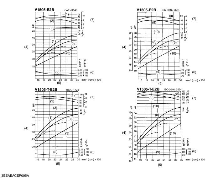
PERFORMANCE CURVES
(1) |
Gross Int. |
(4) |
Brake Horsepower |
(7) |
Torque |
(9) |
Overload |
(2) |
Net Int. |
(5) |
Engine Speed |
(8) |
Gross |
(10) |
Continuous |
(3) |
Net Cont. |
(6) |
Specified Fuel |
|
|
|
|
8 |
KiSC issued 06, 2011 A |
|
05-E2B, 05-E2BG, WSM |
PERFORMANCE CURVES |
|
|
|
|
(1) |
Gross Int. |
(4) |
Brake Horsepower |
(7) |
Torque |
(9) |
Overload |
(2) |
Net Int. |
(5) |
Engine Speed |
(8) |
Gross |
(10) |
Continuous |
(3) |
Net Cont. |
(6) |
Specified Fuel |
|
|
|
|
9 |
KiSC issued 06, 2011 A |
|
05-E2B, 05-E2BG, WSM |
PERFORMANCE CURVES |
|
|
|
|
|
|
|
(1) |
Gross Int. |
(4) |
Brake Horsepower |
(7) |
Torque |
(9) |
Overload |
(2) |
Net Int. |
(5) |
Engine Speed |
(8) |
Gross |
(10) |
Continuous |
(3) |
Net Cont. |
(6) |
Specified Fuel |
|
|
|
|
10 |
KiSC issued 06, 2011 A |
|
05-E2B, 05-E2BG, WSM |
DIMENSIONS |
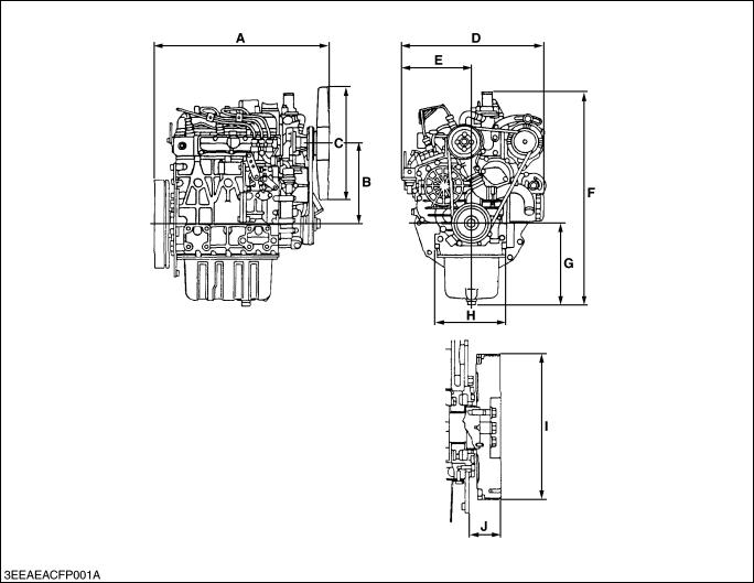
DIMENSIONS
|
|
|
|
|
Unit : mm (in.) |
|
|
D905-E2B |
D1005-E2B |
D1105-E2B |
D1105-T-E2B |
|
|
|
|
|
|
|
|
|
A |
497.8 (19.60) |
497.8 (19.60) |
497.8 (19.60) |
497.8 (19.60) |
|
|
|
|
|
|
|
|
|
B |
230 |
(9.06) |
230 (9.06) |
230 (9.06) |
230 (9.06) |
|
|
|
|
|
|
|
|
C |
320 dia. |
(12.6 dia.) |
330 dia. (12.99 dia.) |
330 dia. (12.99 dia.) |
330 dia. (12.99 dia.) |
|
|
|
|
|
|
|
|
D |
396 (15.59) |
396 (15.59) |
396 (15.59) |
396 (15.59) |
|
|
|
|
|
|
|
|
|
E |
194 |
(7.64) |
194 (7.64) |
194 (7.64) |
194 (7.64) |
|
|
|
|
|
|
|
|
F |
608.7 (23.96) |
608.7 (23.96) |
608.7 (23.96) |
608.7 (23.96) |
|
|
|
|
|
|
|
|
|
G |
233.5 (9.19) |
233.5 (9.19) |
233.5 (9.19) |
233.5 (9.19) |
|
|
|
|
|
|
|
|
|
H |
200 |
(7.87) |
200 (7.87) |
200 (7.87) |
200 (7.87) |
|
|
|
|
|
|
|
|
I |
250.81 to 251.12 dia. |
250.81 to 251.12 dia. |
250.81 to 251.12 dia. |
250.81 to 251.12 dia. |
|
|
(9.874 to 9.887 dia.) |
(9.874 to 9.887 dia.) |
(9.874 to 9.887 dia.) |
(9.874 to 9.887 dia.) |
|
||
|
|
|||||
|
|
|
|
|
|
|
J |
56 (2.20) |
56 (2.20) |
56 (2.20) |
56 (2.20) |
|
|
|
|
|
|
|
|
|
|
|
|
|
|
W1038971 |
|
11 |
KiSC issued 06, 2011 A |
|
05-E2B, 05-E2BG, WSM |
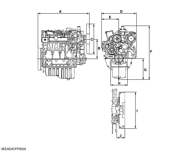
DIMENSIONS |
|
|
|
|
|
|
|
|
|
|
Unit : mm (in.) |
|
|
V1305-E2B |
V1505-E2B |
V1505-T-E2B |
|
|
|
|
|
|
A |
583.8 (22.98) |
591.3 (23.28) |
591.3 (23.28) |
|
|
|
|
|
|
B |
230 (9.06) |
230 (9.06) |
230 (9.06) |
|
|
|
|
|
|
C |
350 dia. (13.78 dia.) |
370 dia. (14.57 dia.) |
370 dia. (14.57 dia.) |
|
|
|
|
|
|
D |
396 (15.59) |
396 (15.59) |
396 (15.59) |
|
|
|
|
|
|
E |
194 (7.64) |
194 (7.64) |
194 (7.64) |
|
|
|
|
|
|
F |
613.7 (24.16) |
613.7 (24.16) |
629.3 (24.16) |
|
|
|
|
|
|
G |
238.5 (9.39) |
238.5 (9.39) |
238.5 (9.39) |
|
|
|
|
|
|
H |
200 (7.87) |
200 (7.87) |
200 (7.87) |
|
|
|
|
|
|
I |
250.81 to 251.12 dia. |
250.81 to 251.12 dia. |
250.81 to 251.12 dia. |
|
(9.874 to 9.887 dia.) |
(9.874 to 9.887 dia.) |
(9.874 to 9.887 dia.) |
|
|
|
|
|||
|
|
|
|
|
J |
56 (2.20) |
56 (2.20) |
56 (2.20) |
|
|
|
|
|
|
|
|
|
W1039589 |
|
12 |
KiSC issued 06, 2011 A |
|
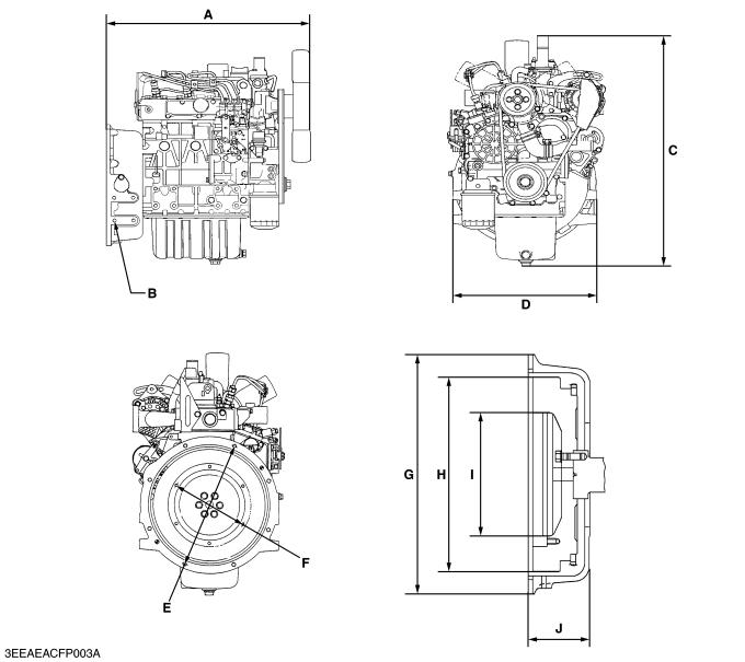
05-E2B, 05-E2BG, WSM |
DIMENSIONS |
|
|
|
|
|
|
|
|
|
Unit : mm (in.) |
|
|
D905-E2BG |
D1005-E2BG |
D1105-E2BG |
V1305-E2BG |
V1505-E2BG |
|
|
|
|
|
|
|
|
A |
546.6 (21.52) |
546.6 (21.52) |
546.6 (21.52) |
634.3 (24.97) |
634.3 (24.97) |
|
|
|
|
|
|
|
|
B |
4-3/8-16 UNC-2B |
4-3/8-16 UNC-2B |
4-3/8-16 UNC-2B |
4-3/8-16 UNC-2B |
4-3/8-16 UNC-2B |
|
Depth 16 (0.63) |
Depth 16 (0.63) |
Depth 16 (0.63) |
Depth 16 (0.63) |
Depth 16 (0.63) |
|
|
|
|
|||||
|
|
|
|
|
|
|
C |
608.7 (23.96) |
608.7 (23.96) |
608.7 (23.96) |
613.7 (24.16) |
613.7 (24.16) |
|
|
|
|
|
|
|
|
D |
360 (14.17) |
360 (14.17) |
360 (14.17) |
360 (14.17) |
360 (14.17) |
|
|
|
|
|
|
|
|
E |
333.38 dia. (13.13 dia.) |
333.38 dia. (13.13 dia.) |
333.38 dia. (13.13 dia.) |
333.38 dia. (13.13 dia.) |
333.38 dia. (13.13 dia.) |
|
|
|
|
|
|
|
|
F |
200.02 dia. (7.87 dia.) |
200.02 dia. (7.87 dia.) |
200.02 dia. (7.87 dia.) |
200.02 dia. (7.87 dia.) |
200.02 dia. (7.87 dia.) |
|
|
|
|
|
|
|
|
G |
356 dia. (14.02 dia.) |
356 dia. (14.02 dia.) |
356 dia. (14.02 dia.) |
356 dia. (14.02 dia.) |
356 dia. (14.02 dia.) |
|
|
|
|
|
|
|
|
H |
290 dia. (11.42 dia.) |
290 dia. (11.42 dia.) |
290 dia. (11.42 dia.) |
290 dia. (11.42 dia.) |
290 dia. (11.42 dia.) |
|
|
|
|
|
|
|
|
I |
184.2 dia. (7.25 dia.) |
184.2 dia. (7.25 dia.) |
184.2 dia. (7.25 dia.) |
184.2 dia. (7.25 dia.) |
184.2 dia. (7.25 dia.) |
|
|
|
|
|
|
|
|
J |
98 dia. (3.86 dia.) |
98 dia. (3.86 dia.) |
98 dia. (3.86 dia.) |
98 dia. (3.86 dia.) |
98 dia. (3.86 dia.) |
|
|
|
|
|
|
|
|
|
|
|
|
|
W1040012 |
|
13 |
KiSC issued 06, 2011 A |
|

GENERAL
CONTENTS
1. |
ENGINE IDENTIFICATION............................................................................. |
G-1 |
|
[1] MODEL NAME AND ENGINE SERIAL NUMBER ................................ |
G-1 |
|
[2] E2B ENGINE............................................................................................. |
G-2 |
|
[3] CYLINDER NUMBER ............................................................................... |
G-2 |
2. |
GENERAL PRECAUTIONS ............................................................................ |
G-3 |
3. |
MAINTENANCE CHECK LIST ....................................................................... |
G-4 |
4. |
CHECK AND MAINTENANCE....................................................................... |
G-6 |
|
[1] DAILY CHECK POINTS........................................................................... |
G-6 |
|
[2] CHECK POINTS OF INITIAL 50 HOURS ............................................. |
G-8 |
|
[3] CHECK POINTS OF EVERY 50 HOURS ........................................... |
G-10 |
|
[4] CHECK POINTS OF EVERY 100 HOURS ......................................... |
G-11 |
|
[5] CHECK POINTS OF EVERY 200 HOURS ......................................... |
G-13 |
|
[6] CHECK POINTS OF EVERY 400 HOURS ......................................... |
G-14 |
|
[7] CHECK POINTS OF EVERY 500 HOURS ......................................... |
G-15 |
|
[8] CHECK POINTS OF EVERY 1 OR 2 MONTHS ............................... |
G-17 |
|
[9] CHECK POINTS OF EVERY YEAR .................................................... |
G-18 |
|
[10]CHECK POINTS OF EVERY 800 HOURS ......................................... |
G-19 |
|
[11]CHECK POINTS OF EVERY 1500 HOURS ....................................... |
G-20 |
|
[12]CHECK POINTS OF EVERY 3000 HOURS ....................................... |
G-21 |
|
[13]CHECK POINTS OF EVERY 2 YEARS.............................................. |
G-24 |
5. |
SPECIAL TOOLS.......................................................................................... |
G-28 |
KiSC issued 06, 2011 A
05-E2B, 05-E2BG, WSM |
G GENERAL |
1. ENGINE IDENTIFICATION
[1] MODEL NAME AND ENGINE SERIAL NUMBER
|
When contacting the manufacture, always specify your engine |
|||||
model name and serial number. |
|
|
|
|
||
|
The engine model and its serial number need to be identified |
|||||
before the engine can be serviced or parts replaced. |
|
|||||
Q Engine Serial Number |
|
|
|
|
||
|
The engine serial number is an identified number for the engine. |
|||||
It is marked after the engine model number. |
|
|||||
|
It indicates month and year of manufacture as follows. |
|||||
• |
Year of manufacture |
|
|
|
|
|
|
|
|
|
|
|
|
|
Alphabet or |
Year |
|
Alphabet or |
|
Year |
|
Number |
|
Number |
|
||
|
|
|
|
|
||
|
|
|
|
|
|
|
|
1 |
2001 |
|
F |
|
2015 |
|
|
|
|
|
|
|
|
2 |
2002 |
|
G |
|
2016 |
|
|
|
|
|
|
|
|
3 |
2003 |
|
H |
|
2017 |
|
|
|
|
|
|
|
|
4 |
2004 |
|
J |
|
2018 |
|
|
|
|
|
|
|
|
5 |
2005 |
|
K |
|
2019 |
|
|
|
|
|
|
|
|
6 |
2006 |
|
L |
|
2020 |
|
|
|
|
|
|
|
|
7 |
2007 |
|
M |
|
2021 |
|
|
|
|
|
|
|
|
8 |
2008 |
|
N |
|
2022 |
|
|
|
|
|
|
|
|
9 |
2009 |
|
P |
|
2023 |
|
|
|
|
|
|
|
|
A |
2010 |
|
R |
|
2024 |
|
|
|
|
|
|
|
|
B |
2011 |
|
S |
|
2025 |
|
|
|
|
|
|
|
|
C |
2012 |
|
T |
|
2026 |
|
|
|
|
|
|
|
|
D |
2013 |
|
V |
|
2027 |
|
|
|
|
|
|
|
|
E |
2014 |
|
|
|
|
|
|
|
|
|
|
|
(1) |
Engine Label |
|
(3) |
Engine Model |
|
|
(2) |
Emission Label |
|
(4) |
Serial Number |
|
|
|
|
|
|
|
|
W1010477 |
G-1 |
KiSC issued 06, 2011 A |
|
05-E2B, 05-E2BG, WSM |
|
|
G GENERAL |
|
|
• Month of manufacture |
|
|
|
|
|
|
|
|
|
Month |
|
Engine Serial Number |
|
|
|
|
|
|
|
0001 |
~ 9999 |
10000 ~ |
|
|
|
|||
|
|
|
|
|
|
January |
A0001 |
~ A9999 |
B0001 ~ |
|
|
|
|
|
|
February |
C0001 |
~ C9999 |
D0001 ~ |
|
|
|
|
|
|
March |
E0001 |
~ E9999 |
F0001 ~ |
|
|
|
|
|
|
April |
G0001 |
~ G9999 |
H0001 ~ |
|
|
|
|
|
|
May |
J0001 |
~ J9999 |
K0001 ~ |
|
|
|
|
|
|
June |
L0001 |
~ L9999 |
M0001 ~ |
|
|
|
|
|
|
July |
N0001 |
~ N9999 |
P0001 ~ |
|
|
|
|
|
|
August |
Q0001 |
~ Q9999 |
R0001 ~ |
|
|
|
|
|
|
September |
S0001 |
~ S9999 |
T0001 ~ |
|
|
|
|
|
|
October |
U0001 |
~ U9999 |
V0001 ~ |
|
|
|
|
|
|
November |
W0001 |
~ W9999 |
X0001 ~ |
|
|
|
|
|
|
December |
Y0001 |
~ Y9999 |
Z0001 ~ |
|
|
|
|
|
e.g. D1105-4A0001
“4” indicates 2004 and “A” indicates January.
So, 4A indicates that the engine was manufactured in January, 2004.
W1011076
[2] E2B ENGINE
[ex. Model Name D1105-E2B]
The emission controls that have been put into effect in various countries to prevent air pollution will be stepped up. The time to enforce the regulations differs depending on the engine output classifications.
Kubota has been supplying the diesel engines conforming to the emission regulations in respective countries. Exhaust emissions regulations shift to the second stage. Kubota executed the improvement of the engine according to this regulation.
In order to discriminate the engines conforming to Tier 1 / Phase 1 requirements and those conforming to Tier 2 / Phase 2 requirements, we have adopted E2B as a new model name for the engines conforming Tier 2 / Phase 2 regulations.
In the after-sale services for 05-E2B and 05-E2BG series engines, only use the dedicated parts for E2B models and carry out the maintenance services accordingly.
[3] CYLINDER NUMBER
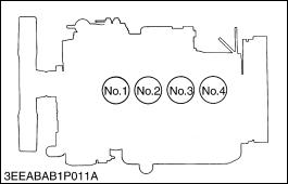
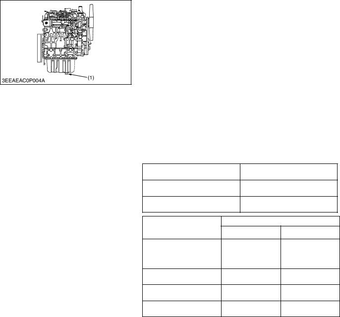
The cylinder numbers of kubota diesel engine are designated as shown in the figure.
The sequence of cylinder numbers is given as No.1, No.2, No.3 and No.4 starting from the gear case side.
W1011077
G-2 |
KiSC issued 06, 2011 A |
|
05-E2B, 05-E2BG, WSM |
G GENERAL |
2.GENERAL PRECAUTIONS
•During disassembly, carefully arrange removed parts in a clean area to prevent confusion later. Screws, bolts and nuts should be replaced in their original position to prevent reassembly errors.
•When special tools are required, use KUBOTA genuine special tools. Special tools which are not frequently used should be made according to the drawings provided.
•Before disassembling or servicing live wires, make sure to always disconnect the grounding cable from the battery first.
•Remove oil and dirt from parts before measuring.
•Use only KUBOTA genuine parts for parts replacement to maintain engine performance and to ensure safety.
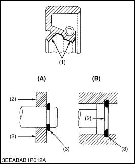
•Gaskets and O-rings must be replaced during reassembly. Apply grease to new O-rings or oil seals before assembling.
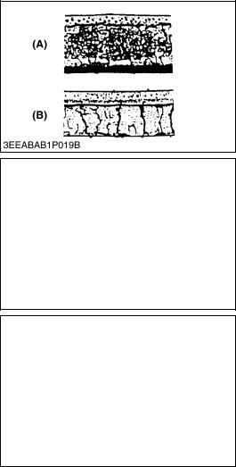
•When reassembling external or internal snap rings, position them so that the sharp edge faces against the direction from which force is applied.
•Be sure to perform run-in the serviced or reassembled engine. Do not attempt to give heavy load at once, or serious damage may result to the engine.
(1) |
Grease |
(A) External Snap Ring |
(2) |
Force |
(B) Internal Snap Ring |
(3)Place the Sharp Edge against the Direction of Force
W1011734
G-3 |
KiSC issued 06, 2011 A |
|
05-E2B, 05-E2BG, WSM |
G GENERAL |
3. MAINTENANCE CHECK LIST
To maintain long-lasting and safe engine performance, make it a rule to carry out regular inspections by following the table below.
|
|
|
|
|
Service Interval |
|
|
|
|
||
Item |
|
|
|
|
|
Every |
|
|
|
|
|
|
50 |
100 |
200 |
400 |
500 |
1 or 2 |
1 year |
800 |
1500 |
3000 |
2 years |
|
hrs |
hrs |
hrs |
hrs |
hrs |
months |
hrs |
hrs |
hrs |
||
* Checking fuel hoses and clamp bands |
, |
|
|
|
|
|
|
|
|
|
|
|
|
|
|
|
|
|
|
|
|
|
|
* Changing engine oil |
|
|
|
|
|
|
|
|
|
|
|
(Oil pan depth : 125 mm (4.92 in.), |
+ |
|
, |
|
|
|
|
|
|
|
|
130 mm (5.12 in.)) |
|
|
|
|
|
|
|
|
|
|
|
* Cleaning air cleaner element |
|
, |
|
|
|
|
|
|
|
|
|
(Replace the element after 6 times cleaning) |
|
|
|
|
|
|
|
|
|
|
|
|
|
|
|
|
|
|
|
|
|
|
|
Cleaning fuel filter element |
|
, |
|
|
|
|
|
|
|
|
|
|
|
|
|
|
|
|
|
|
|
|
|
Check fan belt tension and damage |
|
, |
|
|
|
|
|
|
|
|
|
|
|
|
|
|
|
|
|
|
|
|
|
Checking battery electrolyte level |
|
, |
|
|
|
|
|
|
|
|
|
|
|
|
|
|
|
|
|
|
|
|
|
* Replacing oil filter cartridge |
|
|
|
|
|
|
|
|
|
|
|
(Oil pan depth : 125 mm (4.92 in.), |
+ |
|
, |
|
|
|
|
|
|
|
|
130 mm (5.12 in.)) |
|
|
|
|
|
|
|
|
|
|
|
Checking radiator hoses and clamp bands |
|
|
, |
|
|
|
|
|
|
|
|
|
|
|
|
|
|
|
|
|
|
|
|
* Checking intake air line |
|
|
, |
|
|
|
|
|
|
|
|
|
|
|
|
|
|
|
|
|
|
|
|
Replacing fuel filter cartridge |
|
|
|
, |
|
|
|
|
|
|
|
|
|
|
|
|
|
|
|
|
|
|
|
Cleaning water jacket and radiator interior |
|
|
|
|
, |
|
|
|
|
|
|
|
|
|
|
|
|
|
|
|
|
|
|
Replacing fan belt |
|
|
|
|
, |
|
|
|
|
|
|
|
|
|
|
|
|
|
|
|
|
|
|
Recharging battery |
|
|
|
|
|
, |
|
|
|
|
|
|
|
|
|
|
|
|
|
|
|
|
|
* Replacing air cleaner element |
|
|
|
|
|
|
, |
|
|
|
|
|
|
|
|
|
|
|
|
|
|
|
|
Checking valve clearance |
|
|
|
|
|
|
|
, |
|
|
|
|
|
|
|
|
|
|
|
|
|
|
|
* Checking injection nozzle pressure |
|
|
|
|
|
|
|
|
, |
|
|
|
|
|
|
|
|
|
|
|
|
|
|
* Checking turbocharger |
|
|
|
|
|
|
|
|
|
, |
|
|
|
|
|
|
|
|
|
|
|
|
|
Checking injection pump |
|
|
|
|
|
|
|
|
|
, |
|
|
|
|
|
|
|
|
|
|
|
|
|
Checking injection timing |
|
|
|
|
|
|
|
|
|
, |
|
|
|
|
|
|
|
|
|
|
|
|
|
Changing radiator coolant (L.L.C.) |
|
|
|
|
|
|
|
|
|
|
, |
|
|
|
|
|
|
|
|
|
|
|
|
Replacing radiator hoses and clamp bands |
|
|
|
|
|
|
|
|
|
|
, |
|
|
|
|
|
|
|
|
|
|
|
|
* Replacing fuel hoses and clamps |
|
|
|
|
|
|
|
|
|
|
, |
|
|
|
|
|
|
|
|
|
|
|
|
* Replacing intake air line |
|
|
|
|
|
|
|
|
|
|
, |
|
|
|
|
|
|
|
|
|
|
|
|
Replacing battery |
|
|
|
|
|
|
|
|
|
|
, |
|
|
|
|
|
|
|
|
|
|
|
|
+ Change engine oil and replace oil filter cartridge after the first 50 hours of operation.
* The items listed above (* marked) are registered as emission related critical parts by KUBOTA in the U.S. EPA nonroad emission regulation. As the engine owner, you are responsible for the performance of the required maintenance on the engine according to the above instruction.
W1029462
G-4 |
KiSC issued 06, 2011 A |
|
05-E2B, 05-E2BG, WSM |
G GENERAL |
 CAUTION
•When changing or inspecting, be sure to level and stop the engine. Q NOTE
Lubricating Oil
With the emission control now in effect, the CF-4 and CG-4 lubricating oils have been developed for use of a lowsulfur fuel on-road vehicle engines. When an off-road vehicle engine runs on a high-sulfur fuel, it is advisable to employ the CF, CD or CE lubricating oil with a high total base number. If the CF-4 or CG-4 lubricating oil is used with a high-sulfur fuel, change the lubricating oil at shorter intervals.
•Lubricating oil recommended when a low-sulfur or high-sulfur fuel is employed.
|
Fuel |
Low sulfur |
|
|
|
|
High sulfur |
Remarks |
|
Lubricating |
|
(0.5 % ≥) |
||
|
|
|
||
oil class |
|
|
|
|
|
|
|
|
|
CF |
|
P |
P |
TBN ≥ 10 |
|
|
|
|
|
CF-4 |
|
P |
X |
|
|
|
|
|
|
CG-4 |
|
P |
X |
|
|
|
|
|
|
P : Recommendable X : Not recommendable
W1035555
G-5 |
KiSC issued 06, 2011 A |
|
05-E2B, 05-E2BG, WSM |
G GENERAL |
4. CHECK AND MAINTENANCE
[1] DAILY CHECK POINTS
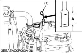
Checking Engine Oil Level
1.Level the engine.
2.To check the oil level, draw out the dipstick (1), wipe it clean, reinsert it, and draw it out again.
Check to see that the oil level lies (A) between the two notches.
3.If the level is too low, add new oil to the specified level.
Q IMPORTANT
•When using an oil of different maker or viscosity from the previous, drain old oil. Never mix two different types of oil.
Q NOTE
•Be sure to inspect the engine, locating it on a horizontal place. If placed on gradients, accurately, oil quantity may not be measured.
•Be sure to keep the oil level between upper and lower limits of the dipstick. Too much oil may cause a drop in output or excessive blow-by gas. On the closed breather type engine in which mist is sucked through port, too much oil may caused oil hammer. While too little oil, may seize the engine’s rotating and sliding parts.
(1) Dipstick |
A : Oil Level |
W1016222
G-6 |
KiSC issued 06, 2011 A |
|
05-E2B, 05-E2BG, WSM |
G GENERAL |
Checking and Replenish Coolant
1.Without recovery tank :
Remove the radiator cap (1) and check to see that the coolant level is just below the port.
With recovery tank (2) :
Check to see that the coolant level lies between FULL (A) and
LOW (B).
2.If coolant level is too low, check the reason for decreasing coolant.
(Case 1)
If coolant is decreasing by evaporation, replenish only fresh, soft water.
(Case 2)
If coolant is decreasing by leak, replenish coolant of the same manufacture and type in the specified mixture ratio (fresh, soft water and L.L.C.). If the coolant brand cannot be identified, drain out all of the remaining coolant and refill with a totally new brand of coolant mix.
 CAUTION
•Do not remove the radiator cap until coolant temperature is below its boiling point. Then loosen the cap slightly to relieve any excess pressure before removing the cap completely.
Q IMPORTANT
•During filling the coolant, air must be vented from the engine coolant passages. The air vents by jiggling the radiator upper and lower hoses.
•Be sure to close the radiator cap securely. If the cap is loose or improperly closed, coolant may leak out and the engine could overheat.
•Do not use an antifreeze and scale inhibitor at the same time.
•Never mix the different type or brand of L.L.C..
(1) |
Radiator Cap |
A: |
FULL |
(2) |
Recovery Tank |
B: |
LOW |
W1035779
G-7 |
KiSC issued 06, 2011 A |
|
05-E2B, 05-E2BG, WSM |
G GENERAL |
[2] CHECK POINTS OF INITIAL 50 HOURS
Changing Engine Oil
 CAUTION
• Be sure to stop engine before changing engine oil.
1.Start and warm up the engine for approx. 5 minutes.
2.Place an oil pan underneath the engine.
3.To drain the used oil, remove the drain plug (1) at the bottom of the engine and drain the oil completely.
4.Screw the drain plug (1).
5.Fill new oil up to upper line on the dipstick.
Q IMPORTANT
•When using an oil of different maker or viscosity from the previous one, remove all of the old oil.
•Never mix two different types of oil.
•Engine oil should have properties of API classification CD/ CE/CF/CF-4/CG-4.
•Use the proper SAE Engine Oil according to ambient temperature.
•Upon an oil change, be sure to replace the gasket with new one.
Above 25 °C (77 °F) |
SAE 30 or SAE 10W-30 |
||
SAE 10W-40 |
|||
|
|||
0 °C to 25 °C (32 °F to 77 °F) |
SAE 20 or SAE 10W-30 |
||
SAE 10W-40 |
|||
|
|||
Below 0 °C (32 °F) |
SAE 10W or SAE 10W-30 |
||
|
SAE 10W-40 |
||
|
|
||
Oil pan depth |
Capacity |
||
Models |
125 mm (4.92 in.) |
130 mm (5.12 in.) |
|
|
|
||
D905-E2B / E2BG |
|
|
|
D1005-E2B /E2BG |
5.1 L |
– |
|
D1105-E2B /E2BG |
1.35 U.S.gals |
||
|
|||
D1105-T-E2B |
|
|
|
V1305-E2B |
6.0 L |
– |
|
V1505-E2B |
1.59 U.S.gals |
||
|
|||
V1305-E2BG |
– |
6.7 L |
|
V1505-E2BG |
1.77 U.S.gals |
||
|
|||
V1505-T-E2B |
– |
6.7 L |
|
1.77 U.S.gals |
|||
|
|
||
|
|
|
|
32.4 to 37.3 N·m |
|
|
M12 |
× 1.25 |
3.3 to 3.8 kgf·m |
|
Drain plug with |
|
|
23.9 to 27.5 ft-lbs |
Tightening |
copper gasket |
|
|
63.7 to 73.5 N·m |
|
M22 |
× 1.5 |
6.5 to 7.5 kgf·m |
|
torque |
|
|||
|
|
|
47.0 to 54.2 ft-lbs |
|
|
|
|
|
|
|
|
|
|
|
|
Drain plug with |
|
|
44.1 to 53.9 N·m |
|
rubber coated |
M22 |
× 1.5 |
4.5 to 5.5 kgf·m |
|
gasket |
|
|
32.5 to 39.8 ft-lbs |
|
|
|
|
|
(1) Drain Plug
W1016604
G-8 |
KiSC issued 06, 2011 A |
|
05-E2B, 05-E2BG, WSM |
G GENERAL |
Replacing Oil Filter Cartridge
 CAUTION
• Be sure to stop the engine before changing filter cartridge.
1.Remove the oil filter cartridge with the filter wrench.
2.Apply a slight coat of oil onto the new cartridge gasket.
3.To install the new cartridge, screw it in by hand. Over tightening may cause deformation of rubber gasket.
4.After the new cartridge has been replaced, the engine oil normally decrease a little. Thus see that the engine oil does not leak through the seal and be sure to read the oil level on the dipstick. Then, replenish the engine oil up to the specified level.
Q IMPORTANT
•To prevent serious damage to the engine, replacement element must be highly efficient. Use only a KUBOTA genuine filter or its equivalent.
W1017137
G-9 |
KiSC issued 06, 2011 A |
|
05-E2B, 05-E2BG, WSM |
G GENERAL |
[3] CHECK POINTS OF EVERY 50 HOURS
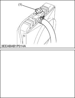
Checking Fuel Hose
1.If the clamp (2) is loose, apply oil to the threads and securely retighten it.
2.The fuel hose (1) is made of rubber and ages regardless of the period service.
Change the fuel hose together with the clamp every two years.
3.However, if the fuel hose and clamp are found to be damaged or deteriorate earlier than two years, then change or remedy.
4.After the fuel hose and the clamp have been changed, bleed the fuel system.
 CAUTION
•Stop the engine when attempting the check and change prescribed above.
(When bleeding fuel system)
1.Fill the tank with fuel and open the cock (4).
2.Loosen the air vent plug (3) of the fuel filter a few turns.
3.Screw back the plug when bubbles do not come up any more.
4.Open the air vent cock on top of the fuel injection pump.
5.If equipped electrical fuel feed pump, turn the key to AC position and pump the fuel up for 10 to 15 seconds.
If equipped mechanical fuel feed pump, set the stop lever on stop position and crank the engine for 10 to 15 seconds.
6.Close securely the air vent cock after air bleeding.
Q NOTE
•Always keep the air vent cock on the fuel injection pump closed except when air is vented, or it may cause the engine to stop.
(1) |
Fuel Hose |
[A] Cartridge Type |
(2) |
Clamp |
[B] Element Type |
(3)Air Vent Plug
(4)Fuel Cock
W1035921
G-10 |
KiSC issued 06, 2011 A |
|
05-E2B, 05-E2BG, WSM |
G GENERAL |
[4] CHECK POINTS OF EVERY 100 HOURS
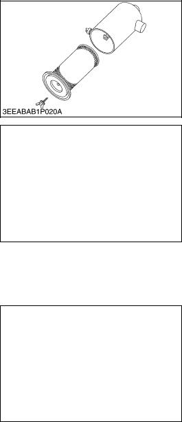
Cleaning Air Cleaner Element
1.Remove the air cleaner element.
2.Use clean dry compressed air on the inside of the element. Pressure of compressed air must be under 205 kPa (2.1 kgf/cm2, 30 psi).
Maintain reasonable distance between the nozzle and the filter.
Q NOTE
•The air cleaner uses a dry element. Never apply oil to it.
•Do not run the engine with filter element removed.
•Change the element once a year or every 6th cleaning.
W1045746
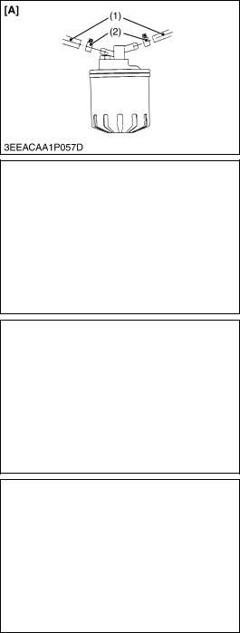
Cleaning Fuel Filter (Element Type only)
1.Close the fuel cock (3).
2.Unscrew the retaining ring (6) and remove the filter cup (5), and rinse the inside with kerosene.
3.Take out the element (4) and dip it in the kerosene to rinse.
4.After cleaning, reassemble the fuel filter, keeping out dust and dirt.
5.Bleed the fuel system.
Q IMPORTANT
•If dust and dirt enter the fuel, the fuel injection pump and injection nozzle will wear quickly. To prevent this, be sure to clean the fuel filter cup (5) periodically.
(1) |
Cock Body |
(4) |
Filter Element |
(2) |
Air Vent Plug |
(5) |
Filter Cup |
(3) |
Fuel Cock |
(6) |
Retaining Ring |
W1046058
Fan Belt Tension
1.Measure the deflection (A), depressing the belt halfway between the fan drive pulley and alternator pulley at specified force 98 N (10 kgf, 22 lbs).
2.If the measurement is not within the factory specifications, loosen the alternator mounting screws and relocate the alternator to adjust.
Deflection (A) |
Factory spec. |
7.0 to 9.0 mm |
|
0.28 to 0.35 in. |
|||
|
|
||
|
|
|
|
(A) Deflection |
|
|
W1208957
G-11 |
KiSC issued 06, 2011 A |
|
05-E2B, 05-E2BG, WSM |
G GENERAL |
Fan Belt Damage and Wear
1.Check the fan belt for damage.
2.If the fan belt is damaged, replace it.
3.Check if the fan belt is worn and sunk in the pulley groove.
4.If the fan belt is nearly worn out and deeply sunk in the pulley groove, replace it.
(A) Good |
(B) Bad |
W1209480
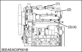
Checking Battery Electrolyte Level
1.Check the battery electrolyte level.
2.If the level is below than lower level line (2), and the distilled water to pour level of each cell.
(1) Upper Level Line |
(2) Lower Level Line |
W1047154
G-12 |
KiSC issued 06, 2011 A |
|
05-E2B, 05-E2BG, WSM |
G GENERAL |
[5] CHECK POINTS OF EVERY 200 HOURS
Changing Engine Oil
 CAUTION
• Be sure to stop engine before changing engine oil.
1.Start and warm up the engine for approx. 5 minutes.
2.Place an oil pan underneath the engine.
3.To drain the used oil, remove the drain plug (1) at the bottom of the engine and drain the oil completely.
4.Screw the drain plug (1).
5.Fill new oil up to upper line on the dipstick.
Q IMPORTANT
•When using an oil of different maker or viscosity from the previous one, remove all of the old oil.
•Never mix two different types of oil.
•Engine oil should have properties of API classification CD/ CE/CF/CF-4/CG-4.
•Use the proper SAE Engine Oil according to ambient temperature.
•Upon an oil change, be sure to replace the gasket with new one.
Above 25 °C (77 °F) |
SAE 30 or SAE 10W-30 |
||
SAE 10W-40 |
|||
|
|||
0 °C to 25 °C (32 °F to 77 °F) |
SAE 20 or SAE 10W-30 |
||
SAE 10W-40 |
|||
|
|||
Below 0 °C (32 °F) |
SAE 10W or SAE 10W-30 |
||
|
SAE 10W-40 |
||
|
|
||
Oil pan depth |
Capacity |
||
Models |
125 mm (4.92 in.) |
130 mm (5.12 in.) |
|
|
|
||
D905-E2B / E2BG |
|
|
|
D1005-E2B /E2BG |
5.1 L |
– |
|
D1105-E2B /E2BG |
1.35 U.S.gals |
||
|
|||
D1105-T-E2B |
|
|
|
V1305-E2B |
6.0 L |
– |
|
V1505-E2B |
1.59 U.S.gals |
||
|
|||
V1305-E2BG |
– |
6.7 L |
|
V1505-E2BG |
1.77 U.S.gals |
||
|
|||
V1505-T-E2B |
– |
6.7 L |
|
1.77 U.S.gals |
|||
|
|
||
|
|
|
|
32.4 to 37.3 N·m |
|
|
M12 |
× 1.25 |
3.3 to 3.8 kgf·m |
|
Drain plug with |
|
|
23.9 to 27.5 ft-lbs |
Tightening |
copper gasket |
|
|
63.7 to 73.5 N·m |
|
M22 |
× 1.5 |
6.5 to 7.5 kgf·m |
|
torque |
|
|||
|
|
|
47.0 to 54.2 ft-lbs |
|
|
|
|
|
|
|
|
|
|
|
|
Drain plug with |
|
|
44.1 to 53.9 N·m |
|
rubber coated |
M22 |
× 1.5 |
4.5 to 5.5 kgf·m |
|
gasket |
|
|
32.5 to 39.8 ft-lbs |
|
|
|
|
|
(1) Drain Plug
W1018298
G-13 |
KiSC issued 06, 2011 A |
|
05-E2B, 05-E2BG, WSM |
G GENERAL |
Replacing Oil Filter Cartridge
 CAUTION
• Be sure to stop the engine before changing filter cartridge.
1.Remove the oil filter cartridge with the filter wrench.
2.Apply a slight coat of oil onto the new cartridge gasket.
3.To install the new cartridge, screw it in by hand. Over tightening may cause deformation of rubber gasket.
4.After the new cartridge has been replaced, the engine oil normally decrease a little. Thus see that the engine oil does not leak through the seal and be sure to read the oil level on the dipstick. Then, replenish the engine oil up to the specified level.
Q IMPORTANT
•To prevent serious damage to the engine, replacement element must be highly efficient. Use only a KUBOTA genuine filter or its equivalent.
W1018617
Checking Radiator Hoses and Clamp Bands
1.Check to see if the radiator hoses are properly fixed every 200 hours of operation or every six months, whichever comes first.
2.If the clamp is loose, apply oil to the threads and retighten it securely.
3.The water hose is made of rubber and tens to age. It must be replaced every two years. Also replace the clamp and tighten it securely.
(1) Upper Hose |
(2) Lower Hose |
W1029518
Checking Intake Air Line
1.Check to see if the intake air hose(s) are properly fixed every 200 hours of operation.
2.If the clamp is loose, apply oil to the threads and retighten it securely.
3.The intake air hose(s) is made of rubber and tends to age. It must be changed every two years. Also change the clamp and tighten it securely.
Q IMPORTANT
•To prevent serious damage to the engine, keep out any dust inside the intake air line.
(1) Intake Air Hose |
(2) Clamp |
W1029631
[6] CHECK POINTS OF EVERY 400 HOURS
Replacing Fuel Filter Cartridge (Cartridge Type)
Water and dust in fuel are collected in the filter cartridge. So, change the filter cartridge every 400 hours service.
1.Remove the used filter cartridge with filter wrench.
2.Apply a thin film of fuel to the surface of new filter cartridge gasket before screwing on.
3.Then tighten enough by hand.
4.Loosen the air vent plug to let the air out.
5.Start engine and check for fuel leakage.
(1)Fuel Filter Cartridge
W1050548
G-14 |
KiSC issued 06, 2011 A |
|
 Loading...