

Page 1

Quick Start
Quick Start
TIDALFLUX 2300 F
TIDALFLUX 2300 F
TIDALFLUX 2300 FTIDALFLUX 2300 F
Quick StartQuick Start
Electromagnetic flow sensor for partially filled pipes
The documentation is only complete when used in combination with the relevant
documentation for the signal converter.
© KROHNE 11/2018 - 4002489404 - QS TIDALFLUX 2300 R04 en
Page 2

CONTENTS
TIDALFLUX 2300 F
1 Safety instructions 3
2 Installation 4
2.1 Scope of delivery............................................................................................................... 4
2.2 Device description ............................................................................................................ 4
2.3 Nameplates ...................................................................................................................... 5
2.4 Storage ............................................................................................................................. 6
2.5 Transport .......................................................................................................................... 6
2.6 Pre-installation requirements ......................................................................................... 7
2.7 General requirements...................................................................................................... 7
2.7.1 Vibration .................................................................................................................................. 7
2.7.2 Magnetic field.......................................................................................................................... 7
2.8 Installation conditions ...................................................................................................... 8
2.8.1 Inlet and outlet........................................................................................................................ 8
2.8.2 Control valve ........................................................................................................................... 8
2.8.3 Slope........................................................................................................................................ 8
2.8.4 Mounting advice for difficult situations ..................................................................................9
2.8.5 Open discharge .......................................................................................................................9
2.8.6 Cleaning of flow sensor ........................................................................................................ 10
2.8.7 Flange deviation.................................................................................................................... 10
2.8.8 Mounting position.................................................................................................................. 11
2.8.9 Torques and pressures......................................................................................................... 11
2.8.10 Temperatures ..................................................................................................................... 12
3 Electrical connections 13
3.1 Safety instructions.......................................................................................................... 13
3.2 Important notes on electrical connection...................................................................... 13
3.3 Connection of cables ...................................................................................................... 14
3.4 Connection of TIDALFLUX 2000 F .................................................................................. 16
3.5 Cable lengths.................................................................................................................. 18
3.6 Signal cable B (type BTS 300), construction .................................................................. 19
3.7 Signal cable A (type DS 300), construction .................................................................... 19
3.8 Preparing signal cable A, connection to flow sensor .................................................... 20
3.9 Preparing signal cable B, connection to flow sensor .................................................... 21
3.10 Preparing field current cable C, connection to flow sensor........................................ 22
3.11 Interface cable.............................................................................................................. 23
3.12 Grounding ..................................................................................................................... 25
3.12.1 Mounting grounding rings .................................................................................................. 25
3.13 Before switching on the power.................................................................................... 25
4 Technical data 26
4.1 Dimensions and weights ................................................................................................ 26
2
www.krohne.com 11/2018 - 4002489404 - QS TIDALFLUX 2300 R04 en
Page 3
TIDALFLUX 2300 F
Warnings and symbols used
DANGER!
This information refers to the immediate danger when working with electricity.
DANGER!
These warnings must be observed without fail. Even partial disregard of this warning can lead to
serious health problems and even death. There is also the risk of seriously damaging the device
or parts of the operator's plant.
WARNING!
Disregarding this safety warning, even if only in part, poses the risk of serious health problems.
There is also the risk of damaging the device or parts of the operator's plant.
CAUTION!
Disregarding these instructions can result in damage to the device or to parts of the operator's
plant.
INFORMATION!
These instructions contain important information for the handling of the device.
SAFETY INSTRUCTIONS
1
HANDLING
• This symbol designates all instructions for actions to be carried out by the operator in the
specified sequence.
i
RESULT
RESULT
RESULTRESULT
This symbol refers to all important consequences of the previous actions.
Safety instructions for the operator
CAUTION!
Installation, assembly, start-up and maintenance may only be performed by appropriately
trained personnel. The regional occupational health and safety directives must always be
observed.
LEGAL NOTICE!
The responsibility as to the suitability and intended use of this device rests solely with the user.
The supplier assumes no responsibility in the event of improper use by the customer. Improper
installation and operation may lead to loss of warranty. In addition, the "Terms and Conditions of
Sale" apply which form the basis of the purchase contract.
INFORMATION!
•
Further information can be found on the supplied CD-ROM in the manual, on the data sheet,
in special manuals, certificates and on the manufacturer's website.
•
If you need to return the device to the manufacturer or supplier, please fill out the form
contained on the CD-ROM and send it with the device. Unfortunately, the manufacturer
cannot repair or inspect the device without the completed form.
www.krohne.com11/2018 - 4002489404 - QS TIDALFLUX 2300 R04 en
3
Page 4
2
INSTALLATION
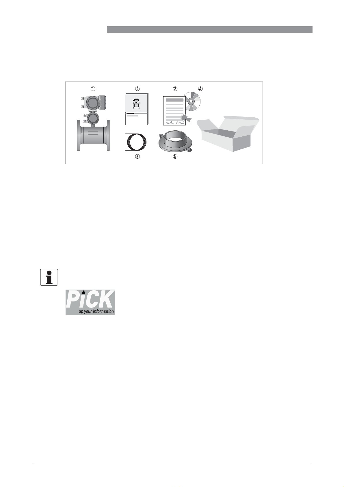
2.1 Scope of delivery
Figure 2-1: Scope of delivery
1 Ordered flowmeter
2 Product documentation
3 Factory calibration report
4 CD-ROM with product documentation
5 Grounding rings (optionally)
6 Cable
TIDALFLUX 2300 F
2.2 Device description
This flowmeter can measure the flow of conductive liquids, even in partially filled pipes. To be
able to do this, a capacitive height measurement has been integrated into a regular
electromagnetic flowmeter. If both the filled fraction and the velocity of the fluid are known, it is
easy to calculate the amount of fluid running through the pipe.
INFORMATION!
Product specific information and extensive product specification is available using PICK, the
Product Information Center KROHNE web-tool.
PICK can be found via the service menu button on the KROHNE.com website.
4
www.krohne.com 11/2018 - 4002489404 - QS TIDALFLUX 2300 R04 en
Page 5
TIDALFLUX 2300 F
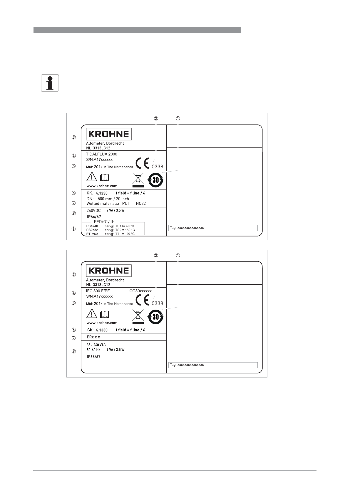
2.3 Nameplates
INFORMATION!
Look at the device nameplate to ensure that the device is delivered according to your order.
Check for the correct supply voltage printed on the nameplate.
INSTALLATION
2
Figure 2-2: Example of nameplate sensor and converter
1 Additional info, website and recycling logo
2 CE marking with number(s) of notified body (bodies)
3 Name and address of manufacturer
4 Type designation with serial / CG number
5 Manufacturing date and country of origin
6 GK/GKL values (measuring sensor constants), size (mm/inches), field frequency
7 Materials of wetted parts or the Electronic Revision number
8 Electric values and protection category
9 PED data type I/II/III or SEP
www.krohne.com11/2018 - 4002489404 - QS TIDALFLUX 2300 R04 en
5
Page 6
2
INSTALLATION
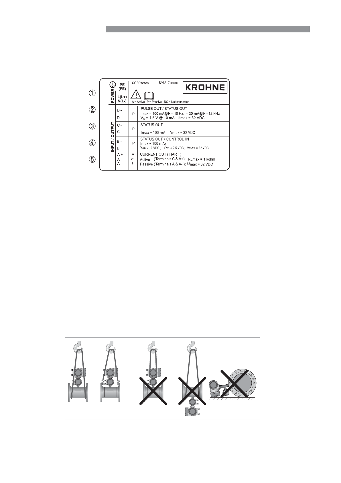
Electrical connection data of inputs/outputs (example of basic version)
Electrical connection data of inputs/outputs (example of basic version)
Electrical connection data of inputs/outputs (example of basic version)Electrical connection data of inputs/outputs (example of basic version)
Figure 2-3: Example of IO sticker
1 Power supply (AC: L and N, DC: L+ and L-, PE for ≥ 24V AC, FE for ≤ 24 VAC and DC)
2 Connection data of connection terminal D/D-
3 Connection data of connection terminal C/C-
4 Connection data of connection terminal B/B-
5 Connection data of connection terminal A/A-, A+ only operable in basic version
TIDALFLUX 2300 F
á A = active mode; the signal converter supplies the power for connection of the subsequent devices
á P = passive mode; external power supply required for operation of the subsequent devices
á N/C = connection terminals not connected
2.4 Storage
á Store the device in a dry and dust-free location.
á Avoid lasting direct exposure to the sun.
á Store the device in its original packaging.
á Storage temperature: -50...+70° C / -58...+158° F
2.5 Transport
Figure 2-4: Transport
6
www.krohne.com 11/2018 - 4002489404 - QS TIDALFLUX 2300 R04 en
Page 7
TIDALFLUX 2300 F
2.6 Pre-installation requirements
Make sure that you have all necessary tools available:
• Allen key (4 mm)
• Small screwdriver
• Wrench for cable glands
• Wrench for wall mounting bracket (remote version only)
• Torque wrench for installing flowmeter in pipeline
2.7 General requirements
INFORMATION!
The following precautions must be taken to ensure reliable installation.
•
Make sure that there is adequate space to the sides.
•
Protect the signal converter from direct sunlight and install a sun shade if necessary.
•
Signal converters installed in control cabinets require adequate cooling, e.g. by fan or heat
exchanger.
•
Do not expose the signal converter to intense vibration. The flowmeters are tested for a
vibration level in accordance with IEC 68-2-64.
INSTALLATION
2
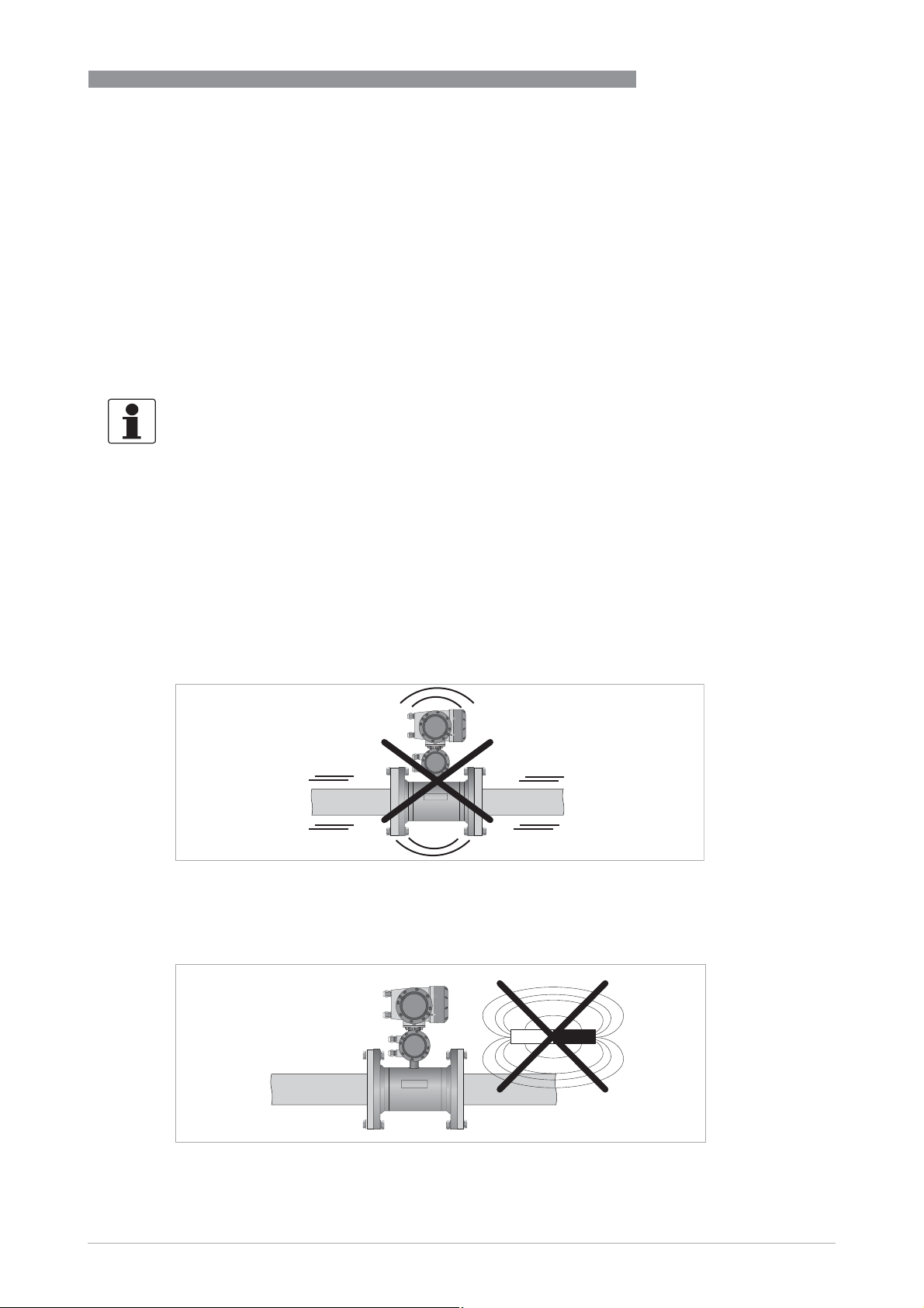
2.7.1 Vibration
Figure 2-5: Avoid vibrations
2.7.2 Magnetic field
Figure 2-6: Avoid magnetic fields
www.krohne.com11/2018 - 4002489404 - QS TIDALFLUX 2300 R04 en
7
Page 8
2
INSTALLATION
2.8 Installation conditions
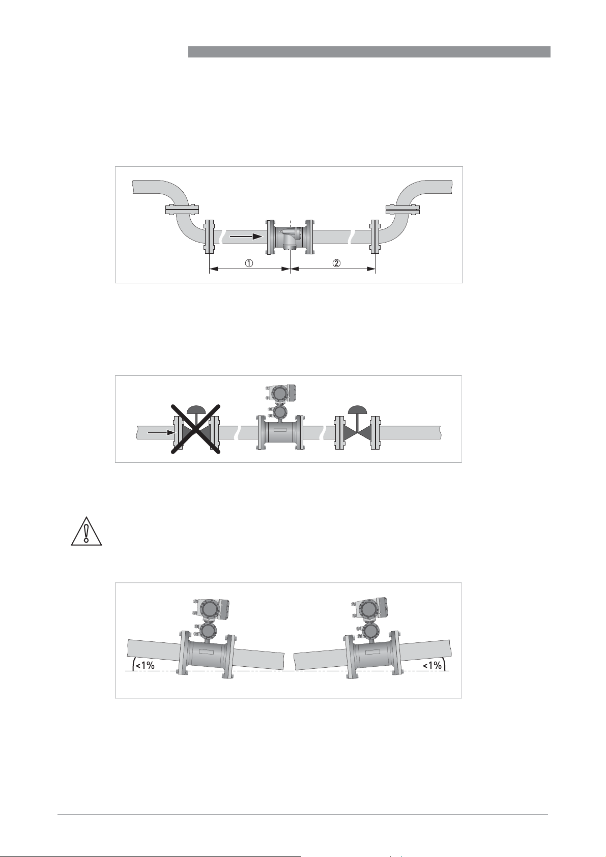
2.8.1 Inlet and outlet
Figure 2-7: Recommended inlet and outlet sections, top view
1 t 5 DN
2 t 3 DN
2.8.2 Control valve
TIDALFLUX 2300 F
2.8.3 Slope
Figure 2-8: Installation before control valve
CAUTION!
The accuracy is influenced by the slope. Stay within
measurements!
Figure 2-9: Recommended slope
±
1% to get the most accurate
8
www.krohne.com 11/2018 - 4002489404 - QS TIDALFLUX 2300 R04 en
Page 9
TIDALFLUX 2300 F
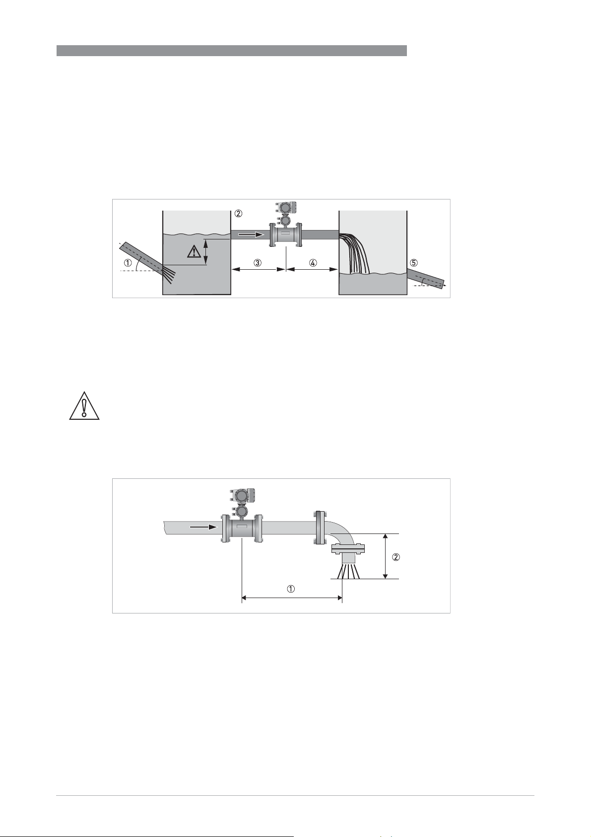
2.8.4 Mounting advice for difficult situations
If you can not meet the installation conditions install the flowmeter between two containers. The
inlet to the flowmeter must be higher than the outlet of the fluid. In this way you will have a calm
flow into the flowmeter, resulting in a highly accurate measurement. The sizes of the containers
must be proportional to the size of the flowmeter.
Figure 2-10: Installing in difficult situations
1 Use a container 2 if the Inlet pipe has a slope > 1%. Make sure that the outlet level of this pipe is below the inlet to the
flowmeter.
2 Inlet container
3 Inlet section of 10 DN
4 Outlet section of 5 DN
5 Outlet container advisable if outlet pipe has a slope > 1%.
INSTALLATION
2
CAUTION!
Always use a free exit pipe to prevent backflow in the flow sensor and to keep the velocity at the
maximum flow at least at 1 m/s.
2.8.5 Open discharge
Figure 2-11: Open discharge
1 t 5 DN
2 Make sure that the water level stays below the pipe outlet.
www.krohne.com11/2018 - 4002489404 - QS TIDALFLUX 2300 R04 en
9
Page 10
2
INSTALLATION
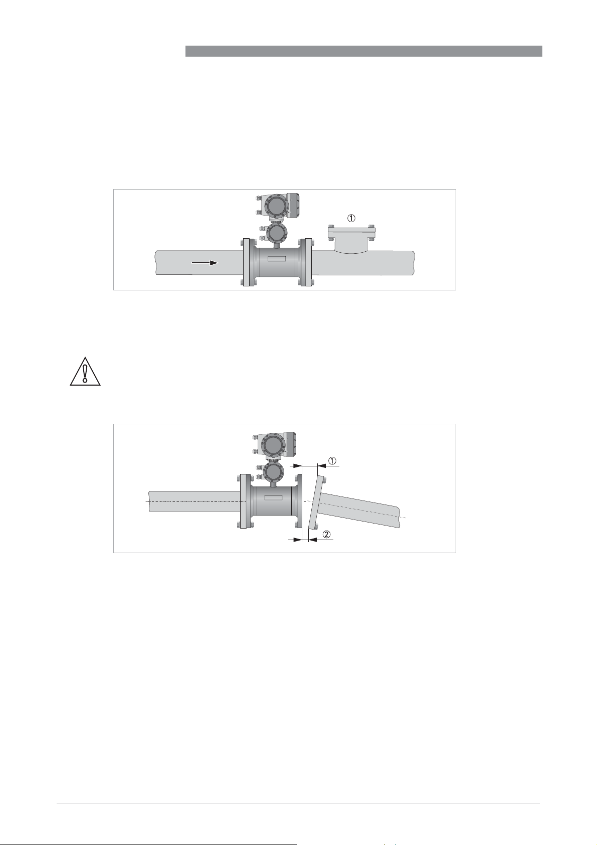
2.8.6 Cleaning of flow sensor
The flow sensor is highly resistant against dirt and the measurement will rarely be influenced by
anything. However, it is advisable to create a possiblity for cleaning just in front or behind the
sensor.
Figure 2-12: Option for cleaning of flow sensor
1 Opening for cleaning
2.8.7 Flange deviation
TIDALFLUX 2300 F
CAUTION!
Max. permissible deviation of pipe flange faces:
- L
L
max
Figure 2-13: Flange deviation
1 L
max
2 L
min
d 0.5 mm / 0.02"
min
10
www.krohne.com 11/2018 - 4002489404 - QS TIDALFLUX 2300 R04 en
Page 11

TIDALFLUX 2300 F
2.8.8 Mounting position
CAUTION!
Only install the flow sensor in the shown position to keep the electrodes under water. Limit the
rotation to
Figure 2-14: Mounting position
±2°
to maintain the accuracy.
INSTALLATION
2
2.8.9 Torques and pressures
Figure 2-15: Tightening of bolts
Tightening of bolts
• Always tighten the bolts uniformly and in diagonally opposite sequence.
• Do not exceed the maximum torque value.
• Step 1: Apply approx. 50% of max. torque given in table.
• Step 2: Apply approx. 80% of max. torque given in table.
• Step 3: Apply 100% of max. torque given in table.
www.krohne.com11/2018 - 4002489404 - QS TIDALFLUX 2300 R04 en
11
Page 12

2
INSTALLATION
INFORMATION!
Tighten the bolts uniformely in diagonally opposite sequence.
TIDALFLUX 2300 F
Nominal size
DN [mm]
Nominal size
[inch]
Pressure
Bolts Max. torque [Nm]
r a t i n g
200 PN 10 8 x M 20 68
250 PN 10 12 x M 20 65
300 PN 10 12 x M 20 76
350 PN 10 16 x M 20 75
400 PN 10 16 x M 24 104
500 PN 10 20 x M 24 107
600 PN 10 20 x M 27 138
700 PN 10 24 x M 27 163
800 PN 10 24 x M 30 219
900 PN 10 28 x M 30 205
1000 PN 10 28 x M 33 261
1200 PN 6 32 x M30 252
Flange class
Bolts Max. torque [Nm]
[lb]
8 150 8 x 3/4" 69
10 150 12 x 7/8" 79
12 150 12 x 7/8" 104
14 150 12 x 1" 93
16 150 16 x 1" 91
18 150 16 x 1 1/8" 143
20 150 20 x 1 1/8" 127
24 150 20 x 1 1/4" 180
28 150 28 x 1 1/4" 161
32 150 28 x 1 1/2" 259
36 150 32 x 1 1/2" 269
40 150 36 x 1 1/2" 269
INFORMATION!
Information for bigger sizes is available on request.
2.8.10 Temperatures
Temperature range Process [°C] Ambient [°C] Process [°F] Ambient [°F]
All versions 0 60 -40 65 32 140 -40 149
12
min. max. min. max. min. max. min. max.
www.krohne.com 11/2018 - 4002489404 - QS TIDALFLUX 2300 R04 en
Page 13

TIDALFLUX 2300 F
3.1 Safety instructions
DANGER!
All work on the electrical connections may only be carried out with the power disconnected. Take
note of the voltage data on the nameplate!
DANGER!
Observe the national regulations for electrical installations!
WARNING!
Observe without fail the local occupational health and safety regulations. Any work done on the
electrical components of the measuring device may only be carried out by properly trained
specialists.
INFORMATION!
Look at the device nameplate to ensure that the device is delivered according to your order.
Check for the correct supply voltage printed on the nameplate.
ELECTRICAL CONNECTIONS
3
3.2 Important notes on electrical connection
DANGER!
Electrical connection is carried out in conformity with the VDE 0100 directive "Regulations for
electrical power installations with line voltages up to 1000 V" or equivalent national regulations.
CAUTION!
•
Use suitable cable entries for the various electrical cables.
•
The sensor and converter are configured together in the factory. For this reason, please
connect the devices in pairs. Ensure that the sensor constant GK (see nameplates) are
identically set.
•
The TIDALFLUX 2300 sensor and converter need both a separate power supply.
INFORMATION!
For more information about the grounding of the flowmeter, refer to Grounding on page 25
.
www.krohne.com11/2018 - 4002489404 - QS TIDALFLUX 2300 R04 en
13
Page 14

3
ELECTRICAL CONNECTIONS
3.3 Connection of cables
The illustration shows the different connections and cable entries. View "p" shows (explicit) the
bottom entries for signal and field current cables into the connection box on the signal
converter.
INFORMATION!
For more detailed information refer to the following electrical diagrams and illustrations in the
TIDALFLUX 2300 manual.
TIDALFLUX 2300 F
Figure 3-1: Cable entries for electrical connection
1 View "p" of the connection box of the signal converter
2 Field current cable
3 Signal cable (DS or BTS)
4 Interface cable
5 Flow sensor
14
www.krohne.com 11/2018 - 4002489404 - QS TIDALFLUX 2300 R04 en
Page 15

TIDALFLUX 2300 F
INFORMATION!
The next drawing shows the situation for a signal cable type BTS. In case of a signal cable type
DS, terminals 20 and 30 are not used.
ELECTRICAL CONNECTIONS
3
Figure 3-2: Connection diagram
1 Connection box of signal converter
2 I/O connection box of flow sensor
3 Connection box of flow sensor
4 Connect the outer screens via strain reliefs
5 Labelled wires for connection on terminals E-C-D in connection box
www.krohne.com11/2018 - 4002489404 - QS TIDALFLUX 2300 R04 en
15
Page 16

3
ELECTRICAL CONNECTIONS
3.4 Connection of TIDALFLUX 2000 F
The flow sensor and the signal converter must be incorporated in the equipotential bonding
system of the installation. This can be established internally by connection of the protective
earth (PE) conductor of the mains supply system to the internal PE clamp, or externally, by
connecting a separate equipotential bonding conductor between the two external PE-clamps
(size M5). A separate bonding conductor must have a cross-sectional area of at least 4 mm
Keep the screw-threads free of dirt and well-greased (e.g. with PTFE grease). The grease will
help to prevent the threads from locking due to corrosion.
To unscrew the covers, first release the interlocking devices (one at each cover). Therefore
unscrew the M4 head screw with an internal hexagon socket set using a HEX or Allen key no. 2.5
until the interlocking device can be turned. After the covers are screwed back onto the housing,
make sure that the interlocking devices are properly refitted.
CAUTION!
The TIDALFLUX 2300 sensor and converter need both a separate power supply.
TIDALFLUX 2300 F
2
.
16
Figure 3-3: Electrical connections
1 Unscrew interlocking head screw
2 Turn cover counter-clockwise and remove
3 Open / close safety lid of mains supply section
4 Mains supply & signal / data terminals
www.krohne.com 11/2018 - 4002489404 - QS TIDALFLUX 2300 R04 en
Page 17

TIDALFLUX 2300 F
Figure 3-4: Electrical connections
1 Unscrew interlocking head screw
2 Turn cover counter-clockwise and remove
3 Open / close safety lid of mains supply section
4 Mains supply & signal / data terminals
ELECTRICAL CONNECTIONS
3
Description of connections
Terminals
Terminals Cable wire colour
TerminalsTerminals
L, N
L+, L-
CD
D-
Cable wire colour Function, electrical data
Cable wire colourCable wire colour
black 3
black 1
black 2
Function, electrical data
Function, electrical dataFunction, electrical data
Connections for mains supply,
Type of protection Ex e,
100...230 VAC, +10%/-15%, VA
12...24 VDC, +30%/-10% (short-time: -25%), W
U
= 253 V
m
Connections for RS 485 circuit,
Type of protection Ex ia.
www.krohne.com11/2018 - 4002489404 - QS TIDALFLUX 2300 R04 en
17
Page 18

3
ELECTRICAL CONNECTIONS
3.5 Cable lengths
CAUTION!
The maximum allowed distance between the flow sensor and the converter is determined by the
shortest cable length.
Interface cable
Interface cable: maximum length is 600 m / 1968 ft.
Interface cableInterface cable
Type B (BTS) signal cable
Type B (BTS) signal cable: maximum length is 600 m / 1968 ft.
Type B (BTS) signal cableType B (BTS) signal cable
Type A (DS) signal cable
Type A (DS) signal cable: maximum length depends on the conductivity of the fluid:
Type A (DS) signal cableType A (DS) signal cable
Electrical conductivity Maximum length
[μS/cm] [m] [ft]
50 120 394
100 200 656
200 400 1312
t400 600 1968
TIDALFLUX 2300 F
Field current cable
Field current cable: The cross section of the cable determines the maximum length:
Field current cableField current cable
Cross section Maximum length
[mm2]
2 x 0.75 2 x 18 150 492
2 x 1.5 2 x 16 300 984
2 x 2.5 2 x 14 600 1968
[AWG] [m] [ft]
18
www.krohne.com 11/2018 - 4002489404 - QS TIDALFLUX 2300 R04 en
Page 19

TIDALFLUX 2300 F
ELECTRICAL CONNECTIONS
3.6 Signal cable B (type BTS 300), construction
• Signal cable B is a triple-shielded cable for signal transmission between the flow sensor and
signal converter.
• Bending radius: t 50 mm / 2"
Figure 3-5: Construction of signal cable B
1 Stranded drain wire for the inner shield (10), 1.0 mm
2 Insulated wire (2), 0.5 mm
3 Insulated wire (3), 0.5 mm
4 Outer sheath
5 Insulation layers
6 Stranded drain wire (6) for the outer shield (60), 0.5 mm
2
Cu / AWG 20 with stranded drain wire (20) of shield
2
Cu / AWG 20 with stranded drain wire (30) of shield
2
Cu / AWG 17 (not insulated, bare)
2
Cu / AWG 20 (not insulated, bare)
3
3.7 Signal cable A (type DS 300), construction
• Signal cable A is a double-shielded cable for signal transmission between the flow sensor
and signal converter.
• Bending radius: t 50 mm / 2"
Figure 3-6: Construction of signal cable A
1 Stranded drain wire (1) for the inner shield (10), 1.0 mm
2 Insulated wire (2), 0.5 mm
3 Insulated wire (3), 0.5 mm
4 Outer sheath
5 Insulation layers
6 Stranded drain wire (6) for the outer shield (60)
2
Cu / AWG 20
2
Cu / AWG 20
2
Cu / AWG 17 (not insulated, bare)
www.krohne.com11/2018 - 4002489404 - QS TIDALFLUX 2300 R04 en
19
Page 20
3
ELECTRICAL CONNECTIONS
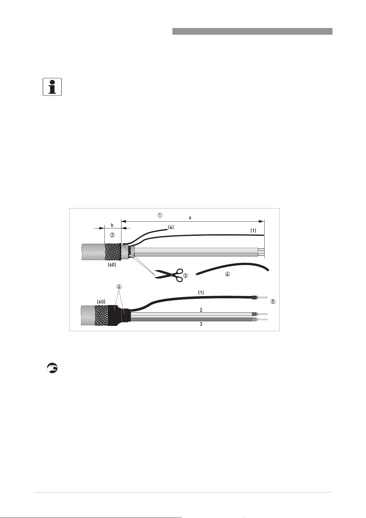
3.8 Preparing signal cable A, connection to flow sensor
INFORMATION!
Assembly materials and tools are not part of the delivery. Use the assembly materials and tools
in compliance with the applicable occupational health and safety directives.
• The outer shield (60) is connected in the terminal compartment of the flow sensor directly via
the shield and a clip.
• Bending radius: t 50 mm / 2"
Required materials
• PVC insulating tube, Ø2.0...2.5 mm / 0.08...0.1"
• Heat-shrinkable tubing
• Wire end ferrule to DIN 46228: E 1.5-8 for the stranded drain wire (1)
• 2 wire end ferrules to DIN 46228: E 0.5-8 for the insulated conductors (2, 3)
TIDALFLUX 2300 F
20
Figure 3-7: Preparing signal cable A, connection to flow sensor
a = 50 mm / 2"
b = 10 mm / 0.4"
1 Strip the conductor to dimension a.
2 Trim the outer shield (60) to dimension b and pull it over the outer sheath.
3 Remove the stranded drain wire (6) of the outer shield and the inner shield. Make sure not to
damage the stranded drain wire (1) of the inner shield.
4 Slide an insulating tube over the stranded drain wire (1).
5 Crimp the wire end ferrules onto conductors 2 and 3 and the stranded drain wire (1).
6 Pull the heat-shrinkable tubing over the prepared signal cable.
www.krohne.com 11/2018 - 4002489404 - QS TIDALFLUX 2300 R04 en
Page 21

TIDALFLUX 2300 F
ELECTRICAL CONNECTIONS
3.9 Preparing signal cable B, connection to flow sensor
INFORMATION!
Assembly materials and tools are not part of the delivery. Use the assembly materials and tools
in compliance with the applicable occupational health and safety directives.
• The outer shield (60) is connected in the terminal compartment of the flow sensor directly via
the shield and a clip.
• Bending radius: t 50 mm / 2"
Required materials
• PVC insulating tube, Ø2.0...2.5 mm / 0.08...0.1"
• Heat-shrinkable tubing
• Wire end ferrule to DIN 46228: E 1.5-8 for the stranded drain wire (1)
• 2 wire end ferrules to DIN 46228: E 0.5-8 for the insulated conductors (2, 3)
3
Figure 3-8: Preparing signal cable B, connection to flow sensor
a = 50 mm / 2"
b = 10 mm / 0.4"
1 Strip the conductor to dimension a.
2 Trim the outer shield (60) to dimension b and pull it over the outer sheath.
3 Remove the stranded drain wire (6) of the outer shield and the shields and stranded drain
wires of the insulated conductors (2, 3). Remove the inner shield. Be sure not to damage the
stranded drain wire (1).
4 Slide an insulating tube over the stranded drain wire (1).
5 Crimp the wire end ferrules onto conductors 2 and 3 and the stranded drain wire (1).
6 Pull the heat-shrinkable tubing over the prepared signal cable.
www.krohne.com11/2018 - 4002489404 - QS TIDALFLUX 2300 R04 en
21
Page 22

3
ELECTRICAL CONNECTIONS
3.10 Preparing field current cable C, connection to flow sensor
INFORMATION!
Assembly materials and tools are not part of the delivery. Use the assembly materials and tools
in compliance with the applicable occupational health and safety directives.
• The field current cable is not part of the scope of delivery.
• The shield is connected in the terminal compartment of the signal converter directly via the
shield and a clip.
• The shield is connected in the flow sensor via the special cable gland.
• Bending radius: t 50 mm / 2"
Required materials
• Shielded 2-wire insulated copper cable
• Insulating tube, size according to the cable being used
• Heat-shrinkable tubing
• DIN 46 228 wire end ferrules: size according to the cable being used
TIDALFLUX 2300 F
Figure 3-9: Preparation of field current cable C
a = 125 mm / 5"
b = 10 mm / 0.4"
1 Strip the conductor to dimension a.
2 Trim the outer shield to dimension b and pull it over the outer sheath.
3 Crimp wire end ferrules onto both conductors.
22
www.krohne.com 11/2018 - 4002489404 - QS TIDALFLUX 2300 R04 en
Page 23

TIDALFLUX 2300 F
3.11 Interface cable
The data interface cable is a shielded, 3 x 1.5 mm2 LIYCY cable.
Preparing the interface cable
Figure 3-10: Preparing the interface cable
a = 100 mm / 4"
b = 10 mm / 0.4"
ELECTRICAL CONNECTIONS
3
1 Strip the conductor to dimension a.
2 Trim the outer shield to dimension b and pull it over the outer sheath.
3 Crimp the wire end ferrules onto the conductors 1, 2 and 3.
Connect the shielding at both sides of the cable via the special cable gland.
www.krohne.com11/2018 - 4002489404 - QS TIDALFLUX 2300 R04 en
23
Page 24

3
ELECTRICAL CONNECTIONS
At signal converter side:
Connecting shielding under clamp in connection box of converter
Figure 3-11: Clamping of shields
1 Field current cable
2 Signal cable
At flow sensor side:
Connecting shielding via special cable gland
TIDALFLUX 2300 F
24
Figure 3-12: Connecting the shield within the cable gland
1 Wires
2 Isolation
3 Shielding
4 Isolation
5 Feed cable through dome nut and clamping insert and fold shielding over clamping insert. Make sure that the braided
shield overlaps the O-ring by 2 mm / 3/32".
6 Push clamping insert into body.
7 Tighten the dome nut.
www.krohne.com 11/2018 - 4002489404 - QS TIDALFLUX 2300 R04 en
Page 25

TIDALFLUX 2300 F
3.12 Grounding
DANGER!
The device must be grounded in accordance with regulations in order to protect personnel
against electric shocks.
3.12.1 Mounting grounding rings
CAUTION!
In order to get a reliable height measurement it is absolutely necessary
connecting pipeline is electrically conductive and connected to ground. If not, tailor-made
grounding rings with a cylindrical part can be delivered. Please contact your local agency in case
of doubt.
ELECTRICAL CONNECTIONS
absolutely necessary that the inner side of the
absolutely necessaryabsolutely necessary
3
Figure 3-13: Grounding with grounding rings
1 Existing pipeline
2 Grounding rings, custom made to inner diameter of pipeline
3 TIDALFLUX
4 Insert the cylindrical part of the grounding ring into the pipeline. Use an appropiate gasket between the grounding ring
and the flange.
INFORMATION!
Sizes of the grounding rings are diameter dependent and available on request.
3.13 Before switching on the power
Before switching on the power, please check that the system has been correctly
installed. This includes:
• The device must be mechanically mounted safely in compliance with the regulations.
• The power connections must be in compliance with the regulations.
• Make sure that all electrical connections are made and that the covers of the terminal
compartments are closed.
• Check that the electrical operating data of the power supply are correct.
• Switch on the power.
INFORMATION!
The sensor can not be programmed or changed in any way. All settable functions are included in
the converter. Please see the relevant documentation of the converter for more information.
www.krohne.com11/2018 - 4002489404 - QS TIDALFLUX 2300 R04 en
25
Page 26

4
TECHNICAL DATA
4.1 Dimensions and weights
The inner pipe diameter should match the inner diameter of the flowmeter. Since the inner
diameter is not a standard DN size, choose the inner pipe diameter to be just a little bit bigger
than the flowmeter diameter. If a lot of sediment or fat is expected the optimal solution is to use
a customized diameter compensation ring on both sides to have smooth transits.
TIDALFLUX 2300 F
k = 230 mm / 89.1"
m = 265 mm / 10.4"
n = 251 mm / 9.9"
INFORMATION!
Detailed 2D and 3D drawings are available on the website of the manufacturer.
EN 1092-1
Nominal size Dimensions [mm] Approx.
DN PN a b Øc d ØD ØD
200 10 350 582 291 146 340 189 40
250 10 400 630 331 166 395 231 54
300 10 500 680 381 191 445 281 66
350 10 500 733 428 214 505 316 95
400 10 600 791 483 242 565 365 115
500 10 600 894 585 293 670 467 145
600 10 600 1003 694 347 780 567 180
700 10 700 1120 812 406 895 666 265
800 10 800 1235 922 461 1015 768 350
900 10 900 1356 1064 532 1115 863 425
1000 10 1000 1447 1132 566 1230 965 520
1200 6 1200 1639 1340 670 1405 1169 659
1400 6 1400 1842 1521 761 1630 1367 835
1600 6 1600 2042 1721 861 1830 1549 1659
i
weight
[kg]
26
www.krohne.com 11/2018 - 4002489404 - QS TIDALFLUX 2300 R04 en
Page 27

TIDALFLUX 2300 F
150 lb flanges
Nominal size Dimensions [inches] Approx.
ASME 1PN
1 Nominal size d 24": ASME; > 24": AWWA
TECHNICAL DATA
a b Øc d ØD ØD
[psi]
8 284 13.78 22.93 11.46 5.75 13.5 7.44 90
10 284 15.75 24.80 13.03 6.54 16.0 9.09 120
12 284 19.69 26.76 15 7.52 19.0 11.06 145
14 284 27.56 30.22 16.85 9.8 21.0 12.44 210
16 284 31.5 31.13 19.02 9.53 23.5 14.37 255
20 284 31.5 35.21 23.03 11.54 27.5 18.39 320
24 284 31.5 39.50 27.32 13.66 32.0 22.32 400
28 Class D 35.43 44.71 31.97 15.98 36.5 26.22 692
32 Class D 39.37 49.51 36.3 18.15 41.8 30.24 1031
36 Class D 43.31 54.42 41.89 20.94 46.0 33.98 1267
40 Class D 47.24 58.14 44.57 22.28 50.8 37.99 1554
48 Class D 55.12 66.61 52.76 26.38 59.5 46.02 2242
weight
i
[lb]
4
www.krohne.com11/2018 - 4002489404 - QS TIDALFLUX 2300 R04 en
27
Page 28

KROHNE – Process instrumentation and measurement solutions
•
Flow
•
Level
•
Temperature
•
Pressure
•
Process Analysis
•
Services
Head Office KROHNE Messtechnik GmbH
Ludwig-Krohne-Str. 5
47058 Duisburg (Germany)
Tel.: +49 203 301 0
Fax: +49 203 301 10389
info@krohne.com
© KROHNE 11/2018 - 4002489404 - QS TIDALFLUX 2300 R04 en - Subject to change without notice.
The current list of all KROHNE contacts and addresses can be found at:
www.krohne.com
 Loading...