

Page 1

Supplementary instructions
Supplementary instructions
OPTITEMP TRA/TCA
OPTITEMP TRA/TCA
OPTITEMP TRA/TCAOPTITEMP TRA/TCA
Supplementary instructions Supplementary instructions
Industrial thermometers with replaceable measuring
inserts.
Category
II 1/2 G
II 1 G
II 1 D
© KROHNE 10/2010 - 4001087001 - Ex AD OPTITEMP TRA/TCA R02 en
Page 2

CONTENTS
OPTITEMP TRA/TCA
1 Safety instructions 3
1.1 General notes ................................................................................................................... 3
1.2 EC conformity ................................................................................................................... 3
1.3 Safety instructions............................................................................................................ 3
2 Device description 4
2.1 Device description ............................................................................................................ 4
2.2 Description code............................................................................................................... 5
2.3 Marking............................................................................................................................. 7
2.4 Flammable products ........................................................................................................ 7
2.5 Equipment category .........................................................................................................8
2.6 Protection types................................................................................................................ 9
2.6.1 Protection type with zone separator for gas hazard areas.................................................... 9
2.6.2 Type of protection for gas hazard areas................................................................................. 9
2.6.3 Type of protection for dust hazard areas ............................................................................. 10
2.7 Temperature classes..................................................................................................... 11
2.7.1 Maximum permitted product temperature .......................................................................... 12
2.7.2 Temperature at process connection (without temperature transmitter)............................ 13
2.7.3 Temperature at process connection (with temperature transmitter) ................................15
2.7.4 Temperature at process connection (with temperature transmitter, classes T5 and T6).. 17
2.7.5 Temperature at process connection for thermometers with connecting cable................. 18
2.8 Electrical data................................................................................................................. 20
3 Installation 21
3.1 Selecting the right thermometer and calculating limit values ..................................... 21
3.2 Assembly ........................................................................................................................ 25
4 Electrical connections 26
4.1 General notes ................................................................................................................. 26
4.2 Power supply .................................................................................................................. 26
4.3 Inputs / Outputs.............................................................................................................. 27
4.3.1 Pt100 measuring inserts....................................................................................................... 27
4.3.2 Thermocouple measuring inserts ........................................................................................ 27
4.4 Grounding and equipotential bonding............................................................................ 28
5 Operation 29
5.1 Starting up for the first time .......................................................................................... 29
5.2 Operation ........................................................................................................................ 29
6 Service 30
6.1 Maintenance ................................................................................................................... 30
6.2 Dismantling .................................................................................................................... 30
2
www.krohne.com 10/2010 - 4001087001 - Ex AD OPTITEMP TRA/TCA R02 en
Page 3

OPTITEMP TRA/TCA
1.1 General notes
These additional "Ex" instructions apply to explosion-protected models of industrial
thermometers with the marking II 1/2 G, II 1 G and II 1 D. They complement the standard
documentation for non-explosion-protected models.
The information given in these Instructions contains only the data relevant to Category 1
explosion protection. The technical details given in the standard documentation for the nonexplosion protected versions apply unchanged unless excluded or superseded by these
Instructions.
1.2 EC conformity
The manufacturer declares with the EC Declaration of Conformity on his own responsibility
conformity with the protection goals of Directive 94/9/EC for use in hazardous areas with gas.
The EC Type Test Certificate of the Physikalisch Technische Bundesanstalt (PTB) forms the basis
of the EC Declaration of Conformity:
SAFETY INSTRUCTIONS 1
The "X" after the certificate number refers to special conditions for safe use of the device as
described in these Instructions.
You can download the EC Type Test Certificate from the manufacturer's website as needed.
1.3 Safety instructions
Assembly, installation, start-up and maintenance may only be performed by personnel trained in
explosion protection!
CAUTION!
Should operating conditions and locations require the observance of further standards,
guidelines and laws, this is the responsibility of the operator and/or those commissioned by him.
PTB 10 ATEX 2017 X
PTB 10 ATEX 2017 X
PTB 10 ATEX 2017 XPTB 10 ATEX 2017 X
www.krohne.com10/2010 - 4001087001 - Ex AD OPTITEMP TRA/TCA R02 en
3
Page 4
2 DEVICE DESCRIPTION
2.1 Device description
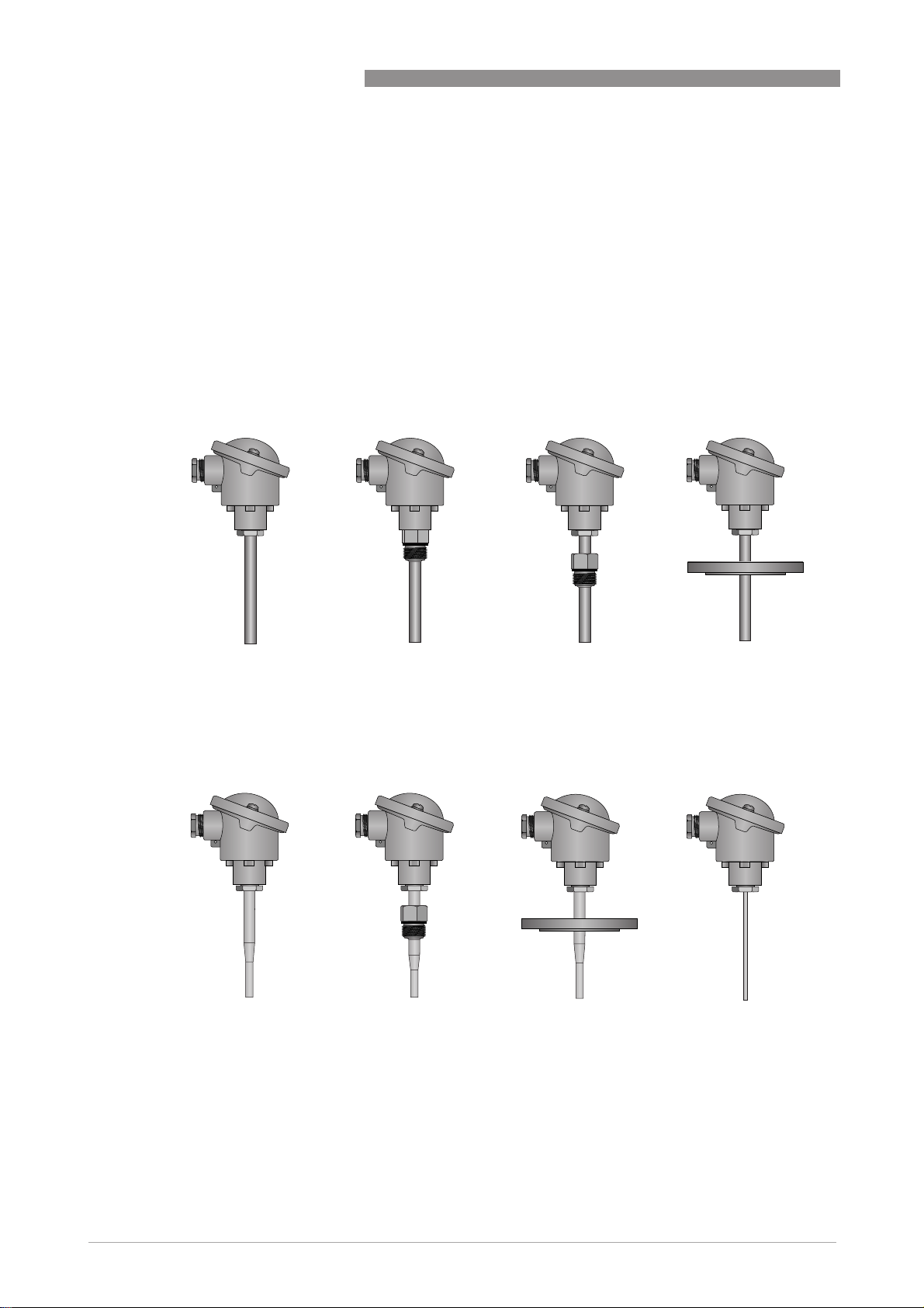
Industrial thermometers measure the temperature of flammable and non-flammable gases and
liquids. They consist of a thermometer assembly comprising a connection head and usually a
thermowell (only version TRA/TCA-P14 does not have a thermowell).
The thermometer assembly contains a measuring insert, which can have either a thermocouple
or a Pt100 measuring resistor as sensor. The manufacturer offers measuring inserts with a
terminal block, free connection wires or a directly fitted head-mounted transmitter.
Standard version (straight thermowells)
Standard version (straight thermowells)
Standard version (straight thermowells)Standard version (straight thermowells)
TRA-P10 / TCA-P10
TRA-P10 / TCA-P10 TRA-S11 / TCA-S11
TRA-P10 / TCA-P10TRA-P10 / TCA-P10
TRA-S11 / TCA-S11 TRA-S12 / TCA-S12
TRA-S11 / TCA-S11TRA-S11 / TCA-S11
OPTITEMP TRA/TCA
TRA-S12 / TCA-S12 TRA-F13 / TCA-F13
TRA-S12 / TCA-S12TRA-S12 / TCA-S12
TRA-F13 / TCA-F13
TRA-F13 / TCA-F13TRA-F13 / TCA-F13
With tapered tip
With tapered tip Without thermowell
With tapered tipWith tapered tip
TRA-P40 / TCA-P40
TRA-P40 / TCA-P40 TRA-S41 / TCA-S41
TRA-P40 / TCA-P40TRA-P40 / TCA-P40
TRA-S41 / TCA-S41 TRA-F42 / TCA-F42
TRA-S41 / TCA-S41TRA-S41 / TCA-S41
TRA-F42 / TCA-F42 TRA-P14 / TCA-P14
TRA-F42 / TCA-F42TRA-F42 / TCA-F42
Without thermowell
Without thermowellWithout thermowell
TRA-P14 / TCA-P14
TRA-P14 / TCA-P14TRA-P14 / TCA-P14
4
www.krohne.com 10/2010 - 4001087001 - Ex AD OPTITEMP TRA/TCA R02 en
Page 5
OPTITEMP TRA/TCA
2.2 Description code
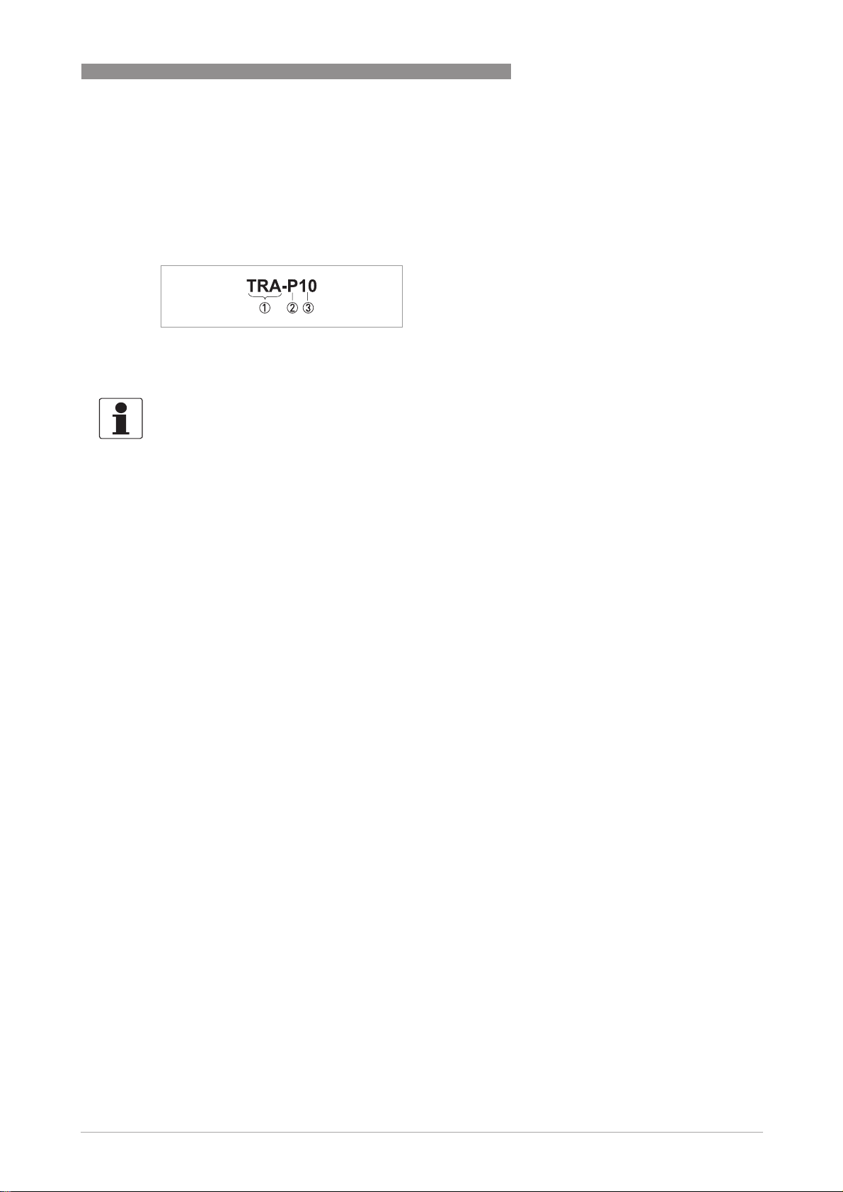
The safety description code of the measuring inserts is made up of the model name and the VGC
key. The following are examples to help explain the composition of the model name and the VGC
key:
Model name
1 Sensor type: TCA = thermocouple, TRA = resistance thermometer
2 Type of process connection: P = insert version, S = threaded version, F = flange version
3 Internal manufacturer's designation of thermowell version
INFORMATION!
In the following chapters of this manual the model names of the thermometers start with "TxA"
to avoid using the full title "TRA/TCA". Blanks in the VGC key can be omitted.
DEVICE DESCRIPTION 2
www.krohne.com10/2010 - 4001087001 - Ex AD OPTITEMP TRA/TCA R02 en
5
Page 6
2 DEVICE DESCRIPTION
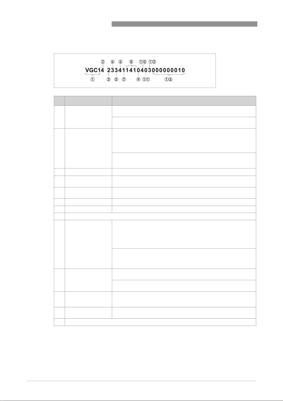
VGC key
Designation Variants
OPTITEMP TRA/TCA
1 Type of thermowell tip
2 Abbreviation for full
description of
thermometer
3 Ex-Approval 0 = without; 2 = ATEX- Ex-i
4 Type of connection
head
5 Sensor circuit type 0 = without; 1 = 1xPt100 2-wire; 2 = 1xPt100 3-wire; 3 = 1xPt100 4-wire;
6 Sensor class 4 = class A, Mi, WW;, A = Class 1, thermocouple
7 Thermowell material 0 = without; 1 = 1,4571, 316Ti; 2 = 1,4841, 314
8 Not Ex-relevant
9 Insertion length For VGC1: 0 = without; 1 = 75 mm / 2.95"; 2 = 100 mm / 3.94"; 3 = 115 mm /
10 Length of neck pipe For VGC1: 0 = without; 1 = 80 mm / 3.15"; 3 = 145 mm / 5.71; Z = special
11 Connection type
(head-mounted
transmitter)
12 Connection type (rail-
mount transmitter)
13 Not Ex-relevant (14th to 20th position), not used (21st to 25th position)
VGC 1 = straight tip
VGC 4 = tapered tip
For VGC1: 1 = TRA-P10 (insert version); 2 = TRA-S11 (threaded version);
3 = TRA-S12 (threaded version); 4 = TRA-F13 (flange version); A = TCA-P10
(insert version); B = TCA-S11 (threaded version);
C = TCA-S12 (threaded version); D = TCA-F13 (flange version); L = TRAP14 (without thermowell); T = TCA-P14 (without thermowell)
For VGC4: 1 = TRA-P40 (insert version); 2 = TRA-S41 (threaded version);
3 = TRA-F42 (flange version); A = TCA-P40 (insert version); B = TCA-S41
(threaded version);C = TCA-F42 (flange version)
3=BUZ-T; 5=BUZ-H
A = 1xthermocouple type J; B = 1xthermocouple type K
4.53"; 4 = 160 mm / 6.30"; 6 = 225 mm / 8.86"; 7 = 250 mm / 9.84";
8 = 270 mm / 10.63"; A = 305 mm / 12.01"; B = 315 mm / 12.40";
C = 390 mm / 15.35"; D = 395 mm / 15.55";
E = 400 mm / 15.75"; F = 465 mm / 18.31"; G = 480 mm / 18.90";
H = 545 mm / 21.46"; K = 725 mm / 28.54"; Z = special length
For VGC4: 0 = without; 1 = 160 mm / 6.30"; 2 = 220 mm / 8.66";
3 = 225 mm / 8.86"; 4 = 280 mm / 11.02"; 5 = 285 mm / 11.22"; 6 = 307mm;
7 = 345 mm / 13.58"; 8 = 367 mm / 14.45"; A = 427 mm / 16.81"; Z = special
length
length
For VGC4: 0 = without; 1 = 80 mm / 3.15"; 2 = 82 mm / 3.23"; 3 = 145 mm /
5.71; 4 = 147 mm / 5.79
0 = without; 2 = head-mounted transmitter TT10C; 7 = head-mounted
transmitter TT30C; D = head-mounted transmitter TT50C; E = headmounted transmitter TT51C; F = head-mounted transmitter TT60C
0 = without; 6 = rail-mount transmitter TT30R; 7 = rail-mount transmitter
TT31R (1channel); 8 = rail-mount transmitter TT31R (2channel)
6
www.krohne.com 10/2010 - 4001087001 - Ex AD OPTITEMP TRA/TCA R02 en
Page 7
OPTITEMP TRA/TCA
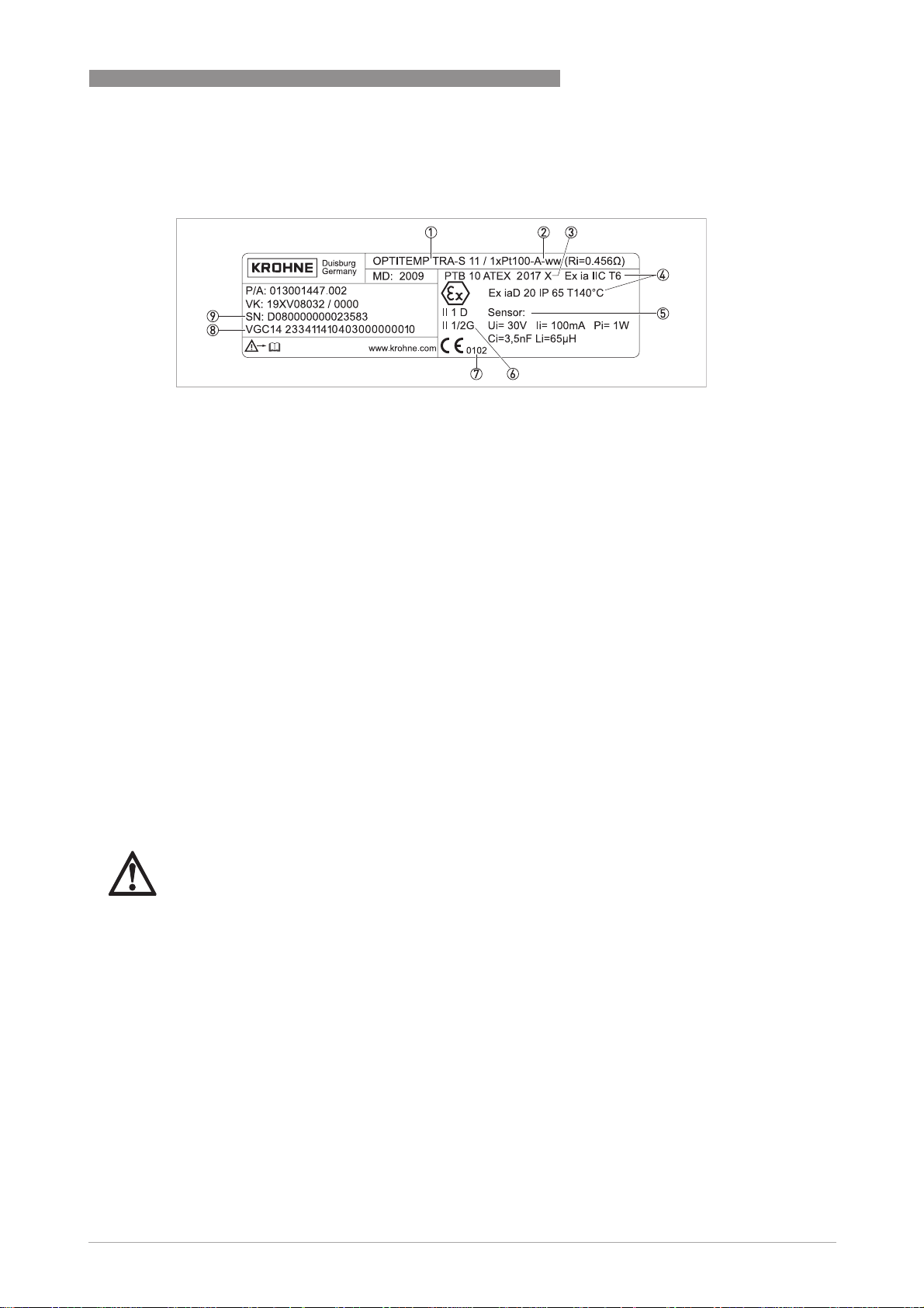
2.3 Marking
1 Type designation
2 Sensor designation
3 Number of the EC Type Test Certificate
4 Ex-marking for gas and dust
5 Electrical sensor values (this information is different if a transmitter is used as the transmitter values then apply)
6 Equipment group and category for gas and dust
7 Identification number of the notified body as per Directive 94/95, Appendix IV
8 VGC key
9 Unique serial number
DEVICE DESCRIPTION 2
2.4 Flammable products
Atmospheric conditions
An explosive atmosphere is a mixture of air and flammable gases, vapours, mists or dusts under
atmospheric conditions. It is defined by the following values:
= -20...+60°C / -4...+140°Fand P
T
atm
Outside of this range, no key data are available as to ignition behaviour for most mixtures.
Operating conditions
Outside of atmospheric conditions you cannot apply explosion protection according to Directive
94/9/EC (ATEX) – regardless of the zone assignment - due to the lack of key safety data.
DANGER!
The operator is responsible for ensuring that the industrial thermometers are operated safely
as regards the temperature and pressure of the products used. Include the thermometer
assembly in the periodic pressure tests of the system when operating with flammable products.
= 0.8...1.1 bar / 11.6...15.9 psi
atm
www.krohne.com10/2010 - 4001087001 - Ex AD OPTITEMP TRA/TCA R02 en
7
Page 8

2 DEVICE DESCRIPTION
2.5 Equipment category
Industrial thermometers are designed for use in zone 0 in category II 1 G, for use in zone 20 in
category II 1 D. In category II 1/2 G all thermometers have a separator (thermowell) which
separates zone 0 and zone 1.
INFORMATION!
Definition of Zone 0 according to EN 1127-1:
An area with a constant or long-term or frequent explosive atmosphere made up of a mixture of
flammable substances in the form of gas, vapours or mist.
For more information see the chapter entitled "Flammable products".
INFORMATION!
Definition of Zone 20 according to EN 61241-0:
An area with a constant or long-term or frequent explosive atmosphere in the form of a cloud of
flammable dust in air.
INFORMATION!
Definition of a device with separator as per EN 60079-26:
Devices which are installed in the wall to an area requiring EPL Ga or which are part of this wall
and contain electrical circuits which do not meet the requirements of the Ga protection level,
must, at minimum, comply with one of the protection types that an EPL Gb offers. In addition,
they must feature an integrated mechanical separator to separate the device's electrical circuits
from the area requiring EPL Ga.
OPTITEMP TRA/TCA
For further information refer to
Flammable products
on page 7.
8
www.krohne.com 10/2010 - 4001087001 - Ex AD OPTITEMP TRA/TCA R02 en
Page 9

OPTITEMP TRA/TCA
DEVICE DESCRIPTION 2
2.6 Protection types
2.6.1 Protection type with zone separator for gas hazard areas
In protection type "intrinsic safety" the industrial thermometer meets the requirements of
EN 60079-11. The explosion protection is guaranteed because the current and voltage are
limited so that ignitable energy cannot occur.
If zone 0 and zone 1 are separated as per EN 60079-26, this will ensure that a thermowell is
fitted properly. In such cases the thermometer marking is:
II 1/2G Ex ia IIC T6
II 1/2G Ex ia IIC T6
II 1/2G Ex ia IIC T6II 1/2G Ex ia IIC T6
Components of the Ex marking and what they mean
II
II Group II explosion protection
IIII
1/2
1/2 Equipment category 1/2
1/21/2
GGGG Gas explosion protection
Ex ia
Ex ia Intrinsically safe equipment
Ex iaEx ia
IIC
IIC Gas groups IIA, IIB, IIC
IICIIC
T6
T6 Temperature classes T6...T1
T6T6
2.6.2 Type of protection for gas hazard areas
In protection type "intrinsic safety" the industrial thermometer meets the requirements of
EN 60079-11. The explosion protection is guaranteed because the current and voltage are
limited so that ignitable energy cannot occur. In such cases the thermometer marking is:
II 1G Ex ia IIC T6
II 1G Ex ia IIC T6
II 1G Ex ia IIC T6II 1G Ex ia IIC T6
Components of the Ex marking and what they mean
II
II Group II explosion protection
IIII
1111 Equipment category 1
GGGG Gas explosion protection
Ex ia
Ex ia Intrinsically safe equipment
Ex iaEx ia
IIC
IIC Gas groups IIA, IIB, IIC
IICIIC
T6
T6 Temperature classes T6...T1
T6T6
www.krohne.com10/2010 - 4001087001 - Ex AD OPTITEMP TRA/TCA R02 en
9
Page 10
2 DEVICE DESCRIPTION
2.6.3 Type of protection for dust hazard areas
In protection type "Protection through instrinsic safety" the industrial thermometer meets the
requirements of EN 61241-11. The dust protection is guaranteed by housing which provides
appropriate protection against penetration by dust. Current and voltage are also limited so that
ignitable energy cannot occur. All thermometers with these features have the following
marking:
II 1D Ex iaD 20 IP65 T140
II 1D Ex iaD 20 IP65 T140°C
II 1D Ex iaD 20 IP65 T140II 1D Ex iaD 20 IP65 T140
Components of the Ex marking and what they mean
II
II Group II explosion protection
IIII
1111 Equipment category 1
DDDD Dust explosion protection
Ex ia D
Ex ia D Dust protection type intrinsic safety "iaD"
Ex ia DEx ia D
20
20 Use in zone 20
2020
IP65
IP65 Foreign bodies and water pollution control
IP65IP65
T140
T140°C
C Maximum surface temperature of industrial thermometer without dust coating at ambient
T140T140
CC
temperature 100°C / 212°F and product temperature 100°C / 212°F
C
CC
OPTITEMP TRA/TCA
DANGER!
As the TxA-P14 model does not have a thermowell, you must allow for a higher maximum
surface temperature! The marking is therefore:
II 1D Ex iaD 20 IP65 T175
II 1D Ex iaD 20 IP65 T175°C
II 1D Ex iaD 20 IP65 T175II 1D Ex iaD 20 IP65 T175
C
CC
Components of the Ex marking and what they mean (TxA-P14)
II
II Group II explosion protection
IIII
1111 Equipment category 1
DDDD Dust explosion protection
Ex ia D
Ex ia D Dust protection type intrinsic safety "iaD"
Ex ia DEx ia D
20
20 Use in zone 20
2020
IP65
IP65 Foreign bodies and water pollution control
IP65IP65
T175
T175°C
C Maximum surface temperature of industrial thermometer without dust coating at ambient
T175T175
CC
temperature 100°C / 212°F and product temperature 100°C / 212°F
10
www.krohne.com 10/2010 - 4001087001 - Ex AD OPTITEMP TRA/TCA R02 en
Page 11

OPTITEMP TRA/TCA
2.7 Temperature classes
The permitted ambient temperature range of the industrial thermometer without temperature
transmitter on the measuring insert ("head-mounted transmitter") is:
= -40...+100°C / -40...+212°F
T
amb
DANGER!
If you are using an industrial thermometer with head-mounted transmitter, refer to the Exdocumentation of the temperature transmitter for the permitted maximum values for the
ambient temperature.
Due to the influence of the product temperature, no fixed temperature class is assigned to
industrial thermometers. The temperature class of the devices is instead a function of the
following parameters:
DEVICE DESCRIPTION 2
• Present product temperature (T
• Maximum value of sensor output of connected temperature transmitter (P
• Maximum permitted temperature at the process connection of the measuring point (T
• Surface temperature of the sensor (T
The classification for the respective model is outlined in the following subchapters.
)
M
)
O
)
P
)
O
WARNING!
The maximum permitted product temperatures and process connection temperatures in the
tables of the following subchapters are only valid if you observe the following points:
•
The industrial thermometer has been installed in accordance with the assembly instructions
in these supplementary Ex instructions and the manual.
•
There is no additional thermal radiation at the measuring point (solar radiation, adjacent
equipment) which could heat up the industrial thermometer causing the maximum permitted
ambient temperature to be exceeded.
•
There is no additional convection from the container wall or adjacent pipes which could heat
up the industrial thermometer and cause the maximum permitted ambient temperature to be
exceeded.
•
The connection head is adequately ventilated.
•
All insulation measures only include the pipes, never the components of the industrial
thermometer.
www.krohne.com10/2010 - 4001087001 - Ex AD OPTITEMP TRA/TCA R02 en
11
Page 12

2 DEVICE DESCRIPTION
2.7.1 Maximum permitted product temperature
DANGER!
Regardless of the temperature class the various measuring inserts have the following lower
limit values for the product temperature (T
•
TC 100: -40°C/ -40°F
•
TR 100: -200°C / -328°F
Maximum permitted product temperature [°C]
M
OPTITEMP TRA/TCA
):
Temperature
class
T1 450 436 432 425 402 391 383 380 365
T2 300 286 282 275 252 241 233 230 215
T3 200 191 187 180 157 146 138 135 120
T4 135 126 122 115 92 81 73 70 55
T5 100 91 87 80 57 46 - - -
T6 85 76 72 65 42 - - - -
T
in [°C] P
o
≤
0
50 mW
P0 ≤
100 mW
P0 ≤
200 mW
P0 ≤
500 mW
P0 ≤
650 mW
P0 ≤
750 mW
P0 ≤
800 mW
P0 ≤
1000 mW
Maximum permitted product temperature [°F]
Temperature
class
T1 842 816 809 797 755 735 721 716 689
T2 572 546 539 527 485 465 451 446 419
T3 392 375 368 356 314 294 280 275 248
T4 275 258 251 238 197 177 163 158 131
T5 212 195 188 176 134 114 - - -
T6 185 168 161 149 107 - - - -
T
in [°F] P
o
≤
0
50 mW
P0 ≤
100 mW
P0 ≤
200 mW
P0 ≤
500 mW
P0 ≤
650 mW
P0 ≤
750 mW
P0 ≤
800 mW
P0 ≤
1000 mW
12
www.krohne.com 10/2010 - 4001087001 - Ex AD OPTITEMP TRA/TCA R02 en
Page 13
OPTITEMP TRA/TCA
DEVICE DESCRIPTION 2
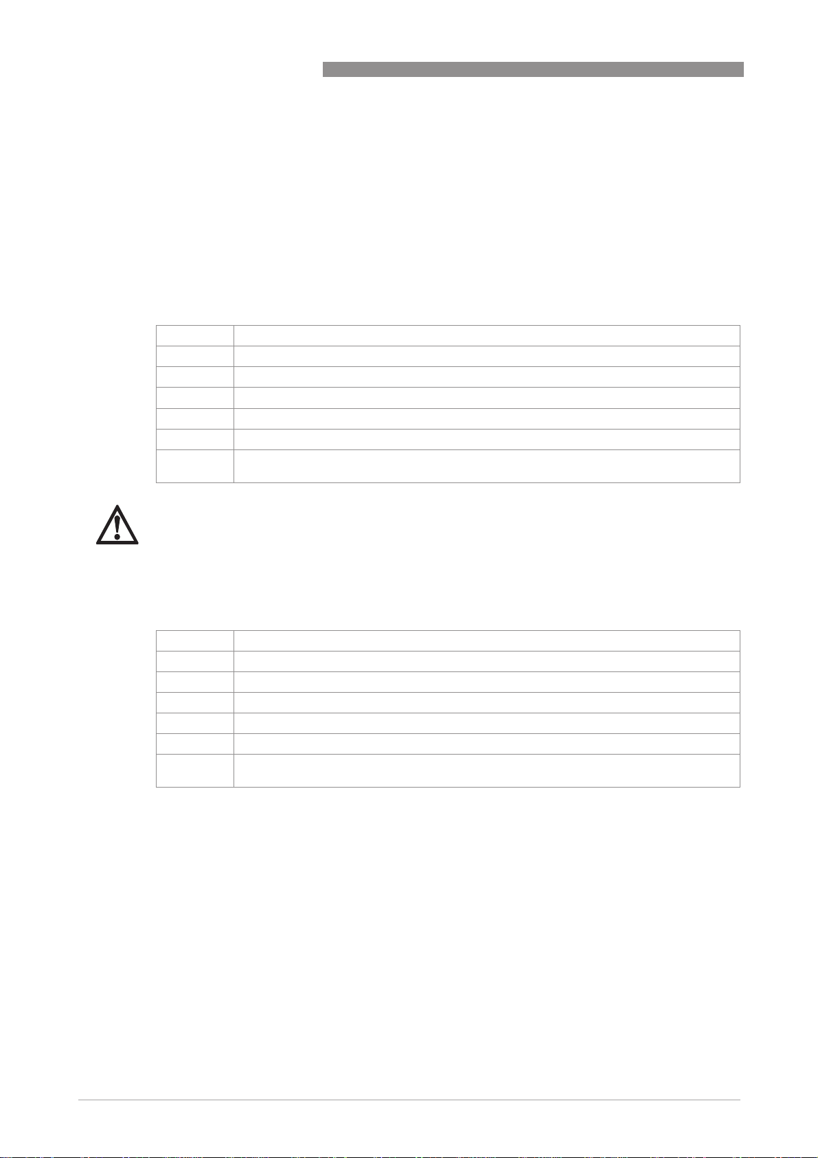
2.7.2 Temperature at process connection (without temperature transmitter)
DANGER!
The maximum permitted temperature at the process connection for all industrial thermometers
°
C/ 752ºF.
is 400
Maximum permitted temperature at process connection for thermometers without temperature
transmitter in [°C]
Thermometer models T
TxA-S11, threaded thermometer, neck pipe length ≤ 80mm 182 155 127 100
TxA-S12/41, threaded thermometer, neck pipe length ≥ 80mm 400 400 312 100
TxA-P10/40, insert thermometer with thermowell TxA-P10,
neck pipe length ≤ 80mm
TxA-P10/40, insert thermometer with thermowell, neck pipe
length ≥ 80mm
TxA-P14, insert thermometer without thermowell, neck pipe
length ≤ 80mm
TxA-P14, insert thermometer without thermowell, neck pipe
length ≥ 80mm
TxA-F13/42, flange thermometer, neck pipe length ≥ 80mm 400 400 339 100
= 40ºC
a
323 248 174 100
400 400 290 100
323 248 174 100
400 400 290 100
a
T
= 60ºC
T
= 80ºC Ta = 100ºC
a
Maximum permitted temperature at process connection for thermometers without temperature
transmitter in [°F]
Thermometer models T
TxA-S11, threaded thermometer, neck pipe length ≤ 80mm 361 311 261 212
TxA-S12/41, threaded thermometer, neck pipe length ≥ 80mm 752 752 594 212
TxA-P10/40, insert thermometer with thermowell TxA-P10,
neck pipe length ≤ 80mm
TxA-P10/40, insert thermometer with thermowell, neck pipe
length ≥ 80mm
TxA-P14, insert thermometer without thermowell, neck pipe
length ≤ 80mm
TxA-P14, insert thermometer without thermowell, neck pipe
length ≥ 80mm
TxA-F13/42, flange thermometer, neck pipe length ≥ 80mm 752 752 643 212
= 104ºF Ta = 140ºF Ta = 176ºF Ta = 212ºF
a
613 479 345 212
752 752 554 212
613 479 345 212
752 752 554 212
www.krohne.com10/2010 - 4001087001 - Ex AD OPTITEMP TRA/TCA R02 en
13
Page 14

2 DEVICE DESCRIPTION
Temperature at process connection without temperature transmitter
1 Maximum permitted temperature at the process connection ( Tp)
2 Ambient temperature at the measuring point (T
3 TxA-P14, insert thermometer without thermowell; TxA-P10, insert thermometer with thermowell; TxA-S12/41,
threaded thermometer; TxA-F13/42, flange thermometer; neck pipe length in each case ≥ 80 mm
4 TxA-P14, insert thermometer without thermowell; TxA-P10, insert thermometer with thermowell; neck pipe length in
each case ≤ 80 mm / 3.1
5 TxA-S11, threaded thermometer, neck pipe length ≤ 80 mm / 3.15"
OPTITEMP TRA/TCA
)
a
14
www.krohne.com 10/2010 - 4001087001 - Ex AD OPTITEMP TRA/TCA R02 en
Page 15

OPTITEMP TRA/TCA
DEVICE DESCRIPTION 2
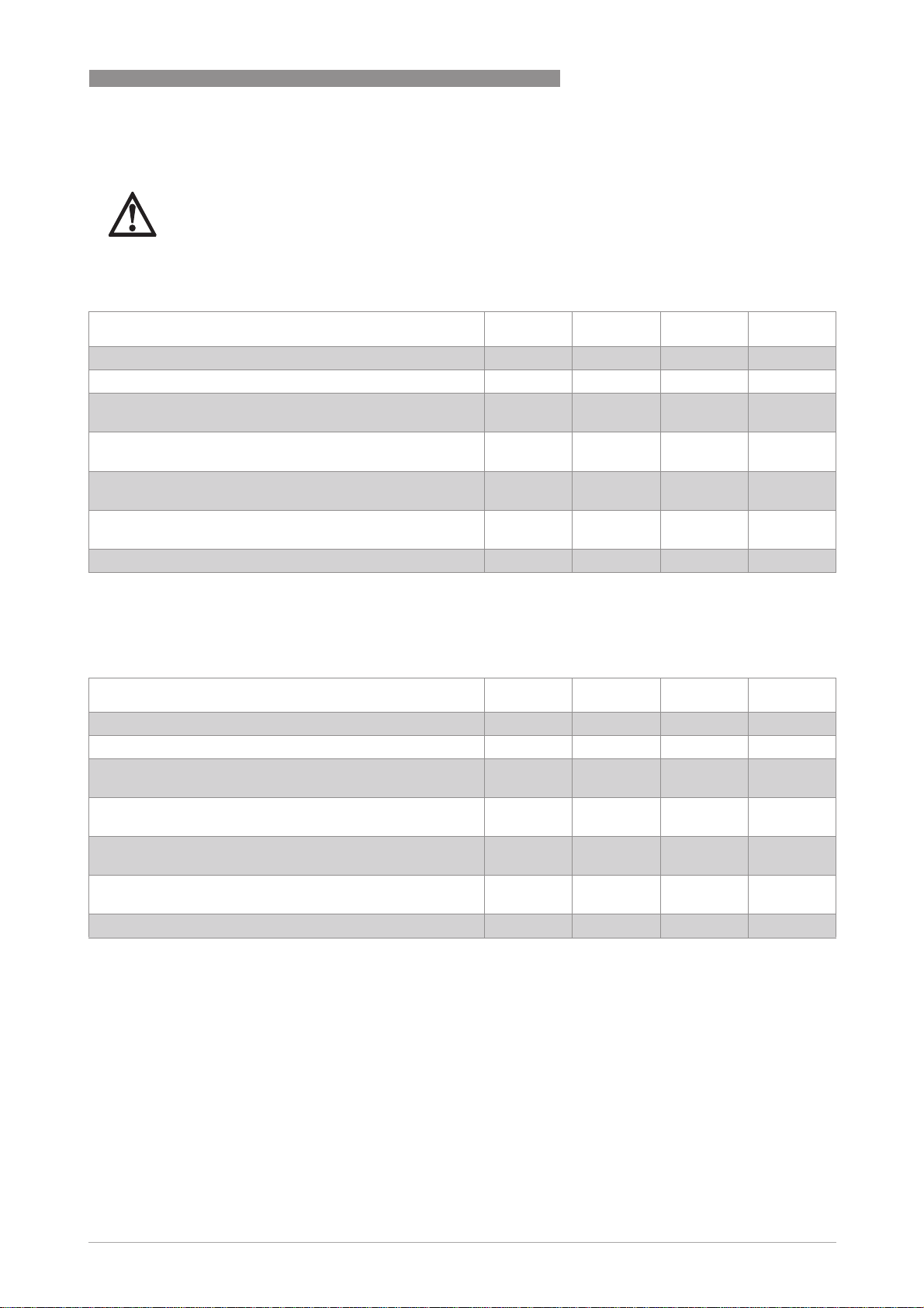
2.7.3 Temperature at process connection (with temperature transmitter)
DANGER!
The maximum permitted temperature at the process connection for all industrial thermometers
= 400°C / 752ºF. The maximum permitted ambient temperature is Ta=85°C / 185°F.
is T
P
Maximum permitted temperature at process connection for thermometers with temperature
transmitter in [°C]
Thermometer models T
TxA-S11, threaded thermometer, neck pipe length ≤ 80mm 135 107 86 80
TxA-S12/41, threaded thermometer, neck pipe length ≥ 80mm 400 292 133 80
TxA-P10/40, insert thermometer with thermowell TxA-P10,
neck pipe length ≤ 80mm
TxA-P10/40, insert thermometer with thermowell, neck pipe
length ≥ 80mm
TxA-P14, insert thermometer without thermowell, neck pipe
length ≤ 80mm
TxA-P14, insert thermometer without thermowell, neck pipe
length ≥ 80mm
TxA-F13/42, flange thermometer, neck pipe length ≥ 80mm 400 319 139 80
= 40ºC Ta = 60ºC Ta = 75ºC Ta = 80ºC
a
228 154 98 80
400 270 127 80
228 154 98 80
400 270 127 80
Maximum permitted temperature at process connection for thermometers with temperature
transmitter in [°F]
Thermometer models T
TxA-S11, threaded thermometer, neck pipe length ≤ 80mm 275 225 188 176
TxA-S12/41, threaded thermometer, neck pipe length ≥ 80mm 752 558 271 176
TxA-P10/40, insert thermometer with thermowell TxA-P10,
neck pipe length ≤ 80mm
TxA-P10/40, insert thermometer with thermowell, neck pipe
length ≥ 80mm
TxA-P14, insert thermometer without thermowell, neck pipe
length ≤ 80mm
TxA-P14, insert thermometer without thermowell, neck pipe
length ≥ 80mm
TxA-F13/42, flange thermometer, neck pipe length ≥ 80mm 752 607 283 176
= 104ºF Ta = 140ºF Ta = 167ºF Ta = 176ºF
a
443 309 209 176
752 518 261 176
443 309 209 176
752 518 261 176
www.krohne.com10/2010 - 4001087001 - Ex AD OPTITEMP TRA/TCA R02 en
15
Page 16

2 DEVICE DESCRIPTION
Temperature at process connection with temperature transmitter
1 Maximum permitted temperature at the process connection ( Tp)
2 Ambient temperature at the measuring point (T
3 TxA-P14, insert thermometer without thermowell; TxA-P10, insert thermometer with thermowell; TxA-S12/41,
threaded thermometer; TxA-F13/42, flange thermometer; neck pipe length in each case ≥ 80 mm
4 TxA-P14, insert thermometer without thermowell; TxA-P10, insert thermometer with thermowell; neck pipe length in
each case ≤ 80 mm / 3.15"
5 TxA-S11, threaded thermometer, neck pipe length ≤ 80 mm / 3.15"
OPTITEMP TRA/TCA
)
a
16
www.krohne.com 10/2010 - 4001087001 - Ex AD OPTITEMP TRA/TCA R02 en
Page 17

OPTITEMP TRA/TCA
DEVICE DESCRIPTION 2
2.7.4 Temperature at process connection (with temperature transmitter, classes T5 and
T6)
As special restrictions apply to temperature classes T5 and T6, you must heed the information
about the maximum ambient temperature in the temperature transmitter documentation.
Calculate the maximum permitted temperature at the process connection for all thermometers
with a temperature transmitter in temperature classes T5 and T6 as follows:
DANGER!
Always refer to your temperature transmitter documentation for the maximum permitted
ambient temperature of the temperature transmitter (T
1 TP = process connection temperature
2 k = coupling factor of thermometer versions (see table later in this subchapter)
= ambient temperature around the temperature transmitter (see transmitter documentation)
3 T
aTT
4 T
= ambient temperature at the measuring point
a
aTT
).
DANGER!
In order to prevent injury and material damage, always observe the limit values of the assigned
temperature class. For further information refer to Maximum permitted product temperature on
page 12
Coupling factors of the thermometer models
Thermometer model Coupling factor [k]
TxA-S11, threaded thermometer, neck pipe length ≤ 80mm 0.42
TxA-S12/41, threaded thermometer, neck pipe length ≥ 80mm 0.086
TxA-P10/40, insert thermometer with thermowell TxA-P10, neck pipe
length ≤ 80mm
TxA-P10/40, insert thermometer with thermowell, neck pipe length
≥ 80mm
TxA-P14, insert thermometer without thermowell, neck pipe length
≤ 80mm
TxA-P14, insert thermometer without thermowell, neck pipe length
≥ 80mm
TxA-F13/42, flange thermometer, neck pipe length ≥ 80mm 0.077
0.212
0.095
0.212
0.095
www.krohne.com10/2010 - 4001087001 - Ex AD OPTITEMP TRA/TCA R02 en
17
Page 18

2 DEVICE DESCRIPTION
OPTITEMP TRA/TCA
2.7.5 Temperature at process connection for thermometers with connecting cable
DANGER!
The maximum permitted temperature at the process connection for all industrial thermometers
= 400°C / 752ºF. The maximum permitted ambient temperature is Ta=70°C / 158°F. Always
is T
P
refer to the table below!
DANGER!
Always refer to the tables below. Always use heat-resistant connecting cables if the temperature
at the process connection exceeds the values in the tables below.
Maximum permitted temperature at process connection for thermometers with connecting cable
in [°C]
Thermometer models T
TxA-S11, threaded thermometer, neck pipe length ≤ 80mm 99 78 71 65
TxA-S12/41, threaded thermometer, neck pipe length ≥ 80mm 330 171 118 65
TxA-P10/40, insert thermometer with thermowell TxA-P10,
neck pipe length ≤ 80mm
TxA-P10/40, insert thermometer with thermowell, neck pipe
length ≥ 80mm
TxA-P14, insert thermometer without thermowell, neck pipe
length ≤ 80mm
TxA-P14, insert thermometer without thermowell, neck pipe
length ≥ 80mm
TxA-F13/42, flange thermometer, neck pipe length ≥ 80mm 364 184 124 65
= 40ºC Ta = 55ºC Ta = 60ºC Ta = 65ºC
a
157 102 83 65
303 160 112 65
157 102 83 65
303 160 112 65
Maximum permitted temperature at process connection for thermometers with connecting cable
in [°F]
Thermometer models T
TxA-S11, threaded thermometer, neck pipe length ≤ 80mm 211 173 161 149
TxA-S12/41, threaded thermometer, neck pipe length ≥ 80mm 627 340 244 149
TxA-P10/40, insert thermometer with thermowell TxA-P10,
neck pipe length ≤ 80mm
TxA-P10/40, insert thermometer with thermowell, neck pipe
length ≥ 80mm
TxA-P14, insert thermometer without thermowell, neck pipe
length ≤ 80mm
TxA-P14, insert thermometer without thermowell, neck pipe
length ≥ 80mm
TxA-F13/42, flange thermometer, neck pipe length ≥ 80mm 688 364 256 149
= 104ºF Ta = 131ºF Ta = 140ºF Ta = 149ºF
a
316 215 182 149
577 320 234 149
316 215 182 149
577 320 234 149
18
www.krohne.com 10/2010 - 4001087001 - Ex AD OPTITEMP TRA/TCA R02 en
Page 19

OPTITEMP TRA/TCA
Temperature at process connection for thermometers with connecting cable
1 Maximum permitted temperature at process connection ( Tp)
2 Ambient temperature at measuring point (T
3 TxA-P14, insert thermometer without thermowell; TxA-P10, insert thermometer with thermowell; TxA-S12/41,
threaded thermometer; TxA-F13/42, flange thermometer; neck pipe length in each case ≥ 80 mm / 3.15"
4 TxA-P14, insert thermometer without thermowell; TxA-P10, insert thermometer with thermowell; neck pipe length in
each case ≤ 80 mm / 3.15"
5 TxA-S11, threaded thermometer, neck pipe length ≤ 80 mm / 3.15"
DEVICE DESCRIPTION 2
)
a
www.krohne.com10/2010 - 4001087001 - Ex AD OPTITEMP TRA/TCA R02 en
19
Page 20

2 DEVICE DESCRIPTION
2.8 Electrical data
DANGER!
Connect the sensor circuit of an industrial thermometer only to intrinsically safe circuits as well
as separate transmitters certified as intrinsically safe or zener barriers. Observe the following
maximum values when connecting a measuring insert without temperature transmitter:
•
Ui =30V
•
Ii = 140 mA
•
Pi =1.0W
DANGER!
When connecting a thermometer to an electricity supply please observe the maximum values for
the effective capacities and inductances in the following table:
OPTITEMP TRA/TCA
Sensor length
up to 5 m / 16.4 ft up to 30 m / 98.4 ft
Ci= [nF] L
TR100 with Pt100 wire wound 3.5 65 21 390
TC100 type K 2.5 25 14 150
TC100 type J 2 48.5 11.5 289.5
= [µH] C
i
= [nF] L
i
= [µH]
i
DANGER!
Always observe the maximum values of the transmitter used with industrial thermometers
featuring a measuring insert with head-mounted transmitter. These maximum values can be
found on the transmitter nameplate. The sensor output P
is one of the the deciding factors
o
when assigning to a temperature class . For further information refer to Temperature classes
on page 11
.
20
www.krohne.com 10/2010 - 4001087001 - Ex AD OPTITEMP TRA/TCA R02 en
Page 21

OPTITEMP TRA/TCA
INSTALLATION 3
3.1 Selecting the right thermometer and calculating limit values
DANGER!
In order to prevent injury and material damage, always ensure that the process conditions do not
exceed the permitted limit values of the thermometer. Ask yourself the following questions
when planning a measuring point:
•
What are the temperatures (ambient temperature, product temperature, process connection
temperature) at the measuring point?
•
Do the process conditions necessitate heat-resistant feed lines?
•
Which industrial thermometer model would you like to use with which process connection?
•
Which type of sensor would you like to use?
Answering the above questions will help you deduce the following parameters and necessary
device properties:
• Whether or not you need a temperature transmitter
• Sensor output P
• Product temperature T
• Ambient temperature T
• Process connection temperature at the measuring point T
0
M
a
P
INFORMATION!
The temperature at the process connection of an industrial thermometer depends on how the
device is installed. The diagram below shows possible installations (T
is the point at which the
P
temperature at the process connection is measured):
Possible installations
www.krohne.com10/2010 - 4001087001 - Ex AD OPTITEMP TRA/TCA R02 en
21
Page 22

3 INSTALLATION
Once you have calculated the specified parameters and device properties, you must determine
the maximum permitted temperatures for your specific measuring point in three steps. Use the
tables in the previous subchapters to do this:
OPTITEMP TRA/TCA
• Determine the maximum permitted product temperature ( refer to
product temperature
on page 12).
Maximum permitted
• Determine the maximum permitted temperature at the process connection ( refer to
Temperature at process connection (without temperature transmitter)
Temperature at process connection (with temperature transmitter)
Temperature at process connection (with temperature transmitter, classes T5 and T6)
on page 13, refer to
on page 15 or refer to
on
page 17).
• Find out whether the thermometer requires a heat-resistant connecting cable; if so ensure
that the connecting cable can withstand the process conditions ( refer to
process connection for thermometers with connecting cable
on page 18).
Temperature at
Example: Determining the maximum permitted temperatures
This example is based on a TxA-F13 thermometer with head-mounted transmitter. It has the
following features and is subjected to the following process conditions:
• Length of neck pipe: min. 80 mm / 3.15"
• Maximum ambient temperature of transmitter: 85°C / 185°F
• Sensor output: P
• Ambient temperature at measuring point: T
• Product temperature: T
• Temperature at process connection: T
= 500 mW
o
M
= 70°C / 158°F
=40°C / 104°F
a
= 50°C / 122°F
P
Step 1: Calculate the maximum product temperature
• Refer to the table with the maximum permitted product temperatures ( refer to
permitted product temperature
on page 12).
• Look along the header of the table until you come to the column with your sensor output P
this case: 500 mW).
• Look down this column and find the product temperature at your measuring point (in this case:
70°C / 158°F).
• If you can't find this figure, always look at the next figure up.
Maximum
o
(in
i The maximum permitted product temperature is 92°C / 198°F and the temperature class is
T4.
22
www.krohne.com 10/2010 - 4001087001 - Ex AD OPTITEMP TRA/TCA R02 en
Page 23

OPTITEMP TRA/TCA
Step 2: Calculate the maximum permitted temperature at the process connection
• You must always calculate the highest permitted temperature at the process connection for
temperature classes T5 and T6 ( refer to
temperature transmitter, classes T5 and T6)
subchapter and omit the following steps.
• For all temperature classes except T5 and T6 refer to the tables with the maximum permitted
temperatures at the process connection; these also differentiate between thermometers with
and without a temperature transmitter ( refer to
temperature transmitter)
temperature transmitter)
• Find the model of thermometer used with the right neck pipe length in the first column of the
table (in this case: TxA-F13, neck pipe ≥ 80 mm / 3.15").
• Keep going to the right until you reach the column with the right ambient temperature T
this case: 40°C / 104°F).
i The maximum permitted temperature at the process connection is T
Step 3: Calculate the maximum permitted temperature at the process connection with
a thermometer connecting cable
• Refer to the table with the maximum permitted temperatures at the process connection with a
thermometer connecting cable refer to
thermometers with connecting cable
• Calculate the maximum permitted temperature as explained above ("step 2").
i The maximum permitted temperature at the process connection for a thermometer with
connecting cable is T
Temperature at process connection (with
on page 13, refer to
on page 15).
Temperature at process connection for
on page 18).
= 364°C / 687°F.
P
INSTALLATION 3
on page 17); therefore go directly to the specified
Temperature at process connection (without
Temperature at process connection (with
(in
a
= 400°C/ 752°F.
P
In this example the selected industrial thermometer is suitable for the specified process
conditions having checked all the maximum permitted temperatures. It falls into temperature
class T4.
www.krohne.com10/2010 - 4001087001 - Ex AD OPTITEMP TRA/TCA R02 en
23
Page 24

3 INSTALLATION
If the process conditions at your measuring point are outside of the values in the tables used in
the example above, you will have to use charts. These can be found in the subchapters below
following the tables. The charts also include less common temperatures.
The following sample chart shows you how to calculate the temperature at the process
connection at an ambient temperature T
• Find the ambient temperature at your measuring point along the X-axis (in this case: 60°C/
140°F).
• From this point trace straight up until you reach the temperature curve of your thermometer.
• From this intersection, move horizontally to the left until you reach the Y-axis.
• At the intersection with the Y-axis read off the temperature at the process connection (in this
case: 108°C / 226°F).
=60°C / 140°F:
a
OPTITEMP TRA/TCA
Example: Calculating the temperature at the process connection (T
1 Maximum permitted temperature at process connection ( Tp)
2 Ambient temperature at the measuring point (T
3 TxA-P14, insert thermometer without thermowell; TxA-P10, insert thermometer with thermowell; TxA-S12/41,
threaded thermometer; TxA-F13/42, flange thermometer; neck pipe length in each case ≥ 80 mm / 3.15"
4 TxA-P14, insert thermometer without thermowell; TxA-P10, insert thermometer with thermowell; neck pipe length in
each case ≤ 80 mm / 3.15"
5 TxA-S11, threaded thermometer, neck pipe length ≤ 80 mm / 3.15"
)
a
=85°C/ 185°F)
a
24
www.krohne.com 10/2010 - 4001087001 - Ex AD OPTITEMP TRA/TCA R02 en
Page 25

OPTITEMP TRA/TCA
3.2 Assembly
DANGER!
The manufacturer is not liable for any damage or injuries resulting from improper use or use
other than the intended purpose. This applies in particular to hazards due to insufficient
corrosion resistance and suitability of the materials in contact with products.
DANGER!
Installation and setup must be carried out according to the applicable installation standards (e.g.
EN 60079-14) by qualified personnel trained in explosion protection. Observe the information
contained in the manuals and the supplementary instructions. Assembly must always comply
with the following requirements:
•
There are no external forces on the thermometer assembly.
•
The device is accessible for any necessary visual inspections and can be viewed from all
sides.
•
The nameplate is clearly visible.
•
All seals are fit for purpose.
INSTALLATION 3
Installing an industrial thermometer with flange or thread connection
• Ensure that you use a seal suitable for the dimensions of the process connection (flange or
thread) and the requirements of the measuring point.
• Align the seal precisely (for thermometers with flange connection this applies to the flange
surface of the connection nozzle).
• Carefully lower the thermometer into the tank or the pipe.
• Observe all the relevant regulations and in particular the right torques and tighten the flange
screws or the thread connection.
www.krohne.com10/2010 - 4001087001 - Ex AD OPTITEMP TRA/TCA R02 en
25
Page 26

4 ELECTRICAL CONNECTIONS
4.1 General notes
DANGER!
In order to prevent injury and material damage, always take heed of the information about
temperatures at the process connection before connecting an industrial thermometer to an
electricity supply ( on page 18
Ensure that all connecting cables conform to the valid installation standards (e.g. EN 60079-
•
14) and withstand the maximum operating temperature.
•
Adjust the outer diameter of the connecting cables to the sealing range of the cable entries.
•
Securely lay the connecting cables and sufficiently protect them against damage.
•
Securely connect all the cores not in use with the ground potential of the explosive area or
carefully insulate them from each other and from ground (test voltage ≥ 500V
Industrial thermometers are connected to an electricity supply by connecting the sensor circuit
in the connection head to the interchangeable measuring insert.
DANGER!
Also refer to the transmitter's Ex manual for all industrial thermometers with an explosionproof transmitter.
). In addition, always observe the following points:
OPTITEMP TRA/TCA
).
eff
4.2 Power supply
The supply voltage of an industrial thermometer specifically refers to the supply voltage of the
measuring insert (for further information refer to
DANGER!
If you are operating the measuring insert together with a transmitter, pay attention to the details
of the power supply in the Ex documentation of the transmitter used. Also observe the maximum
values of the sensor circuit.
Electrical data
on page 20).
26
www.krohne.com 10/2010 - 4001087001 - Ex AD OPTITEMP TRA/TCA R02 en
Page 27

OPTITEMP TRA/TCA
4.3 Inputs / Outputs
The electrical connection of an industrial thermometer depends on the type of measuring insert
used. The manufacturer offers measuring inserts with two different sensor types, either with
Pt100 resistor (TR 100) or with thermocouple (TC 100).
4.3.1 Pt100 measuring inserts
A measuring insert with a Pt RTD is connected according to DIN EN 60751 in three different
wiring variants (from left to right: 2, 3 and 4 wire switch):
TR 100: Wiring (simple design)
ELECTRICAL CONNECTIONS 4
1 white
2 red
4.3.2 Thermocouple measuring inserts
Wiring of a thermocouple measuring insert is done in accordance with DIN EN 60584.
TC 100: Wiring (simple design)
www.krohne.com10/2010 - 4001087001 - Ex AD OPTITEMP TRA/TCA R02 en
27
Page 28

4 ELECTRICAL CONNECTIONS
4.4 Grounding and equipotential bonding
DANGER!
In order to prevent injury and material damage, always observe the following points regarding
grounding and equipotential bonding:
•
Always include the thermometer and its measuring insert as per EN 60079-14 in the
equipotential bonding of the installation site (when installed correctly, the fixing screws
guarantee this).
•
If the thermometer is not connected to a grounded metal pipe system or a container through
the process connection, you must include it in the equipotential bonding of the explosive area.
•
The connection for equipotential bonding is via the PA terminals or the process connection.
•
If there is a cable shield you must ground it according to EN 60079-14. A terminal in the
connection head means that the cable shield can be grounded by the shortest route.
The manufacturer's measuring insert connections withstand a test voltage of 500 VAC to earth.
OPTITEMP TRA/TCA
28
www.krohne.com 10/2010 - 4001087001 - Ex AD OPTITEMP TRA/TCA R02 en
Page 29

OPTITEMP TRA/TCA
5.1 Starting up for the first time
DANGER!
To prevent injury and material damage, only operate industrial thermometers under the
following conditions:
•
The equipment was installed and connected in accordance with the manufacturer's
instructions.
•
At the operator's request, a test was conducted prior to start-up to ensure the correct
installation and connection.
•
The check prior to start-up was in compliance with the national regulations for checks before
start-up.
5.2 Operation
DANGER!
To avoid injury and material damage, only operate the measuring inserts under the following
conditions:
OPERATION 5
•
Temperatures, pressures and electrical limit values are in the manufacturer's specified
range.
•
The equipment parts necessary for safety are effective in the long run, never disable them
during operation!
•
When using flammable products, the thermowell must be included in the periodic pressure
tests of the system.
You can open the connection head when live (thanks to the "intrinsic safety" protection type) even
in explosive areas to work on the electrical connections for measuring and setting purposes (e.g.
to configure a temperature transmitter):
CAUTION!
When using the thermometer, and in particular after work to the connection head, ensure that it
is closed properly. Otherwise the degree of IP protection is not guaranteed.
www.krohne.com10/2010 - 4001087001 - Ex AD OPTITEMP TRA/TCA R02 en
29
Page 30

6 SERVICE
6.1 Maintenance
DANGER!
Maintenance measures of a safety-relevant nature within the meaning of explosion protection
may only be carried out by the manufacturer, his authorised representative or under the
supervision of authorised inspectors.
For systems in explosive areas, regular tests are required in order to maintain the proper
condition. The manufacturer recommends the following maintenance measures:
• Check the housing, the cable entries and the feed lines for corrosion and/or damage.
• Check the process connection and the piping connections for leakage.
• Check the entire thermometer for dust deposits.
6.2 Dismantling
You can replace a separately certified intrinsically safe temperature transmitter or measuring
insert with an identical device from the manufacturer:
OPTITEMP TRA/TCA
DANGER!
In order to prevent injury and material damage when replacing components of the industrial
thermometer, always observe the following points:
•
To avoid electric shock, dismantle the measuring insert when it is de-energized where
possible. If this is not possible, the basic conditions for intrinsic safety (e.g. no grounding or
connection of different intrinsically safe circuits to one another) must be observed during
dismantling.
•
So as not to damage the cover of the connection head, only open it using a suitable tool (e.g. a
screwdriver).
•
When replacing both a separately certified intrinsically safe temperature transmitter and a
separately certified intrinsically safe measuring insert with an identical device from the
manufacturer, always refer to the Ex documentation for the devices. Ensure that the
construction is the same by checking the nameplates.
30
www.krohne.com 10/2010 - 4001087001 - Ex AD OPTITEMP TRA/TCA R02 en
Page 31

OPTITEMP TRA/TCA
As well as replacing individual components, it is also possible to replace the entire
thermometer, however you as operator have sole responsibility for this:
DANGER!
In order to prevent injury or material damage when replacing components of the industrial
thermometer, always observe the following points:
•
Before dismantling the electrical connecting lines of the device, ensure that all the cables
leading to the measuring insert are de-energised themselves and to the reference potential
of the explosive area. This also applies to equipotential bonding conductors (PA).
•
All the relevant process controls or containers must be depressurized before dismantling the
thermowell.
•
If the process cables or the container contain products that are harmful to the environment
or to health, implement the appropriate safety measures before dismantling the thermowell.
•
Replace all the seals when reinstalling the device in the process cable or container.
SERVICE 6
www.krohne.com10/2010 - 4001087001 - Ex AD OPTITEMP TRA/TCA R02 en
31
Page 32

KROHNE product overview
• Electromagnetic flowmeters
• Variable area flowmeters
• Ultrasonic flowmeters
• Mass flowmeters
• Vortex flowmeters
• Flow controllers
• Level meters
• Temperature meters
• Pressure meters
• Analysis products
• Measuring systems for the oil and gas industry
• Measuring systems for sea-going tankers
Head Office KROHNE Messtechnik GmbH
Ludwig-Krohne-Str. 5
D-47058 Duisburg (Germany)
Tel.:+49 (0)203 301 0
Fax:+49 (0)203 301 10389
info@krohne.de
© KROHNE 10/2010 - 4001087001 - Ex AD OPTITEMP TRA/TCA R02 en - Subject to change without notice.
The current list of all KROHNE contacts and addresses can be found at:
www.krohne.com
 Loading...