

Page 1
Capaflux IFM 5080 K-CAP
Electromagnetic Flowmeter
... non-contact process flow measurment
from 0.05 µS/cm electrical conductivity
● Ceramic measuring tube,
dimensionally stable,
vacuum resistant
● Optimum flow shaping
and unimpeded tube
cross-section
● Outstanding accuracy
● Non-wetted electrodes
GR
©
KROHNE 03/2002 7.02422.22.00
Variable area flowmeters
Vortex flowmeters
Flow controllers
Electromagnetic flowmeters
Ultrasonic flowmeters
Mass flowmeters
Level measuring instruments
Communications technology
Engineering systems & solutions
Switches, counters, displays and recorders
Heat metering
Pressure and temperature
Page 2
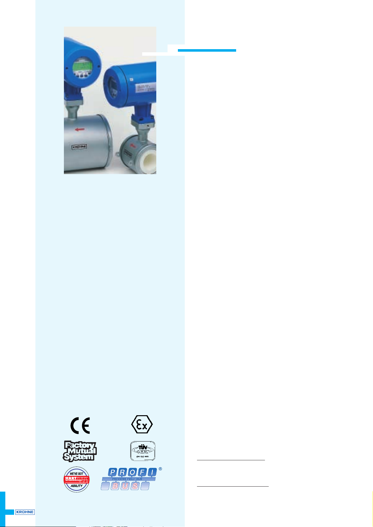
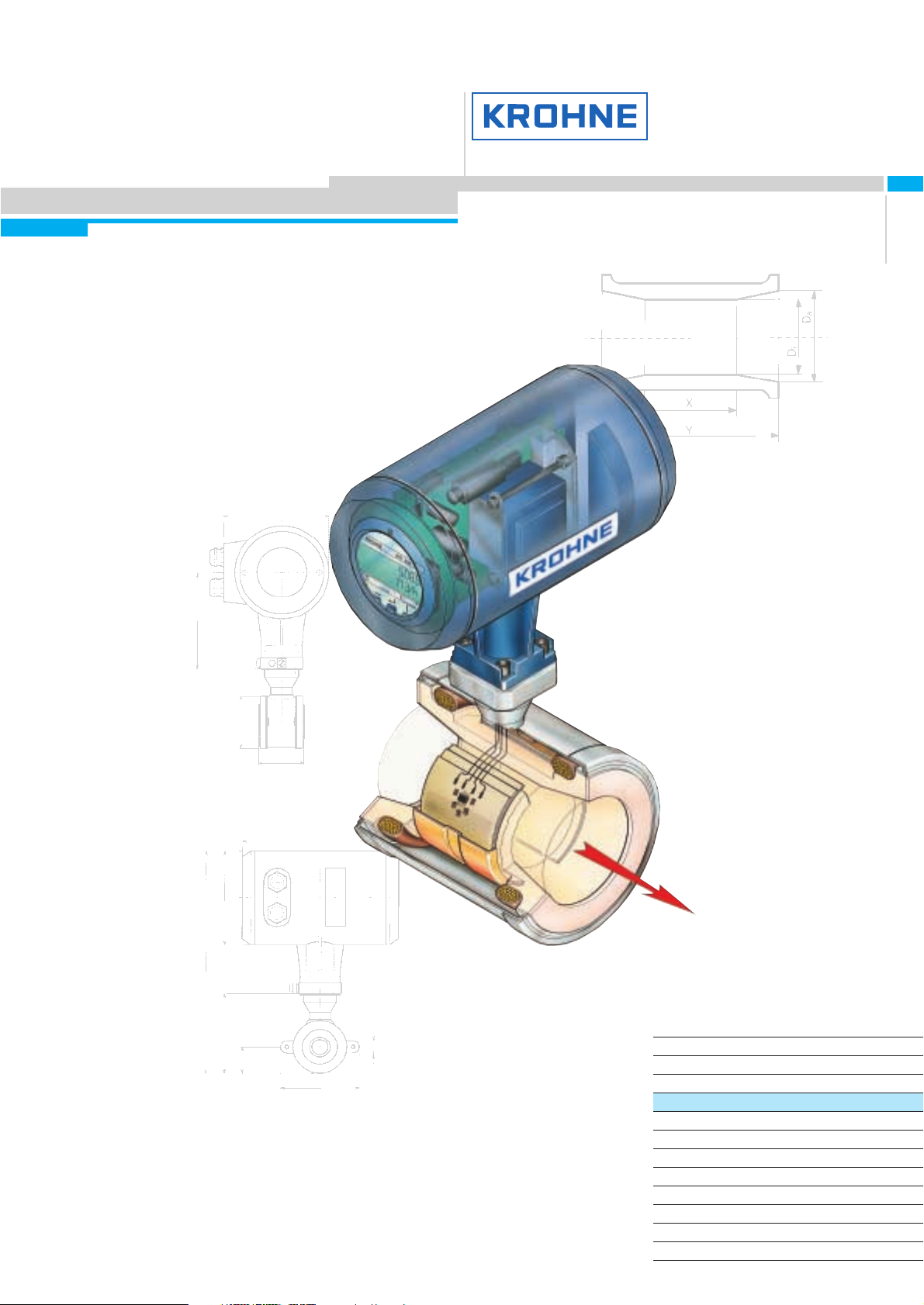
Capaflux IFM 5080 K-CAP
Electromagnetic Flowmeter
... non-contact process flow measurment
from 0.05 µS/cm electrical conductivity
non-contact flow measurement
no electrodes
easy to specify
unimpeded flow cross-sectional area
optimum flow shaping
resistant to abrasion
ceramic measuring tube
dimensionally stable vacuum-resistant
outstanding accuracy
Special advantages
● capacitive electrodes for non-contact measurement.
● the measuring section is resistant to abrasion from even high solids
contents.
● the ceramic measuring tube is dimensionally stable and vacuum-
resistant.
● the special shape of the measuring tube helps to optimize the flow
profile, even with minimum pressure drop, refer to diagram on
page 3.
● the measuring error is less than 0.5% of the measured value.
● the integral design ensures easy installation, safe and reliable
operation.
● the crevice-free measuring tube has no blind spots and conforms
to food requirements, the ceramic surface is ultrasmooth,
R
a
< 0,8 µm surface finish.
ATEX approval
Ex II 2 GD KEMA 01 ATEX 2232X
● CAPAFLUX IFM 5080 K/CAP-EEx:
EEx d IIC T6 … T4
EEx de IIC T6 … T4
● CAPAFLUX IFM 5080 K/CAP/i-EEx:
with outputs intrinsic safety
EEx d [ia] IIC T6 … T4
EEx de [ia] IIC T6 … T4
2
No restrictions ...
... through insulating products with a
film-forming tendency:
asphalt, latex suspensions
... through low electrical conductivity:
ultrahigh-purity water, alcohols,
glycerins, glycols
... through high solids contens:
fruit pieces, pulps, concrete
... for sterile processes:
chemical and food industries
... when used in hazardous areas:
ATEX approval
FM certification pending
... through electrode materials:
the capacitive electrodes are located
behind the ceramic tube, i.e. non-
contact measurement, no contact with
the process product.
Calibrated on EN 17 025
accredited calibration rigs,
accuracy of calibration better
than 99.97% of the measured value.
Page 3
CAPAFLUX 3
CAPAFLUX
Highlights
Capacitive electrodes for
non-contact measurement
Hazardous-duty version,
flameproof enclosure
Self-supporting ceramics
measuring tube,
press-fitted into stainless
steel housing
Meter sizes DN 25-100 or 1”-4”
Measuring error ≤ 0.5% of the measured value,
‘sandwich’ design, easy installation,
reliable and safe operation
Electrical conductivity ≥ 0.05 µS/cm,
e.g. ultrahigh-purity water, alcohols,
glycerols, glycols, etc.
Dimensionally stable measuring tube,
very good thermal and long-time stability,
no flow, creep and no abrasion,
as is usually the case with plastic liners
No crevices, no blind spots in the
measuring tube, conforms to food
standards, extremely smooth,
surface roughness < 0.8 µm
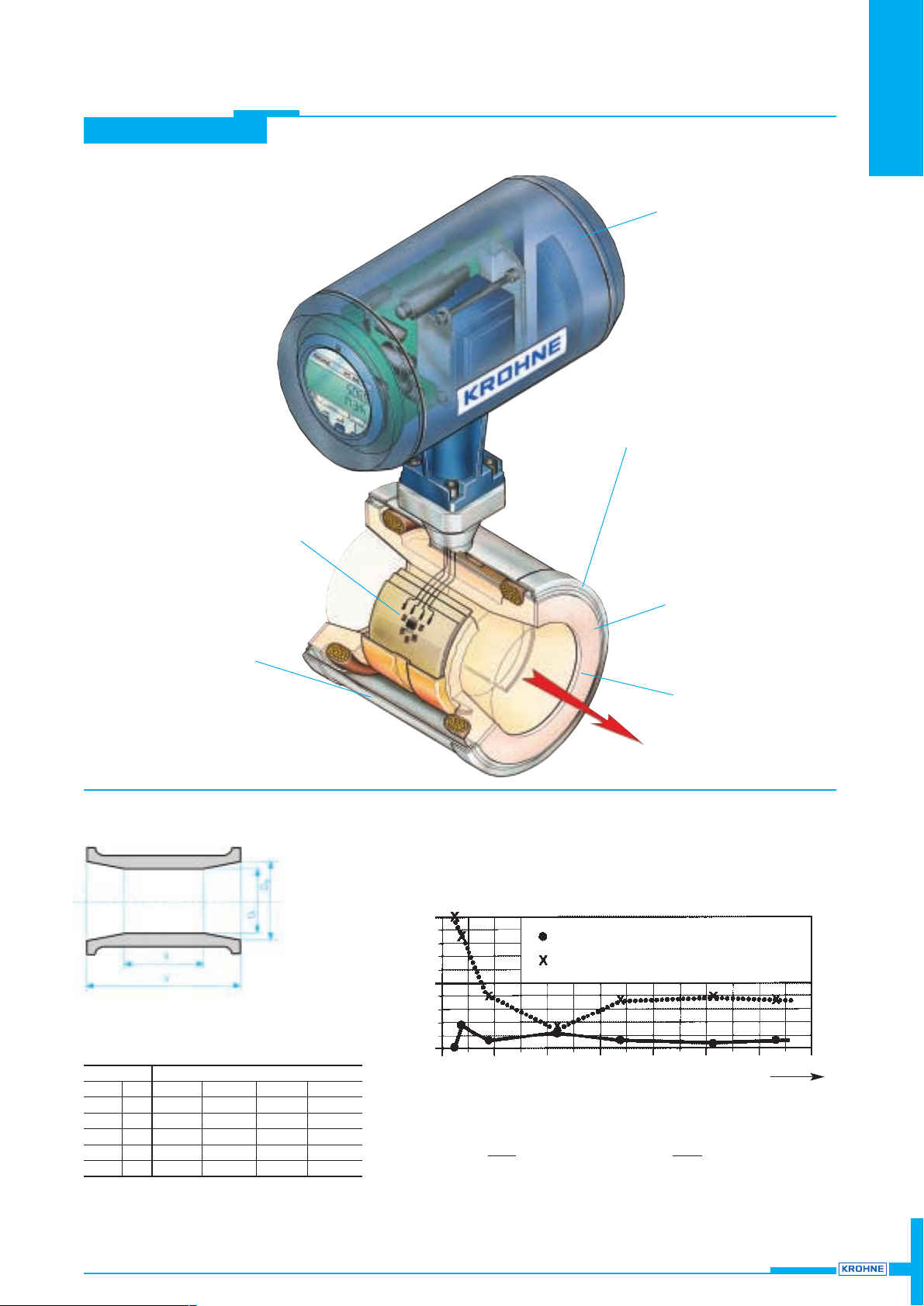
Design
Flow profile influence
(± SE) as % of measured value
Example for DN80 (3’’) with quarter bend, straight inlet run
5 × DN (= 400 mm = 16’’) from quarter bend to electrode plane
Pressure drop:
∆P =
ρ× v
2
(in mbar)
800
ρ = product density in (kg/m
3
)
v = flow velocity in m/s
∆P =
ρ× v
2
(in psig)
550
ρ = specific gravity (e.g. water = 1)
v = flow velocity in ft/s
0 0.5 1.0 1.5 2.0 2.5 3.0[m/s] 3.5
v
0 1.5 3.0 4.5 6.0 7.5 9.0 [ft/s]10.5
CAPAFLUX IFM 5080 K-CAP
Conventional flangeless flowmeter
1.0
±SE
[%]
0.5
0
Meter size Dimensions in mm (inches)
DN mm inches D
a
D
i
XY
25 1 24 (0.95) 20 (0.79) 26 (1.02) 55 (2.17)
40 11/2 37 (1.46) 30 (1.18) 36 (1.42) 80 (3.15)
50 2 49 (1.92) 40 (1.57) 51 (2.01) 100 (3.94)
80 3 78 (3.06) 60 (2.36) 70 (2.76) 150 (5.91)
100 4 98 (3.84) 80 (3.15) 103 (4.06) 200 (7.87)
Page 4

Measuring ranges and error limits
Meter size 1)Electrical conductivity Error limits
2)
Full-scale range Q
100%
0.05-0.2 µS/cm > 0.2 µS/cm in m3/h in US gal/min
mm inches (water (water v >1 m/s v≤ 1 m/s v = 0.3 m/s v= 1 m/s v= 12 m/s v= 1 ft/s v= 40 ft/s
1-2.5 µS/cm) >2.5 µS/cm) > 3 ft/s ≤3 ft/s (minimum) (maximum) (minimum) (maximum)
DN 25 1 0.5302 1.767 21.20 2.334 93.34
DN 40 11/
2
1.358 4.524 54.28 5.979 239.0
DN 50 2 2.121 7.069 84.82 9.339 373.5
DN 80 3 5.429 18.10 217.1 23.900 955.6
DN100 4 8.483 28.27 339.2 37.350 1493.0
Calibrated on EN 17025 accredited calibration rigs Reference conditions similar to EN 29104
by direct comparison of volumes Product water at 10 – 30°C / 50 – 86°F
Electrical conductivity > 300µS/cm
Power supply (rated voltage) U
N
(± 2%)
Ambient temperature 20 – 22°C / 68 – 71.6°F
Warm-up time 60min
Inlet/outlet runs 10 x DN / 2 x DN (DN = meter size)
Primary head properly grounded and centered
Current output same error limits as above, additionally ±10 µA
Reproducibility or repeatability 0.1 % of MV, minimum 1 mm/s / 0.04 inches/s at constant flow, measuring time > 100 s
External influences typical values maximum values
Ambient temperature
Pulse output 0.003% of MV (3) 0.01% of MV (3)
Current output 0.01% of MV (3) 0.025% of MV (3)
}
at 1K /1.8°F variation
P
ower supply <0.02% of MV 0.05% of MV at 10 % variation
Load
<0.01% of MV 0.02% of MV at max. permissible load, see pages 5 and 6
(3) All KROHNE signal converters undergo burn-in tests, duration minimum 20 hours at varying ambient temperatures
– 20 to + 60 °C / – 4 to + 140 °F. The tests are controlled by computers.
CAPAFLUX
CAPAFLUX
4
1) Where low electrical conductivities are concerned,
the meter size should be such that flow velocity
v < 1 m/s (< 3 ft/s).
2) Error limits for display,
pulse output, digital values
<±0.5%
of measured
value
<±5mm/s
<±0.20
inches/s
depending on
product and
application
condition, please
consult your local
KROHNE office
for all
applications
Dimensions and weights
● all dimensions in mm and (inches)
● without grounding rings: Dimension a incl. gaskets between primary head and pipe flanges
● with groundings rings: Dimension a + 10 mm or a + 0.4’’, incl. 2 gaskets between measuring tube and grounding rings and
2 between grounding rings and pipe flanges
Meter size Dimensions in mm and (inches) approx. weight
DN mm inches a b c d e Ø f Ø di in kg (lb)
25 1 58 (2.28) 302 (11.89) 113 (4.45) 34 (1.34) 102 (4.02) 68 (2.68) 20 (0.79) 3.9 (8.6)
40 11/283 (3.27) 318 (12.52) 129 (5.08) 42 (1.65) 117 (4.61) 83 (3.27) 30 (1.18) 4.7 (10.4)
50 2 103 (4.06) 336 (13.23) 147 (5.79) 51 (2.01) 135 (5.31) 101 (3.98) 40 (1.57) 5.2 (11.5)
80 3 153 (6.02) 368 (14.49) 179 (7.05) 67 (2.64) 167 (6.57) 133 (5.24) 60 (2.36) 7.7 (17.0)
100 4 203 (7.99) 392 (15.43) 203 (7.99) 79 (3.11) 192 (7.56) 158 (6.22) 80 (3.15) 11.1 (24.5)
136 (5.35’’)
128 (5.04’’)
dia. f
d
c
b
dia. di
dia. 122 (4.80’’)
208 (8.19’’)
e
a
Page 5

CAPAFLUX 5
CAPAFLUX
CAPPAFLUX Primary head
Meter size DN 25, 40, 50, 80, 100 and 1”, 11/2”, 2”, 3”, 4”, flangeless version
Operating data
Temperatures Ambient temperature Product temperature
– 25 to + 60°C / – 13 to + 140°F – 25 to + 60°C / – 13 to + 140°F
– 25 to + 40°C / – 13 to + 104°F – 25 to + 100 °C / – 13 to + 212°F
● non Ex : + 140°C/+284°F
for max. 30 min
● Ex version : + 115°C/+239°F
Pressure DN 25 – 80: 40 bar / 580 psig
DN 100: 16 bar / 230 psig (option 25 bar)
1” – 4”: 16 bar / 230 psig for 150 lb
1” – 3”: 40 bar / 580 psig for 300 lb
}
pipe
4”: 25 bar / 360 psig for 300 lb
flanges
Vacuum 0 mbar abs. / 0 psia
Temperature change
Temperature rising in 10 minutes: ∆ T = 125 °C, or 257 °F
for sudden change: ∆ T = 120 °C, or 248 °F
Temperature falling in 10 minutes: ∆ T = 100 °C, or 212 °F
for sudden change: ∆ T = 180 °C, or 176 °F
Insulation class of field coils H
Electrode design capacitive signal pickup,
electrodes not in contact with the product
Protection category (IEC 529 / EN 60 529) IP 67 equivalent to NEMA 6
Items included with supply Standard Option
for pipe flanges DN 25 – 80 / PN 40
DN 100 / PN 16 DN 100 / PN 25
1” – 4” / 150 lb 1” – 4” / 300 lb
Centering material yes –
Stud bolts steel stainless steel
Grounding rings – yes
Gaskets 2 (without grounding rings) 4 (with grounding rings)
Ex versions: European standard - EEx d IIC T6-T4
FM approval – in preparation
Materials
Measuring section
DN 25, 1” zirconium oxide, ZrO
2
DN 40 – 100, 11/2” – 4” fused aluminium oxid, 99.7 % Al2O
3
Housing (with polyurethane finish) stainless steel 1.4301 / SS 304 – AISI
Gask
ets Gylon 3500 (beige) gaskets (application range similar to that of PTFE),
optionally Chemotherm (graphite) gaskets
Grounding rings (option) stainless steel 1.4571/ SS 316 Ti – AISI, others on request
Centerin
g material
DN 25, 1” EPDM rings
DN 40 – 100, 1
1
/2” – 4” rubber sleeves
Stud bolts
steel electrogalvanized, optionally stainlees steel 1.4301 / SS 304 – AISI
Technical data
The responsibility as to the suitability, intended use and corrosion-resistance of the materials used in their
construction rests solely with the purchaser.
Page 6

CAPAFLUX
6 CAPAFLUX
IFC 090 K-CAP Signal converter
Versions
IFC 090 K/B (Standard) Basic version, without local display and control elements
IFC 090 K/D (Option) Display version, with local display and control elements
IFC 090 K/D-EEx Ex version with “Increased Safety” outputs
Interfaces (option) – HART®
– RS 485/PROFIBUS/FIELDBUS (switch-selectable add-on module)
Add-on equipment (option) CONFIG-Software and adapter for operator control via MS-DOS PC,
connection to internal IMoCom interface (equipment bus)
Current output
Function – all operating data configurable
– galvanically isolated from current output and all input circuits
– for active or passive mode
Current: fixed ranges 0 – 20mA and 4 – 20 mA
variable ranges for Q = 0% I0%= 0 – 16mA
for Q = 100% I
100%
= 4 – 20mA }adjustable in 1 mA increments
for Q > 100% I
max
= 22mA
Active mode max. 500 Ω load
Passive mode external voltage: 15 ... 20V DC 20 ... 32V DC
load: min ... max. 0 ... 500Ω 250 ... 750Ω
Error identification 0/ 22 mA and variable
Forward/reverse flow measurement direction identified via status output
Pulse output
Function – all operating data configurable
– galvanically isolated from all input and output circuits
– digital pulse division, interpulse period non-uniform, therefore if frequency
and cycle meters connected allow for minimum counting interval:
gate time, totalizer ≥
1000
P100% [Hz]
Active mode connection: electronic totalizers
voltage: approx. 15 V DC, from current output
load: I
max
< 23mA, operation without current output
load: I
max
< 3mA, operation with current output
Passive mode connection: electronic or electromechanical totalizers
voltage: external, U
ext
≤ 30 V DC/≤ 24 V AC
load: I
max
≤ 150 mA
Pulse width automatic: pulse duty cycle 1:1, max 1000 pulses/s = 1 kHz
variable: 10 ms – 2 s P
100%
[pulses/s] = f
max
[Hz] =
1
2 x pulse width
Forward/reverse flow measurement flow direction identified via status output
Status output (passive)
Function configurable as measuring range identification for BA mode,
indicator for flow direction, errors or trip point
Connection voltage: external, U
ext
≤ 30 V DC/≤ 24 V AC
load current: I
max
≤ 150 mA
Control input (passive)
Function – configurable for range change, totalizer reset, error reset,
set outputs to min. values or hold actual output values
– initiate function by “low” or “high” control signals
Control signals U
max
: 24 V AC 32 V DC (any polarity)
low: ≤ 1.4 V ≤ 2 V
high: ≥ 3 V ≥ 4 V
Output/input combinations I = current output P = pulse output S = status output C = control input
The following combinations can be set:
1) I P S
2) I P C
3) I C S
4) I S1 S2
5) I C1 C2
Time constant 0.2 – 99.9 s, adjustable in increments of 0.1 second
Low-flow cutoff
Cutoff “on” value: 1 – 19%
Cutoff “off” value: 2 – 20%
}
of Q
100%
,
adjustable in 1% increments
Page 7

7
CAPAFLUX
CAPAFLUX
Local display 3-field LCD
Display function actual flowrate, forward, reverse and sum totalizers (7-digit),
or 25-character bar graph with percentage indication and status messages
Units: Actual flowrate m
3
/h, liters, US gallons/min or user-defined unit, e.g. hecto-liters/day
Totalizer m
3
, liters, US gallons or user-defined unit, e.g. hecto-liters or US million gallons
(adjustable count duration up to overflow)
Language of plain texts English, German, French, others on request
Display: Top field 8-character, 7-segment numeral and sign display,
and symbols for key acknowledgement
Middle field 10-character, 14-segment text display
Bottom field 4 markers to identify display in measuring mode
Power supply 1. AC Version 2. AC Version AC/DC-Version
Standard Option Option
1. Rated voltage 230 / 240 V 200 V 24 V AC 24 V DC
Tolerance band 200 – 260 V 170 – 220 V 20 – 27 V AC 18 – 32 V DC
2. Rated voltage 115 / 120 V 100 V – –
Tolerance band 100 – 130 V 85 – 110 V – –
Frequency 48 – 63 Hz 48 – 63 Hz –
Power consumption (incl. primary head) approx. 10 VA approx. 10 VA approx. 8 W
When connected to functional extra-low voltage, 24 V, safety separation (PELV) is essential
(to VDE 0100 / VDE 0106 and IEC 364 / IEC 536 or equivalent national standard.)
Housing
Material die-cast aluminium with polyurethane finish
Ambient temperature – 25 to + 60°C (– 13 to + 140°F)
Protection category (IEC 529 / EN 60 529) IP 67, equivalent to NEMA 6
Electrical connection
binary outputs
and inputs
for
internal
use only
current output
PE 100 – 240 V AC (PE protective conductor)
FE 24 V AC/DC (FE functional ground)
B1 pulse output (P),
status output (S)
or control input (C)
B2 status output (S)
or control input (C)
Electrical connection in conformity with
VDE 0100 “Regulations gover-ning heavycurrent installations with mains voltages up
to 1000 V” or equivalent national standard.
If to be connected to a functional extra-low
voltage source (24 V), protective separation
in conformity with VDE 0100, Part 410, or
equivalent national standard, must be
ensured.
Current output (I)
Operating data of receiver instruments, outputs and inputs, see pages 6 and 7.
passive active passive passive
Pulse output (P)
status output (S)
Control input (C)
(not with
Ex version)
P
electronic
or electro-
mechanical
totalizer
S
e.g.
signal
indicator
 Loading...