

Page 1
04/02
Addition to the
Magnetic-inductive
flowmeters
ALTOFLUX
IFM 4080 K-EEx
IFM 4080 K/i-EEx
Compact flowmeter
installation and
operating
instructions
7.30917.31.00
Page 2

WARNING !
No changes may be made to the devices. Unauthorized changes
might affect the explosion safety of the devices.
These additional instructions are an extension to the Installation and Operating
Instructions and only applies for the EEx version of the IFM 4080 K or IFM 4080 K / i EEx magnetic-inductive compact flowmeter. All technical information described in the
Installation and Operating Instructions are applicable, when not specifically excluded
or replaced by the instructions in these additional instructions.
CONTENTS
1 SYSTEM COMPONENTS...............................................................................................................2
1.1 General information...................................................................................................................2
1.2 Primary head...............................................................................................................................3
1.3 IFC 090/…-EEx signal converter.............................................................................................3
1.3.1 Electronics compartment ........................................................................................................3
1.3.2 Terminal compartment...........................................................................................................3
1.4 Electronics unit ........................................................................................................................... 4
1.4.1 Regular IFC090-EEx electronics unit .....................................................................................4
1.4.2 IFC 090i-EEx unit with MODIS modules ................................................................................4
2 ELECTRICAL CONNECTION........................................................................................................5
2.1 Equipotential bonding system ..................................................................................................5
2.2 Regular IFC 090-EEx electronics unit....................................................................................5
2.3 MODIS version IFC 090i-EEx electronics unit......................................................................6
2.3.1 Connection diagrams MODIS ................................................................................................8
3 OPERATION OF THE SIGNAL CONVERTER.........................................................................14
4 SERVICE..........................................................................................................................................14
4.1 Replacement of electronics unit or power fuse(s) ..............................................................15
4.1.1 Replacement of electronics unit............................................................................................16
4.1.2 Replacement of power fuse(s)...............................................................................................17
4.1.3 Changing power supply voltage............................................................................................20
5 CONNECTING CABLES...............................................................................................................21
6 MAINTENANCE..............................................................................................................................21
7 CONNECTION DIAGRAM .............................................................................................................22
8 ORDERING INFORMATION.........................................................................................................23
8.1 Regular IFC 090-EEx electronics unit..................................................................................23
8.2 MODIS version IFC 090i-EEx electronics unit....................................................................23
9 DATA PLATES................................................................................................................................24
10DECLARATION OF CONFORMITY............................................................................................25
11EC-TYPE EXAMINATION CERTIFICATE.................................................................................26
Be sure to follow these instructions !
IMPORTANT !
• The prescriptions and regulations as well as the electrical data described in the
EC-type examination certificate must be obeyed.
• Beside the instructions for electrical installations in non-hazardous locations according
to the applicable national standard (equivalent of IEC 364, e.g. VDE 0100), especially
the regulations in EN 60079-14 "Electrical installations in hazardous locations" or
equivalent national standard (e.g. DIN VDE 0165) must be followed.
• Installation, establishment, utilization and maintenance are only allowed to be
executed by personnel with an education in explosion safety !
1
Page 3
1 SYSTEM COMPONENTS
1.1 General information
The Altoflux IFM 4080 K/…-EEx magnetic-inductive compact flowmeter is in accordance with
the European Directive 94/9 EC (ATEX 100a) and approved for hazardous classified
locations of Zone 1 and 2 by the KEMA conform to the European Standards of the EN 500xx
series. The IFM 4080 K/…-EEx has the following approval number.
KEMA 01 ATEX 2200 X
The compact flowmeter is available in two types, namely:
• IFM 4080 K-EEx regular explosion protected version;
• IFM 4080 K/i-EEx, MODIS version. This type has intrinsically safe signal output circuits,
which are provided by two on the IFC 090i-EEx electronics unit installed MODIS modules.
The regular IFM 4080 K-EEx compact flowmeter is designed for ambient temperatures in the
range of -20°C (special -40°C) up to +60°C, the MODIS version type IFM 4080 K/i-EEx is
rated for ambient temperatures from -20°C up to +60°C.
The allowed process liquid temperature is a.o. limited by the combustible atmosphere that
(possibly) surrounds the apparatus, which again is determined by the temperature class of
the atmosphere (first column of the tables). See table 1 and 2 below for details.
For dusts the second column of the two below listed tables is applicable.
Max. surface
class
(for gases)
T6 T85°C 75°C 70°C 70°C
T5 T100°C 95°C 90°C 75°C
T4 T135°C 130°C 115°C 75°C
T3 T180°C 150°C 115°C 75°C
class
(for gases)
T6 T85°C 70°C 70°C 70°C
T5 T100°C 85°C 85°C 85°C
T4 T135°C 120°C 120°C 115°C
T3 T180°C 180°C 180°C 115°C
Use heat-resistant cables above - - 50°C
Table 2: Temperature classification DN25…150 with PFA liner.
The IFM 4080 K/…-EEx flowmeter consists of the IFC 090/…-EEx signal converter unit,
which is screwed on top of the primary head (i.e. measuring unit). The compact flowmeter is
marked with one of the codes below, depending on the meter size:
temperature
(for dusts)
Table 1: Temperature classification DN200 and larger.
Max. surface
temperature
(for dusts)
Maximum process liquid temperatureTemperature
Ta ≤ 40°C Ta ≤ 50°C Ta ≤ 60°C
Maximum process liquid temperatureTemperature
Ta ≤ 40°C Ta ≤ 50°C Ta ≤ 60°C
• DN25-150: II 2GD EEx d [ib] IIC T6…T3 (EEx d terminal compartment) or
II 2GD EEx de [ib] IIC T6 …T3 (EEx e terminal compartment).
• DN200 and up: II 2GD EEx de [ib] IIC T6…T3 (both EEx d and EEx e
terminal compartment).
2
Page 4

In case of the MODIS version IFM 4080 K/i-EEx , the electronics unit of type IFC 090i-EEx is
provided with protective modules, which provide intrinsically safe output signals of category
"ia". The flowmeter is then marked with one of the following codes:
• DN25-150: II 2GD EEx d [ia] [ib] IIC T6…T3 (EEx d terminal compartment) or
II 2GD EEx de [ia] [ib] IIC T6…T3 (EEx e terminal compartment).
• DN200 and up: II 2GD EEx de [ia] [ib] IIC T6…T3. (both EEx d and EEx e
terminal compartment)
For details see the EC-type examination certificate in Section 11 of these instructions.
1.2 Primary head
The primary head is the measuring unit of the IFM 4080 K/…-EEx compact flowmeter and
contains two field coils (see table 3 for type of protection) and two electrodes in type of
protection intrinsic safety category "ib" according to EN 50020.
Meter size Type of protection
DN25 up to DN150
DN200 and larger
Housing: Flameproof enclosure "d" according to EN 50018
Electrodes: Intrinsic safety "ib" according to EN 50020
Field coils: Increased safety "e" according to EN 50019
Electrodes: Intrinsic safety "ib" according to EN 50020
Table 3: Types of protection of primary head.
NOTE:
The intrinsically safe electrode circuits of the IFM 4080K/…-EEx compact flowmeter are
only internal circuits and not accessible for the customer.
1.3 IFC 090/…-EEx signal converter
The IFC 090/…-EEx signal converter consists of a cylindrical housing of die-casted
aluminum, which has two separate compartments, divided from each other by an integrated
wall with casted flameproof terminal feed-through. The neck at the bottom of the housing
contains a flameproof cable feed-through. The signal converter housing is on both ends
closed by a cylindrical threaded cover with O-ring sealing. The housing has an ingress
protection degree of at least IP67 conform to EN 60529.
1.3.1 Electronics compartment
The electronics compartment accommodates the pre-certified IFC 090…-EEx electronics unit
with approval number PTB 98 ATEX 2012 U. The compartment is designed with type of
protection flameproof enclosure "d" according to EN 50018. It is closed by a flameproof
display cover with glass window.
1.3.2 Terminal compartment
The terminal compartment has seven terminals for connection of the power supply and signal
output circuits. Chapter 2 and 7 show the terminal arrangement for the regular and MODIS
version of the IFC 090/…-EEx signal converter. The terminal arrangement of the MODIS
version (i.e. IFC 090i-EEx) is shown in figure 4 on page 6. Two of the terminals are used for
connection of the non-intrinsically safe power supply and four terminals (marked with "*")
for the intrinsically safe, category "ia" signal outputs of the MODIS modules. The nonintrinsically and intrinsically safe terminals are separated from each other by a metal dividing
plate, which is screwed to the remaining (not connected) M4 terminal. The two non-
intrinsically safe power supply terminals are covered by an insulating plate.
3
Page 5
The terminal compartment (with standard type of protection increased safety "e") is standard
equipped with two ATEX approved "EEx e" cable glands. The terminal compartment can also
be provided as a flameproof enclosure "d", in which case ATEX approved "EEx d" cable
glands of size Pg13.5, Pg16 or M20x1.5 are either factory installed or must be installed by
the customer. For flameproof conduit systems, the terminal compartment must have type of
protection flameproof enclosure "d" according to EN 50018. The conduits must be sealed by
"EEx d" approved (within the ATEX 100a directive) sealing devices (i.e. stopping box) directly
at the conduit entrances of the as flameproof enclosure performed terminal compartment.
1.4 Electronics unit
The IFM 4080 K/…-EEx magnetic-inductive compact flowmeter can be equipped with the
regular IFC 090-EEx or with the IFC 090i-EEx electronics unit with intrinsically safe signal
outputs (i.e. MODIS version). The next subsections give a detailed description of these units.
1.4.1 Regular IFC090-EEx electronics unit
The IFC 090-EEx is used in the regular IFM 4080 K-EEx and can be equipped with one of
the following power supplies (depends on the area of application).
Power
Terminal Function Electrical data
supply
L
AC-versions
AC/DC-version
The IFC 090-EEx electronics unit is equipped with the following in-/output circuits. Terminals
B1, B⊥ and B2 can be configured as status or pulse outputs or as control inputs via the
software. See the table below for the electrical data of these in-/output circuits.
Terminals Description Nominal voltage Maximum current
I+, I
B1, B⊥ , B2
Pulse, status, control in-/outputs 32 V 150 mA
N
PE
1L½
0L½
FE
Table 4: Electrical data of power supply.
Current output 15 V 22 mA
Table 5: Electrical data of in-/output circuits.
1.4.2 IFC 090i-EEx unit with MODIS modules
The IFC 090i-EEx electronics unit is equipped with a pair of MODIS-modules (see page 8). It
is equipped with one of the following power supplies.
Live
Neutral
Protective Earth
Live
Neutral
Functional Earth
Un = 100/115/200/230 Vac -15/+10%
Pn = approx. 10 VA, Um = 253 V
Un = 24 V ac/dc
AC: -15/+10%, Pn=10 VA
DC: -25/+30%, Pn=8 W
Um = 253 V
Power supply Terminals Function Electrical data
L
AC-version
AC/DC-version
NOTE: The mains fuses for both electronics units are listed in Section 8 of this manual.
N
PE
1L½
0L½
FE
Table 6: Electrical data of IFC 090i-EEx electronics unit.
Live
Neutral
Protective Earth
Live
Neutral
Functional Earth
4
Un = 100…230 Vac –15%/+10%
Pn = 15 VA, Um = 253 V
Un = 24 Vac/dc
AC:-15%/+10% or 20.4…26.4 Vac
DC:-25%/+30% or 18…32 Vdc
Pn = 10 W, Um = 253 V
Page 6
2 ELECTRICAL CONNECTION
⊥
Ri ≤ 500
Ω
I+ I
mA
½
B1 B
B2
I ≤ 150 mA
U
ext
≤ 32Vdc/24 Vac
000
I ≤ 150 mA
indicator
2.1 Equipotential bonding system
The IFM 4080 K-EEx and IFM 4080 K / i-EEx flowmeters must always be incorporated into
the equipotential bonding system of the hazardous area. This connection can be achieved
through the PE/FE conductor connected to the PE terminal in the terminal compartment
(see figure 1) or through a separate PE conductor, cross sectional area at least 4 mm2,
connected to the external PE clamp, placed below the converter housing.
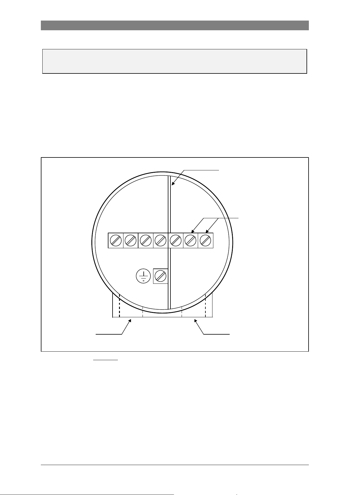
2.2 Regular IFC 090-EEx electronics unit
The field cables that enter the terminal compartment of the IFC 090-EEx signal converter unit
(i.e. power supply, current and binary outputs) are non-intrinsically safe. To connect external
devices to the signal output terminals, the wiring requirements for the type of protection of
the compartment (standard: increased safety "e", optional: flameproof "d") must be conform
to the international or national standard involved (e.g. EN 60079-14).
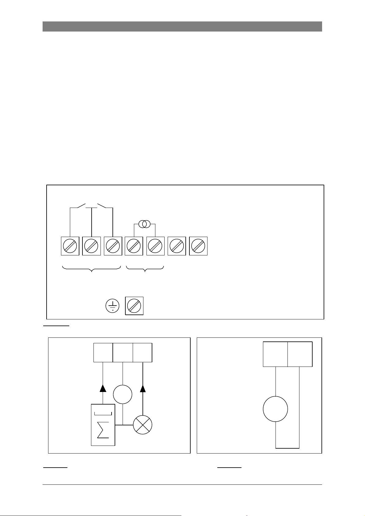
The terminal arrangement is shown by figure 1 below.
PULSE, STATUS OUTPUTS
RESP. CONTROL INPUTS
B1 B
BINARY CURRENT
OUTPUTS OUTPUT
Figure 1: Terminal arrangement in terminal compartment.
B2 I+ I L N (100…240Vac / 48…63 Hz)
U
L
PE (Protective Earth) terminal
FE (Functional Earth) terminal
ext
e.g. signal
½
L
(24Vac/dc)
½
+
_
Figure 2 Passive pulse/status output Figure 3 Active current output
5
Page 7
Note:
terminals
½
L N 100…240 Vac
The binary outputs (terminals B1, B⊥ and B2) can only be configured as passive outputs,
the current output (terminals I+ and I) can only be configured as active output.
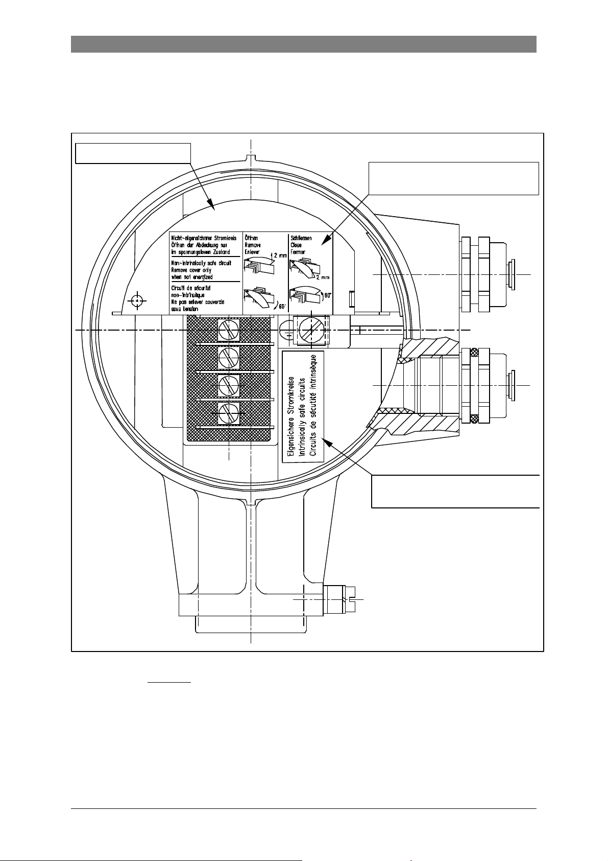
2.3 MODIS version IFC 090i-EEx electronics unit
The field cables of the non-intrinsically safe power supply and the intrinsically safe,
category "ia" signal outputs enter the terminal compartment of the IFC 090i-EEx signal
converter unit via two separate entrances. To connect external devices to the intrinsically
safe signal output terminals, the wiring requirements for their type of protection as well as of
the compartment (standard: increased safety "e", optional: flameproof enclosure "d") must be
conform to the international or national standard involved (e.g. EN 60079-14). Figure 4 below
shows the terminal arrangement inside the terminal compartment.
NC = not connected
Cable entrance for
intrinsically safe
signal cable
Connecting terminals
for intrinsically safe
signal in-/outputs
Metal dividing
plate IS / non-IS
Connecting
terminals for
non-intrinsically
safe power supply
NC 1L½0L
PE Protective Earth terminal
24 Vac/dc
Cable entrance for
non-intrinsically
safe power supply
cable
The non-intrinsically safe terminals for connection of the power supply (1L½ and 0L½) must
be connected according to the relevant standard code of practice for electrical apparatus
intended for use in potentially hazardous locations, type of protection Increased Safety "e" or
type of protection Flameproof Enclosure "d", depending on the type of protection of the
terminal compartment of the signal converter housing.
To gain access to the connection terminals of the power supply, the half-circular cover plate
of insulating material must be slightly lifted at one end and then rotated downwards, see the
instruction on the cover plate. After connection of the power supply cable, the half-circular
cover plate must be restored into its original position, so that the minimum clearances and
creepage distances towards the intrinsically safe signal in-/output terminals are maintained.
Figure 4: Terminal arrangement in terminal compartment.
6
Page 8
See for details figure 5 .
Insulating cover plate
Sticker with handling information
for insulating cover plate
Sticker indicating the intrinsically
safe signal in-/output circuits
Figure 5: Terminal compartment MODIS version IFC 090i-EEx.
7
Page 9
The PE (or FE) conductor must be connected to the press-fitted M5 clamp terminal marked
inside the terminal compartment. This conductor must be guided through the rectangular
opening in the metal dividing plate that separates the non-intrinsically safe power supply
terminals from the intrinsically safe signal in-/output terminals.
2.3.1 Connection diagrams MODIS
Section 7 shows the block diagram of the IFM 4080 K/ i…-EEx magnetic-inductive compact
flowmeter. The power supply (terminals 1L½, 0L½) is connected via cable B. The PE terminal
must be connected to the protective earth conductor of the mains supply.
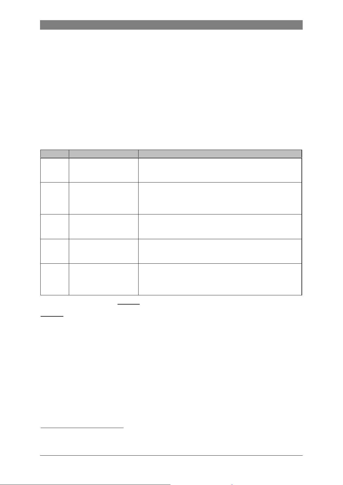
The IFC 090i-EEx electronics unit is provided with intrinsically safe signal in-/output
circuits due to the installed pair of MODIS modules in accordance with the table below.
Module Terminal designation Function / Intrisically safe maximum data
Current output (0/4-20 mA), passive
P-SA
FA-ST
F-PA D, D ⊥
F-FF D, D ⊥
DC-I
(see note)
I ⊥ , I
B1, B1⊥ or B2, B2 ⊥
I+, B1+
Table 7: Overview of MODIS modules.
Ui = 30 V, Ii = 250 mA, Pi = 1.0 W
Ci = 5 nF, Li ≈ 0
Pulse (frequency) output or status in-/output, all passive
The function can be set by software
Ui = 30 V, Ii = 250 mA, Pi = 1.0 W
Ci = 5 nF, Li ≈ 0
Fieldbus module, type Profibus system, passive
Ui = 30 V, Ii = 300 mA, Pi = 4.2 W
Ci = 5 nF, Li ≈ 0
Fieldbus module, type Fieldbus Foundation, passive
Ui = 30 V, Ii = 300 mA, Pi = 4.2 W
Ci = 5 nF, Li ≈ 0
Intrinsically safe voltage source for the passive module
P-SA or FA-ST, so that active operation is possible.
Uo = 23.5 V, Io = 98 mA, Po = 0.6 W
Co = 132 nF 1, Lo = 4 mH
NOTES:
• Besides the shown intrinsically safe maximum values for voltages and current -which are
based on certain fault conditions as prescribed by the standard EN 50 020 - the nominal
values for current and voltage must also be respected otherwise a proper funtioning of
the modules is not guaranteed! See table 8 for the nominal values.
• The active module DC-I is needed in the 24 Vac/dc power supply version to form an
active current or pulse output in combination with one of the passive modules P-SA or
FA-ST. Due to limited space it is not available for 100...230 Vac supply versions.
Table 9 shows the possible combinations of the installed MODIS modules for the 24 Vac/dc
power supply version of the IFC 090i-EEx and table 10 for the 100-230 Vac version.
1
When modules P-SA (or FA-ST) and DC-I are connected in series, the internal capacitance Ci of 5 nF must be
subtracted from the Co of 132 nF. So the data plate will list a Co of 127 nF.
8
Page 10

MODIS modul Nominal values for voltage and current
P-SA
(passive current output )
FA-ST
(frequency/pulse/status output
or control input)
DC-I
(active voltage source)
Table 8: Nominal voltage and current values for the MODIS modules
IFC 090i-EEx version Part No. MODIS modules Terminal designation
Ex-i1 2.11582.01.00 P-SA FA-ST I ⊥ I B1 B1⊥
Ex-i2 2.11582.03.00 P-SA F-PA I ⊥ I D D ⊥
Ex-i3 2.11582.02.00 P-SA DC-I I+ I
Ex-i4 2.11582.05.00 FA-ST F-PA B1 B1⊥ D D ⊥
Ex-i5 2.11582.06.00 FA-ST DC-I B1+ B1
Ex-i6 2.11582.07.00 FA-ST FA-ST B2 B2⊥ B1 B1 ⊥
Ex-i7 2.11582.08.00 P-SA F-FF
Ex-i8 2.11582.09.00 FA-ST F-FF B1 B1⊥ D D ⊥
Current: 4 .. 20 mA
Working voltage: 8 .. 30V
Voltage drop : 8V at 4mA
Working voltage: 6 .. 30V
Working current: < 110 mA
Voltage drop: in ON-state: < 2V at 110 mA
Leakage current in OFF-state: < 900 µA at 30V
Control input:
Input voltage LOW level: < 3V
Input voltage HIGH level: > 7V
Frequency range : 0 .. 12 KHz
Voltage: 20V
Current 30 mA
Internal resistance: 260
I ⊥
I D
D ⊥
Table 9 : IFC 090i-EEx 24 Vac/dc versions.
IFC 090i-EEx version Part No. MODIS modules Terminal designation
Ex-i1 2.12253.01.00 P-SA FA-ST I ⊥ I B1 B1⊥
Ex-i2 2.12253.02.00 P-SA F-PA I ⊥ I D D ⊥
Ex-i4 2.12253.03.00 FA-ST F-PA B1 B1⊥ D D ⊥
Ex-i6 2.12253.04.00 FA-ST FA-ST B2 B2⊥ B1 B1 ⊥
Ex-i7 2.12253.05.00 P-SA F-FF I ⊥ I D D ⊥
Ex-i8 2.12253.06.00 FA-ST F-FF B1 B1⊥ D D ⊥
Table 10: IFC 090i-EEx 100-230 Vac versions.
Due to mechanical and electrical limitations, only the in table 9 and 10 listed pairs of MODIS
modules are possible. The two modules each use two terminals of the bottom four terminals
of the flameproof terminal feed-through in the dividing wall between the electronics and
terminal compartment of the signal converter housing, except for the combination with
module DC-I (only applicable for 24 Vac/dc versions), where only two of the four terminals
are used. Interconnection of the two modules, P-SA and DC-I resp. FA-ST and DC-I is made
internally.
9
Page 11

The flameproof terminal feed-through has seven terminals in total, the top two terminals are
used for connection of the power supply, the third one is only used for mounting of a metal
dividing plate with insulating cover plate. The remaining four are used for the intrinsically safe
signal in-/output circuits of the installed MODIS modules.
The metal dividing plate and the insulating cover plate warrant the required separation
distances (i.e. clearances, creepage distances and distances through insulation) between the
non-intrinsically safe power supply terminals and the intrinsically safe signal in-/output
circuits. The insulating cover plate is provided with a sticker that contains important
instructions how to remove and re-install the cover plate and the conditions under which it
should be established ( circuits not live !).
IMPORTANT !
Carefully follow the instructions on the sticker that is glued on top of the insulating
cover plate, that covers the non-intrinsically safe power supply terminals !
For the connection diagrams of the intrinsically safe signal in-/outputs of the installed MODIS
modules in the IFC 090i-EEx electronics unit (see figure 6, 7 and 8 on the following pages). It
has to be noted that the intrinsically safe signal in-/outputs may only be connected to the
following listed apparatus' (registering devices like amp-meters, pulse counters, etc.):
• EEx-approved intrinsically safe apparatus;
• EEx-approved associated apparatus;
• Passive apparatus as defined in your national standard for installation of electrical
apparatus in hazardous locations (equivalent of EN 60079-14, e.g. DIN VDE 0165).
Other types of apparatus may only be connected to the intrinsically safe signal in-/outputs
through EEx-approved safety barriers, isolating interface units and the like. These barriers or
units are not depicted in the connection diagrams of figure 6, 7 and 8 for reasons of
readability. It is assumed that they are an integrated part of the registering devices or as
separate devices connected in series with them. The registering devices may only be
installed in the hazardous location if they also have a type of protection for explosion safety
according to the European Standards of the EN 500xx series, or if they are constructed as
prescribed in your standard national code of practice.
When the intrinsically safe signal in-/outputs are connected to other intrinsically safe or
associated apparatus, the maximum safety values (i.e. entity parameters) of all intrinsically
safe circuits have to be considered.
IMPORTANT !
The 100…230 Vac power supply versions of the IFC 090i-EEx signal converter electronics
unit with MODIS modules can only be equipped with passive outputs. The connection
diagrams in the following figures 6 through 8 with the numbers 1, 3, 6 ,8 and 10 are
therefore not applicable for the 100…230 Vac power supply versions.
10
Page 12

Figure 6: Connection diagrams 1 through 4 of the intrinsically safe signal in-/outputs.
11
Page 13

Figure 7: Connection diagrams 5 through 8 of the intrinsically safe signal in-/outputs.
12
Page 14

Figure 8: Connection diagrams 9 through 12 of the intrinsically safe signal in-/outputs.
13
Page 15

3 OPERATION OF THE SIGNAL CONVERTER
The IFM 4080 K / i-EEx compact flowmeters are always equipped with magnet sensors. In
that way is possible to change the settings of the converter with aid of the magnet-bar
without the necessity to open the flameproof converter housing in the hazardous area.
For the program functions and settings of the converter the standard Installation and
operating instructions have to be consulted. It must be noted that - depending on the
IFC090 i-EEx version installed - not all output/input functions are available.
Following menus do not apply for the IFC090 i-EEx versions Ex-i2 and Ex-i3:
(see also section 4.4. "Table of settable Functions" in the of the standard "Installation and
operating instructions" of the IFC090 K/F signal converter)
• 1.01 à VALUE P
• 1.06 Output/input B1
• 1.07 Output/input B2
Fct. Text Description and settings
1.00 OPERATION Operations menu
1.01 FULL SCALE ...
à VALUE P
1.06 Output/Input B1
1.07 Output/Input B2
1.06 PULS B1
1.06
1.07
1.06
1.07
3.00 INSTALL. Installation menu
3.02 FLOWMETER ...
3.07 HARDWARE
As a consequence, the chapters included in the standard Installations and operating
instructions, giving detailed descriptions of these menus, must be skipped.
STATUS B1
STATUS B2
CONTROL B1
CONTROL B2
à VALUE P
• 1.06 PULS B1
• 1.06 STATUS B1
• 1.07 STATUS B2
• 1.06 CONTROL B1
• 1.07 CONTROL B2
• 3.02 à VALUE P
• 3.07 HARDWARE
4 SERVICE
See section 8 or contact your (local) Krohne sales representative for the ordering information
of spare parts or replacements of IFC 090…-EEx electronics units and/or power fuses.
14
Page 16

4.1 Replacement of electronics unit or power fuse(s)
B
IMPORTANT !
The following instructions must be followed carefully, if the IFC 090/…-EEx signal
converter housing has to be opened respectively closed again !
Before opening:
♦ Make absolutely sure that there is no explosion hazard !
♦ Gas-free certificate !
♦ Make sure that all connecting cables are safely isolated from the power supply !
♦ Allow the prescribed waiting time to elapse before opening the housing:
20 minutes for temperature class T6
11 minutes for temperature class T5
When the instructions above are strictly followed, the cover (with glass window) of the
electronics compartment may be removed. First unscrew the recessed head screw of the
interlocking device by a hollow-head screw wrench size 3, until the cover can rotate freely.
Unscrew the cover with the special plastic wrench (black) that is supplied with the apparatus.
After opening:
♦ The copper earth strip at the back of the electronics unit must be securely screwed to the
housing (back-end of electronics compartment) by screw SE (see figure 9 below). The
electronics unit is screwed into the electronics compartment by two screws D . Before
screws SE and D can be accessed, the display unit must be removed via screws A.
♦ Before the cover is screwed back into the housing, the screw-thread must be clean and
well-greased with an acid and resin-free grease, e.g. silicone grease.
♦ Screw the cover as tight as possible into the housing by hand, until it cannot be opened by
hand anymore. Screw the recessed head screw of the interlocking device tight.
SE
Note:
Safe earth
connection
SE
C
Flat cable of display unit
Figure 9: IFC 090-EEx electronics unit after removal of display unit.
A
Power fuse in fuse-holder
D
Mains transformer
Signal converter housing
D
Power supply PC-board
A
15
Page 17

4.1.1 Replacement of electronics unit
A
A
Refer to the standard Installation and Operating Instructions for detailed information about
resetting and reprogramming the new electronics unit after replacement. The customer
specific data (like the value of the internal totalizer) are stored in DATAPROM IC-18, which
must be transferred from the "old" to the "new" electronics unit. See Section 8.7 of the
standard Installation and Operating Instructions for detailed information.
Figure 10: Display unit of IFC 090…-EEx.
Before commencing work, note the instructions in Section 3.1 ("Before opening").
Then continue as follows:
1. Remove the display cover of the electronics compartment.
2. Unscrew the two screws A of the display unit (see figure 10) and turn it carefully aside.
3. Disconnect the 2-pole field circuit connector (item B in figure 9) and the 3-pole electrode
circuit connector (item C). Also see figure 11 on the next page.
4. Unscrew the two mounting screws D of the electronics unit and screw SE, which fixes the
copper earth strip to the back of the housing. A screwdriver with a long shaft (≥ 200 mm)
is most suitable for unscrewing screw SE (e.g. screwdriver type Philips No. 2).
5. Carefully remove the electronics unit of the converter housing (see the remark below).
6. Check if the voltage setting (only applicable for AC power supplies) and power fuse rating
are correct on the new electronics unit. If necessary, change the voltage setting or
replace the power fuse (see section 3.1.3 resp. 3.1.2 of this manual).
7. Carefully insert the electronics unit (keep cables aside, see remark below). Then mount
the unit completely into the housing and fix the screws. First the two screws D, then
screw SE and reconnect the 2-pole field circuit connector B and the 3-pole electrode
circuit connector C to the right counter-plugs on the electronics unit (see also figure 9).
8. Finally screw the display unit back on the frame of the electronics via the two screws A.
9. Screw the cover of the electronics compartment back into the housing.
Note the instructions of section 3.1 ("After opening") during reassembling.
IMPORTANT !
Carefully keep the connecting cables of the field coil and electrode circuits to the side of
the housing, while removing respectively inserting the electronics unit into the signal
converter housing. This is to prevent damaging of the connecting cables !
16
Page 18

Copper earth strip
SE
C: Electrode circuit
connector (3-pole)
Display unit
(back side)
B: Field circuit
connector (2-pole)
Flat cable of
display unit
Figure 11: IFC 090-EEx electronics unit (115/230 Vac version).
DD
4.1.2 Replacement of power fuse(s)
The power fuse(s) of the different IFC 090…-EEx electronics units (regular or MODIS) have
a different rating and are located on slightly different locations on the power supply printed
circuit board. Only the power fuse on the 100…230 Vac power supply version of the regular
IFC 090-EEx electronics unit can be reached without removing the complete unit out of the
housing (only the display unit has to be unscrewed).
Regular IFC 090-EEx with 24 Vac/dc power supply
Before commencing work, note the instructions in Section 3.1 ("Before opening").
Then continue as follows:
1. Remove the cover of the electronics compartment.
2. Unscrew the two screws marked with A of the display unit and turn it carefully aside.
3. Disconnect the 2-pole field circuit connector (item B) as well as the 3-pole electrode
circuit connector (item C). See figure 11 above.
4. Unscrew the two mounting screws D of the electronics unit and screw SE, which fixes the
copper earth strip to the integrated aluminum dividing wall at the back of the electronics
compartment. Use a screwdriver with a long shaft (≥ 200 mm) like type Philips No. 2 for
screw SE. Then take out the electronics unit, but be careful with the connecting cables,
so that they do not get damaged.
5. The defective power fuse(s) F1 and/or F2 (see figure 12 on the next page) can be
replaced now. The 24 Vac/dc power supply uses two sub-miniature fuses type TR 5 that
are rated T1.25A in accordance with IEC 127-3 publication (part No. 5.09080.00.00 ).
6. Reassemble in reverse order (points 3 through 1).
Note the instructions of section 3.1 ("After opening") during reassembling.
17
Page 19

Power fuses F1 and F2
F1F2
(see detail on the right)
Figure 12: IFC 090-EEx electronics unit with 24 Vac/dc power supply.
Regular IFC 090-EEx with 100…230 Vac power supply
Before commencing work, note the instructions in Section 3.1 ("Before opening").
Then continue as follows:
1. Remove the cover of the electronics compartment.
2. Unscrew the two screws A of the display unit and turn the display unit carefully aside.
3. The fuse-holder, in which the power fuse in accordance with IEC 127-2 size Ø5 x 20 mm
is mounted, is now accessible to replace the defect power fuse F1 by a new fuse with the
same rating. The rating depends on the voltage setting of the power supply unit. The
power supply of 100/115 Vac requires a fuse of T200mA (part No. 5.05678.00.00) and
the 200/230 Vac requires a fuse of T125mA (part No. 5.06627.00.00).
The fuse rating is also shown by the yellow sticker that is glued on the mains transformer,
which can only be seen after the regular IFC 090-EEx electronics unit is completely
removed from the flameproof signal converter housing. See figure 13 on the next page.
NOTE:
In case of any doubt about the fuse rating or the voltage setting of the unit, remove the
complete unit from the housing as described in section 3.1.1 on page 16 and check
the in figure 13 (on the next page) depicted items. Change when needed !
4. Reassemble the unit in reverse order (points 2 and 1).
Note the instructions of section 3.1 ("After opening") during reassembling.
18
Page 20

Mains transformer
115/230 Vac version
Indication of
Sticker with fuse rating
Power fuse F1 (in fuse-holder)
Voltage selector
voltage selector
(black dot = notch)
SIDE OF DISPLAY UNIT
Figure 13: Power supply version 115/230 Vac.
MODIS version IFC 090i-EEx
Before commencing work, note the instructions in Section 3.1 ("Before opening").
Then continue as follows:
1. Remove the cover of the electronics compartment.
2. Unscrew the two screws A of the display unit and turn it carefully aside.
3. Disconnect the 2-pole field circuit connector (item B) and the 3-pole electrode circuit
connector (item C). See figure 11 on page 15 for details.
4. Unscrew the two screws D and screw SE by a screwdriver with a long shaft (200 mm).
Take out the electronics unit, but do not damage the connecting cables. See the note
marked with IMPORTANT (gray-shaded box) below.
5. The defective power fuse (see figure 14 on the next page) can be replaced now. Use a
fuse rated at T1.25H250V (part No. 5.06232.00.00) for the 24 Vac/dc power supply and a
fuse of T1.6H250V (part No. 5.07823.00.00) for the 100…230 Vac power supply. Notice
that the locations are slightly different (the 24 Vac/dc supply version is shown).
6. Reassemble in reverse order (points 4 through 1).
Note the instructions of section 3.1 ("After opening") during reassembling.
IMPORTANT !
Carefully keep the connecting cables of the field coil and electrode circuits to the side of
the housing, while removing respectively inserting the electronics unit into the signal
converter housing. This is to prevent damaging of the connecting cables !
19
Page 21

NOTE:
Fuse_230V
The power fuse on the 100…230 Vac version is located on a slightly different
position than the fuse of the 24 Vac/dc version ! See location "
".
Fuse_230V
PTB 97 ATEX 2265 U
[EEx ia] IIC
PTB 97 ATEX 2265 U
Power fuse (24 Vac/dc power supply)
Figure 14: IFC 090i-EEx electronics unit (24 Vac/dc version is shown).
4.1.3 Changing power supply voltage
This only applies to the regular IFC 090-EEx electronics unit with 100-230 Vac power supply.
Before commencing work, note the instructions in Section 3.1 ("Before opening").
Then continue as follows:
1. Remove the cover of the electronics compartment.
2. Unscrew the two screws A of the display unit and turn the display unit carefully aside.
3. Unscrew the two mounting screws D of the electronics unit and screw SE, which fixes the
copper earth strip at the back of the housing. A screwdriver with a long shaft (200 mm)
can best be used to unscrew SE (e.g. screwdriver type Philips No. 2).
4. Disconnect the 2-pole and 3-pole connectors and carefully remove the electronics unit.
5. The voltage setting of the power supply can be changed by turning the dummy dual-in-
line block (i.e. voltage selector, see figure 13 on the previous page) over 180° in its
socket. The position of the notch on the dummy dual-in-line block indicates the voltage
setting. Also see the sticker that is glued on the mains transformer.
6. Reassemble in reverse order (points 4 through 1).
7. Screw the cover of the electronics compartment back into the housing.
Note the instructions of section 3.1 ("After opening") during reassembling.
IMPORTANT !
Carefully keep the connecting cables of the field coil and electrode circuits to the side of
the housing, while inserting the electronics unit into respectively removing it from the
signal converter housing. This is to prevent damaging of the connecting cables !
20
Page 22

5 CONNECTING CABLES
NOTE:
The below described cables are shown in the connection diagram on the following page.
Cable A:
Signal cable for current output and binary outputs (pulse and status output). The cable
parameters must be in accordance with the regulations in the EN 60079-14 "Electrical
installations in hazardous locations" or an equivalent national standard (e.g. DIN VDE 0165).
For the MODIS version with IFC 090i-EEx electronics unit (right detail in connection diagram)
the signal cable for the intrinsically safe signal in-/outputs must also conform the
requirements as specified in the relevant standard national code of practice for the
installation of electrical apparatus with type of protection Intrinsic Safety "i".
Cable B:
Power supply cable. The cable parameters must be in accordance with the regulations of the
EN 60079-14 "Electrical installations in hazardous locations" or an equivalent national
standard (e.g. DIN VDE 0165).
Rated voltage: ≥ 500 V
Examples: H07..-., H05..-.
Equipotential bonding conductor
Cross-sectional area: 4 mm2 (equivalent to AWG 10)
6 MAINTENANCE
The IFM 4080 K/…-EEx magnetic-inductive compact flowmeters are maintenance free with
regard to the flowmetering properties. Within the scope of the periodical inspections, which
are required for electrical apparatus that are installed and used in hazardous classified
locations, it is recommended to check the flameproof enclosure(s).
21
Page 23

7 CONNECTION DIAGRAM
Flow tube
of Zone 1 and 2
E
Increased safe field coil circuit
Coil
B1 B⊥B2 I+ I L N
Standard "EEx e" (Optional "EEx d")
Signal Converter
FE
SIGNAL IN-/OUTPUTS L¾L¾FE 24 Vac/dc
2
B
A
E
Coil
Signal Converter
FE
OPTION: MODIS
B
A
L N PE 100-230 Vac
IFC 090-EEx
PE
INTRINSICALLY SAFE
SIGNAL IN-/OUTPUTS L N PE 100-230 Vac
(i.e. MODIS) L½L½FE 24 Vac/dc
PE
½
x x x x
1L½0L
ELECTRONICS COMPARTMENT (always "EEx d")
(OPTIONAL)
4 mm
≥
BINARY CURRENT MAINS
OUTPUTS OUTPUT SUPPLY
TERMINAL COMPARTMENT
Intrinsically safe ("ib") Increased safe ("e")
electrode circuits field coil circuits
(No. "2", "3", "1") (No. "7", "8")
Unused terminal
Separation plate
IFC 090i-EEx
Flameproof (EEx d)
terminal feed-through
Flameproof (EEx d) cable
feed-through LC-2/EEx
Hazardous locations
Field coil wires - green/blue
(PTFE insulated copper)
EQUIPOTENTIAL BONDING CONDUCTOR
Electrode cables - white/pink
(PTFE insulated shielded copper)
IFS 4000…-EEx
Primary Head
Intrinsically safe electrode circuits
22
Page 24

8 ORDERING INFORMATION
In case of questions about spare or replacing parts contact your local Krohne representative.
The part numbers of the several parts are listed in the sections below.
8.1 Regular IFC 090-EEx electronics unit
The below listed table shows the available regular (non-MODIS) IFC 090-EEx versions with
the possible power supply units and the accompanying power fuse(s).
IFC 090-EEx electronics unit Power fuse(s)
Power supply Part No. Symbol Type Rating Part No.
230/240 Vac F1 125 mA T 5.06627.00.00
115/120 Vac
200 Vac F1 125 mA T 5.06627.00.00
100 Vac
24 Vac/dc 2.10665.10.00 F1 + F2 TR5, 35A @ 250V 1.25 A T 5.09080.00.00
8.2 MODIS version IFC 090i-EEx electronics unit
Table 11 below summarizes the available IFC 090i-EEx electronics units (MODIS version)
and the matching part number. The accompanying power fuses are listed in table 12.
2.10664.10.00
2.10664.13.00
Table 10: IFC 090-EEx electronics units and power fuses.
F1 200 mA T 5.05678.00.00
F1
G-fuse Ø5x20
1500A @ 250V
200 mA T 5.05678.00.00
Version
Ex-i1 P-SA FA-ST 2.11582.01.00 2.12253.01.00
Ex-i2 P-SA F-PA 2.11582.03.00 2.12253.02.00
Ex-i3 P-SA DC-I 2.11582.02.00 not available
Ex-i4 FA-ST F-PA 2.11582.05.00 2.12253.03.00
Ex-i5 FA-ST DC-I 2.11582.06.00 not available
Ex-i6 FA-ST FA-ST 2.11582.07.00 2.12253.04.00
Ex-i7 P-SA F-FF 2.11582.08.00 2.12253.05.00
Ex-i8 FA-ST F-FF 2.11582.09.00 2.12253.06.00
The above listed IFC 090i-EEx electronics units are either provided with a 24 Vac/dc power
supply or a 100…230 Vac power supply. The table below lists the accompanying power fuse.
Power supply version
24 Vac/dc
100…230 Vac
MODIS modules Part number
Position A Position B 24 Vac/dc power supply 100…230 Vac power supply
Table 11: IFC 090i-EEx electronics units.
Power fuse
Type Rating Part number
G-fuse Ø5x20
1500A @ 250V
G-fuse Ø5x20
1500A @ 250V
Table 12: Power fuses of IFC 090i-EEx electronics units.
1.25 A T (T1.25H250V) 5.06232.00.00
1.6 A T (T1.6H250V) 5.07823.00.00
NOTES:
The in table 10 and 12 above listed G-fuses of size Ø5 x 20 mm and with 1500 A breaking
capacity at 250 V are in accordance with IEC publication 127-2.
Fuse type TR5 is of size sub-miniature and has a breaking capacity of 35 A at 250 V. It is in
accordance with IEC 127-3. The regular IFC 090-EEx electronics unit with 24 Vac/dc power
supply contains two of these fuses in the primary circuits, labeled as F1 and F2.
23
Page 25

9 DATA PLATES
Figure 15: Data plate of IFM 4080 K-EEx.
Figure 16: Data plate of IFM 4080 K/i-EEx.
24
Page 26

10 DECLARATION OF CONFORMITY
25
Page 27

11 EC-TYPE EXAMINATION CERTIFICATE
26
Page 28

27
Page 29

28
Page 30

730917.31.00
Subject to change without prior notice
Krohne Altometer
Kerkeplaat 12
3313 LC Dordrecht
The Netherlands
Tel.: ++ 31 (0)78 - 630 63 00
Fax.: ++ 31 (0)78 - 630 63 90
 Loading...