

Page 1
© KROHNE 12/2002 7.30920.32.00
Addition to the
installation and operating instructions
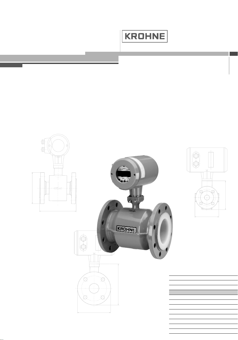
ALTOFLUX 2W
IFM 4042 K/EEx
2-wire compact
electromagnetic flowmeter
Variable area flowmeters
Vortex flowmeters
Flow controllers
Electromagnetic flowmeters
Ultrasonic flowmeters
Mass flowmeters
Level measuring instruments
Communications technology
Engineering systems & solutions
Switches, counters, displays and recorders
Heat metering
Pressure and temperature
Page 2

Warning!
• No safety technical changes may be made to the devices. Unauthorized changes might affect
the explosion safety of the devices.
• These additional instructions are an extension to the Installation and Operating Instructions
and only applies for the EEx version of the IFM 4042 K magnetic-inductive compact
flowmeter. All technical information described in the Installation and Operating Instructions
are applicable, when not specifically excluded or replaced by the instructions in these
additional instructions.
Contents
1 System components 3
1.1 General information 3
1.2 Data plates 4
1.3 Primary head 4
1.4 IFC 040-EEx signal converter 5
1.4.1 Electronics compartment 5
1.4.2 Terminal compartment 5
1.5 Cable or conduit entries 5
2 Electrical connection 6
2.1 Equipotential bonding system 6
2.2 Terminal arrangement 6
2.3 Description of the output circuits 6
2.4 Connection diagram 8
2.5 Safety-technical data 9
2.6 Connection examples 9
2.6.1 Example of IFM 4042 K in 2-wire mode 9
2.6.2 Example of IFM 4042 K in 2×2-wire mode (4-wire) 10
3 Operation of the signal converter 11
4 Maintenance 11
5 Ordering information 11
6 Technical data 11
7 Replacement of electronic unit 12
7.1 Removal of the electronics unit 12
7.2 Inseration of the electronics unit 12
8 EC Declaration of conformity 13
9 EC-Type examination certificate 14
Be sure to follow these instructions!
Important!
• The prescriptions and regulations as well as the electrical data described in the EC-type
examination certificate must be obeyed.
• Beside the instructions for electrical installations in non-hazardous locations according to the
applicable national standard (equivalent of IEC 364, e.g. VDE 0100), especially the
regulations in EN 60079-14 "Electrical installations in hazardous locations" or equivalent
national standard must be followed.
• Installation, establishment, utilization and maintenance are only allowed to be executed by
personnel with an education in explosion safety!
2 ALTOFLUX 2W IFM 4042 K - EEx
Page 3
1 System components
1.1 General information
General information The Altoflux 2W IFM 4042 K-EEx electromagnetic compact flowmeter in 2wire technology is in accordance with European Directive 94/9/EC (ATEX 100a) and approved
for hazardous classified locations of Zone 1 and 2 under:
KEMA 01 ATEX 2200 X
The IFM 4042 K-EEx compact flowmeter is designed for ambient temperatures in the range of
-40°C up to +60°C.
The allowed process liquid temperature is a.o. limited by the combustible atmosphere that
(possibly) surrounds the apparatus, which again is determined by the temperature class of the
atmosphere (first column of the tables). See tables below for details.
For dusts the second column of the two below listed tables is applicable.
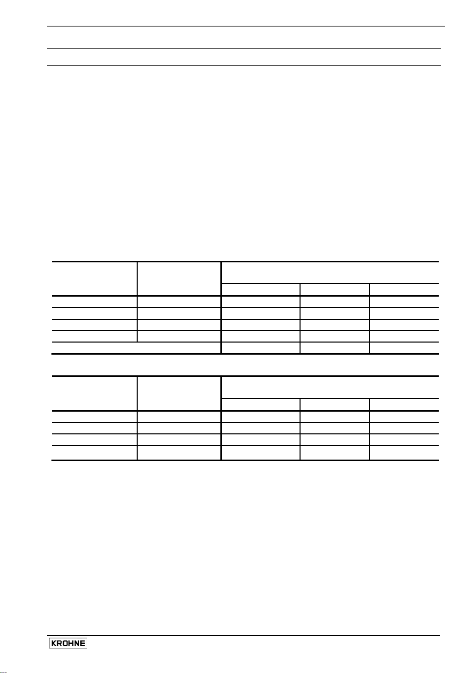
Temperature classification DN 25 - 150 with PFA liner
Temperature
class
(for gases) (for dusts)
T6 T85°C 70°C 70°C 70°C
T5 T100°C 85°C 85°C 85°C
T4 T135°C 120°C 120°C 115°C
T3 T180°C 180°C 180°C 115°C
Use heat-resistant cables no no yes
Temperature classification DN 10 - 20 and >DN 200
Temperature
class
(for gases) (for dusts)
T6 T85°C 75°C 70°C 70°C
T5 T100°C 95°C 90°C 75°C
T4 T135°C 130°C 115°C 75°C
T3
Max. surface
temperature
Max. surface
temperature
T180°C
*
Maximum process liquid temperature
≤ 40°C Ta ≤ 50°C Ta ≤ 60°C
T
a
Maximum process liquid temperature
≤ 40°C Ta ≤ 50°C Ta ≤ 60°C
T
a
150°C 115°C 75°C
* T 150 °C for DN 10-20 and > DN 200
The IFM 4042 K-EEx flowmeter consists of the IFC 040-EEx signal converter unit, which is
screwed on top of the primary head (i.e. the measuring unit). The compact flowmeter is marked
with one of the codes below, depending on the meter size:
• DN 10 - 20 II 2GD EEx dme [ib] IIC T6…T3 ("EEx e and d" terminal compartment)
• DN 25 - 150 II 2GD EEx de [ib] IIC T6…T3 ("EEx e and d" terminal compartment)
• DN 200 - 300 II 2GD EEx dqe [ib] IIC T6…T3 ("EEx e and d" terminal compartment)
• DN 350 and up II 2GD EEx de [ib] IIC T6…T3
("EEx e" and "EEx d" terminal compartment)
For details see the EC-type examination certificate in Section 9 of these instructions.
ALTOFLUX 2W IFM 4042 K - EEx 3
Page 4
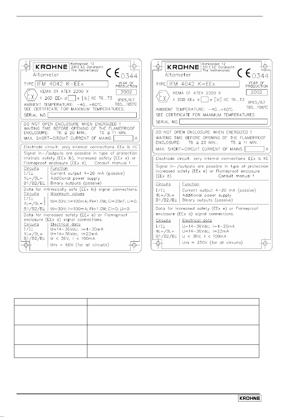
1.2 Data plates
IFM 4042 K-EEx, type "EEx de [ib]"
IFM 4042 K-EEx, type "EEx de"
1.3 Primary head
The primary head is the measuring unit of the IFM 4042 K-EEx compact flowmeter and contains
two field coils (see table below for the type of protection) and two electrodes in type of
protection intrinsic safety category "ib" according to EN 50020.
Meter size Type of protection
DN 10 up to DN 150 Housing: Encapsulation "m" according to EN 50028 and
increased safety “e” according to EN 50 019
Electrodes: Intrinsic safety "ib" according to EN 50020
DN 200 up to DN 300 Housing: Powder filling “q” according to EN 50017 and
increased safety “e” according to 50 019
Electrodes: Intrinsic safety "ib" according to EN 50020
DN 350 and larger Field coils: Increased safety "e" according to EN 50019
Electrodes: Intrinsic safety "ib" according to EN 50020
NOTE
4 ALTOFLUX 2W IFM 4042 K - EEx
The intrinsically safe electrode circuits of the IFM 4042 K-EEx compact flowmeter
are only internal circuits and not accessible for the customer.
Page 5

1.4 IFC 040-EEx signal converter
The IFC 040-EEx signal converter consists of a cylindrical housing of die-casted aluminum, which
has two separate compartments, divided from each other by an integrated wall with casted
flameproof terminal feed-through. The neck at the bottom of the housing contains a flameproof
cable feed-through. The signal converter housing is on both ends closed by a cylindrical threaded
cover with O-ring sealing. The housing has an ingress protection degree of at least IP67 conform
to EN 60529.
1.4.1 Electronics compartment
The electronics compartment accommodates the pre-certified IFC 040-EEx electronics unit with
approval number PTB 00 ATEX 2213 U. The compartment is designed with type of protection
flameproof enclosure "d" according to EN 50018. It is closed by a flameproof display cover with
glass window.
1.4.2 Terminal compartment
The terminal compartment has seven terminals for connection of the current output (I, I⊥), the
additional power supply or "Power Booster" (1L=, 0L=) and binary pulse/status outputs (B1, B⊥,
B2). Chapter 2 shows the terminal arrangement of the IFC 040-EEx. There are two versions
possible with a different explosion protection according to the European Standards, which is
dependent on the safety-technical maximum voltage Um of the mains power supply system to
which the flowmeter is connected.
Version A Terminal compartment "EEx de [ib]" with Um = 60 V
The connections of the output circuits can be configured by the customer in one of the following
types of explosion protection:
• EEx [ib] (intrinsic safety, category "ib") or
• EEx e (increased safety) or when the precaution in section 1.5 is obeyed
• EEx d (flameproof enclosure)
•
Version B Terminal compartment "EEx de" with Um = 250 V
The customer can configure the connections of the output circuits in one of the following types of
explosion protection:
• EEx e (increased safety) or when the precaution in section 1.5 is obeyed
• EEx d (flameproof enclosure)
The two versions (A and B) of the terminal compartment as well as their requirements are
described in more detail in section 2.3 of these additional instructions.
1.5 Cable or conduit entries
The used cable entries (glands and/or blind plugs) must be ATEX certified. Standard the IFM 4042
K-EEx flow-meter is delivered with an EEx e cable gland and EEx e blind stop. (see also the EEx
code on cable gland and blind stop). The cable gland and blindstop are suitable for connections in
EEx e and EEx ib, but not for EEx d.
Safty technical note
Therefore, when connection in EEx d is planned a special EEx d certified conduits, gland(s) or
blindstops must be used! ATEX approved "EEx d" cable glands, screw-threaded adapters as well
as blind plugs are no integral part of the delivery package and must be purchased by the customer
himself or can be ordered through their (local) Krohne representative as special parts ! Note that
for a correct choice of the EEx d cable gland the precise cable type and cable dimensions (e.g.
outside diameter) must be given.
ALTOFLUX 2W IFM 4042 K - EEx 5
Page 6
2 Electrical connection
2.1 Equipotential bonding system
The IFM 4042 K-EEx magnetic-inductive compact flowmeter must be incorporated into the
equipotential bonding system through the internal of external PE-clamp. Latter clamp is suitable
for wires till 4 mm2 cross section.
Disconnection from the equipotential bonding system is only allowed when the flowmeter is not in
contact with power supplies or ground voltages outside the hazardous area.
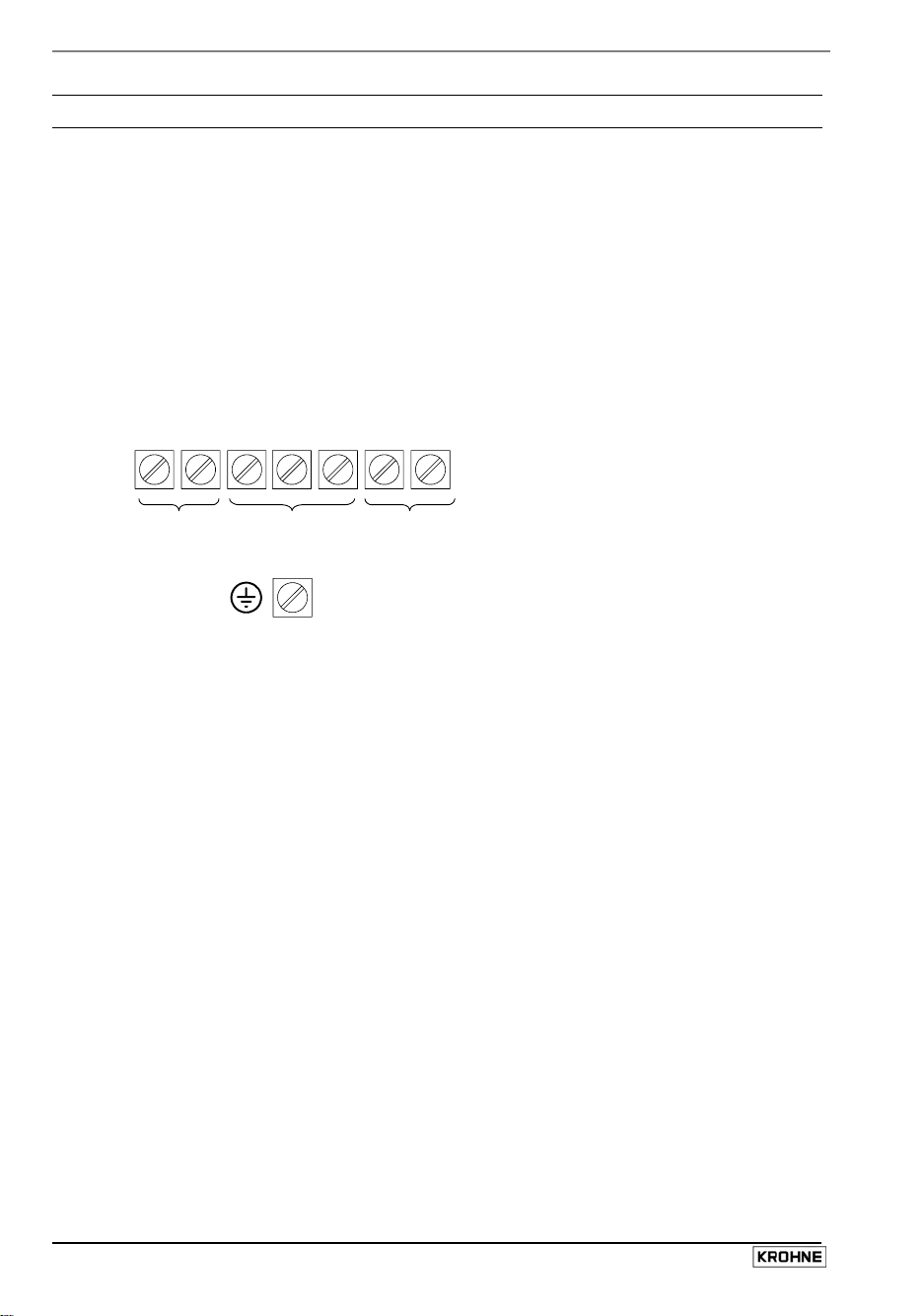
2.2 Terminal arrangement
To connect external devices to the signal output terminals, the wiring requirements for the type of
protection of the compartment must also be conform to the international or national standard
involved (e.g. EN 60079-14). The terminal arrangement is shown by the following figure.
Terminal arrangement in terminal compartment
I⊥ I B1 B⊥ B2 1L= 0L=
current binary power booster
output outputs (additional power supply)
PE protective ground
FE functional ground
The following outputs are available for connection to external circuits (see figure above):
Current output (terminals I, I ⊥)
This circuit constitutes a passive 4-20 mA current loop and includes the HART protocol of the
communication device (choice of polarity is free).
Additional power supply or Power Booster (terminals 1L=, 0L=)
These terminals are connected to provide the 2x2 wire mode (choice of polarity is free).
Binary outputs (terminals B1, B⊥, B2)
Terminals B1 and B⊥ can be configured as pulse or status output through software.
Terminals B2 and B⊥ can be configured as pulse or status output to NAMUR.
Galvanical separation of circuits
The internal electrode circuit with type of protection "EEx ib" is galvanically connected to the
aluminum signal converter housing (i.e. PE potential).
The current output, the additional power supply and the internal field current circuit are
galvanically connected to each other.
2.3 Description of the output circuits
The terminal compartment of the IFM 4042 K-EE is, with respect to the explosion protection,
available in two versions. The version can be identified by the information that is listed on the
data plate, which is mounted on the signal converter housing.
6 ALTOFLUX 2W IFM 4042 K - EEx
Page 7
Version A Terminal compartment "EEx de [ib]" with Um = 60 V
The customer can decide in which type of explosion protection the output circuits - current output,
additional power supply and binary outputs (i.e. pulse and/or status outputs) - can be driven: in
type of protection "EEx ib", "EEx e" or "EEx d".
If type of protection EEx e or EEx d is used, the markings for "Intrinsically safe" - that are blue oring around the cable gland and the blue sticker in the connection compartment - should be
removed.
The safety-technical maximum voltage Um (maximum effective AC or DC voltage) of the mains
power supply system for the terminal compartment in type of protection EEx de [ib] is restricted to
60 V. With this maximum voltage it is guaranteed that the protective components on which the
intrinsic safety of these circuits depends are not overloaded. This condition is met if the mains
power supply system satisfies the PELV requirements in accordance with IEC 364 / IEC 536.
Safety technical note
• It is not allowed to mix two different types of protection (e.g. current output in type of
protection "EEx ib" and pulse/status outputs in "EEx e" or "EEx d").
• The end-user is allowed to change the type of protection of the terminal compartment by the
afterwards a random times, when it is garuanteed that the maximum voltage U
of the mains
m
power supply system is always limited at 60 V!
Version B Terminal compartment "EEx de" with Um = 250 V
This version is intended for applications were the mains power supply system provides a
maximum safety-technical voltage of Um = 250 V. The terminals can either be provided with type
of protection increased safety "EEx e" according to EN 50019 or flameproof enclosure "EEx d"
conform to EN 50018. Type of protection intrinsical safety "EEx ib" is not allowed for this version.
Important notes (applicable for versions A and B)
• The intrinsically safe "EEx ib" internal electrode circuit is supplied by the IFC 040-EEx signal
converter electronics unit inside the electronics compartment. This circuit is separated from all
other circuits up to a maximum voltage of Um = 250 V according to En 50020. The internal
electrode circuit with type of protection intrinsic safety "ib" is galvanically connected with the
PE (housing potential).
• The current output (terminals I, I⊥) and the additional power supply (terminals 1L=, 0L=) must
be galvanically separated connected and driven from each other. To avoid voltage or current
summation, at least one of the two circuits must be isolated from earth potential. It is not
allowed to drive both circuits at the same time with grounded zener barriers. Both current
circuits, including all connection cables, must be galvanically separated at all times according
to the valid regulations.
• Also in case of non-intrinsically safe connections, it is absolutely necessary to maintain a
galvanic separation between the current output circuits and the additional power supply
connections.
• A safe connection of the IFC 040-EEx signal converter electronics with the equipotential
bonding system is achieved through the zinc-plated mounting frame, which must be securely
screwed to the aluminum signal converter housing (PE potential) by means of two longshafted screws. To access the two long-shafted screws it is necessary to unscrew the display
unit and fold it aside. The screws must be tightly secured with a torque of 1.3 Nm (a 2 Pt.
Phillips screwdriver is recommended).
ALTOFLUX 2W IFM 4042 K - EEx 7
Page 8

A
2.4 Connection diagram
signal outputs 1L= 0L= PE
(optional)
2
IFC 040-EEx
signal converter
I ⊥ I B1 B⊥ B2 1L= 0L=
current binary power
output outputs booster
terminal compartment
electronic compartment (always "EEx d")
electrode circuits field coil circuits
B (optional)
PE
FE
flameproof (EEx d)
terminal feed-through
Hazardous locations
of Zone 1 and 2
coil
flow tube
E
equipotential bonding conductor ≥ 4 mm
E
coil
IFS 4002…-EEx
primary head
8 ALTOFLUX 2W IFM 4042 K - EEx
Page 9

r
V
/
2.5 Safety-technical data
Important The functional-technical data must also be regarded,
therefore see the standard installation and operating instructions.
Safety-technical data of output circuits
Terminal Function Electrical data (per circuit)
designation
Circuit 1
I, I ⊥
Circuit 2
1L=, 0L=
Type of protection "EEx ib" Type of protection "EEx e"
Current output, passive
(2-wire connection)
4 - 20 mA, HART =
possible
Additional power supply
or Power Booster,
(4-wire connection)
Maximum values:
Ui = 30 V, Ii = 100 mA,
P
= 1.0 W
i
= 20 nF, Li = 0
Ci
= 60 V
U
m
= 14 - 36 Vdc
U
n
= 4 - 20 mA
I
n
U
= 250 V
m
Un = 14 - 36 Vdc
I
= 22 mA
n
= 250 V
U
m
additional to circuit 1
(option)
Circuit 3
B1, B⊥
B2, B⊥
Passive pulse/status
output 1
Passive pulse/status
output 2
Maximum values:
= 30 V, Ii = 100 mA,
U
i
P
= 1.0 W
i
= 0, Li = 0
C
i
U
= 60 V
m
Maximum values:
U = 36 V
I = 100 mA
= 250 V
U
m
2.6 Connection examples
In the following sections examples for connection of the IFM 4042 K-EEx compact flowmeter are
described for operation in the 2-wire mode as well as in the 2x2-wire mode.
2.6.1 Example of IFM 4042 K in 2-wire mode
The diagram shows an IFM 4042 K-EEx with the terminal compartment in version A (EEx de [ib]
with Um = 60 V). The flowmeter is connected through a transmitter power supply ("EEx i"
approved) in 2-wire mode. If data communication with the flowmeter through the HART protocol is
required, the transmitter power supply unit must be HART compatible. Terminals I, I⊥ are not
polarity sensitive.
The entity parameters of the "EEx i" approved transmitter power supply, including the cable
capacitances and inductances, must fit the entity parameters of the IFM 4042 K-EEx-EEx compact
flowmeter, namely Ui = 30 V, Ii = 100 mA, Ci = 200 nF, Li = 0. Suitable HART compatible transmitter power supplies that can be used in combination of the Altoflux 2W IFM 4042 K-EEx are:
• Phoenix PI/Ex-ME-RPSS-I/I
• CEAG 6/420
Hazardous Area
Safe Area
IFM 4042 K-EEx
I
4-20 mA
Transmitter Powe
Supply (EEx i)
4-20 mA
Process
Display Unit
I ⊥
s
HTT
ALTOFLUX 2W IFM 4042 K - EEx 9
Page 10

A
V
2.6.2 Example of IFM 4042 K in 2×2-wire mode (4-wire)
The diagram shows an example of the connection of the IFM 4042 K-EEx in 2x2-wire mode. As in
the previous example (see Sect. 2.6.1), the terminal compartment is again version A.
The additional power supply (terminals 1L=, 0L=) of the IFM 4042 K-EEx is supplied by an
external power supply unit through an "EEx i" zener barrier with a linear output load. The
connection of the current output (terminals I, I ⊥) and the additional power supply
(terminals 1L=, 0L=) is insensitive for polarity reversal.
Important notes!
Only one of the two connected circuits of the IFM 4042 K-EEx, namely the "currrent output" or the
"additional power supply" may be earthed to maintain the required galvanic separation between
the two circuits!
It is strictly interdicted to use the IMoCOM adapter with the IFC040-EEx unit!
Hazardous Area
Safe Area
IFM 4042 K-EEx
I
4-20 mA
Transmitter Power
Supply (EEx i)
4-20 m
Process/
Display Unit
I ⊥
s
HTT
1L=
0L=
22 mA
Zener Barrier
+
_
External
Power Supp ly
The voltage of the external power supply unit must be carefully chosen to keep it within the
allowed limits. The upper limit is determined by the maximum working voltage of the zener barrier,
which in general lies a few volts below the maximum open voltage value Uo of the used zener
barrier. The lower limit is determined by the sum of the minimum working voltage of the additional
power supply of the IFM 4042 K-EEx flowmeter of 14 V and the voltage drop over the zenerbarrier
caused by the end-to-end resistance of the barrier and (if not neglectable) the serie cable
resistance. This voltage drop can be significant. The above described determination of the
external power supply voltage is explained by the following example.
Example with typical parameters:
Zener barrier data: U
I
= 28 V
0
= 93 mA
0
Maximum working voltage = 25.5 V
End-to-end resistance = 340 Ω
The voltage drop across the end-to-end resistance of the zener barrier is: 22 mA x 340 Ω = 7,5 V
This means that the external power supply must supply an output voltage to the zener barrier that
lies in the range somewhere between 21,5 - 25,5 V. The voltage over the terminals of the
additional power supply of the IFM 4042 K-EEx is in that case between the required 14,0 - 18,0 V.
10 ALTOFLUX 2W IFM 4042 K - EEx
Page 11

3 Operation of the signal converter
The IFM 4042 K-EEx contains the IFC 040-EEx signal converter electronics unit, which is
equipped with a display unit that contains magnetic Hall sensors. These Hall sensors enable the
settings of the IFC 040-EEx electronics unit to be set respectively reset with the help of the with
the apparatus delivered bar magnet without opening the flameproof signal converter housing in
the hazardous area.
Consult the standard Installation and Operating Instructions for the program functions of the
software of the IFC 040-EEx electronics unit.
4 Maintenance
The IFM 4042 K-EEx magnetic-inductive compact flowmeters are maintenance free with regard to
the flowmetering properties. Within the scope of the periodical inspections, which are required for
electrical apparatus that are installed and used in hazardous classified locations, it is
recommended to check the flameproof enclosures on signs of damage or corrosion. This
concerns the converter housing and for sizes DN25 till DN150 also the primary head housing.
5 Ordering information
In case of questions about spare or replacing parts contact your local Krohne representative. The
part number of the IFC 040-EEx electronics unit is 2.12896.01.00.
6 Technical data
Safty technical note
The following maximum safty technical process liquid temperatures are absolute safety-technical
limits. Due to function-technical reasons (e.g. measuring accuracy) lower process liquid
temperatures can be in effect, see also the standard installation and operating instructions of the
Altoflux 2W electromagnetic compact flowmeter type IFM 4042 K-EEx!
Ambient temperature Ta -40°C…+60°C
Maximum saftety technical process liquid temperature
see EC-Certificate of the IFM 4042 K-EEx with No. KEMA 01
ATEX 2200 X in Sect. 9 and the Tables in Sect. 1.1
ALTOFLUX 2W IFM 4042 K - EEx 11
Page 12

7 Replacement of electronic unit
Important!
The following instructions must be followed carefully, when the IFC 040-EEx signal converter
housing has to be opened respectively closed again !
Before opening
• Make absolutely sure that there is no explosion hazard!
• If necessary provide a "Gas-free certificate"!
• Make sure that all connecting cables are safely isolated from the power supply!
When the instructions above are strictly followed, the display cover (with the glass window) can be
removed.
7.1 Removal of the electronics unit
• Raise the latch of the interlocking device by loosening the hexagon socket head cap screw
size 3, until the cover can rotate freely.
• Unscrew the cover with the special plastic wrench (black) that is supplied with the apparatus.
• Unscrew the two screws of the display unit and turn it carefully aside.
• Carefully disconnect the 12 pin connector (for field coil and electrode circuits connection) from
the electronic unit.
• Unscrew the two mounting screws of the electronics unit, which fixes the metal frame to the
back of the signal converter housing. A crosshead screwdriver type 2 Pt. Phillips is most
suitable.
• Carefully remove the electronics unit of the converter housing (see the Remark below).
Remark!
Carefully keep the connecting cables of the field coil and electrode circuits to the side of the
housing, while removing respectively inserting the electronics unit into the signal converter
housing. This is to prevent damaging of the connecting cables!
7.2 Insertion of the electronics unit
Reassemble in reverse order with the replacement of the IFC 040-EEx electronics unit:
• Insert the electronics unit in the converter housing
• Tighten the two mounting screws of the electronics unit.
• The metal frame of the IFC 040-EEx electronics unit must be securely screwed to the housing
(back-end of electronics compartment) by the two non-removable fastening screws. Screw
them with a tightening torque of 1.3 Nm.
Remark!
These two screw-connections also establish the safety-technical connection of the electronics unit
to the signal converter housing and equipotential bonding system.
• Connect the 12-pin connector
• Mount the display-unit
• Before the cover is screwed back into the housing, the screw-thread must be clean and well-
greased with an acid and resin-free grease, e.g. silicone grease.
• Screw the display cover as tight as possible into the housing by hand, so that the gasket of the
cover must be clamped to provide the required Ingress Protection (IP) degree.
• Tighten the hexagon socket head cap screw of the interlocking device.
Refer to the standard Installation and Operating Instructions for detailed information about
resetting and reprogramming the new electronics unit after replacement.
12 ALTOFLUX 2W IFM 4042 K - EEx
Page 13

8 EC Declaration of conformity
ALTOFLUX 2W IFM 4042 K - EEx 13
Page 14

9 EC-Type examination certificate
14 ALTOFLUX 2W IFM 4042 K - EEx
Page 15

ALTOFLUX 2W IFM 4042 K - EEx 15
Page 16

16 ALTOFLUX 2W IFM 4042 K - EEx
Page 17

ALTOFLUX 2W IFM 4042 K - EEx 17
Page 18

18 ALTOFLUX 2W IFM 4042 K - EEx
Page 19

ALTOFLUX 2W IFM 4042 K - EEx 19
Page 20

20 ALTOFLUX 2W IFM 4042 K - EEx
Page 21

ALTOFLUX 2W IFM 4042 K - EEx 21
Page 22

 Loading...